Port of Ferrol enlargement works, Spain - Archivo Digital...
10
Port of Ferrol enlargement works, Spain Ignacio de la Pen ˜ a Zarzuelo Head of the Investment and Planning Director, Ferrol - San Cibrao Port Authority, Muelle Curuxerias s/n, Ferrol, A Corun ˜ a, Spain The Port of Ferrol is in the autonomous region of Galicia, in the north-west of the Iberian peninsula, in the ria of the same name. The port has traditionally specialised in bulk goods, mainly coal, scrap and petroleum products. An increase in traffic in the 1990s, combined with the diversification policy in the port authority activities, and the advisability to have a new container terminal, led the Port Authority to consider a major expansion project in the outer part of the ria. This paper provides an account of the works that were involved in this project (carried on from 2001 to 2005), known as the ‘Port of Ferrol enlargement works (outer harbour) – 1st stage’ and describes all the main construction processes (quarry, construction of breakwater, wharf, dredging processes, etc.) including the technological advances introduced at these works. 1. Description of the works The works took place in the so-called Ensenada de Canelin ˜as (Canelin ˜as Inlet; Figure 1), where they are sheltered from the biggest waves rolling in from the North Atlantic Ocean (NW) by way of Cabo Priorin ˜o Chico, which means that the design waves for designing the breakwater come from the west and are rather moderate (H s90 5 7?6 m for T 5 281 years). When selecting the ideal site, apart from the above-mentioned ‘shelter’ aspect, the following were considered: environmental questions, maritime and land access, the availability of natural depths, the quality of the quarry which would make it possible to supply the site with the materials required to perform the works, the fact that it had to be a safe distance from human settlements, compatibility with the urban development plans and the availability of low-cost land (see Grassa Garrido et al. (2009) for further details of the design studies). The drawbacks inherent to the site are that it has neither road nor rail access, and that the electricity, water supply and telecommunications services were inadequate, so it was necessary to undertake supplementary actions in this respect. The estimate for carrying out the infrastructure works at the first stage amounted to J135 million, plus a further J45 million for supplementary works, equipment and environmental restoration work. The deadline for carrying out the entire project was 44 months. By way of a summary, these works are listed here. (a) A 1040 m long rubblemound breakwater sloping at 57% (1 in 1?75), with a main armour layer consisting of 90 t concrete blocks overlying a mound composed of 25 t blocks and a secondary mound of 6 t natural riprap, all founded directly on the natural seabed without any prior dredging work being required. The breakwater head slopes at 50% (1 in 2) and is constructed with 90 t blocks, reaching depths of 32 m. The breakwater faces E 55˚ S. It has a concrete parapet whose crest lies at elevation 18 m. (b) A 172 m long arm leading off at right angles from the final section of the breakwater, made up of two concrete caissons anchored at elevation 215?00 m, 15?65 m wide, 20?00 m deep and 40?95 and 66?85 m long, respectively. (c) A 1515 m long coastal wharf that was built in stages: 857?80 m were constructed at the first stage, leading off from the breakwater. This wharf is composed of concrete caissons founded at elevation 222?00 m. The wharf is 15?65 m wide, 24?00 m deep and 40?95 m long (10 units) and 66?85 m long (six units) and serves as an enclosure for the levelled area, having an effective surface area of 90 ha. Before the caisson foundations were laid, around 10 000 and 52 000 m 3 , respectively, of rock and loose materials were dredged, down to elevation 222?00 m. Apart from the aforementioned works, the new harbour works involve the construction accesses by land and levelling the area around the harbour, as well as the electricity and water supply networks and so on. 2. Description of the construction processes, layouts and works facilities and installations 2.1 Quarry: excavation, transport and grading A distinction was made between two types of ground when carrying out the quarry excavations (Figure 2): surface layer Maritime Engineering Volume 164 Issue MA2 Port of Ferrol enlargement works, Spain de la Pen ˜ a Zarzuelo Proceedings of the Institution of Civil Engineers Maritime Engineering 164 June 2011 Issue MA2 Pages 49–58 doi: 10.1680/maen.2011.164.2.49 Paper 800013 Received 04/04/2008 Accepted 04/06/2010 Keywords: maritime engineering/ports, docks & harbours ice | proceedings ICE Publishing: All rights reserved 49
Transcript of Port of Ferrol enlargement works, Spain - Archivo Digital...

Port of Ferrol enlargementworks, SpainIgnacio de la Pena ZarzueloHead of the Investment and Planning Director, Ferrol - San Cibrao PortAuthority, Muelle Curuxerias s/n, Ferrol, A Coruna, Spain
The Port of Ferrol is in the autonomous region of Galicia, in the north-west of the Iberian peninsula, in the ria of the
same name. The port has traditionally specialised in bulk goods, mainly coal, scrap and petroleum products. An
increase in traffic in the 1990s, combined with the diversification policy in the port authority activities, and the
advisability to have a new container terminal, led the Port Authority to consider a major expansion project in the
outer part of the ria. This paper provides an account of the works that were involved in this project (carried on from
2001 to 2005), known as the ‘Port of Ferrol enlargement works (outer harbour) – 1st stage’ and describes all the main
construction processes (quarry, construction of breakwater, wharf, dredging processes, etc.) including the
technological advances introduced at these works.
1. Description of the works
The works took place in the so-called Ensenada de Canelinas
(Canelinas Inlet; Figure 1), where they are sheltered from the
biggest waves rolling in from the North Atlantic Ocean (NW) by
way of Cabo Priorino Chico, which means that the design waves
for designing the breakwater come from the west and are rather
moderate (Hs90 5 7?6 m for T 5 281 years).
When selecting the ideal site, apart from the above-mentioned
‘shelter’ aspect, the following were considered: environmental
questions, maritime and land access, the availability of natural
depths, the quality of the quarry which would make it possible
to supply the site with the materials required to perform the
works, the fact that it had to be a safe distance from human
settlements, compatibility with the urban development plans
and the availability of low-cost land (see Grassa Garrido et al.
(2009) for further details of the design studies).
The drawbacks inherent to the site are that it has neither road
nor rail access, and that the electricity, water supply and
telecommunications services were inadequate, so it was
necessary to undertake supplementary actions in this respect.
The estimate for carrying out the infrastructure works at the first
stage amounted to J135 million, plus a further J45 million for
supplementary works, equipment and environmental restoration
work. The deadline for carrying out the entire project was 44 months.
By way of a summary, these works are listed here.
(a) A 1040 m long rubblemound breakwater sloping at 57%
(1 in 1?75), with a main armour layer consisting of 90 t
concrete blocks overlying a mound composed of 25 t
blocks and a secondary mound of 6 t natural riprap, all
founded directly on the natural seabed without any prior
dredging work being required. The breakwater head
slopes at 50% (1 in 2) and is constructed with 90 t blocks,
reaching depths of 32 m. The breakwater faces E 55˚ S. It
has a concrete parapet whose crest lies at elevation 18 m.
(b) A 172 m long arm leading off at right angles from the
final section of the breakwater, made up of two concrete
caissons anchored at elevation 215?00 m, 15?65 m wide,
20?00 m deep and 40?95 and 66?85 m long, respectively.
(c) A 1515 m long coastal wharf that was built in stages:
857?80 m were constructed at the first stage, leading off
from the breakwater. This wharf is composed of concrete
caissons founded at elevation 222?00 m. The wharf is
15?65 m wide, 24?00 m deep and 40?95 m long (10 units)
and 66?85 m long (six units) and serves as an enclosure for
the levelled area, having an effective surface area of 90 ha.
Before the caisson foundations were laid, around 10 000 and
52 000 m3, respectively, of rock and loose materials were
dredged, down to elevation 222?00 m.
Apart from the aforementioned works, the new harbour works
involve the construction accesses by land and levelling the area
around the harbour, as well as the electricity and water supply
networks and so on.
2. Description of the construction processes,layouts and works facilities andinstallations
2.1 Quarry: excavation, transport and grading
A distinction was made between two types of ground when
carrying out the quarry excavations (Figure 2): surface layer
Maritime EngineeringVolume 164 Issue MA2
Port of Ferrol enlargement works, Spainde la Pena Zarzuelo
Proceedings of the Institution of Civil Engineers
Maritime Engineering 164 June 2011 Issue MA2
Pages 49–58 doi: 10.1680/maen.2011.164.2.49
Paper 800013
Received 04/04/2008 Accepted 04/06/2010
Keywords: maritime engineering/ports, docks & harbours
ice | proceedings ICE Publishing: All rights reserved
49

and rock. The first of these included the layer of soil and the
rock that has been weathered to such an extent that it can be
excavated using mechanical resources. Explosives had to be
used to excavate the second type of ground (rock).
Once the blasting had been completed, the loading and transport
equipment (back diggers and dumpers up to 100 t; Figure 3)
entered the quarry site, and groups of equipment were formed
on the basis of the average cycles. However, they were generally
made up of one back digger and two dumpers. At certain points
in time, up to seven teams were working simultaneously.
The extracted material was classified in two stages. The first
part of the process consisted of a preliminary classification
being carried out by the loading resources in front of the
quarry face, namely the dumper drivers selected what quarry
stone was to be loaded (this being transported to intermediate
stockpiling facilities where the second stage was carried out,
the stone being classified into different sizes so that it could be
controlled and verified), generally into ungraded material or
general fill (which was deposited directly at the works site) or
material to be sent to the aggregate classification and crushing
plant.
2.2 Breakwater
2.2.1 Auxiliary quay
Before the construction work on the breakwater itself got
under way, it was necessary to prepare a levelled area where a
series of facilities could be fitted out that would make it
possible to: (a) load the barges that were going to discharge the
materials on the seabed, and (b) produce concrete to
manufacture blocks, as well as to store these and classify the
riprap for the construction of the breakwater.
A 150 m long auxiliary quay (Figure 4) was built for mooring
purposes that could accommodate depths up to 4 m at low
water springs level (LWSL), equipped with a loader that would
make it possible to load several barges at the same time,
regardless of the state of the tide. Two barges managed to
moor at this auxiliary quay, one with a capacity for 650 m3 and
the other with a capacity of 700 m3. A complete loading and
unloading cycle lasted from 45 to 60 min.
A temporary breakwater was built to provide sufficient shelter
on the auxiliary quay; it was provided with an armour layer of
natural stones weighing 6 t.
2.2.2 Laying the material from the sea
Each of the vessels was equipped with differential global
positioning system (DGPS) antennae to assist them in
5 km
N
Ferrol
Inner port
Spain
Ferrol
Outer port
Figure 1. Port of Ferrol – location
Figure 2. Equipment used for loading and transporting material Figure 3. Close-up of the quarry face
Maritime EngineeringVolume 164 Issue MA2
Port of Ferrol enlargementworks, Spainde la Pena Zarzuelo
50

depositing the ungraded material for the core and when
discharging the riprap (Figure 5). One of these antennae was
used to establish the exact discharge point, whereas the second
one established the alignment that indicated the direction that
the barge was facing. The laying grids were programmed every
day with the software concerned, and the entire process was
controlled by the works management.
These maritime laying processes enabled the breakwater to
progress as far as 28?00 m, as from that level the construction
process began to be carried out with land resources (dumpers,
bulldozers and cranes). It was thus possible to go ahead and
make progress on the breakwater all the year round, thereby
ensuring that the works performed would not be affected by
stormy spells, because at those depths no failures take place.
It was possible to load the barges (Figure 6) by pouring
directly out, where the ungraded material was concerned. In
the case of the riprap, however, this was done with the aid of a
back digger, so that the vessels would not be damaged.
2.2.3 Laying the material from dry land
Once elevation 28?00 m had been reached with the ungraded
material, the dumpers took over to complete the sections that had
been defined, as far as elevation 7?23 m, the final elevation for the
breakwater core, adopted using the criteria indicated below.
One of the critical processes for defining suitable production
cycles is to establish a progress elevation that is sufficient to
carry out the works under the local tide conditions (+4?65 m)
and the average wave actions in the zone. It is also extremely
important for safety reasons for the crest to be wide enough to
enable two off-road vehicles to be driven on it at the same time
and for them to be able to pass each other when one of them
has the block-laying crane mounted on it. For this reason, the
progress elevation was established at 7?23 m and the crest
width at 21?00 m.
Where the breakwater works were concerned, special impor-
tance was attached to the fact that it was not necessary to
construct winter heads, because all the progress on land in the
zone most exposed to wave action was made between April and
September in the third year, the parapet being completed in
December. This meant that the continuity of the construction
process had to be guaranteed by having sufficient stockpiles of
blocks and riprap when the initial section of the breakwater
was started, so that the entire construction process could be
completed in this period.
In spite of the above, a failure affected the breakwater at the
initial stages (March 2002) and approximately 100 m of the
Figure 4. Auxiliary quay and breakwater leading off it
Figure 5. Depositing the riprap on the seabed
Figure 6. Loading a barge with a back digger from the auxiliary
quay
Maritime EngineeringVolume 164 Issue MA2
Port of Ferrol enlargementworks, Spainde la Pena Zarzuelo
51

works were lost. However, the contracted company accepted
liability for this risk in view of the fact that the first sections of
the breakwater back onto the levelled areas of the harbour.
However, the loss of material and effects on the progress of the
works caused by the failure can be regarded as moderate and
the economic repercussions were only slight. As will be
analysed later, with reference to the dredging carried out to
construct the wharf, the failure had a negative effect on the
works, because pieces of riprap from the secondary armour
layer fell into the caissons in the rubble-mound zone, and these
had to be removed with the aid of a dipper.
Once the breakwater core had been completed with ungraded
material, the different layers of riprap for the different filter
layers were ready, and the same procedure was used as for the
ungraded material (putting it in place with a barge as far as
elevation 28?00 m and using a dumper from that point on); the
last part of the section defined in the project was given a finish
and profiled with the aid of a crane equipped with a tray.
2.2.4 Laying the blocks
The 90 t blocks were laid in place with a mobile caterpillar
crane (Figure 7) with a maximum load capacity of 650 t and
maximum jib range of 112 m, which was capable of laying 100
blocks per day, working round the clock. During the daytime,
the crane was used to lay the blocks and at night it was used to
lay the riprap with a tray.
Before each block was laid in place, its exact position had to be
defined using the geographical positioning system (GPS), care
being taken to ensure that the number of blocks laid per
section complied with the porosity requirements and the
number of layers established in the project. The control
software installed in the operator’s cabin was used for this
purpose, and this made it possible to issue daily lists of the
number of blocks laid and their exact positions; these activities
were then checked by the works management.
Apart from the capacity and range factors, the type of crane
was chosen on the basis of the versatility of its drive system.
Mobile caterpillar cranes were used because such vehicles can
be swiftly moved and withdrawn from their positions in the
event of a sudden storm warning, which is not the case with
other systems (cranes equipped with a ringer or superlift).
Another important factor that contributed to the progress
made in constructing the breakwater was planning the
production; this was done in such a way as to cause the least
possible delay between layers once the progress elevation on
land had been reached. The reason for this was to make it
possible to react sufficiently well in advance, in the event of a
warning being given about the imminence of a storm, so that
the works that had been constructed up until that point could
be protected from damage.
2.2.5 Manufacturing aggregates and concrete
One of the main characteristics of the works was that all the
material required was manufactured at the in situ facilities, so
it was essential to have aggregate grading and crushing plants
on the site as well as concrete manufacturing facilities.
It must also be pointed out that for certain massed concretes
(parapet and breakwater blocks) maximum aggregate sizes
were used with dimensions that are larger than usual (up to
80 mm). As will be analysed later, the sizes involved meant that
the quality control processes for the concrete were rather more
complex than usual, because the traditional test specimen
setting processes for standard dimensions could not be used.
(a)
(b)
Figure 7. Crane laying blocks
Maritime EngineeringVolume 164 Issue MA2
Port of Ferrol enlargementworks, Spainde la Pena Zarzuelo
52

A crushing plant with a production capacity of 300 t/h
(Figure 8) was constructed in situ to produce the aggregates
and subsequently manufacture the concrete. It produced six
stockpiles whose sizes were 40/80, 25/40, 12/25 and 6/12 mm,
plus two stockpiles of 0/6 mm (one washed and the other
unwashed), as well as one stockpile of tailings (that were used
for track and road maintenance works).
The final production at the plant was 1 200 000 t of aggregates.
As the source material was granodiorite, its characteristics were
such that for certain concretes (fundamentally those used for the
caissons), it was necessary to obtain sands with improved
qualities from beyond the works site and to give the concrete
greater initial strengths and to facilitate the sliding process.
A concrete production plant with a capacity for manufacturing
150 m3/h (Figure 9) was installed on the works site. It
consisted of two horizontal shaft forced mixers with a capacity
of 4500 l of dry concrete and two cement silos (100 t each) and
a further two with a capacity of 1000 m3. The plant was
designed with one loading ramp for each of the five hoppers
that each provided one of the aggregate sizes and the tanks
containing the additives used at each stage of the works.
2.2.6 Manufacturing blocks
Among the works construction procedure peculiarities were
the design for the block yard and the way that the concrete was
laid. It was produced directly from the centre and brought by
‘ROTEC’ conveyor belts, which obviated the need for concrete
mixer lorries to cross the works and allowed for an ongoing
concreting system with higher production.
This technology was successfully used to construct compacted-
concrete dams, but no references have been found concerning
their use in harbour structures. Therefore, if this is to be a
competitive option in terms of cost using the traditional
procedures, large quantities of concrete have to be laid in place
in a zone where there is very little room to manoeuvre, so the
lengths of the conveyor belts have to be shortened and there
have to be special points where there are swaying movements,
belt changes and so on, which are points where the weaknesses
inherent to the process are to be found, because the concrete is
exposed to the risk of segregation or desiccation.
The concreting facilities were split into the following activities.
(a) Hopper providing ongoing concrete supply. The hopper
receives the concrete manufactured at the plant, so that it
can be sent by perpetual screw/worm to a conveyor belt
that leads to a small hopper that, in turn, puts the
concrete on a conveyor belt again.
(b) Conveyor belt for transporting the concrete. The concret-
ing is done by way of a conveyor belt (Figure 10) that is
lying above a structure composed of 25 t blocks, which
are later used on the breakwater mound.
(c) Arm on caterpillar tracks for distributing concrete. A
caterpillar tractor that can turn a complete circle (360 )
and a telescopic distribution arm (Figure 11) that pours
out the concrete inside the formwork.
(d) Compacting the concrete. Once the concrete has been
poured it is vibrated, both manually (with needle
vibrators) and mechanically by means of a back digger
equipped with four long-range vibrators.
This system was used to pour the concrete directly into the
formwork with the aid of a crawler or distributor arm. A total
Figure 8. Aggregate manufacturing plant: at the end of the block
yard and the auxiliary quay
Figure 9. Concreting plant
Maritime EngineeringVolume 164 Issue MA2
Port of Ferrol enlargementworks, Spainde la Pena Zarzuelo
53

of five triple formworks were used in situ to manufacture 90 t
blocks and three quadruple formworks to manufacture the 25 t
blocks, in such a way that a total of fifteen 90 t blocks and
twelve 25 t blocks were concreted for each post.
A total of 7068 blocks weighing 90 t and 6429 blocks weighing
25 t were manufactured, three posts being completed every
day. The concreting process lasted between 4 and 6 h.
Once one post had been completed, namely after 6 h, and as
soon as the concrete had hardened sufficiently to be removed
from the mould, the formwork was removed and work
commenced on concreting a new post on the second of the
manufacturing lines, arranged running parallel to the previous
line. After 12 h had elapsed as from the start of the process,
work began on concreting a new post, the third one, and work
started on transporting the blocks that had been manufactured
at the first post to the storage yard, as long as they were now
strong enough to be raised by the grabbers in the gantry frame.
The blocks then remained there for a minimum of 14 days, if
the strengths so permitted, after which they were authorised to
be laid in place on the works.
The block storage yard (Figure 12) was 300 m 6 35 m and
covered an area of 10 500 m2; it had a capacity to store a total
of 678 blocks (90 t) on three levels and 432 blocks (25 t) on
four levels, approximately one month’s production working
with two posts per day.
The first quarter of the block storage yard (75 m) was the
manufacturing zone (the formwork was moved in parallel
fashion along four concreting lines, two on either side of the
ROTEC belts) and the remaining three-quarters was given over
to stockpiling the manufactured blocks.
Two gantry cranes (Figure 13) running on rails were used to
move the formwork and blocks. The first one had a capacity
for handling 35 t, and its only function was to move the
formwork between the four different manufacturing lines; it
only moved around in the first quarter of the yard. The second
one, with a handling capacity of 110 t, moved the blocks from
Figure 10. Close-up of the ROTEC conveyor belt
Figure 11. Close-up of the distributor arm or ‘crawler’ Figure 12. Block storage yard
Maritime EngineeringVolume 164 Issue MA2
Port of Ferrol enlargementworks, Spainde la Pena Zarzuelo
54

the manufacturing zone to the stockpiling zone and from the
stockpiling zone to the cradles that transported the blocks to
the zone close to where they were to be laid in place. Therefore,
the second crane moved around throughout the entire length of
the yard.
The formwork was designed to be slightly conical to facilitate
the process of removing the blocks from the mould, and the
grabbers were designed to have a system of hydraulic jacks in
the centre, which pushed the block inland, applying the
pressure necessary to separate the block from the formwork
without excessive friction.
As has already been pointed out, the statistical laws for the
concrete strength curves (age and strength) were obtained so
that the block storage yard would not have to be too large; this
meant that by obtaining test specimens that set after 1, 3 and
7 days, it could be guaranteed that a block whose strength after
7 days was greater than 22 MPa when an additive to speed up
the process was used, or was greater than 20 MPa if a
superflux were used, would reach the 30 MPa required in the
instructions after 28 days. In such cases authorisation was
given to lay the blocks after 14 days (when there was sufficient
traceability for the strength of each block).
Two cradles were used to transport the blocks from the yard to
the breakwater.
2.2.7 Constructing the superstructure
The parapet was constructed in five stages: foundation, slab,
body (two stages) and cantilever/wave-return wall. Metallic
formwork was used for the foundations and the slab. Sliding
formwork moved by gantries was used on the construction
process. The front of the gantries was supported on the lower
stage and the rear on the back part of the same stage once the
concrete was sufficiently hard (Figures 14 and 15).
Figure 13. Close-up of the gantries used to move the blocks in the
yard
Figure 14. Close-up of how the parapet construction work was
progressing
Maritime EngineeringVolume 164 Issue MA2
Port of Ferrol enlargementworks, Spainde la Pena Zarzuelo
55
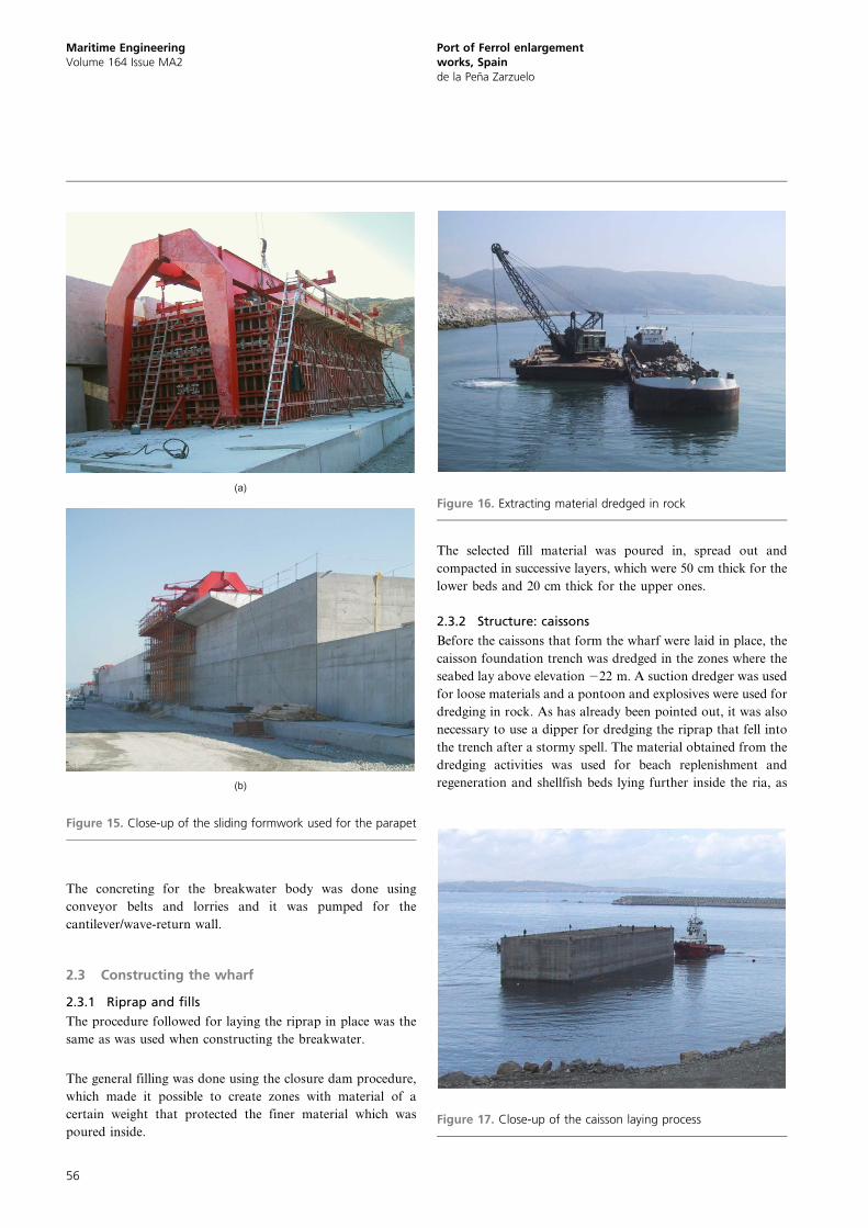
The concreting for the breakwater body was done using
conveyor belts and lorries and it was pumped for the
cantilever/wave-return wall.
2.3 Constructing the wharf
2.3.1 Riprap and fills
The procedure followed for laying the riprap in place was the
same as was used when constructing the breakwater.
The general filling was done using the closure dam procedure,
which made it possible to create zones with material of a
certain weight that protected the finer material which was
poured inside.
The selected fill material was poured in, spread out and
compacted in successive layers, which were 50 cm thick for the
lower beds and 20 cm thick for the upper ones.
2.3.2 Structure: caissons
Before the caissons that form the wharf were laid in place, the
caisson foundation trench was dredged in the zones where the
seabed lay above elevation 222 m. A suction dredger was used
for loose materials and a pontoon and explosives were used for
dredging in rock. As has already been pointed out, it was also
necessary to use a dipper for dredging the riprap that fell into
the trench after a stormy spell. The material obtained from the
dredging activities was used for beach replenishment and
regeneration and shellfish beds lying further inside the ria, as
(a)
(b)
Figure 15. Close-up of the sliding formwork used for the parapet
Figure 16. Extracting material dredged in rock
Figure 17. Close-up of the caisson laying process
Maritime EngineeringVolume 164 Issue MA2
Port of Ferrol enlargementworks, Spainde la Pena Zarzuelo
56
well as for other uses in situ: filling cells and trenches
(Figure 16).
Once the trench had been completed, work started on laying
and levelling the material for the mound, a barge being used
for the former and a dredger being used for the latter. A diving
team was then employed to finish off the work with pontoon
teams on the surface. The mound elevation was 220?00 m.
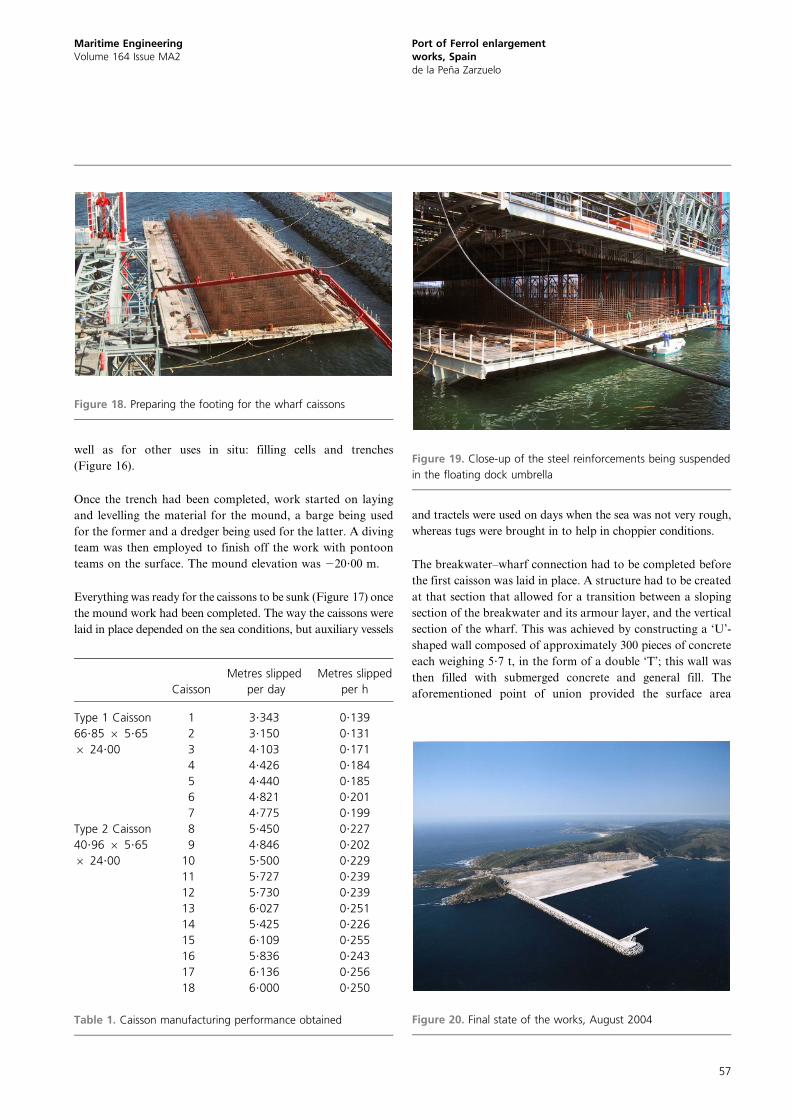
Everything was ready for the caissons to be sunk (Figure 17) once
the mound work had been completed. The way the caissons were
laid in place depended on the sea conditions, but auxiliary vessels
and tractels were used on days when the sea was not very rough,
whereas tugs were brought in to help in choppier conditions.
The breakwater–wharf connection had to be completed before
the first caisson was laid in place. A structure had to be created
at that section that allowed for a transition between a sloping
section of the breakwater and its armour layer, and the vertical
section of the wharf. This was achieved by constructing a ‘U’-
shaped wall composed of approximately 300 pieces of concrete
each weighing 5?7 t, in the form of a double ‘T’; this wall was
then filled with submerged concrete and general fill. The
aforementioned point of union provided the surface area
Figure 18. Preparing the footing for the wharf caissons
Caisson
Metres slipped
per day
Metres slipped
per h
Type 1 Caisson
66?85 6 5?65
6 24?00
1 3?343 0?139
2 3?150 0?131
3 4?103 0?171
4 4?426 0?184
5 4?440 0?185
6 4?821 0?201
7 4?775 0?199
Type 2 Caisson
40?96 6 5?65
6 24?00
8 5?450 0?227
9 4?846 0?202
10 5?500 0?229
11 5?727 0?239
12 5?730 0?239
13 6?027 0?251
14 5?425 0?226
15 6?109 0?255
16 5?836 0?243
17 6?136 0?256
18 6?000 0?250
Table 1. Caisson manufacturing performance obtained
Figure 19. Close-up of the steel reinforcements being suspended
in the floating dock umbrella
Figure 20. Final state of the works, August 2004
Maritime EngineeringVolume 164 Issue MA2
Port of Ferrol enlargementworks, Spainde la Pena Zarzuelo
57

required to moor the floating docks and to install the pumping
equipment needed to concrete the caissons.
A total of 18 caissons were prepared, 16 for the wharf and two
for the arm. Two floating docks were used in the process.
Caissons 66?85 m long, 17?65 m wide (including footing) and
24?00 m deep were made using the larger floating dock. The
caissons manufactured with the smaller one were the same
width and depth, but were only 40?96 m long. The caissons for
the arm were the same length (66?85 and 40?96 m) and width,
so that the same formwork could be used, but in this case they
were only 20?00 m deep.
The caisson construction and laying process took place in two
overlapping stages. First of all, the work began on the adjacent
pontoon (Figure 18), where all the steel for the caisson footing
was assembled and mounted, together with the most reinforced
part and the initial metres of the caisson walls. These tasks
took 2 days to complete. The concreting and reinforcing of the
wall for the other caisson was carried out simultaneously inside
the floating dock.
Once the footing had been reinforced, and with the floating
dock in its ballast position, the pontoon was inserted inside the
floating dock. The steel reinforcement structure for the footing
was then suspended from the caisson wall formwork, which
was supported by a series of gantry cranes that then made the
formwork slide along (Figure 19). The ballast was removed
from the floating dock once the metallic structure was
supported, and as soon as the top was lying above sea level
the metallic structure was supported on it. Immediately after
that, and while the footing formwork (60 cm high) was being
assembled, the metallic reinforcements for the first metres of
the caisson walls were inserted into the formwork and the
exterior of the caisson cells. When all the reinforcements were
in place the footing was concreted.
Once the footing was concreted, the formwork was lowered
down to the crest and work started on applying it to the
caisson wall (23?60 m). The formwork was slid at a rate
ranging from 0?20 to 0?25 m/h, approximately, so the floating
caisson was constructed in around 6 days. Table 1 shows the
performances obtained for each one of the caissons.
2.3.3 Constructing the superstructure
Sliding formwork was used for the section of each one of the
parts when concreting the edge beam, and the intermediate and
rear beams.
The concrete pavement was constructed after spreading and
compacting with a laser-controlled screed machine – lanes up
to 6 m wide being concreted, with transverse joints every 5 m.
2.4 Other facilities
A total of three weighing machines were installed at different
points in the harbour with a view to controlling and measuring
the riprap. Two of the weighing machines were 7 m 6 7 m
and had a capacity for 180 t, so that they could weigh the
dumpers, and one was a mixed weighing machine
(7 m 6 14 m) for weighing the dumpers and cradles that
weighed up to a capacity of 180 t.
Other auxiliary items and services were provided, such as
works transformers, electricity lines, a 2000 m3 water tank, so
that supplies could be guaranteed at the caisson construction
stage, complete quality control laboratories equipped with all
the items necessary and facilities needed to control the concrete
(wet chamber, press, etc.), car parks and yards for repairing the
machinery, works huts with changing rooms, first aid facilities
and a canteen (Figure 20).
REFERENCE
Grassa Garrido JM, Gutierrez-Serret R, Martın Soldevilla MJ, Ruiz
Mateo A and Santas Lopez JC (2009) Ferrol outer port:
experimental and in situ design studies. Proceedings of the
Institution of Civil Engineers – Maritime Engineering 162(2):
57–72.
WHAT DO YOU THINK?
To discuss this paper, please email up to 500 words to the
editor at [email protected]. Your contribution will be
forwarded to the author(s) for a reply and, if considered
appropriate by the editorial panel, will be published as
discussion in a future issue of the journal.
Proceedings journals rely entirely on contributions sent in
by civil engineering professionals, academics and stu-
dents. Papers should be 2000–5000 words long (briefing
papers should be 1000–2000 words long), with adequate
illustrations and references. You can submit your paper
online via www.icevirtuallibrary.com/content/journals,
where you will also find detailed author guidelines.
Maritime EngineeringVolume 164 Issue MA2
Port of Ferrol enlargementworks, Spainde la Pena Zarzuelo
58


![BiS chapter 31 (Ferrol onward) - The Bible in Spain · place and a bus station. 10 Since Borrow writes, in his letter from Oviedo of 29 September 1837 [Darlow, 251] that ‘a day](https://static.fdocuments.in/doc/165x107/60504e032c01bd6a67500447/bis-chapter-31-ferrol-onward-the-bible-in-spain-place-and-a-bus-station-10.jpg)