PONY 20 SCA -...
20
PONY 20 SCA IMPORTANT SAFETY INSTRUCTIONS READ AND UNDERSTAND ALL INSTRUCTIONS BEFORE OPERATING OR SERVICING MACHINE DANGER! Failure to Observe These Instructions Can Cause Personal Injury to Machine Operator, By-standers or Possible Machine Damage. SAVE THESE INSTRUCTIONS • When using an electrical appliance, basic precautions should always be followed, including the following: • NEVER attempt to service or perform maintenance functions while the machine is plugged into an electrical outlet. • NEVER attempt to operate this machine unless you have been trained in its operation. • NEVER allow an untrained person to operate this machine. • Use this machine ONLY as described in this manual. • NEVER operate this machine with a damaged, broken, cut, abraded or taped cord or plug. • ALWAYS connect this machine to a properly grounded electrical outlet. See the following pages for grounding instructions and wiring diagram. • NEVER leave this machine unattended when plugged in. Unplug the machine from the electrical outlet when not in use and before attempting repairs or maintenance. • ALWAYS turn this machine OFF before unplugging from the electrical outlet. • NEVER operate this machine in the presence of flammable or combustible liquids, such as gasoline, fumes or dusts. • NEVER attempt to pick up flammable or combustible liquids, such as gasoline, fumes or dusts. • NEVER handle the machine, cord, or plug with wet hands. • NEVER drop or insert any object into any machine opening. • ALWAYS keep face, fingers, hair or any body part, or loose clothing away from any machine opening or moving part. • NEVER pick up anything that is burning or smoking, such as cigarettes, matches or hot ashes. • ALWAYS use extreme care when cleaning on stairs or when this machine is placed on stairs. • NEVER operate this machine if it is not working properly, if it has been dropped, damaged, exposed to weather or dropped into water. Return the machine to a service center for examination and repair. • NEVER operate this machine with any air opening blocked. Keep all air openings free of dust, lint, hair, and the like. • NEVER operate this machine without a dust bag and / or filters in place. • DO NOT pull or carry this machine by it’s electrical supply cord, use the cord as a handle, close a door on the cord, pull the cord around sharp edges or corners, expose to heated surfaces, or set heavy or sharp objects on the cord. • NEVER disconnect the plug by pulling on the cord. To disconnect the cord from the outlet, grasp the plug, not the cord. • DO NOT allow this machine to be used as a toy. Close attention is necessary when used by or near children. • DO NOT expose to rain, snow or extremes in temperature. • DO NOT use this machine to vacuum a floor or upholstery.
Transcript of PONY 20 SCA -...

PONY 20 SCAIMPORTANT SAFETY INSTRUCTIONS
READ AND UNDERSTAND ALL INSTRUCTIONSBEFORE OPERATING OR SERVICING MACHINE
DANGER! Failure to Observe These Instructions Can Cause Personal Injuryto Machine Operator, By-standers or Possible Machine Damage.
SAVE THESE INSTRUCTIONS
• When using an electrical appliance, basic precautions should always be followed, including thefollowing:
• NEVER attempt to service or perform maintenance functions while the machine is plugged into anelectrical outlet.
• NEVER attempt to operate this machine unless you have been trained in its operation.• NEVER allow an untrained person to operate this machine.• Use this machine ONLY as described in this manual.• NEVER operate this machine with a damaged, broken, cut, abraded or taped cord or plug.• ALWAYS connect this machine to a properly grounded electrical outlet. See the following pages for
grounding instructions and wiring diagram.• NEVER leave this machine unattended when plugged in. Unplug the machine from the electrical
outlet when not in use and before attempting repairs or maintenance.• ALWAYS turn this machine OFF before unplugging from the electrical outlet.• NEVER operate this machine in the presence of flammable or combustible liquids, such as
gasoline, fumes or dusts.• NEVER attempt to pick up flammable or combustible liquids, such as gasoline, fumes or dusts.• NEVER handle the machine, cord, or plug with wet hands.• NEVER drop or insert any object into any machine opening.• ALWAYS keep face, fingers, hair or any body part, or loose clothing away from any machine
opening or moving part.• NEVER pick up anything that is burning or smoking, such as cigarettes, matches or hot ashes.• ALWAYS use extreme care when cleaning on stairs or when this machine is placed on stairs.• NEVER operate this machine if it is not working properly, if it has been dropped, damaged, exposed
to weather or dropped into water. Return the machine to a service center for examination and repair.• NEVER operate this machine with any air opening blocked. Keep all air openings free of dust, lint,
hair, and the like.• NEVER operate this machine without a dust bag and / or filters in place.• DO NOT pull or carry this machine by it’s electrical supply cord, use the cord as a handle, close a
door on the cord, pull the cord around sharp edges or corners, expose to heated surfaces, or setheavy or sharp objects on the cord.
• NEVER disconnect the plug by pulling on the cord. To disconnect the cord from the outlet, grasp theplug, not the cord.
• DO NOT allow this machine to be used as a toy. Close attention is necessary when used by or nearchildren.
• DO NOT expose to rain, snow or extremes in temperature.• DO NOT use this machine to vacuum a floor or upholstery.

GROUNDING INSTRUCTIONS
This machine must be grounded. If it should malfunction or break down, grounding provides a path ofleast resistance for the electric current in order to reduce the risk of electric shock. This machine isequipped with a cord having an equipment-grounding conductor and grounding plug. The plug mustbe plugged into an appropriate outlet that is properly installed and grounded in accordance with alllocal codes and ordinances. FAILURE TO DO SO MAY CAUSE ELECTROCUTION due toimproper connection of ground.
DANGERImproper connection of the equipment grounding conductor can result in a risk of electric shock.Check with a qualified electrician or service person if you are in doubt as to whether the outlet isproperly grounded. Do not modify the plug provided with the machine if it will not fit the outlet. Have aproper outlet installed by a qualified electrician.
This machine is for use on a nominal 120 volt circuit and has a grounding plug that looks like theplug illustrated in Figure A.
A temporary adapter that looks like the adapter illustrated in Figure B. may be used to connect this plugto a 2-pole receptacle as shown below if a properly grounded outlet is not available.
The temporary adapter should be used only until a properly grounded outlet (Figure A.) can beinstalled by a qualified electrician. The green colored rigid ear, lug, grounding clip or the like extendingfrom the adapter must be connected to a permanent ground such as a properly grounded outlet boxcover. Whenever the adapter is used, it must be held in place by a METAL screw.
Check the nameplate on the machine to be sure the voltage and cycle stated on the nameplate are thesame as the voltage and cycle of the electrical outlet that you’re using. DO NOT attempt to plug a115 volt machine into a 230 volt outlet.
Figure C. A machine that uses 230 volts may or may not have the grounding (earthed) plug attached tothe cord. For use within the U.S.A. - 230 volts, 60 HZ , the plug is already supplied the with cord. Foruse outside the U.S.A., it may be up to the purchaser to have a proper grounding (earthed) plug at-tached.
Always use a properly grounded 3-wire extension cord which has male and female plugs. Use only12-3 SJTWA type extension cords to a maximum length of 50 feet.

WIRING DIAGRAM
BASIC SAFETY PRECAUTIONSIt is always advisable to receive instructions from a person previously trained, however, if you arefamiliar with carpet cleaning, you should be able to operate this machine.• Always be sure to read and fully understand all of these instructions before attempting to operate
this machine.• Never allow anyone to operate this machine who has not been properly trained.• Refer to the complete safety and electrical warnings page.
MACHINE INSPECTION• Carefully unpack this machine and recycle all packing materials.• Inspect machine for damage or missing components. If damage is found, contact the freight company
to file a freight claim.
NOTEAlways wear tennis shoes. Street shoes or rubber cushioned shoes, when wet, will release absorbeddirt or grease onto the carpeting and cause resoiling. Wet shoes can cause the operator to slip and fallwhen walking from wet carpet onto bare floors. Make sure the soles of your shoes are wiped dry beforewalking onto a bare floor. Care should be taken as carpet cleaning solutions may attack abare floor.
CAUTION• NEVER stick your hands, feet, or any other objects under the brush head when the motor is
operating. Injury may result!
SPECIFICATIONSGeneral Machine Description• This machine is a self propelled carpet extraction machine, and is available in both 115 volt and 240
volt configurations.
OPERATOR CONTROLSOperator controls are positioned for ease of use, and include icons for simplified user training.• Attach the twist lock end of the power cord to the stub cord of the machine, plug the other end into an
appropriate electrical outlet. Move the speed control lever on the control panel to its slow speed. Turn“ON” the master switch. Check to see if the top clear dome is secure on the recovery tank then turnthe vac switch “ON” to make sure the vac motor is operating.
• To check on the brush and the pump for proper operation, turn both switches to “ON”. Squeeze thedeadman lever under the control handle, the brush should run. With the solution tank empty, thesolenoid that controls the pump should emit a short “bup-bup” sound.
OPERATION• Turn “ON” the master switch before turning “ON” the vacuum switch.• Turn “ON” the brush switch.• Turn “ON” the pump switch.• Lower the brush head assembly to the carpet with the left lift lever.• Lower the vacuum shoe to the carpet with the right lift lever.
Note: You may also “lockdown” the vacuum shoe to the carpet.• You must lift the vacuum shoe when moving this machine in reverse.• Squeeze the deadman lever under the control handle in order to propel forward, then turn on the
brush and spray. The brush and spray will stop when the deadman lever is released.• At the cleaning site turn the speed control to propel the machine at the required speed.• You can drive the machine to the cleaning site by squeezing the deadman lever with the pump and
vacuum switches “OFF”, and then turning the speed control to get the desired speed.
OPERATION AND INSTRUCTIONS

CONTROL PANEL• The master switch, in the upper left corner, must be turned on before any other switch can be activated.• The speed control is located just below the master switch, this knob controls the speed of the forward movement
of the machine.• On the right are three switches, from top to bottom they activate the spray, brush rotation, and suction.• Below these switches are two circuit breakers, the left is for the brush motor, the right is for the drive motor.
SOLUTION• The solution tank is the lower part of the machine body, with a capacity of 20 gallons. The tank is filled by
pouring the water and cleaning chemicals through the cloth filter at the front of the tank, and dispensing throughan in-line mesh filter screen at the solution tank outlet. The amount of fluid in the tank is visible via the clearhose at the back left of the machine. The tank may be drained by this hose by pulling down from the top. Thesolution pump is a 100 PSI continuous type, three piston bypass valve style.
RECOVERY TANK• The recovery tank is the upper part of the machined body and has a capacity of 20 gallons. There is a metal
screen cartridge on top of the vacuum tube under the clear dome. Turn the clear dome sideways to allow anopening in order to allow for the recovery tank and metal screen to air dry.
VACUUM MOTOR• The vacuum motor is a three stage, 1 3/4 HP bypass style, with peripheral discharge. It is enclosed in a housing
to reduce noise and improve cooling airflow.
GEAR DRIVE MOTOR• This machine is propelled by a gear reduction motor through a chain and sprocket system. Variable speed is
adjusted at the operator control panel.
BRUSH MOTOR / BRUSH ASSEMBLY• The brush is driven by a 1/4 HP permanent magnet motor, via a cog belt and pulley system. The brush is a 22”
wide nylon bristle, four-row chevron design. The brush housing assembly is a floating style.
SOLUTION SPRAY SYSTEM• Solution is applied to the carpet through a spray bar assembly of five evenly spaced spray tips. The spray bar is
easily serviced with the quick connect solution hose and quarter-turn removable spray tips. Positive shutoff ofsolution flow is controlled by an in-line solenoid.
ACCESSORY SPRAY WAND• This is a standard feature that may be used to prespray a wide area of carpet before extraction. It may also be
used to apply additional cleaning solution to trouble spots while extracting.
VACUUM SHOE• The vacuum shoe is a 27” wide, weighted aluminum casting. Mounted with a bearing and a nylon bushing it is
able to swing and swivel on a center arm. It is removable for cleaning or machine transportation by a quickdisconnect mechanism. The intake of the vacuum shoe must be kept clean to ensure proper flow of extractedliquids. The rear cover plate may be removed to allow for a detailed interior cleaning.
BODY / CHASSIS• This machine has a one year warranted rotocast poly body, mounted on a steel frame, which rides on two 8”
diameter wheels, with grooved non-marking rubber treads and two 4” diameter swivel casters.
ACCESSORY SOLUTION OUTLET• The quick connect accessory solution outlet, located at the rear of the machine and to the left (to which the
accessory spray wand hose is connected), can be used to attach any of the accessory kits. Disconnect the quickconnect that is attached to the accessory spray wand hose, and insert the solution hose which is part of any ofthe accessory kits. Solution from the solution tank is supplied to this outlet when the solution pump is “ON”, butwill only dispense solution when the trigger of the upholstery, stair tool or jet wand is squeezed in the “ON”position.
FEATURES

REPAIR SERVICE• Repair service for this machine must be performed by an authorized service center. Repair service performed by
unauthorized service companies will void the machine warranty coverage.• Turn off all switches and unplug this machine before beginning any service work.
OPERATOR CONTROL PANEL• All operator controls are serviced by removing the screws securing the switch control panel to the body. This
switch control panel will also allow access to the brush and vacuum shoe handle linkage. If the switches, circuitbreaker and variable speed control malfunction, they are not repairable, and must be replaced with new factoryparts. The power cord, switches and circuit breaker are checked for proper function by testing for continuity whenin the “ON” position.
SOLUTION TANK• To fill the solution tank make sure that the mesh filter is in place. Premix the extraction chemical (as per the
chemical manufacturer’s mixing instructions) with hot water (95°F/35°C max.) in a five gallon bucket and pour itinto the tank. High-foaming liquids waste the capacity of the recovery tank, always use a low-foaming extractionchemical.
• The mesh filter used to strain the solution poured into the solution tank should be removed after each use andrinsed in clear water before replacing.
• Clean solution must pass through an in-line mesh filter prior to entering the solution pump. This filter is mountedexternally under the right / rear side of the solution tank (body). To remove the screen for cleaning you must firstdisconnect the hex nut of the solution hose, and then turn the lower half of the filter 1/8 of a turn counterclockwise.
• Remove the lower half of the filter, and mesh screen to clean.CAUTIONIf there is any clean solution in the tank it will drain out at this time. Reassemble and check for leaks.
RECOVERY• Always use a defoamer to keep foam out of the vacuum motor fans. To efficiently defoam the recovered solution
that will be vacuumed into the recovery tank, simply remove the vac hose from the vac shoe. Turn “ON” thevacuum switch; vacuum two cups of defoamer into the recovery tank. Do not put defoamer into the solution tank.
EMPTYING THE SOLUTION AND RECOVERY TANKS• Any remaining solution should be drained into a toilet, slop sink, janitor’s closet, or bucket. If there is a small
amount of solution left in the solution tank, it is possible to vacuum the solution into the recovery tank (providedthere is sufficient room to handle the excess solution). It is necessary to turn the master switch and vacuum switch“ON”, so that the vacuum motor is running.
• Remove the vac hose which is connected to the vac shoe. Pull the clear solution tank hose down, and insertit into the vac hose. The vac hose will vacuum the solution into the recovery tank. When the solution tank is emptyturn the switches off. Remove the recovery tank hose from the bracket, clamp the hose with your hand and lower oraim the hose in the direction that you want the solution to flow. Turn the stopper counterclockwise and remove it,unclamp your hand and allow the solution to drain.
AFTER USE AND BEFORE STORAGE• Both the solution and recovery tanks should be drained after each use. In addition, both tanks should be rinsed
with clear water. Weekly flush out or clean the solution tank with a one gallon solution of 25% vinegar and warmwater. Pour it into the solution tank, turn the machine “ON” and operate it to completely clean the tank, and thespray jets, (running for 30 seconds should be sufficient). This will remove any chemical residue. Failure to flushthe solution system will result in poor spray patterns and corroded jet spray tips.
VACUUM MOTOR• To service or replace the vacuum motor, you must remove the cooling air intake and the upper vacuum
housing.
SOLUTION PUMP / SOLENOID• The solution pump is mounted at the rear of the chassis, and is secured to a mounting plate by four screws.• Eventually, the pump bypass valves may become weak or brittle during normal use (normal wear and tear),
as a result of being attacked by chemicals used in the cleaning process. The result will be a drop in thepump output pressure.
SERVICE AND MAINTENANCE
• Pump pressure is restored by replacement of the bypass valve kit (part number 38-9-203-1) or by replacementof the pump (part no. 48-9-459-1, 115 volt, or 38-9-201-1, 240 volt).
• The electric solenoid provides a positive cutoff of solution flow to the spray jet bar assembly. The solenoid isactivated (“ON”) when the deadman lever is lifted during operation.
MOTORSThe drive motor, vacuum motor, solution pump and solenoid are located inside the body of this machine.To gain access to these components, you must complete the following procedures:• Disconnect the power cord from the wall.• Empty all liquids from the solution tank and recovery tanks.• Disconnect the solution hose from the in-line solution filter, at the right side of the body.• Remove the vacuum hose from the vacuum shoe. Disconnect the vacuum shoe lift cable from the cable
bracket.• Locate the mounting studs and nuts for the swivel casters. Remove only the rear / outer nuts. This will
disconnect the rear of the main body from the chassis.• Lift the rear of the machine body to tilt forward for access (the prop rod that holds up the machine, is under the
solution tank).
DRIVE MOTOR / DRIVE CHAIN ADJUSTMENT• The propulsion drive motor is mounted at the front of the chassis, and secured by four hex bolts. Access to this
motor, and to the drive chain for chain tension adjustment and lubrication is from underneath the machine (at thefront of the machine).
• The drive chain tension should be checked every 90 days and adjusted if necessary. To adjust the drive chaintension, you must first loosen the four hex bolts in the chassis slots under the propulsion motor. Slide the motorforward to decrease, or backward to increase the chain tension.
• The drive chain should be lubricated every 90 days with a penetrating moisture resistant lubricant, using a spraycan with attachable straw to apply. DO NOT lubricate the chain when the machine is on a carpeted surface.Wipe off any excess lubricant before operating the machine.
• The propulsion motor and gear box have no service parts, and must be replaced as a single unit.
BRUSH MOTOR / BRUSH ASSEMBLY / BELTThe brush motor, brush assembly and belt are serviced by removing both parts of the plastic two-piece brushhousing cover.
• The brush drive belt tension is adjusted by first loosening the brush motor mounting hex nuts. Slide themotor toward the brush to decrease the tension, and away from the brush to increase the tension. Whenthe motor is in the proper position, the drive belt should have 1/4” to 3/8” deflection midway between themotor and brush pulley.
• To replace the brush drive belt, you must remove the brush shaft mounting screw at the pulley end andloosen the screw at the opposite end. Install the new belt on the pulleys, replace and tighten the brushshaft mounting screws, and adjust the belt tension.
• Bristles will wear to the point where there is not enough agitation of the carpet. The nylon roller wheel canbe raised to lower the brush deeper into the carpet. Remove the roller axle that attaches the roller wheelfrom its holding bracket, and reinstall the axle into the upper holes in the bracket.WARNINGDo not use the upper roller axle position with a new or nearly new brush. This will force the brush to anexaggerated down position, overload the circuit breaker, and damage the brush drive motor.
• The brush motor is protected by a circuit breaker mounted on the control panel. The circuit breaker will open(pop-up) when the brush motor is overloaded. When the circuit breaker “overloads” the stem will pop up toexpose the white portion of the shaft. Unplug the machine. Prior to resetting the circuit breaker, you must inspectthe brush assembly for obstructions such as foreign objects, strings around the brush shaft or “frozen” bearings.
• Reset the circuit breaker by pushing down on the stem until it “clicks” into the “ON” position.
SERVICE AND MAINTENANCE

• Adjustment or replacement of the brush assembly requires removing both brush shaft mounting screws,allowing the brush assembly to be removed from the housing. When installing the brush assembly, do notover tighten the shaft screws. This will prevent binding of the brush assembly.
• Replacement of the brush drive motor (no service parts avail.) requires the removal of the mounting hexnuts and wires to the rectifier and ground wire. Adjust the drive belt tension after replacing the motor.
SOLUTION SPRAY JET BAR• Before attempting to operate the machine, it may be necessary to check the spray jets and see if they are
clean. If the machine has been used previously, cleaning solution may have settled into the spray jets anddried, clogging them. Rinse them with warm water, or make a one gallon solution of 25% vinegar and warmwater, and soak the jets for a few minutes to clean them. If an insoluble material is plugging the jets, use awooden toothpick to clean the clogged jet. Do not use a knife or other sharp object - sharp objects will distortthe spray pattern.
• In order to clean the spray jets, you must remove the spray jet bar from the brush housing. Disconnectthe quick connect on the end of the solution hose from the quick connect on the spray jet bar. Simply pullout the spray jet bar from the brush head and reconnect the solution hose to the quick disconnect on thespray jet bar. Aim the spray jet bar at the carpet. Turn “ON” the master switch, then the spray pump. Turnthe speed control to its slowest speed so the machine does not propel itself. Squeeze the deadman switchbelow the control handle of the machine. Solution will spray through the jets and onto the carpet, this willtell you if all the spray jets are clean. If one of the jets is not spraying, push in on the spray jet and turn itcounterclockwise and remove it from the spray jet bar. Reattach by reinserting the tip and turning itclockwise.
If the solution pump does not supply solution at the spray jet bar due to an air lock in the solution hose, youmust clear the solution hose in the following manor:• Plug the machine into an electrical outlet.• The solution tank should have liquid in it and the in-line filter screen should be clean.• Turn “ON” the master switch and the spray switch.• Stand at the side of the machine and depress the pin in the center of the accessory quick disconnect. The
pump will push solution and air out of the quick connect. To purge the solution lines, run the pump for 30seconds, or until the solution flows smoothly.
• Recheck the spray output at the spray jet bar assembly.
RAISING AND LOWERING THE VAC SHOE AND BRUSH HEADThe vac shoe and power cord are packed in a separate carton with the machine. The vac shoe lift cable isalready attached to the lift mechanism for the vac shoe.• To attach the vac shoe, simply slide the tool onto the threaded rod and secure with a washer and nut, then
slide the vac hose over the stock of the vac shoe. The vac shoe is now ready for operation.• To lower the vac shoe to the carpet, move the right lever to the right and release.• The vac shoe has an additional position to “lockdown” the vac shoe tighter to the carpet for better
recovery. From the floating position push down on the right lever and lock it under the notch.• To lower the brush head, move the left lever to the left, and release, the brush head will move into position
on the carpet.
WHEELS / CASTERS/ INTERNAL COMPONENTS• The 8” wheels have a clutch-type bearing. This style of bearing allows this machine to be pushed
forward, without the use of the drive motor. When installed, the 8” wheel will rotate freely when turnedtoward the front of the machine (clockwise on the right - counterclockwise on the left).
• The swivel casters provide maneuverability and stable control of this machine. The swivel and wheelbearings must be lubricated on a regular basis to ensure trouble-free operation. You should use anon-water soluble grease for lubrication.
SERVICE AND MAINTENANCE

SERVICE AND MAINTENANCECLEANING HALLWAYS AND LARGE OPEN AREASTo make the most efficient use of this machine, and to get the cleanest carpet, always vacuum the carpet, with avacuum cleaner to remove excess dirt before scrubbing and extracting.• Before attempting to clean the room or hallway, the operator should inspect the area to see if there are any
heavy soil conditions (particularly heavy traffic areas) or spots. Propel this machine up to those areas and prespray.• To prespray, remove the spray wand from it’s holder (located at the right, rear side of the machine).• Prespray those traffic areas by squeezing the trigger on the spray wand. This will draw cleaning solution from the
machine’s solution tank. Do not attempt to prespray areas that you will not overscrub with the machine within a tenminute time span.
• If there are spots, try to ascertain what type of stain it is. See the “Common Stains and Cleaning Treatments”page for solutions to use on the stain.
• There is room for two bottles of spotting liquid on the shelf at the back of the machine. Let the spray sit on thestain for about five minutes, then blot up as much as possible.
• Plan your work based upon available electrical outlets.• The right hand side of the machine has a bumper wheel, so always keep the right side of the machine closest to
the wall.• Start at the electrical outlet to which your machine is plugged into, clean along the wall boards, away from your
outlet. This helps to avoid running over the cord during operation.• With the right-hand side of the machine closest to the wall, have the master switch, the pump motor, the
vac motor, and the suction all “ON”, operate the machine as far as the cord will allow.• It is possible to transverse 75 feet (the length of your cord) away from the wall outlet to which your machine is
plugged in.• Usually, areas closest to the walls are the least soiled, the speed control can be set at its mid point, or turned up
to a higher speed.• The brush shoe and brush head will swing out from the wall if they get too close to the wall. This avoids gouging
the wall boards or the wall.• Cross to the other side of the hall or room and work your way back along the opposite wall for as far as the
length of the cord will allow.• It is best to allow for a two inch overlap on each pass to be sure you have covered all of the carpet.• If time allows after you have completed extracting, turn the spray switch “OFF”, then with both the vac switch and
brush switches ”ON”, make high-speed passes over the carpet. The high-speed vacuuming of the extracted carpetwill remove excess moisture, speed up the drying time, and set the pile, leaving a better appearance.
• Use an air mover dryer to speed up the drying time.
Note: If an extension cord must be used with this machine, limit it to 50 feet of 12-3 SJT.
ACCESSORY TOOLS
• 48-9-285-9 3” Upholstery Tool with Attachments• 48-9-281-9 3” Upholstery Tool - 50 / 100 PSI• 25-9-855-1 15’ x 1 1/2” Vac Hose with 1 1/2” Cuffs
• 48-9-286-9 3 - Jet Wand with Attachments• 38-9-236-9 3 - Jet Wand 50 / 100 PSI• 25-9-855-1 15’ X 1 1/2” Vac Hose with 1 1/2” Cuffs• 38-9-158-1 15” X 3/8” Solution Hose with Male Connectors
TO ATTACH ACCESSORIESRemove vac hose from vac shoe. Attach accessory vac hose cuff to machine vac hose. Remove spray wand waterhose from machine body quick connect. Insert accessory water hose. Connect accessory vac hose and water hoseto jet wand, or upholstery tool, or stair tool. To operate, turn on the master switch, pump, and vac switches. Squeezethe trigger on the wand, upholstery tool or stair tool to activate the spray.

ITEM PART NO. PART DESCRIPTION QTY.101 49-9-278-1 DEFOAMER LABEL - LABEL SET 1102 49-9-278-1 FLAP LABEL - LABEL SET 1103 49-9-019-1 CLEAR PLASTIC DOME 1104 49-9-278-1 DOME INSTRUCTIONS LABEL - LABEL SET 1105 49-9-101-1 DOME GASKET 1
49-9-164-9 DOME ASSEMBLY, INCLUDES ITEMS 101 TO 105 1106 49-9-002-1 RECOVERY TANK 1107 48-9-089-9 90 DEGREE ELBOW PVC - 1 1/2 FSL X 1 1/2 FPT - INCl. TUBE 1108 48-9-090-1 TUBE 1109 49-9-115-1 HOSE - VAC SHOE TO RECOVERY 1110 25-9-922-1 END CUFF 1111 27-9-188-1 PLUG STRAP 1112 23-9-216-1 TUBE HOSE CLAMP - CRIMP ON TYPE 1113 23-9-166-6 HOSE TUBE 1114 27-9-562-1 DRAIN PLUG 1115 48-9-025-1 DRAIN HOSE - RECOVERY TANK 1116 48-9-267-1 HOSE CLAMP - 1 1/16" TO 2" 1117 49-9-022-1 ELBOW - 3/4 MPT X 3/4 HOSE BARB 1118 49-9-277-1 SOLUTION GAUGE 1119 87-9-103-0 HOSE - SOLUTION TANK DRAIN 2.5 FT120 23-9-214-1 HOSE CLAMP - 11/16" TO 1 1/4" 1121 49-9-112-1 DRAIN FITTING 1122 49-9-123-1 DRAIN HOSE CLAMP 1123 49-9-124-1 CLAMP, FILTER SOLUTION TANK 1124 49-9-052-1 REDUCER - 1/2 MPT X 3/8 MPT NYLON 1125 49-9-050-1 SOLUTION FILTER - 1/2 FPT X 1/2 MPT 1126 48-9-265-1 HOSE CLAMP - 1/4" TO 13/16" 1127 49-9-051-1 ELBOW - 1/2 FPT SWIVEL X 3/8 BARB 1128 49-9-278-1 RIGHT SIDE LABEL - LABEL SET 1
49-9-278-1 LEFT SIDE LABEL - LABEL SET 1129 91-2-089-0 1/4-20 HEX NUT WITH NY-LOK INSERT 1130 91-2-093-0 9/32 I.D. X 5/8 O.D. X .051/.080 THICK FLAT WASHER (1/4) 1131 44-9-062-1 3/8 SPRING WASHER 1132 91-2-139-0 11/32 I.D. X 11/16 O.D. X .051/.080 THICK FLAT WASHER (5/16) 2133 91-2-202-0 3/8 X 3/8 (5/16-18) SOCKET HEAD SHOULDER BOLT 2134 49-9-190-1 LOWER PROP ROD 1135 91-2-121-0 1/4-20 X 5/8 HEX BOLT 1136 31-9-020-6 SPACER 1137 49-9-191-1 UPPER PROP ROD 1138 91-2-160-0 5/16-18 X 5/8 HEX BOLT 1139 91-2-160-0 5/16 SPLIT LOCK WASHER 1140 91-2-140-0 3/8 I.D. X 7/8 O.D. X .064/.104 THICK FLAT WASHER (5/16) 1141 49-9-278-1 STRAIGHT SIDE LABEL - LABEL SET 1142 49-9-001-1 SOLUTION TANK 1143 88-9-110-0 1/2" X 1" GASKET 1 1/2 FT144 48-9-020-9 SOLUTION TANK FILTER 1145 48-9-267-1 HOSE CLAMP - 1 1/16" TO 2" 1146 49-9-114-1 HOSE - RECOVERY TANK TO VAC MOTOR 1147 48-9-267-1 HOSE CLAMP - 1 1/16" TO 2" 1148 48-9-029-2 HOSE BARB 1149 91-2-104-0 1/4-20 X 5/8 ROUND HEAD PHILLIPS MACHINE SCREW 1150 91-2-097-0 1/4 EXTERNAL STAR LOCK WASHER 1151 48-9-166-3 HOLD DOWN BRACKET 1152 91-2-097-0 1/4 EXTERNAL STAR LOCK WASHER 1153 91-2-104-0 1/4-20 X 5/8 ROUND HEAD PHILLIPS MACHINE SCREW 1154 49-9-278-1 NSS LOGO LABEL - LABEL SET 1155 38-9-040-1 DRAIN VALVE GASKET 1156 48-9-028-1 ADAPTER - 1 1/2 FSL X 1 1/2 MPT 1157 49-9-111-1 RECOVERY TANK TUBE 1158 48-9-089-1 ELBOW - 1 1/2 FSL X 1 1/2 FTT 1159 49-9-100-3 FLOAT MOUNT BRACKET 1160 48-9-032-1 FLOAT PIN 1161 48-9-144-1 COTTER PIN 2162 91-2-043-0 10-24 X 3/4 ROUND HEAD PHILLIPS MACHINE SCREW 1163 48-9-144-1 COTTER PIN 4164 48-9-032-1 FLOAT PIN 1165 48-9-030-3 SHUT OFF PLATE 1166 48-9-031-1 FLOAT ROD 1167 48-9-013-9 FLOAT ASSEMBLY 1168 49-9-037-3 FLOAT GUIDE 1169 48-9-011-1 LINT SCREEN 1170 49-9-063-1 VACUUM STACK 1171 48-9-028-1 ADAPTER - 1 1/2 FSL X 1 1/2 MPT 1172 48-9-181-1 “O” RING - 1 7/8 I.D. X 2 1/8 O.D. 1

SOLUTION / RECOVERY TANKS
ITEM PART NO. PART DESCRIPTION QTY.201 49-9-184-9 MASTER POWER SWITCH, - 120 AND 240 VOLT 1202 48-9-075-1 ROCKER SWITCH - SPRAY VACUUM BRUSH 3203 54-9-013-1 KNOB WITH SET SCREW 1204 49-9-278-1 SWITCH CONTROL PANEL LABEL - LABEL SET 1205 49-9-127-1 LIMIT SWITCH, DEADMAN LEVER 1206 91-2-010-0 6-32 X 1 ROUND HEAD PHILLIPS MACHINE SCREW 2207 49-9-186-3 SWITCH CONTROL PANEL 1208 49-9-057-1 SPEED CONTROL WITH KNOB - 120 AND 240 VOLT 1209 91-2-002-0 6-32 HEX NUT WITH STAR LOCK WASHER 2210 27-9-128-6 BUSHING SPACER 2211 91-2-093-0 9/32 I.D. X 5/8 O.D. X .051/.080 THICK SAE FLAT WASHER (1/4) 2212 91-2-125-0 1/4-20 X 3/4 HEX BOLT 2213 49-9-044-3 DEADMAN LEVER 1214 91-2-094-0 5/16 I.D. X 3/4 O.D. X .051/.080 THICK FLAT WASHER (1/4) (WROUGHT) 2215 91-2-097-0 1/4 EXTERNAL STAR LOCK WASHER 4216 91-2-109-0 1/4-20 X 1/2 TRUSS HEAD PHILLIPS MACHINE SCREW 4217 49-9-010-1 CONTROL PANEL HOUSING 1218 49-9-278-1 RAISE / LOWER BRUSH LABEL - LABEL SET 1219 49-9-064-3 LIFT LEVER GUIDE PLATE 2220 91-2-041-0 10-24 X 1/2 ROUND HEAD PHILLIPS MACHINE SCREW 8221 49-9-278-1 RAISE / LOWER VAC SHOE LABEL - LABEL SET 1222 49-9-278-1 WARNING LABEL - LABEL SET 1223 49-9-278-1 GROUNDING LABEL - LABEL SET 1224 23-9-213-1 HOSE CLIP 1225 23-9-175-1 1/8 X 5/8 POP RIVET 2226 49-9-281-1 STUB CORD WITH MALE TWIST LOCK PLUG, 120 VOLT 1227 02-9-953-1 CORD STRAIN RELIEF 1228 49-9-066-1 POWER CORD 75 FEET 120 VOLT 1
02-9-967-1 POWER CORD 16-3 SHUKO - 75 FEET 240 VOLT 1229 49-9-076-1 LOWER REAR PANEL 1230 91-2-109-0 1/4-20 X 1/2 TRUSS HEAD PHILLIPS MACHINE SCREW 2231 91-2-097-0 1/4 EXTERNAL STAR LOCK WASHER 2232 91-2-094-0 5/16 I.D. X 3/4 O.D. X .051/.080 THICK FLAT WASHER (1/4) (WROUGHT) 2233 49-9-125-3 CLAMP BRACKET 1234 52-9-420-1 NYLON CABLE CLAMP 1235 91-2-037-0 7/32 I.D. X 1/2 O.D. X .032/.065 THICK SAE FLAT WASHER (#10) 1236 91-2-032-0 #10 SPLIT LOCK WASHER 1237 91-2-041-0 10-24 X 1/2 ROUND HEAD PHILLIPS MACHINE SCREW 1238 49-9-042-1 BRUSH LIFT CABLE ADJUSTMENT BRACKET 1239 49-9-039-1 LIFT CABLE BRUSH HOUSING 1240 48-9-070-6 CABLE CLAMP 1241 91-2-037-0 7/32 I.D. X 1/2 O.D. X .032/.065 THICK SAE FLAT WASHER (#10) 2242 91-2-033-0 #10 EXTERNAL STAR LOCK WASHER 2243 91-2-058-0 10-24 X 5/8 ROUND HEAD SLOT MACHINE SCREW 2244 44-9-053-1 3/8 BALL JOINT 2245 91-2-201-0 3/8-24 HEX NUT 2246 26-9-180-1 LIFT ROD, MEDIUM 1247 26-9-183-1 RETAINER 1248 91-2-214-0 3/8-16 HEX NUT WITH NY-LOK INSERT 1249 06-9-006-1 PIVOT SPACER 1250 49-9-012-1 PRESSURE SPRING 1251 26-9-182-6 SPRING HOUSING 1252 91-2-200-0 3/8-16 HEX NUT 1253 49-9-013-1 LIFT ROD, SHORT 1254 49-9-011-9 VAC SHOE PRESSURE ROD ASSEMBLY 1
49-9-070-3 LIFT LEVER, VAC SHOE - BRUSH HOUSING 2255 36-9-558-1 LIFT LEVER SPRING - BRUSH 1256 10-9-987-1 .516 I.D. X .813 O.D. X .027/.030 THICK FLAT WASHER 2257 91-2-061-0 10-24 HEX NUT WITH NY-LOK INSERT 1258 49-9-061-1 LIFT LEVER PILOT 1259 27-9-056-1 LIFT LEVER SPRING - VAC SHOE 1260 49-9-140-1 CORD, CONNECTOR TO BASE COMPONENTS 1261 49-9-141-1 CORD, SWITCH CONTROL PANEL TO CONNECTOR 1262 91-2-075-0 10-32 X 1/2 TRUSS HEAD PHILLIPS MACHINE SCREW 4263 23-9-118-1 LIFT LEVER GRIP 2264 91-2-226-0 3/8-16 X 1 HEX BOLT 1265 49-9-030-1 CIRCUIT BREAKER 3 AMP, 115 VOLT 1
48-9-185-1 CIRCUIT BREAKER 1 AMP, 115 AND 240 VOLT 149-9-031-1 CIRCUIT BREAKER 1.5 AMP, 240 VOLT 1

266 91-2-002-0 6-32 HEX NUT WITH STAR LOCK WASHER 2267 91-2-210-0 3/8 SPLIT LOCK WASHER 1268 91-2-226-0 3/8-16 X 1 HEX BOLT 1269 91-2-036-0 10-24 HEX NUT WITH STAR LOCK WASHER 8270 02-9-966-1 STRAIN RELIEF CORD CLAMP 1271 08-9-113-1 STRAIN RELIEF NUT, PLASTIC 1272 50-9-243-1 #6 FLAT WASHER 2273 91-2-094-0 5/16 I.D. X 3/4 O.D. X .051/.080 THICK FLAT WASHER (1/4) (WROUGHT) 1274 91-2-097-0 1/4 EXTERNAL STAR LOCK WASHER 1275 91-2-109-0 1/4-20 X 1/2 TRUSS HEAD PHILLIPS MACHINE SCREW 1276 91-2-041-0 10-24 X 1/2 ROUND HEAD PHILLIPS MACHINE SCREW 5277 91-2-032-0 #10 SPLIT LOCK WASHER 1278 91-2-037-0 7/32 I.D. X 1/2 O.D. X .032/.065 THICK SAE FLAT WASHER (#10) 4
CONTROL PANEL

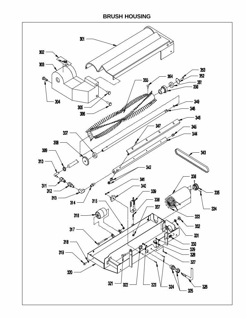
ITEM PART NO. PART DESCRIPTION QTY.301 49-9-018-1 BRUSH COVER, LONG 1302 49-9-278-1 SPRAY BAR LABEL - LABEL SET 1303 49-9-118-1 BRUSH COVER, SHORT 1304 91-2-050-0 10-24 X 3/8 TRUSS HEAD PHILLIPS MACHINE SCREW 3305 91-2-081-0 10 X 1/2 PAN HEAD PHILLIPS SHEET METAL SCREW 1306 91-2-051-0 10-24 X 1/2 TRUSS HEAD PHILLIPS MACHINE SCREW 2307 10-9-922-1 BEARING 1308 49-9-008-6 THREAD GUARD 1309 48-9-265-1 HOSE CLAMP, 3/4" 1310 27-9-179-1 90° HOSE BARB 3/8 X 1/4 NPTM 1311 49-9-129-1 MALE QUICK CONNECT 1312 49-9-128-1 FEMALE QUICK CONNECT 1313 38-9-114-1 1/4 ELBOW 90° 1314 38-9-194-1 1/4 HEX NIPPLE, BRASS 1315 91-2-089-0 1/4-20 HEX NUT WITH NY-LOK INSERT 1316 49-9-193-2 ROLLER WHEEL 1317 49-9-119-1 1/4-20 X 3 HEX BOLT (ROLLER AXLE) 1318 91-2-097-0 1/4 EXTERNAL STAR LOCK WASHER 2319 91-2-100-0 1/4-20 X 5/8 TRUSS HEAD PHILLIPS MACHINE SCREW 2320 49-9-017-3 BRUSH HOUSING FRAME 1321 49-9-117-1 3/8 X 3/4 (5/16-18) SOCKET HEAD SHOULDER SCREW 2322 48-9-083-1 STRAIN RELIEF NUT 1323 91-2-036-0 10-24 HEX NUT WITH STAR LOCK WASHER 3324 91-2-043-0 10-24 X 3/4 ROUND HEAD PHILLIPS MACHINE SCREW 2325 48-9-083-1 STRAIN RELIEF, INCLUDES NUT 1326 49-9-068-1 BRUSH MOTOR POWER CORD 1327 91-2-051-0 10-24 X 1/2 TRUSS HEAD PHILLIPS MACHINE SCREW 1328 52-9-420-1 NYLON CABLE CLAMP 1329 91-2-036-0 10-24 HEX NUT WITH STAR LOCK WASHER 1330 49-9-024-1 ADJUSTING WHEEL SPRING 1331 91-2-037-0 7/32 I.D. X 1/2 O.D. X .032/.065 THICK SAE FLAT WASHER (#10) 2332 91-2-066-0 10-32 HEX NUT WITH STAR LOCK WASHER 2333 49-9-153-1 BRUSH DRIVE MOTOR FAN, INCLUDES SET SCREW 1334 91-2-065-0 10-32 X 3/4 SET SCREW - CUP POINT 2335 49-9-049-1 BRUSH DRIVE MOTOR PULLEY 1336 49-9-132-1 BRUSH DRIVE MOTOR, 120 VOLT 1
49-9-133-1 BRUSH DRIVE MOTOR, 240 VOLT 1337 91-2-090-0 1/4-20 HEX NUT WITH NY-LOK INSERT 1338 49-9-039-1 BRUSH HOUSING LIFT CABLE 1339 49-9-042-1 BRUSH LIFT CABLE ADJUSTMENT BRACKET 1340 54-9-274-1 RECTIFIER 1341 91-2-036-0 10-24 HEX NUT WITH STAR LOCK WASHER 1342 49-9-090-1 SPRAY TIP WITH BODY 5
49-9-091-1 SPRAY TIP ONLY (8001) 548-9-211-1 SPRAY TIP SEAL GASKET, “0” RING 548-9-129-1 BODY ONLY 1
343 49-9-048-1 BRUSH DRIVE BELT 1344 49-9-004-1 SPRAY BAR 1
49-9-166-9 SPRAY BAR ASSEMBLY 1345 23-9-215-1 1/4 PIPE PLUG 1346 49-9-104-3 SPRAY BAR GUIDE 1347 91-2-051-0 10-24 X 1/2 TRUSS HEAD PHILLIPS SCREW 4348 49-9-007-1 BRUSH AXLE 1349 49-9-142-1 RETAINING RING 1350 49-9-005-1 BRUSH PULLEY 1351 10-9-992-1 BEARING 1352 34-9-049-1 RETAINING RING 1353 49-9-142-1 RETAINING RING 1354 91-2-067-0 10-32 X 5/8 FLAT HEAD PHILLIPS MACHINE SCREW 2355 49-9-003-1 BRUSH ONLY 1
49-9-165-9 BRUSH ASSEMBLY 1
BRUSH HOUSING

ITEM PART NO. PART DESCRIPTION QTY.401 91-2-036-0 10-24 HEX NUT WITH STAR LOCK WASHER 2402 91-2-073-0 10-32 X 1/2 PHILLIPS ROUND HEAD SCREW 6403 91-2-032-0 #10 SPLIT LOCK WASHER 6404 91-2-037-0 7/32 I.D. X 1/2 O.D. X .032/.065 THICK SAE FLAT WASHER (#10) 6405 91-2-059-0 10-24 X 3/8 PAN HEAD PHILLIPS THREAD CUTTING SCREW 1406 91-2-032-0 #10 SPLIT LOCK WASHER 1407 49-9-147-1 VAC MOTOR GROUND WIRE 1408 91-2-067-0 10-32 X 5/8 PHILLIPS FLAT HEAD SCREW 3409 49-9-075-1 MASTER LINK 1410 49-9-074-1 DRIVE CHAIN WITH MASTER LINK, 34 1/2 LINKS 1411 49-9-040-1 SPROCKET, DRIVE AXLE, 18 TEETH 1412 49-9-121-1 DRIVE AXLE KEY 1413 49-9-027-6 DRIVE AXLE 1414 91-2-086-0 1/4-20 X 3/8 SET SCREW 2415 27-9-011-1 WIRE, KWIK CLIP 3416 91-2-073-0 10-32 X 1/2 PHILLIPS ROUND HEAD SCREW 1417 91-2-032-0 #10 SPLIT LOCK WASHER 1418 49-9-039-1 BRUSH HOUSING LIFT CABLE 1419 91-2-041-0 10-24 X 1/2 ROUND HEAD PHILLIPS MACHINE SCREW 2420 91-2-032-0 #10 SPLIT LOCK WASHER 2421 48-9-070-3 CABLE CLAMP 1422 49-9-042-1 BRUSH LIFT CABLE ADJUSTMENT BRACKET 1423 91-2-038-0 10-24 X 3/8 ROUND HEAD PHILLIPS MACHINE SCREW 2424 49-9-113-3 AIR INTAKE SUPPORT 1425 91-2-032-0 #10 SPLIT LOCK WASHER 2426 91-2-038-0 10-24 X 3/8 ROUND HEAD PHILLIPS MACHINE SCREW 2427 49-9-026-3 MAIN FRAME, CHASSIS 1428 26-9-258-1 SWIVEL CASTER COMPLETE 2429 91-2-218-0 13/32 I.D. X 13/16 O.D. X .051/.080 THICK WASHER (WROUGHT) (3/8) 8430 91-2-210-0 3/8 SPLIT LOCK WASHER 8431 91-2-142-0 5/16-18 HEX NUT 2432 91-2-138-5 5/16-18 X 2 1/4 SET SCREW - CUP POINT 2433 91-2-226-0 3/8-16 X 1 HEX BOLT 6434 48-9-045-1 SNAP IN BUSHING 5435 48-9-008-1 VAC INTAKE TUBE 1436 48-9-047-1 GASKET, VAC INTAKE TO CHASSIS 1437 52-9-420-1 NYLON CORD CLAMP 1438 49-9-140-1 CORD, CONNECTOR TO BASE 1439 91-2-037-0 7/32 I.D. X 1/2 O.D. X .032/.065 THICK SAE FLAT WASHER (#10) 1440 91-2-032-0 #10 SPLIT LOCK WASHER 1441 91-2-041-0 10-24 X 1/2 ROUND HEAD PHILLIPS MACHINE SCREW 1442 49-9-160-9 DRIVE WHEEL ASSEMBLY WITH BEARINGS ONLY 2
49-9-006-1 8" WHEEL WITH GROOVES 249-9-034-1 BEARING, WHEEL, CLUTCH 449-9-094-6 BUSHING, WHEEL, PLATED 2
443 49-9-109-1 NYLON WASHER 6444 49-9-108-4 THRUST WASHER 2445 91-2-218-0 13/32 I.D. X 13/16 O.D. X .051/.080 THICK WASHER (WROUGHT) (3/8) 2446 91-2-210-0 3/8 SPLIT LOCK WASHER 2447 91-2-226-0 3/8-16 X 1 HEX BOLT 2448 49-9-110-1 CURVED SPRING WASHER 2449 91-2-136-5 1/4-28 X 1/4 SET SCREW 4450 49-9-055-1 BEARING, DRIVE AXLE 2451 91-2-140-0 3/8 I.D. X 7/8 O.D. X .064/.104 THICK FLAT WASHER (5/16) 2452 91-2-152-0 5/16 SPLIT LOCK WASHER 2453 91-2-172-0 5/16-18 X 1 1/4 HEX BOLT 2454 52-9-439-1 AXLE SPACER, BUMPER WHEEL 1455 27-9-028-1 BUMPER WHEEL 1456 91-2-214-0 3/8-16 HEX NUT WITH NY-LOK INSERT 1457 91-2-208-0 3/8-16 X 2 1/2 HEX BOLT 1458 49-9-278-1 BUMPER BRACKET LABEL - LABEL SET 1459 49-9-120-3 BUMPER WHEEL BRACKET 1460 49-9-117-1 3/8 X 3/4 (5/16-18) SHOCKET HEAD SHOULDER SCREW 2461 49-9-122-3 HINGE BRACKET 1462 91-2-063-7 10-24 X 1/4 SET SCREW - CUP POINT 2463 49-9-038-1 SPROCKET, GEAR DRIVE MOTOR, 12 TEETH 1464 91-2-073-0 10-32 X 1/2 PHILLIPS ROUND HEAD SCREW 4465 91-2-032-0 #10 SPLIT LOCK WASHER 4466 49-9-028-3 MOUNTING BRACKET, GEAR DRIVE MOTOR 1467 59-9-007-1 1/8 X 1/2 DRIVE MOTOR KEY 1

CHASSIS
468 49-9-060-1 GEAR DRIVE MOTOR 120 VOLT 149-9-058-1 GEAR DRIVE MOTOR 240 VOLT 1
469 48-9-006-1 COOLING DUCT, VAC MOTOR 1470 49-9-024-1 ADJUSTING WHEEL TENSION SPRING 1471 48-9-005-1 VAC MOTOR SPLASH COVER 1472 48-9-043-1 VAC MOTOR GASKET, UPPER 1473 48-9-039-9 VAC MOTOR ASSEMBLY, 120 VOLT 1
48-9-125-9 VAC MOTOR ASSEMBLY, 240 VOLT 1474 46-9-010-1 VAC MOTOR GASKET, LOWER 1475 48-9-007-1 VAC MOTOR EXHAUST CHAMBER 1476 48-9-172-1 GASKET, EXHAUST CHAMBER TO CHASSIS 1477 91-2-036-0 10-24 HEX NUT WITH STAR LOCK WASHER 3478 91-2-032-0 #10 SPLIT LOCK WASHER 1479 48-9-107-1 HEYCO STRAIN RELIEF 1480 91-2-093-0 9/32 I.D. X 5/8 O.D. X .051/.080 THICK SAE FLAT WASHER (1/4) 1481 91-2-088-0 1/4 SPLIT LOCK WASHER 1482 91-2-116-0 1/4-20 X 3/8 HEX BOLT 1483 91-2-043-0 10-24 X 3/4 ROUND HEAD PHILLIPS MACHINE SCREW 1

ITEM PART NO. PART DESCRIPTION QTY.501 27-9-179-1 90° HOSE BARB 3/8 X 1/4 NPTM 1502 49-9-147-1 GROUND WIRE, SOLENOID VALVE 1503 91-2-018-0 #8 INTERNAL STAR LOCK WASHER 1504 91-2-022-0 8-32 X 3/8 ROUND HEAD PHILLIPS MACHINE SCREW 1505 38-9-194-1 1/4 HEX NIPPLE, BRASS 1506 43-9-061-1 1/4 NPT STREET “T” 1507 38-9-194-1 1/4 HEX NIPPLE, BRASS 1508 35-9-051-1 FEMALE QUICK CONNECT, ACCESSORY SOLUTION 1509 91-2-265-0 1/2-13 X 2 1/14 HEX BOLT 1510 23-9-146-6 PIVOT SPACER 1511 23-9-194-1 BALL JOINT, VAC SHOE PIVOT 1512 49-9-039-1 LIFT CABLE, BRUSH HOUSING 1513 49-9-099-1 SPRAY TIP 1514 49-9-126-1 ACCESSORY SPRAY GUN ONLY 1
49-9-172-9 ACCESSORY SPRAY GUN WITH HOSE 1515 48-9-085-1 CORD CLAMP 1516 35-9-075-1 MALE QUICK CONNECT, ACCESSORY SOLUTION 1517 49-9-284-1 SOLUTION HOSE FOR SPRAY GUN 1518 91-2-226-0 3/8-16 X 1 HEX BOLT 1519 91-2-210-0 3/8 SPLIT LOCK WASHER 1520 49-9-045-3 VAC SHOE LIFT BRACKET 1521 91-2-242-0 1/2 SPLIT LOCK WASHER 1522 49-9-053-6 VAC SHOE PIVOT ARM 1523 49-9-072-3 COVER PLATE, VAC SHOE 1524 91-2-245-0 17/32 I.D. X 1 1/16 O.D. X .047/.121 THICK SAE FLAT WASHER (1/2) 1525 49-9-054-2 KNOB FOR VAC SHOE 1526 91-2-109-0 1/4-20 X 1/2 TRUSS HEAD PHILLIPS MACHINE SCREW 1527 91-2-097-0 1/4 EXTERNAL STAR LOCK WASHER 11528 49-9-071-1 VAC SHOE GASKET 1529 49-9-089-1 VAC SHOE WEIGHT 2530 49-9-009-3 VAC SHOE CASTING 1
49-9-163-9 VAC SHOE ASSEMBLY 1531 49-9-278-1 VAC SHOE DISCONNECT LABEL - LABEL SET 1532 91-2-155-0 5/16 X 3/8 (1/4-20) SOCKET HEAD SHOULDER BOLT 1533 91-2-249-5 1/2-13 THIN HEX NUT WITH NY-LOK INSERT 1534 49-9-046-3 LIFT BRACKET SUPPORT 1535 91-2-091-0 1/4-20 HEX NUT WITH STAR LOCK WASHER 1536 23-9-146-6 PIVOT SPACER 1537 49-9-117-1 3/8 X 3/4 (5/16-18) SOCKET HEAD SHOULDER BOLT 2538 49-9-278-1 BRUSH COVER LABEL - LABEL SET 1539 49-9-167-9 BRUSH HOUSING ASSEMBLY 1540 49-9-026-3 MAIN FRAME, CHASSIS 1541 48-9-459-1 SOLUTION PUMP 100 PSI, 120 VOLT 1
38-9-201-1 SOLUTION PUMP 100 PSI, 240 VOLT 1542 48-9-157-1 SOLUTION HOSE, SOLUTION TANK TO PUMP 1543 48-9-265-1 HOSE CLAMP 3/4" 1544 48-9-188-1 90° HOSE BARB 3/8 NPTM 1545 91-2-037-0 7/32 I.D. X 1/2 O.D. X .032/.065 THICK SAE FLAT WASHER (#10) 1546 91-2-032-0 #10 SPLIT LOCK WASHER 4547 91-2-045-0 10-24 X 1 ROUND HEAD PHILLIPS MACHINE SCREW 4548 49-9-131-1 SOLUTION HOSE, SOLENOID TO SPRAY MANIFOLD 1549 48-9-265-1 HOSE CLAMP 3/4" 1550 48-9-478-1 SOLENOID VALVE 120 VOLT 1
48-9-127-1 SOLENOID VALVE 240 VOLT 1551 48-9-021-1 BRASS BUSHING, 1/4F X 3/8 NPTM 1

VAC SHOE
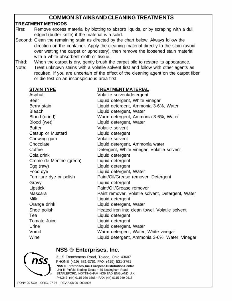
COMMON STAINS AND CLEANING TREATMENTSTREATMENT METHODSFirst: Remove excess material by blotting to absorb liquids, or by scraping with a dull
edged (butter knife) if the material is a solid.Second: Clean the remaining stain as directed by the chart below. Always follow the
direction on the container. Apply the cleaning material directly to the stain (avoidover wetting the carpet or upholstery), then remove the loosened stain materialwith a white absorbent cloth or tissue.
Third: When the carpet is dry, gently brush the carpet pile to restore its appearance.Note: Treat unknown stains with a volatile solvent first and follow with other agents as
required. If you are uncertain of the effect of the cleaning agent on the carpet fiberor die test on an inconspicuous area first.
STAIN TYPE TREATMENT MATERIALAsphalt Volatile solvent/detergentBeer Liquid detergent, White vinegarBerry stain Liquid detergent, Ammonia 3-6%, WaterBleach Liquid detergent, WaterBlood (dried) Warm detergent, Ammonia 3-6%, WaterBlood (wet) Liquid detergent, WaterButter Volatile solventCatsup or Mustard Liquid detergentChewing gum Volatile solventChocolate Liquid detergent, Ammonia waterCoffee Detergent, White vinegar, Volatile solventCola drink Liquid detergentCreme de Menthe (green) Liquid detergentEgg (raw) Liquid detergentFood dye Liquid detergent, WaterFurniture dye or polish Paint/Oil/Grease remover, DetergentGravy Liquid detergentLipstick Paint/Oil/Grease removerMascara Paint remover, Volatile solvent, Detergent, WaterMilk Liquid detergentOrange drink Liquid detergent, WaterShoe polish Heated iron into clean towel, Volatile solventTea Liquid detergentTomato Juice Liquid detergentUrine Liquid detergent, WaterVomit Warm detergent, Water, White vinegarWine Liquid detergent, Ammonia 3-6%, Water, Vinegar
PONY 20 SCA ORIG. 07-97 REV A 08-00 9094906
NSS ® Enterprises, Inc.3115 Frenchmens Road, Toledo, Ohio 43607PHONE (419) 531-3761 FAX (419) 531-3761NSS ® Enterprises, Inc. European Distribution CentreUnit II, Pinfold Trading Estate * 55 Nottingham RoadSTAPLEFORD, NOTTINGHAM NG9 8AD ENGLAND U.K.PHONE: (44) 0115 939 1568 * FAX: (44) 0115 949 0615