Polymer microfluidic systems for sample preparation for bacterial ...
79
Polymer microfluidic systems for sample preparation for bacterial detection Mikael Hillmering Doctoral Thesis Stockholm 2014
Transcript of Polymer microfluidic systems for sample preparation for bacterial ...

Polymer microfluidic systems for samplepreparation for bacterial detection
Mikael Hillmering
Doctoral Thesis
Stockholm 2014

The front cover photographs show microfluidic systems and features. Top left: Across-section of a 35 µm thin and 100 mm2 large membrane in the polymer PDMS.Top middle: High aspect ratio pillars (400 µm tall, 50 µm diameter) produced in thepolymer OSTE using photolithography. Top right: Focusing of particles inmicrofluidic channels using inertial microfluidics. Bottom: A lab-on-a-chip devicefor DNA amplification and detection.
KTH Royal Institute of TechnologyTRITA-EE 2014:038 Department of Micro and NanosystemsISSN 1653-5146 SE-100 44 StockholmISBN 978-91-7595-244-4 SWEDEN
Akademisk avhandling som med tillstånd av Kungliga Tekniska Högskolanframlägges till offentlig granskning för avläggande av teknologie doktorsexamen ielektrisk mätteknik, den 3 oktober 2014 kl 10:00 i Oskar Klein-auditoriet,Roslagstullsbacken 21, Stockholm.
Thesis for the degree of Doctor of Philosophy in Electrical Engineering at the RoyalInstitute of Technology, Stockholm, Sweden, 2014.
© Mikael Hillmering 2014
E-mail: [email protected]
Print: Universitetsservice US AB, Stockholm 2014.

iii
Abstract
Sepsis, caused by blood stream infection, is a very serious health condition thatrequires immediate treatment using antibiotics to increase the chances for patientsurvival. A high prevalence of antibiotic resistance among infected patients requiresstrong and toxic antibiotics to ensure effective treatment. A rapid diagnostic devicefor detection of antibiotic resistance genes in pathogens in patient blood would enablean early change to accurate and less toxic antibiotics. Although there is a pressingneed for such devices, rapid diagnostic tests for sepsis do not yet exist.
In this thesis, novel advances in microfabrication and lab-on-a-chip devices arepresented. The overall goal is to develop microfluidics and lab-on-a-chip systems forrapid sepsis diagnostics. To approach this goal, novel manufacturing techniques formicrofluidics systems and novel lab-on-a-chip devices for sample preparation havebeen developed.
Two key problems for analysis of blood stream infection samples are that lowconcentrations of bacteria are typically present in the blood, and that separation ofbacteria from blood cells is difficult. To ensure that a sufficient amount of bacteria isextracted, large sample volumes need to be processed, and bacteria need to be isolatedwith high efficiency. In this thesis, a particle filter based on inertial microfluidicsenabling high processing flow rates and integration with up- and downstream processesis presented.
Another important function for diagnostic lab-on-a-chip devices is DNA amplifi-cation using polymerase chain reaction (PCR). A common source of failure for PCR-on-chip is the formation of bubbles during the analysis. In this thesis, a PCR-on-chipsystem with active degassing enabling fast bubble removal through a semipermeablemembrane is presented.
Several novel microfabrication methods were developed. Novel fabrication tech-niques using the polymer PDMS that enable manufacturing of complex lab-on-a-chipdevices containing 3D fluidic networks and fragile structures are presented. Also,a mechanism leading to increased accuracy in photopatterning in thiol-enes, whichenables rapid prototyping of microfluidic devices, is described. Finally, a novel flexibleand gas-tight polymer formulation for microfabrication is presented: rubbery OSTE+.
Together, the described achievements lead to improved manufacturing methodsand performances of lab-on-a-chip devices, and may facilitate future development ofdiagnostic devices.
Mikael Hillmering, [email protected] , Micro and Nanosystems, School of ElectricalEngineering, KTH Royal Institute of Technology, Stockholm, Sweden


v
Sammanfattning
Sepsis, orsakad av t.ex. blodförgiftning, är ett mycket allvarligt hälsotillstånd somkräver omedelbar behandling med antibiotika för att öka patientens chans till över-levnad. På grund av den höga förekomsten av antibiotikaresistens hos bakterier ipatienter används giftigare läkemedel för att säkerställa effektiv behandling. Om detfanns ett diagnostiskt verktyg för att snabbt kunna detektera gener för antibiotikare-sistens hos patogener i blodet, skulle behandlingen snabbare kunna övergå till mildareoch mer specifika antibiotika.
Denna avhandling presenterar nya framsteg inom mikrofabrikation och mikrochipför provanalys, s.k. lab-on-a-chip. Det övergripande målet för arbetet är att utvecklamikrofluidik och lab-on-a-chip-system för snabb diagnostik av sepsis och blodförgift-ning. För att komma närmare en lösning presenteras här nya tillverkningstekniker förmikrofluidik-system, samt nya lab-on-a-chip-komponenter för provberedning.
En patient med blodförgiftning har ofta mycket låga koncentrationer av patogenersåsom bakterier i blodet. För att säkerställa att en tillräcklig mängd bakterier följermed i ett prov måste idag provvolymer på >1 ml bearbetas, vilket är svårt att genom-föra på kort tid med dagens metoder inom microfluidik. En annan komplicerandefaktor är att bakterier och blodceller har ungefär samma storlek. Detta försvårarseparation av bakterier från blod och kräver högupplösta metoder för separation. Idenna avhandling presenteras ett partikelfilter som baseras på höga flödeshastigheteri ett tredimensionellt fluidiknätverk, som kan integreras med andra processer på ettlab-on-a-chip.
En annan viktig delfunktion för ett lab-on-a-chip för sepsis-diagnostik är att frånnågra få kopior bakterie-DNA få fram miljontals kopior av antibiotikaresistensgenersom sedan kan detekteras, s.k. amplifiering av DNA. I denna avhandling användespolymerase chain reaction (PCR). Ett vanligt problem i mikrofluidik, särskilt PCR,är att uppvärmning leder till att gasbubblor bildas. För att lösa detta problempresenteras i denna avhandling ett avgasningssystem, som suger ut bubblor ur PCR-kammaren genom ett semipermeabelt membran.
I avhandlingen presenteras också flera nya metoder för mikrofabrikation. Kom-plexa mikrostrukturer innehållande tredimensionella fluidiknätverk och sköra struk-turer, såsom membranet som används för bubbelborttagning, är svåra att framställa.För att möjliggöra tillförlitlig tillverkning av sådana strukturer har nya tillverkn-ingstekniker utveklats för en standardpolymer inom akademin: PDMS. Dessutomhar nya tekniker och material utvecklats för mikrofabrikation och chiptillverkningi en ny polymer-plattform som är speciellt utvecklad för lab-on-a-chip: OSTE. En

mekanism som leder till förbättrad fotomönstring av OSTE beskrivs, vilken leddetill utvecklingen av en snabb metod för prototyptillverkning av mikrofluidiksystem iOSTE. Slutligen presenteras en ny formulering av OSTE som leder till ett gummiartatoch gastätt material för mikrofabrikation.
Resultaten som presenteras i denna avhandling har lett till förbättrade tillverkn-ingsmetoder och lab-on-a-chip-system, som tillsammans har möjligheten att förenklaframställningen av nya verktyg och metoder för medicinsk diagnostisk.

“Being a scientist means living on the borderline between yourcompetence and your incompetence. If you always feel competent, youaren’t doing your job.”
- Carlos Bustamante, UC-Berkeley
“One of the great things about books is sometimes there are somefantastic pictures.”
- George W. Bush


ix
Contents
List of publications xi
1 Introduction 11.1 Objectives of this thesis . . . . . . . . . . . . . . . . . . . . . . . . . . 11.2 Summary of contributions . . . . . . . . . . . . . . . . . . . . . . . . 11.3 Structure of the thesis . . . . . . . . . . . . . . . . . . . . . . . . . . . 2
2 Background 52.1 The clinical need for improved sepsis diagnostics . . . . . . . . . . . . 5
2.1.1 Rapid diagnostics and point-of-care devices . . . . . . . . . . . 72.2 Introduction to microfluidics . . . . . . . . . . . . . . . . . . . . . . . 82.3 Introduction to lab-on-a-chip technology . . . . . . . . . . . . . . . . 92.4 A lab-on-a-chip for sepsis diagnostics . . . . . . . . . . . . . . . . . . . 10
2.4.1 Bacteria isolation from whole blood . . . . . . . . . . . . . . . 112.4.2 DNA extraction and purification . . . . . . . . . . . . . . . . . 112.4.3 Amplification of resistance genes from bacteria . . . . . . . . . 112.4.4 Detection of resistance genes . . . . . . . . . . . . . . . . . . . 122.4.5 Instrumentation . . . . . . . . . . . . . . . . . . . . . . . . . . 12
2.5 Rapid prototyping of lab-on-a-chip devices . . . . . . . . . . . . . . . 132.5.1 Requirements on the prototyping process for the Intopsens
device . . . . . . . . . . . . . . . . . . . . . . . . . . . . . . . . 142.5.2 Material choices for microstructuring: PDMS and OSTE . . . . 14
2.6 Summary . . . . . . . . . . . . . . . . . . . . . . . . . . . . . . . . . . 15
3 Novel PDMS fabrication methods 173.1 Introduction to rapid prototyping using PDMS . . . . . . . . . . . . . 17
3.1.1 Multilevel structures with 3D fluidics . . . . . . . . . . . . . . 173.1.2 Fabrication of fragile layers . . . . . . . . . . . . . . . . . . . . 18
3.2 Novel PVA-based microfabrication methods . . . . . . . . . . . . . . . 193.2.1 PVA as sacrificial material . . . . . . . . . . . . . . . . . . . . 193.2.2 Floatation transfer . . . . . . . . . . . . . . . . . . . . . . . . 213.2.3 Local polymerization inhibition for 3D fluidics . . . . . . . . . 223.2.4 Double-sided molding . . . . . . . . . . . . . . . . . . . . . . . 22
3.3 Summary and outlook . . . . . . . . . . . . . . . . . . . . . . . . . . . 23

x CONTENTS
4 Novel OSTE fabrication methods 274.1 Introduction to OSTE polymers . . . . . . . . . . . . . . . . . . . . . . 274.2 Novel methods using photolithography and OSTE . . . . . . . . . . . 29
4.2.1 A depletion mechanism in photopatterning of thiol-enes . . . . 294.2.2 Rapid prototyping of OSTE microchips using photolithography 304.2.3 Rubbery OSTE+ for lab-on-a-chip . . . . . . . . . . . . . . . . 30
4.3 Summary and outlook . . . . . . . . . . . . . . . . . . . . . . . . . . . 31
5 Novel LOC systems for sepsis diagnostics 355.1 Inertial microfluidics for sample preparation . . . . . . . . . . . . . . 35
5.1.1 Introduction to focusing of particles using inertial microfluidics 355.1.2 Challenges with inertial microfluidics for sepsis diagnostics . . 365.1.3 High flow filtration using inertial focusing and 3D fluidics . . . 365.1.4 Summary and outlook . . . . . . . . . . . . . . . . . . . . . . . 38
5.2 DNA amplification using PCR with bubble removal . . . . . . . . . . . 395.2.1 Introduction to PCR-on-chip . . . . . . . . . . . . . . . . . . . 395.2.2 Molecular transport through PDMS membranes . . . . . . . . 405.2.3 Gas bubble removal through PDMS/Teflon membranes during
PCR . . . . . . . . . . . . . . . . . . . . . . . . . . . . . . . . . 415.2.4 Summary and outlook . . . . . . . . . . . . . . . . . . . . . . . 43
5.3 Leak-tight pneumatic microvalves . . . . . . . . . . . . . . . . . . . . . 445.3.1 Introduction to pneumatic microvalves . . . . . . . . . . . . . 445.3.2 Leak-tight vertical membrane microvalves . . . . . . . . . . . . 445.3.3 Summary and outlook . . . . . . . . . . . . . . . . . . . . . . . 44
5.4 Integration of components into a lab-on-a-chip . . . . . . . . . . . . . 455.4.1 Introduction to integration . . . . . . . . . . . . . . . . . . . . 455.4.2 Integration of on-chip PCR with a DNA array . . . . . . . . . 455.4.3 Packaging of lab-on-a-chip devices . . . . . . . . . . . . . . . . 465.4.4 Summary and outlook . . . . . . . . . . . . . . . . . . . . . . . 47
6 Conclusions 49
Summary of appended papers 51
Acknowledgements 53
References 63
Paper reprints 65

xi
List of publications
The thesis is based on the following papers presented in international peer-reviewedjournals and international reviewed conference proceeding:
1. ”Fabrication and transfer of fragile 3D PDMS microstructures”J. Mikael Karlsson, Tommy Haraldsson, Carl Fredrik Carlborg, Jonas Hans-son, Aman Russom, and Wouter van der WijngaartJournal of Micromechanics and Microengineering, vol. 22, no. 8, pp. 085009,July 2012.
2. ”Low-stress transfer bonding using floatation”J. Mikael Karlsson, Tommy Haraldsson, Carl Fredrik Carlborg, and Woutervan der WijngaartJournal of Micromechanics and Microengineering, vol. 22, no. 7, pp. 075005,May 2012.
3. ”Leak-tight vertical membrane microvalves in PDMS enabled by a novel 3Dmanufacturing process”J. Mikael Karlsson, Jonas Hansson, Tommy Haraldsson, and Wouter van derWijngaartManuscript.
4. ”Off-stoichiometry improves photopatterning of thiol-enes through diffusion-induced monomer depletion”J. Mikael Karlsson, Gaspard Pardon, Alexander Vastesson, Omkar Supekar,Carl Fredrik Carlborg, Wouter van der Wijngaart, and Tommy HaraldssonSubmitted August 2014.
5. ”Rapid mold-free manufacturing of microfluidic devices with robust and spa-tially directed surface modifications”Gaspard Pardon, Farizah Saharil, J. Mikael Karlsson, Omkar Supekar, CarlFredrik Carlborg, Wouter van der Wijngaart, and Tommy HaraldssonMicrofluid Nanofluid, pp. 1-7, February 2014.
6. ”Low gas permeable and non-absorbent rubbery OSTE+ for pneumatic mi-crovalves”Jonas Hansson, J. Mikael Karlsson, Carl Fredrik Carlborg, Wouter van der

xii LIST OF PUBLICATIONS
Wijngaart, and Tommy HaraldssonProceeding of the 27th Int. Conf. on Micro Electro Mechanical Systems, SanFrancisco, USA, pp. 987-990, January 2014.
7. ”Inertial microfluidics in parallel channels for high-throughput applications”Jonas Hansson, J. Mikael Karlsson, Tommy Haraldsson, Hjalmar Brismar,Wouter van der Wijngaart, and Aman RussomLab Chip, vol. 12, pp. 4644-4650, July 2012.
8. ”Active liquid degassing in microfluidic systems”J. Mikael Karlsson, Muriel Gazin, Sanna Laakso, Tommy Haraldsson, SurbhiMalhotra-Kumar, Minna Mäki, Herman Goossens, and Wouter van der Wijn-gaartLab Chip, vol. 13, pp. 4366-73, August 2013.
The contribution of Mikael Hillmering, formerly Mikael Karlsson, to the differentpublications:
Paper 1: Major part of design, experiments and writingPaper 2: Major part of design, experiments and writingPaper 3: Major part of design, experiments and writingPaper 4: Major part of design, experiments and writingPaper 5: Part of design, fabrication, experiments and writingPaper 6: Part of experiments and writingPaper 7: Major part of fabrication, part of experiments and writingPaper 8: Major part of design, all fabrication, major part of experiments and writing

LIST OF PUBLICATIONS xiii
The work presented in this thesis has also been presented in the following internationalreviewed conference proceedings:
1. ”Transfer bonding of microstructures and fabrication of fragile PDMS mem-branes using water dissolvable film”J. Mikael Karlsson, Tommy Haraldsson, Carl Fredrik Carlborg, Göran Stemme,and Wouter van der WijngaartProceedings of the 14th Int. Conf. on Miniaturized Systems for Chemistry andLife Sciences (µTAS), Groningen, Netherlands, pp. 1202-1204, October 2010.
2. ”On-chip liquid degassing with low water loss”J. Mikael Karlsson, Tommy Haraldsson, Niklas Sandström, Göran Stemme,Aman Russom, and Wouter van der WijngaartProceedings of the 14th Int. Conf. on Miniaturized Systems for Chemistry andLife Sciences (µTAS), Groningen, Netherlands, pp. 1790-1792, October 2010.
3. ”Low-stress wafer-level transfer bonding of polymer layers using floatation”J. Mikael Karlsson, Tommy Haraldsson, Carl Fredrik Carlborg, and Woutervan der WijngaartProceedings of the 16th Int. Conf. on Solid-State Sensors, Actuators andMicrosystems (Transducers), Beijing, China, pp. 418-421, June 2011.
4. ”Inertial particle focusing in parallel microfluidic channels for high-throughputfiltration”Jonas Hansson, J. Mikael Karlsson, Tommy Haraldsson, Wouter van derWijngaart, and Aman RussomProceedings of the 16th Int. Conf. on Solid-State Sensors, Actuators andMicrosystems (Transducers), Beijing, China, pp. 1777-1780, June 2011, oralpresentation.
5. ”PCR on a PDMS-based microchip with integrated bubble removal”J. Mikael Karlsson, Tommy Haraldsson, Sanna Laakso, Akseli Virtanen,Minna Mäki, Gerry Ronan, and Wouter van der WijngaartProceedings of the 16th Int. Conf. on Solid-State Sensors, Actuators andMicrosystems (Transducers), Beijing, China, pp. 2215-2218, June 2011.
6. ”High-resolution micropatterning of off-stoichiometric thiol-enes (OSTE) via anovel lithography mechanism”J. Mikael Karlsson, Carl Fredrik Carlborg, Farizah Saharil, Fredrik Forsberg,Frank Niklaus, Wouter van der Wijngaart and Tommy HaraldssonProceedings of the 16th Int. Conf. on Miniaturized Systems for Chemistryand Life Sciences (µTAS), Okinawa, Japan, pp. 225-227, October 2012, oralpresentation.
7. ”A double-sided micromolding process for reproducible manufacturing of thinlayers and 3D microchannels in PDMS”J. Mikael Karlsson, Tommy Haraldsson, Carl Fredrik Carlborg, and Wouter

xiv LIST OF PUBLICATIONS
van der WijngaartProceedings of the 16th Int. Conf. on Miniaturized Systems for Chemistry andLife Sciences (µTAS), Okinawa, Japan, pp. 659-661, October 2012.

1
Chapter 1
Introduction
1.1 Objectives of this thesisThe work summarized in this thesis has been part of an EU project, Intopsens, whichaimed at developing a rapid diagnostic device for sepsis and blood stream infections.The overall goal of this thesis is to improve lab-on-a-chip technology for diagnostics.More specifically, the two main objectives are:
• Development of sample preparation devices for clinical diagnostics.Lab-on-a-chip technology has the potential to enable rapid diagnostics for sep-sis and blood stream infection, but requires development of novel devices forbacteria isolation from blood and reliable DNA amplification.
• Development of novel microfabrication techniques using polymers.Improvements of microfabrication techniques to produce lab-on-a-chip devicesin polymers will enable robust and cost-efficient manufacturing techniques ofnovel and more advanced devices suitable for clinical diagnostics.
1.2 Summary of contributionsIn pursuit of the objectives of this thesis, several contributions of novel manufac-turing methods and lab-on-a-chip components were made (Figure 1.1). The maincontributions from the papers presented can be summarized as follows:
• Improvements in PDMS manufacturing to enable fragile layers, 3Dfluidic networks and vertical membrane microvalves.Novel methods to produce fragile structures in chip- and wafer-sized polymerlayers were developed (Papers 1 and 2 ). A method enabling fragile structuresin combination with 3D fluidic networks was developed (Paper 1 ). A methodfor microstructuring on two sides of a layer, facilitating alignment and enablingmonolithic 3D fluidic layers and vertical membrane microvalves was developed(Paper 3 ). These manufacturing methods are presented in Chapter 3 and themicrovalves in Section 5.3.

2 1.3. STRUCTURE OF THE THESIS
• Development of thiol-ene polymer formulations for improved pho-topatterning and rubbery properties.A mechanism leading to improved patterning using photolithography in off-stoichiometry thiol-enes was described (Paper 4 ). The mechanism was usedto develop a full protocol for rapid manufacturing of microfluidic chips (Paper5 ). Also, a novel rubbery OSTE+ material with low sample absorption andgas permeability properties, enabling manufacturing of gas-tight pneumaticvalves was developed (Paper 6 ). These manufacturing methods and materialdevelopments are presented in Chapter 4.
• The introduction of a microfluidic method enabling particle filtrationwith high throughput.A method for efficient particle filtration at high flow rates was developed (Paper7 ). The filter is based on inertial focusing in parallel microchannels connectedby 3D fluidic networks, making the device suitable for integration into LOCdevices. The filtration principle is described in Section 5.1.
• A microsystem with fast removal of gas bubbles from microchannelsenabling bubble-free PCR-on-chip with low water loss.The first solution for degassing of liquids in microfluidic systems that alsofunction at elevated temperatures with low water loss was developed (Paper8 ). The method is described in Section 5.2.
1.3 Structure of the thesisChapter 1 gives an introduction to the objectives, novelty claims and the generalstructure of the thesis. Chapter 2 gives the background to the work performed, witha presentation of the clinical need for sepsis and blood stream infection diagnostics,the technologies used and the research project in which the work summarized in thisthesis was performed. In Chapter 3, improvements in manufacturing of microchipsusing a standard academic manufacturing polymer, PDMS, are presented. In Chapter4, novel techniques and materials for microfabrication and chip manufacturing usinga novel polymers platform specifically developed for lab-on-a-chip technology, OSTE,are presented. In Chapter 5, novel techniques and lab-on-a-chip components arepresented, including a particle filtration system based on inertial focusing, a DNAamplification system with bubble removal, vertical membrane microvalves, and endswith a section about integration of components to form a lab-on-a-chip. Chapter 6contains the conclusions of the thesis.

CHAPTER 1. INTRODUCTION 3
70µm
Bacteria isolation
from whole blood
Patient blood sample
containing bacteria
Detection and readout
of resistance genes
Extraction and puri!cation
of bacterial DNADNA ampli!cation
Contributions:
Contributions:
Objective: Development of novel microfabrication techniques using polymers.
Solution strategy for rapid diagnostics for sepsis and blood stream infections in the Intopsens research project:
Objective: Development of sample preparation devices for clinical diagnostics.
Paper 7:
The !rst microsystem enabling high "ow !ltration using inertial focusing
and parallelization that is suitable for lab-on-a-chip integration.
Paper 8:
The !rst microsystem enabling bubble removal with
low water loss enabling bubble-free PCR-on-chip.
Bubble-free after
70 s degassing
Bubbles forming
in micro-PCR
Gas pocket PCR sample
First material strategy (Chapter 3): Poly(dimethylsiloxane (PDMS) microfabrication
700 µm
35 µm
5 mm
Membrane for valving
Liquid "owGas pressure
Papers 1-3:
Novel methods to produce fragile membranes in combination with 3D "uidic networks,
to enable parallelization of inertial focusing and membrane for degassing of PCR.
Paper 3:
Double-sided molding enabling the !rst leak-
tight vertical membrane microvalve (Chapter 5).
0 kPa
300 kPa
Second material strategy (Chapter 4): O#-stoichiometry thiol-ene (OSTE) microfabrication
Paper 4:
Increased photopatterning accuracy in
OSTE, enabling...
Paper 5:
...rapid prototyping of
micro"uidic chips.
Paper 6:
Rubbery OSTE+: a gas-tight, low-absorbing
polymer for rapid prototyping.
200 kPa0 kPa
100µm
Stoichiometric thiol-ene O!-stoichiometric thiol-ene
Strategy in Intopsens:
Inertial micro"uidics
Strategy in Intopsens:
PCR-on-chip
Figure 1.1. Overview of objectives and contributions.

4 1.3. STRUCTURE OF THE THESIS

5
Chapter 2
Background: Lab-on-a-chip for sepsisdiagnostics
In this chapter, a background to the work presented in this thesis is given. In Section2.1, the clinical need the research aims to solve is described. In Sections 2.2-2.3,background to microfluidics and lab-on-a-chip technology is presented. In Section2.4, the strategies chosen by the consortium of the research project Intopsens aredescribed, which constituted the starting point of the work presented in Chapters3-5. In Section 2.5, a background to rapid prototyping of microfluidic systems usingpolymers is introduced.
2.1 The clinical need for improved sepsis diagnosticsConsider the following scenario: A patient arrives at a hospital with low blood pressureand fever, and shows signs of dizziness and confusion. After examination, a doctordraws the conclusion that the patient has systemic inflammatory response syndrome(SIRS), a whole-body inflammatory state which can be caused by an infection, suchas blood stream infection (BSI).
BSI means that pathogens such as bacteria, viruses or fungi have entered the bloodstream. If BSI or some other infection is suspected to be the cause of SIRS, the patientis diagnosed with sepsis, which is a serious threat to human health. In fact, every hourapproximately 1000 people die from sepsis worldwide [1] and approximately 135’000people in Europe per year [2].
The doctor suspects that the patient has sepsis, takes blood samples and immedi-ately starts intravenous antibiotic therapy of the patient. Since it is unknown whichantibiotic will be efficient, a statistically favored choice is made, so-called empirictherapy, typically involving broad-spectrum antibiotics. Unfortunately, this treatmentis affected by one of the most serious threats to human health of our time [3]: antibioticresistance.
In 2012, methicillin-resistant Staphylococcus aureus (MRSA), which by the expres-sion of the gene mecA is resistant to the most commonly used class of antibiotics [4],

6 2.1. THE CLINICAL NEED FOR IMPROVED SEPSIS DIAGNOSTICS
beta-lactams, was found in >50 % of invasive isolates (blood or cerebrospinal fluidsamples) in some European countries [5]. As infectious pathogens become moreresistant to the antibiotics used today, the empiric therapy of patients is adjustedtowards more toxic compounds to ensure effective treatment. An example is thereintroduction in some countries of the antibiotic colistin as a standard therapeutic [6],which used to be regarded as a last-resort treatment due to its toxicity for the patient.
Another drawback of using broad-spectrum antibiotics is that the balance ofbacteria in the normal flora is disrupted and antibiotic resistant bacteria are given theopportunity to colonize, giving the user a reduced chance of survival if these bacteriacause an infection. However, the grave condition of sepsis calls for treatment usingwhatever works, to reduce the risk of having the patient enter the life-threateningstates of severe sepsis, septic shock or multiple organ dysfunction syndrome (MODS).The survival rate among patients drops dramatically, from 80 % to 10 %, duringthe first 24 hours from showing the first signs of septic shock, making it critical tominimize the delay in finding effective antibiotics [7].
The blood samples from the patient are sent to a microbiological analysis lab forculturing and antibiotic susceptibility tests, to see which antibiotics the pathogens arenot resistant against.
The blood samples consist of 2-3 culture sets, each with a volume of 20-30 ml foraerobic and anaerobic growth, with higher volumes associated with higher detectionrate [8]. In successful cases, there will be a positive answer of antibiotic suscepti-bility within 48-96 hours [9], but the overall positivity of cultures may be as low as30-40 % [8].
In the meantime, the patient is declared having severe sepsis by showing signs oforgan dysfunctions, and is moved to the intensive care unit (ICU) to keep vital organsfunctioning and to enable regulation of blood pressure while the infection is treated.After the standard delay of three days [9], the culturing and antibiotic susceptibilitytests get positive and antibiotic de-escalation can be done.
De-escalation means moving from broad-spectrum treatment to a streamlinedantibiotic therapy, reduced concentrations, or discontinuation, which shortens unnec-essary antibiotic exposure and reduce the use of wrong antibiotics. Also, de-escalationhas been associated with reduced mortality rates among patients with sepsis, whichcan be partly explained by the use of less toxic antibiotics and increased use of targetedand active agents [9].
Although sepsis is one of the leading causes of death in ICUs in the developed world[10], our patient is lucky and responds well to the treatment. Apart from some resistantbacteria in his body and some side effects of the strong antibiotics, he recovers welland leaves the hospital.
The struggles and challenges related to antibiotic resistance and de-escalationfor sepsis patients are currently of high importance and there is an urgent need forimmediate actions. It is known that antibiotics are heavily overused [11], which hasquickly led us towards a global challenge. In April 2014, the WHO warned thatthe world is “headed for a post-antibiotic era”, in which pneumonia will be highlydangerous, surgeries will have increased mortality rates, and diarrhea can become

CHAPTER 2. BACKGROUND 7
fatal [3]. The spreading rate of antibiotic resistance genes has to be reduced and neweffective alternatives are needed. In addition, to circumvent the intricate problems ofresistance, we need to learn how to minimize its development and change our routinesaccordingly. For this, the world needs new diagnostic tools that can rapidly give usdetailed information on antibiotic susceptibility.
2.1.1 Rapid diagnostics and point-of-care devices
Point-of-care (POC) devices are tools that give test results close to the patient, forexample home tests or rapid devices that facilitate diagnostics during a doctor’s visit.A rapid, accurate and specific POC device for sepsis has the potential to greatlyreduce the delay to accurate antibiotic treatments, and thereby lead to large costsavings, reduced patient length of stays in hospitals and increase survival rates. Witha POC for sepsis, the story would take a different turn:
Now, imagine another patient entering the hospital. The doctor suspects the patientsuffers from SIRS and takes a blood sample. A machine is standing on a nearby desk,into which the doctor puts a small device and adds some of the blood. Within a fewminutes, the device indicates that the patient has blood stream infection and givesinformation about which specific antibiotics will be efficient against the infectiouspathogens.
A diagnostic test that give information about antibiotic suscpetibility prior thefirst dose would need to be finished within a few minutes. The second dose will begiven after up to 6 hours later, which is a more realistic target for the development ofa first rapid diagnostic test. However, if the test is to be analysed in a hospital lab,the logistics of sampling and analysis requires such a test to be finished within 1-2hours.
Today, no POC for sepsis diagnostics exist, and much development is still neededto enable such a system. There are many challenges, such as that the bacteria loadis often below 10 colony forming units (CFU) per ml for adults [8], many antibioticresistance genes have to be detected simultaneously and a short procedure turn-aroundtime is needed. For sepsis diagnostics, the need for rapid results is currently muchgreater than portability or the fact that the analysis is performed in a doctor’s office.Therefore, a laboratory process that is a rapid alternative to culturing would be agreat improvement, even if it does not result in a POC device. Alternative laboratorytests for BSI that omit the need for culturing exist. These tests are all nucleic acidtests (NAT) and based on DNA amplification using polymerase chain reaction (PCR):SepsiTest (Molzym), VYOO (SIRS-Lab), LightCycler SeptiFast (Roche Diagnostics),Plex-ID (Abbot), BioSeeq (Smith detection) and MagicPlex Sepsis Test (SeeGene).However, these methods suffer from drawbacks such as limited resistance gene detec-tion, laborious work, low sensitivity, high cost and long analysis times [8]. What isneeded for sepsis diagnostics is a rapid, multiplex, sensitive, automated method thatis easy to use.

8 2.2. INTRODUCTION TO MICROFLUIDICS
2.2 Introduction to microfluidicsMicrofluidics is the field of science and technology of systems for processing or manip-ulation of fluids utilizing miniaturization effects in channels with dimensions on themicrometer scale. Since volume (length^3) decreases faster than surface (length^2)during downscaling (reduced length), surface effects such as surface tension becomedominating over volume and mass effects such as gravity at the small scale. Also,the surface to volume ratio increases at the small scale, which leads to significantliquid-surface interactions, which causes effects such as capillary filling.
Another characteristic of microfluidics is that liquid travelling in a microchannelat low flow rates behaves as laminar flow, in contrast to turbulent flow that occursat high flow rates or large dimensions. The characteristic of the flow is given by theReynolds number (Re), which quantifies the ratio of inertial to viscous forces [12]:
Re = ρuDh
μ(2.1)
where ρ is the density,u mean flow velocity, µ is the dynamic viscosity of the liquidand Dhis the hydraulic diameter (4 x area/wetted perimeter) of the cross-section.The flow goes from turbulent to laminar at Re < 2300 and is always fully laminarat Re < 15 [13], depending on channel length and cross-section. Kinetic energyis reduced by viscous losses, which gives the flow a deterministic and predictablebehavior that is possible to describe as “layered”. Similar behavior can be observedat the large scale in slowly moving viscous liquids, such as glaciers or syrup. Thispredictable behavior is a great benefit for particle manipulation. However, mixing oftwo laminar flowing liquids is difficult using other effects than diffusion of moleculesacross flow streams. Certain microfluidic designs enable stretching and folding oflayers or parallel lamination using 3D fluidics to reduce the distance required forquick mixing by diffusion [14]. The microfluidic flows used for the components of thediagnostic devices presented in Sections 5.2-3 take place at low Reynolds numbers(Re<1) and laminar flow, but in Section 5.1 is utilized an intermediate flow regime(1≤Re≤100) in which inertia effects become important.
The volumetric flow Q that is obtained from a pressure drop ∆p in a certainchannel depend on the hydraulic resistance Rhyd of the channel, as described by theHagen-Poiseuille law:
∆p = RhydQ = 1Chyd
Q (2.2)
in which Chyd is the hydraulic conductance. The hydraulic resistance can be used topredict and control merging or splitting of flow streams into fractions (Section 4.3).For microchannels, the following expressions for Rhyd at Poiseuille flow (pressure-driven flow with parabolic flow profile) in straight channels [15] are useful:
Rhyd, circle = 8µL
πr4 (2.3)
Rhyd, square = 12µL
a3b (1 − 0.63a/b) (2.4)
CHAPTER 2. BACKGROUND 9
in which L is channel length, r channel radius, a the short and b the long side wallof a rectangular cross-section. From the above expressions, it is clear that the cross-section size greatly affects the flow through a channel. A small channel diameterleads to a large hydraulic resistance, such that very small channels require extremelyhigh pressure levels to push liquid through. A challenge in microfluidics is to designcomponents such as valves that allow liquid to pass with the use of reasonable liquidpressure levels and at the same time function efficiently, for example leak-tight closingof valves (Section 5.3).
2.3 Introduction to lab-on-a-chip technologyA lab-on-a-chip (LOC) is a device containing one or several components used toperform an analysis or a sequence of reactions that traditionally are performed in alaboratory. Miniaturization and integration of these components into functional LOCdevices is accomplished using microfabrication and microsystem/MEMS technology,but typically requires insight into many other disciplines, such as bioengineering,medicine, chemistry and physics, depending on the application. Among the benefitsof using microfluidics and LOC devices for medical diagnostics are:
• Integration of components leads to a process that can be automated and thathas a high reproducibility.
• The analysis can be performed in a shorter time.
• Lower sample volumes and less expensive reagents are required.
• Heat transfer can be fast, which is of interest for the thermocycling steps ofPCR used for DNA amplification.
• The analysis can be performed in parallel and on chips with a small footprint.
• Integration may lead to small size and portability, which is important for manyPOC devices.
LOC devices come in as many forms as there are developers, though a commonapproach is to make a disposable one-time-use product for the sample handling. Mostcommercial tests based on microfluidics used today are passive quick-tests, based oncapillary filling, such as the pregnancy test strip. More complex systems developedfor challenging diagnostic analyses are mainly found in academia today. The moresteps that are required for the analysis, the more challenging the device is to produce,since it is difficult to integrate multiple components, there are more sources of errorsfor the analysis and more complicated liquid handling procedures are required.
Some LOC systems require a matching machine, into which the disposable chipis loaded, for liquid handling on the LOC and readout of the result. In academia,home-built setups are normally used. For commercialization, an instrument has tobe developed according to the specific LOC device and demands on machine size forportability or space available by the end user. An interesting approach is to utilizethe instruments the end users already have access to and develop a LOC accordingly,

10 2.4. A LAB-ON-A-CHIP FOR SEPSIS DIAGNOSTICS
such as the device adapted for a standard lab centrifuge by Kloke et al. [16] (Figure2.1.).
Figure 2.1. Left: A silicon-based lab-on-a-chip for white blood cell DNA purification[17]. (Reprinted with permission from Elsevier.) Middle: A microchemostat for bacteriamonitoring [18]. (Reprinted with permission from AAAS.) Right: A LOC adapted fora common lab centrifuge, enabling different steps in the protocol by temperature androtational speed control [16]. (Reproduced with permission from The Royal Society ofChemistry.)
2.4 Development of a lab-on-a-chip for sepsisdiagnostics
The work presented in this thesis was performed as part of the EU FP7 researchproject Intopsens. The objective of Intopsens was to develop a rapid diagnostictest for sepsis and BSI by improving LOC technology and photonic sensors. Forsepsis diagnostics, a LOC device has the potential to greatly reduce the time toresult of antibiotic susceptibility analyses compared to blood culturing. The reason isthat microfluidic methods can enable extraction of the few bacteria that are alreadypresent in the blood, which can be processed and detected using sensors. The workpresented in this thesis aimed at developing microfluidics and LOC devices for samplepreparation and to produce an integrated LOC device, containing sample preparationcomponents and the sensors.
The chosen strategy for analysis of patient blood samples in Intopsens can bedivided into sample preparation and detection process steps:
1. Bacteria isolation from whole blood
2. DNA extraction and purification

CHAPTER 2. BACKGROUND 11
3. Amplification of resistance genes from bacteria
4. Detection of resistance genes
2.4.1 Bacteria isolation from whole bloodIsolating bacteria is especially challenging since blood is a complex medium containinglots of cells from which the bacteria have to be isolated. The bacterial load can beas low as 0.1-10 CFU/ml blood in a patient with sepsis, and to acquire statisticalrelevance, blood samples of at least 3 ml but up to 10 ml have to be processed [8].A 3 ml blood sample contains about 16 billion blood cells [19], and to isolate onlya few bacteria is much like finding a needle in a haystack. A complicating factoris that the size of bacteria (1-3 µm) is roughly the same as the red blood cells (6-9x 2 µm, disc shaped) and platelets (2-4 µm) [20]. This puts high demands on size-based separation methods. Moreover, cell debris is known to inhibit PCR [21], whichrequires that cell-disrupting shear forces are avoided.
The large blood sample volume required hinders the use of paper filters, since thefilter area needed to prevent clogging is typically very large. Instead, some microfluidicmethods for blood cell separation utilize external force fields, e.g. acoustophoretic(sound waves) [22], dielectrophoretic (electric field) [23], optical [24] and magnetic[25] forces. Other techniques utilize microfluidic effects for particle separation [26],mostly size-based filters such as deterministic lateral displacement [27] or pinch flowfractionation [28].
Microfluidic methods for blood cell separation typically require dilution of theblood sample to decrease viscosity. However, microfluidic devices typically suffer fromlow maximum throughput of liquid, and often enables flow rates in the range of 0.1-100 µl/min. 3 ml is a too large volume to result in reasonable process times for manyLOC applications, and dilution of this liquid even further leads to few microfluidicalternatives. The microfluidic method that enables particle filtration with the highestflow rate is inertial focusing, which was chosen in the Intopsens project (Section5.1).
2.4.2 DNA extraction and purificationDNA can be extracted from bacteria via for example chemical or mechanical cell lysis.One method to purify DNA is by adhesion of charged DNA to hydroxyl groups onsilica, using chaotropic salts for charging and deionized water for subsequent elution.Such protocols can be included into LOC systems [17,29]. However, DNA extractionand purification process steps are out of the scope of this thesis and will not be furtherdiscussed herein.
2.4.3 Amplification of resistance genes from bacteriaFor the Intopsens device, the amount of DNA isolated after the purification stepwas not expected to be sufficient for direct readout of the antibiotic resistance geneson a sensor. Therefore, a DNA amplification step was used. There are many methodsfor DNA amplification, but the most commonly used is PCR. A drawback of PCR

12 2.4. A LAB-ON-A-CHIP FOR SEPSIS DIAGNOSTICS
compared to alternative isothermal methods is the requirement for thermocycling, butPCR is more mature and reliable [30] and was therefore chosen as the amplificationmethod in the Intopsens device. Other benefits important for sepsis diagnostics arethat PCR results in exponential amplification and can be multiplexed, i.e. enableamplification of several resistance genes in the same cycling chamber.
A challenge for PCR-on-chip is to ensure that the PCR sample stays in themicrochip during the thermocycling and is not pushed away by expanding gas bubbles.Bubble formation is a well-known problem in microfluidics, not least as a result ofoutgassing in heated microfluidic systems. Henry’s law describes the solubility Cgasin a liquid of a certain gas at a pressure pgas above a certain liquid at a certaintemperature:
Cgas in liquid = kHpgas above liquid (2.5)
in which the Henry’s law constant kH decreases with increasing temperature. Highertemperature therefore leads to reduced solubility, which is the cause for outgassing inheated microsystems.
Gas bubbles are not a common problem in commercial PCR systems, where thetubes used are tightly sealed. LOC systems depend on valves to seal the chamber fromchannels. Also, the many corners in microfluidic chips favor bubble formation [31].Bubble formation is also a threat to gene detection using biosensors in microchannels.Therefore, a bubble removal system based on active degassing through a semiperme-able membrane was developed (Section 5.2).
2.4.4 Detection of resistance genesThe last step of the diagnostic protocol is to detect amplified resistance genes, whichin this project was done using DNA arrays. A DNA array consists of a predefined2D array of spots, each containing unique single-stranded DNA (ssDNA) moleculescomplementary to a target gene with a known sequence and position in the array.Target DNA will hybridize to certain spots and readout of the position, and therebydetection of resistance genes present in the sample, can be accomplished using varioustechniques. To enable hybridization, the target gene product has to be ssDNA, whichcan be achieved by asymmetric PCR, with amplification of only one of the DNAstrands, or by heat denaturation of double-stranded DNA (dsDNA) (Section 5.2).Within the Intopsens project, two different detection principles were investigated:photonic sensors based on ring resonators and photonic crystals, and a camera forcolorimetric detection of an enzymatic reaction. The photonic [32, 33] and camerasensors (Mobidiag Oy, Fi) were developed for DNA sensing by other partners and willnot be further presented.
2.4.5 InstrumentationIn the Intopsens project a machine controlled via software to enable PCR thermo-cycling, liquid pumping and valve pressure control was developed (Figure 2.2). A

CHAPTER 2. BACKGROUND 13
late version also contained a high-resolution camera for imaging of the sensor array.The development of this instrument is not part of this thesis and will not be furtherdiscussed herein.
Rotary pump
Chip slot and
Peltier heater
Pneumatic
valve controls
Protocol
control via
software
Figure 2.2. The instrument developed for the lab-on-a-chip device in Intopsens.(Photograph: Niklas Sandström)
2.5 Rapid prototyping of lab-on-a-chip devices
Rapid prototyping is the process used in research and development to manufacturetest devices. The development of LOC devices in academia require such methods torapidly produce microstructured devices, to perform experiments, draw conclusionsand re-design devices. The re-design cycle should be kept short, if possible withfew critical yield-reducing steps, to enable many redesign cycles without too muchassociated costs. However, LOC systems typically require micromachining and back-end processes such as surface modifications, which put high demands on the process.To date, there is no generic solution that fits all types of LOC applications. Instead,prototyping methods and materials have to be chosen for each specific application.Among the most commonly used rapid prototyping methods for LOC devices canbe mentioned micromolding, hot embossing, milling, 3D-printing, photo- and stere-olithography, all of which have benefits and drawbacks. Thermoplastics are standardmaterials for microfluidic systems in industry, due to material stability and theavailability of inexpensive large-volume production methods such as injection molding.However, rapid prototyping in academia is to date very often performed using planarreplica molding of thermosets, such as silicone, due to ease of use and low costsassociated with the process instrumentation. Ideally, a successful LOC device isdeveloped using processes that enable large-scale production, or can be transferred toscalable methods (such as thermoplastic production methods) without the need fortoo much device redevelopment.

14 2.5. RAPID PROTOTYPING OF LAB-ON-A-CHIP DEVICES
2.5.1 Requirements on the prototyping process for the Intopsensdevice
The approach for the sepsis diagnostic device chosen in Intopsens leads to thefollowing list of requirements and desired properties of the material and the LOCmanufacturing processes:
1. Elastomeric material properties to enable leak-tight pneumatic valving.
2. Bonding of layers that result in leak-free fluidic channels.
3. Enable 3D fluidic networks for microchannel valving and particle extractionfrom a particle filter based on inertial focusing.
4. Materials and bonds that withstand the DNA denaturing temperature of 96 žCused in the PCR thermocycling protocol.
5. Enable monitoring during experiments as well as for imaging of colorimetricdetection by material transparency.
6. Enable integration of LOC components into a complete device.
7. Stable outer material for easy handling of the microchip.
8. Enable the inclusion of a bubble removal system using a semi-permeable mem-brane.
9. Enable rapid redesign cycles, with few manufacturing steps, all with high yield.
10. Allow scalability of the prototyping method, including fabrication processes,surface modifications and material properties, to enable transfer of the prototypeto industrial use.
11. Enable biocompatible bonding for encapsulation of a DNA array.
12. Surface and material properties with minimal unwanted interactions with theanalysis.
So far, there is no “one-material” solution that fulfils all the requirements in the list.The alternative to use a single material is to find a method for seamless integrationof different materials or to keep LOC devices as separate chips.
2.5.2 Material choices for microstructuring: PDMS and OSTEThe silicone rubber poly(dimethylsiloxane) (PDMS) is the most commonly used ma-terial for rapid prototyping of microfluidic systems in academia and there are manyreasons for this. Among the benefits of PDMS are that it is optically transparent, ther-mally stable, non-toxic to biological materials, and easy to pattern with micro- andnanosized structures by casting and curing on a mold [34, 35]. Also, the elastomericproperties of PDMS enables good contacting to surfaces, for layer bonding or seal-tight interfaces with connectors. Moreover, certain components for LOC devices, such

CHAPTER 2. BACKGROUND 15
as pneumatic valves and pumps [36], require elastomeric properties. Furthermore,adhesive-free covalent bonding of PDMS to itself, glass and silicon is achieved usingplasma treatment prior contacting.
Since PDMS fulfils at least steps 1-6 in the requirement list above, it was chosen asthe initial approach in Intopsens. Requirement 7 can be solved using heterogeneousintegration, at the cost of process simplicity. Of special interest for the work presentedin this thesis are the exceptional gas permeability properties of PDMS, which wereutilized for a gas bubble removal method (Section 5.2), thus fulfilling requirement 8. InChapter 3, novel PDMS fabrication techniques developed to enable the manufacturingof membranes used for the degassing method are described, with the potential to atleast partly fulfil requirements 9 and 10.
Unfortunately, PDMS manufacturing has several drawbacks [37]. PDMS moldingis regarded as being a fast method for prototyping. However, the method still requiresa mold for patterning, which is often produced in a cleanroom, thus prolonging theredesign cycle time. A specific problem for the Intopsens device was that thata thermally stable bond to PDMS is achieved via plasma bonding, which is notcompatible with DNA arrays. Also, PDMS leaks out uncured monomer rings [38]that may deposit onto sensor surfaces and reduce sensitivity or totally block thesurface. Moreover, PDMS absorbs molecules, which can lead to loss of sample [37].Furthermore, the high gas permeability of PDMS allows gas to enter microchannelsand form bubbles [31], which can prevent liquid flow.
To find solutions to these problems, a second material approach was pursued inthe Intopsens project. The polymers used were based on off-stoichiometry thiol-enes (OSTE), which is a materials platform developed at KTH specifically for theneeds of LOC. In recent years, OSTE has been constantly improved to now fulfil allrequirements in the list above, except for the bubble removal method. Chapter 4presents novel manufacturing and material concepts that improve rapid prototypingusing OSTE.
2.6 SummaryThere is an urgent need for rapid diagnostics for sepsis and blood stream infections.Strong and toxic antibiotics are being used to ensure effective treatment of patients,but since they are harmful to patients, a rapid change to specific therapeutics iswanted. The work described in this thesis is part of a FP7 EU project, Intopsens,which aimed at developing a rapid device for sepsis and blood stream infection diag-nostics based on lab-on-a-chip technology. Chosen strategies for sample preparationunits in the project included inertial microfluidics for bacteria isolation from wholeblood and PCR-on-chip for DNA amplification. The polymers PDMS and OSTEwere chosen in the research project for the development of the microfluidic systems.The work presented in this thesis aimed at developing manufacturing methods andsystems for these sample preparation strategies, which are presented in Chapters 3-5.

16 2.6. SUMMARY

17
Chapter 3
Novel methods enabling fragilestructures and 3D microfluidics in PDMS
In this chapter, novel fabrication techniques using the polymer PDMS are introduced.In Section 2.1, limitations of previously shown PDMS manufacturing methods aredescribed. To solve these problems, four novel manufacturing techniques that enableeasy manufacturing of thin and fragile PDMS structures containing 3D fluidics areintroduced and described in Section 2.2. The methods (presented in Papers 1-3 )were developed to enable the manufacturing of devices for inertial focusing, bubbleremoval, and vertical membrane microvalves (Chapter 5).
3.1 Introduction to rapid prototyping of complexstructures using PDMS fabrication
3.1.1 Multilevel structures with 3D fluidicsMany PDMS-based microfluidic systems used in life science applications in academiaare produced as very simple structures with replica molded channels bonded to a glassslide and employ punched-out holes as fluidic ports [34]. More advanced structuresrequire 3D fluidic networks that allow channels to be vertical and cross over eachother. 3D fluidics enables the formation of commonly used structures such as valves,pumps or mixers.
There are many approaches on how to produce multilevel fluidic structures inPDMS [39–51]. The most common way is to utilize traditional planar molding withsubsequent stacking of layers to achieve 3D fluidics. Many are based on a moldingmethod in which PDMS layers are polymerized between a microstructured mold and atop plate that ensures layer flatness [40,49,51]. Such methods allow a second layer tobe bonded with good contact to the top surface to form a multilevel device containinga 3D fluidic network. The two greatest challenges with multilayered structures are to

18 3.1. INTRODUCTION TO RAPID PROTOTYPING USING PDMS
produce through-holes to connect channels in different layers and to achieve adequatealignment of the layers.
The most common method to produce holes is by manual hole-punching using atool, but this is not a good method to produce multiple, densely spaced small holes.The inclusion of protruding posts in the mold to form holes could greatly enhancethe resolution of holes [39]. However, the difficulty of removing all PDMS from inbetween the top plate and the post prior polymerization results in the formationof a thin polymerized PDMS squeeze-film blocking the hole (Figure 3.1). Previouslydescribed methods to remove the film include the use of large mold-damaging clampingforces [40] and impractical procedures to remove the PDMS from the posts using gasblowing prior to curing [46] or ripping open holes after curing by aligning, bondingand tearing off a PDMS structure [50].
During multilayer assembly, layers are aligned and bonded to form 3D struc-tures [40]. This alignment step is mostly performed manually, leading to limitationson resolution with a misalignment of <100 µm, depending on the experimenter’sexperience [40, 52, 53]. Another limiting factor for the alignment resolution is thatlayer stacking often includes a surface modification step of PDMS using plasmatreatment to enable bonding of the layers [34]. The surface modification only lasts afew minutes, due to movement of PDMS chains, leaking of monomer rings from withinthe bulk PDMS and deposition of dust particles on the PDMS surface. Therefore, fastalignment and contacting of the structures is required to enable successful bonding,something that adds to the complexity of obtaining adequate alignment resolution.Expensive tools for alignment and assembly help [53], but require rapid processingto enable successful bonding. Also, successful bonding of PDMS occurs directly atthe first contact with the destination surface, so good position control and low strainlevels are needed to obtain a wrinkle- and fold-free bond between the layers, somethingwhich is especially difficult for thin films.
A method to avoid the alignment step for multilayer assembly is by using double-sided molding [47,54]. In these previously described methods, two molds are pressedtogether to form a PDMS layer with microstructures on two sides in a single cur-ing step. However, these processes require tools for alignment of the molds and acombination of soft molds and high clamping force [47] or expensive dry-etch usingcleanroom equipment [54] to open holes.
3.1.2 Fabrication of fragile layersThe inclusion of thin membranes in PDMS structures enables the formation of deviceswith components for gas permeation [55, 56], separation of liquids [57] or actuatorssuch as valves [36]. In the work presented in this thesis, PDMS membranes wereneeded for the degassing system for bubble removal in PCR (Section 5.2).
Manufacturing of fragile structures such as membranes requires mild treatmentsto avoid deformations and ruptures. After curing of a PDMS layer on a mold, removalof the layer can cause strain and rupture in fragile structures, due to adhesion of thePDMS to the mold surface. Thangawng et al. managed to release a 500 nm thinPDMS membrane with an area of 0.4 mm2 from a Teflon-coated surface [58], butsuch a low energy surface coating was not sufficient for the production of membranes

CHAPTER 3. NOVEL PDMS FABRICATION METHODS 19
one order of magnitude thicker but an area two orders of magnitude larger needed forthe degassing system.
Membranes and other thin layers require protection during transfer, handling andbonding to avoid folding and wrinkling of films. To solve this problem, temporarycarriers are sometimes used to protect PDMS layers during demolding and transfer[43,51]. In such a process, the PDMS top surface is bonded to a carrier while restingon the mold. The PDMS/carrier is thereafter peeled off from the mold, the PDMSlayer is transferred to a destination surface and the carrier is removed from the PDMS(Figure 3.1). A drawback of this method is that the adhesion of PDMS has to beweakest to the mold, intermediate to the carrier and strongest to the destinationsubstrate, and each step requires the formation and breaking of relatively strongbonds to the PDMS. The large force required to detach the carrier from the PDMSafter transfer causes strain and damage to fragile structures.
A stiff top plate used to ensure a flat top surface during the molding process canbe utilized as a carrier [49]. However, stiff carriers in combination with stiff moldsand destination surfaces results in a small peeling angle and a large force is requiredto separate them [59]. The large force typically results in damage to not only thePDMS structures but also the plates, which is especially problematic for expensivewafer-sized molds. Flexible carrier films facilitate demolding by peeling, but fragilePDMS membranes are still strained and ruptured during the release from such films.
To summarize, there is a need for a method that enables manufacturing of PDMSmultilayer devices containing fragile structures and 3D fluidics. The method shouldresult in low levels of strain induced during demolding, transfer and carrier release,enable formation of small and densely spaced through-holes and result in adequatealignment and successful bonding, free of wrinkles and folds.
3.2 Novel poly(vinyl alcohol)-based microfabricationmethods
3.2.1 PVA as sacrificial materialA well-known approach to achieve low-stress release of fragile structures in microma-chining and MEMS technology is the use of sacrificial layers and etchants [60]. To beable to apply this approach in PDMS fabrication, it is crucial to find materials andetchants that do not etch or swell PDMS. The polymer poly(vinyl alcohol) (PVA)is an excellent choice for fabrication using PDMS, since it is biocompatible [61] anddissolves only in highly polar solvents such as water, while being resistant to othersolvents [62]. PVA is a highly hydrophilic polymer with the structure (CH2CH(OH))n,having increased water solubility with decreasing molecular weight and increasinghydrolysis degree [62].
PVA film is an inexpensive material that when used as a carrier provides a quickand easy method for the production of fragile membranes, as demonstrated in Paper1. The 60 µm thick film used can be laminated to a microscope glass slide whenheated to 80 °C. The stiff glass plate ensures a flat top surface in the molding processand is easily delaminated from the PVA film after the curing step. The PDMS sticks

20 3.2. NOVEL PVA-BASED MICROFABRICATION METHODS
squeeze-�lm blocking channelmembrane rupture
misalignment
1) Casting 2) Curing 3) Demolding
4) Bonding 5) Carrier release 6) Multilayer assembly
SU-8 microstructuresPDMS
Silicon
Carrier
Destination substrate
Figure 3.1. Common problems in traditional PDMS manufacturing methods solvedwith methods presented in Section 3.2.
to the PVA film and the layers can be easily peeled off from the mold. The PVA filmis soft but not elastic, which ensures strain-free transfer of the membrane. Traditionalmethods for plasma treatment, manual alignment and bonding to a destination surfaceare then performed. After bonding of the PDMS to the destination substrate, thePVA carrier can be released from the membrane using water and either “wet peeling”or dissolution of the film to delaminate the carrier without inducing strain to themembrane (Figure 3.2).
Another form of PVA for microfabrication is obtained by dissolving PVA in water,which can be used as a coating agent, forming thin films of PVA by the evaporationof water (Figure 3.2). The PVA can be used to coat for example carriers (Paper 1 )or molds (Papers 2 and 3 ) to act as a sacrificial layer. With the addition of water,the PVA layer dissolves and release is achieved. When micromolds are coated withPVA film, a reduced molding resolution is expected from the addition of PVA to thestructure surfaces. The PVA deposition recipe described in Paper 3 resulted in a filmthickness up to 85 nm, which should be taken into account when using the methodfor sub-micron patterning.

CHAPTER 3. NOVEL PDMS FABRICATION METHODS 21
PDMS
Micromold
Figure 3.2. The two forms of PVA used (Papers 1-3, 7-8). Left: PVA film used asa protective carrier. Right: Liquid PVA in water as a coating agent on carriers andmolds.
3.2.2 Floatation transfer
Release of PDMS structures from a PVA-coated mold can be achieved using ultrason-ication in a water bath. The cavitation occurring during sonication leads to bubbleformation between the PDMS and the mold [?], which after release of the PDMSfrom the mold leads to floatation transfer of the PDMS, as described in Paper 2. Thelayer is transported to the water surface and can be floated onto a carrier (Paper 3 )or a bottom plate for assembly of microfluidic systems (Paper 2 ). Alignment can beaccomplished automatically via guidance of the water container walls, with manualfine adjustment of the alignment while resting on a thin water film. The methodprevents folding of layers in the water bath and results in wrinkle-free contacting tothe destination surface, which is an improvement compared to dry transfer processesand makes floatation a highly suitable method for transfer and multilayer assemblyof large, fragile layers.
H2O
Destination substrate
2 mm
SU-8Silicon
PVACured PDMS
Air bubbles by sonication
Membrane separating PCR chamber from low-pressure chamber
Sensor chamber
Valves
Fluidics in PDMS bottom layerFluidics in PDMS top layer
Figure 3.3. Above: PDMS release from PVA during ultrasonication and transfer usingfloatation. Below: Wafer-sized transfer result (left) and close-up on two-layered chipstructure on wafer (right).

22 3.2. NOVEL PVA-BASED MICROFABRICATION METHODS
3.2.3 Local polymerization inhibition for 3D fluidicsAnother feature of PVA is that it is compatible with a method for creating through-holes for 3D microfluidic networks that was recently developed at KTH [49]. Themethod utilizes a surface coating containing tertiary amines that binds to the PDMSpolymerization catalyst platinum (Pt) during the curing process. In this method,PDMS is casted onto a mold with protruding structures, and a cover plate with theamines is pressed against the mold. Between the plate and the protruding structures,where squeeze-films of PDMS normally form and block the through-holes, the surfacecoating prevents polymerization of PDMS by depleting the film from Pt. Adjacentthicker PDMS regions also lose Pt atoms to the amines, but diffusion of Pt from thesurrounding bulk enables polymerization of PDMS. The inhibited PDMS follows thetop plate when it is removed after the curing, which leads to the opening of through-holes. The process is diffusion-limited and enables holes with diameters down to30 µm, as shown in Paper 3.
To enable the formation of both thin membranes and through-holes, the stiff glassplate used by Carlborg et al. [49] was replaced by a flexible polycarbonate (PC) carriercoated with PVA, as described in Paper 1. When the PVA is treated with tertiaryamines, the inhibition effect gets so strong that thin PDMS layers such as membranescannot polymerize, and that the PDMS surface in contact with the inhibition platebecomes sticky and is difficult to bond to other surfaces. Dilution of the amineswith competing groups that bind to the PVA surface, but do not inhibit PDMSpolymerization, enables tuning of the amine surface concentration to find a cut-offthickness level that allow wanted thin layers to be formed and unwanted squeeze-filmsto remain unpolymerized. The method enabled simultaneous formation of through-holes in a PDMS layer and polymerization and release of large-area membranes(Figure 3.4). The resulting layers had top surfaces very much like native PDMS andformed strong bonds to various materials, including glass and PDMS, using plasmabonding.
3.2.4 Double-sided moldingThe PVA coating functionalized with tertiary amines described in the previous sectionwas used in Paper 3 on two pairing mold halves to enable the production of multileveldevices containing 3D fluidic networks and fragile layers using double-sided molding.The use of guiding structures in the form of three pins and a frame on pairingmold halves enables structure alignment prior to PDMS polymerization and therebysolves the issue with difficult alignment and bonding of separately produced layers formultilayer assembly. After curing, the PDMS is released from the two molds using awater bath and ultrasonication. During the release, inhibited PDMS is washed awayand through-holes are formed. The PDMS is thereafter transferred via floatation toa destination surface or fished out on a carrier for subsequent bonding. The resultingstructures are monolithic multilevel PDMS structures with channels on two sidesthat may contain both fragile membranes and 3D fluidics. Sealing of the channels isachieved via bonding to other layers, such as bottom plates or lids containing portsto the outside world, to form a LOC device. This method was also used to producevertical membrane microvalves (Section 5.3).

CHAPTER 3. NOVEL PDMS FABRICATION METHODS 23
700 µm
35 µm
PtPt
Carrier with polymerisation-
inhibiting surface groups
Mould
Destination substrate
Uncured PDMS
5 mm
Figure 3.4. Successful PDMS structures manufactured using a carrier with a coatingof PVA and amines.
3.3 Summary and outlook
In this chapter, four techniques that solve several problems and limitations associatedwith previously described microfabrication methods using PDMS were introduced.The novel methods involve the polymer poly(vinyl alcohol) to enable the productionof fragile structures as well as multilevel devices with 3D microfluidic networks inPDMS. An overview of the methods is presented in Table 3.1.
Table 3.1. Overview of four novel techniques for PDMS manufacturing presented inthis thesis.
MethodFragilestruc-tures
3D fluidicsSizes:chip /wafer
Alignmentto otherlayers
PDMSprocesstime
Describedin
1. PVA film ascarrier Yes No Yes / yes Fully manual < 1 h Paper 1
2. PVA coatingon mold andfloatationtransfer
Yes No Yes / yes
Automaticpre-alignment,manual fineadjustment
<4 h,reduced
release timefor reducedsubstrate
size
Paper 2
3. PVA/aminecoating oncarrier
Yes
Yes,formation ofinterlayer
through-holes
Yes / yes,with lowyield
Fully manual <2 h Paper 1
4. Double-sidedmolding usingPVA/aminecoating
Yes
Yes,formation of3D fluidicnetworks
Yes / yes Structureguided
<4 h, resultsin multilayer
devicePaper 3

24 3.3. SUMMARY AND OUTLOOK
As shown in this chapter, PVA is a versatile tool for the manufacturing of complexLOC structures and has the potential to become a standard material for PDMS fab-rication. The introduced procedures for demolding, transfer, through-hole formationand alignment can all replace manual handling steps. Also, the described methodsare compatible with wafer-sized substrates and therefore have the potential to enableautomatic procedures for up-scaled production of complex PDMS microstructures.Future work should aim at combining the above described methods with back-endprocesses and integration of other materials, for further improvements of lab-on-a-chip device manufacturing.

CHAPTER 3. NOVEL PDMS FABRICATION METHODS 25
3 mm
PMMA lid
Moulded PDMSSilicon bottom
Pneumatic valve
ViaVia
80 µm thin membrane
Top side chamber
Bottom side chamber
100 µmTop side pillar
Pillar
Open viasTrapped
bubbles
glass/PDMS/PMMA/PE
1)
2)
Cured PDMSMethanol
PVA-coated mold
Non-cured PDMS
PVA/amine-coated mold
Top side channel
Bottom side channel
Through-hole (via)
Bottom side channel
50 µm
330 µm thin assembly of PE "lm and PDMS
Top side channel
Bottom side channel
Merged
#ow channel
Vias
To
500 µm
Outlet
Vias
Bottom side
Top side 100 µm
Top side
(i)
PDMS layer cross-section
Guiding pins Contact points for alignment
Guiding frame
Through-layer
“via” pins
Pairing of SU-8/silicon mold halves
Double-sided molding process
Micro�uidic structure for mixing of liquids
Micro�uidic chip containing PCR and sensor chambers
Figure 3.5. The double-sided molding method (top) and a microfluidic chip fabricatedusing the described double-sided molding method (bottom).

26 3.3. SUMMARY AND OUTLOOK

27
Chapter 4
Novel microfabrication concepts usingoff-stoichiometry thiol-ene (OSTE)
There is a lack of materials for LOC devices that enable easy and fast prototypingfor academia and at the same time are suited for scalability and commercializationof products. This problem led to the development of a materials platform specificallydeveloped for the needs of LOC devices at KTH: off-stoichiometry thiol-ene (OSTE).Apart from having the potential to bridge the gap between academia and industry,OSTE has several benefits over PDMS that are of interest for the manufacturing of aLOC device for sepsis diagnostics.
In this chapter, novel fabrication procedures and material formulations usingOSTE are presented. In Section 4.1, an introduction to OSTE materials is given.In Section 4.2, a mechanism that enables photopatterning of OSTE (Paper 4 ) andrapid prototyping of microfluidic chips (Paper 5 ) is presented. In Section 4.3, a novelflexible material formulation is introduced: rubbery OSTE+ (Paper 6 ).
4.1 Introduction to off-stoichiometry thiol-enes (OSTE)The field of thiol-ene chemistry has recently gained interest for the fabrication ofLOC devices. Thiol-ene is based on the bond-forming reaction between a thiol and acarbon-carbon double bond (‘ene’ groups) of an alkene, which is sometimes describedas a close-to-ideal “click” reaction [?, 63]. With the use of photoinitiation, thiol-enes form alternating polymer networks from monomer pairs containing thiol and enegroups via a radical-mediated step growth mechanism.
Thiol-ene formulations are traditionally mixed in a 1:1 stoichiometry, meaningthat an equal number of thiol and ene groups are used, which enables full conversionof monomers into a copolymer during polymerization. In contrast, a formulation thatis mixed in off-stoichiometry results in a polymer with excess groups remaining unre-acted after maximum conversion of the mixture. In 2011, Carlborg et al. presenteda concept using off-stoichiometry thiol-enes (OSTE) for the manufacturing of LOCapplications [64]. They showed that off-stoichiometric mixtures of monomers at highratios results in residual groups that can be used for surface modifications [64, 65],

28 4.1. INTRODUCTION TO OSTE POLYMERS
low-temperature bonding enabling biocompatible encapsulation of protein and DNAarrays [66] and possibility for tuning of mechanical properties of the resulting polymerin a very wide range [64], from rubbery to hard plastic.
Further development of the OSTE polymers has led to a ternary material systemconsisting of thiol-ene-epoxy (OSTE+), which was introduced to address some ofthe limitations of OSTE [67, 68]. The inclusion of epoxy monomers has resulted inmaterials with increased glass transition temperature (Tg) [69], thus increasing thetemperature at which the polymer turns soft and rubbery. Preliminary results showa Tg well above 100 °C in a material that also exhibits a 20-fold reduction of leakingof uncured material compared to PDMS [67, 70]. Also, a formulation resulting inroom-temperature bonding that withstands >5 bar of air pressure at 100 °C has beenshown [71], making thiol-ene-epoxy a materials platform which has the potential tosolve the issues of PCR thermocycling compatibility, deposition of leaking monomerson sensors and leak-tight thermostable bonds. The polymer is a dual cure system,meaning that the polymerization is performed in two separate reactions using twodifferent initiators. The first reaction can involve photopatterning (Section 4.2) andresults in a soft, surface active layer that can be functionalized. After contacting witha second layer, the second reaction is initiated, which results in strong bonding ofthe layers and increased stiffness [71,72], making the chip easy to handle without theneed for bonding to stiff lids made from, for example, glass.
SH SH SH SH
x[ R1-(SH)m ] + y[ R2-( )n ]xm = yn
xm > yn
xm < yn
UV initiationS
SH
SH
SH R1+
Thiol monomer Ene monomer Thiol-ene dimer
SH
SH
SH
SH R2R1 R2“click”
Thiol excess groups
No excess groups
Alkene excess groups
Figure 4.1. The thiol-ene reaction and change of the thiol-ene polymer withstoichiometry.

CHAPTER 4. NOVEL OSTE FABRICATION METHODS 29
4.2 Novel methods using photolithography and OSTE
4.2.1 A depletion mechanism in photopatterning of thiol-enesPatterning using photolithography in polymers is an important process for micro-fabrication. The thiol-ene reaction can be photoinitiated, but stoichiometric thiol-ene is well-known to have poor photopatterning capabilities. The reason is thatreactive groups diffuse into non-exposed regions, which leads to a broadening of thepattern. Although the addition of polymerization inhibitors reduces broadening inthiol-ene [73], it results in a material that leaks of molecules. In Paper 4, a self-limitingeffect caused by local depletion of one monomer found in off-stoichiometry thiol-enes is shown, which enables more accurate pattern transfer in photolithography. Acomparison between photopatterning in a stoichiometric and a 60 % off-stoichiometricmixture of thiol-enes shows a significant difference between the two, with a largereduction of pattern broadening in the off-stoichiometric case (Figure 4.2).
50 µm 50 µm
Transparent hole in photomask (ø=70 µm)
ø 50 µm
400 µm
Stoichiometric thiol-ene O�-stoichiometric thiol-ene (OSTE)
Figure 4.2. Left: Pillars with broadening (stoichiometric thiol-ene) and no broadening(OSTE with 60 % thiol excess) after 20 s. UV exposure and development using SU-8developer. Rigth: High aspect ratio (1:8) pillars in OSTE.
In Paper 4, a proposed model of a polymerization mechanism gives an explanationto these unexpected results (Figure 4.3). Polymerization of stoichiometric thiol-eneleads to a polymer with high degree of cross-linking. An increasing level of off-stoichiometry leads to a decreasing level of cross-linking, since the deficient monomerbecomes depleted, which prevents the formation of an alternating network. In pho-topatterning, stoichiometric formulations cause network formation propagation intounexposed regions by diffusion of reactive groups. In off-stoichiometric formulations,polymerization is prevented in unexposed regions by local changes of the stoichiometryand a depletion effect (Figure 4.3).
A unique feature of this mechanism is that it enables photopatterning of high-aspect ratio structures. The negative photoresist SU-8 is a great choice to obtainphotopatterned structures with high-aspect ratios >20 [74]. Pattern broadening iskept low since the SU-8 is almost solid during exposure, since the polymer precursoris almost solid and kept in liquid form for spin-on processing by large amounts ofsolvents. Unlike SU-8, OSTE is solvent-free and therefore not restricted to planarspin-on geometries. High-aspect ratio pillars in OSTE (1:8) (Figure 4.2) and, morerecently, thiol-ene-epoxy formulations (1:10) [72] have been shown.

30 4.2. NOVEL METHODS USING PHOTOLITHOGRAPHY AND OSTE
4.2.2 Rapid prototyping of OSTE microfluidic chips usingphotolithography
Many microstructuring methods for rapid prototyping rely on the use of molds.The manufacturing of molds is typically done using expensive and time-consumingcleanroom processing. Although a mold can be used many times, mold production isa bottleneck for the prototyping redesign turn-around time. Mold-free methods exist,such as 3D-printing and stereolithography, though these methods suffer from limitedmaterial choices and low scalability [75], and lack stable back-end processes, such assurface modifications and bonding.
The self-limiting photopatterning effect described in the previous section enablesa rapid, mold-free prototyping method for LOC devices in OSTE. A protocol for theproduction of microfluidic chips using photolithography directly on OSTE is presentedin Paper 5. Processing using the described monomers and development protocolsresulted in well-developed, highly transparent microchips (Figure 4.4). Also, a methodfor rapid surface modification of the channels was presented. Photopatterning andgrafting of molecules onto unreacted surface groups on the channel walls enables theformation of hydrophilic and hydrophobic channels in the same microchip (Figure4.4).
4.2.3 Rubbery OSTE+ for lab-on-a-chip
Much of the popularity of PDMS as a prototyping material is due to its elastomericproperties. The swelling of PDMS by solvents [76] has led to the development ofelastomeric materials with improved solvent resistance, with gas permeable [77] andgas-blocking [78] properties. However, biocompatible bonding and surface patterningare not achieved using these methods.
In Paper 6, a flexible thiol-ene-epoxy material, rubbery OSTE+, is presented. Theproperties of the ternary thiol-ene-epoxy polymer can be tuned via the choice of epoxymolecule and the number of reactive groups on allyl (the ‘ene’ group used) and thiolmonomer molecules. The inclusion of a flexible epoxy molecule and reduced number ofcross-links between the monomers results in rubbery OSTE+. The material enablesthe positive features of thiol-ene-epoxy formulations, e.g. rapid fabrication proce-dures and biocompatible bonding, while having flexibility similar to PDMS. Also, thematerial has >90 % lower water permeability and a greatly reduced absorption ofmolecules into microchannel walls as compared to PDMS (Figure 4.5).
Rubbery OSTE+ can be used for the production of pneumatic valves, basedon pneumatic actuation of a membrane to squeeze a channel closed, according toa well-established concept [36] (Section 5.3). Rubbery OSTE+ prevents gas to bepressed through the actuation membrane and form bubbles, which is a drawbackof valves produced in PDMS. In valve experiments, similar actuation properties wereobserved for PDMS and rubbery OSTE+, with the difference that the 60 µm actuatormembranes burst in PDMS at a pressure of 300 kPa while the rubbery OSTE+membranes remained intact.

CHAPTER 4. NOVEL OSTE FABRICATION METHODS 31
4.3 Summary and outlookIn this chapter, developments of off-stoichiometry thiol-ene (OSTE) for LOC manufac-turing were presented. A self-limiting and stoichiometry-controlled effect, leading toincreased pattern transfer accuracy in thiol-enes, was presented. The photopatterningmechanism was used to develop a fast, scalable and mold-free rapid prototypingmethod for microfluidic chips. A complete protocol for microstructuring, assemblyand surface modifications of the microfluidic chips was presented.
The increased accuracy of pattern transfer in photolithography could potentiallybe used for high-resolution patterning. Also, the resulting gradients in cross-linking,refractive index and free surface groups, are interesting for future studies in self-assembly, photonic applications and surface chemistry. Photolithography has morerecently been used in thiol-ene-epoxy formulations, which has enabled the formation ofstiff microchips with photopatterned structures [68,71,72,79]. Further investigationsof this method should include nanolithography, photonics applications and studies ofsurface group gradients for bio-interactions.
Also, a rubbery OSTE+ polymer with similar flexibility to PDMS but with severalbenefits including low permeability and molecule absorption was presented. Futurework should include further investigations of rubbery OSTE+ as a prototyping ma-terial for lab-on-a-chip devices and to investigate its compatibility with fabricationmethods such as photolithography and surface modifications. If successful, the mate-rial has great potential to replace PDMS as the standard flexible material for rapidprototyping in many applications.

32 4.3. SUMMARY AND OUTLOOK
Figure 4.3. A simplified version of the proposed model of the mechanism behindimproved photopatterning accuracy for increasing off-stoichiometry in thiol-enes.

CHAPTER 4. NOVEL OSTE FABRICATION METHODS 33
Figure 4.4. Microfluidic structures in OSTE polymer produced using photopatterning.
100 kPa 200 kPa0 kPa
PDMS Rubbery OSTE+
100 µm30 min
Rhodamine B
Empty
channel
Figure 4.5. Absorbtion of molecules of the polymer ”rubbery OSTE+” as comparedto PDMS (left) and a 200 x 200 µm large pneumatic valve produced in rubbery OSTE+(right).

34 4.3. SUMMARY AND OUTLOOK

35
Chapter 5
Novel lab-on-a-chip systems for sepsisdiagnostics
In this chapter, novel microfluidic systems and components for sample preparationfor diagnostic devices are presented. In Section 5.1, a high flow particle filter basedon inertial focusing is introduced (Paper 7 ). In Section 5.2, a device for degassingof microfluidic systems at high temperature that enables bubble-free PCR-on-chip isshown (Paper 8 ). In Section 5.3, leak-tight vertical membrane valves are presented(Paper 3 ). Finally, in Section 5.4, microfluidic packages for integration of PCR andDNA arrays into LOC devices are shown.
5.1 Inertial microfluidics for sample preparation
5.1.1 Introduction to focusing of particles using inertialmicrofluidics
In microfluidic applications, flow regimes with low Reynolds numbers, Re <�<1 (calledStokes flow), in which fluid momentum is ignored and motion equations are time-reversible [12], are mostly used. In a regime of Re ~1-100, fluid momentum issignificant, but the flow is typically still laminar [13]. In this regime, particlesexperience lift forces induced by flow velocity gradients across the particle surfaces,and can be handled via microfluidic effects using the predictable nature of laminarflow.
The direction of the lift force on the particle depends on the flow velocity profile.In Paper 7, Poiseuille flow, i.e. pressure-driven flow, is used. When laminar, Poiseuilleflow has a parabolic velocity profile, with the highest flow rate in the middle of thechannel. The flow rate decreases quadratically towards the channel wall, where itreaches zero according to the non-slip condition [12] (Figure 5.1). A neutrally-buoyantparticle that has been accelerated with a liquid and travels with Poiseuille flow througha channel experiences a flow rate that, relative the particle, is larger on the sideof the particle that faces the wall than the side facing the channel center [80, 81].This difference causes a lower pressure on the wall side and the induction of a shear

36 5.1. INERTIAL MICROFLUIDICS FOR SAMPLE PREPARATION
gradient lift force, which pushes the particle towards the wall of the microchannel.Flow streams affected by a particle far away from the walls lead to the formationof a symmetric wake pattern on the downstream side of the particle. Close to thewall, this symmetry is disturbed and the particle is pushed out from the wall by awall-induced lift force [80–83]. The two shear- and wall-induced lift forces dominatethe lateral migration of particles and will for certain conditions balance each other toform focal positions in the channel cross-sections to which particles align [84].
The arrangement of the focal positions depends on the channel cross-sectionalshape, the Reynolds number, and the sizes of the particles in relation to the channelcross-sectional dimensions. In a circular channel, particles align to a circular patternat about one fifth of the channel diameter away from the wall [85], and moves closerto the wall with increasing Re [80]. In microfluidics, square channels cross-sectionsare most common, since these are easy to manufacture. In a square channel, particlesmove towards a specific distance from the channel walls, where the described lift forcesbalance each other. Thereafter, the particles migrate towards four focal positionssituated at the centers of the channel sides [84, 86](Figure 5.1 B), possibly due toa weaker rotational-induced lift force [87]. The use of a low aspect ratio (AR)of the microchannel (height<�<width) leads to that the two focal positions on theshorter channel sides become unstable, forcing the particles to migrate towards thetwo remaining focal positions on the long sides of the channel (Figure 5.1 B) [88–90].When particles position themselves in the center of the channel, they can be extractedwith the middle flow stream (Paper 7 ).
5.1.2 Challenges with inertial microfluidics for sepsis diagnosticsA complicating factor for inertial focusing for sepsis diagnostics is that the limitedthroughput of previously shown inertial focusing systems leads to long process timesfor the large sample volume required for statistical relevance (Section 2.4). The al-ready large blood sample volume needs to be diluted, since the high cell concentrationsin undiluted whole blood lead to interactions between cells, which causes unwantedchanges of the focal positions [91, 92]. To obtaing stable focusing positions, bloodsamples are typically diluted 20-200 times [84,93,94], resulting in increasing stabilityfor decreasing cell concentration [95]. A whole blood volume of 3 ml leads to a totalvolume of between 60-600 ml of diluted blood, which takes 0.5-5 hours for a flow rateof 2 ml/min [96]. An approach to increase throughput without risking cell rupture byhigh flow rates [97] is by parallelization of channels for inertial focusing [94]. However,to enable successful integration of the system into a LOC device, particles need to beextracted from a single outlet for downstream processing.
5.1.3 High flow filtration using inertial focusing and 3D fluidicsIn Paper 7, a microfluidic chip with parallel, straight microchannels for size-basedfiltration using inertial focusing is presented. 3D fluidic networks enables routing offlow streams containing focused particles from several parallel microfluidic channels toa single outlet, potentially for use as an “in-line” filter for integration with downstreamprocesses. Low-aspect ratio channels were used to focus particles in two positions in

CHAPTER 5. NOVEL LOC SYSTEMS FOR SEPSIS DIAGNOSTICS 37
Fwall
Fshear
Focal positions that become unstable for 1) reduced channel aspect ratio, ...
0
No
rma
lize
d in
tesi
ty a/Dh = 0.11a/Dh = 0.18a/Dh = 0.22
0
No
rma
lize
d in
ten
sity
Re = 30Re = 60Re = 120
Normalized width Normalized width0 0.2 0.4 0.6 0.8 1 0 0.2 0.4 0.6 0.8 1
0.02
0.04
0.06
0.08
0.1 0.1
0.02
0.04
0.06
0.08
A.R.=1:3
Re=60
L=20mm
A.R.=1:3
a/Dh=0.17
L=20mm
...2) increasing particle sizes (a/Dh), and ... ...3) reduced Reynolds number.
Focal position
Focal position
Parabolic !ow pro"le in
microchannel with neutrally
buoyant !owing particle
Flow pro"le relative
the particle in the !ow
Balancing of a shear-induced lift force and a
wall-induced lift force acting on a particle
This work: Middle !ow fraction with
particles is extracted and collected
from each channel via 3D !uidics.
b)
a)
Segré and Silberberg, 1961 Di Carlo et al. 2007 Bhagat et al. 2008
Mach and Di Carlo, 2010
Figure 5.1. a) Balancing of shear-induced and wall-induced lift forces. b) Lateralshifts of focal positions due to cross-sectional shape (middle figures), particle diameterby channel hydraulic diameter (a/Dh) (bottom left) and Re (bottom right) (Paper 7 ).In previously shown work using high aspect ratio channels, flow streams containingparticles were extracted near each side wall, resulting in two separate streams fromeach channel. In Paper 7, middle streams containing particles were routed from severalparallel channels via 3D fluidics to a common outlet for extraction.
the center of the channels. The middle flow stream was extracted into a secondfluidic level, which enabled particles to be guided to a single outlet, thus separatingthe focused particles from the side streams of the liquid. Such devices were fabricatedfrom two PDMS layers, using a flexible carrier with a PVA/amine coating for 3Dfluidics (Section 2.2). These devices were used for filtration of 10 µm particles froma suspension containing 2 and 10 µm particles. The resulting filtration efficiency was97 % and 95 % in devices with 4 and 16 parallel channels, resulting in total flow ratesof 0.8 ml/min and 3.2 ml/min, respectively (Figure 5.2).

38 5.1. INERTIAL MICROFLUIDICS FOR SAMPLE PREPARATION
97.4% 95.2%
2.6% 4.8%
0.2
0.4
0.6
0.8
1
16-channel devices 4-channel devices
Outlet 1
Outlet 2
Pa
rtic
le c
ou
nt
[A.U
.]
200 µmOutlet 1
Outlet 2Top Layer
Bottom Layer
Figure 5.2. Filtration of 10 µm particles using inertial focusing in parallel channels.Left: Focused particles are extracted with the central flow stream into a second PDMSlayer and to a common outlet for particles in all channels, while other flow streamsgo on the side. Right: Amount of particles extracted through each of the two outlets,showing >95 % accuracy using devices with 4 and 16 parallel microchannels.
5.1.4 Summary and outlookIn this section, particle filtration using inertial focusing in a device suited for integra-tion with LOC devices was presented. 3D fluidics enabled extraction of particles fromat least 16 parallel channels from the same outlet, resulting in a total volumetric flowrate of 3.2 ml/min and a filtration efficiency of 95 % for filtration of 10 µm from 2µm particles.
More work is required to enable bacteria isolation from sepsis blood samples within30 minutes. Reduced process time can be achieved by increasing the number ofparallel channels. Such a system could for example be produced via double-sidedmolding, to avoid difficult alignment (Section 3.2). Increased resolution for separationof bacteria from blood cells could be accomplished via for example migration-basedseparation using aspect ratio modulation [98]. Another approach could be to usecurved channels such as spirals, in which a cross-sectional Dean flow leads to increasedlateral separation of focal positions for different particle sizes, which may enable anincreased resolution for separation of particles [96]. However, parallelization of spiralsrequires more intricate designs to avoid large chip footprint areas.
Future studies should include tests with blood samples containing bacteria. Thiswill lead to increased understanding of the problem, for example whether the bacteriaare free-floating or attached to other cells [8], and development of bacteria isolationdevices using more realistic conditions. Biological particles such as cells are not roundand do not behave as round particles commonly used in inertial focusing experiments.However, studies of shape dependence show promising results for separation [99] andseparation of cells and bacteria from blood has been shown [93–95,98,100], indicatingthat inertial microfluidics may be a solution for bacteria isolation for blood streaminfection samples.

CHAPTER 5. NOVEL LOC SYSTEMS FOR SEPSIS DIAGNOSTICS 39
5.2 DNA amplification using PCR with bubble removal
5.2.1 Introduction to PCR-on-chipSince its commercialization in the late 1980’s, PCR has replaced cloning of vector/hostsystems as the standard method for gene amplification. PCR is a technique basedon the enzyme DNA polymerase, which enables that a few DNA strands can giverise to billions of copies by exponential amplification in vitro. Short strands of DNAcalled primers are carefully designed to match a starting sequence on the target geneto be amplified, the template, to which they bind and are prolonged into copies bypolymerase [101]. During PCR, the temperature is ramped between steps to achievedenaturation (Paper 8 : 96 ◦C, separation of dsDNA into two ssDNA), annealing(Paper 8 : 55 ◦C, adhesion of DNA primers to ssDNA), and elongation (Paper 8 :72 ◦C, a process when DNA polymerase add bases to prolong the primers into DNAcopies), which is cycled 30-40 times.
The inclusion of a PCR reactor into a LOC device has the potential to enablesensitive diagnostics of infectious diseases. DNA amplification using PCR-on-chipdevices has been shown in numerous variations, e.g. droplet PCR, continuous flowPCR, convection-driven PCR, and stationary PCR reaction chambers, as used inPaper 8 [30, 102]. There are some requirements and challenges for the developmentof a successful PCR-on-chip for sepsis diagnostics:
• A microfluidic system that withstands thermocycling.
• Good temperature control and high thermal conductivity of the materials be-tween the temperature controller and the PCR sample.
• Multiplex amplification should be possible, for amplification of several of themost common antibiotic resistance genes.
• Optimization of thermocycling protocol, buffers and enzymes.
• A setup for thermocycling, based on strategies such as temperature ramping ofthe PCR sample, flow between zones of different temperatures, or convection-driven flow.
• If detection is based on hybridization to a DNA microarray, a strategy to obtainssDNA is required.
• A method to remove bubbles that form in the PCR chamber, due to air trappingand outgassing in the PCR liquid during increased temperature.
• Enable integration of the PCR into a LOC.
New developers of on-chip PCR may read about many successful PCR systems and getfrustrated when they experience problems such as low thermocycling speed, inhibitionof the PCR, perhaps due inhibiting chemicals or loss of proteins and DNA to surfaces,or that the PCR sample is pushed out of the heating chamber by the formation of gasbubbles. In Paper 8, thermocycling was achieved using a Peltier element and a heatsink, controlled via software. Also, surfaces were assumed to be coated with bovine

40 5.2. DNA AMPLIFICATION USING PCR WITH BUBBLE REMOVAL
serum albumin (BSA), a protein used in the PCR buffer, which would reduce loss ofpolymerase and DNA molecules to the surfaces by blocking them.
Much effort was put into developing a method for bubble removal. The hightemperatures used in a PCR chamber leads to fast outgassing, which requires afast bubble removal system to prevent the sample to be pressed out of the chamberby expanding gas pockets [31]. Many methods for bubble removal have previouslybeen described, as reviewed in Paper 8. Hydrophobic layers with open pores aresuccessful for non-heated systems [?,103,104], but result in large water loss at elevatedtemperature. Surface treatments to obtain smooth surfaces [31] and pressurizationof the liquid [105, 106] have reduced bubble formation and outgassing in heatedmicrosystems, but do not fully solve the problem. In integrated LOC devices, bubblesform at edges and corners, and pressurization demands tight sealing of chambers. Forsuch systems, removal of the bubbles is a more reliable strategy than trying to suppressbubble formation. No previously shown system enables fast bubble removal suitablefor PCR, which was therefore developed (Paper 8 ).
5.2.2 Molecular transport through PDMS membranesFor the bubble removal system presented in Paper 8, the gas permeability of PDMSwas utilized. It is well known that PDMS enables gas exchange in cell experiments,with the drawback that it allows water to escape, thus leading to unwanted osmolaritychanges for the cells [37]. For PCR-on-chip, the large water loss can cause large salinitychanges and even total removal of liquid during PCR.
Molecule transport through PDMS and other non-porous rubbery materials occursthrough sorption of molecules into the polymer, and diffusion of the species throughthe membrane [107]. The product of the diffusion and sorption coefficients is thepermeability P, which is quantified by the flow N per pressure drop for a certaintemperature and molecular species, according to:
P = Nd
AΔp(5.1)
where A is the membrane area, d membrane thickness and ∆p the partial pressuredrop of the permeate across the membrane [107]. For the debubbling system, it iscrucial to have high gas permeability, to enable fast bubble removal during outgassing,as well as high selectivity, i.e. the relative difference of permeability, of air gases overwater to avoid water loss. However, it is difficult to find polymers that provide highpermeability for a gas as well as having high selectivity [108,109].
PDMS is highly permeable to many gases and vapors due to its high free volumeand was chosen for the work presented in Paper 8. Normally, sorption of gasestypically increases with increased molecular size, whereas diffusion decreases withthe molecular size [107]. However, even though water is a smaller molecule than thetwo most abundant gases in air, nitrogen (N2) and oxygen (O2), water has excellentsorption capabilities and is one of the fastest permeating molecules through PDMS(Table 3.1). Sorption of non-polar gases with low molecular weight, such as O2 andN2, in PDMS can be described as gas-liquid sorption, which follows Henry’s law.However, water sorption in PDMS is a more complicated process, leading to non-

CHAPTER 5. NOVEL LOC SYSTEMS FOR SEPSIS DIAGNOSTICS 41
linear sorption in microcavities and clustering of molecules [110–117]. The effect ofwater clusters leading to significantly reduced diffusion of molecules at high waterconcentrations, which effectively reduces gas transport and thus prevent air bubbleextraction from a water-filled chamber, has also been discussed [110–115].
A hydrophobic coating on a membrane can reduce water transport effectivelywhile retaining gas transport, by blocking sorption sites for water such as oxygenatoms [118]. One such coating material, poly[4,5-difluoro-2,2-bis(trifluoromethyl)-1,3-dioxole-co-tetrafluoroethylene], commercialized under the name "Teflon AF" (TeflonAmorphous Fluoropolymer), is a glassy copolymer that has been used to reduce watertransport [118] and gain selectivity between gas components [119] while maintaininghigh permeability for some molecules. Two products exist, Teflon AF 1600 and 2400,of which Teflon AF 1600 has lower free volume and thus lower liquid transport of thetwo existing products [120].
Table 5.1. Values of permeability (Barrer) for water and air gases through PDMS (at40 ◦C) [113] and Teflon AF 1600 (temperature unknown) [121].
Gas/vapor PDMS Teflon AF 1600H2O 23 000 1142N2 280 130O2 600 340
5.2.3 Gas bubble removal through PDMS/Teflon membranesduring PCR
A bubble removal device based on a thin PDMS membrane with a coating of Teflon AF1600 is presented in Paper 8. Thin PDMS membranes were produced using PVA film(Section 3.2), which thereafter were spin-coated with Teflon AF. The PDMS/TeflonAF membranes showed a distinct decrease of water permeability for each layer ofTeflon AF that was added to the membrane, whereas air permeability remained, thusresulting in a three-fold increase of selectivity (Figure 5.3).
Although air has lower permeability than water through these membranes, thelow density of air compared to liquid water leads to a much higher volumetric flowrate of air during degassing. In microfluidic chambers containing fresh sample liquid,gas bubbles formed quickly when the liquid was heated up to the DNA denaturingtemperature, resulting in that the liquid sample was pushed out from the chamber.When degassing was started, the sample was sucked back into the microchamber(Figure 5.4).
The bubble removal system was used for PCR-on-chip, using a PCR protocoland the thermocycler instrument developed within the Intopsens project. Themicrochips consisted of three chambers, to enable experiments in triplicate. Thechambers were filled with a buffer containing DNA templates and PCR reagents,including nucleotides, buffer, enzymes and several different primers to enable theamplification of the antibiotic resistance gene mecA and the S. aureus-specific genenuc to identify and distinguish methicillin-sensitive S. aureus (MSSA), methicillin-

42 5.2. DNA AMPLIFICATION USING PCR WITH BUBBLE REMOVAL
Low gas pressure
Semipermeable membrane (50 µm thick)
PCR sample
Disappearing bubbles
Te"on AF coatings
Pe
rme
ab
ilit
y (
ba
rre
r)
Coated PDMS
Untreated PDMS
Water, 95 ºC, 50 kPa
F
O O
F
F3C CF3
FF
FFm n
Spin-coated Te"on AF 1600
PDMS
Figure 5.3. The degassing system (left), with reduced water losses by the addition ofTeflon AF coating (right).
t = 0 s t = 20 s t = 40 s t = 60 s Degassing time (s)
Ga
s v
olu
me
(µ
l)
5 Te"on AF coatings
PCR chamber 1
PCR chamber 2
PCR chamber 3
Gas pocket
PCR sample
Figure 5.4. Left: Bubble removal with the degassing system used for PCR-on-chip.Right: Rate of bubble removal using a pressure drop of 50 kPa in the degassing system.
resistant S. aureus (MRSA) and methicillin-resistant coagulase-negative staphylococci(MRCoNS).
Successful amplification of the mecA and nuc genes was achieved, which wasdetected using DNA arrays, a camera, and the Prove-itTMSepsis detection protocolfrom Mobidiag Oy. Heat denaturation of the dsDNA led to the formation of ssDNA,which enabled hybridization of the DNA to the probes on the array. Prior to the PCR,the primers were biotinylated, which resulted in that the hybridized DNA strands onthe array expose biotin markers to the liquid above the array. The biotin enablesbinding to streptavidin-labeled horse radish peroxidase (HRP), which is an enzymethat is added in a solution on top of the array. After a washing step, HRP is onlysituated at the successfully hybridized target genes. The addition of a chromogenicleads to a color change by the reaction with HRP, leading to the formation of darkspots at the sites with successful hybridization that are detected with a camera.

CHAPTER 5. NOVEL LOC SYSTEMS FOR SEPSIS DIAGNOSTICS 43
5.2.4 Summary and outlookIn this section, the first system enabling fast and reliable bubble extraction for heatedmicrofluidic systems was presented. A microfluidic system with active degassingthrough a semipermeable membrane enabled fast bubble removal. An uncoatedPDMS membrane led to large water loss, but the addition of Teflon AF coatingsgreatly reduced water transport through the membrane. PDMS is a good basematerial since it has large free volume for gas transport, while water sorption canbe reduced using Teflon AF. The degassing system was used for on-chip PCR, whichenabled successful, bubble-free DNA amplification, which was verified by the detectionof MRSA-specific genes on a DNA array.
Although promising results were presented in Paper 8, more experiments usingthe degassing with different Teflon coatings should be performed, in order to opti-mize the conditions for sensitive PCR-on-chip protocols. Also, future work shouldinclude investigation of the compatibility of the degassing system and its impact onperformance on other lab-on-a-chip components that suffer from bubble formation,for example biosensors in microfluidic systems. Moreover, it is of high interest todevelop methods for integration of the degassing membrane in systems based on othermaterials, especially OSTE, as discussed in Section 5.4.
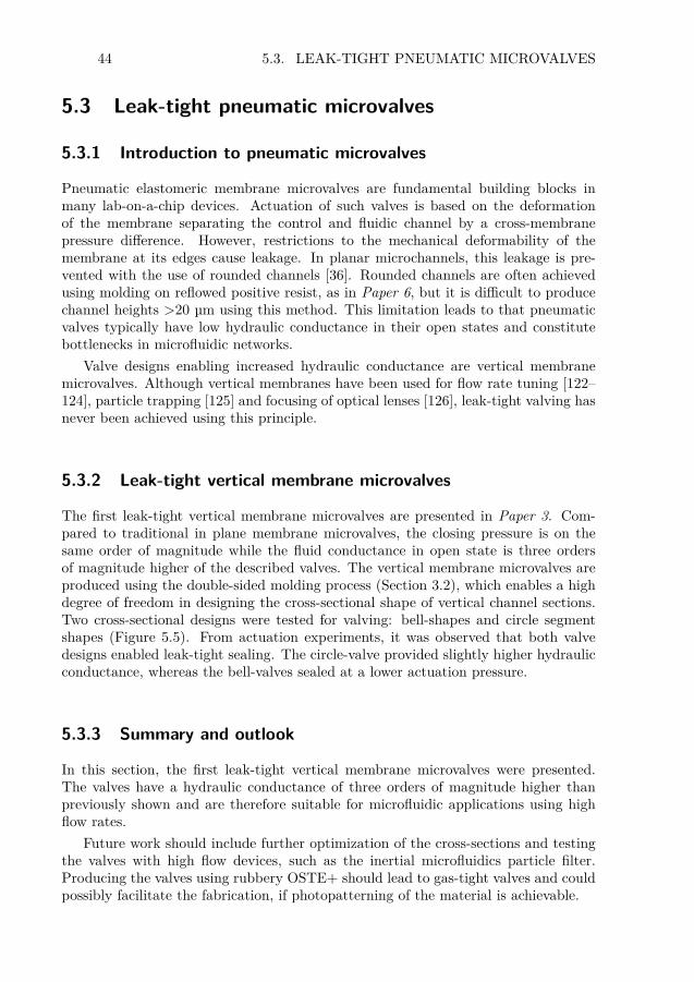
44 5.3. LEAK-TIGHT PNEUMATIC MICROVALVES
5.3 Leak-tight pneumatic microvalves
5.3.1 Introduction to pneumatic microvalves
Pneumatic elastomeric membrane microvalves are fundamental building blocks inmany lab-on-a-chip devices. Actuation of such valves is based on the deformationof the membrane separating the control and fluidic channel by a cross-membranepressure difference. However, restrictions to the mechanical deformability of themembrane at its edges cause leakage. In planar microchannels, this leakage is pre-vented with the use of rounded channels [36]. Rounded channels are often achievedusing molding on reflowed positive resist, as in Paper 6, but it is difficult to producechannel heights >20 µm using this method. This limitation leads to that pneumaticvalves typically have low hydraulic conductance in their open states and constitutebottlenecks in microfluidic networks.
Valve designs enabling increased hydraulic conductance are vertical membranemicrovalves. Although vertical membranes have been used for flow rate tuning [122–124], particle trapping [125] and focusing of optical lenses [126], leak-tight valving hasnever been achieved using this principle.
5.3.2 Leak-tight vertical membrane microvalves
The first leak-tight vertical membrane microvalves are presented in Paper 3. Com-pared to traditional in plane membrane microvalves, the closing pressure is on thesame order of magnitude while the fluid conductance in open state is three ordersof magnitude higher of the described valves. The vertical membrane microvalves areproduced using the double-sided molding process (Section 3.2), which enables a highdegree of freedom in designing the cross-sectional shape of vertical channel sections.Two cross-sectional designs were tested for valving: bell-shapes and circle segmentshapes (Figure 5.5). From actuation experiments, it was observed that both valvedesigns enabled leak-tight sealing. The circle-valve provided slightly higher hydraulicconductance, whereas the bell-valves sealed at a lower actuation pressure.
5.3.3 Summary and outlook
In this section, the first leak-tight vertical membrane microvalves were presented.The valves have a hydraulic conductance of three orders of magnitude higher thanpreviously shown and are therefore suitable for microfluidic applications using highflow rates.
Future work should include further optimization of the cross-sections and testingthe valves with high flow devices, such as the inertial microfluidics particle filter.Producing the valves using rubbery OSTE+ should lead to gas-tight valves and couldpossibly facilitate the fabrication, if photopatterning of the material is achievable.

CHAPTER 5. NOVEL LOC SYSTEMS FOR SEPSIS DIAGNOSTICS 45
Circle-valve
0 kPa 100 kPa 300 kPa
100 µm100 µm
Membrane
Open Closed
Liquid channel
Gas pressure
Vertical micro"uidic
channel for valving
Gas pressure chamber
Membrane for
valving
Liquid "ow
Gas pressure
Bell-valve
0 kPa 100 kPa 300 kPa
Figure 5.5. The principle (top) and performance (bottom) of novel pneumaticallyactuated vertical membrane microvalves.
5.4 Integration of microfluidic components into alab-on-a-chip
5.4.1 Introduction to integrationThe possibility to integrate components into a functional LOC device adds a lot ofvalue to the field by enabling automation, fast analysis and a high level of usability.For sepsis diagnostics, also non-integrated solutions could reduce the delay in antibi-otic susceptibility tests used today. However, integration is needed to reduce analysistime, avoid manual handling, and reduce the risks of cross-contaminations and sampleloss.
Successful LOC integration means that separate components are well integratedand can perform a specific analysis protocol. The layout of the integrated chip willdepend on the protocol sequence, the component structures, and requirements forchip interfacing and fluid control via pumping and valving. Integration requires thatthe components are adapted for connecting to up- and downstream processes, suchas the particle filter and on-chip PCR devices presented in Sections 5.1-5.2, to avoidfurther development of components. The integrated design often requires methodsand components for liquid manipulation by pumping, mixing and valving.
5.4.2 Integration of on-chip PCR with a DNA array for genedetection
The first microfluidic channel network for the integrated LOC device was produced inthe material PDMS. The fluidic design for integration of the PCR and the biosensorsinto one device was based on the following analysis protocol:
1. The DNA sample is loaded into the PCR chamber.
2. The PCR chamber is closed off by valves and PCR is performed.

46 5.4. INTEGRATION OF COMPONENTS INTO A LAB-ON-A-CHIP
3. Valves are opened and a hybridization buffer is introduced and mixed with thePCR product in a 1:3 ratio.
4. The mixture is flushed past the sensor array to let DNA hybridize to the array.Reagents and washing liquids are flushed past the sensor array and detectionis performed in real-time (photonic sensors) or after (colorimetric readout) theexperiment.
The required liquid handling on the microchip according to this protocol led to apreliminary chip layout of the fluidics and lab-on-a-chip components (Figure 5.5).Pressure control for pneumatic valves, the degassing system and liquid pumping isaccomplished using small rotary pumps on the instrument (Figure 2.2). The loadingof the DNA sample into the PCR chamber is achieved by evacuating the air from thePCR chamber using the degassing system. After the PCR, the hybridization buffer isintroduced at a fluidic port and is split in two fractions: a third of the flow presses thePCR product out of the PCR chamber towards the sensor chamber. When the PCRproduct leaves the PCR chamber, it enters a microchannel where it merges with theremaining two thirds of the buffer flow. Mixing of the liquids is achieved by paralleldiffusion while travelling towards the sensor chamber. The mixing ratio 1:3 (PCRproduct:hybridization mixture) was set by tuning of the hydraulic resistances of thetwo paths.
Valving of the channels was done using previously shown pneumatic microvalves[36]. Unfortunately, these valves have two orders of magnitude higher hydraulicresistance than the microchannels, which leads to prolonged analysis time. Also, thevalves strongly influence the balancing of the hydraulic resistances used for tuning ofthe mixing ratios. Such tuning should be done by changing the channel lengths, notcross-sections, to achieve robust balancing, since hydraulic resistance scales linearlywith channel length and to the fourth power with channel cross-section (Section 2.2).
2 mm
Sensor chamber
Valve
PCR sampleinlet
PCR chamber
with degassing
Valve
Valve
Valve
Valve
Low gas pressure
Waste outlet
Bu!er inlet
1
2
3
4
Valve
Light coupling window for photonics
Figure 5.6. The microchip layout used for on-chip PCR and packaging of biosensors.
5.4.3 Packaging of lab-on-a-chip devicesThe microfluidic layers were assembled with the DNA arrays and other materials toform a microchip. Two similar packages were developed, for the photonic sensorchip and the colorimetric DNA array, respectively. The assemblies consists of abottom copper chip holder, a silicon plate for the PCR chamber bottom, a DNA array,

CHAPTER 5. NOVEL LOC SYSTEMS FOR SEPSIS DIAGNOSTICS 47
two PDMS fluidics layers, and a top polycarbonate lid containing a sample loadingwell and interfaces for gas and fluidic connections. The PDMS layers were plasmabonded onto the bottom silicon plate and the DNA array using plasma bonding.The stiff plastic lid was silanized and bonded onto the PDMS using plasma bonding.The assembly was then placed and adhered onto a copper holder with recesses forthe silicon and DNA array, into which the silicon piece was adhered using thermalconductive paste. In the photonic sensor package, the silicon chip was adhered to thecopper recess using thermal conductive paste. In the colorimetric package, a glasspiece with the DNA array was placed into a pre-molded PDMS recess, to which itbonded using plasma activation.
Photonic sensor chip for DNA
detection (not yet integrated)
DNA array on glass for
colorimetric readout
Figure 5.7. Packages for lab-on-a-chip devices with PCR chambers, microvalves,mixers and two variants of DNA arrays: a photonic sensor chip (above) and a glasschip for colorimetric readout (below).
5.4.4 Summary and outlook
In this section, the fabrication process of a LOC device containing a PCR chamber,degassing structures, a sensor chamber and mixing and valving capabilities was de-scribed. Also, the assembly process of the fluidic package into a LOC device wasdescribed. At the time of writing, the integrated chips were not yet tested with PCRand hybridization experiments.
In future work, the vertical membrane valves described in Section 5.3 should beincluded in the integrated package, to improve balancing of hydraulic resistances formixing and reduce the analysis time. Finally, when bacterial extraction is successful,an integrated system for all important process steps (bacteria isolation, cell lysis,

48 5.4. INTEGRATION OF COMPONENTS INTO A LAB-ON-A-CHIP
DNA extraction, DNA purification, PCR and detection) for blood stream infectionanalysis should be developed.
An unsolved challenge is to find an integration solution that meets all requirementsin the list in Section 2.5, since PDMS is required for bubble removal and OSTE forbiocompatible bonding to the DNA array. However, a design using a stiff bottomOSTE+ layer with a printed DNA array, a rubbery OSTE+ layer for valving, a PDMSlayer for degassing, and a stiff lid of OSTE+ containing microchannels and interfaceswould reduce the number of assembly steps and materials required for the device andshould be investigated. The potential to use irradiation for both micropatterningand assembly of OSTE-based microchips could lead to further simplification of thepackaging and manufacturing process.

49
Chapter 6
Conclusions
There is a strong clinical need for rapid detection of antibiotic resistance genes inbacteria found in samples from patients with blood stream infection. Informationabout antibiotic susceptibility will lead to proper de-escalation of the strong ther-apeutics used today, which will improve patient treatment and save lives. In thisthesis, advances in microfabrication and lab-on-a-chip technologies were presented.These advances are crucial steps towards realization of diagnostic devices for bacteriagene detection.
An important step towards rapid sepsis diagnostics is to find alternative solu-tions to detecting antibiotic susceptibility, besides the time-consuming culturing ofpathogens. Microfluidics and lab-on-a-chip technology have the potential to avoidculturing by isolating bacteria already present in the blood and performing analysison these. In this thesis, a system based on inertial microfluidics was presented,which enables high flow particle filtration using parallelization. In a device with16 parallel microchannels connected to the same in- and outlets by 3D microfluidics,95 % filtration efficiency was accomplished at a flow rate of >3 ml/min for filtrationof 10 µm from 2 µm sized particles. The possibility for integrating the system withdownstream processes and to achieve high flow rates by parallelization, are importantsteps towards a bacteria isolation system for detection of blood stream infection.
Another important component for rapid diagnostics is the use of PCR to achieveDNA amplification. A common cause of failure for PCR-on-chip is formation ofbubbles due to outgassing at high temperatures. In this thesis, the first degassingmethod with low water loss that is fast enough to enable bubble-free PCR waspresented. The system utilizes active degassing of PCR-on-chip through a semi-permeable membrane, consisting of a thin layer of PDMS with a thin Teflon AFcoating. Since gas bubbles are problematic for most microfluidic systems, this methodcan enable improved performance of many existing, and future, lab-on-a-chip systems.
To manufacture the particle filter and the degassing system, novel PDMS manufac-turing methods were developed. The parallelization used for the particle filter requireda 3D fluidic network to connect the channels and enable extraction of particles. Thedegassing system required both a thin, fragile membrane and 3D fluidics to function,which was not possible to achieve using previously shown fabrication methods. Thesestructures were enabled by the introduction of the water-dissolvable polymer PVA
50
as a sacrificial carrier for low-strain release, which was modified with amine groupsto enable the formation of through-holes. A fabrication method using a PVA moldcoating and release in a water bath enabled floatation transfer, which is the firstscalable method enabling mild transfer and assembly of thin wafer-sized layers ofPDMS. These methods were combined with a double-sided molding technique toenable the formation of 3D fluidic networks and fragile structures in monolithicstructures of PDMS, thus avoiding difficult manual assembly steps of previously shownmethods. The method enabled the production of the first leak-tight vertical membranemicrovalves, having three orders of magnitude higher hydraulic conductance thantraditional planar valves. The introduced PDMS fabrication methods can facilitatethe manufacturing of complex PDMS structures in both academia and in industrial,up-scaled production.
The novel lab-on-a-chip material platform OSTE was used as a second prototypingmaterial. In this thesis, a mechanism that enables increasing patterning accuracy withincreasing off-stoichiometry in photopatterning of thiol-ene polymers was presented.The mechanism leads to improved photolithography and gradients of cross-linking,available surface groups, refractive index and more. The mechanism was used toenable a method for rapid prototyping of microfluidic chips. Photopatterning inOSTE enabled fast, scalable, and mold-free manufacturing of microfluidic chips,which enabled wetting control in microchannels by a protocol for surface modifi-cation. Also, a novel rubbery OSTE material was presented, which was formed byincluding a flexible epoxy monomer into OSTE and reducing the number of cross-links between monomers. This material is gas-tight, has greatly reduced absorptionof small molecules compared to PDMS and shares the benefits of fast prototyping,easy assembly and surface modifications with the OSTE material platform.
Future work should be focused on developing more sensitive methods and increasedperformance of particle filtering and DNA amplification. Also, integration of devicesfor bacteria isolation and DNA extraction, purification, amplification and sensingshould be performed for the development of a lab-on-a-chip device for sepsis and bloodstream infection diagnostics. The achievements and improvements in microfabricationand lab-on-a-chip technology described in this thesis are important advances towardsimproved diagnostic devices, and will facilitate further research and development ofrapid sepsis and blood stream infection diagnostics.

51
Summary of appended papers
Paper 1: Fabrication and transfer of fragile 3D PDMS microstructuresIn this article, we introduce the water-dissolvable polymer PVA as a material enablingfabrication of fragile structures. The use of PVA as a protective carrier enablesdemolding, transfer and carrier release of thin PDMS membranes. PVA film and aPVA coating agent are evaluated for the production of fragile layers and the compat-ibility with a previously shown method to produce through-holes using aminosilanefor local polymerization inhibition. We found that the PVA film is a fast and reliablemethod for membrane manufacturing, and that the PVA coating enables simultaneousformation of through-holes and thin membranes.
Paper 2: Low-stress transfer bonding using floatationWe introduce the concept of floatation to achieve mild transfer conditions for large,fragile sheets. PVA is used as a coating material, which dissolves during ultrasonica-tion in water a water bath. The PDMS layer floats to the surface of the water bath andis transferred to a destination surface while in the water. Guidance by the containerwalls leads to rough alignment, which can be adjustment manually while the PDMSlayer rests on a water film on the destination surface. The process results in wrinkle-free contacting of large, thin sheets of PDMS. Using this method, we transferred 4inch wafer sized thin PDMS layers to a destination silicon wafer and accomplishedmultilayer stacking with a misalignment ≤40 µm and bonding using silane.
Paper 3: Leak-tight vertical membrane microvalves in PDMS enabled bya novel 3D manufacturing processWe introduce the first leak-tight vertical membrane microvalves, having a hydraulicconductance three orders of magnitude larger than traditional in-plane valves. Thevalves are produced by a fabrication method that enables the formation of monolithicPDMS layers containing fragile structures and microchannels on two sides, connectedby through-holes, in one molding step. Double-sided molding using two micromoldscoated with silanized PVA enables low-stress water release, transfer using floatationand the formation of through holes. Alignment is done using guiding structures priorpolymerization, resulting in a misalignment of ≤25 µm, thus avoiding a low-yieldalignment step in traditional PDMS manufacturing.

52 SUMMARY OF APPENDED PAPERS
Paper 4: Off-stoichiometry improves photopatterning of thiol-enes throughdiffusion-induced monomer depletionHere we introduce the new findings of a mechanism that arise during photopatterningof thiol-ene polymers. Using Raman microscopy, we investigated how the cross-linkingbehavior changed with stoichiometry and found that a depletion process occurring atthe border leads to more accurate patterning with increasing off-stoichiometry.
Paper 5: Rapid mold-free manufacturing of microfluidic devices with ro-bust and spatially directed surface modificationsHere we introduce a method for rapid manufacturing using photolithography directlyon OSTE polymer, complete with protocols for structure development and surfacemodifications. The method enables high-resolution patterning of layers that are as-sembled and form bonds withstanding up to 4 bar of gas pressure. The result is highlytransparent microchips containing both hydrophilic and hydrophobic microchannels.
Paper 6: Low gas permeable and non-absorbent rubbery OSTE+ forpneumatic microvalvesIn this peer-reviewed conference proceedings paper, we introduce a novel materialbased on thiol-ene. A rubbery epoxy component was introduced to form a thiol-enewith flexibility comparable to PDMS. The material was found to have low absorbanceof small molecules and enabled the formation of gas-tight pneumatic valves, thussolving a problem found in PDMS-based valves.
Paper 7: Inertial microfluidics in parallel channels for high-throughputapplicationsHere we present a system enabling upscaling of inertial focusing in parallel channels.The method is based on 3D fluidics and enables filtration and extraction of particlesto an isolated output, which is suitable for integration with downstream processes.We filtered 10 µm from 2 µm particles with a filtration efficiency of 95 % at a flowrate of 3.2 ml/s using systems with 16 parallel channels.
Paper 8: Active liquid degassing in microfluidic systemsIn this paper we introduce the first device to enable efficient bubble removal forheated microfluidic systems. We used active degassing through a semipermeablePDMS/Teflon AF membrane to enable bubble removal while preventing water losses.Compatibility of the degassing system with PCR-on-chip is shown, using a PCRprotocol for amplification of MRSA-specific genes, which was detected on a DNAarray.

53
Acknowledgements
There are many people who have guided and helped me during my years as a PhDstudent in the Micro and Nanosystems group at KTH.
First of all, I wish to thank my main supervisor Wouter, for giving me theopportunity to work with very exciting research in the MST group, and for theimmense work and a seemingly never ending energy to bring me on the right track. Iwant to thank my co-supervisor Tommy, for fantastic coaching, for great discussionsabout all things imaginable, and for figuring out chemical solutions to the mostunexpected things.
I also wish to thank Göran, for forming, preserving and improving the uniquelyinventive environment of MST; Jonas, for excellent collaborations, discussions, coach-ing, for creating great things from not so great things, and for the friendship; FredrikC, for always welcoming me into his office during my drop-in visits, for the friendshipand all the fun time in the lab and in many other places in the world; Staffan, fordown-to-earth chit-chats and visionary discussions, and for the great company andfriendship; Gaspard, for being a good friend and colleague since my first day in thegroup; Umer, for all the fun over the years; Niklas, for a long good friendship and forspreading a nice atmosphere; Aman, for being a “bonus supervisor” and a constantsource of inspiration and ideas; Alexander, for great discussions and collaborations;Omkar, for two summers of fantastic progress.
Many thanks to all of you who have made the MST group a fun place to workat, for being helpful and great sources of inspiration, and for the friendship over theyears: Laila, Hithesh, Henrik G, Fritzi, Gabriel, Kristinn, Reza, Farizah, Fredrik F,Kjell, Andreas, Xiamo, Mikael S, Erika, Mikael A, Niclas, Zargham, Floria, Valentin,Hans, Yitong, Javad, Annika A, Fransisca, Frank, Joachim, Stephan B, Nikolaj, Mina,Simon, Carlos, Stephan S, Ulrika, Martin, Nutapong, Maoxiang, Xuge, Adit, MikaelB.
Thanks to the funding resources, especially the FP-7 funded EU project Intopsensand the IMI funded Rapp-ID, in which much of the work was performed. Many thanksto my colleagues in the Intopsens and Rapp-ID consortia, especially Muriel, Sanna,Akseli, Minna, Hermann, and Gerry for excellent collaborations and for providinggreat work environments during my visits.
All my friends in other schools at KTH, especially Sahar, Harisha, Prem, Per,Staffan, Emilie, and Håkan, for all the fun in the labs, during conference trips, climatediscussions and other out-of-office activities.

54 ACKNOWLEDGEMENTS
Mina kollegor på Clinical Innovation Fellowships och CTMH som visade vadvärlden utanför akademin har att erbjuda. Alla mina vänner från Linköping, Stock-holm och Oskarshamn, i synnerhet Anders, som varit en oerhört viktig stöttning påplats, och Patrik M, som vid det här laget kan lika mycket om mikrofluidik som jag.Mina släktingar och min familj, som stött mig genom processen och som jag träffatalldeles för sällan under doktorandtiden. Slutligen: den allra viktigaste personenbakom den här boken är du, Helen. Inget hade varit möjligt utan din förståelse,stöttning och kärlek.
Supportive PDMS pillars keeping a water droplet together and preventing its collapseonto a floor of glass.

55
References
[1] Konrad Reinhart, Ron Daniels, Niranjan Kissoon, James O’Brien, Flavia R. Machado,and Edgar Jimenez. The burden of sepsis a call to action in support of world sepsisday 2013. Journal of Critical Care, 28(4):526–528, August 2013.
[2] N. Mancini, S. Carletti, N. Ghidoli, P. Cichero, R. Burioni, and M. Clementi. Theera of molecular and other non-culture-based methods in diagnosis of sepsis. ClinicalMicrobiology Reviews, 23(1):235–251, January 2010.
[3] World Health Organization. Antimicrobial resistance: global report on surveillance,2014. 2014.
[4] R. P. Elander. Industrial production of beta-lactam antibiotics. Applied Microbiologyand Biotechnology, 61(5-6):385–392, June 2003.
[5] EARSS. Antimicrobial resistance surveillance in europe 2012. Technical report, 2012.[6] Spiros Miyakis, Angelos Pefanis, and Athanassios Tsakris. The challenges of
antimicrobial drug resistance in greece. Clinical Infectious Diseases, 53(2):177–184,July 2011.
[7] Anand Kumar, Daniel Roberts, Kenneth E. Wood, Bruce Light, Joseph E. Parrillo,Satendra Sharma, Robert Suppes, Daniel Feinstein, Sergio Zanotti, Leo Taiberg, DavidGurka, Aseem Kumar, and Mary Cheang. Duration of hypotension before initiation ofeffective antimicrobial therapy is the critical determinant of survival in human septicshock. Critical Care Medicine, 34(6):1589–1596, June 2006.
[8] Arash Afshari, Jacques Schrenzel, Margareta Ieven, and Stephan Harbarth. Bench-to-bedside review: Rapid molecular diagnostics for bloodstream infection - a new frontier?Critical Care, 16(3):222, May 2012.
[9] J. Garnacho-Montero, A. Gutierrez-Pizarraya, A. Escoresca-Ortega, Y. Corcia-Palomo,Esperanza Fernandez-Delgado, I. Herrera-Melero, C. Ortiz-Leyba, and J. A. Marquez-Vacaro. De-escalation of empirical therapy is associated with lower mortality inpatients with severe sepsis and septic shock. Intensive Care Medicine, 40(1):32–40,January 2014.
[10] James A. Russell. Management of sepsis. New England Journal of Medicine,355(16):1699–1713, 2006.
[11] C C Butler, K Hood, T Verheij, P Little, H Melbye, J Nuttall, M J Kelly, S Molstad,M Godycki-Cwirko, J Almirall, A Torres, D Gillespie, U Rautakorpi, S Coenen, andH Goossens. Variation in antibiotic prescribing and its impact on recovery in patientswith acute cough in primary care: prospective study in 13 countries. BMJ, 338(jun232):b2242–b2242, June 2009.
[12] Frank M. White. Fluid Mechanics. McGraw-Hill, New York, NY, 7th edition edition,2011.

56 REFERENCES
[13] P. Gravesen, J. Branebjerg, and O. S. Jensen. Microfluidics-a review. Journal ofMicromechanics and Microengineering, 3(4):168, December 1993.
[14] Nam-Trung Nguyen and Zhigang Wu. Micromixers - a review. Journal ofMicromechanics and Microengineering, 15(2):R1, February 2005.
[15] Henrik Bruus. Theoretical microfluidics. Oxford University Press„ Oxford ;, 2008.[16] A. Kloke, A. R. Fiebach, S. Zhang, L. Drechsel, S. Niekrawietz, M. M. Hoehl,
R. Kneusel, K. Panthel, J. Steigert, F. von Stetten, R. Zengerle, and N. Paust.The LabTube âĂŞ a novel microfluidic platform for assay automation in laboratorycentrifuges. Lab on a Chip, 14(9):1527–1537, April 2014.
[17] H. M. Ji, V. Samper, Y. Chen, W. C. Hui, H. J. Lye, F. B. Mustafa, A. C. Lee, L. Cong,C. K. Heng, and T. M. Lim. DNA purification silicon chip. Sensors and Actuators A,139:139–144, 2007.
[18] F. K. Balagadde and Stephen Quake. Long-term monitoring of bacteria undergoingprogrammed population control in a microchemostat. Science, 309(5731):137–140, July2005.
[19] Bruce Alberts, Alexander Johnson, Julian Lewis, Martin Raff, Keith Roberts, andPeter Walter. Molecular Biology of the Cell. Garland Science, 4th edition, 2002.
[20] Palaniappan Sethu, Aaron Sin, and Mehmet Toner. Microfluidic diffusive filter forapheresis (leukapheresis). Lab on a Chip, 6(1):83, 2006.
[21] W. A. Al-Soud and P. Radstrom. Purification and characterization of PCR-inhibitorycomponents in blood cells. Journal of Clinical Microbiology, 39(2):485–493, February2001.
[22] Andreas Nilsson, Filip Petersson, Henrik Jonsson, and Thomas Laurell. Acousticcontrol of suspended particles in micro fluidic chips. Lab on a Chip, 4(2):131, 2004.
[23] Seungkyung Park, Yi Zhang, Tza-Huei Wang, and Samuel Yang. Continuousdielectrophoretic bacterial separation and concentration from physiological media ofhigh conductivity. Lab on a Chip, 11(17):2893–2900, August 2011.
[24] A. Ashkin, J. M. Dziedzic, and T. Yamane. Optical trapping and manipulation ofsingle cells using infrared laser beams. Nature, 330(6150):769–771, December 1987.
[25] Ciprian Iliescu, Guolin Xu, Elena Barbarini, Marioara Avram, and Andrei Avram.Microfluidic device for continuous magnetophoretic separation of white blood cells.Microsystem Technologies, 15(8):1157–1162, August 2009.
[26] Nicole Pamme. Continuous flow separations in microfluidic devices. Lab on a Chip,7(12):1644, 2007.
[27] John Davis, David Inglis, Keith Morton, David Lawrence, Lotien Huang, StephenChou, James Sturm, and Robert Austin. Deterministic hydrodynamics: Taking bloodapart. Proceedings of the National Academy of Sciences, 103(40):14779–14784, October2006.
[28] Junya Takagi, Masumi Yamada, Masahiro Yasuda, and Minoru Seki. Continuousparticle separation in a microchannel having asymmetrically arranged multiplebranches. Lab on a Chip, 5(7):778, 2005.
[29] Xing Chen, Da Fu Cui, and Chang Chun Liu. On-line cell lysis and DNA extractionon a microfluidic biochip fabricated by microelectromechanical system technology.ELECTROPHORESIS, 29(9):1844–1851, May 2008.

REFERENCES 57
[30] Seungkyung Park, Yi Zhang, Shin Lin, Tza-Huei Wang, and Samuel Yang. Advancesin microfluidic PCR for point-of-care infectious disease diagnostics. BiotechnologyAdvances, 29(6):830–839, November 2011.
[31] Hao-Bing Liu, Hai-Qing Gong, Naveen Ramalingam, Yu Jiang, Chang-Chun Dai,and Kam M Hui. Micro air bubble formation and its control during polymerasechain reaction (PCR) in polydimethylsiloxane (PDMS) microreactors. Journal ofMicromechanics and Microengineering, 17(10):2055–2064, October 2007.
[32] V. Toccafondo, J. Garcia-Ruperez, M. J. Banuls, A. Griol, J. G. Castello, S. Peransi-Llopis, and A. Maquieira. Single-strand DNA detection using a planar photonic-crystal-waveguide-based sensor. Optics Letters, 35(21):3673–3675, November 2010.
[33] Tom Claes, Wim Bogaerts, and Peter Bienstman. Experimental characterization ofa silicon photonic biosensor consisting of two cascaded ring resonators based on thevernier-effect and introduction of a curve fitting method for an improved detectionlimit. Optics Express, 18(22):22747–22761, 2010.
[34] David C. Duffy, J. Cooper McDonald, Olivier J. A. Schueller, and George M.Whitesides. Rapid prototyping of microfluidic systems in poly(dimethylsiloxane).Analytical Chemistry, 70(23):4974–4984, December 1998.
[35] George M. Whitesides. The origins and the future of microfluidics. Nature,442(7101):368–373, July 2006.
[36] Marc A. Unger, Hou-Pu Chou, Todd Thorsen, Axel Scherer, and Stephen R. Quake.Monolithic microfabricated valves and pumps by multilayer soft lithography. Science,288(5463):113–116, April 2000.
[37] Rajendrani Mukhopadhyay. When PDMS isn’t the best. Analytical chemistry,79(9):3248–3253, 2007.
[38] Philip T. Shemella, Teodoro Laino, Oliver Fritz, and Alessandro Curioni.Understanding the self-healing hydrophobic recovery of high-voltage insulators. TheJournal of Physical Chemistry B, 116(24):7351–7356, June 2012.
[39] Janelle R. Anderson, Daniel T. Chiu, Rebecca J. Jackman, Oksana Cherniavskaya,J. Cooper McDonald, Hongkai Wu, Sue H. Whitesides, and George M. Whitesides.Fabrication of topologically complex three-dimensional microfluidic systems in PDMSby rapid prototyping. Analytical Chemistry, 72(14):3158–3164, July 2000.
[40] B.-H. Jo, L.M. Van Lerberghe, K.M. Motsegood, and D.J. Beebe. Three-dimensionalmicro-channel fabrication in polydimethylsiloxane (PDMS) elastomer. Journal ofMicroelectromechanical Systems, 9(1):76–81, 2000. Cited by 0847.
[41] William R. Childs and Ralph G. Nuzzo. Decal transfer microlithographyâĂĽ anew soft-lithographic patterning method. Journal of the American Chemical Society,124(45):13583–13596, November 2002.
[42] Hongkai Wu, Teri W. Odom, Daniel T. Chiu, and George M. Whitesides. Fabricationof complex three-dimensional microchannel systems in PDMS. Journal of the AmericanChemical Society, 125(2):554–559, January 2003. Cited by 0220.
[43] Matthew A. Meitl, Zheng-Tao Zhu, Vipan Kumar, Keon Jae Lee, Xue Feng,Yonggang Y. Huang, Ilesanmi Adesida, Ralph G. Nuzzo, and John A. Rogers. Transferprinting by kinetic control of adhesion to an elastomeric stamp. Nature Materials,5(1):33–38, January 2006.
[44] Yiqi Luo and Richard N. Zare. Perforated membrane method for fabricating three-dimensional polydimethylsiloxane microfluidic devices. Lab on a Chip, 8(10):1688,2008.
58 REFERENCES
[45] Kwang-Seok Yun and Euisik Yoon. Fabrication of complex multilevel microchannels inPDMS by using three-dimensional photoresist masters. Lab on a Chip, 8(2):245–250,January 2008.
[46] Joo H. Kang, Eujin Um, and Je-Kyun Park. Fabrication of a poly(dimethylsiloxane)membrane with well-defined through-holes for three-dimensional microfluidic networks.Journal of Micromechanics and Microengineering, 19(4):045027, April 2009.
[47] Alvaro Mata, Eun Jung Kim, Cynthia A. Boehm, Aaron J. Fleischman, George F.Muschler, and Shuvo Roy. A three-dimensional scaffold with precise micro-architectureand surface micro-textures. Biomaterials, 30(27):4610–4617, September 2009.
[48] Christopher Moraes, Yu Sun, and Craig A. Simmons. Solving the shrinkage-induced PDMS alignment registration issue in multilayer soft lithography. Journalof Micromechanics and Microengineering, 19(6):065015, June 2009.
[49] C.F. Carlborg, T. Haraldsson, M. Cornaglia, G. Stemme, and W. van der Wijngaart.A high-yield process for 3-d large-scale integrated microfluidic networks in PDMS.Journal of Microelectromechanical Systems, 19(5):1050–1057, 2010.
[50] Bobak Mosadegh, Mayank Agarwal, Yu-suke Torisawa, and Shuichi Takayama.Simultaneous fabrication of PDMS through-holes for three-dimensional microfluidicapplications. Lab on a Chip, 10(15):1983–1986, August 2010.
[51] Mengying Zhang, Jinbo Wu, Limu Wang, Kang Xiao, and Weijia Wen. A simplemethod for fabricating multi-layer PDMS structures for 3d microfluidic chips. Lab ona Chip, 10(9):1199–1203, May 2010.
[52] Shifeng Li and Shaochen Chen. Polydimethylsioxane fluidic interconnects formicrofluidic systems. IEEE Transactions on Advanced Packaging, 26(3):242–247, 2003.Cited by 0066.
[53] J.Y. Kim, J.Y. Baek, K.A. Lee, and S.H. Lee. Automatic aligning and bonding systemof PDMS layer for the fabrication of 3d microfluidic channels. Sensors and ActuatorsA: Physical, 119(2):593–598, April 2005.
[54] N Lucas, S Demming, A Jordan, P Sichler, and S BÃijttgenbach. An improved methodfor double-sided moulding of PDMS. Journal of Micromechanics and Microengineering,18(7):075037, August 2008.
[55] Kei Toda, Shin-Ichi Ohira, and Misuzu Ikeda. Micro-gas analysis system comprising amicrochannel scrubber and a micro-fluorescence detector for measurement of hydrogensulfide. Analytica Chimica Acta, 511(1):3–10, 2004.
[56] Mark A. Eddings and Bruce K. Gale. A PDMS-based gas permeation pumpfor on-chip fluid handling in microfluidic devices. Journal of Micromechanics andMicroengineering, 16(11):2396, November 2006.
[57] N Stafie, D. F Stamatialis, and M Wessling. Insight into the transport of hexane solutesystems through tailor-made composite membranes. Journal of Membrane Science,228(1):103–116, January 2004.
[58] Abel L. Thangawng, Rodney S. Ruoff, Melody A. Swartz, and Matthew R. Glucksberg.An ultra-thin PDMS membrane as a bio/micro nano interface: fabrication andcharacterization. Biomedical Microdevices, 9(4):587–595, July 2007.
[59] K. Kendall. Thin-film peeling-the elastic term. Journal of Physics D: Applied Physics,8(13):1449, 1975.
[60] M J Madou. Fundamentals of Microfabrication, volume 2002. Boca Raton, 2nd ednedition, 2002.
REFERENCES 59
[61] Gaio Paradossi, Francesca Cavalieri, Ester Chiessi, Chiara Spagnoli, and Mary K.Cowman. Poly(vinyl alcohol) as versatile biomaterial for potential biomedicalapplications. Journal of Materials Science: Materials in Medicine, 14(8):687–691,August 2003.
[62] F. L. Marten. Vinyl alcohol polymers. In Encyclopedia of Polymer Science andTechnology. John Wiley & Sons, Inc., 2002.
[63] Hartmuth C. Kolb, M. G. Finn, and K. Barry Sharpless. Click chemistry: Diversechemical function from a few good reactions. Angewandte Chemie InternationalEdition, 40(11):2004–2021, June 2001.
[64] Carl Fredrik Carlborg, Tommy Haraldsson, Kim Oberg, Michael Malkoch, and Woutervan der Wijngaart. Beyond PDMS: off-stoichiometry thiolâĂŞene (OSTE) based softlithography for rapid prototyping of microfluidic devices. Lab on a Chip, 11(18):3136–3147, September 2011.
[65] Fredrik Carlborg, Francesca Moraga, Farizah Saharil, Wouter van der Wijngaart, andTommy Haraldsson. Rapid permanent hydrophilic and hydrophobic patterning ofpolymer surfaces via off-stoichiometry thiol-ene (OSTE) photografting. In ProceedingsMicro Total Analysis Systems (muTAS) 2012, pages 677–679, 2012.
[66] Carl F. Carlborg, Marina Cretich, Tommy Haraldsson, Laura Sola, M. Bagnati,Marcella Chiari, and Wouter van der Wijngaart. Biosticker: patterned microfluidicstickers for rapid integration with microarrays. In 15th International Conference onMiniaturized Systems for Chemistry and Life Sciences (MicroTAS), pages 311–313,2011.
[67] Tommy Haraldsson, Carl Fredrik Carlborg, and Wouter van der Wijngaart. OSTE: anovel polymer system developed for lab-on-chip. volume 8976, pages 897608–897608–6,2014.
[68] Farizah Saharil, Fredrik Forsberg, Yitong Liu, Paolo Bettotti, Neeraj Kumar, FrankNiklaus, Tommy Haraldsson, Wouter van der Wijngaart, and Kristinn B. Gylfason.Dry adhesive bonding of nanoporous inorganic membranes to microfluidic devices usingthe OSTE(+) dual-cure polymer. Journal of Micromechanics and Microengineering,23(2):025021, February 2013.
[69] Carl Fredrik Carlborg, Alexander Vastesson, Yitong Liu, Wouter van der Wijngaart,Mats Johansson, and Tommy Haraldsson. Functional off-stoichiometry thiol-ene-epoxythermosets featuring temporally controlled curing stages via an UV/UV dual cureprocess. Journal of Polymer Science Part A: Polymer Chemistry, pages n/a–n/a,June 2014.
[70] Yitong Liu. High Tg Polymeric Materials for Heated Microfluidic Systems. PhD thesis,2011.
[71] Xiamo Zhou, C. F. Calborg, N. Sandstrom, A. Haleem, A. Vastesson, F. Saharil,W. van der Wijngaart, and T. Haraldsson. Rapid fabrication of OSTE+microfluidic devices with lithographically defined hydrophobic/hydrophilic patternsand biocompatible chip sealing. MicroTAS’13, pages 27–31, 2013.
[72] A. Vastesson, X. Zhou, N. Sandstrom, F. Saharil, O. Supekar, G. Stemme,W. van der Wijngaart, and T. Haraldsson. Robust microdevice manufacturingby direct lithography and adhesive-free bonding of off-stoichiometry thiol-ene-epoxy(OSTE+) polymer. In 2013 Transducers Eurosensors XXVII: The 17th InternationalConference on Solid-State Sensors, Actuators and Microsystems (TRANSDUCERSEUROSENSORS XXVII), pages 408–411, June 2013.

60 REFERENCES
[73] John F. Ashley, Neil B. Cramer, Robert H. Davis, and Christopher N. Bowman. Soft-lithography fabrication of microfluidic features using thiol-ene formulations. Lab on aChip, 11(16):2772–2778, August 2011.
[74] A. del Campo and C. Greiner. SU-8: a photoresist for high-aspect-ratio and 3dsubmicron lithography. Journal of Micromechanics and Microengineering, 17(6):R81,June 2007.
[75] Ansgar Waldbaur, Holger Rapp, Kerstin Lange, and Bastian E. Rapp. Let there be chiptowards rapid prototyping of microfluidic devices: one-step manufacturing processes.Analytical Methods, 3(12):2681–2716, December 2011.
[76] Jessamine Ng Lee, Cheolmin Park, and George M. Whitesides. Solvent compatibility ofpoly(dimethylsiloxane)-based microfluidic devices. Analytical Chemistry, 75(23):6544–6554, December 2003.
[77] Jason P. Rolland, R. Michael Van Dam, Derek A. Schorzman, Stephen R. Quake, andJoseph M. DeSimone. Solvent-resistant photocurable liquid teflon for microfluidicdevice fabrication. Journal of the American Chemical Society, 126(8):2322–2323,March 2004.
[78] G. Sharma, L. Klintberg, and K. Hjort. Viton-based fluoroelastomer microfluidics.Journal of Micromechanics and Microengineering, 21(2):025016, February 2011.
[79] F. Ejserholm, A. Vastesson, T. Haraldsson, W. van der Wijngaart, J. Schouenborg,L. Wallman, and M. Bengtsson. A polymer neural probe with tunable flexibility. In2013 6th International IEEE/EMBS Conference on Neural Engineering (NER), pages691–694, November 2013.
[80] Evgeny S. Asmolov. The inertial lift on a spherical particle in a plane poiseuille flowat large channel reynolds number. Journal of Fluid Mechanics, 381:63–87, 1999.
[81] J. P. Matas, J. F. Morris, and Elisabeth Guazzelli. Lateral forces on a sphere. Oil &gas science and technology, 59(1):59–70, 2004.
[82] Lanying Zeng, S. Balachandar, and Paul Fischer. Wall-induced forces on a rigid sphereat finite reynolds number. Journal of Fluid Mechanics, 536:1–25, July 2005.
[83] Samir Yahiaoui and Francois Feuillebois. Lift on a sphere moving near a wall in aparabolic flow. Journal of Fluid Mechanics, 662:447–474, November 2010.
[84] Dino Di Carlo, Daniel Irimia, Ronald G. Tompkins, and Mehmet Toner. Continuousinertial focusing, ordering, and separation of particles in microchannels. Proceedingsof the National Academy of Sciences, 104(48):18892–18897, 2007.
[85] G. Segre and A. Silberberg. Radial particle displacements in poiseuille flow ofsuspensions. Nature, 189(4760):209–210, January 1961.
[86] Dino Di Carlo. Inertial microfluidics. Lab on a Chip, 9(21):3038–3046, November 2009.[87] Jian Zhou and Ian Papautsky. Fundamentals of inertial focusing in microchannels. Lab
on a Chip, 13(6):1121–1132, February 2013.[88] Ali Asgar S. Bhagat, Sathyakumar S. Kuntaegowdanahalli, and Ian Papautsky.
Enhanced particle filtration in straight microchannels using shear-modulated inertialmigration. Physics of Fluids (1994-present), 20(10):101702, October 2008.
[89] Daniel R. Gossett, Henry Tat Kwong Tse, Jaideep S. Dudani, Keisuke Goda, Travis A.Woods, Steven W. Graves, and Dino Di Carlo. Inertial manipulation and transfer ofmicroparticles across laminar fluid streams. Small, 8(17):2757–2764, September 2012.

REFERENCES 61
[90] Christopher Prohm, Fredi Troltzsch, and Holger Stark. Optimal control of particleseparation in inertial microfluidics. The European Physical Journal E, 36(10):1–13,October 2013.
[91] Katherine J. Humphry, Pandurang M. Kulkarni, David A. Weitz, Jeffrey F. Morris,and Howard A. Stone. Axial and lateral particle ordering in finite reynolds numberchannel flows. Physics of Fluids (1994-present), 22(8):081703, August 2010.
[92] Eugene J. Lim, Thomas J. Ober, Jon F. Edd, Gareth H. McKinley, and Mehmet Toner.Visualization of microscale particle focusing in diluted and whole blood using particletrajectory analysis. Lab on a Chip, 12(12):2199–2210, May 2012.
[93] Zhigang Wu, Ben Willing, Joakim Bjerketorp, Janet K. Jansson, and Klas Hjort. Softinertial microfluidics for high throughput separation of bacteria from human bloodcells. Lab on a Chip, 9(9):1193–1199, May 2009.
[94] Albert J. Mach and Dino Di Carlo. Continuous scalable blood filtration device usinginertial microfluidics. Biotechnology and Bioengineering, 107(2):302–311, 2010.
[95] Nivedita Nivedita and Ian Papautsky. Continuous separation of blood cells in spiralmicrofluidic devices. Biomicrofluidics, 7(5):054101, September 2013.
[96] Aman Russom, Amit K. Gupta, Sunitha Nagrath, Dino Di Carlo, Jon F. Edd, andMehmet Toner. Differential inertial focusing of particles in curved low-aspect-ratiomicrochannels. New Journal of Physics, 11(7):075025, July 2009.
[97] LB Leverett, JD Hellums, CP Alfrey, and EC Lynch. Red blood cell damage by shearstress. Biophys. J., 12(3):257–273, March 1972.
[98] Jian Zhou, Premkumar Vummidi Giridhar, Susan Kasper, and Ian Papautsky.Modulation of aspect ratio for complete separation in an inertial microfluidic channel.Lab on a Chip, 13(10):1919–1929, April 2013.
[99] Mahdokht Masaeli, Elodie Sollier, Hamed Amini, Wenbin Mao, Kathryn Camacho,Nishit Doshi, Samir Mitragotri, Alexander Alexeev, and Dino Di Carlo. Continuousinertial focusing and separation of particles by shape. Physical Review X, 2(3):031017,September 2012.
[100] Dino Di Carlo, Jon F. Edd, Daniel Irimia, Ronald G. Tompkins, and Mehmet Toner.Equilibrium separation and filtration of particles using differential inertial focusing.Analytical Chemistry, 80(6):2204–2211, March 2008.
[101] T. Strachan. Human molecular genetics 3. Garland Press, London ; New York, 3rd ededition, 2004.
[102] Chunsun Zhang, Jinliang Xu, Wenli Ma, and Wenling Zheng. PCR microfluidic devicesfor DNA amplification. Biotechnology Advances, 24(3):243–284, May 2006.
[103] Zhen Yang, Sohei Matsumoto, and Ryutaro Maeda. A prototype of ultrasonic micro-degassing device for portable dialysis system. Sensors and Actuators A: Physical,95(2-3):274–280, January 2002.
[104] Dennis Desheng Meng, Joonwon Kim, and Chang-Jin Kim. A degassing plate withhydrophobic bubble capture and distributed venting for microfluidic devices. Journalof Micromechanics and Microengineering, 16(2):419, February 2006.
[105] A. Ranjit Prakash, S. Adamia, V. Sieben, P. Pilarski, L.M. Pilarski, and C.J.Backhouse. Small volume PCR in PDMS biochips with integrated fluid control andvapour barrier. Sensors and Actuators B: Chemical, 113(1):398–409, January 2006.

62 REFERENCES
[106] Tsuyoshi Nakayama, Yasunori Kurosawa, Satoshi Furui, Kagan Kerman, MasaakiKobayashi, S. Ramachandra Rao, Yuji Yonezawa, Kouichi Nakano, Akihiro Hino,Shohei Yamamura, Yuzuru Takamura, and Eiichi Tamiya. Circumventing air bubblesin microfluidic systems and quantitative continuous-flow PCR applications. Analyticaland Bioanalytical Chemistry, 386(5):1327–1333, August 2006.
[107] Scott Matteucci, Yuri Yampolskii, Benny D. Freeman, and Ingo Pinnau. Transport ofgases and vapors in glassy and rubbery polymers. Materials science of membranes forgas and vapor separation, pages 1–47, 2006.
[108] Lloyd M. Robeson. Correlation of separation factor versus permeability for polymericmembranes. Journal of Membrane Science, 62(2):165–185, October 1991.
[109] Lloyd M. Robeson. The upper bound revisited. Journal of Membrane Science,320(1âĂŞ2):390–400, July 2008.
[110] R. L. Taylor, D. B. Herbmann, and A. R. Kemp. Diffusion of water through insulatingmaterials rubber,synthetic resins,and other organics. Industrial & EngineeringChemistry, 28(11):1255–1263, November 1936.
[111] J.A Barrie and B Platt. The diffusion and clustering of water vapour in polymers.Polymer, 4:303–313, 1963.
[112] Geoffrey S. Park. Transport principles solution, diffusion and permeation in polymermembranes. In P. M. Bungay, H. K. Lonsdale, and M. N. de Pinho, editors, SyntheticMembranes: Science, Engineering and Applications, number 181 in NATO ASI Series,pages 57–107. Springer Netherlands, January 1986.
[113] I. Blume, P.J.F. Schwering, M.H.V. Mulder, and C.A. Smolders. Vapour sorption andpermeation properties of poly (dimethylsiloxane) films. Journal of Membrane Science,61:85–97, 1991.
[114] E. Favre, P. Schaetzel, Q.T. Nguygen, R. Clement, and J. Neel. Sorption, diffusionand vapor permeation of various penetrants through dense poly(dimethylsiloxane)membranes: a transport analysis. Journal of Membrane Science, 92(2):169–184, July1994.
[115] J.M. Watson and M.G. Baron. The behaviour of water in poly(dimethylsiloxane).Journal of Membrane Science, 110(1):47–57, February 1996.
[116] Ahmed E. Ismail, Gary S. Grest, David R. Heine, Mark J. Stevens, and Mesfin Tsige.Interfacial structure and dynamics of siloxane systems: PDMS vapor and PDMS water.Macromolecules, 42(8):3186–3194, April 2009.
[117] Stephen J. Harley, Elizabeth A. Glascoe, and Robert S. Maxwell. Thermodynamicstudy on dynamic water vapor sorption in sylgard-184. The Journal of PhysicalChemistry B, 116(48):14183–14190, December 2012.
[118] Cheryl W. Jones and William J. Koros. Carbon composite membranes: A solution toadverse humidity effects. Industrial & Engineering Chemistry Research, 34(1):164–167,January 1995.
[119] T. C. Merkel and L. G. Toy. Comparison of hydrogen sulfide transport properties influorinated and nonfluorinated polymers. Macromolecules, 39(22):7591–7600, October2006.
[120] A Polyakov. Amorphous teflons AF as organophilic pervaporation materials transportof individual components. Journal of Membrane Science, 216(1-2):241–256, May 2003.

REFERENCES 63
[121] Stuart M. Nemser and Ian C. Roman. Perfluorodioxole membranes, September1991. International Classification: B01D71/44; C08F34/02; C08F34/00; B01D71/00;C08F234/02; C08F234/00; C08F214/00; C08F214/26 U.S. Classification: B01D71/44;B01D71/32; B01D53/22M.
[122] A. R. Abate and D. A. Weitz. Single-layer membrane valves for elastomeric microfluidicdevices. Applied Physics Letters, 92(24):243509, 2008.
[123] Adam R. Abate, Mark B. Romanowsky, Jeremy J. Agresti, and David A. Weitz. Valve-based flow focusing for drop formation. Applied Physics Letters, 94(2):023503, 2009.
[124] Il Doh and Young-Ho Cho. Passive flow-rate regulators using pressure-dependentautonomous deflection of parallel membrane valves. Lab on a Chip, 9(14):2070, 2009.
[125] Hojin Kim, Sangmin Lee, and Joonwon Kim. Hydrodynamic trap-and-release ofsingle particles using dual-function elastomeric valves: design, fabrication, andcharacterization. Microfluidics and Nanofluidics, 13(5):835–844, November 2012.
[126] Guocheng Shao, Ziliang Cai, Zhengyu Miao, and Wanjun Wang. In-situ fabrication ofan out-of-plane microlens with pre-definable focal length. Microsystem Technologies,19(11):1823–1828, November 2013.
[127] Tobias Metz, Wolfgang Streule, Roland Zengerle, and Peter Koltay. StarTube a tubewith reduced contact line for minimized gas bubble resistance. Langmuir, 24(17):9204–9206, September 2008.
[128] Charles E. Hoyle and Christopher N. Bowman. Thiol ene click chemistry. AngewandteChemie International Edition, 49(9):1540–1573, 2010.
[129] L. H. Thompson and L. K. Doraiswamy. SonochemistryâĂĽ science and engineering.Industrial & Engineering Chemistry Research, 38(4):1215–1249, April 1999.

64 REFERENCES

65
Paper reprints