POLYMER ELECTROLYTE THROUGH ENZYME ... ELECTROLYTE THROUGH ENZYME CATALYSIS FOR HIGH PERFORMANCE...
31
POLYMER ELECTROLYTE THROUGH ENZYME CATALYSIS FOR HIGH PERFORMANCE LITHIUM-ION BATTERIES M. Aldissi Fractal Systems, Inc. 14200 Carlson Circle Tampa, FL 33626 Tel: (813) 854-4332 October 16, 1998 Final Report, A002 Contract No. DAAN02-98-P-8454 April 16 - October 16, 1998 Sponsored by: U.S. Army Soldier Systems Command Code W13G07 Natick, MA 01760-5011 DTIC QrUALITY INSPECTED 4
Transcript of POLYMER ELECTROLYTE THROUGH ENZYME ... ELECTROLYTE THROUGH ENZYME CATALYSIS FOR HIGH PERFORMANCE...

POLYMER ELECTROLYTE THROUGH ENZYME CATALYSIS FOR
HIGH PERFORMANCE LITHIUM-ION BATTERIES
M. AldissiFractal Systems, Inc.14200 Carlson Circle
Tampa, FL 33626Tel: (813) 854-4332
October 16, 1998
Final Report, A002
Contract No. DAAN02-98-P-8454April 16 - October 16, 1998
Sponsored by:
U.S. Army Soldier Systems CommandCode W13G07
Natick, MA 01760-5011
DTIC QrUALITY INSPECTED 4

POLYMER ELECTROLYTE THROUGH ENZYME CATALYSIS FOR
HIGH PERFORMANCE LITHIUM-ION BATTERIES
M. Aldissi and A. BogomolovaFractal Systems, Inc.14200 Carlson Circle
Tampa, FL 33626Tel: (813) 854-4332
October 16, 1998
Final Report, A002Contract No. DAAN02-98-P-8454
April 16 - October 16, 1998
Sponsored by:
U.S. Army Soldier Systems CommandCode W13G07
Natick, MA 01760-5011
5E:Uv.Y ..LA=IFtr6,TION OF THIS PAGE,, i,..,,, • | orm Approvedl
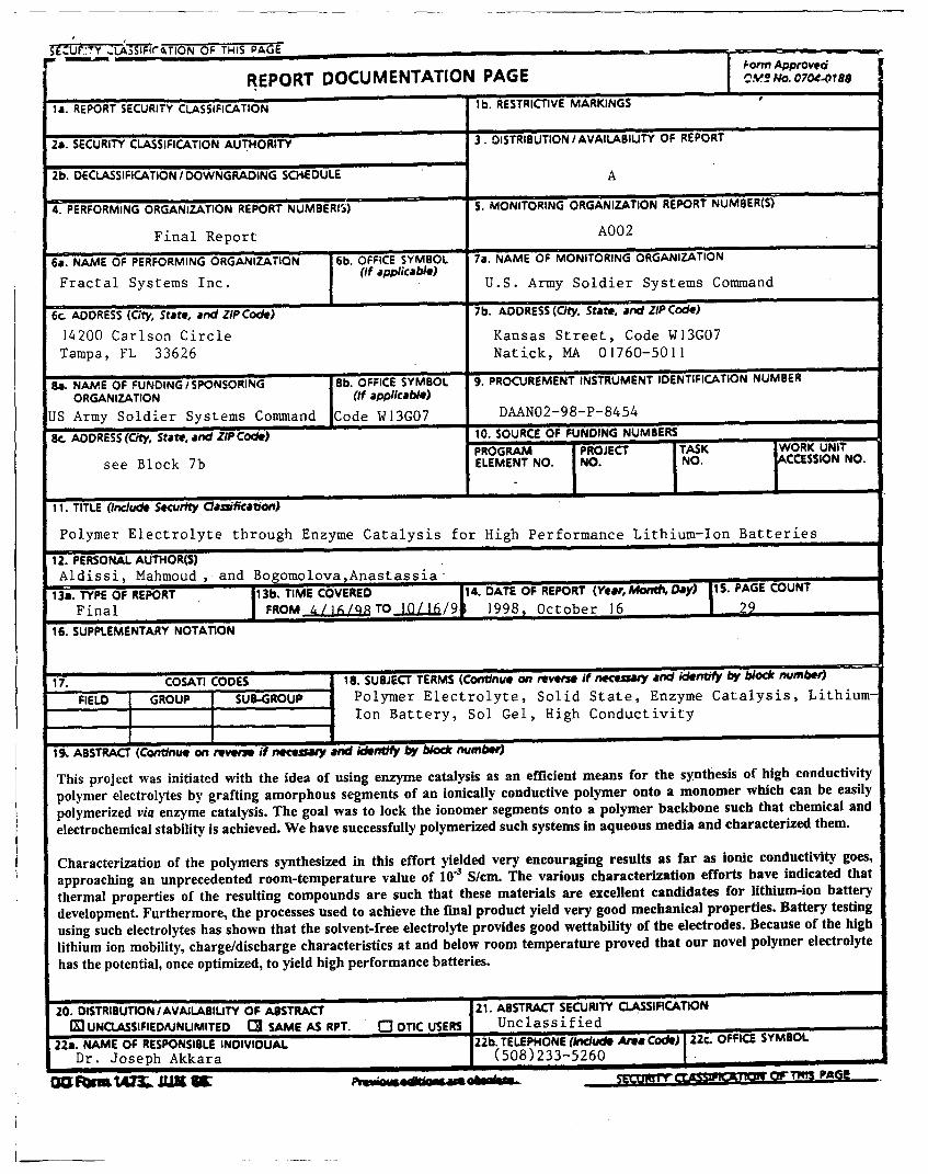
REPORT DOCUMENTATION PAGE
is. REPORT SECURITY CLASSIFICATION lb. RESTRICTIVE MARKINGS
2a. SECURITY CLASSIFICATION AUTHORITY 3. DISTRIBUTION I AVAILABIUTY OF REPORT
2b. DECLASSIFICATION / DOWNGRADING SCHEDULE A
4. PERFORMING ORGANIZATION REPORT NUMBER(5) 5. MONITORING ORGANIZATION REPORT NUMBER(S)
Final Report A002
6a. NAME OF PERFORMING ORGANIZATION 6b. OFFICE SYMBOL 7a. NAME OF MONITORING ORGANIZATION
Fractal Systems Inc. (if applicable) U.S. Army Soldier Systems Command
6c. ADDRESS (City, State, and ZIP Code) 7b. ADDRESS (City, State, and ZIP Code)
14200 Carlson Circle Kansas Street, Code W13G07
Tampa, FL 33626 Natick, MA 01760-5011
Sa. NAME OF FUNDING'/SPONSORING lb. OFFICE SYMBOL 9. PROCUREMENT INSTRUMENT IDENTIFICATION NUMBER
ORGANIZATION (If applicable)
US Army Soldier Systems Command jCode W13G07 DAAN02-98-P-8454
Pc. ADDRESS (Cit,/ State, and ZIP Code) 10. SOURCE OF FUNDING NUMBERSPROGRAM PROJECT TASK WORK UNIT
see Block 7b ELEMENT NO. NO. NO. CCESSION NO.
11. TITLE (Include Security ClawifiCation)
Polymer Electrolyte through Enzyme Catalysis for High Performance Lithium-Ion Batteries
12. PERSONAL AUTHOR(S)Aldissi, Mahmoud , and Bogomolova,Anastassia
13,. TYPE OF REPORT 13b. TIME COVERED [ iF4 DATE OF REPORT (Year, Mowst Day) PAGE COUNT
Final FROM 4/.16/qTO 10/16/9# 1998, October 16 . 2916. SUPPLEMENTARY NOTATION
17. COSATI CODES . . 18. SUBJECT TERMS (Continuo on reverse if neCeuary and iden,,fy by block number)
FIELD GROUP SUB-GROUP Polymer Electrolyte, Solid State, Enzyme Catalysis, Lithium-Ion Battery, Sol Gel, High Conductivity
19. ABSTRACT (Continue on rever" if necesy and identify by block number)
This project was initiated with the idea of using enzyme catalysis as an efficient means for the synthesis of high conductivity
polymer electrolytes by grafting amorphous segments of an ionically conductive polymer onto a monomer which can be easily
polymerized via enzyme catalysis. The goal was to lock the ionomer segments onto a polymer backbone such that chemical and
electrochemical stability is achieved. We have successfully polymerized such systems in aqueous media and characterized them.
Characterization of the polymers synthesized in this effort yielded very encouraging results as far as ionic conductivity goes,
approaching an unprecedented room-temperature value of 10"3 S/cm. The various characterization efforts have indicated that
thermal properties of the resulting compounds are such that these materials are excellent candidates for lithium-ion battery
development. Furthermore, the processes used to achieve the final product yield very good mechanical properties. Battery testing
using such electrolytes has shown that the solvent-free electrolyte provides good wettability of the electrodes. Because of the high
lithium ion mobility, charge/discharge characteristics at and below room temperature proved that our novel polymer electrolyte
has the potential, once optimized, to yield high performance batteries.
20. DISTRIBUTION /AVAILABILITY OF ABSTRACT 21. ABSTRACT SECURITY CLASSIFICATION
M 'UNCLASSIFIED/UNUMITED C3 SAME AS RPT. 0 OTIC USERS Unclassified22s. NAME OF RESPONSIBLE INDIVIDUAL 22b. TELEPHONE (/ndude Ara Code) 22C. OFFICE SYMBOL
Dr. Joseph Akkara (508)233-5260 ,
SEMM,-,, I aIt --Wr OFT•-1S PAGE

Polymer Electrolyte through Enzyme Catalysis for High Performance Lithium-Ion Batteries
Table of Contents
Page
Executive Summary
Purpose of the Research 1
Objectives 2
Approach 2
Results and Discussion 5
Synthesis of the Phenol Monomer Derivative 5
Polymerization of the Phenol Monomer Derivative 5
Sol Gel Electrolyte Preparation 8
Polymer Electrolytes based on Solvent-Free Gels 8
Characterization 8
Structural Properties 8Thermal Properties 11Transport Properties 11
Lithium Ion batteries 21
Conclusions 22
Phase H Outline 25
Commercialization Strategy 25
References 25

List of Figures
1. Schematic of Phenol Polymerization Catalyzed by Horseradish Peroxidase.
2. Schematic Structure of the Proposed Polymer Electrolyte
3. Interconnected Network of the So Gel Polymer Electrolyte
4. Reaction Sequences for the Preparation of the PEG-Phenol Monomer
5. Structure of the Double-Branched PEG2-NHS
6. Proton NMR Spectrum of the PEG 550-Phenol Polymer
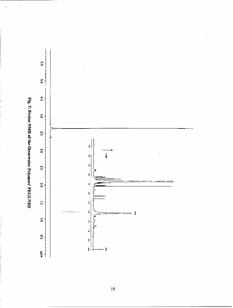
7. Proton NMR Spectrum of the Shearwater Polymers' PEG2-NHS
8. Thermogravimetric Analysis Spectrum of the PEG 550-Phenol Polymer
9. Differential Scanning Calorimetry of the PEG 550-Phenol Polymer
10. Schematic of the Four-Probe (a) and Two-Electrode (b) Conductivity Measurements
11. Equivalent Circuit of the Electrochemical Cell of Figure 10 b
12. Nyquist Plots of the PEG-Phenol Polymer and its Copolymers
13. Current-Voltage Phase Angle Shift of the PEG-Phenol Polymer and its Copolymers
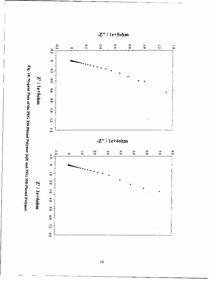
14. Nyquist Plots of the PEG 350-Phenol Polymer (left) and PEG 550-Phenol Polymer
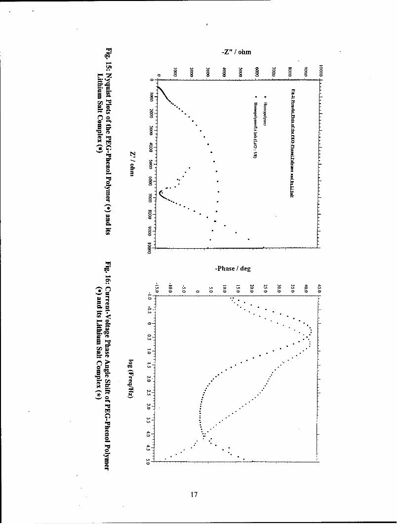
15. Nyquist Plots of the PEG-Phenol Polymer (e) and its Lithium Salt Complex (m)
16. Current-Voltage Phase Angle Shift of PEG-Phenol Polymer (*)and its Lithium Salt Complex (*)
17. Nyquist Plots of PEG-Phenol Polymer Sol Gel Electrolyte under Bias: 0 V (*), 1 V (E), 2 V (o)
18. Current-Voltage Phase Angle Shift of PEG-Phenol Polymer (o) and its Sol Gel Equivalent (*)
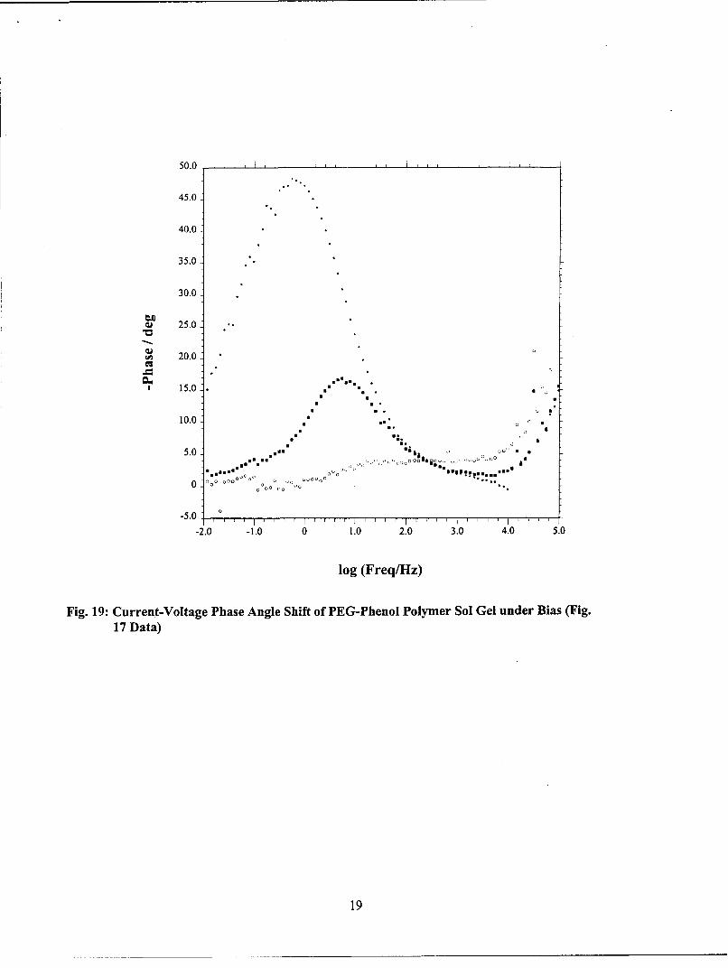
19. Current-Voltage Phase Angle Shift of PEG-Phenol Polymer Sol Gel under Bias (Data of Fig. 17)
20. Cycling of the SS-TiN/Sol Gel Polymer Electrolyte/TiN-SS Cell using Chronoamperometry (left) andChronopotentiometry
21. Cross-sectional View of the Fractal Systems' Lithium Ion Polymer Battery
22. Charge/Discharge Characteristics of Li/Polymer Electrolyte/LiCoO 2 Battery at 200 ýWA/cm 2
23. Discharge Characteristics of Li/Polymer Electrolyte/LiMnO2 Battery at 50 gA/cm2
24. Charge/Discharge Characteristics of Li/Polymer Electrolyte/LiCoO 2 Battery at 50 pA/cm 2 and 10'C
25. Charge/Discharge Characteristics of Li/Polymer Electrolyte/LiMnO 2 Battery at 50 pA/cm 2and 2°C

Executive Summary
This project was initiated with the idea of using alternative means for the synthesis of polymerelectrolytes with high yield, efficiency and ease of the processes used. Enzyme catalysis meets thesecriteria, and was used for this purpose by incorporating amorphous segments of poly (ethylene glycol),PEG, onto a monomer which can be easily polymerized via enzyme catalysis. The goal was to lock thePEG segments onto a polymer backbone such that chemical and electrochemical stability is achieved. Toaccomplish this task, we have substituted the basic monomer with PEG segments of various molecularweights. We have successfully polymerized such systems in aqueous media and characterized them.
Characterization of the polymers synthesized in this effort yielded very encouraging results as far as ionicconductivity goes, approaching an unprecedented room-temperature value of 10-3 S/cm. The variouscharacterization efforts have indicated that although the glass transition temperature (To is low, the meltand decomposition temperatures are high enough for use of such materials in lithium ion batteries in awide temperature range. The low Tg is due to the high mobility of the PEG component, and the goodthermal stability is due to the carrier polymer obtained via enzyme catalysis.
However, we went beyond this point and prepared a proprietary formulation, which takes advantage ofthe collective properties of the different components, and where the PEG segments become much longerthrough this process, without compromising their much-needed amorphous character. A fully solid-statesystem with high fluidity of the PEG segments has resulted.
We have also experimented with novel ionic gels based on our polymers without the incorporation ofsolvents as is usually the case in other efforts which employ propylene carbonate and the likes. Suchmaterials are highly porous, with a strong ionic character, and would be developed further in the Phase IIprogram.
The most direct way to test any material whether it is a good electrolyte or not is to sandwich it betweentwo electrodes, an anode and a cathode, and evaluate the resulting battery. This is what we have done byusing lithium anode and two high-energy cathode materials. In addition to using the appropriateelectrodes, we have chosen to work with a novel current collector, polymer-based and thus thin andflexible. Another important advantage of the latter is that corrosion, experienced with metal currentcollectors, in the long run is avoided. Battery characterization and cycling results between 00C and roomtemperature indicate that our electrolyte has the potential to yield high-energy capacity lithium ionbatteries, which will be marketed in collaboration with our partner who has been producing energystorage devices for a good number of years.

Purpose of the Research
Polymer electrolytes are of prime interest in the development of advanced battery systems. Unfortunately,persistent problems associated with these materials when used with high-energy anodes such as lithiumhave accelerated the pace of this development. Despite setbacks, the quest for a truly solid-state lithiumbattery continues because of the unique design capabilities offered by this type of architecture and thepotential for improved safety in high rate systems.
High conductivity and wide electrochemical stability, as well as compatibility with electrode materials arethree criteria in choosing a suitable electrolyte for practical battery applications. One of the mainproblems encountered with polymer electrolytes is the short cycle life of cells containing these materials.Impedance and polarization studies have implicated passivation of the lithium anode as the reason for theobserved degradation of cell behavior. The passivating film is known to result from reaction between thepolymer electrolyte and lithium. This reaction is fostered by the requirement to operate conventional(although experimental) solid state lithium batteries at temperatures in excess of 1000 C. This operatingcondition is due to the high glass transition temperature (To) of the polymer hosts presently used forpolymer electrolytes. These materials include poly(ethylene oxide), PEO, which is a polycrystalline solidmaterial at room temperature. As a result of this characteristic, polymer electrolytes incorporating suchmaterials exhibit low conductivities (in excess of 10-' S/cm) at room temperature.
Room temperature operation of lithium ion batteries, which use polymer electrolytes having theappropriate thermal, electrical and mechanical characteristics could solve many of the technical problemscurrently faced by this technology. Conventional approaches to the development of new solid polymerelectrolytes have relied heavily on evolutionary changes in the basic recipe of the polymer/salt complex.Introducing solvents such as propylene carbonate or ethylene carbonate has contributed to the ionicconductivity and the better mobility in general of the lithium ion. The increased conductivity is without adoubt a favorable characteristic when compared with their parent solid electrolytes. However, the so-called gel systems are thermodynamically unstable. Gelled electrolytes may undergo solvent exudationupon long storage, especially under open-atmosphere conditions. This phenomenon is known as the"Syneresis" effect {1,2}. Furthermore, the solvents tend to decompose at the high voltages characteristicof lithium-ion batteries and react with the electrodes and the polymer host.
Our Phase I research sought to demonstrate that novel polymer electrolytes can be synthesized byalternative means to what is conventionally known, so that low-Tg PEO segments bound to solid matrixwith improved ionic conductivity can operate in a wide range of temperatures. Lowering the operatingtemperature of solid-state lithium cells would provide a major contribution toward lengthening cycle lifeand improving stability.
The Phase I approach took a new direction in this area of research. Our direction consisted of the designof defined fluid ionic pathways, yet fixed onto a solid-state carrier, thus facilitating cation transport acrossthe polymer electrolyte layer. This is not the case with electrolytes such as PEO where the amorphousregions of the polymer are not directly connected and the amorphous character of the polymer is related toits temperature. We, in turn, have synthesized and characterized a family of novel polymer electrolytesprepared by using the enzyme catalysis technique used by the US Army Soldiers Command team (Natick,MA) {3} of monomers designed for such an application.
The basic concept, which will be given in the approach section, for our research consisted of derivatisingphenol with a PEO segment (in this case PEG) whose length is high enough to efficiently transportlithium ions, and the subsequent polymerization of the phenol derivative through enzyme catalysis. Inthis type of architecture, the phenol segments provide for thermal and mechanical stability of the systemwhile maintaining the fluidity of the fixed PEG units to accommodate lithium ion transport efficiently.

As an extension to this concept, the resulting phenol/PEG polymer is locked in a totally solid-state 3-Dsystem via the sol gel processing technique. The latter technique appears to improve the chemical stabilityof the PEG segments when in contact with lithium. The unique structure of our material has resulted inunprecedented conductivities approaching 10"3 S/cm.
Objectives
This research was initiated to investigate synthesis of improved polymer electrolytes for lithium-ionbattery applications. The overall goal of this effort was to demonstrate that the enzyme-catalyzedpolymerization route is practical and efficient. To achieve this goal and to justify the transition into thesecond Phase of this work, the following specific objectives needed to be accomplished:
"* Demonstrate feasibility of the polymer synthesis where the phenol repeat unit is substituted in the
para position with short PEO segments.
"* Characterize the polymer in terms of thermal and electrical properties.
"* Establish electrolyte characteristics of the polymer/lithium salt complex by measurement of itselectrical characteristics.
" Demonstrate the possibility of fabricating nanocomposites with clays for improving mechanical,thermal and interfacial stability.
" Demonstrate the high room temperature conductivity of the best composition in terms of processing,manufacturability and mechanical integrity.
"" Demonstrate the polymer electrolyte performance in a laminated Li-ion battery design.
Approach
Our approach combines various aspects toward the synthesis of the novel polymer electrolyte. The firstaspect deals with the use of short chain PEG in order to avoid crystallization and increase of Tg of thefinal product. As mentioned above, this will allow the use of the polymer in lithium-ion batteries in awide temperature range. The second aspect concerns the covalent bonding of these short PEG segmentsonto a monomer which typically results in a thermally stable backbone. The monomer chosen here isphenol in order to take advantage of third aspect, which consists of the polymerization of PEG-phenolmonomer via enzyme catalysis as a follow up on the work developed at Natick RD&E Center which usesenzyme-catalyzed reactions for the synthesis of aromatic polymers. In their work, Ayyagari et al. {4}have synthesized and characterized substituted phenol polymers obtained via horseradish peroxidase(Type II) (abbreviated as HRP) catalyzed polymerization in various media. The synthesis route is shownin Fig. 1 for illustration purposes.
R R
H202
OH OH
R = ethyl, phenyl
Fig. 1: Schematic of Phenol Polymerization Catalyzed by Horseradish Peroxidase (Ref. 3)
2
In our approach, the phenol monomer is substituted in the para-position with a short PEG. Based on theintrinsic electrolytic properties of PEG, eight repeat units are enough to provide the interfacialcharacteristics needed for efficient Li÷ diffusion. However, shorter segments might be enough whenanchored to another polymer repeat unit such as phenol. The polymer having phenol as the repeat unit ispolycrystalline in nature. When substituted with an aliphatic group, the amorphous character is enhanced.Therefore, an optimal segment length of the PEG needed to be used such that the resulting polymer ismostly amorphous. The appropriate segment length has been narrowed down during the Phase I, and willbe optimized further during the Phase II effort. The structure of the optimized polymer electrolyte as aresult of the Phase I work is shown above in Fig. 1 with
= -(- 0 CH2CH2-#m 0
(m = 8-16, which corresponds to a PEG segment molecular weight of 350-700).
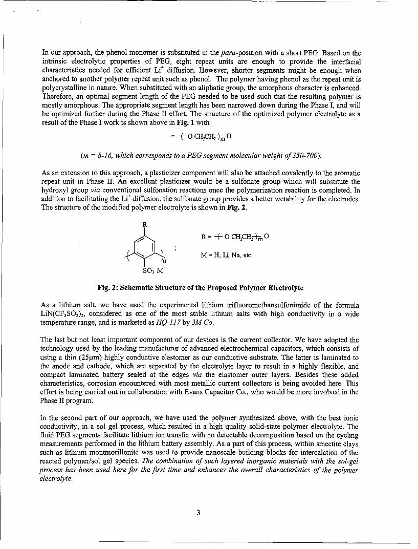
As an extension to this approach, a plasticizer component will also be attached covalently to the aromaticrepeat unit in Phase II. An excellent plasticizer would be a sulfonate group which will substitute thehydroxyl group via conventional sulfonation reactions once the polymerization reaction is completed. Inaddition to facilitating the Li÷ diffusion, the sulfonate group provides a better wetability for the electrodes.The structure of the modified polymer electrolyte is shown in Fig. 2.
RR oCH2CH2 m 0
M =H, Li, Na, etc.n
SO3 M+
Fig. 2: Schematic Structure of the Proposed Polymer Electrolyte
As a lithium salt, we have used the experimental lithium trifluoromethansulfonimide of the formulaLiN(CF3SO3)2, considered as one of the most stable lithium salts with high conductivity in a widetemperature range, and is marketed as HQ-11 7 by 3M Co.
The last but not least important component of our devices is the current collector. We have adopted thetechnology used by the leading manufacturer of advanced electrochemical capacitors, which consists ofusing a thin (25ýtm) highly conductive elastomer as our conductive substrate. The latter is laminated tothe anode and cathode, which are separated by the electrolyte layer to result in a highly flexible, andcompact laminated battery sealed at the edges via the elastomer outer layers. Besides these addedcharacteristics, corrosion encountered with most metallic current collectors is being avoided here. Thiseffort is being carried out in collaboration with Evans Capacitor Co., who would be more involved in thePhase II program.
In the second part of our approach, we have used the polymer synthesized above, with the best ionicconductivity, in a sol gel process, which resulted in a high quality solid-state polymer electrolyte. Thefluid PEG segments facilitate lithium ion transfer with no detectable decomposition based on the cyclingmeasurements performed in the lithium battery assembly. As a part of this process, within smectite clayssuch as lithium montmorillonite was used to provide nanoscale building blocks for intercalation of thereacted polymer/sol gel species. The combination of such layered inorganic materials with the sol-gelprocess has been used here for the first time and enhances the overall characteristics of the polymerelectrolyte.
3
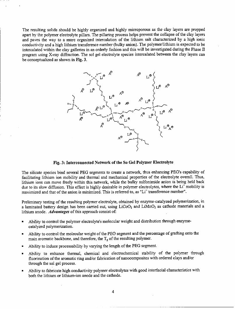
The resulting solids should be highly organized and highly microporous as the clay layers are proppedapart by the polymer electrolyte pillars. The pillaring process helps prevent the collapse of the clay layersand paves the way to a more organized intercalation of the lithium salt characterized by a high ionicconductivity and a high lithium transference number (bulky anion). The polymer/lithium is expected to beintercalated within the clay galleries in an orderly fashion and this will be investigated during the Phase IIprogram using X-ray diffraction. The sol gel electrolyte species intercalated between the clay layers canbe conceptualized as shown in Fig. 3.
•N° o•" AO Ae Li@ •
ALi Li 0
Ae '-Ae
~ io
0 0
U Ae __/-- Ae oA
NO 0~ Li~eALLfD
Fig. 3: Interconnected Network of the So Gel Polymer Electrolyte
The silicate species bind several PEG segments to create a network, thus enhancing PEG's capability offacilitating lithium ion mobility and thermal and mechanical properties of the electrolyte overall. Thus,lithium ions can move freely within this network, while the bulky sulfonimide anion is being held backdue to its slow diffusion. This effect is highly desirable in polymer electrolytes, where the Li÷ mobility ismaximized and that of the anion is minimized. This is referred to, as "Li÷ transference number".
Preliminary testing of the resulting polymer electrolyte, obtained by enzyme-catalyzed polymerization, ina laminated battery design has been carried out, using LiCoO2 and LiMnO2 as cathode materials and alithium anode. Advantages of this approach consist of:
* Ability to control the polymer electrolyte's molecular weight and distribution through enzyme-catalyzed polymerization.
* Ability to control the molecular weight of the PEO segment and the percentage of grafting onto themain aromatic backbone, and therefore, the Tg of the resulting polymer.
* Ability to induce processability by varying the length of the PEG segment.
* Ability to enhance thermal, chemical and electrochemical stability of the polymer throughfluorination of the aromatic ring and/or fabrication of nanocomposites with ordered clays and/orthrough the sol gel process.
* Ability to fabricate high conductivity polymer electrolytes with good interfacial characteristics with
both the lithium or lithium-ion anode and the cathode.
4
* Ability to fabricate batteries with versatile designs due to the flexibility of the different components,particularly, the electrolyte and the current collector, with the latter being low cost, light weight andoutstanding anticorrosion properties.
Results and Discussion
Synthesis of the Phenol Monomer Derivative
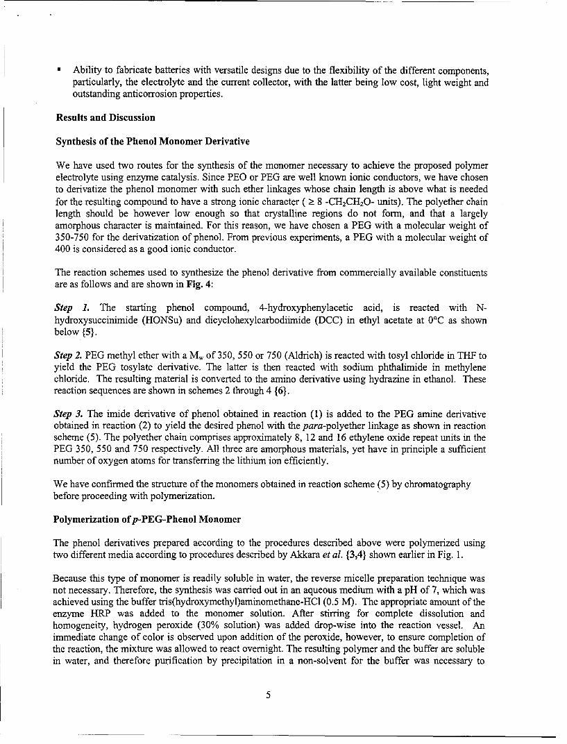
We have used two routes for the synthesis of the monomer necessary to achieve the proposed polymerelectrolyte using enzyme catalysis. Since PEO or PEG are well known ionic conductors, we have chosento derivatize the phenol monomer with such ether linkages whose chain length is above what is neededfor the resulting compound to have a strong ionic character ( > 8 -CH2CH20- units). The polyether chainlength should be however low enough so that crystalline regions do not form, and that a largelyamorphous character is maintained. For this reason, we have chosen a PEG with a molecular weight of350-750 for the derivatization of phenol. From previous experiments, a PEG with a molecular weight of400 is considered as a good ionic conductor.
The reaction schemes used to synthesize the phenol derivative from commercially available constituentsare as follows and are shown in Fig. 4:
Step 1. The starting phenol compound, 4-hydroxyphenylacetic acid, is reacted with N-hydroxysuccinimide (HONSu) and dicyclohexylcarbodiimide (DCC) in ethyl acetate at 0°C as shownbelow {5}.
Step 2. PEG methyl ether with a Mw of 350, 550 or 750 (Aldrich) is reacted with tosyl chloride in THF toyield the PEG tosylate derivative. The latter is then reacted with sodium phthalimide in methylenechloride. The resulting material is converted to the amino derivative using hydrazine in ethanol. Thesereaction sequences are shown in schemes 2 through 4 {6}.
Step 3. The imide derivative of phenol obtained in reaction (1) is added to the PEG amine derivativeobtained in reaction (2) to yield the desired phenol with the para-polyether linkage as shown in reactionscheme (5). The polyether chain comprises approximately 8, 12 and 16 ethylene oxide repeat units in thePEG 350, 550 and 750 respectively. All three are amorphous materials, yet have in principle a sufficientnumber of oxygen atoms for transferring the lithium ion efficiently.
We have confirmed the structure of the monomers obtained in reaction scheme (5) by chromatographybefore proceeding with polymerization.
Polymerization of p-PEG-Phenol Monomer
The phenol derivatives prepared according to the procedures described above were polymerized usingtwo different media according to procedures described by Akkara et al. {3,4} shown earlier in Fig. 1.
Because this type of monomer is readily soluble in water, the reverse micelle preparation technique wasnot necessary. Therefore, the synthesis was carried out in an aqueous medium with a pH of 7, which wasachieved using the buffer tris(hydroxymethyl)aminomethane-HC1 (0.5 M). The appropriate amount of theenzyme HRP was added to the monomer solution. After stirring for complete dissolution andhomogeneity, hydrogen peroxide (30% solution) was added drop-wise into the reaction vessel. Animmediate change of color is observed upon addition of the peroxide, however, to ensure completion ofthe reaction, the mixture was allowed to react overnight. The resulting polymer and the buffer are solublein water, and therefore purification by precipitation in a non-solvent for the buffer was necessary to
5

isolate the polymer. The resulting material was collected by evaporation of the solvent. The polymerconsisted of a gel with a slight yellow color.
COOHO
DCC + HONSu >" 0 (1)
OC, Ethyl Acetate
OH OH
TosClCH 30(CH 2 CH 2 O). H - * CH30(CH 2 CH 2 0)Tos (2)
THF
0
Phthalimide" Na +CH 30(CH 2 CH 2 0),Tos) • CH30(CH 2 CH 20). (3)
CH2 Cl20
00
HydrazineCH 30(CH 2 CH 2 O)nN > P- CH30(CH 2 CH 2 O)n-I CH Z CH 2 NH 2 (4)
EtOH0
0
O-Ný__O& + CH30(CH 2 CH 2O)n-1 CH 2 CH 2 NH 2
OH
0
NHCH 2 CH 20(CH 2 CH 2 O)n- CH3 The size of the PEO group was chosensuch that the resulting polymer is stillamorphous for better Li+ transfer. j
H
Fig. 4: Reaction Sequences for the Preparation of the PEG-Phenol Monomer
6

The second medium used consisted of dioxane/water mixture (80/20) in which the monomer is readilysoluble as well. The polymerization procedure is the same as in the aqueous medium. The resultingpolymer was collected using the procedure mentioned above. Unlike the one prepared in the aqueousmedium, this polymer consisted of a lower viscosity gel than the previous preparation. This is indicativeof lower molecular weights.
In addition to the PEG-phenol homopolymers, we have prepared two copolymers where the comonomeris p-ethoxyphenol and p-phenylphenol known to undergo polymerization individually as described inreferences 3 and 4. Because these two monomers are insoluble in water, the dioxane/water mixture wasused as the polymerization medium. The copolymers were prepared using similar conditions to thoseused for the PEG-phenol homopolymer, with a comonomer molar ratio of 1:1. The resulting materials inboth cases consisted of a low viscosity gel similarly to that of the homopolymer prepared in the samemedium. Here again, a low molecular weight is probably the cause of such morphology.
Thefirst route used to synthesize the PEG-based polymer electrolyte through enzyme catalysis involvedthe synthesis of the PEG-phenol monomer first then polymerization via HRP catalysis. The secondmethod we have investigated, consists of polymerization of the phenol derivative via HRP catalysis, thensubstituting the phenol repeat unit in the polymer with PEG-based segments. For this purpose, we haveused aminophenol as the starting material. This monomer has been successfully made using a 75/25volume ratio of dioxane/water as the polymerization medium, and HRP/hydrogen peroxide as the catalyst.The resulting polymer is then reacted with an ester of methoxypoly (ethylene glycol) modified lysineavailable from Shearwater Polymers (referred to as PEG2-NHS), which has the structure shown in Fig. 5:
0
mPEG-0 NHC - NH
oI _h
mPEG--O--C -- NH C O N
00
Fig. 5: Structure of the Double-Branched PEG2-NHS
The molecular weight of the PEG segment in each branch is 5000, which results in a total molecularweight of the modified lysine of 11,136. Because the ionic conductivity properties are intrinsic to the PEGsegment, the 5000 molecular weight is well suited for our application. This compound melts at 59°Caccording to our differential scanning calorimetry (DSC) measurements. Following reaction withpoly(aminophenol), an endothermic peak at 56.8°C was obtained in the DSC and corresponds to themelting point of the PEG-aminophenol copolymer. The melting point remains practically unchanged. Thismight be due to the structural characteristics being dominated by the PEG portion. Furthercharacterization of the synthesized polymer was not pursued due to its insolubility in water or commonorganic solvents. It is suspected that substitution of the aminophenol repeat unit was too small using thissynthesis route.
7

Sol Gel Electrolyte Preparation
Sol gels seem to be the most promising electrolyte materials from all aspects of this research. They aresimple to synthesize from cheap, commercially available materials, and comprise tetraethoxysilane(TEOS), the PEG synthesized as described in the previous sections, lithium salt. In our proprietaryformulation, a lithium montmorillonite is added for ordering purposes and an added mechanical integrity.To this formulation, we added lithium aluminate (y-LiA10 2) to improve the interfacial stability betweenthe electrolyte and the lithium anode.
TEOS and water were sonicated together for one hour. Our PEG and the lithium salt HQ-117 mixture(O/Li = 8/1) was added to the mixture and sonicated for an additional hour. The sol gel mixture at thispoint is a cloudy liquid with the PEG phase partly separated from the silicate phase. A small amount of1M HCI was added to the sol gel to give a single-phase cloudy solution, and continued sonication foranother hour. The sol gel was cast in a Teflon-coated dish and heated in a vacuum oven at 100°C forseveral hours. The sample was then taken out of the oven once it cooled down to room temperature.Translucent flexible films resulted from this process.
Polymer Electrolytes based on Solvent-Free Gels
Poly(ethylene glycol) methacrylate with an average molecular weight of 360 was polymerized in the formof a gel using the appropriate amounts of monomer, ammonium persulfate and N,N,N',N'-tetramethylethylenediamine (TEMED) in water. The monomer's structure is such that there are six repeatunits of PEG. Therefore, the polymer resulting from this step alone is expected to yield a reasonable ionicconductivity due to the inter-connected network of the gel, and therefore, the reasonably good interactionbetween the PEG segments. We have characterized the gel using electrochemical impedance spectroscopyto determine the conductivity of the polymer gel alone and when combined with the lithium salt used inall our experiments. This work was initiated for versatility reasons, and will be combined in the Phase IIprogram with the PEG-phenol polymer obtained via enzyme catalysis. Our plan will be to form themethacrylate gel in the presence of our polymer so that the latter is incorporated in the gel's network.
Characterization
Structural Characterization
The structure of the polymers obtained via enzyme catalysis was investigated by proton NMR (XeroxResearch Center, Missisauga, Ontario) in CDC13/TMS. A characteristic spectrum of a p-PEG-phenolpolymer, where the PEG segment has a molecular weight of 550 is shown in Fig. 6. The dominant peakscentered at 3.65 ppm correspond to the protons of the PEG segments. The two protons of the phenolrepeat unit (in the meta position vis-ci-vis the PEG group) are characterized by a shift at 6.7 and 7.2 ppmas can be seen in the insert (X 64). Due to the low intensity of the aromatic protons compared to those ofPEG, integration was difficult. The PEG polymer obtained from Shearwater Polymers in which each PEGsegment has a molecular weight of 5000 was used as a reference for the peaks observed in our polymer.Fig. 7 shows the spectrum of PEG2-NHS in which the PEG protons are observed at the same shift foundfor our polymer (3.65 ppm). The insert of the latter figure (X 128) shows the rest of the peaks, whichcorrespond, to the remaining protons in the structure. It is important to note that a water peak (1.9 ppm) isfound in the PEG2-NHS while this peak is absent in our polymer. This could be due to the hydrophobicnature of the phenol repeat unit, which is a desirable property in an electrolyte system intended for use inlithium ion batteries.
The molecular weight of the above polymer was determined using GPC with polystyrene being thestandard at Xerox Research Center. The measurement, in the same solvent as for NMR (CHC13), yielded a
8

PO
0
0
U, 1
(11�31
(3'0
(31
-J
-Io00
C
0
-Ic/I
C
I")
0
0
10
molecular weight of 8963 (measurements performed at Xerox research Center). This corresponds toapproximately 13 repeat units of the PEG-phenol monomer whose structure was shown earlier. The PEGportion constitutes 80% of the molecular weight, and therefore, such a polymer is structurally ideal forionic conduction.
Thermal Properties
Thermogravimetric analysis (TGA) was conducted on our 550 polymer. The result is displayed in Fig. 8.The polymer exhibits an excellent stability, with no decomposition before 215'C. DSC (Fig. 9) wasperformed as well. Although the baseline is not very good, one can observe several broad peakscorresponding to exothermic reactions from -30'C to 22'C. These features are typically observed inamorphous PEG and correspond glass transition that is not well defined, but is characteristic of thefluidity of the PEG segments. The exothermic peaks observed at higher temperatures correspond probablyto the softening of the PEG-phenol copolymer segments. An endothermic peak, not clearly assigned atthis point, is observed at 25°C, and another at 721C, which corresponds to the melting point of the PEG-phenol polymer, similarly to what was obtained by capillary tubing melt temperature measurement. Thisis encouraging since the fluidity of the PEG segments is necessary for ionic conduction, while the rigidityof the backbone is required for thermal stability of the electrolyte system. Such fluidity will bedemonstrated in the battery characterization section at temperatures below RT. TGA and DSC wereobtained at Illinois State Univ., Normal, IL, as well as at Xerox Research Center.
Transport Properties
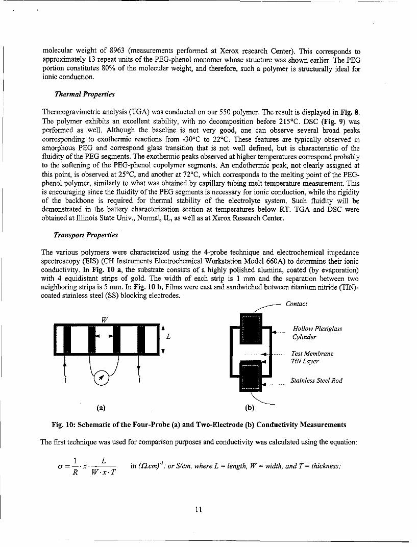
The various polymers were characterized using the 4-probe technique and electrochemical impedancespectroscopy (EIS) (CH Instruments Electrochemical Workstation Model 660A) to determine their ionicconductivity. In Fig. 10 a, the substrate consists of a highly polished alumina, coated (by evaporation)with 4 equidistant strips of gold. The width of each strip is 1 mm and the separation between twoneighboring strips is 5 mm. In Fig. 10 b, Films were cast and sandwiched between titanium nitride (TIN)-coated stainless steel (SS) blocking electrodes.
Contact
WA Hollow Plexiglass
L Cylinder
_- Test MembraneTiN Layer
Stainless Steel Rod
(a) (b)
Fig. 10: Schematic of the Four-Probe (a) and Two-Electrode (b) Conductivity Measurements
The first technique was used for comparison purposes and conductivity was calculated using the equation:
1'= 1 x. L in (2. cm)-'; or S/cm, where L = length, W = width, and T = thickness;
R W.x.T
11

100
0,40 140 240 340 440
Temperature (°C)
Fig. 8: Thermogravimetric Analysis Spectrum of the PEG 550-Phenol Polymer
-0.5
.- 1 .o
-1 .5-1-50 0 50 100
Temperature (*C)
Fig. 9: Differential Scanning Calorimetry of the PEG 550-Phenol Polymer
12
However, most of our measurements used the second technique because it provides other electrochemicalcharacteristic besides ionic conductivity values. EIS measurements were run between 0.01 or 0.1 and 105
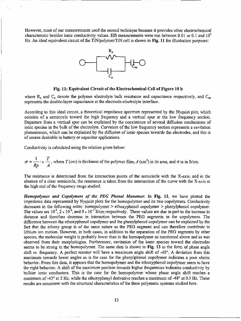
Hz. An ideal equivalent circuit of the TiN/polymer/TiN cell is shown in Fig. 11 for illustration purposes:
Rp
Cp
Fig. 11: Equivalent Circuit of the Electrochemical Cell of Figure 10 b
where Rp and Cp denote the polymer electrolyte bulk resistance and capacitance respectively, and Cerepresents the double-layer capacitance at the electrode-electrolyte interface.
According to this ideal circuit, a theoretical impedance spectrum represented by the Nyquist plot, whichconsists of a semicircle toward the high frequency and a vertical spur at the low frequency section.Departure from a vertical spur can be explained by the coexistence of several diffusion mechanisms ofionic species in the bulk of the electrolyte. Curvature of the low frequency section represents a cavitationphenomenon, which can be explained by the diffusion of ionic species towards the electrodes, and this isof course desirable in battery or capacitor applications.
Conductivity is calculated using the relation given below:
1 T
or = I- .x-, where T(cm) is thickness of the polymer film, A (cm 2) is its area, and a is in S/cm.Rp A
The resistance is determined from the intersection points of the semicircle with the X-axis, and in theabsence of a clear semicircle, the resistance is taken from the intersection of the curve with the X-axis atthe high end of the frequency range studied.
Homopolymer and Copolymers of the PEG Phenol Monomer: In Fig. 12, we have plotted theimpedance data represented by Nyquist plots for the homopolymer and its two copolymers. Conductivitydecreases in the following order: homopolymer > ethoxyphenol copolymer > phenylphenol copolymer.The values are 10', 2 x 10⁻⁶, and 9 x 10⁻⁷ S/cm respectively. These values are due in part to the increase indistance and therefore decrease in interaction between the PEG segments in the copolymers. Thedifference between the ethoxyphenol copolymer and the phenylphenol copolymer can be explained by thefact that the ethoxy group is of the same nature as the PEG segment and can therefore contribute tolithium ion motion. However, in both cases, in addition to the separation of the PEG segments by otherspecies, the molecular weight is probably lower than in the homopolymer as mentioned above and as wasobserved from their morphologies. Furthermore, cavitation of the ionic species toward the electrodesseems to be strong in the homopolymer. The same data is shown in Fig. 13 in the form of phase angleshift vs. frequency. A perfect resistor will have a maximum angle shift of -45'. A deviation from thismaximum towards lower angles as is the case for the phenylphenol copolymer indicates a poor ohmicbehavior. From this data, it appears that the homopolymer and the ethoxyphenol copolymer seem to havethe right behavior. A shift of the maximum position towards higher frequencies indicates conductivity bybulkier ionic conductors. This is the case for the homopolymer whose phase angle shift reaches amaximum of -43' at 2 Hz, while the ethoxyphenyl derivative reaches a maximum of -48' at 0.5 Hz. Theseresults are consistent with the structural characteristics of the three polymeric systems studied here.
13

"-Z" / le+4ohm
tJ
o v
eD 00
-= -- -, .
o__ = ..
= ,- :"
00 I
0 • 0
Ito 1
• •-"•
02@
-•-. ..) N L . * S UU) 0 . 0 U. 0 a U
- 0 0 0 0 0 0 0 0 0 14
This does not mean that copolymers should be ruled out, because their ionic conductivity and their overallproperties depend on the comonomer ratio and the length of the PEG segment. These two parameters areinter-related, and such experiments are beyond the scope of this study. Because the copolymers madeusing the PEG-phenol derivative in combination with ethoxy- and phenyl phenol comonomers using a 1:1ratio yielded lower ionic conductivity than that of the PEG-phenol homopolymer, we decided at this stageto proceed with the latter material for further electrolyte related studies. Depending on their conductivity,the best homopolymer in terms of the PEG segment molecular weight will be chosen for further workincluding a combination of two of these materials. The latter approach will be optimized in the Phase IIprogram. The PEG-phenol polymer where the PEG segment has a molecular weight of 350 and 750 wereevaluated as well. As far as impedance analysis and conductivity measurements go, the 550 polymer has ahigher conductivity than the 350 by approximately 5 times as can be seen from the Nyquist plots shownin Fig. 14. However, there was practically no difference between the 550 and 750 polymers, andtherefore, any of the latter two derivatives is a potential candidate as a polymer electrolyte, but a 350polymer in a sol gel matrix as explained in the "approach" section should work well.
Lithium Salt/Polymer Electrolyte Complex: Fig. 15 shows the Nyquist plots for the homopolymer and amixture of the homopolymer with the high Li÷ mobility salt, lithiumtrifluorosulfonimide (3M). Themixture is made in solution, since both components are water soluble, for homogeneity purposes. Theratio is such that the O/Li ratio is 1/8. This ratio has shown the best performance in terms of Li÷conduction in PEO-based electrolytes. The conductivity value obtained from the plot of the lithium saltblend is 8 x 10⁴ S/cm, which represents an increase of almost two orders of magnitude compared to thepure homopolymer. A conductivity approaching 10-3 S/cm is considered as a major advance in this area.Fig. 16 shows the phase angle shift vs. frequency of the above data. The maximum shift (-431) is similarfor the homopolymer with and without the lithium salt, indicating good resistor/conductor properties.However, and as expected, the maximum is shifted slightly from 2 Hz to 5 Hz due to the interaction oflithium ions with the PEG oxygen atoms, thus making it look bulkier species. The shoulder, whichrepresents a maximum at 100-200 Hz, is probably due to the low mobility of the bulky sulfonimideanions. This latter effect is desirable since the lithium ion motion is the one that is needed in the directionof the anode, and this of course should result in an increase of the lithium ion transference number.
Sol Gel Polymer Electrolyte: A sol gel polymer electrolyte formulation consisting of the componentsmentioned in the "approach" section and based on the 550 polymer synthesized in this work was alsostudied. The lithium salt is the same as that used with the homopolymer studied above. Fig. 17 showsNyquist plots of the material at OV and when 1 V and 2 V are applied to the TiN/Electrolyte/TiN cell.Conductivity, determined from the first semi-circle becomes higher with the increased voltage,correspond to an ohmic behavior, with a value at no bias being approximately 5 x 1 0 -4 S/cm. This issimilar to what was obtained earlier with the homopolymer/lithium salt combination (8 x 10⁴ S/cm). Inaddition to the increase in ionic conductivity with voltage, which is a phenomenon that is necessary forbattery operation, cavitation is increased as expected here again. The phase angle shift of this sol gelformulation is compared to that of the homopolymer shown earlier in Fig. 16 since the same polymer isused in both formulations. This data is shown in Fig. 18. A slight downward shift of the maximum for thesol gel is obtained. This is due to the confinement of the PEG segments by the silicate species viacovalent bonding. Furthermore, and this is quite interesting, the shoulder which corresponds to the bulkyanions observed in the case of the homopolymer electrolyte, is absent in the sol gel plot. High lithium iontransference numbers should result from such a formulation. The phase angle shift (Fig. 19) decreases asthe voltage is increased. This is indicative that the current and voltage become closer to being in phase asis observed for the case when a 2 V bias is applied. This means that the current is being produced due tothe lithium ion mobility alone rather than that of the ion plus the ion-lattice interaction. Charge/Dischargecycles were conducted using chronoamperometry and chronopotentiometry as shown in Fig. 20 (10 and25 cycles respectively). The symmetric character of these curves is due to the symmetric construction ofthe cell. Charge and discharge times are similar due to this reason and the homogeneity of the electrolyte.
15
-Z" Ile+5ohm
C 0 0a
00
0 *
le oh
00
+ *16
-Z" /ohm
cin
cJ. .0
0**
["0 0
eD -
•- - 0
C -°
C S
0A
M. .w
rA0CD0
>0
M'0CD
01

-Z" /le+4ohm
CL 0
rr0
- '0 -
-Phase /deg
M Ir
to
-e *
CO)~
18
50.0'
45.0
40.0
35.0
30.0
ۥ 25.0
w, 20.0
15.0 - *" S.. o'S
S• S. .J S
10.0 5 5
1o.0- S S.
"... .0 ...
S• oo,.. .i •
0 o ... ooooo
-5.0 I
-2.0 -1.0 0 1.0 2.0 3.0 4.0 5.0
log (Freq/Hz)
Fig. 19: Current-Voltage Phase Angle Shift of PEG-Phenol Polymer Sol Gel under Bias (Fig.17 Data)
19

Current I le-5A
CC
.CD
o -
CC
Potential! V
cn ci c i CD c in cni -° ic
00
20

Furthermore, the magnitude of the current or voltage vs. time in both techniques remains the sameregardless of the cycle number. This means that the electrolyte is stable during this cycling procedure.
Polymer Electrolytes based on Solvent-Free Gels: This is a preliminary evaluation of the gels preparedas described in the synthesis section. EIS analysis was carried out for the polymer gel as-synthesizedwithout the incorporation of our PEG-phenol polymer, and with the lithium salt such that the molar ratioof Li/O is 1/8. The ionic conductivity determined from the Nyquist plots was determined to beapproximately 10-6 S/cm for the polymer gel and 5 x 10. S/cm for the polymer gel/lithium salt. Thesenumbers could be substantially improved once our polymer is incorporated within the gel duringformation of the latter. This process will ensure that the PEG segments will be locked in the gel matrixand be allowed to interact with the six PEG repeat units of the gel proper. This effort would beinvestigated further in the Phase H program. These gels are flexibility and tough due to the networkformed during gelation in the conditions we have used. Other advantages include, excellent wetability ofthe electrodes, absence of solvents (as is well-known in "polymer gel electrolytes") and ease offabrication
Lithium Ion Battery:
According to impedance analysis and four-probe measurements, the highest bulk ionic conductivity of ourpolymer electrolyte was found to be 8 x 10⁻⁴ S/cm as mentioned above. This value was obtained with theexperimental 3M HQJ 17 salt, which is being used in the current 3M polymer batteries. With such a levelof conductivity, a polymer electrolyte layer thickness can be anywhere from few ptms to 1 mm. Ingeneral, an electrolyte layer with a conductivity of 10-6 S/cm, is considered good for lithium ion batteries,as long as it's thickness does not exceed few pims. Since our electrolyte has a conductivity of the order of10. S/cm, and could still be improved, the layer thickness can be as thin as 1 j.rm and as thick as fewmillimeters. This is particularly interesting due to the fact that the material can easily be formed into thinfilms with good wetability.
The batteries were assembled using a carbon-filled elastomer (used by Evans Capacitor Co. in theirelectrochemical capacitors) as the conductive substrate and current collector. The polymer electrolytewas then deposited as a thin layer (approx. 100 im) onto the cathode material, which consisted of LiCoO 2
in one case and LiMnO2 in another case. Both are available from E-Tek Co., Natick, MA. The lithiumanode (Aldrich) was placed onto the coated cathode. The anode/electrolyte/cathode assembly wassandwiched between two current collector sheets (Evans conductive elastomer) and heat-sealed at thenon-conductive periphery provided by a sealant (Fig. 21). With such a construction, good contact isensured between the different components. This assembly was carried out in a glove bag under nitrogento avoid passivation of the electrodes during testing. The advantage of such an assembly is the possibilityof manufacturing of different designs including stacking of various cells or the rolled-type battery due tothe good flexibility of its various components. Battery testing was performed using chronopotentiometryand other electrochemical techniques.
Conductive Elastomer21 Li Anode
Polymer ElectrolyteLiCoO, or LiMnO, Cathode Sealant
Conductive Elastomer
Fig. 21: Cross-sectional View of the Fractal Systems' Lithium Ion Polymer Battery
Room-Temperature (RT) Studies: Using LiCoO 2 as the cathode material, the flexible polymer batteryhad an open circuit voltage (Vo) of 3.7 V vs. lithium (used as the anode and reference electrode). The
21

battery was charged and discharged at various current densities. We wanted to find out whether it couldwithstand cycling, first at room temperature, using high current densities, which would make itcompetitive with existing technology. Fig. 22 shows two charge and discharge cycles, cycle # 1 and cycle# 30, at 200 j4A/ cm 2. The battery was allowed to charge and discharge at all cycles for 120 seconds.First, It s important to note that very little difference is observed between the first and 30th cycles. Thisindicates stability of the battery and absence or minimal side reactions occurring between the electrolyteand the lithium metal, as is usually the case with most polymer electrolytes. Second, the coulombicefficiency calculated from the area under the charge and discharge curves for each cycle is approximately95%. This is an excellent number for a solid-state polymer battery. Third, a 2-minute discharge ends witha voltage of 2.4 V at the first cycle and 1.7 V at the 30th cycle. Ending up with such voltages means thatthe battery has a good discharge capacity. Fourth, The charge and discharge curves, after the initialincrease or decrease of the potential respectively, are flat. Therefore, we consider such cells as constantpotential batteries, and this is typical of lithium ion batteries.
LiMnO 2 was used in the second type of battery as the cathode material. Here again, the coulombicefficiency was very good and comparable to that of the previous one. The discharge curves at roomtemperature for cycles # 3 and 4 are shown in Fig. 23. The V,, of such cell is 3.45V vs. lithium. Thedischarge was conducted using a 50 gA/ cm 2 discharge rate for one hour. As can be seen from theseplots, the voltage at the end of a long-term discharge is 2.65 V, a value which is quite good, and indicatesthat the battery could be discharged at such current density for much longer periods of time. Here again,the fact that the discharge curve stays flat after the initial decrease in potential is indicative of the cell'sexcellent characteristics during discharge, with the absence of side reactions. The LiMnO 2-based cellseems to offer a higher charge capacity and stability than the previous one.
Studies at Temperatures < RT: Although, this study is one of the focal points to be stressed in the PhaseII program, we wanted to conduct an evaluation of our battery systems at temperatures lower than RT.Charge/discharge studies were conducted on the same cells used for the RT studies. Fig. 24 shows theseresults, obtained using chronopotentiometry, for the LiCoO 2 system at 1 0°C up to 10 cycles. A dischargecurrent of 50 pA/cm 2 was used for 30-min charge and 30-min discharge steps. As can be noticed fromthese rsults, there is very little polarization upon cycling. The potential decreases - 2.2 V vs. Li then staysflat for the remainder of the discharge period, which is the expected characteristic. The LiMnO 2 systemwas studied as well. In Fig. 25, we plotted the charge/discharge cycles at 50 A/cm 2 for 30 min per stepat 2°C. The potential becomes flat after few minutes and the final potential after 30 minutes is 1.9 V at theend of the 1st discharge. This potential is decreased to 1.3 V at the end of the 15th discharge. Thesepolarization figures are promising considering the low temperature performance. The coulombicefficiency upon cycling is good here as well. It is important to note that the flat behavior of the dischargecurves starts immediately at discharge. This means that the battery can be rated at the voltage given by theaverage value of the flat sequence of the curve. Also, the charge capacity is quite high, considering thatdischarge stays flat for longer periods of time.
Conclusions
Based on the various studies we have carried out in this Phase I program, we have demonstrated thatpolymer electrolytes can be prepared efficiently and at low cost using environmentally benign startingmaterials via non-conventional synthesis means, namely, through enzyme catalysis. A conductivityapproaching 10-3 S/cm for a totally solid-state system (solvent-free) is unprecedented. It is considered as aviable number for justifying further development towards market potential. The use of the polymers,when combined with the appropriate lithium salt, as a stand-alone system, or in the form of a sol gelmaterial, in lithium ion batteries has been successfully demonstrated between 0°C and RT. The following
22

- 1 . 2 5 0 - 7 --
Disch # I-1.750 - ------
-2.250 -
-3.750 -tut
-3. 750-
-4.250
-4.750 -#
Chge # 30•
-5.250 I II 1 1-30.00 -10.00 ±0.00 30.00 50.00 70.00 90.00 ±10.00 230.00
t (s)
Fig. 22: Charge/Discharge Characteristics of Li/Polymer Electrolyte/LiCoO 2 Battery at 200 PXcm2
3.580
3.480
3.300
3.200
3.108 -Disch #f 3Disch # 4
3.080 -
2.999 - ''',..
Z. 839 -- ""
2.790
2. 999I I I-9.50 9.9000 9.599 1.900 1.509 2.000 2.599 3.000 3.500 4.000
1" (U ) x 10 3
Fig. 23: Discharge Characteristics of Li/Polymer Electrolyte/LiMnO 2 Battery at 50 pA/cm2
23

-1.800 I 0 I
-2.200-" " 17 "-' - --. .... ,. 5
-2.600 Disch
-3.000
-3.400
-3.800Gb ge
-4.2005
-4.600 10
-5.000 I-0.200 0.200 0.600 .000 1.400 . 800 2.200
t (s) x 10 3
Fig. 24: Charge/Discharge of Li/Polymer Electrolyte/LiCoO 2 Battery at 50 pA/cm2 and 101C
-,.999I -L.Disch 15
-2..... " Disch I
-4. 99 1 hg0e I.
-6 . OgC .... 15
-:.200 0.200 9.690 1.000 1.400 1.800 2.200
.(a) x103
Fig. 25: Charge/Discharge of Li/Polymer Electrolyte/LiMnO2 Battery at 50 pA/cm2 and 2°C
24
two sections summarize our plan for pursuing a full development program with a commercializationstrategy that is likely to succeed in the short term following Phase U1.
Phase HI Program Outline
Because we have shown that enzyme catalysis can result in the synthesis of polymer electrolytes easily,and with low-cost environmentally benign starting materials, the scale up of the synthesis will be an easyand necessary task for the development of a high performance electrolyte system for lithium ion batteries.Based on our Phase I results, we will carry the following tasks in the Phase II program:
"* Synthesis of the sulfonated polymer electrolyte and comparison with the non-sulfonated one;
"* Polymer synthesis scale up and optimization of the process;
"• Full characterization of the polymer in order to establish synthesis specifications;
"* Preparation and optimization of the sol gel formulation based on our optimized polymer electrolyte;
"* Use of our sol gel polymer electrolyte in a lithium ion battery for full electrochemical characterizationin a range of-40'C to +70°C;
"* Use of an improved version of the polymeric current collector by sputterring with a layer of carbonto improve contact resistance with the electrodes;
"* Use of the state-of-the-art electrode materials as they become commercially available or sampled onan experimental basis, such as the tin sub-oxides; and
"* Delivery of status reports, a final report and a prototype of a representative battery system based onour program by the end of the Phase HI contract together with a commercialization report.
Commercialization Strategy
We have already started this effort in collaboration with Evans capacitor Co., who supplies the currentcollectors, and who will supply the improved ones for Phase HI. The assembly of the batteries will takeplace at Fractal Systems Inc. using our solvent-free electrolyte, commercially available anodes andcathodes, and Evans' current collectors and sealing material. First, customers of Evans' Capattery® willbe targeted with our products, and specifications, based on needs, will be determined prior to building fewprototypes towards the end of the Phase II program. The marketing effort together with Evans willcommence in the third quarter of the program, and will be extended to other customers as we progress inthis effort.
References
1. F. Croce, F. Gerace, G. Dautzenberg, S. Passerini, G. B. Appetecchi and B. Scrosati, ElectrochimActa 39, 2187 (1994).
2. L. H. Sperling, Introduction to Physical Polymer Science, 2nd ed., p. 429, John Wiley & Sons, Inc.,New York (1993).
3. J. A. Akkara, K. Senecal and D. L. Kaplan, J. Polym. Sci., Polym. Chem. 29 (1991) 1561.
4. M. S. Ayyagari, K. A. Marx, S. K. Tripathy, J. A. Akkara and D. L. Kaplan, Macromol. 28 (1995)5192.
5. 0. Hankovszki et a.l, Journal of Medicinal Chemistry 29, 1138-1152 (1986), Table II, Compound 4C.6. K Yamashita et al., JACS 117, 6249 (1995).
25