Polyisocyanurate Based Insulation Systems for Liquid ... · PDF filePolyisocyanurate Based...
25
Polyisocyanurate Based Insulation Systems for Liquid Natural Gas (LNG) Piping Jim Young Feb. 2015 Feb, 2015 1
Transcript of Polyisocyanurate Based Insulation Systems for Liquid ... · PDF filePolyisocyanurate Based...

PolyisocyanurateBased Insulation Systems for Liquid Natural
Gas (LNG) Piping
Jim YoungFeb. 2015
Feb, 2015 1

Liquid Natural Gas (LNG) Pipe Description
• Temperature Range– LNG temperature is about -265°F (-165°C)– Warmer temps possible in LNG facility but still
mostly cryogenic temperatures <-100°F(<-73°C)
• Pipe Diameter– Small to VERY large, up to 48” NPS
• Pipe Length– Short to Long, Ship unloading lines up to 6000 ft
• Pipe Location Varies– Above ground is focus of this presentation
Feb, 2015 2
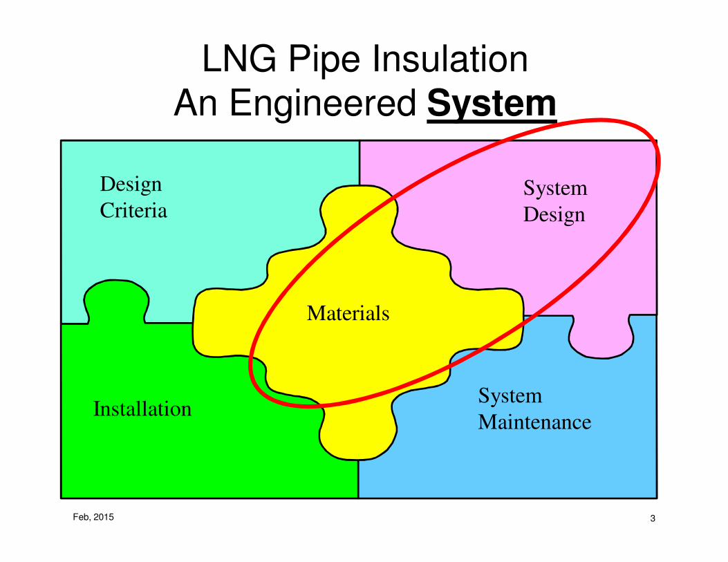
LNG Pipe InsulationAn Engineered System
Materials
Installation
Design
CriteriaSystem
Design
System
Maintenance
Feb, 2015 3

Why LNG Pipe Is
Insulated
• Reasons to insulate– Limit Heat Gain (btu/hr/ft2 or btu/hr/lineal ft)
• 8 btu/hr/ft2 of jacket area “Rule of Thumb” often used
– Condensation Control– Process Control (reduce boil-off gas)
• Insulation system specifications– VERY detailed in LNG piping– Easily can be 100 pages long just for pipe
insulation
Design
Criteria
Feb, 2015 4

System Design
• Based on Analysis of Design Criteria
– Materials of construction• jacketing
• jacket joint sealant
• vapor stops
• elbows/fittings
• pipe coating
• insulation
• insulation joint sealant
• vapor retarder
– Insulation thickness & number of layers–For PIR based LNG systems, double
and triple layering is required– Double layer ≤ 5-6" of insulation
– Triple layer > 5-6" of insulation
System
Design
Feb, 2015 5
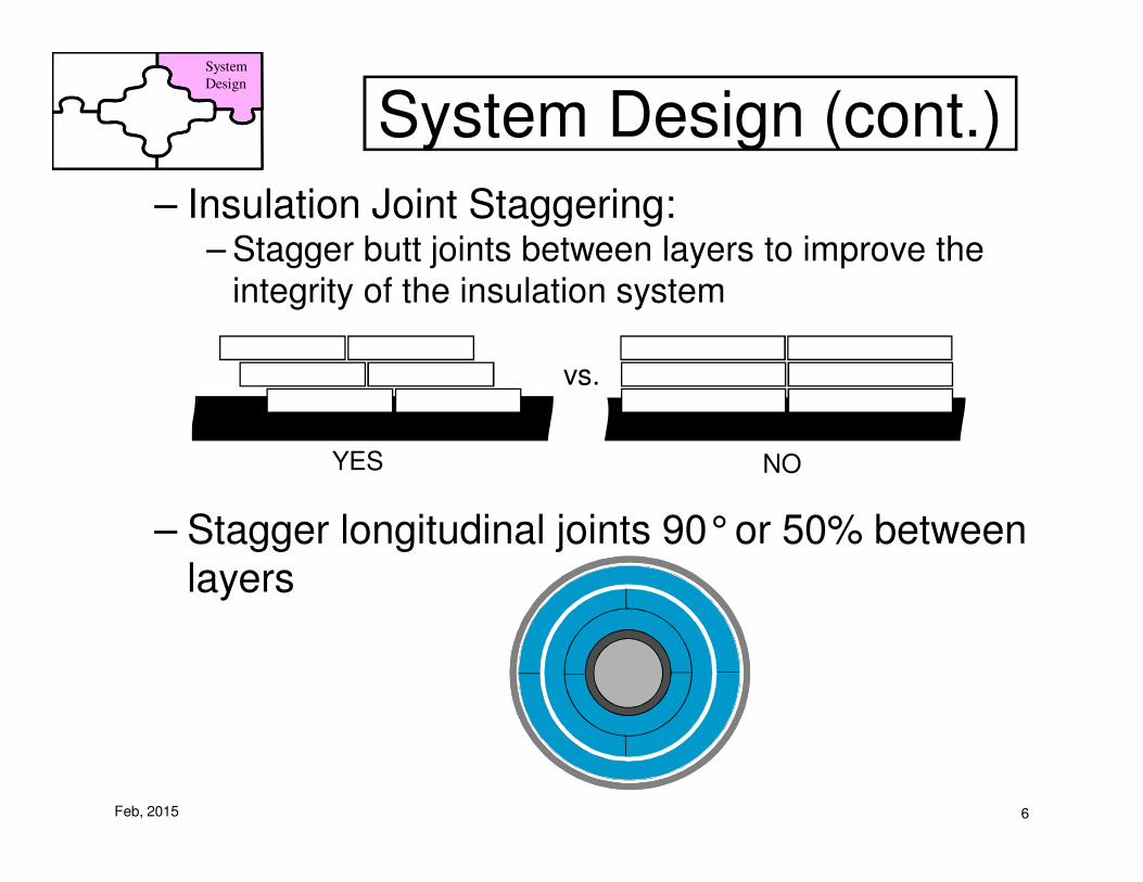
System Design (cont.)System
Design
– Insulation Joint Staggering:– Stagger butt joints between layers to improve the
integrity of the insulation system
– Stagger longitudinal joints 90°or 50% between layers
vs.
YES NO
Feb, 2015 6

System Design (cont.)
• Butt joint staggering
System
Design
Feb, 2015 7

System Design (cont.)
• Longitudinal joint
staggering
– 50% for curved segments
System
Design
Feb, 2015 8

System Design (cont.)
– Joint sealant application method• Thin layer on entire joint face
• Which joints?– No joint sealant on innermost layer
– Sealant on all joints on 2nd and 3rd layer
System
Design
Feb, 2015 9

System Design (cont.)
– Contraction joint design and spacing• The use of contraction joints are required in most PIR
insulation layers on LNG lines
System
Design
Feb, 2015 10

System Design (cont.)
– Vapor retarder installation• Primary and secondary V.R.
• Closure and restraint systems
– Vapor retarder on elbows and fittings• May be different than straights
System
Design
Feb, 2015 11

System Design (cont.)
– Vapor stops - design and locations• Required at some specific places in LNG piping, for example at
valves and flanges
• Also recommended periodically on any long run of LNG pipe
• Many designs are possible. Below is one example
System
Design
Feb, 2015 12
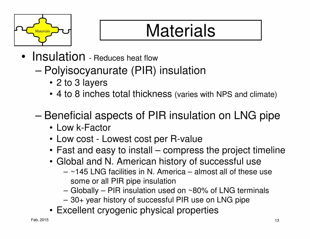
Materials
• Insulation - Reduces heat flow
– Polyisocyanurate (PIR) insulation• 2 to 3 layers
• 4 to 8 inches total thickness (varies with NPS and climate)
– Beneficial aspects of PIR insulation on LNG pipe• Low k-Factor
• Low cost - Lowest cost per R-value
• Fast and easy to install – compress the project timeline
• Global and N. American history of successful use– ~145 LNG facilities in N. America – almost all of these use
some or all PIR pipe insulation
– Globally – PIR insulation used on ~80% of LNG terminals
– 30+ year history of successful PIR use on LNG pipe
• Excellent cryogenic physical properties
Materials
Feb, 2015 13

Materials (cont.)
• Insulation Joint Sealant - Reduces water & vapor movement
through insulation joints
– Not Used on Innermost Layer of a Multi-layer System
– Must be Acceptable at Coldest Temperature Encountered• Usually NOT the same as the service temperature
– Must be applied appropriately• Thin layer to avoid thermal shorts
Materials
Feb, 2015 14

Materials (cont.)
• Vapor Retarder - Severely limit vapor movement toward pipe
– Permeance Must Meet Design Requirements• General guideline in refrigeration is ≤ 0.02 perms
• Better choice for LNG is ≤ 0.01 perms
• Watch for “ideal” vs. “real-world” performance
• Assure all VR joints are properly sealed
– Consider Other Desirable VR Properties• Puncture, Abrasion, & Tear Resistance
• Flame/smoke performance
• Tensile strength
• Cost
Materials
Feb, 2015 15

Materials (cont.)
• Vapor Retarder - Severely limit vapor movement toward pipe
– Primary Vapor Retarder on outside of outer insulation layer
– Secondary Vapor Retarder also critical – Recommendations for LNG
– Avoid aluminum foil based products where the foil is exposed (FSK & ASJ)
Materials
• Primary Vapor Retarder• Rubberized bituminous membranes• Low perm plastic films• Mastic-fabric-mastic
• Secondary Vapor Retarder• Low perm plastic films• Mylar/Aluminum/Mylar
Feb, 2015 16

• Vapor Retarder and Joint Sealant Placement
Two layer system �
Three layer system �
PRIMARYVAPOR RETARDER
OUTER JACKET
JOINT SEALANT
SECONDARYVAPOR RETARDER
PRIMARYVAPOR RETARDER
OUTER JACKET
JOINT SEALANT
SECONDARYVAPOR RETARDER
Note where the joint sealants are used
•No joint sealant on inner layer
Materials Materials (cont.)
JOINT SEALANT
PRIMARYVAPOR RETARDER
OUTER JACKET
SECONDARYVAPOR RETARDER
JOINT SEALANT
PRIMARYVAPOR RETARDER
OUTER JACKET
SECONDARYVAPOR RETARDER
Feb, 2015 17
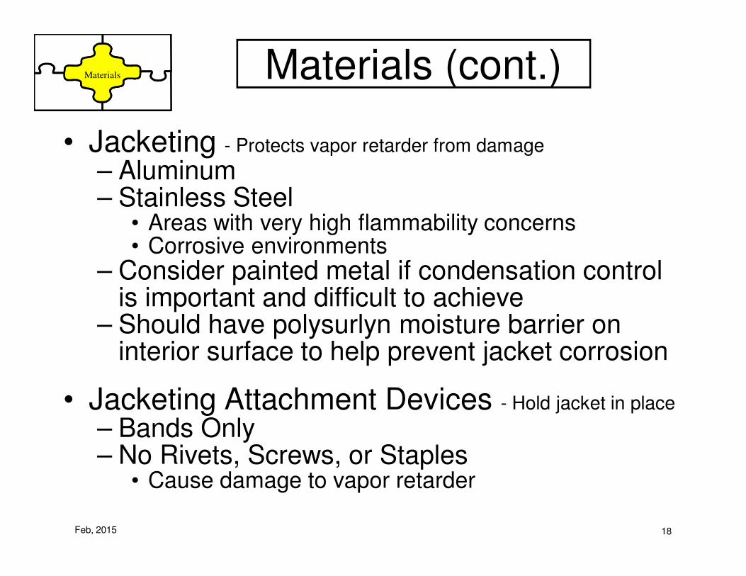
Materials (cont.)
• Jacketing - Protects vapor retarder from damage
– Aluminum– Stainless Steel
• Areas with very high flammability concerns• Corrosive environments
– Consider painted metal if condensation control is important and difficult to achieve
– Should have polysurlyn moisture barrier on interior surface to help prevent jacket corrosion
• Jacketing Attachment Devices - Hold jacket in place
– Bands Only– No Rivets, Screws, or Staples
• Cause damage to vapor retarder
Materials
Feb, 2015 18

Experience With PIR Insulation on LNG Pipe
• 1967 - Earliest example known to this author of PIR on LNG pipe– Small facility in USA – peak shaver or similar– Probably used earlier
• ~140 LNG facilities in N. America– Roughly a dozen import/export terminals– Lots of peak shavers/satellite facilities– More than 70% of these use some or all PIR pipe
insulation– Modern trend in N. America terminals is about 50% use
PIR and 50% use cell glass
• Outside N. America, PIR is clearly the pipe insulation of choice for LNG– Korea, Japan, Indonesia, Middle East, S. America, etc.– PIR pipe insulation used in the majority of cases
(est. >80%)
Feb, 2015 19

Experience With PIR Insulation on LNG Pipe
• 2007 Study examined performance history of
existing PIR insulation systems on LNG pipe– Both import/export terminals and small facilities– Projects both in and outside of N. America– Projects installed 10-40 years earlier– Multiple dozens of projects examined– PIR insulation systems on LNG pipe continued to
perform well as much as 40 years after installation
Feb, 2015 20
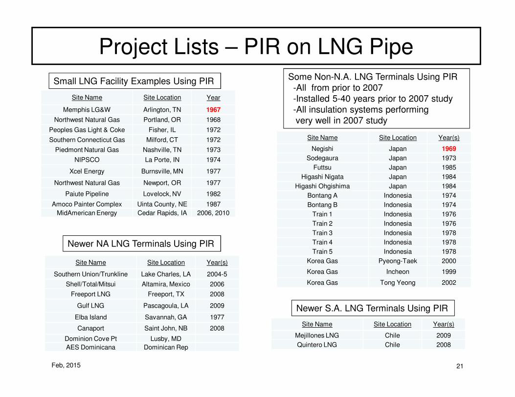
Project Lists – PIR on LNG Pipe
Feb, 2015 21
Site Name Site Location Year
Memphis LG&W Arlington, TN 1967
Northwest Natural Gas Portland, OR 1968
Peoples Gas Light & Coke Fisher, IL 1972
Southern Connecticut Gas Milford, CT 1972
Piedmont Natural Gas Nashville, TN 1973
NIPSCO La Porte, IN 1974
Xcel Energy Burnsville, MN 1977
Northwest Natural Gas Newport, OR 1977
Paiute Pipeline Lovelock, NV 1982
Amoco Painter Complex Uinta County, NE 1987
MidAmerican Energy Cedar Rapids, IA 2006, 2010
Small LNG Facility Examples Using PIR
Newer NA LNG Terminals Using PIR
Site Name Site Location Year(s)
Southern Union/Trunkline Lake Charles, LA 2004-5
Shell/Total/Mitsui Altamira, Mexico 2006
Freeport LNG Freeport, TX 2008
Gulf LNG Pascagoula, LA 2009
Elba Island Savannah, GA 1977
Canaport Saint John, NB 2008
Dominion Cove Pt Lusby, MD
AES Dominicana Dominican Rep
Some Non-N.A. LNG Terminals Using PIR
-All from prior to 2007
-Installed 5-40 years prior to 2007 study
-All insulation systems performing
very well in 2007 study
Site Name Site Location Year(s)
Negishi Japan 1969
Sodegaura Japan 1973
Futtsu Japan 1985
Higashi Nigata Japan 1984
Higashi Ohgishima Japan 1984
Bontang A Indonesia 1974
Bontang B Indonesia 1974
Train 1 Indonesia 1976
Train 2 Indonesia 1976
Train 3 Indonesia 1978
Train 4 Indonesia 1978
Train 5 Indonesia 1978
Korea Gas Pyeong-Taek 2000
Korea Gas Incheon 1999
Korea Gas Tong Yeong 2002
Site Name Site Location Year(s)
Mejillones LNG Chile 2009
Quintero LNG Chile 2008
Newer S.A. LNG Terminals Using PIR
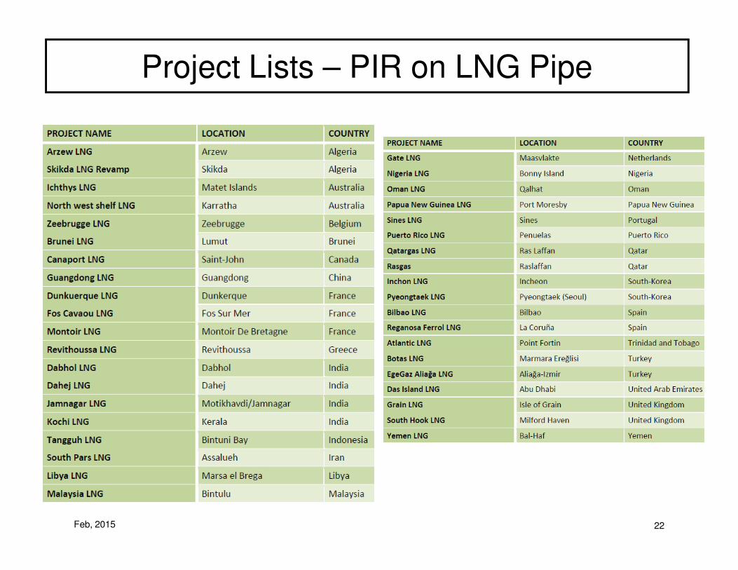
Project Lists – PIR on LNG Pipe
Feb, 2015 22

Project Lists – PIR on LNG Pipe
Feb, 2015 23

Second PIR layer- Joint sealant on all joints- Joints at 6:00 & 12:00- Covered with secondary V.R.
Conclusion• PIR Based LNG Pipe Insulation Systems
– Proven via experience in many projects over long times
– An Engineered Element of the LNG Handling System –Treat it as such
– Typical three-layer PIR insulation based system:
Third PIR layer- Joint sealant on all joints- Joints at 3:00 & 9:00- Covered with primary V.R.
Pipe with first PIR layer- No joint sealant- Joints at 3:00 & 9:00
Protective Metal Jacket w/ PSMB- Aluminum or Stainless- Joint at 3:00 or 9:00- Joint oriented to shed water- Jacketing held on with banding
Feb, 2015 24

PolyisocyanurateBased Insulation Systems for Liquid Natural Gas
(LNG) Piping
Jim YoungFeb. 2015
Will TakeQuestions At End
Feb, 2015 25