Polygon Crawling: Feature-Edge Extraction from a … · Polygon Crawling: Feature-Edge Extraction...
18
Polygon Crawling: Feature-Edge Extraction from a General Polygonal Surface for Mesh Generation Soji Yamakawa and Kenji Shimada The Department of Mechanical Engineering, Carnegie Mellon University 1 [email protected], 2 [email protected] Abstract. This paper describes a method for extracting feature edges of a polygonal sur- face for mesh generation. This method can extract feature edges from a po- lygonal surface typically created by a CAD facet generator in which typical feature edge extraction methods fail due to severe non-uniformity and anisot- ropy. The method is based on the technique called “polygon crawling,” which samples a sequence of points on the polygonal surface by moving a point along the polygonal surface. Extracting appropriate feature edges is important for creating a coarse mesh without yielding self-intersections. Extensive tests have been performed with various CAD-generated facet models, and this technique has shown good performance in extracting feature edges. 1. Introduction This paper describes a method for extracting feature edges of a polygonal sur- face for mesh generation; the input to the proposed method is not limited to a dense uniform triangular mesh. Feature edge extraction methods have been developed for a dense triangular mesh as shown in Fig. 1 (a), which is typi- cally created by a laser range scanner and a uniform mesh as shown in Fig. 1 (b). The proposed method targets a general polygonal surface that includes concave and high aspect-ratio polygons. This method is particularly advanta- geous when feature edges must be extracted from a triangular facet generated by a CAD facet generator, which includes triangles with high aspect ratio. Ex- isting feature edge extraction schemes do not perform well on such triangular facets. This method also tolerates certain discretization noise created by a CAD facet generator. A CAD facet generator often yields concavity where it is convex or convexity where it is concave due to a bug in the facet generator, a bad set of parameters given to the facet generator, or a deficiency of the original CAD model. In this paper, feature edges are defined as a set of edges that must be pre- served, or constrained, to obtain a valid mesh. A mesh is valid if no element 1 2
Transcript of Polygon Crawling: Feature-Edge Extraction from a … · Polygon Crawling: Feature-Edge Extraction...
Polygon Crawling: Feature-Edge Extraction from a General Polygonal Surface for Mesh Generation
Soji Yamakawa and Kenji Shimada
The Department of Mechanical Engineering, Carnegie Mellon University [email protected], [email protected]
Abstract.
This paper describes a method for extracting feature edges of a polygonal sur-face for mesh generation. This method can extract feature edges from a po-lygonal surface typically created by a CAD facet generator in which typical feature edge extraction methods fail due to severe non-uniformity and anisot-ropy. The method is based on the technique called “polygon crawling,” which samples a sequence of points on the polygonal surface by moving a pointalong the polygonal surface. Extracting appropriate feature edges is important for creating a coarse mesh without yielding self-intersections. Extensive tests have been performed with various CAD-generated facet models, and thistechnique has shown good performance in extracting feature edges.
1. Introduction This paper describes a method for extracting feature edges of a polygonal sur-face for mesh generation; the input to the proposed method is not limited to a dense uniform triangular mesh. Feature edge extraction methods have been developed for a dense triangular mesh as shown in Fig. 1 (a), which is typi-cally created by a laser range scanner and a uniform mesh as shown in Fig. 1(b). The proposed method targets a general polygonal surface that includesconcave and high aspect-ratio polygons. This method is particularly advanta-geous when feature edges must be extracted from a triangular facet generatedby a CAD facet generator, which includes triangles with high aspect ratio. Ex-isting feature edge extraction schemes do not perform well on such triangularfacets. This method also tolerates certain discretization noise created by a CAD facet generator. A CAD facet generator often yields concavity where it is convex or convexity where it is concave due to a bug in the facet generator,a bad set of parameters given to the facet generator, or a deficiency of theoriginal CAD model.
In this paper, feature edges are defined as a set of edges that must be pre-served, or constrained, to obtain a valid mesh. A mesh is valid if no element
1 2
258 Soji Yamakawa and Kenji Shimada
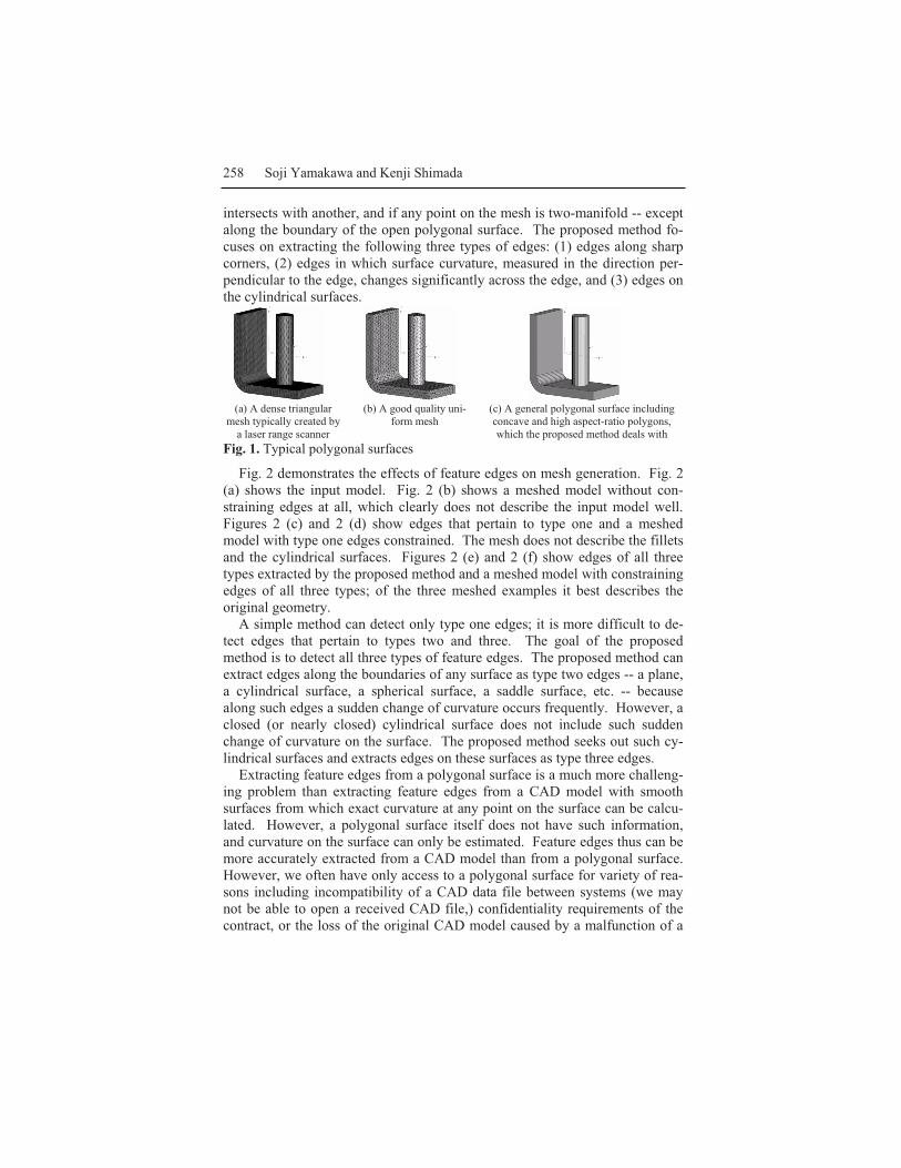
intersects with another, and if any point on the mesh is two-manifold -- except along the boundary of the open polygonal surface. The proposed method fo-cuses on extracting the following three types of edges: (1) edges along sharpcorners, (2) edges in which surface curvature, measured in the direction per-pendicular to the edge, changes significantly across the edge, and (3) edges onthe cylindrical surfaces.
(a) A dense triangularmesh typically created by
a laser range scanner
(b) A good quality uni-form mesh
(c) A general polygonal surface including concave and high aspect-ratio polygons,which the proposed method deals with
Fig. 1. Typical polygonal surfaces
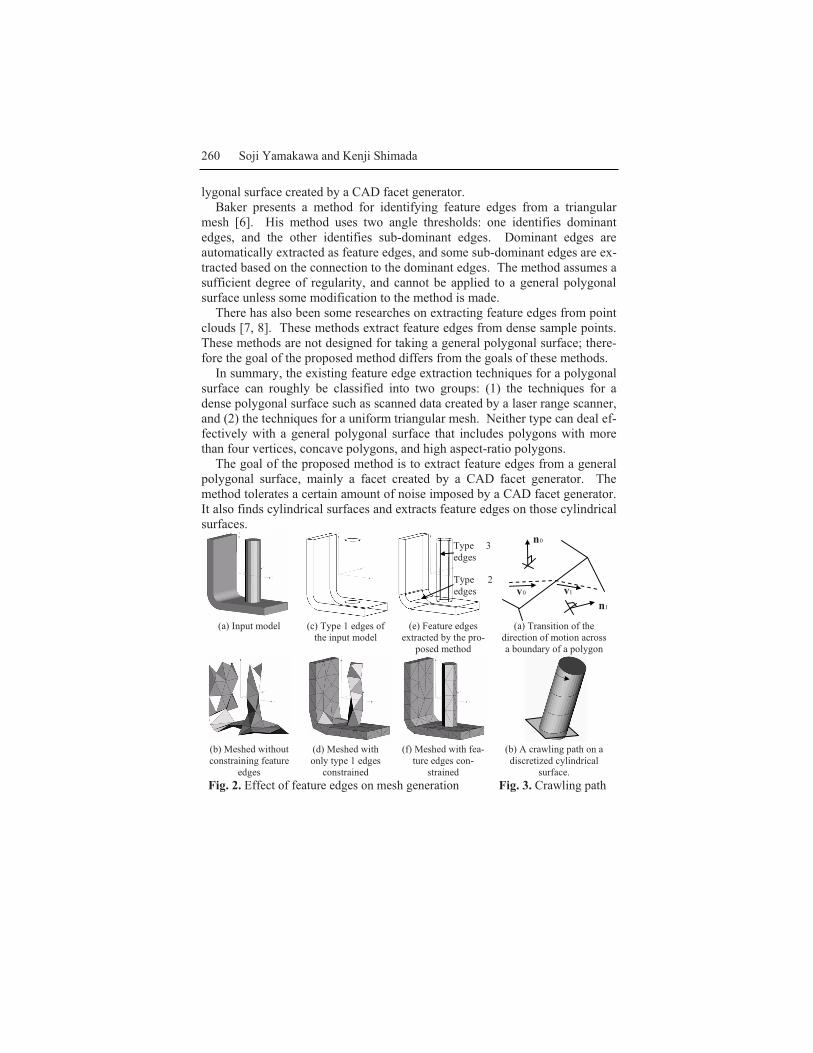
Fig. 2 demonstrates the effects of feature edges on mesh generation. Fig. 2(a) shows the input model. Fig. 2 (b) shows a meshed model without con-straining edges at all, which clearly does not describe the input model well. Figures 2 (c) and 2 (d) show edges that pertain to type one and a meshed model with type one edges constrained. The mesh does not describe the filletsand the cylindrical surfaces. Figures 2 (e) and 2 (f) show edges of all three types extracted by the proposed method and a meshed model with constraining edges of all three types; of the three meshed examples it best describes theoriginal geometry.
A simple method can detect only type one edges; it is more difficult to de-tect edges that pertain to types two and three. The goal of the proposedmethod is to detect all three types of feature edges. The proposed method can extract edges along the boundaries of any surface as type two edges -- a plane, a cylindrical surface, a spherical surface, a saddle surface, etc. -- because along such edges a sudden change of curvature occurs frequently. However, a closed (or nearly closed) cylindrical surface does not include such sudden change of curvature on the surface. The proposed method seeks out such cy-lindrical surfaces and extracts edges on these surfaces as type three edges.
Extracting feature edges from a polygonal surface is a much more challeng-ing problem than extracting feature edges from a CAD model with smoothsurfaces from which exact curvature at any point on the surface can be calcu-lated. However, a polygonal surface itself does not have such information,and curvature on the surface can only be estimated. Feature edges thus can be more accurately extracted from a CAD model than from a polygonal surface.However, we often have only access to a polygonal surface for variety of rea-sons including incompatibility of a CAD data file between systems (we may not be able to open a received CAD file,) confidentiality requirements of thecontract, or the loss of the original CAD model caused by a malfunction of a
Polygon Crawling 259
computer or operator error. In such cases it is necessary to develop a methodfor estimating curvature and extracting feature edges from a polygonal sur-face.
The proposed method uses a procedure called polygon crawling for estimat-ing curvature and finding feature edges. The polygon crawling method sam-ples sequence of points, called a “crawling path,” on the polygonal surface.The curvature of the polygonal surface is estimated by analyzing the crawlingpath. The method locates the feature edges where the estimated curvaturechanges significantly from one side of the edge to the other. The cylindricalsurface in the polygonal surface can be found by (1) finding a principal curva-ture direction at a point on the polygonal surface, and (2) fitting a circle to thecrawling path starting from the point toward the principal curvature direction.
The organization of the paper is as follows. Section 2 reviews previouswork of the feature edge extraction. Section 3 explains the polygon crawlingmethod. Section 4 explains the parameters that control the results of the pro-posed method. Section 5 describes how the curvature is estimated, and Sec-tion 6 presents the algorithm of extracting feature edges based on the curva-ture estimation. Section 7 shows some results, and Section 8 concludes thepaper.
2. Related WorkMangan and Whitaker present a method for partitioning a dense 3D mesh [1]. Their method calculates a curvature (or some other height function) at eachvertex, and merges regions based on the curvature (or the height). Feature edges can be extracted by taking edges between partitions. Their method,however, is not designed for a mesh that includes high aspect ratio triangles.
Nomura and Hamada present a method for extracting feature edges from atriangular mesh [2]. Their method first calculates a measurement called “con-cavity-convexity,” and extracts edges between a convex triangle and a concavetriangle. The method also assumes a dense uniform mesh as input.
Jiao and Heath present a method for extracting feature edges [3, 4]. Theirmethod finds a set of edges that the dihedral angle exceeds the given thresholdcalled θ -strong edges, and takes as a feature edge a θ -strong edge that islikely to form a smooth curve when it is connected to a neighboring θ -strongedge. Their method is designed for a uniform mesh, and more work needs tobe done to extend this method to a general polygonal surface.
Sun et al. present a method for detecting feature edges [5]. This methodcomputes the likelihood of an edge to be a feature edge -- called the “edgestrength,” by taking vote of tensors calculated from the normal vectors of the vertices weighted by the geodesic distance from the edge. Their method is de-signed for segmenting a dense uniform mesh, such as a mesh created by a la-ser range scanner, and more work must be done to extend this method to a po-
260 Soji Yamakawa and Kenji Shimada
lygonal surface created by a CAD facet generator. Baker presents a method for identifying feature edges from a triangular
mesh [6]. His method uses two angle thresholds: one identifies dominant edges, and the other identifies sub-dominant edges. Dominant edges are automatically extracted as feature edges, and some sub-dominant edges are ex-tracted based on the connection to the dominant edges. The method assumes asufficient degree of regularity, and cannot be applied to a general polygonalsurface unless some modification to the method is made.
There has also been some researches on extracting feature edges from point clouds [7, 8]. These methods extract feature edges from dense sample points. These methods are not designed for taking a general polygonal surface; there-fore the goal of the proposed method differs from the goals of these methods.
In summary, the existing feature edge extraction techniques for a polygonal surface can roughly be classified into two groups: (1) the techniques for a dense polygonal surface such as scanned data created by a laser range scanner, and (2) the techniques for a uniform triangular mesh. Neither type can deal ef-fectively with a general polygonal surface that includes polygons with morethan four vertices, concave polygons, and high aspect-ratio polygons.
The goal of the proposed method is to extract feature edges from a general polygonal surface, mainly a facet created by a CAD facet generator. Themethod tolerates a certain amount of noise imposed by a CAD facet generator. It also finds cylindrical surfaces and extracts feature edges on those cylindrical surfaces.
(a) Input model (c) Type 1 edges of the input model
(e) Feature edgesextracted by the pro-
posed method
(a) Transition of the direction of motion across a boundary of a polygon
(b) Meshed withoutconstraining feature
edges
(d) Meshed with only type 1 edges
constrained
(f) Meshed with fea-ture edges con-
strained
(b) A crawling path on adiscretized cylindrical
surface.Fig. 2. Effect of feature edges on mesh generation Fig. 3. Crawling path
Type 2edges
Type 3edges
0n
1n0v 1v
Polygon Crawling 261
3. Polygon Crawling The proposed feature edge detection technique relies on the technique calledpolygon crawling, which samples sequence of points along a path on the po-lygonal surface called a crawling path. A crawling path is analogue to a geo-desic path of a smooth surface. However, a crawling path is a set of line seg-ments as opposed to a smooth geodesic path of a smooth surface.
A crawling path is defined by an initial point on a polygonal surface, aninitial direction, and termination criteria. An initial direction must beperpendicular to the normal of the polygonal surface at the initial point.Termination criteria can be anything; typically it is based on the length and/or the total angular change of the direction.
Assume that a sample point is located at the given initial point and moving toward the initial direction. The sample point maintains the same direction until it reaches the boundary of the polygon – an edge or a vertex. When thesample point moving toward 0v direction hits the boundary and moves out ofthe polygon whose unit normal is 0n , and it moves into a polygon whose unitnormal is 1n , the moving direction changes to 0101 )( vnnRv →= where )( 10 nnR →is a 3x3 affine transformation matrix that rotates 0n into 1n about 10 nn × asshown in Fig. 3 (a). The sample point keeps moving until the terminationcriteria is met. A crawling path is then written as },...,,{ 10 NC ppp= where ip isthe point at which the sample point crosses an edge or a vertex for )1( +i thtime. Fig. 3 (b) shows an example of a crawling path on a discretized cylindrical surface.
We also define a “crawling plane” as 0)()( 00 =×⋅− nvox cp , where x is a pointon the crawling plane, cpo is the initial point of the crawling path, 0v is a unit vector parallel to the initial direction of the crawling path, and 0n is the normal of the polygon on which the initial point is lying. A crawling plane is shown in Fig. 3 (b) by the semi-transparent rectangle.
As can be seen from Fig. 3 (b), a crawling path can move away from thecrawling plane. We define a “twist angle” at each point on a crawling path formeasuring a directional deviation of the crawling direction from the crawlingplane. If the direction of the crawling path is nv ( nv is a unit vector) at point x on the crawling path, the twist angle is defined as )(asin cpntw nv ⋅=θ , where
cpn is the normal of the crawling plane written as )( 00 nvn ×=cp .
4. User-Specified ParametersThe result of the proposed method can be controlled by eight parameters as shown in Table 1. For obtaining the best result, these parameters must be ad-justed for the meshing requirements and the behavior of the CAD facet gen-erator. However, because it is difficult to quantify the behavior of the CAD
262 Soji Yamakawa and Kenji Shimada
facet generator, a good combination of these parameters can only be foundempirically. The experiments performed in this research suggest that the sameset of parameters works well for the polygonal surfaces created by the sameCAD facet generator.
Smaller shallowω , sharpω , twistω , 1γ , and 2γ capture more feature edges, and in-creases the sensitivity to the noise. Parameters 1cylω and 2cylω also control sen-sitivity to noise, and smaller 1cylω and 2cylω capture more cylindrical surfaces,and increases sensitivity to noise. Hence, if the CAD facet generator creates apolygonal surface with little unevenness, these parameters can be smaller, and the method will give satisfactory results. Or if the CAD facet generator cre-ates an uneven (noisy) polygonal surface, these parameters should be in-creased. cylN depends on how smooth a cylindrical surface needs to be when it is meshed. Larger cylN will yield a smoother mesh on a cylindrical surface. However, it may excessively increase the number of elements. A set of pa-rameters that gave a good performance for majority of the test models is pre-sented in Section 7.
Table 1. Input parameters
shallowω If two vectors make an angle less than shallowω , two vectors are con-sidered to be equivalent.
sharpω An angle threshold for finding sharp corners. It is also used for ter-mination condition of the crawling method detailed in Section 5.2.
twistω An angle threshold used for a termination condition of the crawling method detailed in Section 5.2.
1γ , 2γ Two thresholds for finding feature edges in which the curvature changes significantly, detailed in Section 6.2.
1cylω , 2cylω Two angle thresholds for finding cylindrical surfaces, detailed in Section 6.3.
cylN The required number of subdivision around a complete cylinder, de-tailed in Section 6.3.
5. Estimating Curvature by Polygon Crawling The proposed method estimates curvature on the polygonal surface by analyz-ing a crawling path. The goal is to estimate a curvature of the polygonal sur-face at sample point x measured in direction 0v . In the following, a curva-ture estimation scheme of two-dimensional line segments is briefly reviewed,and it is then extended for estimating curvature of a crawling path, which isessentially the curvature estimation of the polygonal surface measured in theinitial crawl direction.
Polygon Crawling 263
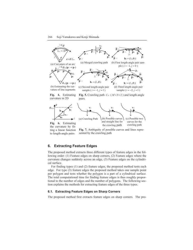
5.1. Curvature Estimation of 2D Line SegmentsThe curvature of a curve is defined as cr/1=κ where cr is the curvature radius.Hence, if two tangential vectors at the two end points of a partial circular arcof length arcl makes angle θ , the curvature of the arc is calculated as
arclr //1 θκ == , because θrlarc = as shown in Fig. 4 (a). Therefore, the curva-ture of a curve can be approximated by the angular change of a tangential vec-tor divided by the arc length required for yielding the change.
Similarly, the curvature of line segments can be estimated by the angularchange of the average tangential vector divided by the length required to yield the change. If 0p , 1p , …, Np are the vertices of line segments, average tan-gential vectors are calculated as: 01010 /)( ppppt −−= at 0p , 11 /)( −− −−= NNNNN pppptat Np , and 1111 /)( −+−+ −−= iiiii ppppt at ip ( )0 Ni<< .
Curvature on line segments between ip and jp ( ji< ) can be estimated as )(/)()( jisegjisegji l pppppp →→=→ θκ , where )( jiseg pp →θ is the angular change of the
average tangential vector between ip and jp , and −
=+ −=→
11)(
j
iKKKjisegl pppp .
For example, when line segments are defined by six points, 0p , 1p , …, and 5p , curvature of the line segments between 1p and 4p is estimated as:
)/()()(3
114141
=+ −→=→
KKKseg pppppp θκ . As can be seen from Fig. 4 (b),
=+ −
3
11
KKK pp
is analog to the arc length of Fig. 4 (a).
5.2. Curvature Estimation of a Crawling Path To extend the 2D curvature estimation scheme to a crawling path, the sign ofthe angular change of the average tangential vector must be taken into account because the curvature must be positive if the polygonal surface is convexalong the crawling path, and negative if it is concave. Let 0p , 1p , …, and Npbe points of a crawling path, ip )0( Ni≤≤ is the projection of ip on the crawling plane, and Nttt ,...,, 10 are average tangential vectors calculated from Nppp ,...,, 10 .The signed angular change of the tangential vector from it to 1+it is calculatedas: )(acos)( 11iiseg ++ ⋅=→ ii ttppθ if 0)()( 1ii00 ≥×⋅× +ttvn , )(acos)( 11iiseg ++ ⋅−=→ ii ttppθ oth-erwise, where 0n is the normal vector of the polygonal surface at the initial point of the crawling path. The angular change of the tangential vector from
it to jt ( ji< ) is calculated as: −
=+→=→
11)()(
j
iKKKsegjiseg pppp θθ . The curvature of
the projected crawling path between ip and jp can be estimated as:)(/)()( jisegjisegjiseg l pppppp →→=→ θκ .
For estimating the curvature of the polygonal surface at x in 0v direction,the following two issues still need to be considered: (1) termination criteria forsampling a crawling path, and (2) choice of i and j .
264 Soji Yamakawa and Kenji Shimada
The proposed curvature estimation method uses three user-specified pa-rameters, sharp angle threshold – sharpω , twist angle threshold – twistω , and shal-low angle threshold – shallowω for defining the termination criteria. The pro-posed method samples two crawling paths },...,,{ 100 NC aaa= , and
},...,,{ 101 MC bbb= . Projection of 0C on the crawling plane is },...,,{ 100 NC aaa= ,and 1C },...,,{ 101 MC bbb= . The initial point of both 0C and 1C are x , and the initial crawling direction of 0C is 0v and of 1C is 0v− . For both directions, the points are sampled until: (1) total angular change of the average tangential vector on the crawling plane exceeds sharpω , i.e., both )( 0 Nseg aa →θ and
)( 0 Mseg bb →θ do not exceed sharpω , (2) angular change of the normal vectors of polygons in one step of crawling exceeds sharpω , or (3) twist angle exceeds
twistω .The two crawling paths are then merged into a crawling path:
},...,,{ )1( NMMallC ppp −+−= },...,,,...,,{ 001 NMM aabbb −= . Projection of allC on the crawling plane is },...,,{ )1( NMMallC ppp −+−= . Fig. 5 (a) shows an example of a merged crawling path.
From the merged crawling path, allC , )( jiseg pp →κ can be computed for anyi and j that satisfy ji < , iM ≤+− )1( , 1−≤Ni , jM ≤− , and Nj≤ , and the cur-vature of the polygonal surface at x in 0v direction is found by choosing ap-propriate i and j . However, it is very difficult to automatically choose ap-propriate i and j . Instead of choosing only one set of i and j , the proposed method estimates the curvature from some pairs of )( jisegl pp → and
)( jiseg pp →θ , or length-angle pairs, written as ),( kkk l θ=h , by the following algo-rithm.
Let 0=kLet i be the largest integer that satisfies shallowiseg ωθ ≥→ )( 0pp and 0<i .
(If none satisfies, )1( +−= Mi )Let j be the smallest integer that satisfies shallowjseg ωθ ≥→− )( 1 pp and j≤0 .
(If none satisfies, Nj= )Do:
Set ))(),((),( jisegjisegkkk ll pppph →→== θθFind the next value of j , 'j , which satisfies:
shallowjjseg ωθ ≥→ )( 'pp , Nj≤ , and 'jj< . (If none satisfies, Nj =' )Find the next value of i , 'i , which satisfies:
shallowiiseg ωθ ≥→ )( ' pp , iM <+− )1( , and ii <' . (If none satisfies, )1(' +−= Mi )If )()( 10 jsegiseg ll pppp →<→ − replace i with 'i , otherwise replace j with 'j .Increment k .
Until one of sharpjiseg ωθ >→ )( pp or ( )1( +−= Mi and Nj= ) is satisfied.This algorithm updates i and j so that the growth of )( 0pp →isegl and
)( 1 jsegl pp →− are balanced. Fig. 5 (b), (c), and (d) show examples of length-
Polygon Crawling 265
angle pairs. Finally, the curvature is estimated from the length-angle plot. On length-
angle plot with length as the lateral axis and angle as the vertical axis, theslope of a function )(lf=θ describes the curvature. Hence, the curvature canbe estimated by the least-square fitting of function lestκθ = to kh as shown inFig. 6; and estκ is written as: =
k kkkkest ll 2
0 /),( θκ vx , which gives an estimated cur-
vature at x measured in 0v direction.
5.3. Reliability of the Curvature Estimation for a Crawling PathA reliability measure of the estimated curvature must be taken into account toavoid excessive extraction of feature edges. If the estimated curvature is sub-ject to considerable error, it makes a sudden change of the estimated curvatureacross an edge, and the proposed method may falsely consider some edges asfeature edges.
The curvature estimation scheme explained in Sections 5.1 and 5.2 becomesinaccurate where the curvature changes from negative to positive. For exam-ple, for the crawling path shown in Fig. 7 (a), the exact curvature could bezero because the sample point is on a straight line connecting two curves asshown in Fig. 7 (b), or it could be non-zero because the sample point is on oneof the two curves represented by the sampled crawling path.
The proposed method tests the reliability of the curvature estimation as fol-lows. Let I and J be smallest i and largest j used for sampling length-angle pairs. The curvature estimation is considered to be unreliable if all threeconditions of the following are satisfied: (1) 0)()( 10 <→→ − JsegIseg pppp θθ , (2)
shallowJseg ωθ >→ )( 0 pp , and (3) shallowiseg ωθ >→ )( 0pp . These conditions checkwhether the crawling path bends considerably to both positive and negativecurvature directions. If at least one of the three conditions is not satisfied, thecurvature estimation is considered to be reliable.
5.4. Finding Principal CurvatureThe principal curvature at a point on the polygonal surface can be found bynumerically maximizing the absolute value of the curvature estimated by thescheme explained in Section 5.2. Let x be a point on the polygonal surface,and n be the normal of the polygonal surface at x . i is an arbitrary unit vec-tor that satisfies 0=⋅ in , and inj ×= . Any unit vector parallel to the polygoncan be described as φφφ sincos)( jiv += . The problem of finding the principal curvature at x thus becomes a one-dimensional optimization problem: findingφ that maximizes ))(,( φκ vxest . A conventional numerical optimization scheme such as bi-section search, Newton’s method, or Powell’s method, can solve this problem.
266 Soji Yamakawa and Kenji Shimada
(a) Curvature of an arc
(b) Estimating the cur-vature of line segments
Fig. 4. Estimating curvature in 2D
Fig. 5. Crawling path allC ( 2==NM ) and length-anglepairs.
Fig. 6. Estimatingthe curvature by fit-ting a linear functionto length-angle pairs
Fig. 7. Ambiguity of possible curves and lines repre-sented by the crawling path
6. Extracting Feature EdgesThe proposed method extracts three different types of feature edges in the fol-lowing order: (1) Feature edges on sharp corners, (2) Feature edges where thecurvature changes suddenly across an edge, (3) Feature edges on the cylindri-cal surface.
For finding types (1) and (2) feature edges, the proposed method tests each edge. For type (3) feature edges the proposed method takes one sample point per polygon and tests whether the polygon is a part of a cylindrical surface. The total computational time for finding feature edges is thus roughly propor-tional to the number of edges and the number of polygons. The following sec-tion explains the methods for extracting feature edges of the three types.
6.1. Extracting Feature Edges on Sharp Corners The proposed method first extracts feature edges on sharp corners. The pro-
sharpθθ
lestκ
0h
1h 2h
x
0v
x
0v 0v
x(a) Crawling Path (b) Possible curves
and straight line for the crawling path
(c) Possible two curves for the crawling path
0p1p
2p
1−p2−p
3−p1l
1θ
),( 111 θl=h3−p
0p1p
2p
1−p2−p
2l
2θ
),( 222 θl=h
)( 41 pp →segθ
0p
1p 2p 3p 4p
5p
1t
4t
)( 41 pp →segθ
2p
x
0v
0p1p1−p
2−p
3−p
0p1p
2p
1−p2−p
3−p0l
0θ
),( 000 θl=hr
θrlarc =
θ
θ
(a) Merged crawling path (b) First length-angle pair sam-ple ( 0,1 =−= ji )
(c) Second length-angle pair sample ( 1,1 =−= ji )
(d) Third length-angle pair sample ( 1,2 =−= ji )
arcl/θκ =
Polygon Crawling 267
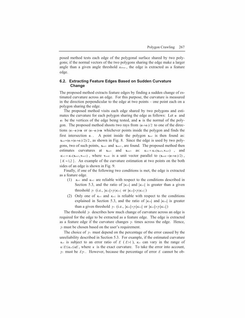
posed method tests each edge of the polygonal surface shared by two poly-gons; if the normal vectors of the two polygons sharing the edge make a largerangle than a given angle threshold sharpω , the edge is extracted as a feature edge.
6.2. Extracting Feature Edges Based on Sudden CurvatureChange
The proposed method extracts feature edges by finding a sudden change of es-timated curvature across an edge. For this purpose, the curvature is measured in the direction perpendicular to the edge at two points – one point each on a polygon sharing the edge.
The proposed method visits each edge shared by two polygons and esti-mates the curvature for each polygon sharing the edge as follows: Let 1e and
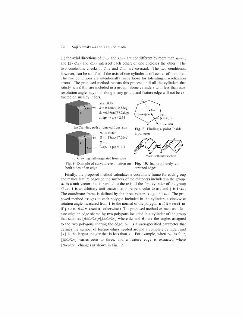
2e be the vertices of the edge being tested, and n is the normal of the poly-gon. The proposed method shoots two rays from 2/)( 21 ee + to one of the direc-tions nee ×− )( 12 or nee ×− )( 21 whichever points inside the polygon and finds the first intersection xe . A point inside the polygon midx is then found as:
2/)2/)(( 21 eeex ++= xmid , as shown in Fig. 8. Since the edge is used by two poly-gons, two of such points, 1midx and 2midx , are found. The proposed method thenestimates curvatures at 1midx and 2midx as: ),( 111 midmidestest vxκκ = , and
),( 222 midmidestest vxκκ = , where midKv is a unit vector parallel to )2/)(( 21 eex +−midK ,{ 2,1=K }. An example of the curvature estimation at two points on the both sides of an edge is shown in Fig. 9.
Finally, if one of the following two conditions is met, the edge is extracted as a feature edge.
(1) 1estκ and 2estκ are reliable with respect to the conditions described inSection 5.3, and the ratio of 1estκ and 2estκ is greater than a giventhreshold 1γ (i.e., 211 estest κγκ > or 112 estest κγκ > )
(2) Only one of 1estκ and 2estκ is reliable with respect to the conditions explained in Section 5.3, and the ratio of 1estκ and 2estκ is greaterthan a given threshold 2γ (i.e., 221 estest κγκ > or 122 estest κγκ > )
The threshold 1γ describes how much change of curvature across an edge isrequired for the edge to be extracted as a feature edge. The edge is extractedas a feature edge if the curvature changes 1γ times across the edge. Hence,
1γ must be chosen based on the user’s requirement.The choice of 2γ must depend on the percentage of the error caused by the
unreliability described in Section 5.3. For example, if the estimated curvatureestκ is subject to an error ratio of E ( 1>E ), estκ can vary in the range of
EE est κκκ ≤≤/ , where κ is the exact curvature. To take the error into account,2γ must be 1γE . However, because the percentage of error E cannot be ob-
268 Soji Yamakawa and Kenji Shimada
tained, 2γ can only be found empirically.
6.3. Extracting Feature Edges on the Cylindrical Surfaces The third procedure in the proposed method extracts feature edges on the cy-lindrical surfaces. It is desirable to constrain four to six edges on the cylindri-cal surface that are parallel to the axis of the cylinder for the meshing as shown in Fig. 2.
It is also important to constrain edges on the co-axial cylindrical surfaces consistently so that meshing does not produce self-intersections. For example, if two co-axial cylindrical surfaces have constrained edges as shown by thick lines in Fig. 10, meshing produces self-intersections when large elements needto be created for reducing the number of elements. Hence, the proposedmethod needs to find cylindrical surfaces from the polygonal surface, and ex-tract feature edges on them consistently so that the chance of yielding suchself-intersections is minimized.
If some polygons represent a complete cylinder (a cylinder whose cross section is a complete circle,) the cylinder can be found by fitting a circle to a crawling path in the principal curvature direction and checking the fitness of the circle to the crawling path. However, it is difficult to identify some poly-gons representing a partial cylinder (a cylinder whose cross section makes apartial circle) because such polygons can also be interpreted as a part of a non-cylindrical surface.
For this reason, a heuristic approach is used for finding partial cylinders. Often a complete cylinder is co-axial to a partial cylinder; when the proposed method finds some polygons that potentially represent a partial cylinder, those polygons are considered to be a part of a cylindrical surface if a complete cyl-inder co-axial to the partial cylinder is located close to the partial cylinder.
The proposed method uses two angle thresholds – 1cylω and 2cylω ( 21 cylcyl ωω < )– to find cylindrical surfaces. When the proposed method locates a set of polygons that may represent a cylindrical surface, it calculates the angle of arc of the cross section of the potential cylindrical surface, denoted as cylθ . Thesurface represented by the polygons is considered to be a complete cylinder if
cylcyl θω ≤2 . If 21 cylcylcyl ωθω <≤ , the surface represented by the polygons is consid-ered to be a partial cylinder if a co-axial complete cylinder is found. The sur-face is not considered to be a part of a cylindrical surface if 1cylcyl ωθ < . Since
cylθ is calculated by taking an angle of revolution made by a crawling patharound the surface, we call cylθ a “revolution angle” of the cylinder.
After locating cylindrical surfaces represented by sets of polygons the pro-posed method makes groups of cylindrical surfaces based on the proximity and axial directions of the cylinders. A coordinate frame is assigned to each group, and feature edges are extracted on the cylindrical surfaces based on thecoordinate frame. Details of the algorithm are described below.
Polygon Crawling 269
The proposed method calculates a principal curvature 1κ and the principal curvature direction 1κv at x by the method described in Section 5.4 where xis a point on the polygonal surface. The method then finds two crawling pathsstarting from x to the directions 1κv± until: (1) total angular change of the av-erage tangential vector exceeds 180 degrees, (2) angular change of the normal vectors of polygons in one step of crawling exceeds sharpω , or (3) twist angle exceeds twistω .
The two crawling paths described as },...,,{ 10 Naaa and },...,,{ 10 Mbbb aremerged into a crawling path: },...,,{ 1 NMMcylC ppp −−−= },...,,,,...,,{ 1001 NMM aaabbb −= .
The revolution angle cylθ is calculated from cylC as: )( 1 NMsegcyl pp →= −−θθ ,which is the total angular change of the tangential vector of the crawling pathfrom 1−−Mp to Np . If the crawling path is on a complete cylindrical surface and makes a complete revolution around the cylinder, cylθ is 360 degrees. Ifthe crawling path is on a partial cylindrical surface, cylθ is less than 360 de-grees.
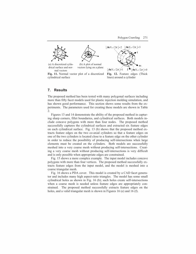
If the crawling path is on a cylindrical surface, the plot of normal vectors lies on a plane, and the normal of the plane is parallel to the axial direction asshown in Fig. 11. The proposed method fits a plane to the normal vectors ofthe polygons that the crawling path passes by the least-square method. Theplane is denoted as nP , and the axial direction is denoted as a .
The points of the crawling path are then projected on nP , and a circle that fits to the projected points is calculated by the least-square method [9, 10]. The center of the circle is o , and the diameter is R . To test the fitness of thecircle to the projected points, the proposed method calculates the maximum and the minimum distances from a projected point to the center of the circle,
maxR and minR .Finally, the proposed method considers that the polygons passed by the
crawling path are part of a cylindrical surface if the following three conditions are satisfied: (1) cylcyl θω ≤1 , (2) 05.1/95.0 max ≤≤ RR , and (3) 05.1/95.0 min ≤≤ RR .
The proposed method tests the above conditions at a sample point per poly-gon and makes a list of detected cylindrical surfaces. If the polygon is con-vex, the sample point for the polygon is the center of the polygon. If the poly-gon is concave, the proposed method picks randomly a point inside thepolygon.
Groups of cylindrical surfaces are then made by the following algorithm.Let Ncylcylcyl CCC ,2,1, ,...,, be the detected cylinders sorted in the descending orderof the revolution angle, and kcyl ,θ be the revolution angle of kcylC , ( Nk ≤≤1 );
jcylicyl ,, θθ ≥ ( ji< ). Assume that IcylC , is the first cylinder that is not yet in anygroup and satisfies Icylcyl ,2 θω ≤ . The proposed method makes a new group ofcylindrical surfaces, KcylG , ( K th group), that initially includes only IcylC , . It then compares IcylC , with JcylC , where NJI ≤≤+1 , and JcylC , is added to KcylG , if
270 Soji Yamakawa and Kenji Shimada
(1) the axial directions of IcylC , and JcylC , are not different by more than shallowω ,and (2) IcylC , and JcylC , intersect each other, or one encloses the other. The two conditions checks if IcylC , and JcylC , are co-axial. The two conditions, however, can be satisfied if the axis of one cylinder is off center of the other.The two conditions are intentionally made loose for tolerating discretization errors. The proposed method repeats this process until all the cylinders that satisfy Icylcyl ,2 θω ≤ are included in a group. Some cylinders with less than 2cylωrevolution angle may not belong to any group, and feature edge will not be ex-tracted on such cylinders.
Fig. 8. Finding a point Insidea polygon
Fig. 9. Example of curvature estimation onboth sides of an edge
Fig. 10. Inappropriately con-strained edges
Finally, the proposed method calculates a coordinate frame for each group and makes feature edges on the surfaces of the cylinders included in the group.
Ka is a unit vector that is parallel to the axis of the first cylinder of the group KcylG , , i is an arbitrary unit vector that is perpendicular to Ka , and j is Kai × .
The coordinate frame is defined by the three vectors i , j , and Ka . The pro-posed method assigns to each polygon included in the cylinders a clockwise rotation angle measured from i to the normal of the polygon n , ( )( niacosn ⋅=θif 0≥⋅nj , )(2 niacosn ⋅−= πθ otherwise.) The proposed method extracts as a fea-ture edge an edge shared by two polygons included in a cylinder of the group that satisfies πθπθ 2/2/ 21 cylcyl NN nn ≠ where 1nθ and 2nθ are the angles assignedto the two polygons sharing the edge, cylN is a user-specified parameter thatdefines the number of feature edges needed around a complete cylinder, and
x is the largest integer that is less than x . For example, when cylN is four, πθ 2/cylNn varies zero to three, and a feature edge is extracted whereπθ 2/cylNn changes as shown in Fig. 12.
1e2e1midx
2midx1e
2e
1e
2e
nee ×− )( 12
nee ×− )( 21
xe
midx
2/)( 12 ee +
49.01 =estκdeg)3.10(rad18.0=Iθdeg)2.56(rad98.0=Jθ
34.2)( =→ JIsegl pp
069.02 =estκg)rad(67.5de18.1=Iθ
0=Jθ3.10)( =→ JIsegl pp
(a) Crawling path originated from 1midx
(b) Crawling path originated from 2midxYield self-intersection
Polygon Crawling 271
(a) A discretized cylin-drical surface and nor-
mal vectors
(b) A plot of normal vectors lying on a plane
Fig. 11. Normal vector plot of a discretizedcylindrical surface
Fig. 12. Feature edges (Thicklines) around a cylinder
7. ResultsThe proposed method has been tested with many polygonal surfaces includingmore than fifty facet models used for plastic injection molding simulation, andhas shown good performance. This section shows some results from the ex-periments. The parameters used for creating these models are shown in Table2.
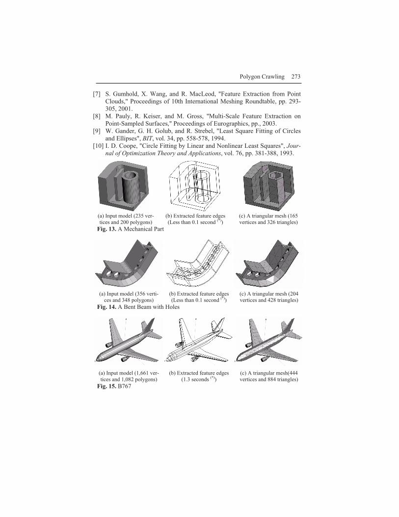
Figures 13 and 14 demonstrate the ability of the proposed method in captur-ing sharp corners, fillet boundaries, and cylindrical surfaces. Both models in-clude concave polygons with more than four nodes. The proposed methodsuccessfully captures the cylindrical surfaces and extracted six feature edgeson each cylindrical surface. Fig. 13 (b) shows that the proposed method ex-tracts feature edges on the two co-axial cylinders so that a feature edges on one of the two cylinders is located close to a feature edge on the other cylinderin order to reduce the possibility of producing self-intersections when largeelements must be created on the cylinders. Both models are successfullymeshed into a very coarse mesh without producing self-intersections. Creat-ing a very coarse mesh without producing self-intersections is very difficult and is only possible when appropriate edges are constrained.
Fig. 15 shows a more complex example. The input model includes concavepolygons with more than four vertices. The proposed method successfully ex-tracts feature edges from the input model, and the model is meshed into acoarse triangular mesh.
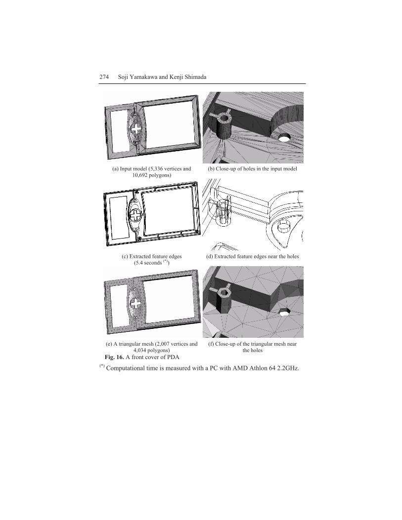
Fig. 16 shows a PDA cover. This model is created by a CAD facet genera-tor and includes many high aspect-ratio triangles. The model has some small cylindrical holes as shown in Fig. 16 (b); such holes create self-intersectionswhen a coarse mesh is needed unless feature edges are appropriately con-strained. The proposed method successfully extracts feature edges on theholes, and a valid triangular mesh is shown in Figures 16 (e) and 16 (f).
Ka
i
j 02/ =πθ cylNn12/ =πθ cylNn
22/ =πθ cylNn 32/ =πθ cylNn
272 Soji Yamakawa and Kenji Shimada
Table 2. Parameters used for creating examples
shallowω 5 degrees twistω 45 degrees 2γ 10 1cylω 45 degrees sharpω 45 degrees 1γ 2 cylN 6 2cylω 270 degrees
8. Discussions and Conclusions The proposed method extracts feature edges from a general polygonal surface. The method extracts (1) edges on sharp corners, (2) edges where the curvaturechanges significantly across the edge, and (3) edges on the cylindrical sur-faces. Such feature edges must be constrained for meshing, or some geomet-ric features will be lost unless sufficiently small elements are used. Themethod has been tested with many polygonal surfaces and has shown a goodperformance on the test models.
The method helps create a coarse mesh without producing self-intersections. However, the method does not necessarily help create good quality elements. For creating a valid and good quality mesh, the proposed method must be used together with an appropriate element sizing function.
The method captures cylindrical surfaces and extracts edges on such cylin-drical surfaces. However, the method does not capture when the cross-section is an ellipse, and/or the surface is significantly tapered. Capturing such ellip-tic cylinders and conic surfaces is a topic for future research.
References[1] A. P. Mangan and R. T. Whitaker, "Partitioning 3D Surface Meshes Using
Watershed Segmentation", IEEE Transactions on Visualization and Com-puter Graphics, vol. 5, pp. 308-321, 1999.
[2] M. Nomura and N. Hamada, "Feature Edge Extraction from 3D TriangularMeshes Using a Thinning Algorithm," Proceedings of SPIE - Vision Ge-ometry X, pp. 34-41, 2001.
[3] X. Jiao and M. T. Heath, "Feature Detection for Surface Meshes," Proceed-ings of 8th International Conference on Numerical Grid Generation inComputational Field Simulations, pp. 705-714, 2002.
[4] X. Jiao and M. T. Heath, "Overlaying Surface Meshes, Part II: TopologyPreservation and Feature Detection", International Journal on Computa-tional Geometry and Applications, vol. 14, pp. 403-419, 2004.
[5] Y. Sun, D. L. Page, J. K. Paik, A. Koschan, and M. A. Abidi, "TriangleMesh-Based Edge Detection and Its Application to Surface Segmentation and Adaptive Surface Smoothing," Proceedings of International Confer-ence on Image Processing, pp. 825-828, 2002.
[6] T. J. Baker, "Identification and Preservation of Surface Features," Proceed-ings of 13th International Meshing Roundtable, pp. 299-309, 2004.
Polygon Crawling 273
[7] S. Gumhold, X. Wang, and R. MacLeod, "Feature Extraction from PointClouds," Proceedings of 10th International Meshing Roundtable, pp. 293-305, 2001.
[8] M. Pauly, R. Keiser, and M. Gross, "Multi-Scale Feature Extraction onPoint-Sampled Surfaces," Proceedings of Eurographics, pp., 2003.
[9] W. Gander, G. H. Golub, and R. Strebel, "Least Square Fitting of Circlesand Ellipses", BIT, vol. 34, pp. 558-578, 1994.
[10] I. D. Coope, "Circle Fitting by Linear and Nonlinear Least Squares", Jour-nal of Optimization Theory and Applications, vol. 76, pp. 381-388, 1993.
(a) Input model (235 ver-tices and 200 polygons)
(b) Extracted feature edges (Less than 0.1 second (*))
(c) A triangular mesh (165vertices and 326 triangles)
Fig. 13. A Mechanical Part
(a) Input model (356 verti-ces and 348 polygons)
(b) Extracted feature edges(Less than 0.1 second (*))
(c) A triangular mesh (204vertices and 428 triangles)
Fig. 14. A Bent Beam with Holes
(a) Input model (1,661 ver-tices and 1,082 polygons)
(b) Extracted feature edges(1.3 seconds (*))
(c) A triangular mesh(444vertices and 884 triangles)
Fig. 15. B767
274 Soji Yamakawa and Kenji Shimada
(a) Input model (5,336 vertices and10,692 polygons)
(b) Close-up of holes in the input model
(c) Extracted feature edges(5.4 seconds (*))
(d) Extracted feature edges near the holes
(e) A triangular mesh (2,007 vertices and4,034 polygons)
(f) Close-up of the triangular mesh near the holes
Fig. 16. A front cover of PDA(*) Computational time is measured with a PC with AMD Athlon 64 2.2GHz.