Polycom IP Ceiling Microphone Array Setup Sheet · Polycom® IP Ceiling Microphone Array SETUP...
7
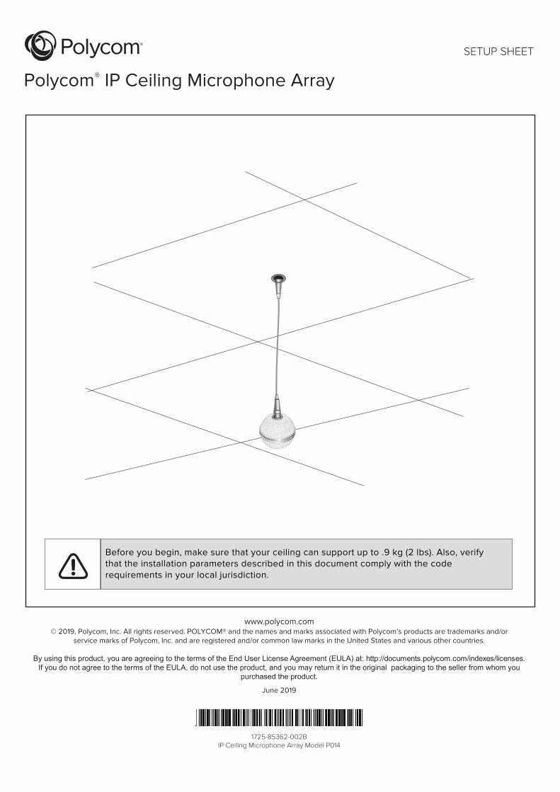
www.polycom.com © 2019, Polycom, Inc. All rights reserved. POLYCOM® and the names and marks associated with Polycom’s products are trademarks and/or service marks of Polycom, Inc. and are registered and/or common law marks in the United States and various other countries. By using this product, you are agreeing to the terms of the End User License Agreement (EULA) at: http://documents.polycom.com/indexes/licenses. If you do not agree to the terms of the EULA, do not use the product, and you may return it in the original packaging to the seller from whom you purchased the product. June 2019 Polycom ® IP Ceiling Microphone Array SETUP SHEET Before you begin, make sure that your ceiling can support up to .9 kg (2 lbs). Also, verify that the installation parameters described in this document comply with the code requirements in your local jurisdiction. 1725-85362-002B IP Ceiling Microphone Array Model P014
Transcript of Polycom IP Ceiling Microphone Array Setup Sheet · Polycom® IP Ceiling Microphone Array SETUP...
www.polycom.com© 2019, Polycom, Inc. All rights reserved. POLYCOM® and the names and marks associated with Polycom’s products are trademarks and/or
service marks of Polycom, Inc. and are registered and/or common law marks in the United States and various other countries.
By using this product, you are agreeing to the terms of the End User License Agreement (EULA) at: http://documents.polycom.com/indexes/licenses.If you do not agree to the terms of the EULA, do not use the product, and you may return it in the original packaging to the seller from whom you
purchased the product.
June 2019
Polycom® IP Ceiling Microphone Array
SETUP SHEET
Before you begin, make sure that your ceiling can support up to .9 kg (2 lbs). Also, verify that the installation parameters described in this document comply with the coderequirements in your local jurisdiction.
1725-85362-002BIP Ceiling Microphone Array Model P014

2 Polycom IP Ceiling Microphone Array Setup Sheet
Polycom IP Ceiling Microphone Array
.6 m (2 ft)2457-85785-024
2.1 m (7 ft)non-plenum straight-through (Use between wall plate and codec only. Donot use for any other application.)2457-17977-007
15.2 m (50 ft)shielded plenum crossover, RJ-45(Use between electronics enclosure andcodec and between electronics enclosureand wall plate.)2457-85361-001
If you are creating your own RJ-45 cables, referto the Polycom RealPresence Group SeriesIntegrator Reference Guide at http://support.polycom.com. Ensure that the cables meet all local building code regulations.
1
Verify that the number of pins on thecable connector matches the numberof pins on the connector on theelectronics enclosure.
If you do not have a suspended ceiling in yourroom, continue with Step 13 on page 5.
For suspended ceilings
2
If height adjustments are required for themicrophone ball, clip the cable clip onto thecable. When you later place the electronicsenclosure on the ceiling tile, you can rest theclip above the hole in the ceiling tile and adjustthe length of the cable as needed.
Polycom IP Ceiling Microphone Array Setup Sheet 3
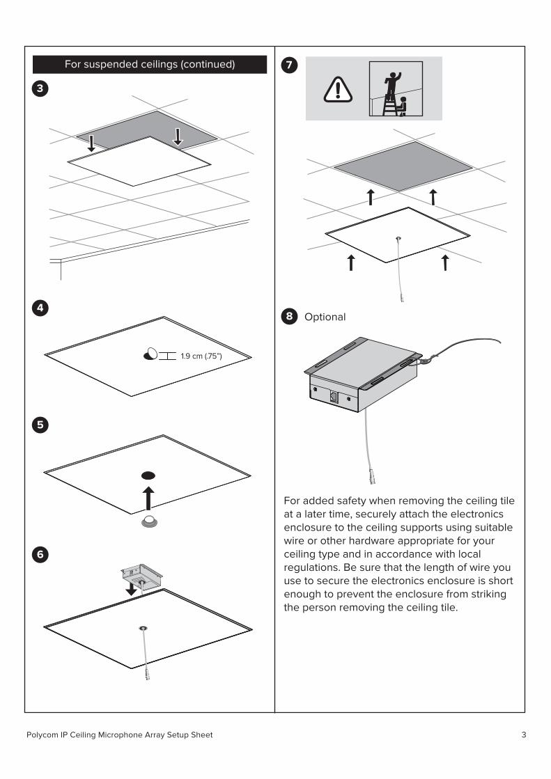
For suspended ceilings (continued)
3
7
8 Optional
For added safety when removing the ceiling tileat a later time, securely attach the electronics enclosure to the ceiling supports using suitable wire or other hardware appropriate for your ceiling type and in accordance with local regulations. Be sure that the length of wire you use to secure the electronics enclosure is short enough to prevent the enclosure from striking the person removing the ceiling tile.
4
1.9 cm (.75”)
5
6
Polycom IP Ceiling Microphone Array Setup Sheet 4
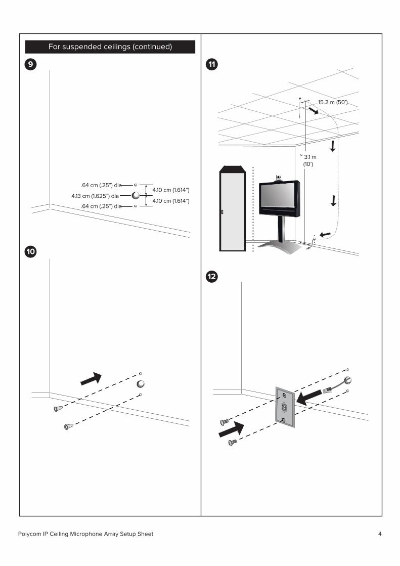
For suspended ceilings (continued)
9
4.13 cm (1.625”) dia
.64 cm (.25”) dia 4.10 cm (1.614”)
4.10 cm (1.614”) .64 cm (.25”) dia
10
11
12
15.2 m (50’)
~ 3.1 m(10’)
SoundStructure C16TM

Polycom IP Ceiling Microphone Array Setup Sheet 5
For ceilings that are not suspended
13
1415.2 m (50’)
~ 3.1 m(10’)
SoundStructure C16TM
For all ceilings
15
16
Point the dot (located on the band around themiddle of the microphone ball) toward the maindisplay.
To attach the electronics enclosure, use suitable hardware for your ceiling type. Polycom recommends using four screws and bolts at least 3mm in diameter and at least 25mm in length to mount the electronics enclosure to a solid surface. If the mounting surface is not solid, use an alternative fixing method to ensure that the mounted device can withstand a pull force of 50N without detaching.
Align the enclosure so that when the IP ceiling microphone is attached, the dot on the IP ceiling microphone points toward the main display, as shown in Step 16.
Polycom IP Ceiling Microphone Array Setup Sheet 6
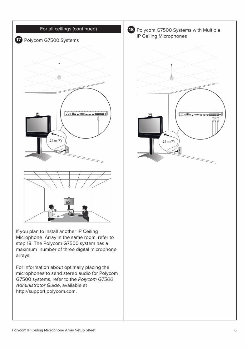
For all ceilings (continued)
17 Polycom G7500 Systems
If you plan to install another IP Ceiling Microphone Array in the same room, refer to step 18. The Polycom G7500 system has a maximum number of three digital microphone arrays.
For information about optimally placing the microphones to send stereo audio for Polycom G7500 systems, refer to the Polycom G7500Administrator Guide, available at http://support.polycom.com.
18 Polycom G7500 Systems with MultipleIP Ceiling Microphones
2.1 m (7’) 2.1 m (7’)

Polycom IP Ceiling Microphone Array Setup Sheet 7
For information about optimally placing the microphones to send stereo audio for Polycom G7500 systems, refer to the Polycom G7500Administrator Guide, available at http://support.polycom.com.
For RealPresence Group SeriesCeiling Microphone Arrays
For information about connecting RealPresenceGroup Series ceiling microphones to the Polycom G7500 system, refer to the Polycom Microphone IP Adapter Setup Sheet, available at http://support.polycom.com.
Product DocumentationDocumentation du produitDocumentación del productoDocumentação do produtoProduktdokumentation www.polycom.com/support