POLICY DOCUMENT · 4.5.1 Compliance Certificate (Category of Accreditation C3) 25 4.5.2 Compliance...
76
Page | 1 POLICY DOCUMENT POLICY NAME POLICY NUMBER Stormwater Drainage Guidelines for Building Developments ES 002 DATE ADOPTED COUNCIL MINUTE NUMBER 28 November 2016 PRC62 ECM NUMBER POLICY TYPE 7604470 Council REVIEW DATE RESPONSIBLE DEPARTMENT June 2020 Engineering Services RELATED DOCUMENTS - Purpose To provide guidance to engineers, designers, architects and developers to ensure that stormwater drainage for building developments is designed to provide a robust, safe and low maintenance system to manage stormwater impacts on the drainage network and surrounding properties in a holistic manner that is incorporated aesthetically with the overall development. Policy Statement Minimise any adverse impacts and prevent damage to the built and natural environment as a result of stormwater runoff from building developments; Manage the quantity of stormwater runoff generated by building developments; Protect the existing public stormwater drainage assets; Minimise the impacts of flooding (mainstream and local) to the built and natural environment; Manage risk to lives and property from the impacts of stormwater and flooding; Ensure the design and construction of the stormwater drainage systems for building developments can be economically maintained; Provide uniform specification and technical requirements in design and construction of stormwater drainage systems for building developments within the Penrith City Council Local Government Area (LGA); and Have uniform approach and ensure consistency in the assessment of stormwater drainage systems for building developments. Scope This policy applies to Building and Development in the Penrith Local Government Area.
Transcript of POLICY DOCUMENT · 4.5.1 Compliance Certificate (Category of Accreditation C3) 25 4.5.2 Compliance...

Page | 1
POLICY DOCUMENT
POLICY NAME POLICY NUMBER Stormwater Drainage Guidelines for Building Developments ES 002
DATE ADOPTED COUNCIL MINUTE NUMBER 28 November 2016 PRC62
ECM NUMBER POLICY TYPE 7604470 Council
REVIEW DATE RESPONSIBLE DEPARTMENT June 2020 Engineering Services
RELATED DOCUMENTS -
Purpose
To provide guidance to engineers, designers, architects and developers to ensure that stormwater drainage for building developments is designed to provide a robust, safe and low maintenance system to manage stormwater impacts on the drainage network and surrounding properties in a holistic manner that is incorporated aesthetically with the overall development.
Policy Statement
Minimise any adverse impacts and prevent damage to the built and natural environment as a result of stormwater runoff from building developments;
Manage the quantity of stormwater runoff generated by building developments;
Protect the existing public stormwater drainage assets;
Minimise the impacts of flooding (mainstream and local) to the built and natural environment;
Manage risk to lives and property from the impacts of stormwater and flooding;
Ensure the design and construction of the stormwater drainage systems for building developments can be economically maintained;
Provide uniform specification and technical requirements in design and construction of stormwater drainage systems for building developments within the Penrith City Council Local Government Area (LGA); and
Have uniform approach and ensure consistency in the assessment of stormwater drainage systems for building developments.
Scope
This policy applies to Building and Development in the Penrith Local Government Area.

STORMWATER DRAINAGE SPECIFICATION FOR BUILDING DEVELOPMENTS
penrithcity.nsw.gov.au

i
STORMWATER DRAINAGE SPECIFICATION
FOR BUILDING DEVELOPMENTS Amendment History
Amendment Date Working Draft Adopted by Council 14 October 2013
Exhibition issue 20 November 2013 Stormwater Drainage Specification for
Building Developments Adopted by PRC – 14 November 2016
Adopted by Council - 28 November 2016 Amended – Section 5.3, 6.4 2 May 2018

ii
TABLE OF CONTENTS
1. INTRODUCTION 1
2. PLANNING CONSIDERATIONS 3
2.1 Submission Requirements 3
2.2 Site Analysis 3
2.3 Impact on Adjoining Properties 4
2.4 Overland Flow Flooding 4
2.5 Earthworks and Retaining Walls 6
2.6 Easements 7
2.6.1 Inter-allotment Drainage Easement 7
2.6.2 Council Drainage Easement 8
2.7 Extension, Relocation or Diversion of Council’s Piped Drainage System 9
2.8 Environmental Issues 9
2.9 Selecting Consultants 10
2.10 Pre-Lodgement Advice 10
3. DESIGN REQUIREMENTS 11
3.1 Council Standards 11
3.1.1 Design Annual Exceedance Probability (AEP) 11
3.1.2 Design Freeboards 11
3.1.3 Tail Water Levels 12
3.1.4 Hazard 12
3.2 Hydrology and Hydraulics 12
3.2.1 Determination of Flow Rates 12
3.2.2 Hydraulic Grade Line Analysis 13
3.3 Internal Drainage Elements 14
3.4 Basement Drainage 14
4. ON-SITE DETENTION (OSD) 15
4.1 Developments Requiring OSD 15
4.2 Reduction of OSD Requirements 16
4.2.1 Overland Flow Paths 16
4.2.2 Large Site (> 5000m2) 16
4.2.3 Rainwater Tanks and WSUD Measures 16
iii
4.3 Design Elements of OSD Systems 16
4.3.1 General 16
4.3.2 Hydraulic Controls 17
4.3.3 Orifice Outlet 17
4.3.4 Discharge Control Pit 18
4.3.5 Sizing of OSD system 18
4.3.6 OSD Above Ground Storage 20
4.3.7 OSD Below Ground Storage 22
4.3.8 Freeboard 22
4.3.9 Emergency Overflow 23
4.3.10 Trash Screen 23
4.3.11 Signage 24
4.4 Construction & Maintenance 24
4.4.1 Construction 24
4.4.2 Maintenance 25
4.5 OSD Certification 25
4.5.1 Compliance Certificate (Category of Accreditation C3) 25
4.5.2 Compliance Certificate (Category of Accreditation C4) 26
5. STORMWATER DISPOSAL 28
5.1 Stormwater Disposal to Council’s System 28
5.1.1 Kerb and Gutter 28
5.1.2 Connection to Council’s Piped Drainage System 28
5.1.3 Piping through Public Owned Land 29
5.1.4 Concrete Lined Channel 30
5.1.5 Natural / Grass Lined Channel 30
5.1.6 Table Drain 31
5.1.7 Inter-allotment Drainage System 31
5.2 For Single Residential Dwellings, Additions and Outbuildings - Alternate Drainage Options 32
5.2.1 Elevated Lines 33
5.2.2 Charged Lines 33
5.3 Rural Dwellings, Additions and Outbuildings 34
5.4 For Minor Areas - Acceptable Drainage Methods 35

iv
5.4.1 Absorption Trenches 35
6. INFORMATION AVAILABLE FROM COUNCIL AND AUTHORITIES 36
6.1 Catchment Information 36
6.1.1 Contour Maps 36
6.1.2 Topographic Maps 36
6.1.3 Piped Stormwater Drainage Network 36
6.2 Flow Rates and Consultant Reports 36
6.3 Flood Information 36
6.3.1 Flood Level Enquiry 37
6.3.2 Flood Report 37
6.4 Section 10.7 Certificate (Previously S149) 37
6.5 Services Location 37
6.6 Council’s Planning Controls and Policies 37
7. APPENDICES 38
Appendix A 38
Checklist for Stormwater Concept Plan (SCP) 38
Appendix B 41
Checklist for Construction Certificate 41
Appendix C 42
Checklist for Occupation Certificate 42
Appendix D 43
On-Site Detention Area - Penrith CBD 43
On-Site Detention Area - Penrith North 44
On-Site Detention Area - Lemongrove 45
On-Site Detention Area - Emu Plains (North) 46
On-Site Detention Area - Emu Plains (west) 47
On-Site Detention Area - Jamisontown 48
On-Site Detention Area - St Marys (East) 49
On-Site Detention Area - St Marys (West) 50
On-Site Detention Area - Colyton 51
On-Site Detention Area - Oxley Park 52
On-Site Detention Area - Dunheved & Werrington 53

v
On-Site Detention Area - Kingswood & Orchard Hills 54
On-Site Detention Area - Cambridge Park 55
On-Site Detention Area - Erskine Park 56
Appendix E 57
Bureau of Meteorology Intensity Coefficients for Penrith 57
Appendix F 59
Standard Terms for Restrictions On the Use of Land and Positive Covenants 59
Overland Flow 59
On-site Detention 60
Basement Pump-out System 61
Water Sensitive Urban Design 62
Appendix G 63
Definitions / Abbreviations 63
Appendix H 65
Standard Drawings 65

vi
TABLE OF FIGURES
Table 1 Theoretical Capacity of Pit 5
Table 2 Width of Drainage Easement 8
Table 3 Design AEP for Stormwater Design Element 11
Table 4 Minimum Freeboard Requirements 11
Table 5 Assumed Tail Water Level at the Point of Discharge 12
Table 6 Coefficient of Roughness 13
Table 7 PSD and SSR 18
Table 8 Permissible OSD discharge and Required OSD storage 19
Table 9 Maximum Depth for Above Ground OSD Basin 20
Table 10 Additional OSD Volume for Above Ground Landscape Storage 21
Table 11 OSD Construction Tolerance 24
Table 12 Minimum Rainwater Tank Size 34

Penrith City Council Page 1 of 68 Stormwater Drainage Specification for Building Developments
1. INTRODUCTION This policy provides guidance to engineers, designers, architects and developers to ensure that stormwater drainage for building developments is designed to provide a robust, safe and low maintenance system to manage stormwater impacts on the drainage network and surrounding properties in a holistic manner that is incorporated aesthetically with the overall development. The objectives of this policy are to:
1. Minimise any adverse impacts and prevent damage to the built and natural environment as a result of stormwater runoff from building developments;
2. Manage the quantity of stormwater runoff generated by building developments; 3. Protect the existing public stormwater drainage assets; 4. Minimise the impacts of flooding (mainstream and local) to the built and natural
environment; 5. Manage risk to lives and property from the impacts of stormwater and flooding; 6. Ensure the design and construction of the stormwater drainage systems for
building developments can be economically maintained; 7. Provide uniform specification and technical requirements in design and
construction of stormwater drainage systems for building developments within the Penrith City Council Local Government Area (LGA); and
8. Have uniform approach and ensure consistency in the assessment of stormwater drainage systems for building developments.
This document sets out Council’s minimum requirements for the provision of stormwater drainage principally to building development sites. Guidance on stormwater drainage design for subdivisions and other trunk drainage works is provided in the relevant Development Control Plan, Council’s “Design Guidelines for Engineering Works for Subdivisions and Developments” and “Engineering Construction Specification for Civil Works”. This document is not intended to be a comprehensive design manual and seeks to use established industry best practise and standards. In this regard, the policy must be read in conjunction with:
State and Regional Environmental Planning Policies; Local Environmental Plans and Development Control Plans; Penrith City Council’s Design Guidelines for Engineering Works for
Subdivisions and Developments; Penrith City Council’s Engineering Construction Specification for Civil Works; Water Sensitive Urban Design Policy; Water Sensitive Urban Design Technical Guidelines NSW Floodplain Development Manual;

Penrith City Council Page 2 of 68 Stormwater Drainage Specification for Building Developments
Australian Rainfall & Runoff; NSW Housing’s Managing Urban Stormwater – Soils and Construction; AS/NZS 3500.3; and Building Code of Australia.
This policy will be revised periodically to embrace new ideas and technologies and to coordinate with updated Council planning and policy.

Penrith City Council Page 3 of 68 Stormwater Drainage Specification for Building Developments
2. PLANNING CONSIDERATIONS 2.1 SUBMISSION REQUIREMENTS
Stormwater design is an important consideration in planning a development and should be considered prior to determination of the final building layout and landscaping treatment. The following documentation is required to be submitted to Council as part of the Development Application:
1. Stormwater Concept Plan (SCP)
Stormwater Concept Plan (SCP), prepared by a suitably qualified person, in which the details in the SCP to be verified against the items in the checklist in Appendix A Note: Failure to provide a satisfactory SCP in accordance with the checklist may result in your application being rejected or refused.
2. Checklist for SCP The completed checklist for SCP in Appendix A
3. Calculations Calculations, based on this policy, Australian Rainfall & Runoff (AR&R) and AS/NZS 3500.3, to support the Stormwater Concept Plan and stormwater drainage design
4. Design Certification Design certification, prepared by a suitably qualified person, to certify the stormwater drainage design is complied with this policy
2.2 SITE ANALYSIS
A preliminary site analysis should be prepared before undertaking the design of the site drainage. This should be undertaken as part of the architectural and landscape preliminary design process. The site analysis should consider all aspects of the development proposal and should integrate the drainage design into the design of any building and landscape works. This is particularly important for identifying overland flow paths and storage areas that may impose level constraints. The drainage site analysis shall include:
Site slope; External overland flow paths entering or adjacent to the site; Existing and proposed ground levels; Existing structures and vegetation on the site as well as adjoining land; Proposed points of discharge; Proposed internal overland flow paths and on-site detention (OSD) storage
areas; Existing and proposed means of access to the site; The hydraulics of the piped network and pipe cover requirements;

Penrith City Council Page 4 of 68 Stormwater Drainage Specification for Building Developments
Location and width of any existing easements (Council/private), Council drainage infrastructure or private inter-allotment drainage system adjacent to or within the site; and
Any other site constraints. 2.3 IMPACT ON ADJOINING PROPERTIES
In assessing a development application, Council needs to be aware of the impact the development will have on adjoining properties. In terms of stormwater, the following issues will be considered:
Changes in site levels shall not cause ponding / backwater effects on upstream properties;
Diversion of flows from one drainage catchment to another will not be permitted; Any development shall not concentrate or increase depth and / or velocity of
overland flows onto an adjoining property; A person has a common law obligation not to carry out any work on their
property that will adversely affect adjoining properties; and The height difference between finished floor levels and natural ground levels
shall be such that, the building complements the adjoining development and meets planning considerations in terms of aesthetics, privacy and building heights.
2.4 OVERLAND FLOW FLOODING
Flooding can occur on a broad scale as riverbank overflows from the greater river and creek catchments (mainstream) or on a local scale due to direct rainfall runoff in a localised catchment (overland flow). As such, in order to determine whether a particular site is affected by mainstream flooding and / or overland flow, the applicant may contact Council’s Engineers for advice or engage a suitably qualified engineer to carry out assessment and site inspection. For site that is affected by mainstream flooding, the applicant shall refer to Penrith City Council’s Development Control Plan Section C3.5 and Council’s Engineers for further requirements and controls. Where a site is impacted by overland flow or substantial stormwater runoff from upstream catchments, the applicant shall demonstrate how the objectives and controls of Penrith City Council’s Development Control Plan Section C3.5 have been complied with and how these flows are to be managed by submission of an overland flow flood report. An overland flow flood report and supporting calculations are required to be submitted by the applicant to Council with the Development Application documentation on properties that are affected by the overland flow flooding, particularly when the following apply:
Council’s drainage easement / drainage reserve and / or stormwater drainage system (including open / covered channel, watercourse and underground drainage pipes / culverts) is located within / adjacent to the site; or

Penrith City Council Page 5 of 68 Stormwater Drainage Specification for Building Developments
The site is within or directly adjoining a major overland flow path or flood area identified by Council; or
The site is located at or adjacent to a sag point in the catchment. The overland flow flood study shall be prepared by a suitably qualified hydraulic engineer experienced in the preparation of the flood study and shall include but not limited to the following information:
a) Catchment plan highlighting the full upstream catchment area that generates the overland flow;
b) A pre-development (existing conditions) and post-development detailed hydrological and hydraulic analysis based on the 1% AEP storm for the upstream catchment area; Note: DRAINS and HEC-RAS are the preferred computer programmes to be used. The following theoretical capacity of pit shall be applied in order to consider pit blockage
(adopted by Council on 7 August 2006). Table 1 Theoretical Capacity of Pit
Pit Condition Pit Inlet type Percentage of Theoretical Capacity Allowed
Sag Side entry 80% Sag Grated 50%
Sag Combination Side inlet capacity only. Assume grate is completely blocked.
Sag Letterbox 50% Continuous Grade Side entry 80% Continuous Grade Grated 50% Continuous Grade Combination 90%
c) A scaled plan view showing the existing and proposed 1% AEP overland flow
path extent and levels on the subject property; d) A longitudinal section (at the vertical scale 1:50, horizontal scale to that of plan
view) of the drainage system showing existing and proposed surface levels, 1% AEP floodwater levels, hydraulic data and all changes in grade;
e) Scale 1:50 cross-section details of the overland flow path with a maximum spacing of 5m between cross-sections, at least including the following locations:
i. Immediately at the upstream property boundary; ii. Where the existing and proposed development / structure is closest to
the flow path; iii. Immediately at the downstream property boundary; and iv. Other cross-sections as required where the flow path and / or drainage
system is being affected. Note: Cross-sections must show the existing and proposed ground levels, pre- and post-
development top water levels, flood extents and hydraulic data.
f) Consideration of cumulative impacts of the post-development overland flows to upstream and downstream properties;
g) A copy of landscape plan to demonstrate consistency with the overland flow report; and

Penrith City Council Page 6 of 68 Stormwater Drainage Specification for Building Developments
h) Statement signed by a suitably qualified engineer declaring that the assessment has been undertaken in accordance with Australian Rainfall and Runoff and the NSW Floodplain Development Manual.
The following key principles shall also be considered in the overland flow flood study:
All levels shown shall be to the Australian Height Datum (AHD) The development shall not adversely impact on surrounding properties through
the diversion, concentration or ponding of overland flows (i.e. the extent, velocity and the depth of overland flow shall remain unchanged);
The development shall not impede the passage of overland flow to cause a rise (afflux) in the water levels and / or increase velocities of flow on adjoining lands;
The development shall accommodate the passage of overland flow over the site and, where applicable, shall be designed to withstand damage due to scour, debris and buoyancy forces;
The development must not be sited where overland flows may result in a hazardous situation for future occupants in terms of depth and velocity of overland flows through the property (i.e. velocity-depth product greater than 0.4 is not acceptable);
Overland flows shall be directed through common areas and not through private courtyards or on-site detention systems;
The overland flow path must not be obstructed by landscaping, kerbing, retaining walls, fencing or the like;
No structures and / or filling are permitted within the overland flow path unless suitable flood mitigation measures approved by Council are to be implemented;
Any fencing (including boundary fencing) over the extent of the overland flow path must be replaced with open style fencing or similar to allow the free passage of overland flows;
Design elements such as concrete or paving shall be used to fix critical levels in overland flow paths to minimise interference by future occupiers; and
Provision of adequate freeboard to finished floor levels in accordance with Section 3.1.2 of this policy.
Where considered necessary, Council may impose conditions of consent on a proposed development to protect overland flow paths. A Restriction on the Use of Land and Positive Covenant may also be required to protect overland flow paths. The standard terms of Restriction on the Use of Land and Positive Covenant are available in Appendix F. 2.5 EARTHWORKS AND RETAINING WALLS
Developments involving earthworks and retaining walls need to have regard for the amenity of any adjoining / surrounding properties and the natural flow of water across the land. Any development proposal for earthworks shall have due regard to the following issues:
Cut and fill must comply with Council’s Local Environmental Plan and Development Control Plan;
The level of cut and fill shall be minimised and in balance where practical;

Penrith City Council Page 7 of 68 Stormwater Drainage Specification for Building Developments
Significant filling works must comply with the requirements in Council’s “Design Guidelines for Engineering Works for Subdivisions and Developments” and “Engineering Construction Specification for Civil Work”;
Consideration shall be given to adjoining properties in terms of privacy and overshadowing;
Excessive filling (> 1000mm) for drainage will not be supported for land that falls away from the street;
Proposed filling and retaining walls shall not adversely impact adjoining properties with regard to overland flows;
Any landfill shall be designed such that levels blend into the natural land form, complementing the existing landscape;
Any proposed earthworks (cutting / filling) and retaining walls to redirect stormwater runoff from one sub-catchment to another, if supported by Council’s Engineers, shall submit hydraulic analysis to address its impacts to the capacity of receiving street gutter, stormwater drainage system and adjoining and downstream properties, as well as the amenity of adjoining properties;
Retaining walls along or near common property boundaries shall be designed with due consideration to common fence lines and adjoining property levels; and
Structural Engineering certificates shall be provided for retaining walls exceeding 600mm in height.
2.6 EASEMENTS
2.6.1 INTER-ALLOTMENT DRAINAGE EASEMENT
All developments must have a legal drainage connection to the street / public drainage system. For sites where the provision of a private stormwater system / drainage connection will be across property boundaries (except road reserve), easements for drainage purposes shall be created over the affected properties, in favour of the site being developed. In most cases, this will be applied to where the proposed development site slopes away from the street. Where drainage easements are required over downstream and / or adjacent properties, the following will be applied:
1. A written agreement from the registered proprietor(s) granting an easement to drain water shall be submitted with the Development Application. Such an agreement must acknowledge the location and width of the required easement consistent with this policy.
2. All easements to drain water over downstream and / or adjacent properties are required to be registered with NSW Land and Property Information and a copy of the registration shall be submitted to Council prior to the consent becoming operational.
3. In most circumstances, structures will not be permitted to encroach upon an easement to drain water. The foundations of adjoining structures shall not be within the zone of influence of the drainage trench. Similarly the location of proposed easements and associated drainage infrastructure shall be located

Penrith City Council Page 8 of 68 Stormwater Drainage Specification for Building Developments
so that the zone of influence of existing buildings and structures are not compromised.
4. No filling or other works will be permitted in the drainage easement which will adversely impact on:
The conveyance of surface flows; The condition and loading on the drainage infrastructure; and The rights and costs of the beneficiaries to access, maintain and
replace the drainage infrastructure as required. 5. The width of drainage easement created shall fully accommodate overland
flows from the upstream catchment up to the 1% AEP design storm event. The minimum width of the required stormwater drainage easement shall be as follows:
Table 2 Width of Drainage Easement Drainage easement
Pipe Diameter (D) (mm) Easement Width(1) (m)
150(2) 1.5(3) 225-300(2) 2.0
375-600 2.5 675-1050 3.0
1200-1500 3.5 1650-1800 4.0
> 1800 D + 1m on each side of the pipe(4) Twin Pipes 2D + 2.5m + distance between pipes
Culvert D + 1m on each side of the culvert(4) Open Channels 1m + top width of 1% AEP design flow
with 500mm freeboard Notes: (1) Subject to the depth of proposed pipes, the easement width may need to increase (2) Not applicable to Council piped drainage system. (3) Under exceptional circumstance, such as constraints of the site, lesser width down to absolute minimum of 1.0m may be considered by Council subject to the assessment and approval from Council’s Engineers. (4) Measured from the outer edge of the pipe / culvert / culvert slab. 2.6.2 COUNCIL DRAINAGE EASEMENT
In cases where existing Council drainage infrastructure is located within the development site and at the time such infrastructure is not protected by a drainage easement, or not within its easement, the applicant shall:
1. Provide details of the existing Council drainage infrastructure (including depth, location and size) as determined by a registered surveyor; and
2. Create a drainage easement, with minimum width in accordance with this
specification and Penrith City Council’s “Design Guidelines for Engineering Works for Subdivisions and Developments”, over the existing Council drainage infrastructure in favour of Council.

Penrith City Council Page 9 of 68 Stormwater Drainage Specification for Building Developments
2.7 EXTENSION, RELOCATION OR DIVERSION OF COUNCIL’S PIPED DRAINAGE SYSTEM
If a development proposal requires the extension, relocation or diversion of Council’s piped drainage system, then this will need to be discussed with Council’s Engineers prior to the preparation of concept plans for the site. Council’s Engineers will consider the suitability of a proposal where it can be demonstrated that:
The capacity of Council’s drainage system is not decreased which may require upsizing of the pipe network;
Adequate provision is made for overland flow paths; There is no adverse impact on adjoining properties; and Council has adequate construction and maintenance access.
Any proposal to extend, relocate or divert Council’s piped drainage system will need to be supported by a detailed hydrological and hydraulic analysis. 2.8 ENVIRONMENTAL ISSUES
In assessing the suitability of a Development Application and associated stormwater concept plan there are various environmental issues to consider. These issues include salinity, acid sulphate soils, groundwater, contamination, water quality, water conservation, water cycle management, water sensitive urban design, catchment management and impact on natural systems. These environmental considerations are addressed by various legislation and may require consultation with State and Local authorities. Any development proposal must address the following key principles:
The development must not adversely impact upon natural characteristics such as trees to be retained and natural drainage systems;
The development must comply with BASIX requirements where applicable; Incorporate Water Sensitive Urban Design (WSUD) principles in accordance
with Council’s Development Control Plan and Water Sensitive Urban Design Policy;
Any proposed infiltration systems as part of WSUD must be lined as direct stormwater infiltration to ground is not permitted due to the soils in the Penrith LGA being predominantly impermeable, saline and / or sodic clays;
Water Sensitive Urban Design measures shall be provided as required by Council’s Development Control Plan and Water Sensitive Urban Design Policy; and
Where cut in excess of 1m is provided Council may require an assessment of impact on salinity, acid sulphate soils and groundwater.
A Restriction on the Use of Land and Positive Covenant will be required to protect Water Sensitive Urban Design measures. The standard terms of Restriction on the Use of Land and Positive Covenant are available in Appendix F.

Penrith City Council Page 10 of 68 Stormwater Drainage Specification for Building Developments
2.9 SELECTING CONSULTANTS
The choice of qualified and experienced consultants with an understanding of Council’s requirements and relevant specifications and standards can expedite the approval of developments submitted to Council. Experienced consultants are also more likely to provide a more amenable and cost effective design. The design and certification of on-site detention (OSD) systems and site drainage set out in this document will only be accepted from persons having suitable professional accreditation. The following are considered to be acceptable accreditation for the purpose of OSD and site drainage design and certification:
NPER in Civil Engineering (Engineers Australia); Surveyors Certificate of Accreditation in On-Site Detention and Drainage
Design (Institution of Surveyors, NSW and the Association of Consulting Surveyors, NSW);
Stormwater Register (Association of Hydraulic Services Consultants, Australia); and
An Accredited Certifier under the Environmental Planning and Assessment Act 1979 accredited in the relevant discipline.
The designers shall identify their professional accreditation in the design submission with the Development Application, Construction Certificate and Works-As-Executed submission. 2.10 PRE-LODGEMENT ADVICE
Council facilitates regular pre-lodgement meetings and encourages developers to attend such meetings prior to submitting a Development Application. Council’s pre-lodgement team will include an environmental planner, development engineer, building surveyor and other professionals as required. Pre-lodgement meetings can be booked through Council’s Development Services Department on 4732 7777. The pre-lodgement advice service allows the developer to discuss their proposal with Council and receive holistic and coordinated advice to identify issues regarding any constraints or non-compliances with Council’s planning controls and policies. However, the onus remains on the developer to ensure that all relevant controls and issues are considered prior to the submission of a Development Application. Information given by the pre-lodgement panel does not constitute a formal assessment of the proposal and at no time should comments be taken as a guarantee of approval of the proposal.

Penrith City Council Page 11 of 68 Stormwater Drainage Specification for Building Developments
3. DESIGN REQUIREMENTS 3.1 COUNCIL STANDARDS
3.1.1 DESIGN ANNUAL EXCEEDANCE PROBABILITY (AEP)
The following design AEPs shall be applied to the following components of the stormwater system: Table 3 Design AEP for Stormwater Design Element
Stormwater Design Element Design Annual Exceedance
Probability (AEP) Residential Others
Internal Roof and Surface Drainage Systems 5%(1) 5%(1) Inter-allotment Piped Drainage Systems 20%(2) 5%(2)
Overland Flow Paths 1% OSD systems 1%
Notes: (1) Must be increased to 1% AEP for OSD systems where surface drainage is not directed to the system. (2) Must be increased to 1% AEP where no overland flow path is provided. Council may require the adoption of a higher design AEP in circumstances where danger to persons or risk of significant property damage warrants such an approach. 3.1.2 DESIGN FREEBOARDS
In order to provide reasonable certainty avoiding the risk exposure of flooding and stormwater to the building, freeboard - a factor of safety - is required to set the floor levels, levee crest levels etc. In general, the following minimum freeboard requirements measured from the 1% AEP flood / top surface level shall be complied with: Table 4 Minimum Freeboard Requirements
Description Minimum Freeboard (mm)
Overland Flow Flooding:(1)
OSD Systems:
Residential, Industrial or Commercial floor levels 500 300 Garages and non-habitable floor levels 100 100(2)
Crest of driveway ramps, pedestrian entry points and any openings to the basement (e.g. vents) 300 300
Notes: (1) Properties affected by mainstream flooding must meet the requirements of Penrith City Council’s Development Control Plan Section C3.5. (2) This minimum freeboard requirement also applies to the enclosed basement garages adjacent to the pump-out system. For emergency response facilities (e.g. police stations, hospitals), critical infrastructures and other types of developments that required special evacuation needs (e.g. schools, aged care facilities, disabled and child care facilities), adoption of design storm events larger than 1% AEP design storm events and higher freeboard requirements and may be necessary.

Penrith City Council Page 12 of 68 Stormwater Drainage Specification for Building Developments
3.1.3 TAIL WATER LEVELS
The adopted tail water for the drainage system shall be designed to be 1% AEP downstream level at the point of discharge or in accordance with the following criteria, whichever is higher. Table 5 Assumed Tail Water Level at the Point of Discharge
Point of Discharge Tail water Level Kerb discharge Top of kerb
Kerb inlet pit Top of kerb (1% AEP) Grate level of pit (20% AEP)
Junction pit Surface level at pit Free outlet Obvert of discharge pipe
Stormwater channel Top of channel Natural watercourse Top of bank
Dam Top of spillway Water body Top water level (1% AEP)
The tail water levels may be varied where supported by a full hydrological and hydraulic analysis of the receiving drainage network. 3.1.4 HAZARD
In order to minimise hazard, any developments affected by 1% AEP overland flow flooding shall be designed to comply with the following:
The velocity and depth product of overland flow path shall be less than 0.4; The depth of flood water shall be less than 0.8m; and The velocity of flood water shall be less than 2m/s.
Council may require a lower ratio where the proposed use of the development (e.g. emergency response facilities and critical infrastructure and other types of developments that required special evacuation needs) may warrant higher safety standards. 3.2 HYDROLOGY AND HYDRAULICS
The following standards shall be taken into account when preparing hydrological and hydraulic information to support an application: 3.2.1 DETERMINATION OF FLOW RATES
Flow rates shall be determined in accordance with the procedures outlined in Australian Rainfall and Runoff (AR&R) and Council’s “Design Guidelines for Engineering Works for Subdivisions and Developments” and “Engineering Construction Specification for Civil Work”. The Rational Method in association with the kinematic wave equation is an acceptable method for determining flow rates where the catchment is relatively small (< 1Ha), has fairly uniform characteristics and the level of accuracy is not critical. A maximum time of concentration (tc) of 20 minutes and a minimum coefficient C100 = 0.84 for urban catchments shall be used when determining flow rates.

Penrith City Council Page 13 of 68 Stormwater Drainage Specification for Building Developments
Where catchments are large and an accurate level of flow rate prediction is necessary, peak flow rates shall be determined using a recognised runoff routing computer model. Council’s preferred model is DRAINS. Council has some information in terms of flow rates for larger catchments and these will be made available for use by the hydraulic consultant where appropriate. Where these flow rates have been provided, Council will not accept alternative flow rates unless it can be demonstrated that the modelling procedure used to determine the flow rate is more accurate than Council’s model. Rainfall Intensity- Frequency Duration charts are provided in Appendix E for assistance in preparing a submission to Council. Determination of overland flow rates should also account for blockage factor (refer to Section 2.4) to all inlet pits. Pit inlet capacities and roughness coefficients must be determined in accordance with AR&R. 3.2.2 HYDRAULIC GRADE LINE ANALYSIS
A hydraulic grade line (HGL) analysis is required for the piped stormwater drainage in either one of the following instances: All inter-allotment drainage lines; Extension / Relocation / Diversion of Council’s Piped Drainage System; Property drainage connecting into a Council piped drainage system; In situations where determination of hydraulic control is critical as determined by
Council’s Engineers; or Where pipe discharge exceeds 100L/s or as directed by Council’s Engineers. In cases where determination of the HGL is critical to the successful implementation of a design, such an analysis will be required to be submitted with the development application. In general, friction losses in pipes shall be determined using the Darcy Weisbach equation. In most cases the design coefficients of roughness shall be in accordance with the following values: Table 6 Coefficient of Roughness
PIPE MATERIAL COLEBROOK WHITE “k” (mm) uPVC 0.03
Reinforced Concrete 0.60 FRC 0.15
Shock losses at pits, slope junctions, bends, transition structures, inlets and outlets shall also be considered. Reasonable kU values shall be selected using “Missouri charts”, Hare equations, US Corp of Engineers mitre bend charts or other recognised procedures. Any kU values selected shall be appropriately identified in the submitted documentation.

Penrith City Council Page 14 of 68 Stormwater Drainage Specification for Building Developments
3.3 INTERNAL DRAINAGE ELEMENTS
Roof drainage and internal surface and subsoil drainage system shall be designed and constructed in accordance with AS/NZS 3500.3. The following additional criteria must be met for development in the Penrith Local Government Area:
Grated pit (min 450mm x 450mm) shall be provided adjacent to property boundaries for any stormwater outlet pipe connections to kerb and gutter / Council piped drainage system / inter-allotment drainage system; and
The placement of stormwater pipes beneath buildings is not permitted except where there is no alternative option for pipes to lay around the buildings.
Provision of pump-out system, charged lines system, elevated lines system and absorption system will not be permitted for any developments excepted as stated in Section 3.4, Section 5.2, Section 5.3 and Section 5.4.
3.4 BASEMENT DRAINAGE
A basement pump-out system will only be permitted for subsoil drainage and minor undrained areas, such as driveways and stairs leading to basement car parking areas, where the total area draining to the basement is less than 100m2 and the following criteria shall be complied with:
a) The pump-out system shall be designed in accordance with AS/NZS 3500.3; b) The pump-out system shall comprise of minimum two (2) submersible type
pumps. The two pumps shall be designed to work on an alternative basis to ensure both pumps receive equal use and neither remains continuously idle;
c) Each pump shall have a minimum capacity of 5 L/s or shall be based on the flow rate generated from a 1% AEP 5-minutes duration storm event of the area of the ramp that draining into the system, whichever is greater;
d) An alarm warning device (including signage and flashing strobe light) shall be provided for the pump-out system to advise the occupant of pump failure. The location of the signage and flashing strobe light shall be shown on the stormwater management plans;
e) The volume of the pump-out tank shall be designed with a minimum storage capacity equivalent to the runoff volume generated from of the area of the ramp that draining into the tank for a 1% AEP 2-hours duration storm event;
f) Backflow prevention devices / measures shall be provided to the outlet of the pump-out system to minimise or eliminate the risk of backflows into the basement;
g) For the basement area below the groundwater table, no subsoil drainage system shall be provided and the underground structure shall be protected by waterproofing; and
h) A Restriction on the Use of Land and Positive Covenant will be required to protect the basement pump-out system. The standard terms of Restriction on the Use of Land and Positive Covenant are available in Appendix F.

Penrith City Council Page 15 of 68 Stormwater Drainage Specification for Building Developments
4. ON-SITE DETENTION (OSD) 4.1 DEVELOPMENTS REQUIRING OSD
Council has identified the following specific local catchments in Penrith Local Government Area where on-site stormwater detention (OSD) is mandatory (Appendix D):
Penrith CBD Penrith North Lemongrove Emu Plains Jamisontown St Marys Colyton Oxley Park Dunheved & Werrington Kingswood & Orchard Hills Cambridge Park Erskine Park
OSD is generally required for all types of developments in these areas except the following:
Single dwelling development, including outbuildings, alterations and additions; Dual occupancy, secondary dwelling and granny flat development; Development in rural area where the size of impervious areas is less than
1000m2; Subdivision of any existing development in which OSD has already been
provided; Boundary adjustment and consolidation of allotments where no additional lots
are created; Change of use where there is no increase of impervious area. New development in subdivisions where OSD / detention basin / retarding
basin has already been provided for the entire subdivision Grassed playing field and vegetated area of public sports and recreational
facilities One-off minor development, including alterations and additions, where the
proposed area of development is less than 100 m2 (subsequent minor developments or additions shall require OSD).
Where a designer chooses to provide OSD to reduce flows to utilise an existing under capacity drainage system, then all of the provisions of this section of policy shall apply.

Penrith City Council Page 16 of 68 Stormwater Drainage Specification for Building Developments
4.2 REDUCTION OF OSD REQUIREMENTS
Generally for any development or redevelopment of a site, OSD requirements apply to the entire site, but Council may consider to reduce the requirements in the following circumstances subject to a detailed assessment: 4.2.1 OVERLAND FLOW PATHS
For sites that are impacted by 1% AEP major overland flow paths identified in Council’s adopted flood studies, Council may delete or reduce OSD requirements for developments. The area covered by the major overland flow may be excluded from the site area in determining the Permissible Site Discharge (PSD) and Site Storage Requirement (SSR) of OSD system. 4.2.2 LARGE SITE (> 5000M2)
Where a large site is to be partly redeveloped, the area of existing building and paved surfaces may be excluded from the OSD requirements subject to no physical works to be carried out in these areas and the following factors:
Total area of the site; Percentage of the site area to be redeveloped; The impervious proportion of the site; The impacts on surrounding land uses; Extent of drainage / flooding issues in surrounding area; Capacity of the existing drainage network; Cumulative impact of increased impervious area; and Impact on downstream properties.
4.2.3 RAINWATER TANKS AND WSUD MEASURES
Council does not allow a reduction in OSD storage volumes for rainwater tanks or any WSUD measures (e.g. rain gardens, bio-retention system, swale etc.). 4.3 DESIGN ELEMENTS OF OSD SYSTEMS
4.3.1 GENERAL
The following general principles must be applied when designing the OSD system:
a) Wherever possible, OSD storage shall be generally located near the lowest point of the development site;
b) OSD storage is not permitted in private courtyards, overland flow paths / floodways, natural watercourses or effluent disposal areas;
c) Above ground OSD storage should be provided in common landscaped area, driveways, turning bays or other hardstand areas;
d) Any runoff from the external catchments of the OSD system shall be diverted around the OSD storage unless the storage has been designed to accommodate the external flows;

Penrith City Council Page 17 of 68 Stormwater Drainage Specification for Building Developments
e) The design must consider the practical operation of the system as well as maintenance considerations such as location and size of access pits;
f) Internal flow paths through private courtyards should be minimised; g) Site levels shall be designed to direct all surface flows into the OSD system.
This will ensure that in the storm events larger than 1% AEP or the event of a failure of the roof and piped system that flows are still directed to the storage area so as not to adversely affect adjoining properties and to maintain the integrity of the OSD system;
h) Driveway and parking areas shall be shaped to direct flows into the OSD system. The use of grated drains for this purpose should be avoided wherever possible;
i) The OSD system, including storage, shall be wholly located within the property boundary; and
j) Site stormwater runoff shall be collected and conveyed to the OSD system and WSUD measures.
4.3.2 HYDRAULIC CONTROLS
The following hydraulic controls shall be applied to the design of OSD systems:
All pits connected to an OSD system shall be minimum 100mm above the top water level to ensure there is not surcharge due to tail water levels in the storage area;
The outlet pipe diameter from the OSD system shall be a minimum of 1.5 x the orifice pipe; and
The outlet control for the OSD system shall be above the following levels, whichever is the greatest:
o Council’s adopted tail water level (Section 3.1.3); or o 1% AEP flood level at the discharge point; or o Hydraulic grade line level of the connection to street or piped drainage
system. Note: Submerged OSD outlet is not acceptable
4.3.3 ORIFICE OUTLET
The OSD system outlet shall generally be controlled by an orifice. However, Council may consider staged-outlet orifice design to control site runoff from a range of storm events, subject to assessment and approval from Council’s Engineers. The following requirements apply to the design of orifice outlet:
The orifice shall have an absolute minimum diameter of 25mm; Orifice plate shall be manufactured from minimum 3mm thick stainless steel
plate (6mm where orifice diameter exceeds 150mm), with circular hole machines to 0.5mm accuracy and sharp-edged;
The centreline of the orifice shall be installed to align with the centre line of the outlet;

Penrith City Council Page 18 of 68 Stormwater Drainage Specification for Building Developments
Orifice plate shall be fixed to the wall of the control pit by four (4) stainless steel ‘dyna bolts’ or equivalent, at each corner, with epoxy seal around the edges of plate to prevent entrance of water; and
The orifice discharge equation is:
Q = C A (2gh) 1/2
where Q is the discharge in m3/s
C is the coefficient of discharge
A is the orifice area in m2
g is the acceleration due to gravity (m/s2)
h is the depth of water above the centre of the orifice (m).
This equation relies on a circular sharp-edged orifice and free discharge from the orifice.
4.3.4 DISCHARGE CONTROL PIT
The minimum size of the discharge control pit shall be:
600mm x 600mm for pits up to 900mm depth. 900mm x 900mm for pits greater than 900mm depth.
The discharge control pit shall:
Minimise the risk of becoming blocked by debris; Be located in a suitable position; Be readily inspected; Be fitted with hinged galvanised mild steel grate and trash screen (Lysaght
Maximesh RH3030 or equivalent) with a minimum area of 50 times the orifice area;
Be provided with galvanised step irons if the internal depth of the pit is greater than 1.0m;
Be accessed readily for cleaning; and Have a minimal risk of being tampered with.
Refer to Appendix H for the standard drawings of the typical OSD Discharge Control Pit and typical OSD designs in developments. 4.3.5 SIZING OF OSD SYSTEM
For site areas up to 5000m2 (0.5 hectares), Council has adopted a simplified method in determining Site Storage Requirement (SSR) and Permissible Site Discharge (PSD) of the OSD system as set out below. Table 7 PSD and SSR
Land Use PSD (L/s/ha) SSR (m3/ha) Multi-Unit Housing 120 240 Residential Flat Building / Apartment / Industrial / Commercial and Others
120 280

Penrith City Council Page 19 of 68 Stormwater Drainage Specification for Building Developments
Where possible, the stormwater drainage system should be designed to direct runoff from the entire site to the OSD system. Should this not feasible due to ground levels, the receiving drainage system or other special circumstances, not more than 15% of the total site area will be permitted to bypass the OSD system. If more than 15% of the site cannot be drained to the main OSD system, an additional system shall be provided. For each square metre of area bypassing the OSD systems, the permissible discharge and the required storage volume of the OSD system shall be adjusted accordingly. The following table provides the relationship between area bypassing and the permissible OSD discharge and required OSD storage. Table 8 Permissible OSD discharge and Required OSD storage
Area bypassing (% of the total site)
Permissible OSD Discharge (L/s/ha)
Required OSD Storage (m3/ha)
Multi-Unit Housing (1)
RFB Apartment / Industrial / Commercial and Others (2)
0% 120 240 280 1% 113.9 249 289 2% 107.8 258 299 3% 101.7 268 310 4% 95.6 279 320 5% 89.5 290 331 6% 83.4 301 343 7% 77.3 313 358 8% 71.2 329 373 9% 65.1 344 389
10% 59.0 360 406 11% 52.9 379 429 12% 46.8 403 452 13% 40.7 427 484 14% 34.6 466 526 15% 28.6 512 572
Notes: (1) Required OSD Storage = 81.877 x (Permissible OSD Discharge)-0.52. (2) Required OSD Storage = 100.16 x (Permissible OSD Discharge)-0.493. Where the development site area is greater than 5000m2, specific site analysis shall be undertaken using an appropriate computer model, Council’s preferred model is DRAINS. As a minimum it will be necessary to demonstrate that there will be no increase in runoff from the site as a result of the development under all durations for all the storms up to and including the 1% AEP event. Where the downstream drainage system has limited capacity or may result in increased flooding, the OSD system shall be designed to match the capacity of the downstream system or ensure no increase in flood levels. A design report including a stormwater drainage plan consistent with the computer modelling layout, a summary of any modelling results, catchment plans, all assumptions and model parameters used shall be submitted with the Development Application. Computer output shall be attached as an appendix to the design report.

Penrith City Council Page 20 of 68 Stormwater Drainage Specification for Building Developments
All input and output files for computer programs utilised are to be provided on a CD, DVD etc., together with a list of files and a brief explanation relating to each file. Where manual calculations or spreadsheets for the hydrological or hydraulic design are used, they shall be clearly written and set out the process followed, assumptions made and parameters adopted. For large developments or subdivision release areas the general principles set out in Australian Rainfall and Runoff (AR&R) shall be utilised in the analysis and design of such basins. These developments should be discussed with Council’s Engineers prior to finalising the concept design. 4.3.6 OSD ABOVE GROUND STORAGE
The maximum depth of OSD above ground storage shall be in accordance with the values set out below. Table 9 Maximum Depth for Above Ground OSD Storage
Storage Location Maximum Depth(1) (mm) Hardstand areas used for car parking and
pedestrian access 200
Landscaped areas 600 Large commercial / industrial open basins
(greater than 50m3) 1200
Notes: (1) Wherever the maximum depth requirements cannot be achieved, the designer shall consider to provide OSD storage below ground. The following criteria shall be addressed in the OSD above ground storage design: Above ground storage in hardstand areas for car parking and pedestrian access:
a) The first 10% or 2m3 of the storage volume, whichever is the greater, shall be provided underground or in an area where access is not required or the frequent ponding in minor storms will not create a nuisance;
b) Any shaping of car parking area or driveways shall ensure the gradients of vehicle access complying with the criteria set out in AS/NZS 2890.1, AS/NZS 2890.2 and / or AS/NZS 2890.6;
c) Any shaping of pedestrian accessible area shall comply with the gradients as stated in AS1428 and Building Code of Australia;
d) Stored water shall not inundate gardens or areas with bare soil, mulch or the like around parking or other hardstand areas. These areas should be above the storage top water level or protected by concrete kerbing or other robust treatment capable of withstanding vehicle impact. Timber kerbing is not permitted;
e) For development under State Environmental Planning Policy (Housing for Seniors or People with a Disability) 2004, the gradients of vehicles access and hardstand area shall comply with the criteria set by the SEPP; and
f) Paved areas shall have a minimum grade of 1% for concrete, 2% for pavers / asphaltic concrete (AC) and 3% for bitumen seal.
Above ground storage in landscaped areas:

Penrith City Council Page 21 of 68 Stormwater Drainage Specification for Building Developments
a) Landscaped storage areas must be within common property; b) The design should be undertaken in consultation with the landscape designer
to ensure that the plans are not in conflict; c) The first 10% or 2m3 of the storage volume, whichever is the greater, shall be
provided underground or in an area where not required for access and frequent ponding in minor storms will not create a nuisance;
d) Where landscaped areas are to be used, the required volume shall be increased to accommodate any potential mature planting within the basin. The additional volume shall be provided as outlined below;
Table 10 Additional OSD Volume for Above Ground Landscape Storage Design Storage Volume Additional Volume Required
5m3 or less 50% between 5m3 and 25m3 25%
greater than 25m3 15%
e) Careful consideration shall be given to types of planting and landscaping treatment within the basin, to ensure the area can be readily maintained and the storage volume is not reduced over time;
f) Landscaping shall be designed so as not to generate large amounts of debris or other material likely to cause stormwater pollution. Treatments such as wood chips / mulch or bare soil and the like shall not be permitted within the area of inundation;
g) Vertical sides near driveways or pedestrian areas should be protected with an appropriate treatment such as fencing, kerb, edging or landscaping to minimise hazard to pedestrians and vehicles;
h) Suitable access shall be provided for maintenance purposes which may include ramps or accessible gradients;
i) Consideration must be given to the likelihood of access by children in rainfall events and the subsequent need for fencing or other controls;
j) Where fencing is required it shall be childproof pool type fencing including a self-closing gate;
k) Subsoil drainage shall be installed in landscaped storage areas to prevent the area remaining saturated during wet weather;
l) The base of landscaped storage is to have a minimum 1% fall to the outlet pit; m) Any buildings forming the walls of the above ground storage shall be
adequately waterproofed to prevent water entering the sub-floor area; n) Any retaining walls surrounding the above ground storage, including spillway,
shall be in watertight concrete or masonry construction (timber construction is not permitted) and structurally adequate to accommodate the hydrostatic loading from full storage; and
o) Batter slopes in landscaped areas shall be generally 1:6 (v:h). Steeper slopes may be permitted subject to the approval of Council’s Engineers. Any request for steeper slopes must indicate the benefit and adequately address safety and maintenance issues. Large open grassed basins may be permitted in commercial or industrial development. These open basins shall have minimum base dimensions of 5m and shall have 1:6 (v:h) internal batters, with walls to be designed by a suitably qualified and experienced geotechnical engineer. Childproof fencing and lockable gate may be required.

Penrith City Council Page 22 of 68 Stormwater Drainage Specification for Building Developments
The design of aboveground tanks must consider appearance and urban design issues. Aboveground tanks shall comply with the same engineering criteria as belowground tanks. Particular attention should be given to access for inspection and maintenance. 4.3.7 OSD BELOW GROUND STORAGE
The following design criteria must be met for below ground storage tanks:
a) Storage tanks are not permitted under habitable floors or any building slabs; b) For dual use tanks any permanent water storage volumes will not count as part
of the OSD required storage; c) Storage tanks shall not be penetrated by any site services such as water, sewer,
electricity and gas etc.; d) The tank shall have a minimum depth of 900mm to facilitate access for
maintenance and cleaning. Consideration may be given to reduce the depth of the tank up to 750mm subject to the assessment and approval from Council’s Engineer;
e) A minimum of two grated access points (900mm x 900mm) shall be provided on opposite sides of the tank to facilitate ventilation, one shall be located over the discharge control pit / screen for maintenance and cleaning;
f) Larger tanks may require additional grates to provide adequate ventilation; g) The spacing between each access grates shall comply with AS2865; h) All access points shall be fitted with a minimum of 900mm x 900mm removable
or hinged heavy duty grate; i) Step irons shall be provided to all access points at 300mm centres to allow for
comfortable access; j) Grates should be fitted with appropriate locking mechanisms to prevent ingress
by children or non-authorised persons; k) For safety, all maintenance access to pits must conform to current Australian
Standards and regulations for confined spaces. It is the responsibility of the designer to ensure compliance with these requirements and other requirements associated with Occupational Health and Safety;
l) The location of the tank and inspection access should also consider safety of persons undertaking maintenance and inspections. Access points should be located away from driveways or heavily trafficked areas wherever possible;
m) The floor of the storage tank shall be graded at a minimum of 1% longitudinally and laterally to the outlet to ensure free and complete dewatering of the system;
n) The tank shall be reinforced concrete or masonry; and o) The tank shall be certified by an appropriately qualified and experienced
engineer for structural adequacy against appropriate live and dead loads, earth loads, traffic, internal hydrostatic loads as well as external hydrostatic loads (buoyancy).
4.3.8 FREEBOARD
Refer to Section 3.1.2 for the freeboard requirements of the OSD system.

Penrith City Council Page 23 of 68 Stormwater Drainage Specification for Building Developments
4.3.9 EMERGENCY OVERFLOW
Consideration must be given to emergency overflow from the OSD storage structure in the case of the drainage system failing because of blockage or during storm events exceeding the 1% AEP. The following shall be complied with:
a) A minimum 900mm x 900mm overflow pit and an emergency overflow weir shall be incorporated into the OSD design to collect emergency overflow. The overflow pit shall be directly connected to the outlet pipe connections in kerb and gutter / Council piped drainage system / inter-allotment drainage system;
b) Emergency overflow from the weir shall be designed to ensure no adverse impact on adjoining properties or the road verge. The top of emergency overflow weir shall be minimum 100mm below the top of wall level;
c) Any overland flow path resulted from the emergency overflow shall be sized to convey the full 1% AEP flow from the site to the approved point of discharge in a safe and controlled manner, without concentrating flows or having adverse impacts onto the adjoining properties. Any proposed emergency overland flow paths shall be indicated on the design plans; and
d) For emergency overflow weir and overland flow path, checks using the simplified method a flow 57L/s/1000m2 shall be adopted for the respective sub-catchment areas;
For sites that do not drain directly to a street frontage, the following additional requirements shall be met:
The outlet pipe system shall be sized to convey the 1% AEP flow from the site to the street drainage system. Where this is not possible or the point of connection does not have sufficient capacity to convey the 1% AEP flow, an overland flow path shall be provided within the drainage easement. This includes shaping the surfaces to direct flows in a safe and controlled manner to an approved discharge point; and
The width of easement shall be adjusted accordingly to include the width of the overland flow path resulted from the emergency overflow.
4.3.10 TRASH SCREEN
Trash screens (Maxi-mesh RH3030 or similar) shall be provided over the orifice outlets. There shall be no more than a 5mm gap between the screen and the pit wall / floor. The surface area of the screen shall be a minimum of 50 times the orifice area. The screen should be designed to be vertical but shall not be less than 60 degrees to the horizontal. Locating brackets should be included in the screen design to ensure a proper fit around the outlet. A handle should be attached to the screen to facilitate removal for cleaning and inspection. Where possible inflows should be directed across the face of the screen minimise blockage.

Penrith City Council Page 24 of 68 Stormwater Drainage Specification for Building Developments
4.3.11 SIGNAGE
Appropriate warning signs shall be installed for the OSD system e.g. in tanks, landscaped storages, driveway / parking storage areas and overland flow paths where depth of flow exceeds 300mm. 4.4 CONSTRUCTION & MAINTENANCE
4.4.1 CONSTRUCTION
The construction of the OSD system shall be in accordance with this policy and relevant Australian Standards. Construction supervision is essential in achieving a properly working OSD system. The designer can contribute to the construction process by providing clear details on the design drawings with construction set out and level details that minimises the need for interpretation on site. OSD construction is often multi-disciplined with many tradesmen (such as plumbers, bricklayers, landscapers and concreters who may be unfamiliar with stormwater drainage), being responsible for constructing critical features of the system. OSD systems require closer attention to set-out and levels than a conventional drainage system. Without adequate supervision during construction (preferably by the designer or someone very familiar with the design intent), expensive and time consuming rectification works are often necessary prior to completion and issue of an Occupation Certificate. The walls of basins and tanks shall be wholly located within the parent property or common / community property and shall not form a common boundary with adjoining private property whether it is part of the community / strata scheme or not. The construction of the OSD system must be in accordance with the following construction tolerances. Table 11 OSD Construction Tolerance
Element Tolerance from Approval Percentage of area bypassing OSD +/- 5% of total area bypassing OSD
Storage Volume +/- 5% design Site Discharge +/- 5% design
Freeboard +/- 10% required Storage Depth +/- 10% or 50mm whichever is the
lesser Storage Depth - Parking areas +/- 5% design depth
Pipe grades +/- 10% design grade Tank Height +/- 5%
Fitting Screen + 5mm gap between wall and floor. Where works constructed are outside the above tolerances or Works-As-Executed (WAE), prepared by a registered surveyor indicated the above tolerances have not been achieved, all the defective work shall be rectified to comply with the approved design prior to completion and issue of an Occupation Certificate.

Penrith City Council Page 25 of 68 Stormwater Drainage Specification for Building Developments
4.4.2 MAINTENANCE
An OSD maintenance schedule shall be prepared for the OSD system. The maintenance manual should be a simple set of operating instructions for future property managers, owners and occupiers. It should include a simplified plan showing the layout of the OSD system. The maintenance schedule needs to set out simply and clearly the routine maintenance necessary to keep the OSD system working including: The location of storages and critical elements; Internal and external overland flow paths; Frequency of cleaning / inspection for each element; How access is gained for cleaning; Equipment / methods needed for cleaning; Who can undertake maintenance e.g. handyman, owner, specialist for tanks; OH & S issues (in particular tanks); Critical aspects such as levels in landscaped areas; and Any other matters specific to the particular system. The maintenance schedule shall be submitted to the Principle Certifying Authority (PCA) prior to the issue of an Occupation Certificate. A copy of the maintenance schedule shall be provided to Council with any notification of the issue of an Occupation Certificate. 4.5 OSD CERTIFICATION
4.5.1 COMPLIANCE CERTIFICATE (CATEGORY OF ACCREDITATION C3)
Prior to the issue of a Construction Certificate, the Certifying Authority must ensure that:
a) The OSD system has been designed in accordance with this policy, the approved SCP and conditions of the Development Consent;
b) The OSD system has been designed by a suitably qualified person; and c) Structural elements including underground storage tanks and retaining walls
have been designed to be structurally adequate in accordance with the relevant Australian Standards.
A compliance certificate (under Part 4A of Environmental Planning and Assessment Act 1979) shall be issued by Category C3 Accredited Certifier - stormwater management facilities design compliance. The compliance certificate shall be issued in conjunction with the Construction Certificate.

Penrith City Council Page 26 of 68 Stormwater Drainage Specification for Building Developments
4.5.2 COMPLIANCE CERTIFICATE (CATEGORY OF ACCREDITATION C4)
The Principal Certifying Authority must not issue any Occupation Certificate unless Works-As-Executed (WAE) plans have been prepared and the constructed OSD system has been completed in accordance with the approved Construction Certificate drawings and conditions of development consent. The Work-As-Executed plans shall be prepared by a registered surveyor on a copy of the stamped approved construction plan and include the following:
Registered surveyor’s details and signature; Sufficient levels and dimensions to verify the OSD volumes; Location and surface and invert levels of all drainage pits; Invert levels of the internal drainage lines and pipe gradients; Finished floor levels of structures such as units and garages; Verification that the orifice plates have been fitted and the diameter of the fitted
plates; Verification that trash screens have been correctly installed; Location and finished contour levels on any overland flow paths formed through
the site; Details of any variations or omissions made from the approved plans; Weir dimensions and levels; Extent of the above ground storage; and Compliance of the tolerance set out in Section 4.4.1 of this policy.
The WAE plans shall be accompanied by documentation prepared by a suitably qualified and experienced person certifying that:
The constructed works comply with this policy and the conditions of the Development Consent;
The works have been constructed in accordance with the Construction Certificate and approved drawings;
All structural elements including storage tanks and retaining walls are structurally sound and fit for purpose; and
Any variations from the approved design will not impair the performance of the OSD system.
The WAE plans, certification and other compliance documents must be submitted to the PCA prior to the issue of an Occupation Certificate. A Restriction on the Use of Land and Positive Covenant, relating to the system, will be required as a condition of consent. A copy of these documents must be provided to Council with any notification of issue of an Occupation Certificate. A compliance certificate (under Part 4A of Environmental Planning and Assessment Act 1979) shall be issued by:

Penrith City Council Page 27 of 68 Stormwater Drainage Specification for Building Developments
Category C4 Accredited Certifier - stormwater management construction
compliance; and / or Category C15 Accredited Certifier - stormwater compliance
The compliance certificate shall be issued in conjunction with the Occupation Certificate.

Penrith City Council Page 28 of 68 Stormwater Drainage Specification for Building Developments
5. STORMWATER DISPOSAL In most circumstances properties must be drained by gravity in the direction of the natural fall of the land, within their natural catchment and to the nearest point of connection to Council’s drainage system. Under exceptional circumstances, Council may give permission to drain against the natural fall to another catchment. Where this is proposed, the applicant must provide Council with any evidence it may request regarding the full impact on the catchment, downstream properties and the drainage network. Where permission is given to drain outside the natural catchment, OSD may be required regardless of the site location. 5.1 STORMWATER DISPOSAL TO COUNCIL’S SYSTEM
The design of the connection to Council’s system shall be undertaken with regard to the following criteria: 5.1.1 KERB AND GUTTER
Stormwater discharge to the kerb must meet the following criteria:
a) Each development site shall generally have one (1) stormwater drainage connection point to the kerb. However, where the site frontage exceeds 15m, Council may permit maximum two (2) connection point;
b) Each stormwater drainage connection point shall be minimum 15m apart from any existing or proposed kerb outlet;
c) The maximum discharge to the kerb at any single point shall be 25L/s for 10% AEP storm events. Where this cannot be achieved, site drainage will need to be connected to Council underground pipe system or OSD provided;
d) Where gutter flow widths do not exceed 2m in front and downstream of the development, and pedestrian and vehicular safety is maintained, a higher discharge to the gutter may be permissible subject to the discretion of Council’s Engineer;
e) Where possible, the location of existing kerb outlets shall be used for stormwater discharge from the proposed development;
f) The kerb outlet shall be located within the site frontage and laid across the road verge at an angle no less than 45 degrees to the kerb line in the direction of flow in the gutter;
g) Stormwater pipes crossing the road verge to kerb outlet shall be in 90mm diameter heavy duty sewer grade uPVC pipe, with approved galvanised steel section fabricated stormwater kerb adaptors to match the kerb profile for the full height of the kerb;
h) Stormwater pipes crossing the road verge shall keep clear from utility services within the road verge; and
i) The invert of the kerb outlet shall be 10mm above the invert of the gutter.
5.1.2 CONNECTION TO COUNCIL’S PIPED DRAINAGE SYSTEM
If connection to the kerb and gutter is not possible due to levels or excess flows, Council may consider the following:

Penrith City Council Page 29 of 68 Stormwater Drainage Specification for Building Developments
1. For sites where there is Council’s piped drainage system in the frontage of /
traversing the site, Council may permit internal drainage connection to the piped drainage system in the following circumstances:
a. Where there is an existing kerb inlet pit in the frontage of the site, the connection shall be via the existing kerb inlet pit.
b. Where there is existing Council’s piped drainage system but no pit in the frontage of the site, the connection is subject to the following:
i. The point of connection will be determined by Council;
ii. A new kerb inlet pit shall be constructed at the point of connection; and
iii. The applicant shall submit a hydraulic grade line (HGL) analysis to demonstrate that the capacity of the existing road drainage network will not be adversely affected.
c. Where there is existing Council’s road drainage pipes traversing the site, the connection is subject to the following:
i. The point of connection will be determined by Council;
ii. A new junction pit shall be constructed to Council’s standard at the point of connection; and
iii. The applicant shall submit a hydraulic grade line (HGL) analysis to demonstrate that the capacity of the existing road drainage network will not be adversely affected.
2. For site where there is no existing Council piped drainage system in the frontage of the site, the applicant will be required to extend Council’s piped drainage network to the subject site. Council will reserve the right to approve or reject the proposal on its merits, based on criteria, including but not limited to environmental assessment and site conditions. In addition, the following criteria must be met with any such proposal:
a. The applicant will need to demonstrate (including submission of hydraulic grade line (HGL) analysis) that the proposed extension will not adversely affect the drainage network;
b. The extended system is to be a minimum 375mm diameter rubber ring jointed reinforced concrete pipe designed and constructed in accordance with Council’s “Design Guidelines for Engineering Works for Subdivisions and Developments” and “Engineering Construction Specification for Civil Work”; and
c. The design and construction must allow for the relocation and restoration of all services, including any private works or infrastructure.
All the above works will require a S68 Local Government Act or Roads Act Approval from Council which will be conditioned as part of any development consent. All costs associated with connection or extension of Council’s piped drainage network shall be borne by the applicant. 5.1.3 PIPING THROUGH PUBLIC OWNED LAND
Council will consider applications to lay pipes within public lands such as reserves and parklands. The decision as to whether such a proposal is allowable will depend upon

Penrith City Council Page 30 of 68 Stormwater Drainage Specification for Building Developments
the classification of the land, whether any Plan of Management that may apply permits the work, and the intended future use of the reserve. Issues such as potential environmental damage to the parkland and land devaluation will be considered. Hence, any such proposal should consult with Council’s Property Development Department as soon as practical. Council may seek compensation for proposed pipelines / easements through public owned lands. In addition, in an attempt to prevent multiple pipelines from passing through public owned land, the drainage design and analysis may require to consider the potential of adjoining properties to drain into the proposed pipeline. Piped drainage through public parks / reserves shall comply with this policy and Council’s “Design Guidelines for Engineering Works for Subdivisions and Developments” and “Engineering Construction Specification for Civil Work”. All design, construction and administration costs associated with providing the pipe work within public land shall be borne by the applicant. Owner’s consent to permit works in reserves and parklands and creation of easement (if any) shall be submitted to Council as part of Development Application. 5.1.4 CONCRETE LINED CHANNEL
Connection to Council’s channel will generally be permitted where the site naturally drains to the channel. Council will reserve the right to approve or reject the proposal on its merits based on criteria, including but not limited to environmental assessment and site conditions. Further consideration must be given to the following criteria:
Existing stub connections must be utilised; and The connection must be designed and constructed in accordance with
Council’s “Design Guidelines for Engineering Works for Subdivisions and Developments” and “Engineering Construction Specification for Civil Work”.
These works will may a Roads Act or Local Government Act approval from Council which will be conditioned as part of the development consent. All costs associated with the proposed extension shall be borne by the applicant. 5.1.5 NATURAL / GRASS LINED CHANNEL
Discharge to a natural watercourse or creek may be permissible subject to the approval of Council and where a controlled activity approval is required by the NSW Office of Water. The following criteria must be considered:
Generally only a single discharge point to the watercourse will be permitted; Discharge point shall be to the bottom of the bank; Outlet protection and energy dissipaters shall be designed to prevent scour and
erosion of the waterway; and The outlet shall meet the requirements of the NSW Office of Water and where
appropriate the NSW Department of Housing publication “Managing Urban Stormwater – Soils and Construction.

Penrith City Council Page 31 of 68 Stormwater Drainage Specification for Building Developments
Consideration will be given for the potential of adjoining properties to drain to the creek or natural watercourse at a common location. The outlet to the creek or natural watercourse shall be sized for this potential. 5.1.6 TABLE DRAIN
In rural areas where no formal street gutter exists discharge to an existing table drain will be permitted subject to the provision of the following:
Headwall and concrete dish pan at the outlet to prevent damage and erosion; Guideposts to delineate the headwalls; and Longitudinal grade at a minimum of 3%.
5.1.7 INTER-ALLOTMENT DRAINAGE SYSTEM
For stormwater discharge to the inter-allotment drainage system, the following shall be complied with:
a) A written agreement from the registered proprietor(s) granting an easement to drain water and the construction of inter-allotment drainage system shall be submitted with the Development Application;
b) The design of inter-allotment drainage system, together with its associated overland flow path shall be submitted with the Development Application;
c) The inter-allotment drainage system shall be designed and constructed in accordance with AS/NZS 3500.3 and Council’s “Design Guidelines for Engineering Works for Subdivisions and Developments” and “Engineering Construction Specification for Civil Work”.
d) The inter-allotment drainage system shall be designed to accommodate runoff generated by the development in accordance with the design AEP in Section 3.1.1;
e) The inter-allotment pipeline shall be minimum of 150mm diameter; f) Minimum size of 450 x 450mm grated pit shall be provided at each slope
junctions, at each bend and at the location just before crossing property boundaries;
g) The design and construction of the inter-allotment drainage system will require approval under Section 68 of Local Government Act. The Principal Certifying Authority shall ensure an application under Section 68 of the Local Government Act has been lodged and approved by Council prior to issue of any Construction Certificate; and
h) The Principal Certifying Authority must not issue any Occupation Certificate unless Works-As-Executed (WAE) plans have been prepared and the constructed inter-allotment drainage system has been completed in accordance with the approved Construction Certificate drawings and conditions of development consent.
For any connection of internal site drainage to the existing inter-allotment drainage system, the following criteria shall be met:
Documentary evidence showing the development site benefitting from the existing inter-allotment drainage easement shall be submitted to Council;
The applicant shall demonstrate, by hydraulic grade line (HGL) analysis, that the capacity of the inter-allotment drainage system will not be adversely

Penrith City Council Page 32 of 68 Stormwater Drainage Specification for Building Developments
affected to its design AEP. Where this cannot be achieved, the existing inter-allotment drainage system shall be upsized accordingly;
Any connection into existing inter-allotment drainage system shall be by means of a new junction pit to Council’s standards;
Adequate provision is made for overland flow paths; There is no adverse impact on adjoining properties; There is adequate construction and maintenance access; and Written consent to permit drainage connection works shall be obtained from
all affected properties owner(s) that benefited and burdened by the inter-allotment drainage system.
5.2 FOR SINGLE RESIDENTIAL DWELLINGS, ADDITIONS
AND OUTBUILDINGS - ALTERNATE DRAINAGE OPTIONS
Older residential areas of the LGA have lots with no formal drainage system. In this regard this policy recognises the need for consideration of alternative drainage options for single residential dwellings, additions and outbuildings where stormwater discharge cannot be achieved by conventional means. Council may consider alternative drainage options which meet the criteria outlined in this document and which clearly demonstrate that the following key principles have been met:
The resulting development is sympathetic to adjoining development, (existing and future) in terms of levels and infrastructure proposed;
The redirection of flows to another catchment or the potential for overflow or failure of the proposed system will not result in any adverse impact upon downstream properties; and
The proposed system can be effectively managed and maintained. Where all of the above principles cannot be met, Council reserves the right to require a drainage easement over downstream and / or adjacent properties. Council will only consider the following alternative drainage options for single residential dwellings, additions and outbuildings:
Elevated drainage lines; and
Charged drainage lines. For any proposed alternative drainage options for single residential dwellings, additions and outbuildings, the following will be required by Council in order to support such proposal.
1. Plans and calculations submitted at the development application stage contain a high level of details; and
2. The proposal must clearly demonstrate that it will not have an adverse impact on adjoining properties.
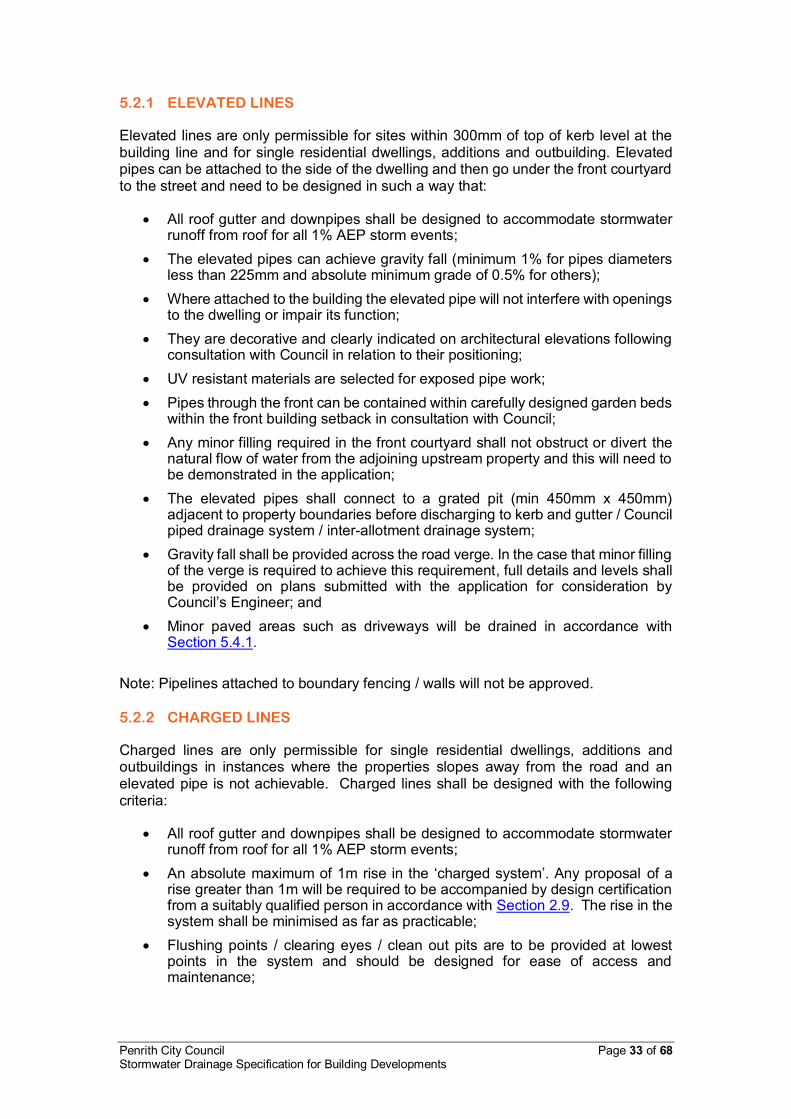
Penrith City Council Page 33 of 68 Stormwater Drainage Specification for Building Developments
5.2.1 ELEVATED LINES
Elevated lines are only permissible for sites within 300mm of top of kerb level at the building line and for single residential dwellings, additions and outbuilding. Elevated pipes can be attached to the side of the dwelling and then go under the front courtyard to the street and need to be designed in such a way that:
All roof gutter and downpipes shall be designed to accommodate stormwater runoff from roof for all 1% AEP storm events;
The elevated pipes can achieve gravity fall (minimum 1% for pipes diameters less than 225mm and absolute minimum grade of 0.5% for others);
Where attached to the building the elevated pipe will not interfere with openings to the dwelling or impair its function;
They are decorative and clearly indicated on architectural elevations following consultation with Council in relation to their positioning;
UV resistant materials are selected for exposed pipe work; Pipes through the front can be contained within carefully designed garden beds
within the front building setback in consultation with Council; Any minor filling required in the front courtyard shall not obstruct or divert the
natural flow of water from the adjoining upstream property and this will need to be demonstrated in the application;
The elevated pipes shall connect to a grated pit (min 450mm x 450mm) adjacent to property boundaries before discharging to kerb and gutter / Council piped drainage system / inter-allotment drainage system;
Gravity fall shall be provided across the road verge. In the case that minor filling of the verge is required to achieve this requirement, full details and levels shall be provided on plans submitted with the application for consideration by Council’s Engineer; and
Minor paved areas such as driveways will be drained in accordance with Section 5.4.1.
Note: Pipelines attached to boundary fencing / walls will not be approved. 5.2.2 CHARGED LINES
Charged lines are only permissible for single residential dwellings, additions and outbuildings in instances where the properties slopes away from the road and an elevated pipe is not achievable. Charged lines shall be designed with the following criteria:
All roof gutter and downpipes shall be designed to accommodate stormwater runoff from roof for all 1% AEP storm events;
An absolute maximum of 1m rise in the ‘charged system’. Any proposal of a rise greater than 1m will be required to be accompanied by design certification from a suitably qualified person in accordance with Section 2.9. The rise in the system shall be minimised as far as practicable;
Flushing points / clearing eyes / clean out pits are to be provided at lowest points in the system and should be designed for ease of access and maintenance;

Penrith City Council Page 34 of 68 Stormwater Drainage Specification for Building Developments
The low points in the charged system shall provide for a slow leak directed to an absorption trench to ensure stormwater is not permanently held in the drainage line;
The charged lines shall connect to a grated pit (min 450mm x 450mm) adjacent to property boundaries before discharging to kerb and gutter / Council piped drainage system / inter-allotment drainage system;
All pipes and downpipes shall be sealed to a minimum of 0.5m above the invert level of the street gutter / top water level in the system;
Gutter guards shall be installed on all gutters to minimize debris from entering the system;
Gravity fall shall be provided across the road verge. In the case that minor filling of the verge is required to achieve this requirement full details and levels shall be provided on plans submitted with the application for consideration by Council’s Engineer; and
Minor paved areas such as driveways will drained in accordance with Section 5.4.1.
5.3 RURAL DWELLINGS, ADDITIONS AND OUTBUILDINGS
Generally rural properties have no formal drainage system. To minimise the impact of stormwater runoff from these properties rainwater tanks are mandatory and must be sized in accordance with the following criteria: Table 12 Minimum Rainwater Tank Size
Area of roof and hardstand areas (excluding access driveway)
Minimum rainwater tank size (L)(1)
≤ 500sqm 10,000
> 500sqm and ≤ 1000sqm 20,000 >1000sqm 30,000
Notes: (1) Maximum tank sizes apply to land zoned E3 or E4 in accordance with Section C3.8 of Development Control Plan 2014. Rainwater tanks shall be designed in accordance with the principles of Section C3.8 Rainwater / Storage Tanks of Council’s Development Control Plan 2014. The location, sizing and levels of rainwater tanks shall be clearly indicated on the SCP. The SCP shall be prepared to ensure that there is no adverse impact to the subject property or to those downstream. In addition the following criteria for drainage of rural dwellings and associated structures shall be met:
Stormwater discharge shall be directed to the natural catchment; No discharge shall be within 10m of any septic disposal area, building or
property boundary; Discharge to a dam or natural watercourse shall comply with the
requirements of the NSW Office of Water. Discharge to land shall be by a suitably designed level spreader or absorption
system; Outlet protection and energy dissipaters shall be designed to reduce
velocities below 2m/s; and

Penrith City Council Page 35 of 68 Stormwater Drainage Specification for Building Developments
The outlet shall meet the requirements of the NSW Office of Water and where appropriate the NSW Department of Housing publication “Managing Urban Stormwater – Soils and Construction.
5.4 FOR MINOR AREAS - ACCEPTABLE DRAINAGE
METHODS
5.4.1 ABSORPTION TRENCHES
Absorption trenches are only permissible under following circumstances:
a) In urban areas for driveways, paths and minor paved areas of less than 50m2 etc., where an elevated lines or charged has been provided for the site.
b) In rural areas in application of Section 5.3.
The design and size of the absorption trench shall be determined by the following means:
Sized at the rate of 2000L/50 m2; Designed to allow full infiltration into an aggregate layer beneath; Sediment / rubbish entrapment within gutters and first flush system to prevent
foreign materials entering shall be incorporated into the design to prevent these materials compromising the absorption trench;
Trenching shall be located parallel to site contours; and The absorption trench shall be located as far as possible from the downstream
property boundary and buildings. Absorption trenches may be provided by suitable proprietary products or aggregate trenches where void ratios have been determined.

Penrith City Council Page 36 of 68 Stormwater Drainage Specification for Building Developments
6. INFORMATION AVAILABLE FROM COUNCIL AND AUTHORITIES
6.1 CATCHMENT INFORMATION
Catchment and pipe network information can be obtained from the following sources: 6.1.1 CONTOUR MAPS
Contour maps at a 0.5m interval can be purchased from Council. The contours can be overlayed on aerial photography and cadastral information. For further information, contact Council’s Information Management & Technology Department (02) 4732 7777. 6.1.2 TOPOGRAPHIC MAPS
NSW Land and Property Information (LPI) can provide a large range of topographic maps. Further information can be obtained by contacting LPI or visiting their website. 6.1.3 PIPED STORMWATER DRAINAGE NETWORK
Details of Council’s drainage network may be available. For further information, please contact Council’s Engineering Services Department on (02) 4732 7777. Any information that Council provides is indicative only and must be validated on site by appropriate investigation and survey. 6.2 FLOW RATES AND CONSULTANT REPORTS
Information relating to drainage schemes, consultants reports, flow rates and other relevant information where available can be provided by Council’s Engineering Services Department. This information will generally be provided as part of Council’s formal Pre-Lodgement advice service. 6.3 FLOOD INFORMATION
Over the years, Council and relevant state agencies have undertaken number of flood studies and flood assessment reports for various parts of our City. Currently, Council has adopted the following flood studies:
South Creek Flood Study (adopted on 24 November 2014)
Penrith Central Business District (CBD) Catchment Overland Flow Flood Study (adopted on 25 May 2015)
St Marys (Byrnes Creek) Catchment Overland Flow Study (adopted on 26 October 2015)
Information of these flood studies can be found from Council’s website. https://www.penrithcity.nsw.gov.au/Services/Other-Services/Floodplain-Management/

Penrith City Council Page 37 of 68 Stormwater Drainage Specification for Building Developments
In addition, Council is in the process of undertaking mainstream flood study of the Nepean River and a broad scale local flooding study over the LGA. Upon completion of these studies and adoption by Council, further information will be available to the Council’s customers. A Flood Level Enquiry or Flood Report are currently available for purchase from Council’s Engineering Services Department. An application can be made by completing the application form on Council’s website. https://www.penrithcity.nsw.gov.au/Documents/Building-and-Development/Flood-Information-Application-Form/ 6.3.1 FLOOD LEVEL ENQUIRY
A flood level enquiry provides the 1% AEP (Annual Exceedance Probability) flood level for the property in metres AHD (Australian Height Datum) and aerial photography of the property with contours. Local overland flow extents are provided where a study has been completed. 6.3.2 FLOOD REPORT
A flood report contains the information in a flood level enquiry as well as surveyed ground levels at the corner of the property and the floor level of the main building on the property. It also provides a brief commentary of flooding on the property. 6.4 SECTION 10.7 CERTIFICATE (PREVIOUSLY S149)
A Section 10.7 Certificate notates possible affectations relating to a property including flooding, overland flow and other site constraints that may require investigation. A Section 10.7 Certificate can be purchased from Council’s Planning Information Unit on (02) 4732 7777. 6.5 SERVICES LOCATION
Information regarding the location of services can be obtained from Dial Before You Dig. For further information contact Dial Before You Dig or visit their website. 6.6 COUNCIL’S PLANNING CONTROLS AND POLICIES
Any Council document referred to in this policy is available from Council’s website. Council’s customer service team can be contacted for further information on (02) 4732 7777.

Penrith City Council Page 38 of 68 Stormwater Drainage Specification for Building Developments
7. APPENDICES
APPENDIX A CHECKLIST FOR STORMWATER CONCEPT PLAN (SCP)
Survey Information Yes No NA
1. Site boundaries
2. North point
3. Services within the public footway
4. Site features, including tree, structures, depressions 5. Contours at 0.1m for flat sites ranging to 0.5m for steep
sites and extending 10m into adjoining properties
6. Top of kerb levels
7. Boundary levels
8. Benchmarks 9. Levels to AHD where site is affected by overland flow,
flooding or where works on Council’s drainage network are required
General Yes No NA
1. Plans to scale of 1:100 or 1:200
2. Designer’s name, qualifications, contact details provided 3. Design report, including details of any variations
provided
4. Plan number and date of issue shown 5. Consistency between stormwater, architectural and
landscape plans
6. 1% AEP overland flow extents shown 7. Development layout, building envelope and proposed
driveway locations shown
8. Drainage calculations to support the proposed design submitted
9. Proposed finished floor, garage and ground surface levels shown

Penrith City Council Page 39 of 68 Stormwater Drainage Specification for Building Developments
10. Compliance with freeboard requirements
11. Location and level of proposed retaining walls indicated
12. Appropriate tail water selected 13. No adverse impact on other properties or the stormwater
network
14. Mainstream flood / local overland flow flood report (if any)
Drainage Layout Yes No NA
1. Pipe size, grade and invert level indicated
2. Pit location, size, invert level and surface level indicated
3. Proposed connection point to Council’s stormwater system
OSD Yes No NA 1. A catchment plan showing areas draining to the OSD
system.
2. Location and size of OSD system and WSUD measures shown
3. Location and level of OSD discharge points shown
4. Compliance with detention volume required
5. Compliance with less than 15% of site area bypassing OSD system
6. Compliance with the Permissible Site Discharge (PSD) requirements
7. Compliance with OSD storage depths
8. Overland flows clear from the OSD system
9. OSD storage located within common areas, clear of private courtyards and accessible from the street
10. Overflow weir provided and shown
11. Details of discharge control pit shown
12. Orifice details and calculations shown
13. Typical sections of OSD storage, including basin invert level, centreline level of outlet orifice, top water level, finished surface levels provided
14. Provision of design certification of the OSD system in accordance with this policy

Penrith City Council Page 40 of 68 Stormwater Drainage Specification for Building Developments
Others
Yes No NA
1. Location of Council’s drainage easements, private inter-allotment easements shown (if any)
2. Location and details of basement pump-out system provided (if any)
3. Location and details of overland flow path shown (if any)

Penrith City Council Page 41 of 68 Stormwater Drainage Specification for Building Developments
APPENDIX B CHECKLIST FOR CONSTRUCTION CERTIFICATE
General
Yes No NA
1. Plans are in general accordance with the SCP approved with the development consent
2. Plans have addressed all relevant conditions of development consent
3. Plans have sufficient survey and design information as described in the checklist for the Stormwater Concept Plan in Appendix A of Council’s Stormwater Drainage Specification for Building Developments
4. Plans have full details and specifications for construction and to demonstrate that the proposal is satisfactory
5. Detailed design report including hydrologic and hydraulic calculations including all input parameters and assumptions
6. The OSD system has been designed in accordance with this policy, Australian Rainfall and Runoff, AS/NZS 3500.3 and relevant Australian Standards
7. Structural design certificate has been submitted for OSD tanks, retaining walls in excess of 600mm and any other structures
8. Compliance Certificate (under Part 4A of Environmental Planning and Assessment Act 1979) has been issued by Category C3 Accredited Certifier - stormwater management facilities design compliance

Penrith City Council Page 42 of 68 Stormwater Drainage Specification for Building Developments
APPENDIX C CHECKLIST FOR OCCUPATION CERTIFICATE
General
Yes No NA
1. Works-As-Executed plans, in accordance with this policy, have been prepared by a registered surveyor
2. The constructed works are in accordance with the Construction Certificate drawings and specifications and relevant conditions of consent
3. Structural construction certification of OSD tanks, retaining walls in excess of 600mm and any other structures has been provided in accordance with this policy
4. The works as constructed will not have adverse impact on other properties or the stormwater network
5. Restrictions on Use of Land, positive covenants and / or easements have been registered on the property title where required
OSD
Yes No NA
1. The OSD system has been constructed to the tolerances listed within this policy and any variations from the approved design will not impair the performance of the OSD system.
2. A copy of the OSD maintenance schedule has been prepared and a copy forwarded to Council
3. A Restriction on the Use of Land and Positive Covenant for the OSD system has been registered on the property title
4. Compliance Certificate (under Part 4A of Environmental Planning and Assessment Act 1979) has been issued by:
Category C4 Accredited Certifier - stormwater management construction compliance
Category C15 Accredited Certifier - stormwater compliance
5. A copy of the above documents must be provided to Council with any notification of issue of an Occupation Certificate.

Penrith City Council Page 43 of 68 Stormwater Drainage Specification for Building Developments
APPENDIX D ON-SITE DETENTION AREA - PENRITH CBD
Not to Scale

Penrith City Council Page 44 of 68 Stormwater Drainage Specification for Building Developments
ON-SITE DETENTION AREA - PENRITH NORTH
Not to Scale

Penrith City Council Page 45 of 68 Stormwater Drainage Specification for Building Developments
ON-SITE DETENTION AREA - LEMONGROVE
Not to Scale

Penrith City Council Page 46 of 68 Stormwater Drainage Specification for Building Developments
ON-SITE DETENTION AREA - EMU PLAINS (NORTH)
Not to Scale

Penrith City Council Page 47 of 68 Stormwater Drainage Specification for Building Developments
ON-SITE DETENTION AREA - EMU PLAINS (WEST)
Not to Scale

Penrith City Council Page 48 of 68 Stormwater Drainage Specification for Building Developments
ON-SITE DETENTION AREA - JAMISONTOWN
Not to Scale

Penrith City Council Page 49 of 68 Stormwater Drainage Specification for Building Developments
ON-SITE DETENTION AREA - ST MARYS (EAST)
Not to Scale

Penrith City Council Page 50 of 68 Stormwater Drainage Specification for Building Developments
ON-SITE DETENTION AREA - ST MARYS (WEST)
Not to Scale

Penrith City Council Page 51 of 68 Stormwater Drainage Specification for Building Developments
ON-SITE DETENTION AREA - COLYTON
Not to Scale

Penrith City Council Page 52 of 68 Stormwater Drainage Specification for Building Developments
ON-SITE DETENTION AREA - OXLEY PARK
Not to Scale

Penrith City Council Page 53 of 68 Stormwater Drainage Specification for Building Developments
ON-SITE DETENTION AREA - DUNHEVED & WERRINGTON
Not to Scale

Penrith City Council Page 54 of 68 Stormwater Drainage Specification for Building Developments
ON-SITE DETENTION AREA - KINGSWOOD & ORCHARD HILLS
Not to Scale

Penrith City Council Page 55 of 68 Stormwater Drainage Specification for Building Developments
ON-SITE DETENTION AREA - CAMBRIDGE PARK
Not to Scale
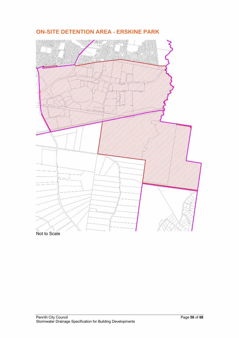
Penrith City Council Page 56 of 68 Stormwater Drainage Specification for Building Developments
ON-SITE DETENTION AREA - ERSKINE PARK
Not to Scale

Penrith City Council Page 57 of 68 Stormwater Drainage Specification for Building Developments
APPENDIX E RAINFALL INTENSITY COEFFICIENTS FOR PENRITH
List of coefficients to equations of the form: (from Bureau of Meteorology) ln(I) = a + b(ln(T)) + c(ln(T))2 + d(ln(T))3 + e(ln(T))4 + f(ln(T))5 + g(ln(T))6
Where I = Intensity in millimetres per hour; and
T = Time in hours Location: Nepean Hospital
Return Period (year)
A B C D E F G
1 3.1259 -0.5804 -0.02132 0.009603 -0.001117 -0.0005020 0.0000716 2 3.3837 -0.5806 -0.02188 0.009313 -0.000975 -0.0004565 0.0000635 5 3.6477 -0.5805 -0.02448 0.007651 -0.000199 -0.0002151 0.0000037 10 3.7766 -0.5815 -0.02574 0.007366 0.000129 -0.0001535 -0.0000152 20 3.9240 -0.5816 -0.02700 0.006886 0.000444 -0.0000841 -0.0000338 50 4.0902 -0.5816 -0.02832 0.006092 0.000848 0.0000395 -0.0000656
100 4.2015 -0.5819 -0.02893 0.005747 0.001033 0.0000933 -0.0000785 DESIGN RAINFALL INTESNSITY FOR PENRITH
Annual Exceedance Probability (AEP) Duration Hr Min
100% (mm/h)
50% (mm/h)
20% (mm/h)
10% (mm/h)
5% (mm/h)
2% (mm/h)
1% (mm/h)
0 5 74.51 96.49 125.86 143.36 166.29 196.42 219.79 0 6 69.67 90.24 117.91 134.33 155.84 184.27 206.25 0 7 65.72 85.12 111.26 126.75 147.02 173.89 194.63 0 8 62.38 80.79 105.57 120.25 139.45 164.94 184.59 0 9 59.49 77.04 100.63 114.60 132.87 157.12 175.82 0 10 56.95 73.75 96.27 109.62 127.08 150.23 168.09 0 11 54.69 70.81 92.39 105.19 121.92 144.10 161.21 0 12 52.66 68.18 88.91 101.22 117.29 138.61 155.04 0 13 50.82 65.79 85.76 97.62 113.11 133.64 149.46 0 14 49.14 63.61 82.89 94.35 109.31 129.12 144.40 0 15 47.60 61.61 80.26 91.35 105.83 125.00 139.77 0 16 46.18 59.77 77.85 88.59 102.63 121.20 135.52 0 17 44.87 58.07 75.61 86.05 99.68 117.70 131.60 0 18 43.65 56.49 73.54 83.69 96.94 114.46 127.97 0 19 42.51 55.01 71.61 81.49 94.39 111.44 124.59 0 20 41.45 53.63 69.81 79.43 92.01 108.63 121.44 0 22 39.51 51.13 66.53 75.71 87.70 103.52 115.73 0 24 37.79 48.90 63.63 72.40 83.87 99.01 110.67 0 26 36.25 46.91 61.04 69.45 80.45 94.97 106.16 0 28 34.86 45.11 58.70 66.79 77.38 91.34 102.10 0 30 33.60 43.48 56.58 64.38 74.59 88.05 98.42 0 35 30.91 39.99 52.05 59.23 68.62 81.01 90.55 0 40 28.71 37.15 48.35 55.01 63.75 75.26 84.13 0 45 26.87 34.77 45.26 51.50 59.68 70.46 78.76 0 50 25.30 32.74 42.63 48.51 56.21 66.37 74.19 0 55 23.96 31.00 40.37 45.92 53.22 62.84 70.24 1 00 22.78 29.48 38.38 43.67 50.60 59.75 66.79
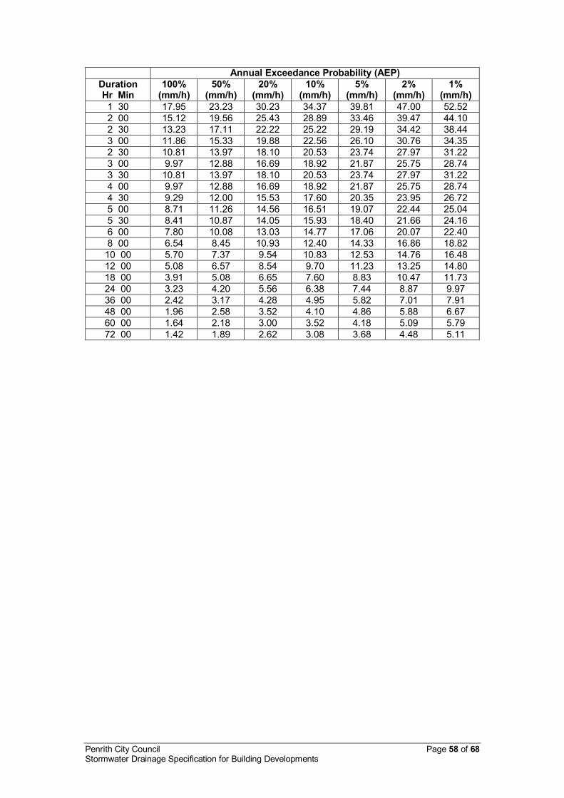
Penrith City Council Page 58 of 68 Stormwater Drainage Specification for Building Developments
Annual Exceedance Probability (AEP) Duration Hr Min
100% (mm/h)
50% (mm/h)
20% (mm/h)
10% (mm/h)
5% (mm/h)
2% (mm/h)
1% (mm/h)
1 30 17.95 23.23 30.23 34.37 39.81 47.00 52.52 2 00 15.12 19.56 25.43 28.89 33.46 39.47 44.10 2 30 13.23 17.11 22.22 25.22 29.19 34.42 38.44 3 00 11.86 15.33 19.88 22.56 26.10 30.76 34.35 2 30 10.81 13.97 18.10 20.53 23.74 27.97 31.22 3 00 9.97 12.88 16.69 18.92 21.87 25.75 28.74 3 30 10.81 13.97 18.10 20.53 23.74 27.97 31.22 4 00 9.97 12.88 16.69 18.92 21.87 25.75 28.74 4 30 9.29 12.00 15.53 17.60 20.35 23.95 26.72 5 00 8.71 11.26 14.56 16.51 19.07 22.44 25.04 5 30 8.41 10.87 14.05 15.93 18.40 21.66 24.16 6 00 7.80 10.08 13.03 14.77 17.06 20.07 22.40 8 00 6.54 8.45 10.93 12.40 14.33 16.86 18.82
10 00 5.70 7.37 9.54 10.83 12.53 14.76 16.48 12 00 5.08 6.57 8.54 9.70 11.23 13.25 14.80 18 00 3.91 5.08 6.65 7.60 8.83 10.47 11.73 24 00 3.23 4.20 5.56 6.38 7.44 8.87 9.97 36 00 2.42 3.17 4.28 4.95 5.82 7.01 7.91 48 00 1.96 2.58 3.52 4.10 4.86 5.88 6.67 60 00 1.64 2.18 3.00 3.52 4.18 5.09 5.79 72 00 1.42 1.89 2.62 3.08 3.68 4.48 5.11

Penrith City Council Page 59 of 68 Stormwater Drainage Specification for Building Developments
APPENDIX F STANDARD TERMS FOR RESTRICTIONS ON THE USE OF LAND AND POSITIVE COVENANTS
OVERLAND FLOW
Restriction on the Use of Land The registered proprietor of the burdened lot shall not: (a) Erect, construct or place any building or structure,
(b) Make alterations to the ground surface levels, grates, pipes, pits, drains,
walls, tanks, chambers, basins or any other structure associated with the overland flow path,
(c) Erect any fencing, including boundary fencing, unless such fencing is of
open style which will not obstruct the flow of water across the land, within the land so burdened without the prior written consent of Penrith City Council.
Positive Covenant
(1) The registered proprietor of the burdened lot from time to time shall do all things necessary to maintain, repair and replace the surfaces grates, pipes, pits, drains, walls, tanks, chambers, basins or any other structures of and incidental to the overland flow path within the land so burdened to the satisfaction of Penrith City Council and in this regard must also comply with any reasonable written request of the Council within such time period nominated.
(2) Where the registered proprietor of the burdened lots fails to comply with
any written request of the Penrith City Council referred to in (1) above the registered proprietor shall meet any reasonable cost incurred by the Council in completing the work requested.
(3) Full and free right for the Penrith City Council and every person
authorised by it to enter upon the burdened lot in order to inspect, maintain, cleanse, replace, repair any grates, pipes, pits, drains, walls, tanks, chambers, basins or any other structure or alter surface levels to ensure the overland flow path within the land so burdened functions in accordance with the approved Construction Certificate (Council Reference: DA / ).
Please note: Penrith City Council must be nominated as the authority whose consent is required to release, vary or modify the above restriction and positive covenant.
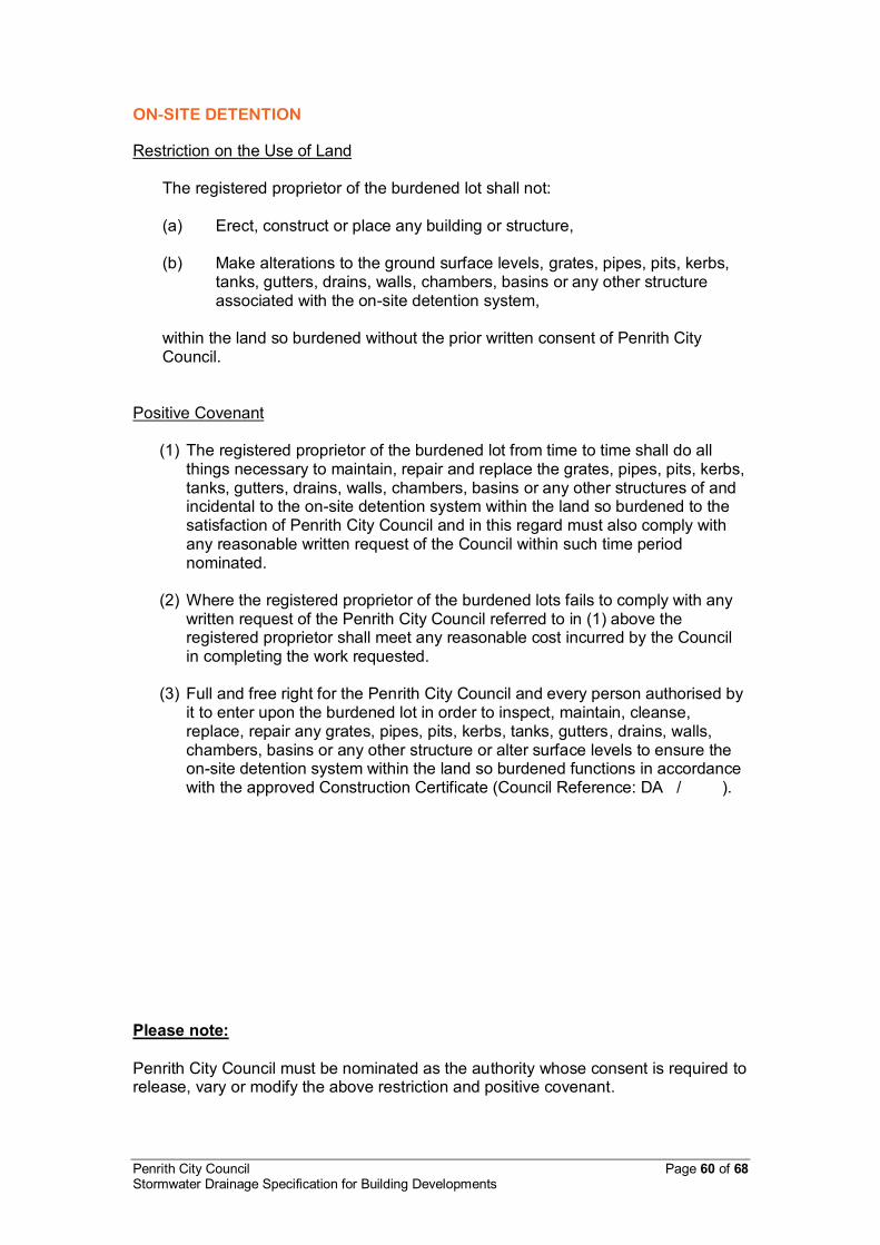
Penrith City Council Page 60 of 68 Stormwater Drainage Specification for Building Developments
ON-SITE DETENTION
Restriction on the Use of Land
The registered proprietor of the burdened lot shall not: (a) Erect, construct or place any building or structure,
(b) Make alterations to the ground surface levels, grates, pipes, pits, kerbs,
tanks, gutters, drains, walls, chambers, basins or any other structure associated with the on-site detention system,
within the land so burdened without the prior written consent of Penrith City Council.
Positive Covenant
(1) The registered proprietor of the burdened lot from time to time shall do all things necessary to maintain, repair and replace the grates, pipes, pits, kerbs, tanks, gutters, drains, walls, chambers, basins or any other structures of and incidental to the on-site detention system within the land so burdened to the satisfaction of Penrith City Council and in this regard must also comply with any reasonable written request of the Council within such time period nominated.
(2) Where the registered proprietor of the burdened lots fails to comply with any
written request of the Penrith City Council referred to in (1) above the registered proprietor shall meet any reasonable cost incurred by the Council in completing the work requested.
(3) Full and free right for the Penrith City Council and every person authorised by
it to enter upon the burdened lot in order to inspect, maintain, cleanse, replace, repair any grates, pipes, pits, kerbs, tanks, gutters, drains, walls, chambers, basins or any other structure or alter surface levels to ensure the on-site detention system within the land so burdened functions in accordance with the approved Construction Certificate (Council Reference: DA / ).
Please note: Penrith City Council must be nominated as the authority whose consent is required to release, vary or modify the above restriction and positive covenant.

Penrith City Council Page 61 of 68 Stormwater Drainage Specification for Building Developments
BASEMENT PUMP-OUT SYSTEM
Restriction on the Use of Land
The registered proprietor of the burdened lot shall not: (a) Erect, construct or place any building or structure,
(b) Make alterations to the pumps, surface levels, grates, pipes, pits, kerbs,
tanks, gutters, drains, walls, chambers or any other structure associated with the basement pump-out system,
Within the land so burdened without the prior written consent of Penrith City Council.
Positive Covenant
(1) The registered proprietor of the burdened lot from time to time shall do all things necessary to maintain, repair and replace the pumps, grates, pipes, pits, kerbs, tanks, gutters, drains, walls, chambers or any other structures of and incidental to the basement pump-out system within the land so burdened to the satisfaction of Penrith City Council and in this regard must also comply with any reasonable written request of the Council within such time period nominated.
(2) Where the registered proprietor of the burdened lots fails to comply with any
written request of the Penrith City Council referred to in (1) above the registered proprietor shall meet any reasonable cost incurred by the Council in completing the work requested.
(3) Full and free right for the Penrith City Council and every person authorised by
it to enter upon the burdened lot in order to inspect, maintain, cleanse, replace, repair any pumps, grates, pipes, pits, kerbs, tanks, gutters, drains, walls, chambers or any other structure or alter surface levels to ensure the basement pump-out system within the land so burdened functions in accordance with the approved Construction Certificate (Council Reference: DA / ).
Please note: Penrith City Council must be nominated as the authority whose consent is required to release, vary or modify the above restriction and positive covenant.
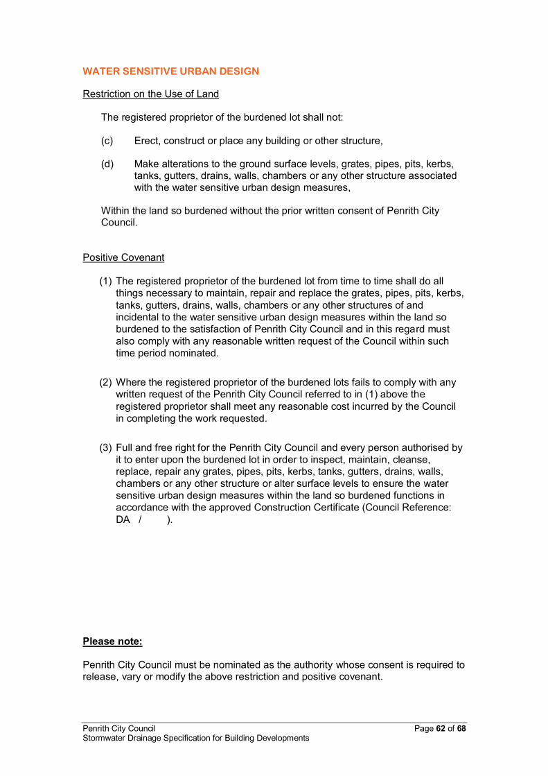
Penrith City Council Page 62 of 68 Stormwater Drainage Specification for Building Developments
WATER SENSITIVE URBAN DESIGN
Restriction on the Use of Land
The registered proprietor of the burdened lot shall not: (c) Erect, construct or place any building or other structure,
(d) Make alterations to the ground surface levels, grates, pipes, pits, kerbs,
tanks, gutters, drains, walls, chambers or any other structure associated with the water sensitive urban design measures,
Within the land so burdened without the prior written consent of Penrith City Council.
Positive Covenant (1) The registered proprietor of the burdened lot from time to time shall do all
things necessary to maintain, repair and replace the grates, pipes, pits, kerbs, tanks, gutters, drains, walls, chambers or any other structures of and incidental to the water sensitive urban design measures within the land so burdened to the satisfaction of Penrith City Council and in this regard must also comply with any reasonable written request of the Council within such time period nominated.
(2) Where the registered proprietor of the burdened lots fails to comply with any
written request of the Penrith City Council referred to in (1) above the registered proprietor shall meet any reasonable cost incurred by the Council in completing the work requested.
(3) Full and free right for the Penrith City Council and every person authorised by
it to enter upon the burdened lot in order to inspect, maintain, cleanse, replace, repair any grates, pipes, pits, kerbs, tanks, gutters, drains, walls, chambers or any other structure or alter surface levels to ensure the water sensitive urban design measures within the land so burdened functions in accordance with the approved Construction Certificate (Council Reference: DA / ).
Please note: Penrith City Council must be nominated as the authority whose consent is required to release, vary or modify the above restriction and positive covenant.

Penrith City Council Page 63 of 68 Stormwater Drainage Specification for Building Developments
APPENDIX G DEFINITIONS / ABBREVIATIONS
Accredited Certifier Person who holds a certificate of accreditation as an accredited certifier under the Building Professionals Act 2005.
Applicant The person/s, company or entity who have the
benefit of the development consent for the purpose of constructing the Works.
AR&R Australian Rainfall and Runoff AEP Annual Exceedance Probability AS Australian Standards published by the
Standards Association of Australia and being current at the time of application.
Council Penrith City Council as represented by its
employees. Council’s Engineer Person approving or inspecting works as a
delegate of the Council. Designer Person appointed by Project Manager to
undertake the design who is practicing and has appropriate experience and qualification.
Developer Person with the benefit of and acting on the Development Consent.
Development Consent Notice of Determination driving Subdivision
or Development Approval subject to conditions.
EP&A Act Environmental Planning and Assessment Act
1979, as amended. HGL Hydraulic Grade Line OSD On-Site Stormwater Detention. Principal Certifying Authority The consent authority, the Council, or
accredited certifier appointed (for building or subdivision work to be carried out on a site) to carry out functions as described in s109E of the EP&A Act.
PSD Permissible Site Discharge

Penrith City Council Page 64 of 68 Stormwater Drainage Specification for Building Developments
SCP Stormwater Concept Plan Site Area of land being developed under the
Subdivision or Development Approval. SSR Site Storage Requirement. Surveyor Surveyor registered under the Surveying and
Spatial Information Act 2002. uPVC unplasticised Polyvinyl Chloride (referring to
pipe). WAE Works as Executed Plan. Works The development of land as described by the
Development Consent and drawings and specifications (the Documents) as proposed by the Applicant and as cited and approved by Council "For Construction" including all the area of the land being developed.
WSUD Water Sensitive Urban Design.

Penrith City Council Page 65 of 68 Stormwater Drainage Specification for Building Developments
APPENDIX H STANDARD DRAWINGS
SD3001 OSD TYPICAL DISCHARGE CONTROL PIT SD3002 TYPICAL ON-SITE DETENTION IN DRIVEWAY AREAS SD3003 TYPICAL ON-SITE DETENTION IN LANDSCAPED AREAS

Penrith City Council Page 66 of 68 Stormwater Drainage Specification for Building Developments

Penrith City Council Page 67 of 68 Stormwater Drainage Specification for Building Developments

Penrith City Council Page 68 of 68 Stormwater Drainage Specification for Building Developments