Policy Control Function Cloud Native User's Guide€¦ · Policy Control Function Cloud Native...
39
Oracle® Communications Policy Control Function Cloud Native User's Guide Release 1.0 F16914-01 April 2019
Transcript of Policy Control Function Cloud Native User's Guide€¦ · Policy Control Function Cloud Native...

Oracle® Communications Policy Control Function Cloud Native User's Guide
Release 1.0 F16914-01 April 2019

Oracle Communications Policy Control Function Cloud Native User's Guide, Release 1.0
F16914-01
Copyright © 2019, Oracle and/or its affiliates. All rights reserved.
This software and related documentation are provided under a license agreement containing restrictions on use and disclosure and are protected by intellectual property laws. Except as expressly permitted in your license agreement or allowed by law, you may not use, copy, reproduce, translate, broadcast, modify, license, transmit, distribute, exhibit, perform, publish, or display any part, in any form, or by any means. Reverse engineering, disassembly, or decompilation of this software, unless required by law for interoperability, is prohibited.
The information contained herein is subject to change without notice and is not warranted to be error-free. If you find any errors, please report them to us in writing.
If this is software or related documentation that is delivered to the U.S. Government or anyone licensing it on behalf of the U.S. Government, then the following notice is applicable:
U.S. GOVERNMENT END USERS: Oracle programs, including any operating system, integrated software, any programs installed on the hardware, and/or documentation, delivered to U.S. Government end users are "commercial computer software" pursuant to the applicable Federal Acquisition Regulation and agency-specific supplemental regulations. As such, use, duplication, disclosure, modification, and adaptation of the programs, including any operating system, integrated software, any programs installed on the hardware, and/or documentation, shall be subject to license terms and license restrictions applicable to the programs. No other rights are granted to the U.S. Government.
This software or hardware is developed for general use in a variety of information management applications. It is not developed or intended for use in any inherently dangerous applications, including applications that may create a risk of personal injury. If you use this software or hardware in dangerous applications, then you shall be responsible to take all appropriate fail-safe, backup, redundancy, and other measures to ensure its safe use. Oracle Corporation and its affiliates disclaim any liability for any damages caused by use of this software or hardware in dangerous applications.
Oracle and Java are registered trademarks of Oracle and/or its affiliates. Other names may be trademarks of their respective owners.
Intel and Intel Xeon are trademarks or registered trademarks of Intel Corporation. All SPARC trademarks are used under license and are trademarks or registered trademarks of SPARC International, Inc. AMD, Opteron, the AMD logo, and the AMD Opteron logo are trademarks or registered trademarks of Advanced Micro Devices. UNIX is a registered trademark of The Open Group.
This software or hardware and documentation may provide access to or information about content, products, and services from third parties. Oracle Corporation and its affiliates are not responsible for and expressly disclaim all warranties of any kind with respect to third-party content, products, and services unless otherwise set forth in an applicable agreement between you and Oracle. Oracle Corporation and its affiliates will not be responsible for any loss, costs, or damages incurred due to your access to or use of third-party content, products, or services, except as set forth in an applicable agreement between you and Oracle.

3
Contents 1 Introduction
Overview 1-1 Acronyms 1-1 References 1-3
2 Policy Control Function Architecture
3 About Policy Design Experience
4 About Policy Control Function Services About Session Management Service 4-1
Configuring Session Management Service 4-1 About Access and Mobility Service 4-7
Configuring Access and Mobility Service 4-7
5 Configuring Policy Control Function Configuring NRF Client Service 5-1 Configuring Session Rule Service 5-1 Managing Session Rule Profile 5-2 Managing Service Area Restriction 5-3 Managing Authorized Default Qos 5-3 Managing PCC Rule 5-4 Managing PCC Rule Profile 5-6 Managing QoS Data 5-7 Managing Charging Data 5-8 Managing Usage Monitoring Data 5-10 Managing Traffic Control Data 5-11 Managing Condition Data 5-12 Viewing Sessions 5-13 Configuring Match List 5-13

4
6 Managing Policy Managing Policy Projects 6-1
7 Administering Policy Control Function Managing Users 7-1 Managing Roles 7-1 Managing Data Model 7-2 Managing Dynamic Configuration Menu Demo 7-3
List of Figures
2-1 PCF Architecture 2-2
3-1 Policy Design Experience 3-1
List of Tables
1-1 Acronyms 1-1
4-1 Session Management Service Fields 4-1
4-2 Access and Mobility Service Fields 4-7
5-1 NRF Client Services Resources 5-1
5-2 Flow Info Fields 5-5
1-1
1 Introduction
This document provides information on how to use the Policy Control Function and configure the services.
Overview The Oracle Communications Policy Management solution is enhanced to add Policy Control Function that extends the functionality of PCRF as part of 5G core network. The Policy Control Function is a functional element for policy control decision and flows based charging control functionalities. The PCF provides the following functions:
• Policy rules for application and service data flow detection, gating, QoS, and flow based charging to the SMF.
• Access and Mobility Management related policies to the AMF.
Acronyms Table 1-1 provides information about the acronyms used in the document.
Table 1-1 Acronyms
Acronym Definition
5GC 5G Core Network 5GS 5G System 5G-AN 5G Access Network 5G-EIR 5G-Equipment Identity Register 5G-GUTI 5G Globally Unique Temporary Identifier 5G-S-TMSI 5G S-Temporary Mobile Subscription Identifier 5QI 5G QoS Identifier AF Application Function AMF Access and Mobility Management Function AS Access Stratum AUSF Authentication Server Function BSF Binding Support Function CAPIF Common API Framework for 3GPP northbound
APIs CP Control Plane DL Downlink DN Data Network DNAI DN Access Identifier DNN Data Network Name DRX Discontinuous Reception

1-2
Chapter 1 Acronyms
Table 1-1 (Cont.) Acronyms
Acronym Definition
ePDG evolved Packet Data Gateway EBI EPS Bearer Identity FAR Forwarding Action Rule FQDN Fully Qualified Domain Name GFBR Guaranteed Flow Bit Rate GMLC Gateway Mobile Location Centre GPSI Generic Public Subscription Identifier GUAMI Globally Unique AMF Identifier HR Home Routed (roaming) LADN Local Area Data Network LBO Local Break Out (roaming) LMF Location Management Function LRF Location Retrieval Function MCX Mission Critical Service MDBV Maximum Data Burst Volume MFBR Maximum Flow Bit Rate MICO Mobile Initiated Connection Only MPS Multimedia Priority Service N3IWF Non-3GPP InterWorking Function NAI Network Access Identifier NEF Network Exposure Function NF Network Function NGAP Next Generation Application Protocol NR New Radio NRF Network Repository Function NSI ID Network Slice Instance Identifier NSSAI Network Slice Selection Assistance Information NSSF Network Slice Selection Function NSSP Network Slice Selection Policy NWDAF Network Data Analytics Function PCF Policy Control Function PDR Packet Detection Rule PEI Permanent Equipment Identifier PER Packet Error Rate PFD Packet Flow Description PPD Paging Policy Differentiation PPF Paging Proceed Flag PPI Paging Policy Indicator PSA PDU Session Anchor QFI QoS Flow Identifier QoE Quality of Experience (R)AN (Radio) Access Network RQA Reflective QoS Attribute

1-3
Chapter 1 References
Table 1-1 (Cont.) Acronyms
Acronym Definition
RQI Reflective QoS Indication SA NR Standalone New Radio SBA Service Based Architecture SBI Service Based Interface SD Slice Differentiator SEAF Security Anchor Functionality SEPP Security Edge Protection Proxy SMF Session Management Function SMSF Short Message Service Function S-NSSAI Single Network Slice Selection Assistance
Information SSC Session and Service Continuity SSCMSP Session and Service Continuity Mode Selection
Policy SST Slice/Service Type SUCI Subscription Concealed Identifier SUPI Subscription Permanent Identifier TNL Transport Network Layer TNLA Transport Network Layer Association TSP Traffic Steering Policy UDM Unified Data Management UDR Unified Data Repository UDSF Unstructured Data Storage Function UL Uplink UL CL Uplink Classifier UPF User Plane Function URSP UE Route Selection Policy VID VLAN Identifier VLAN Virtual Local Area Network
References User can refer to the following documents for information.
• Oracle Communications Policy Control Function Cloud Native User's Guide.
2
2-1
Policy Control Function Architecture
The Oracle Communications Policy Management solution is enhanced to add Policy Control Function that extends the functionality of PCRF as part of 5G core network. The Policy Control Function is a functional element for policy control decision and flows based charging control functionalities.
The PCF provides the following functions:
• Policy rules for application and service data flow detection, gating, QoS, and flow based charging to the SMF.
• Access and Mobility Management related policies to the AMF.
• Micro-services based Cloud-Native Architecture
• Policy Design Evolution to support modular and flexible Domain Driven Policy design
• Compliant with 3GPP Release 15 specifications
• Product supports Session Management, Access management and Authorization policy control services
• Flexible, user friendly Policy Design Framework for rapid policy use case deployments
• Pluggable Data Sources to ingest input from a variety of data sources (UDR, LDAP, Analytics, etc.)
• Support of different Deployment Options - PLMN level, slice shared and slice specific
The Oracle Communications Policy Control Function is built as a cloud-native application composed of a collection of microservices running in a cloud-native environment. It separates processing/business logic and state concerns following the corresponding logical grouping of microservices/components:

Chapter 2
2-2
Figure 2-1 PCF Architecture
• Connectivity: Components interfacing with external entities. This is where an API gateway is utilized to interface with external traffic to the PCF. These are stateless sets of components.
• Business logic: Application layer running the PCRF/PCF business logic, policy engine and various services that can be enabled based on deployment needs. These are stateless sets of components.
• Data Management: Data layer responsible for storing various types of persistent data. The PCF is built to be able to plug in different types of backend data layers that could be internal or external.
3
3-1
About Policy Design Experience
Policy design experience allows an operator to craft and deploy, from scratch, operator policies in production in very less time. 5G brings the policy design experience to the next level by providing flexibility, extensibility, modularization, and assurance to the operator to rapidly, yet confidently deploy new operator policies and enable use cases more faster.
The Policy Control Function packages its micro-services into containers and leverages Kubernetes' constructs and abstractions such as Pods, ReplicaSets, and services so it can enable Kubernetes to manage and orchestrate the PCF. It also leverages Istio as a service mesh (including Envoy proxies as sidecars) for the internal communication amongst the various micro-services. The Oracle PCF integrates with a variety of common services for data collection, analysis, and visualization services for operational aspects like logs, metrics, and traces. The Oracle 5GC PCF comprises artifacts like Helm charts that encapsulate lifecycle instructions and resource dependencies for all member components.
The Oracle PCF is flexible to run in various cloud-native environments. The Policy Control Function can be configured to leverage common services provided by the cloud-native environment and/or provide its own set if certain common services aren't provided by the underlying environment.
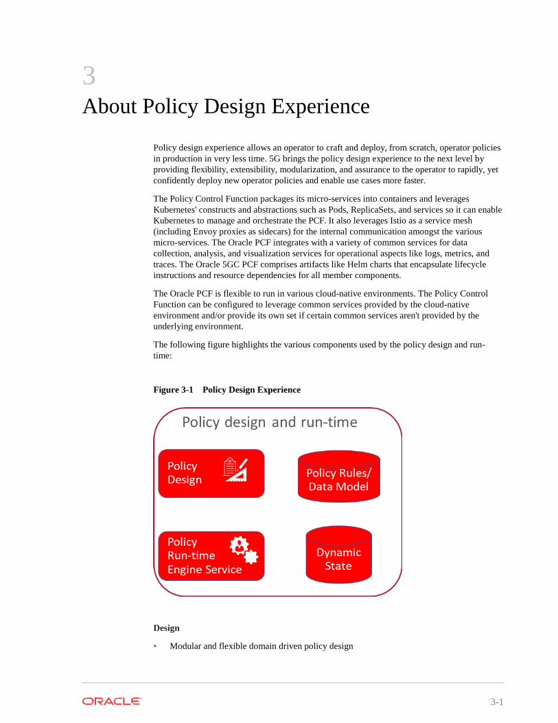
The following figure highlights the various components used by the policy design and run- time:
Figure 3-1 Policy Design Experience
Design
• Modular and flexible domain driven policy design

Chapter 3
3-2
• Modules encompasses data model, triggers, conditions and actions
• Modules can be designed via a GUI (very intuitive, can be used by anyone) and allows any language supported by JVM for advances cases if needed (e.g. Java, Groovy, etc)
• Pre-packaged modules provided by Oracle
• Modules can be extended or built by operators
Run-time
• Run-time engine service to expose APIs
• Run-time engine service to be stateless and independently scalable
• Newly designed policies or policy updates can be rolled out in an incremental fashion (e.g. to a specific set of policy run-time engines) to enable canary releases and ensure updates are working as expected before being rolled out globally
Debugging and testing
• Debugging policy logic capability as a complementary tool to the design experience
• Automated testing framework to enable regression and validation of policy logic and modules before deployment

4
4-1
About Policy Control Function Services
About Session Management Service PCF extends SM Policy service over the N7 interface for session management. Session management in 5G network is service equivalent to Gx interface in traditional EPC core.
Session management supports the following:
• PCC rule authorization
• QoS enforcement
• Subscriber-specific policy enforcement
For configuring session management service, see Configuring Session Management Service.
Configuring Session Management Service You can edit and refresh the session management service.
Table 4-1 Session Management Service Fields
Field Description
System Log level Component Tracing Server Root URL
Indicates the log level of PCF SM Service. Default Value: WARN Type: String Expert Cfg: FALSE
Determines if component tracing is enabled. Component tracing is used to evaluate system process latency in detail level. Default Value:FALSE Type: Boolean Expert Cfg: TRUE
This is PCF SM Service API Root URI. It is part of PCF SM Service URI:{apiRoot}/npcf- smpolicycontrol/v1/sm-policies. This value is auto injected at service deployment. User can also configure this manually. Default Value:N/A Type: String Expert Cfg: TRUE

Chapter 4 About Session Management Service
4-2
Table 4-1 (Cont.) Session Management Service Fields
Field Description
FQDN Diameter Realm Diameter Identity snssai Enable Metrics
This is the PCF FQDN used by the PCF to register Binding data to BSF. AF may use this FQDN to communicate with PCF on N5 reference point. Default Value: pcf-smservice.pcfn Type: String Expert Cfg: TRUE
This is the PCF diameter realm used by the PCF to register Binding data to BSF. Diameter based AF may use this diameter realm to communicate with PCF on Rx reference point. Default Value: pcf-smservice.svc Type: String Expert Cfg: TRUE
This is the PCF diameter identity used by the PCF to register Binding data to BSF. Diameter based AF may use this diameter identity to communicate with PCF on Rx reference point. Default Value: pcf-smservice Type: String Expert Cfg: TRUE
This is the PCF SNSSAI used by the PCF to register Binding data to BSF. AF/BSF may use this SNSSAI to discover proper PCF. Format: sst,sd. Default Value: 0,000000 Type: String Expert Cfg: TRUE
This determines if system metrics is enabled. This will take priority on global metrics config. Default Value: TRUE Type: Boolean Expert Cfg: FALSE
User Validate User Determines if user validate is enabled.
HTTP 400 with cause USER_UNKNOWN returns, if this is enabled and user not found in UDR. Default Value: FALSE Type: Boolean Expert Cfg: FALSE
Query User Determines if user query from UDR is enabled. Default Value: TRUE Type: Boolean Expert Cfg: TRUE


Chapter 4 About Session Management Service
4-3
Table 4-1 (Cont.) Session Management Service Fields
Field Description
Query User on Update Query User on Delete Query User on Reauth Subscribe to Notify
Determines if user query from UDR on update is enabled. Default Value: FALSE Type: Boolean Expert Cfg: TRUE
Determines if user query from UDR on delete is enabled. Default Value: FALSE Type: Boolean Expert Cfg: TRUE
Determines if user query from UDR on reuath is enabled. Default Value: FALSE Type: Boolean Expert Cfg: TRUE
Determines if subscribe to nofity about subscriber data change is enabled. Default Value: TRUE Type: Boolean Expert Cfg: FALSE
Policy Evaluate This determines if policy evaluate is enabled.
Default Value: TRUE Type: Boolean Expert Cfg: FALSE
Policy control Request Trigger Default Policy Control Request Triggers This is the default Policy Control Request Trigger(s) to
install on PDU session at SM Policy Association Establishment. This is a comma split string. Default Value: PLMN_CH,UE_IP_CH,DEF_QOS_CH,AC_TY_CH Type: String Expert Cfg: FALSE
Binding Operation This determines if binding operation (register and deregister) to the BSF is enabled. Default Value: TRUE Type: Boolean Expert Cfg: FALSE
Binding Use Local Configuredbsf(is it BSF) Whether to use local configured BSF without Always discovering.
Default Value: FALSE Type: Boolean Expert Cfg: FALSE
Chapter 4 About Session Management Service
4-4
Table 4-1 (Cont.) Session Management Service Fields
Field Description
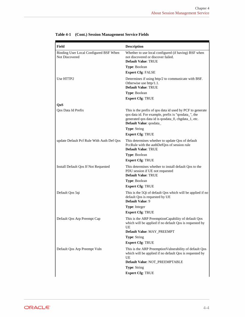
Binding User Local Configured BSF When Not Discovered
Whether to use local configured (if having) BSF when not discovered or discover failed. Default Value: TRUE Type: Boolean Expert Cfg: FALSE
Use HTTP2 Determines if using http/2 to communicate with BSF. Otherwise use http/1.1. Default Value: TRUE Type: Boolean Expert Cfg: TRUE
QoS Qos Data Id Prefix This is the prefix of qos data id used by PCF to generate
qos data id. For example, prefix is "qosdata_", the generated qos data id is qosdata_0, chgdata_1, etc. Default Value: qosdata_ Type: String Expert Cfg: TRUE
update Default Pcf Rule With Auth Def Qos This determines whether to update Qos of default PccRule with the authDefQos of session rule Default Value: TRUE Type: Boolean Expert Cfg: TRUE
Install Default Qos If Not Requested This determines whether to install default Qos to the PDU session if UE not requested Default Value: TRUE Type: Boolean Expert Cfg: TRUE
Default Qos 5qi This is the 5Qi of default Qos which will be applied if no default Qos is requested by UE Default Value: 9 Type: Integer Expert Cfg: TRUE
Default Qos Arp Preempt Cap This is the ARP PreemptionCapability of default Qos which will be applied if no default Qos is requested by UE Default Value: MAY_PREEMPT Type: String Expert Cfg: TRUE
Default Qos Arp Preempt Vuln This is the ARP PreemptionVulnerability of default Qos which will be applied if no default Qos is requested by UE Default Value: NOT_PREEMPTABLE Type: String Expert Cfg: TRUE

Chapter 4 About Session Management Service
4-5
Table 4-1 (Cont.) Session Management Service Fields
Field Description
Default Qos Arp Priority Level This is the ARP Priority Level of default Qos which will be applied if no default Qos is requested by UE Default Value: 1 Type: Integer Expert Cfg: TRUE
Rule
Install Default Pcc Rule This determine whether and how to install default pcc rule for a PDU session • ALWAYS • IF_NO_PROVISIONED_RULE: Only if no other
provisioned rule is configured • IF_NO_RULE: Only if no other rule (predefined or
provisioned) is configured/installed • NEVER Default Value: IF_NO_RULE Type: String Expert Cfg: TRUE
Rule Id Prefix This is the prefix of rule id of the pcc rule or session rule auto generated by PCF. for example, prefix is "0_", the generated rule id is 0_0, 0_1, etc. Default Value: 0_ Type: String Expert Cfg: TRUE
Default Pcc Rule 5qi This is the 5Qi of default pcc rule. Default Value: 9 Type: Integer Expert Cfg: FALSE
Default Pcc Rule Precedence This is the precedence of default pcc rule. Default Value: 3000 Type: Integer Expert Cfg: FALSE
Default Pcc Rule Arp Preempt Cap This is the ARP PreemptionCapability of qos of default PCC rule. • NOT_PREEMPT • MAY_PREEMPT Default Value: NOT_PREEMPT Type: String Expert Cfg: FALSE
Default Pcc Rule Arp Preempt Vuln This is the ARP PreemptionVulnerability of qos of default pcc rule • NOT_PREEMPTABLE • PREEMPTABLE Default Value: PREEMPTABLE Type: String Expert Cfg: FALSE

Chapter 4 About Session Management Service
4-6
Table 4-1 (Cont.) Session Management Service Fields
Field Description
App Rule Precedence Min This value defines the minimum value for precedence of a PCC rule as authorized by the establishment of an application flow by the AF. If multiple rules are applied to the same packet flow or UE resource (i.e., overlapping rules) a rule with lower precedence value takes the priority over a rule with higher precedence value. The value of -1 is used to not set the precedence of a rule (NOT RECOMMENDED). Default Value: 400 Type: Integer Expert Cfg: TRUE
App Rule Precedence Max This value defines the maximum value for precedence of a PCC rule as authorized by the establishment of an application flow by the AF. If multiple rules are applied to the same packet flow or UE resource (i.e., overlapping rules) a rule with lower precedence value takes the priority over a rule with higher precedence value. The value of -1 is used to not set the precedence of a rule (NOT RECOMMENDED). Default Value: 899 Type: Integer Expert Cfg: TRUE
Default Pcc Rule Arp Priority Level This is the ARP Priority Level of qos of default pcc rule The range is 1 to 15. Values are ordered in decreasing order of priority, for example, with 1 as the highest priority and 15 as the lowest priority. Default Value: 15 Type: Integer Expert Cfg: FALSE
Switch Flow In To Out Enabled This determines whether to switch "in" to "out" in flow description. The src and desc will be switched as well. For example, if enabled, "permit in ip from 2800:a00:cc01:c056:1c00:de10:c481:f193/128 to 2800:a00:800:7::1:3b/128 36004" will be changed to "permit out ip from 2800:a00:800:7::1:3b/128 36004 to 2800:a00:cc01:c056:1c00:de10:c481:f193/128" Default Value: FALSE Type: Boolean Expert Cfg: TRUE
Charging Charging Data Id Prefix This is the prefix of chg data id used by PCF to generate
chg data id. For example, prefix is "chgdata_", the generated chg data id is chgdata_0, chgdata_1, etc. Default Value: chgdata_ Type: String Expert Cfg: TRUE

4-7
Chapter 4 About NRF Client Service
Table 4-1 (Cont.) Session Management Service Fields
About Access and Mobility Service Access and Mobility Policy Control Service in PCF is responsible for handling interaction with AMF to privide policy rules including:
AM Policy Association establishes, modifies, and terminates the session initiated by AMF and PCF.
Configuring Access and Mobility Service You can edit and refresh the access and mobility service.
Table 4-2 Access and Mobility Service Fields
Field Description
System Log level Indicates the log level of PCF AM Service.
Default Value: WARN Type: String
Log Level Use Policy Service If selected, uses the policy service.
Component tracing is used to evaluate system process latency in detail level. Default Value:TRUE Type: Boolean
Use User Service If selected uses the user service Default Value:TRUE Type: String
Is Subscribe Indicates whether service is subscribed. Default Value: TRUE Type: String
Policy Type
Access control and mobility management related policy
Destination
to AMF to AMF
Sub Policy Type
SAR (Service Area Restriction) RFSP (Rat Frequency Selection Priori
Field Description
Traffic Control Traffic Control Id Prefix This is the prefix of traffic control data id used by PCF
to generate tc data id. For example, prefix is "tcdata_", the generated tc data id is tcdata_0, tcdata_1, etc. Default Value: tcdata_ Type: String Expert Cfg: TRUE

4-8
Chapter 4 About Access and Mobility Service
Table 4-2 (Cont.) Access and Mobility Service Fields
Field Description
Enable Http2 Client Enables http2 client Default Value: TRUE Type: String
App Default Service Area Restriction Determines the service area restriction. Default Rfsp Indicates the default Rfsp value. Default Triggers Indicates the default triggers.

5-1
5 Configuring Policy Control Function
This section provides the information for configuring policy control function for various services.
Configuring NRF Client Service User can configure nrfclient service by configuring the resources in their repository.
Table 5-1 provides the list of resources for configuring the nrf client service.
Table 5-1 NRF Client Services Resources
Configuring Session Rule Service You can create and manage session rules from the Session Rule Management screen. The page provides information about the existing session rules. You can create or refresh the session rules from this page.
Resource Resource URI HTTP Method or Description Custom Operation
nf-instances (Store) {apiRoot}/nnrf- nfm/v1/nf-instances
nf-instance (Document) {apiRoot}/nnrf- nfm/v1/nf-instances/ {nfInstanceID}
GET GET
PUT
PATCH
DELETE
subscriptions (Collection)
subscription (Document)
{apiRoot}/nnrf- nfm/v1/ subscriptions {apiRoot}/nnrf- nfm/v1/ subscriptions/ {subscriptionID} {nfStatusNotificatio nUri}
POST
DELETE
Read a collection of NF Instances. Read the profile of a given NF Instance. Register in NRF a new NF Instance, or replace the profile of an existing NF Instance, by providing an NF profile. Modify the NF profile of an existing NF Instance. Deregister from NRF a given NF Instance. Creates a new subscription in NRF to newly registered NF Instances. Deletes an existing subscription from NRF.
Notification Callback POST Notify about newly created NF Instances, or about changes of the profile of a given NF Instance.

5-2
Chapter 5 Managing Service Area Restriction
1. From the navigation menu, under Configurations, click Session Rule. The Session Rule Management screen appears.
2. Click Create. The create session page appears.
3. In the ID field, enter the session ID details.
4. In the Name field, enter the name for the session.
5. (Optional) In the Description field, enter the information about the session rule.
6. In Authorized Session AMBR section, enter the following:
a. In the Up Link Bandwidth field, enter the bandwidth details.
b. In the Down Link Bandwidth field, enter the bandwidth details. The bandwidth can be entered in bps, Kbps, Mbps, Gbps, and Tbps.
7. Click Save to create the session rule or click Cancel. If you have clicked Save, a new session rule is created.
8. Click Edit to edit the details of session rule.
9. Click Delete to delete the session rule.
Managing Session Rule Profile You can create and manage session rule profiles from Session Rule Profile Management screen. The page provides information about the existing session rule profiles. You can create or refresh the session rule profiles from this page.
To create a session rule profile:
1. From the navigation menu, under Configurations, click Session Rule Profile. The Session Rule Profile Management screen appears.
2. Click Create. The create session page appears.
3. In the ID field, enter the session ID details.
4. In the Name field, enter the name for the session.
5. (Optional) In the Description field, enter the information about the session rule.
6. In Authorized Session AMBR section, enter the following:
a. In the Up Link Bandwidth field, enter the bandwidth details.
b. In the Down Link Bandwidth field, enter the bandwidth details. The bandwidth can be entered in bps, Kbps, Mbps, Gbps, and Tbps.
Note:
Only administrators can create a session rule profile.
Note:
Only administrators can create session rules.
5-3
Chapter 5 Managing Session Rule Profile
7. Click Save to create the session rule profile or click Cancel. If you have clicked Save, a new session rule profile is created.
8. Click Edit to edit the details of session rule.
9. Click Delete to delete the session rule.
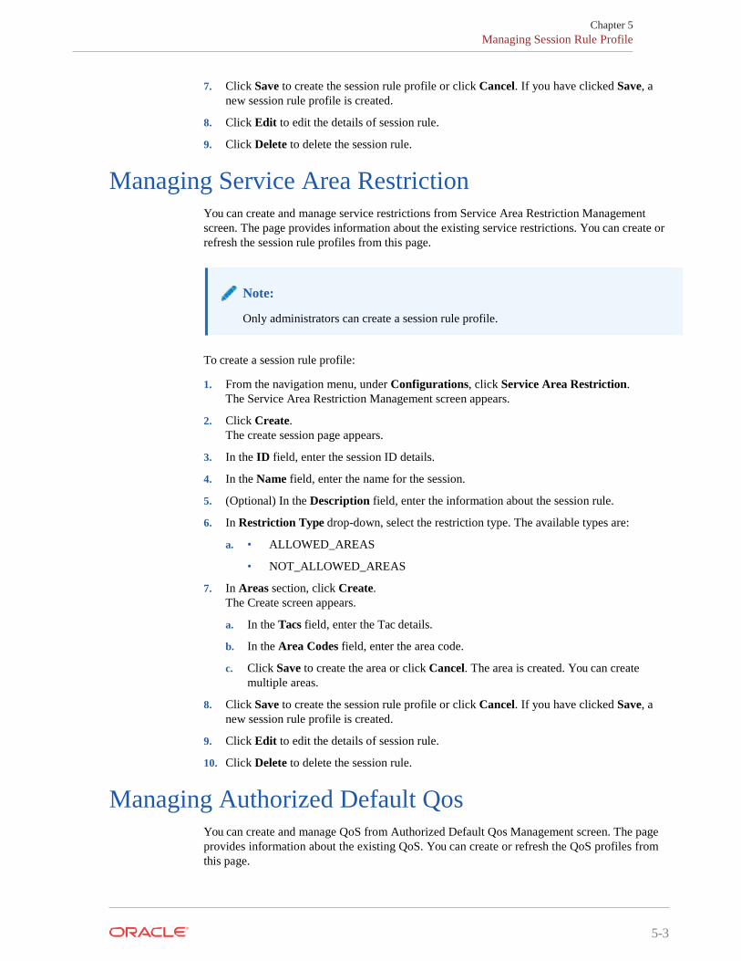
Managing Service Area Restriction You can create and manage service restrictions from Service Area Restriction Management screen. The page provides information about the existing service restrictions. You can create or refresh the session rule profiles from this page.
To create a session rule profile:
1. From the navigation menu, under Configurations, click Service Area Restriction. The Service Area Restriction Management screen appears.
2. Click Create. The create session page appears.
3. In the ID field, enter the session ID details.
4. In the Name field, enter the name for the session.
5. (Optional) In the Description field, enter the information about the session rule.
6. In Restriction Type drop-down, select the restriction type. The available types are:
a. • ALLOWED_AREAS
• NOT_ALLOWED_AREAS
7. In Areas section, click Create. The Create screen appears.
a. In the Tacs field, enter the Tac details.
b. In the Area Codes field, enter the area code.
c. Click Save to create the area or click Cancel. The area is created. You can create multiple areas.
8. Click Save to create the session rule profile or click Cancel. If you have clicked Save, a new session rule profile is created.
9. Click Edit to edit the details of session rule.
10. Click Delete to delete the session rule.
Managing Authorized Default Qos You can create and manage QoS from Authorized Default Qos Management screen. The page provides information about the existing QoS. You can create or refresh the QoS profiles from this page.
Note:
Only administrators can create a session rule profile.
5-4
Chapter 5 Managing PCC Rule
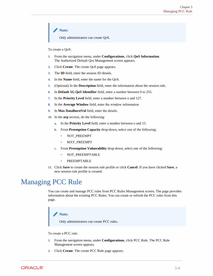
To create a QoS:
1. From the navigation menu, under Configurations, click QoS Information.The Authorized Default Qos Management screen appears.
2. Click Create. The create QoS page appears.
3. The ID field, enter the session ID details.
4. In the Name field, enter the name for the QoS.
5. (Optional) In the Description field, enter the information about the session rule.
6. In Default 5G QoS Identifier field, enter a number between 0 to 255.
7. In the Priority Level field, enter a number between o and 127.
8. In the Average Window field, enter the window information
9. In Max DataBurstVol field, enter the details.
10. In the arp section, do the following:
a. In the Priority Level field, enter a number between o and 15.
b. From Preemption Capacity drop-down, select one of the following:
• NOT_PREEMPT
• MAY_PREEMPT
c. From Preemption Vulnerability drop-down, select one of the following:
• NOT_PREEMPTABLE
• PREEMPTABLE
11. Click Save to create the session rule profile or click Cancel. If you have clicked Save, anew session rule profile is created.
Managing PCC Rule You can create and manage PCC rules from PCC Rules Management screen. The page provides information about the existing PCC Rules. You can create or refresh the PCC rules from this page.
To create a PCC rule:
1. From the navigation menu, under Configurations, click PCC Rule. The PCC RuleManagement screen appears.
2. Click Create. The create PCC Rule page appears.
Note:
Only administrators can create PCC rules.
Note:
Only administrators can create QoS.
5-5
Chapter 5 Managing PCC Rule
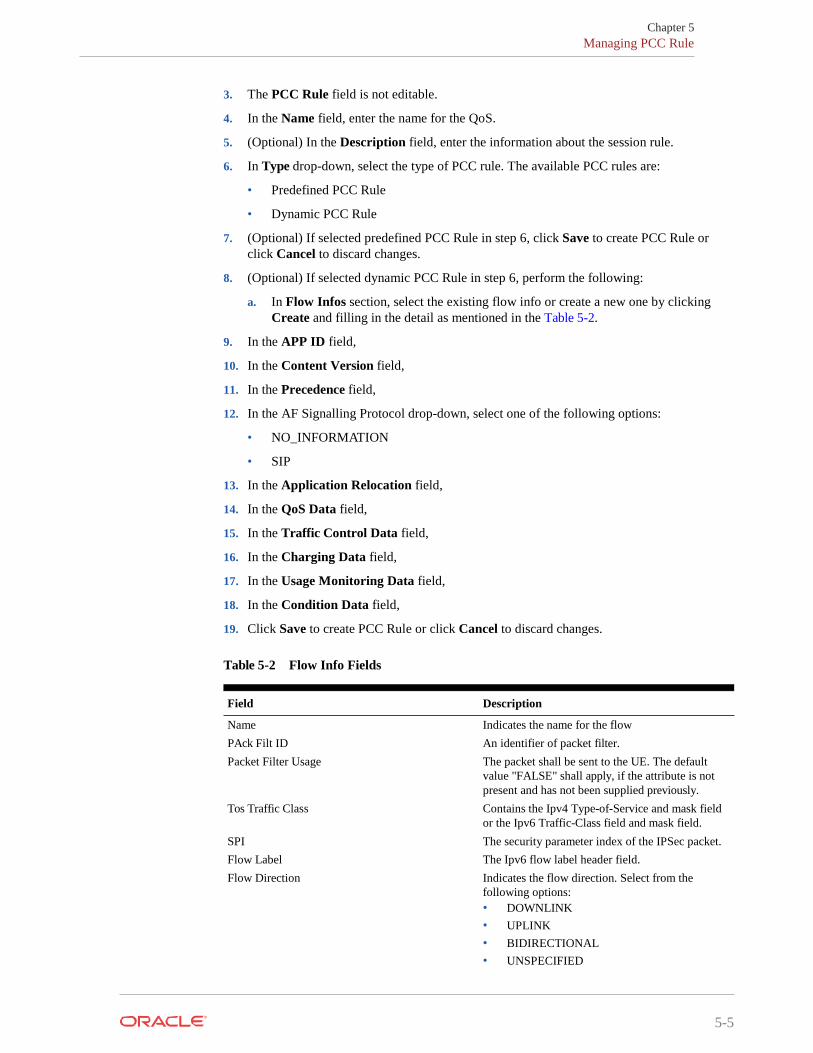
3. The PCC Rule field is not editable.
4. In the Name field, enter the name for the QoS.
5. (Optional) In the Description field, enter the information about the session rule.
6. In Type drop-down, select the type of PCC rule. The available PCC rules are:
• Predefined PCC Rule
• Dynamic PCC Rule
7. (Optional) If selected predefined PCC Rule in step 6, click Save to create PCC Rule or click Cancel to discard changes.
8. (Optional) If selected dynamic PCC Rule in step 6, perform the following:
a. In Flow Infos section, select the existing flow info or create a new one by clicking Create and filling in the detail as mentioned in the Table 5-2.
9. In the APP ID field,
10. In the Content Version field,
11. In the Precedence field,
12. In the AF Signalling Protocol drop-down, select one of the following options:
• NO_INFORMATION
• SIP
13. In the Application Relocation field,
14. In the QoS Data field,
15. In the Traffic Control Data field,
16. In the Charging Data field,
17. In the Usage Monitoring Data field,
18. In the Condition Data field,
19. Click Save to create PCC Rule or click Cancel to discard changes.
Table 5-2 Flow Info Fields
Field Description
Name Indicates the name for the flow PAck Filt ID An identifier of packet filter. Packet Filter Usage The packet shall be sent to the UE. The default
value "FALSE" shall apply, if the attribute is not present and has not been supplied previously.
Tos Traffic Class Contains the Ipv4 Type-of-Service and mask field or the Ipv6 Traffic-Class field and mask field.
SPI The security parameter index of the IPSec packet. Flow Label The Ipv6 flow label header field. Flow Direction Indicates the flow direction. Select from the
following options: • DOWNLINK • UPLINK • BIDIRECTIONAL • UNSPECIFIED
5-6
Chapter 5 Managing QoS Data
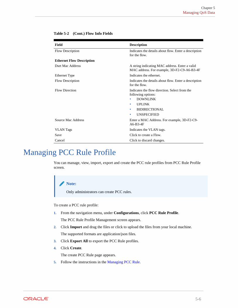
Table 5-2 (Cont.) Flow Info Fields
Field Description
Flow Description Indicates the details about flow. Enter a description for the flow.
Ethernet Flow Description Dset Mac Address A string indicating MAC address. Enter a valid
MAC address. For example, 3D-F2-C9-A6-B3-4F Ethernet Type Indicates the ethernet. Flow Description Indicates the details about flow. Enter a description
for the flow. Flow Direction Indicates the flow direction. Select from the
following options: • DOWNLINK • UPLINK • BIDIRECTIONAL • UNSPECIFIED
Source Mac Address Enter a MAC Address. For example, 3D-F2-C9- A6-B3-4F
VLAN Tags Indicates the VLAN tags. Save Click to create a Flow. Cancel Click to discard changes.
Managing PCC Rule Profile You can manage, view, import, export and create the PCC rule profiles from PCC Rule Profile screen.
To create a PCC rule profile:
1. From the navigation menu, under Configurations, click PCC Rule Profile.
The PCC Rule Profile Management screen appears.
2. Click Import and drag the files or click to upload the files from your local machine.
The supported formats are application/json files.
3. Click Export All to export the PCC Rule profiles.
4. Click Create.
The create PCC Rule page appears.
5. Follow the instructions in the Managing PCC Rule.
Note:
Only administrators can create PCC rules.

5-7
Chapter 5 Managing PCC Rule Profile
Managing QoS Data You can manage, view, import, export and create the QoS Data from QoS Data Management screen.
To create a QoS Data:
1. From the navigation menu, under Configurations, click QoS Data. The QoS Data Management screen appears.
2. Click Import and drag the files or click to upload the files from your local machine. The supported formats are application/json files.
3. Click Export All to export the QoS Data.
4. Click Create and fill the details as mentioned in the below table o create QoS Data.
Field Description
QoS Id Univocally identifies the QoS control policy data within a PDU session.
Name The name of the Qos Data Description The description of the Qos Data Default 5G QoS Identifier Identifier for the authorized QoS parameters for
the service data flow. It shall be included when the QoS data decision is initially provisioned and "defQosFlowIndication" is not included or is included and set to false.
Maximum Bit Rate UL Indicates the max bandwidth in uplink. Maximum Bit Rate DL Indicates the max bandwidth in downlink. Guaranteed Bit Rate UL Indicates the guaranteed bandwidth in uplink. Guaranteed Bit Rate DL Indicates the guaranteed bandwidth in downlink. ARP Priority Level Defines the relative importance of a resource
request. Preemption Capacity Defines whether a service data flow may get
resources that were already assigned to another service data flow with a lower priority level.
Preemption Vulnerability Defines whether a service data flow may lose the resources assigned to it in order to admit a service data flow with higher priority level.
QoS Notification Control Indicates whether notifications are requested from 3GPP NG-RAN when the GFBR can no longer (or again) be guaranteed for a QoS Flow during the lifetime of the QoS Flow. Default value is "FALSE", if not present and has not been supplied previously.
Note:
Only administrators can create QoS data.

5-8
Chapter 5 Managing Charging Data
Field Description
Reflective QoS Indicates whether the QoS information is reflective for the corresponding service data flow. Default value is "FALSE", if not present and has not been supplied previously.
Sharing Key UI Indicates, by containing the same value, what PCC rules may share resource in uplink direction.
Sharing Key DI Indicates, by containing the same value, what PCC rules may share resource in downlink direction.
Priority Level Defines the relative importance of a resource request.
Averaging Window Represents the duration over which the guaranteed and maximum bitrate shall be calculated (NOTE).
Maximum Data Burst Volume Denotes the largest amount of data that is required to be transferred within a period of 5G- AN PDB (NOTE).
Maximum Packet Loss Rate DI Indicates the downlink maximum rate for lost packets that can be tolerated for the service data flow.
Maximum Packet Loss Rate DI Indicates the downlink maximum rate for lost packets that can be tolerated for the service data flow.
Maximum Packet Loss Rate UI Indicates the uplink maximum rate for lost packets that can be tolerated for the service data flow.
Default QoS Flow Indication Indicates that the dynamic PCC rule shall always have its binding with the QoS Flow associated with the default QoS rule. Default value is "FALSE", if not present and has not been supplied previously.
Save Click to create qos data record. Cancel Click to cancel the changes.
Managing Charging Data You can manage, view, import, export and create the Charging Data from Charging Data Management screen.
To access a Charging Data:
1. From the navigation menu, under Configurations, click Charging Data. The Charging Data Management screen appears.
2. Click Import and drag the files or click to upload the files from your local machine. The supported formats are application/json files.
Note:
Only administrators can create Charging data
5-9
Chapter 5 Managing Charging Data
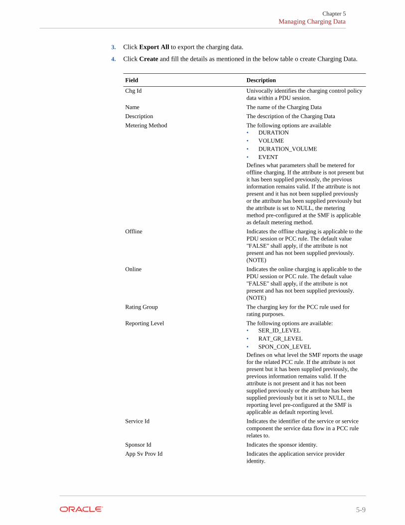
3. Click Export All to export the charging data.
4. Click Create and fill the details as mentioned in the below table o create Charging Data.
Field Description
Chg Id Univocally identifies the charging control policy data within a PDU session.
Name The name of the Charging Data Description The description of the Charging Data Metering Method The following options are available
• DURATION • VOLUME • DURATION_VOLUME • EVENT Defines what parameters shall be metered for offline charging. If the attribute is not present but it has been supplied previously, the previous information remains valid. If the attribute is not present and it has not been supplied previously or the attribute has been supplied previously but the attribute is set to NULL, the metering method pre-configured at the SMF is applicable as default metering method.
Offline Indicates the offline charging is applicable to the PDU session or PCC rule. The default value "FALSE" shall apply, if the attribute is not present and has not been supplied previously. (NOTE)
Online Indicates the online charging is applicable to the PDU session or PCC rule. The default value "FALSE" shall apply, if the attribute is not present and has not been supplied previously. (NOTE)
Rating Group The charging key for the PCC rule used for rating purposes.
Reporting Level The following options are available: • SER_ID_LEVEL • RAT_GR_LEVEL • SPON_CON_LEVEL Defines on what level the SMF reports the usage for the related PCC rule. If the attribute is not present but it has been supplied previously, the previous information remains valid. If the attribute is not present and it has not been supplied previously or the attribute has been supplied previously but it is set to NULL, the reporting level pre-configured at the SMF is applicable as default reporting level.
Service Id Indicates the identifier of the service or service component the service data flow in a PCC rule relates to.
Sponsor Id Indicates the sponsor identity. App Sv Prov Id Indicates the application service provider
identity.
5-10
Chapter 5 Managing Traffic Control Data
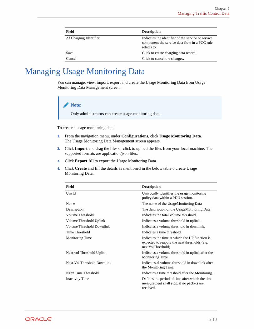
Field Description
Af Charging Identifier Indicates the identifier of the service or service component the service data flow in a PCC rule relates to.
Save Click to create charging data record. Cancel Click to cancel the changes.
Managing Usage Monitoring Data You can manage, view, import, export and create the Usage Monitoring Data from Usage Monitoring Data Management screen.
To create a usage monitoring data:
1. From the navigation menu, under Configurations, click Usage Monitoring Data. The Usage Monitoring Data Management screen appears.
2. Click Import and drag the files or click to upload the files from your local machine. The supported formats are application/json files.
3. Click Export All to export the Usage Monitoring Data.
4. Click Create and fill the details as mentioned in the below table o create Usage Monitoring Data.
Field Description
Um Id Univocally identifies the usage monitoring policy data within a PDU session.
Name The name of the UsageMonitoring Data Description The description of the UsageMonitoring Data Volume Threshold Indicates the total volume threshold. Volume Threshold Uplink Indicates a volume threshold in uplink. Volume Threshold Downlink Indicates a volume threshold in downlink. Time Threshold Indicates a time threshold. Monitoring Time Indicates the time at which the UP function is
expected to reapply the next thresholds (e.g. nextVolThreshold)
Next vol Threshold Uplink Indicates a volume threshold in uplink after the Monitoring Time.
Next Vol Threshold Downlink Indicates al volume threshold in downlink after the Monitoring Time.
NExt Time Threshold Indicates a time threshold after the Monitoring. Inactivity Time Defines the period of time after which the time
measurement shall stop, if no packets are received.
Note:
Only administrators can create usage monitoring data.
Chapter 5 Managing Usage Monitoring Data
5-11
Field Description
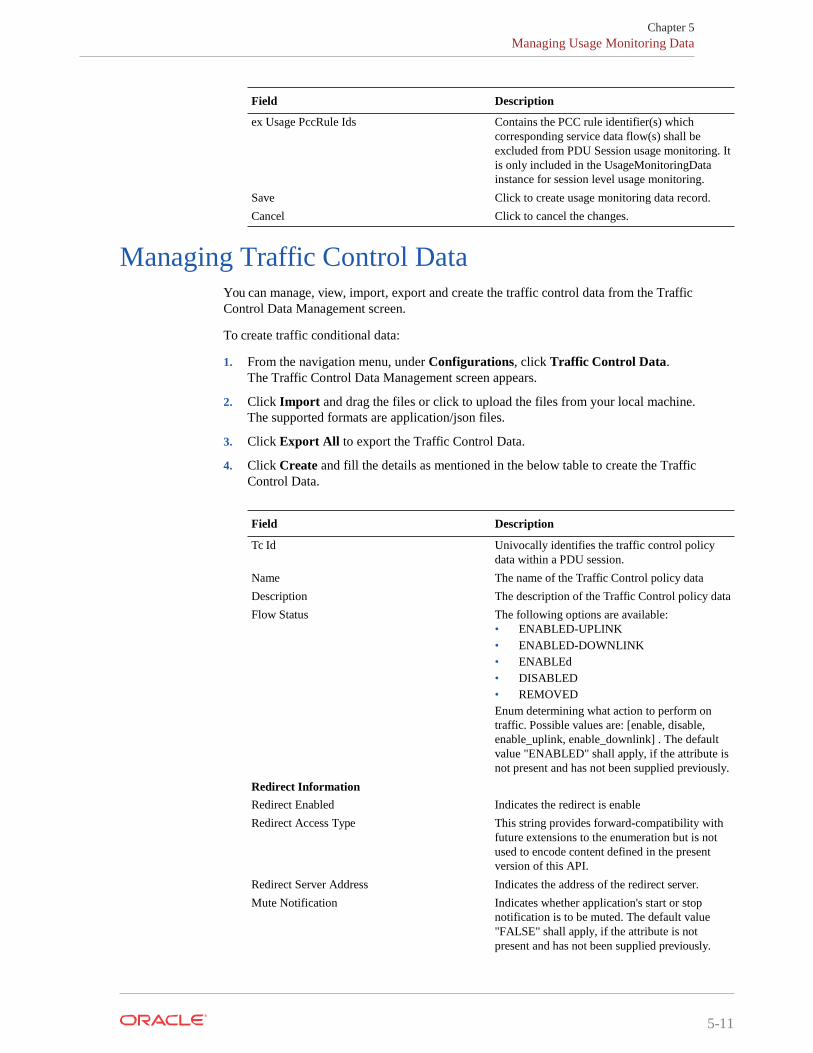
ex Usage PccRule Ids Contains the PCC rule identifier(s) which corresponding service data flow(s) shall be excluded from PDU Session usage monitoring. It is only included in the UsageMonitoringData instance for session level usage monitoring.
Save Click to create usage monitoring data record. Cancel Click to cancel the changes.
Managing Traffic Control Data You can manage, view, import, export and create the traffic control data from the Traffic Control Data Management screen.
To create traffic conditional data:
1. From the navigation menu, under Configurations, click Traffic Control Data. The Traffic Control Data Management screen appears.
2. Click Import and drag the files or click to upload the files from your local machine. The supported formats are application/json files.
3. Click Export All to export the Traffic Control Data.
4. Click Create and fill the details as mentioned in the below table to create the Traffic Control Data.
Field Description
Tc Id Univocally identifies the traffic control policy data within a PDU session.
Name The name of the Traffic Control policy data Description The description of the Traffic Control policy data Flow Status The following options are available:
• ENABLED-UPLINK • ENABLED-DOWNLINK • ENABLEd • DISABLED • REMOVED Enum determining what action to perform on traffic. Possible values are: [enable, disable, enable_uplink, enable_downlink] . The default value "ENABLED" shall apply, if the attribute is not present and has not been supplied previously.
Redirect Information Redirect Enabled Indicates the redirect is enable Redirect Access Type This string provides forward-compatibility with
future extensions to the enumeration but is not used to encode content defined in the present version of this API.
Redirect Server Address Indicates the address of the redirect server. Mute Notification Indicates whether application's start or stop
notification is to be muted. The default value "FALSE" shall apply, if the attribute is not present and has not been supplied previously.

5-12
Chapter 5 Viewing Sessions
Field Description
Traffic Steering Pol Id DL Reference to a pre-configured traffic steering policy for downlink traffic at the SMF.
Traffic Steering Pol Id UI Reference to a pre-configured traffic steering policy for uplink traffic at the SMF.
Route To Locs Dnai Identifies the location of the application. Route Information Includes the traffic routing information. IPV4 Addr Ipv4 address of the tunnel end point in the data
network. Ipv6 Addr Ipv6 address of the tunnel end point in the data
network. Port number UDP port number of the tunnel end point in the
data network. Route Profile Id Identifies the routing profile Id. Up Path Chg Event Notification Uri Notification Correlation Id It is used to set the value of Notification
Correlation ID in the notification sent by the SMF.
Dnai Change Type The following options are available: • EARLY • EARLY_LATE • LATE Possible values are - EARLY: Early notification of UP path reconfiguration. - EARLY_LATE: Early and late notification of UP path reconfiguration. This value shall only be present in the subscription to the DNAI change event. - LATE: Late notification of UP path reconfiguration. This string provides forward- compatibility with future extensions to the enumeration but is not used to encode content defined in the present version of this API.
Save Click to create traffic control data record. Cancel Click to cancel the changes.
Managing Condition Data You can manage, view, import, export and create the Condition Data from Condition Data Management screen.
To create a condition Data:
1. From the navigation menu, under Configurations, click Condition Data. The Condition Data Management screen appears.
2. Click Import and drag the files or click to upload the files from your local machine.
Note:
Only administrators can create condition data

5-13
Chapter 5 Managing Condition Data
The supported formats are application/json files.
3. Click Export All to export the Condition Data.
4. Click Create and fill the details as mentioned in the below table o create Condition Data.
Field Description
Cond Id Uniquely identifies the condition data within a PDU session.
Name The name of the Condition Data policy data Description The description of the Condition Data policy
data Activation Time The time when the decision data shall be
activated. Deactivation Time The time when the decision data shall be
deactivated. Save Click to create condition data record. Cancel Click to cancel the changes.
Viewing Sessions To view the sessions:
1. From the navigation menu, click Session Viewer. The Session Viewer page appears.
2. From the Session Type drop-down menu, select the session type whose sessions you want to view. The available options are:
• SM Policy Association
• AM Policy Association
3. In the Policy Association ID field, enter the session ID number.
4. Click Query.
Configuring Match List User can create and manage match list from Match List Management screen. The page provides information about the existing match lists. You can import, export, create or refresh the match list from this page. To create a match list:
1. From the navigation menu, under Common Configurations, click Match List. The Match List Management screen appears.
2. Click Create. The create match list page appears.
3. In the ID field, enter the match ID details.
4. In the Name field, enter the name for match list.
5. (Optional) In the Description field, enter the information about the match list.
6. In the Item drop-down, select one of the following:

5-14
Chapter 5 Viewing Sessions
• String
• Wildcard String
7. Click Save to create the match list or click Cancel. If you have clicked Save, a new match list is created.
8. Click Edit to edit the details of match list.
9. Click Delete to delete the match list.

Chapter 5 Configuring Match List
7-
6 Managing Policy
You can create and manage Policy projects.
Managing Policy Projects User can create, edit and delete project from this page.
Creating Policy Project
To create a policy project:
• Click Create.
• In the Name field, enter the name for the project.
• In the Description field, enter the description for the project.
• In the Service Type, select the service.
• Click Save to create the project.
Deleting Policy Project
To delete a policy project, select the project, and click Delete. Confirm the deletion.

6-1
7 Administering Policy Control Function
This section provides information for performing system administration.
As an administrator user can perform the following:
• Managing Users
• Managing Roles
• Managing Data Model
• Managing Dynamic Configuration Menu Demo
Managing Users The Manage Users page gives information about the users, their roles and their permissions. You can import, export, and create users, edit, and delete users from this page.
To create a user:
1. From the Home page, navigate to System Administration, and click User Management. The User Manage page appears.
2. Click Create. The Create User page appears.
3. In the User Name field, enter the username.
4. In the Password field, enter the password.
5. In the Confirm Password field, enter the password provided in te step 4.
6. Click Save to create user or click Cancel to discard the changes.
You can import bulk users by clicking Import and uploading the appropriate file with user information.
Managing Roles User can view and create new roles from this page.
To create roles:
1. From the Home page, navigate to System Administration, and click Role Manage. The Role Manage page appears.
2. Click New Role. The Create New Role page appears.
3. In the Role Name field, enter the name for the role
4. In the Privileges field, select the privileges for the role.

7-
Chapter 7 Managing Data Model
5. Click Save to create the role or click Cancel.
A new role will be created.
Managing Data Model The Data model page provides the details of existing data model services. You can create new services.
To create a data model service:
1. From the Home page, navigate to System Administration, click Data Model and thenclick Create.The create data model service appears.
2. In the Name field, enter the name for the service.
3. In the Label Name field, enter the label name.
4. In the Description field, enter the description of the service.
5. From the Type drop-down, select the type of service. The available options are:
• enum
• Object
6. Do one of the following:
• If you have selected Enum in step 6, in the Enum section, perform the following:
a. Click Create.
b. In the Name field, enter the name of the Enum
c. In the Value field, enter a value.
d. Click Save to create Enum or click Cancel to discard the changes.
• If you have selected Object in step 6, in the Fields section, perform the following:
a. Click Create.
b. In the Name field, enter the name of the Field.
c. In the Description field, enter the description of the service.
d. In the Label Name field, enter the label name.
e. From the Type drop-down, select the type of service. The available options are:
– Primitive
– Object
– Array
f. Based on the above selection, the description field appears. Fill the detailsaccordingly.
– Primitive Type: Select the primitive type from the drop-down list. Availableoptions are:
* String
* Number
* Boolean
7-2

7-3
Chapter 7 Managing Dynamic Configuration Menu Demo
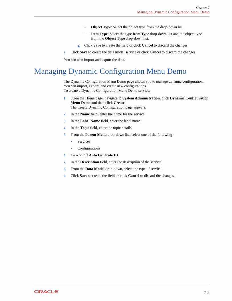
– Object Type: Select the object type from the drop-down list.
– Item Type: Select the type from Type drop-down list and the object typefrom the Object Type drop-down list.
g. Click Save to create the field or click Cancel to discard the changes.
7. Click Save to create the data model service or click Cancel to discard the changes.
You can also import and export the data.
Managing Dynamic Configuration Menu Demo The Dynamic Configuration Menu Demo page allows you to manage dynamic configuration. You can import, export, and create new configurations. To create a Dynamic Configuration Menu Demo service:
1. From the Home page, navigate to System Administration, click Dynamic ConfigurationMenu Demo and then click Create.The Create Dynamic Configuration page appears.
2. In the Name field, enter the name for the service.
3. In the Label Name field, enter the label name.
4. In the Topic field, enter the topic details.
5. From the Parent Menu drop-down list, select one of the following
• Services
• Configurations
6. Turn on/off Auto Generate ID.
7. In the Description field, enter the description of the service.
8. From the Data Model drop-down, select the type of service.
9. Click Save to create the field or click Cancel to discard the changes.