POLICIES AND PROCEDURES FOR PROCESSING WATER...
85
P POLICIES AND P PROCEDURES FOR P PROCESSING W WATER AND W WASTEWATER P PROJECTS F FOR D DESIGN AND C CONSTRUCTION A APRIL 1 1 9 9 9 9 9 9 i
Transcript of POLICIES AND PROCEDURES FOR PROCESSING WATER...

PPOOLLIICCIIEESS AANNDD PPRROOCCEEDDUURREESS
FFOORR PPRROOCCEESSSSIINNGG WWAATTEERR AANNDD WWAASSTTEEWWAATTEERR PPRROOJJEECCTTSS
FFOORR DDEESSIIGGNN AANNDD CCOONNSSTTRRUUCCTTIIOONN AAPPRRIILL 11999999
i
TABLE OF CONTENTS
Introduction Section I Standard Procedure Summary General Project Process Section II General Design Requirements for Water and Wastewater Pr ojects Section III Design Criteria for Water Projects General Pressure Plane Areas Design Criteria Section IV Design Criteria for Wastewater Projects (Revised 9/01/01) General Preliminary Design Procedure
Wastewater Mains and Laterals, Wastewater Lift Stations and Force Mains
Section V Easement Requirements Appendix Appendix A General Requirements for Developer’s Project (Revised 2/08/01) Appendix B Minimum Requirements for Developer’s Project (Revised 2/08/01) Appendix C Expediting Review and Approval of Plans Appendix D Pre-Qualification Requirements for Contractors (Revised 7/01/01) Appendix E Formal Community Facilities Agreement Appendix F Informal Community Facilities Agreement (Revised 9/08/00) Appendix G Standard Symbols and Abbreviations Appendix H Backflow Protection Appendix I Definitions Exhibits Exhibit 1 Flow Chart - Developer Project Approval
ii
Introduction
The purpose of this manual is to provide a set of minimum guidelines for the design and layout of water distribution and wastewater collection systems. These policies and procedures are applicable to engineering planning and design work performed by the Fort Worth Water Department, Engineering Department and engineering firms engaged by the City or by private interests. Deviations from these policies and procedures will not be acceptable except following discussion and approval by the Water Director. The policies and procedures established in this manual have been developed from a review of basic design engineering as contained in various publications and from recommendations from various individuals and professional organizations that oversee the engineering, construction and maintenance of the water distribution and wastewater collection systems. In addition, rules and regulations as published by the Texas Natural Resources Conservation Commission covering wastewater collection system and the Texas Water Commission covering water distribution system will also apply. This manual is to assist engineers in preparing designs for the construction of water and wastewater facilities. As such, it does not reflect construction procedures and techniques listed in the City of Fort Worth General Contract Documents and Specifications for Water Department Projects.
iii

SECTION I
STANDARD PROCEDURE SUMMARY
GENERAL The present policies and procedures for the planning and design of water and wastewater facilities are furnished in an effort to avoid delays, improve uniformity and secure adequate plans so that water and wastewater facilities will be planned and constructed as economically as feasible to meet present and future requirements. These policies and procedures are applicable to engineering planning and design work performed by the Water Department, Engineering Department, and by engineering firms engaged by the City or by private interests. These policies and procedures are guides to be followed and deviations normally will not be acceptable except following discussion and approval by the Water Department. Changes in these policies and procedures will be made and distributed from time to time to meet changing materials, methods, and needs. A conference between the City’s (Water and/or Engineering Department) Engineering Staff and the Consulting Engineer to discuss any special problems related to the project is desirable before the engineer begins preliminary design. A flow chart for Developer Project Approval is presented in Exhibit 1. PROJECT PROCESS 1. Water and Wastewater Study Report :
This Report is a comprehensive study of the development and the surrounding properties in order to evaluate the adequacy of the planned water and wastewater facilities for present and future needs. Water Comprehensive Study: A complete hydraulic analysis on water distribution system will be necessary to determine the sizes of water mains required to furnish adequate water service for both immediate and ultimate developments. Wastewater Comprehensive Study: A study of the drainage area will be required for wastewater projects. The size of the drainage area will determine the amount of information needed in the study report for the project.
1

The engineer is expected to make a field survey to verify the location of existing manholes, flow lines, and gate valves, from which extensions are to be made. The study in the form of an Engineering Report shall include the following items as a minimum:
A. Purpose and Scope B. Design Criteria C. Method of Analysis D. Results and Conclusions E. Supporting data and Calculations.
Three copies of this report should be submitted to the Water Department and Engineering Department either before or along with the preliminary design. Appendix A and B presents the General and Minimum requirements for developer’s projects to get building permit or plat released for projects over $25,000.
2. Preliminary Layout Review
Two copies of the preliminary layouts plans including the water and/or wastewater system layout, will be submitted by the Engineer to the Water Engineering Services Division for review. This submittal will consist of a plat, the proposed water and/or wastewater system layout, and the profile of the wastewater mains (as obtained from the design criteria of Section III and IV), and a copy of all design calculations. The preliminary design plans will include the following:
A. The general configuration of the water and/or wastewater main layout and their conformance to the overall plan of the area.
B. Fire hydrant and valve coverage. C. Adequate sizing of water and/or wastewater mains for present and future
requirements of the immediate and adjacent area. D. The Engineering Department Project Manager or the Water Department
Development Engineer and the Engineer during the review of the preliminary plans may make a field inspection survey on site.
E. Identification of right-of-way, easements and right-of-entry requirements. F. Adequacy of isolation valves.
After the Water Department has completed the review of the preliminary layout, one copy will be returned to the Engineer with review comments, and the project plans and specifications can be prepared.
The comprehensive study and the preliminary layout can be submitted together. 3. Preliminary Design Plans and Review
2

At this time, two (2) sets of design plans and two (2) copies of the Special Contract Documents and Specifications will be submitted by the Engineer to the Engineering Department or Water Department. All design plans and specifications for the project will be reviewed for completeness and compliance with the design criteria, policies and procedures of the Water Department. Changes, deletions, and additions, when necessary, will be noted on the plans and specifications. After review, one (1) set of design plans and one (1) copy of the Special Contract Documents and Specifications will be returned to the Engineer, with errors, corrections, additions or deletions indicated in red (or other designated color). The Engineering Department or Water Department will retain the other set as a record copy. The returned set should be used for preparation of final plans. Appendix C presents the Procedure for Expediting Review and Approval of Plans for Community Facilities.
4. Final Plans and Review
For the final review, two (2) sets of plans, two (2) sets of Special Contract Documents and Specifications, the original (reproducible) cover sheet, quantity take-off per sheet in a spreadsheet format and a copy of the project cost estimate shall be submitted by the Engineer. The “final” plans and specifications will be reviewed to determine if the plans and specifications are complete and all previous comments have been corrected or resolved. For signature of the cover sheet, the Engineer should have all appropriate seals and signatures affixed to the plans and specifications. One (1) set with the original cover sheet will be circulated within the City for approval and signature by the appropriate departments. The signed original cover sheet will be returned to the Engineer with any final comments. Pre-qualification requirements for contractors are presented in Appendix D.
5. Contract Award of Development Projects
Plans and Special Contract Documents and Specifications for all projects designed by Engineer shall be issued to prospective bidders through that consulting engineer’s office, and any information or clarification given to prospective bidders by the Engineer shall be furnished to all such prospective bidders in the form of an approved official addenda. The City (Engineering Department) will supply the Engineer with the General Conditions for Developer Projects, to be used in preparation of the Contract Documents. The Engineer is responsible for supplying the contractor with adequate number of plans and specifications.
3
Within ten (10) days after notification of contract award by the City, the Engineer shall submit the original drawings or reproducible drawings to the Engineering Department.
A. City Awarded Developer Projects.
The developer may elect for the City (Water Department) to award the Contract. After getting approval in writing from the Director of the Engineering Department, the project becomes the responsibility of the City upon approval of the final plans and specifications and after the developer has provided an executed formal (or informal) community facilities agreement. In addition, the developer must have submitted all appropriate fees, developer’s share of construction cost and sureties. The engineer will still provide the required number of final plans and specifications at the time the project is bid.
B. Developer Awarded Projects with City Cost Participation
(1) The engineer shall furnish the Engineering Department a memo setting forth the date and time bids are to be received and opened. The location must be at City Hall. If this time is found to be unacceptable to the Water Department or the Engineering Department, the engineer shall be notified and the time for the bid opening will be reset. NOTE 1
(2) On the date that the project is advertised for bids, the engineer shall
deliver to the Engineering Department Office at least two (2) sets of final plans and two (2) sets of final specifications. The engineer shall also transmit one set of plans to each of the utilities, with a copy of the letter of transmittal being forwarded to the DOE Office.
(3) At least 48 hours prior to receipt of bids, the engineer shall furnish to
the Engineering Department, a list of prospective bidders (this list may be added to with a telephone notification) to verify pre-qualification of bidders in accordance with the Water Department requirements. NOTE 1
(4) A City representative shall be present at the opening of the bids.
(5) After receipt and opening of bids, the engineer shall check the
proposals for accuracy and completeness and shall prepare bid tabulation, a copy of which shall be sent to each bidder of the project. The engineer shall submit the following to the Engineering Department office:
4

(a)
(b)
(c)
(d)
One copy of the newspaper’s affidavit of advertisement for bids certifying the said newspaper published such notice. The newspaper shall be the official newspaper of the City of Fort Worth (as designated by the City Council). Six (6) copies of the bid tabulation showing the bid proposals from all prospective bidders.(on City Format) Recommendation of award of contract by engineer, to the lowest responsive pre-qualified bidder. Breakdown of cost distribution of the project between the Developer and the City of Fort Worth per the Community Facilities Agreement (CFA).
(6) If the Water Department concurs with the recommendation for award
of the contract and after the Developer has provided an executed formal community facilities agreement (Appendix E), and provided all appropriate fees and sureties, the Engineering Department Office will issue such notification by letter (Confirmation of Award of Contract), which will become a work order (notice to proceed) after the stipulations in the letter are met.
(7) If developer desires to proceed with construction prior to execution of
the formal CFA, then an informal CFA must be executed.
NOTE 1: Caution: Failure to comply with Item a and c above shall result in no City representative being present at the bid opening, and consequently, the City will not participate in the cost of the project.
C. Developer Awarded Projects without City Cost Participation
The City will not participate in the bidding or negotiating process, except that the proposed contractor must be pre-qualified in accordance with Water Department requirements. After the contract is awarded, the engineer must submit a letter of recommendation for award of contract.
If the Water Department (Engineering Department) concurs with the recommendation for award of contract and after the Developer has provided an executed informal community facilities agreement (Appendix F), and provided all appropriate fees and sureties, the Engineering Department Office will issue such notification by letter (Confirmation of Award of Contract), which will become a work order (notice to proceed) after the stipulations in the letter are met.
5

D. Conformation of Award of Contract of Developer Awarded Projects
After the award of contract, the engineer shall submit, for the use of the City, the following number of final plans, specifications and additional layout sheets:
E
2 Water Layouts
Type of Project
Water & Wastewater
Water Only Project
Wastewater Only
Conformed Specs2. 5 5 5 Plans (full set)3 9 9 9 Water & Wastewater Layouts4
8
4 6 Wastewater Layouts4 5
NOTE 2: Shall consist of a signed contract (by contractor and
developer), performance and payment bonds (if contract amount exceeds $25,000) in the amount of the contract executed by a surety (acceptable to the City) in the name of the developer and the City covering the construction of the facilities, a maintenance bond in the amount of the contract executed by a surety (acceptable to the City) in the name of the developer and the City covering the constructed facilities against defects in materials/workmanship for one year after completion and acceptance, insurance certificates in amounts required by general conditions of the contract documents, executed easements as necessary, and completed bid document.
NOTE 3: Shall include signed cover sheet, layout sheets, plan and
profile sheets, detail sheets, and recorded plat of development. Entire set of plans and contract documents shall be signed and sealed by Registered Professional Engineer in the State of Texas.
NOTE 4: In addition to plan sets provided. Layout shall include lot line
locations, location of services (water and wastewater), manholes (wastewater), valves and vaults (water), fire hydrants (water), and other appropriate information.
6

SECTION II
GENERAL DESIGN REQUIREMENTS
FOR WATER AND WASTEWATER PROJECTS
A policy has been adopted that all ‘as-built” plans will be reduced to one-half scale by the Engineering Department. Therefore, it is essential that the CAD technicians or draftsperson preparing final plans be made aware that prints from reduced originals will be used for future reference so that they may perform their work with this requirement in mind. The Water Department requires that plans be prepared on sheets measuring 24” x 36”. To maintain uniformity of plans and to meet the minimum requirements of the Fort Worth Water Department, the project engineer will provide the following information of the plans: 1. Existing construction such as pavement, curbs, gutters, driveways, drainage
structures, utilities, railroad tracks, and buildings (in or adjacent to the proposed improvements), shall be clearly located in the plan and in the profile wherever it is necessary for the clarification of the design.
2. Approved design of any proposed construction, which may be pertinent to the
design of the project, shall be clearly located in the plan and in profile as necessary to clarify design.
3. Profiles of all proposed or existing streets containing water and wastewater
utilities shall be included in the plans or made available as needed through the Transportation and Public Works Department.
4. Construction and permanent easements shall be delineated on the plans, including
the affected property owner’s name and easement reference designation in the project specifications. Copies of executed easements shall be part of the Special Contract Document and Specifications for the project.
5. All utilities, including pipe lines, underground cables, power, telecommunication
wires, poles, meter boxes, vaults, manholes etc., shall be clearly located in all proposed and existing dedications to contain water and wastewater utilities, both in plan and profile.
6. Scales are to be shown on each sheet, both numerically and graphically.
Acceptable scales are:
7

STANDARD PLAN & PROFILE 1” = 4’ vertical 1” = 40’ horizontal 1” = 100’ layout Exceptions may be approved by the Fort Worth Water Department when a double scale would show the overall layout more clearly.
7. Street names, R.O.W and pavement widths, types of surfacing, curbs and proposed curbs shall be shown where pertinent to the proposed water and wastewater utilities.
8. Notes to reconstruct any driveways, sidewalks, ramps, parking lots, etc. affected
by design should be shown. 9. Notes to reconstruct streets, fences, etc., which are affected by design should be
shown. 10. Notes pertinent to connections with existing water and wastewater utilities should
be included. 11. A North arrow and Tarrant Appraisal District map number should be shown on
each plan view. 12. Topography notations should be included as necessary for clarification of design. 13. The location of all benchmarks (permanent or temporary) shall be shown on the
plans (minimum of two). The location of the nearest permanent benchmark shall be described and shown if the on-site benchmarks are temporary. Also, provide minimum of two survey control points for each line segment
14. Existing and future surface grades should be shown (on the profile) and labeled. 15. Label all wastewater sizes, grade lines and profiles. Show datum elevations as
often as necessary for clarification. Pipe sizes 10-inch and above, indicate in mgd the capacity required and provided.
16. Show water profiles for pipes 12-inch diameter and greater, valves, percent grade,
pipe material and other utilities, etc. 17. Onsite water and wastewater systems shall be displayed on different layout
sheets. Onsite wastewater profiles must be shown separate, indexed by line
8
numbers on the layout sheet may be used. The line weight needs to be lighter than Off-site work.
18. All wastewater mains, which are substantially cross-country (or off-site) will
required a combined plan and profile drawing(s). 19. Services for water and wastewater will be shown on the separate layout sheet, but
stationing of services will not be required (unless the service locations deviate from the standard locations), and wastewater service grades will not be required.
20. Any additional information not specifically mentioned above which will add to
the clarity of the plans and specifications should be included. 21. A copy of the recorded (or proposed) final plat of the project area shall be
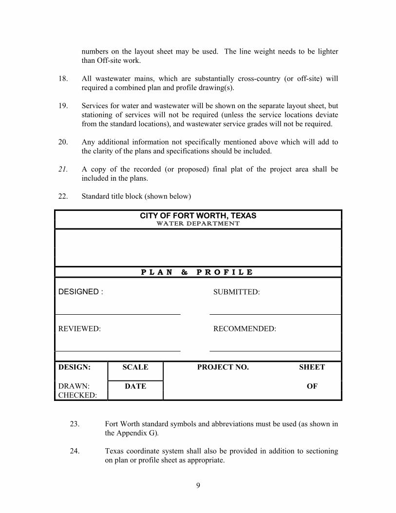
included in the plans. 22. Standard title block (shown below)
CITY OF FORT WORTH, TEXAS WATER DEPARTMENT
P L A N & P R O F I L E DESIGNED :
SUBMITTED:
REVIEWED:
RECOMMENDED:
DESIGN: SCALE PROJECT NO. SHEET DRAWN: DATE OF CHECKED:
23. Fort Worth standard symbols and abbreviations must be used (as shown in the Appendix G).
24. Texas coordinate system shall also be provided in addition to sectioning
on plan or profile sheet as appropriate.
9
25. On each sheet there shall be a “Warning to the Contractor” note requiring
the location of any utilities 48 hours prior to any execution.
26. On all water and wastewater plan sheets, show stationary objects (e.g. valves, hydrant, manholes, etc.)
27. Provide general construction notes as needed.
10

SECTION III
DESIGN CRITERIA FOR WATER PROJECTS GENERAL The following are the minimum Standard Design Criteria that must be met for all water improvements in order to meet the requirements of 30 TAC Chapter 290, Sections 290.38 through 290.47, the City of Fort Worth Ordinance #7234 (Subdivision Ordinance), and the City of Fort Worth Policy for the Installation of Community Facilities, also to be approved for incorporation into the Fort Worth Water System. 1. AVERAGE DAY WATER USE: 215 gallons per capita per day (GPCD) 2. MAXIMUM DAY: For “Maximum day” unrestricted use, multiply the annual
Average day by 2.25 3. MAXIMUM HOUR: For the “Maximum Hour” unrestricted use, multiply the maximum day by 2.00 4. POPULATION DENSITY: 18 persons per acre 5. PERSONS PER RESIDENTIAL CONNECTION: 3.5 people/connection 6. HEAD LOSS: Maximum rate of head loss due to friction in a water main should not exceed 5-7 feet/thousand feet. 7. FIRE FLOW: Fire flow should be rated at 1,000 gallons per minute (GPM) in
residential areas. Fire flow for commercial and industrial areas should be a minimum of 1,500 GPM or per current Fire Code requirements.
8. DESIGN SIZE: Water mains should be sized to meet Maximum Hour or
Maximum Day plus Fire Flow, whichever is greater. However, no pipe size shall be less than 8-inch.
9. COMPUTIONS: Maximum Day/Connection = (2.25)(215 GPCD)(3.5 p/c) = 0.00169 MGD
1,000,000 Maximum Hour/Connection = (2.00)(0.00169 MGD) = 0.00338 MGD
11
10. SUPPLY STORAGE VERSUS PUMPING: The maximum hour demand should be supplied with not less than 60% from pumping capacity and not more than 40% from available “elevated” storage.
11. ELEVATED STORAGE DEPLETION: Elevated water storage should be
maintained not less than 33% full during maximum hour demand period. 12. PIPE CLASS VERSUS PRESSURE: Refer to the Fort Worth Water Department
General Contract Documents and General Specifications. 13. QUICK CLOSING VALVES: Quick-closing valves will not be permitted in any
water facility connected to the Fort Worth Water System. 14. MINIMUM WORKING PRESSURE: In residential areas, the working pressure
in mains shall not be less than 35 p.s.i. as specified in the TNRCC’s regulations. PRESSURE PLANE AREAS The City is divided into pressure plane areas designated as follows: 1. HOLLY PLANE: The central area of the City, which is served from the Holly
Water Treatment Plants directly, without re-pumping, which lies below ground elevation 640’. The storage overflow is 760’.
2. SOUTH SIDE II PLANE: The area south and south west of the Holly Plane
between the ground elevations of 640’ and 720’. The storage overflow elevation is 850’.
3. SOUTH SIDE III PLANE: The area south and south west of the Southside II
Plane between the ground elevations of 720’ and 860’. The storage overflow elevation is 990’.
4. SOUTH SIDE IV PLANE (Projected): T h e p r o j e c t e d a r e a s o u t h o f t h e
Southside III plane above ground elevation of 860’. The storage overflow elevation is projected to be 1075’.
5. WEST SIDE II PLANE: The area west of the Holly Plane between ground
elevation 640’ and 730’. The storage overflow is 857’. 6. WEST SIDE III PLANE: The area west of the West Side II Plane between the
ground elevations of 730’ and 840’. The storage overflow elevation is 975’. 7. WEST SIDE IV PLANE: T h e p r o j e c t e d a r e a w e s t o f t h e We s t S i d e
III Plane above ground elevation of 840’. The storage overflow elevation is projected to be 1075’.
12
8. NORTH SIDE II PLANE: The area north, northwest, and northeast of the Holly Plane between ground elevations of 640’ and 730’. The storage overflow elevation is 853’.
9. NORTHSIDE III PLANE: The area north and northwest of the North Side II
Plane between the ground elevations of 730’ and 830’. The current storage overflow elevation is 936’, the future overflow elevation will be 950’.
10. EAST SIDE II PLANE: The area east of the Holly Plane area between
ground elevation 640’ and 680’. The storage overflow elevation is 805’. This plane also includes the area east of IH-35 and north of Holly Plane.
13

DESIGN CRITERIA 1. Minimum Water Line Size: The following design criteria shall be considered to
be the minimum basis for sizing water lines in various locations to be incorporated into the Fort Worth Water distribution system:
A. Residential Water Service: The minimum size residential water service
line for new residential development shall be 1-inch.
A 1-inch water service with two ¾-inch meters (commonly called a “bullhead” connection) can be installed for residential duplex lots or for contiguous single family residential lots having a front footage of 40 feet or less.
B. Residential & Commercial Water Lines: The minimum water main size
for a residential (defined as “single-family” detached or two-family/duplex housing) area or a commercial (defined as development not composed of “single-family” detached or two-family/duplex housing and industrial developments) area is eight (8) inches (I.D.), or such larger size as may be necessary to properly serve the proposed and existing development.
C. Industrial Water Lines: The minimum water main size for a industrial area
is twelve (12) inches (I.D.), or such larger size as may be necessary to properly serve the proposed and existing development.
2. Sizing Water Mains
A. Industrial Areas: For large industrial sites or areas, water mains will be sized to meet projected demand for both industrial requirements and fire coverage.
B. Multi-Family Demand: Peak demand for multi-family development shall
be determined on the basis of not less that that required under the following formula published in June 1967, AWWA Journal.
Q = U + 15 U Where: U is equal to the number of apartment units Q is equal to Water Demand in GPM (gallons per minute) C. Fire Flow Requirements: In addition to the normal maximum hour water
service requirements, full consideration shall be given to fire flow requirements as superimposed upon the maximum day demand conditions, elevation, and the type of development proposed, in arriving at the final water main capacity.
14
D. Fire Flow Demands: Fire flow should be rated at 1,000 gallons per minute (GPM) in residential areas. Fire flow for commercial and industrial areas should be a minimum of 1500 GPM or per current Fire Code requirements.
3. Water Main Location: The following design criteria shall be considered to be the
normal locations for water mains in the Fort Worth Water distribution system:
A. Residential Water Service: The normal location of the residential water service shall be in the parkway in front of the property and five (5) feet east or north of the center of the property frontage.
B. Normal Water Main Location: The normal location of water mains shall
be 5 feet off North or East property line (either existing or proposed).
C. Water Mains on Divided Thoroughfares or Wide Paved Street: To prevent cutting the pavement on divided thoroughfares and wide paved streets (greater than 60 LF) a double main system may be used. The capacity of the two parallel water mains shall not be less than the required capacity of a single line designed to serve the area.
D. “Services” Crossing Divided Thoroughfares or Wide Paved Streets: When
the proposed water service requires crossing over half of divided thoroughfare (either existing or proposed) or across more than 40 linear feet (perpendicular to street center line) of street pavement (either existing or proposed), the proposed service shall be made as a public water main extension in order to meet all the requirements of this section.
4. Valve Location & Requirements: The following design criteria shall be
considered to be the standard locations and requirements for valves in the Fort Worth Water distribution system.
A. Fire Hydrants: All fire hydrants leads shall have a gate valve (min 6-inch)
and anchor tee. B. Valves: Unless approved by the Water Department, only approved gate
valves will be used in the distribution system. C. Isolation Valves: Valves shall be located to allow isolation of specific
section of the distribution system to prevent shutting off more than once, services those customers who are served by water lines outside. Usually this will be a water main under a street between two cross streets. Water valves are usually located in street intersections or at water line crosses or tees. The location of valves should be approved by the Water Department.
15
D. Transmission Mains: All water line connections (water services, mains etc.) shall have a gate valve at connections to a water transmission line.
E. Vaults for 16-inch Valves & Larger: All valves that are 16-inches or
larger shall be in a valve vault. A Corporation and curb stop shall be provided on each side of the valve (no more than 12-inches from the valve). Corporation and curb stop shall be 1-inch for 16-inch through 24-inch water pipe and shall be 2-inch for 30-inch and larger water pipe.
F. By-Pass for 16-inch Gate Valves and Larger: All 16-inch Gate Valves or
larger, shall have a bypass valve, unless approved by the Water Department.
5. Fire Hydrant Location: The following design criteria shall be considered to be
the normal locations for fire hydrants in the Fort Worth Water distribution system. Only approved national standard three-way 6-inch fire hydrants with threads that match fire hydrants in use by the Fort Worth Fire Department will be allowed: Fire Hydrant locations should be reviewed by the Fire Prevention Bureau of the Fort Worth Fire Department :
A. Maximum Distance from Fire Hydrants:
(1) One and Two Family Residences: For all one and two family
residences, fire hydrants must be installed within (or along) a 500 foot radius along a direct horizontal line from residence, and must be within 800 feet “hose lay” using the most direct route of access between fire hydrant and building.
(2) Other Land Uses: For all other land uses, fire hydrants must be installed within (or along) a 300 foot radius along a direct horizontal line from building, and must be within 500 feet “hose lay” using the most direct route of access between fire hydrant and building.
B. Cul-de-Sacs: Streets longer than 300 feet, which end in a cul-de-sac, must
have a fire hydrant in the cul-de-sac. When the cul-de-sac is less than 300 feet from the center of the connecting street intersection, a fire hydrant is required at the connecting street intersection.
C. Street Location: All fire hydrants must be installed at least two and one
half (2-1/2) feet, but less than nine (9) feet, from the back of the curb of the paved street or edge of a designated approved fire lane. Normal location is three (3) feet behind the curb. Location for fire hydrant should be selected to provide shortest possible lead under street pavement.
16
D. Ground Elevation: The ground line on the fire hydrant in a standard installation shall be set even with the elevation of the top of the adjacent existing or proposed curb (elevation specified). When parkways are to be developed with a rolling or irregular slope, the ground line index on the fire hydrant shall be set to the proposed ground elevation (specified) at the point of installation.
E. Private Fire Hydrant: Where the fire hydrant is on a metered line, fire
hydrant must be maintained by Owner and not obstructed. Paint in red color to differentiate from public fire hydrant (aluminum).
F. Siamese Connection: Siamese connection must be within 50 feet of a fire
hydrant. 6. Fire Lines: The following design criteria shall be considered to be the normal
requirements for fire lines in the Fort Worth Water distribution system. All projects requiring fire lines shall be presented to the Bureau of Fire Prevention (Fort Worth Fire Department) for review:
A. Double Detector Check Valve: All fire lines are required to have a double
gate double detector check valve assembly. The double detector check valve and vault is to be located on private property (Appendix H - Backflow Protection).
B. Siamese Connection: When Siamese connection is required, it must be
located on the discharge (customer) side of the meter.
C. Fire Line Testing: The Bureau of Fire Prevention (Fort Worth Fire Department) is responsible for inspection and testing of all fire lines on owner side of meter, gate valve, or back flow preventor.
7. Pressure Regulators: In low areas where pressures may exceed 80 psi, builders and plumbers should be advised that in such locations pressure reducing devices should be installed in accordance with the current Plumbing Code adopted by the City of Fort Worth. Pressure reducing valves will not be installed in the public water system.
8. Air Release & Vacuum Relief Combination Valves: Combination air and vacuum relief valves shall be installed in high points along feeder mains, transmission mains or major mains to exhaust trapped air or relief vacuum from the water distribution system. The size and type are as follows:
Water Line Size Size of Relief Valve Type of Relief Valve 16-inch & Smaller 1-inch Combination 18-inch to 36-inch 2-inch Combination 42-inch and above 3-inch Combination
17

These combination relief valves shall be installed in vaults per the General Contract Documents and General Specifications
Blow-off Valves & Vaults: In low points along transmission lines (16-inch and larger), blow-off valves and vaults shall be required in the system to drain the mains. The sizes generally are :
9.
Size of Water Main Size of Blow-off 16-inch and Below 4-inch 18inch to 42-inch 6-inch 48-inch and above 8-inch 10. Clean Out Wyes: In strategic locations along lateral water lines, water feeder
mains, water transmission mains, etc., cleaning wyes shall be provided for passing “Cleaning Pigs” through the water line to sweep trash, dirt and debris from the pipe. These wyes shall be supplemented with chlorination and sampling points, as required for disinfecting of the water main. The Development Engineer will approve location of these wyes (chlorination and sampling points).
11. Water Sample Stations: Water sample stations are required to meet regulatory
requirements. These stations may be installed at the request of the City at major intersections, water transmission line tees/crosses, large water meters, or other locations to be designated by the Water Department.
12. Back Flow Prevention Devices: All service connections to the Fort Worth Water
Distribution System shall have a back flow prevention device (see Exhibit 1 and 2).
13. Meters Larger than 2-Inches In Size: Water meters that are larger that 2-inches in
size shall have the following:
A. Meter Vault: Meter shall be installed in a vault.
B. Bypass: All meters larger than 2-inches shall have a bypass in accordance with Exhibit in Appendix H.
C. Type of Meter: All meters larger than 2-inch shall be a combination meter (large and small meter).
D. Purchase: All meters shall be purchased from the Water Department.
18

SECTION IV DESIGN CRITERIA FOR WASTEWATER PROJECTS
GENERAL The following are the minimum standard Design Criteria that must be met for all wastewater main improvements in order to meet the requirements of 30 TAC Chapter 317, Sections 317.1 through 317.3, the City of Fort Worth Ordinance #7234 (Subdivision Ordinance), and the City of Fort Worth Policy for the Installation of Community Facilities, also to be approved for incorporation into the Fort Worth Wastewater Collection System. WASTEWATER MAINS AND LATERALS 1. BASIC PRELIMINARY INFORMATION
A. Determine the total area within the natural drainage limits to be served by the proposed mains/laterals using information below:
(1) Topographic or contour maps, (2) Field surveys, (3) Highway drainage information, (4) As builds, (5) Other suitable material
B. Estimate the current and/or future population load to be served by the
main/lateral. In no case it shall be less than the population obtained by multiplying the gross area under “A” above, by 18 people per acre. However, this minimum population shall not be employed in place of sound information relating to a particular area in question indicating a higher population than the minimum.
C. Prepare a preliminary map of the area to be served by the main, both
present and future, on which shall be shown: (1) Limits of the drainage area, (2) All subdivisions, recorded or not (3) All known proposed subdivisions, preliminary plats or concept plans, (4) Location of all water and drainage ways both natural and man-made, (5) Tentative location of proposed main, showing probable point of
19
connection to existing wastewater system. (A check should be made at this time to establish whether or not, “front foot” charges, or other similar charges are applicable for connection to the existing wastewater main),
(6) All existing state, county, and city highways, roads, streets, and right-of-way dedicated for public use and any proposed (see master thoroughfare plan) street,
(7) Property lines and utility easement lines of all tracts in the vicinity of the main location with present owners shown.
2. PRELIMINARY DESIGN PROCEDURE
A. Make a preliminary survey of the tentative main location, along with such alternate locations as this field survey might indicate as desirable. This survey includes: (1) Baseline surveys showing relation between property
corners and proposed wastewater main centerline. This information shall be in sufficient detail to properly locate the proposed main on the preliminary map and to determine the number of properties involved for securing the necessary right-of-way and easements.
(2) Profile survey showing:
(a) Field-determined elevation of any existing manhole
invert, stub, or wastewater main to which the proposed wastewater lines is to connect.
(b) Elevation of the ground at centerline of the proposed main at each stations, half station and/or ground break.
(c) Elevation of ground, 100 feet left and right of centerline at each station.
(d) Elevation at any draw, creek, depression, pond, lake or water course within any portion of the centerline at intervals not to exceed 10 feet, with proper reference made as to location with respect to centerline.
(e) As appropriate elevation of service stub out of each existing house or building to be served directly by the main. In case service stub is not available, finish floor or basement elevation should be shown at the front and back of the house. In any event, care should be taken to properly
20
locate the existing house and points of elevation taken with relation to centerline.
B. Prepare preliminary plan and profile drawing for the mains showing the information obtained from the preliminary survey.
(1) Station 0+00 of the proposed main shall be equated to the
interceptor main stations at the point of connection (usually a manhole). The exception would be the continuation of an existing main, in which stationing would continue from the point of connection to the existing main. In no case should the engineer renumber or rename any existing main or lateral number and stationing.
(2) The plot of the main on the profile sheet shall be from left to right,
beginning at Station 0+00 (lowest flow line elevation), and progressing right in increasing stations to the highest flow line elevation.
C. Analyze the data obtained previously and the result from the
wastewater collection system hydraulic modeling effort. Determine the points where each increment of load will be added to the proposed main and prepare a tabulation showing the estimated magnitude of the population load under ultimate conditions at each of those points, showing both the incremental and cumulative load. For pipe size 10-inch and above show on the profile of each segment of wastewater main the capacity required and the capacity provided in million gallons per day.
D. Adjust preliminary grade on the profile, keeping in mind that this grade
should be sufficiently deep to accept not only the normal direct connections, but in general, the top of the proposed main should be: (1) Not less than two feet below the bottom of such drainage course
being paralleled; (2) Far enough below the bottom of such drainage course to permit a
4-inch service line to pass under the drainage course with one foot of cover, approach the proposed main on at least a 1.00% grade, and match top of pipe with the proposed main at the point of connection; or
(3) Not less than five feet below the finished grade of the street in
which it is to be located.
E. Determine the limiting or latest gradient between each point of load increment
21
F. Recheck all steps in the PRELIMINARY DESIGN PROCEDURE to be
sure that the location and grade selected for the proposed main as the end result of this procedure are to be the best possible combinations obtainable under governing circumstances.
WASTEWATER LIFT STATIONS AND FORCE MAINS (Revised 9/01/01)
The Fort Worth Water Department will determine the proposed capacity and future expansion capacity. The lift station will also have remote monitoring capability as required by the Water Pollution Division of the Fort Worth Water Department.
Wastewater force mains will be sized to meet the ultimate capacity of the lift station. The force main material will be a pressure grade pipe acceptable to the Fort Worth Water Department. Section IV-1 Introduction
1.1 Purpose 1.2 Responsibility of the Engineer 1.3 Design and Material Variances 1.4 State Requirements
Section IV-2 Civil Design Criteria
2.1 Wastewater Flow Calculations 2.2 Site Considerations 2.3 Wetwells 2.4 Valve Vaults 2.5 Ventilation and Odor Control 2.6 Force Mains 2.7 Receiving Gravity Sewer
Section IV-3 Structural Design Criteria
3.1 Geotechnical Report 3.2 Buoyancy 3.3 Structural Design Considerations 3.4 Structural Details
Section IV-4 Mechanical Design Criteria
4.1 Pumps 4.2 Piping 4.3 Valves 4.4 Access Hatches 4.5 Ladders and Safety Equipment 4.6 Interior Hardware 4.7 Pipe Penetrations
22
4.8 Pressure Gauges Section IV-5 Electrical and Instrumentation Design Criteria
5.1 Pump Control and Level Monitor 5.2 Load Analysis 5.3 Single Line Diagrams 5.4 Control Wiring Diagrams 5.5 Enclosure Layout Schematics 5.6 Enclosures 5.7 Lighting Requirements 5.8 SCADA Monitoring
Section IV-6 Project Closeout
6.1 Execution 6.2 Operation and Maintenance Manuals 6.3 Pump Manufacturer Warranty 6.4 As-Builts 6.5 Project Closeout
23
24

SECTION IV-1 - INTRODUCTION
1.1 Purpose The purpose of this document is to provide guidance and design criteria by which design engineers may develop site specific plans and specifications for new wastewater lift stations which are to be turned over to the Fort Worth Water Department for ownership, operation, and maintenance. 1.2 Responsibility of Engineer The Fort Worth Water Department requires that proposed developments provide gravity wastewater service where possible. In the case where gravity wastewater service is not possible, it is recommended that the design engineer and developer meet with Water Department staff at the earliest point possible in the development process in order to discuss design guidelines and site specific design and construction requirements. After meeting with Water Department staff, the design engineer shall develop a preliminary report utilizing design guidelines and criteria contained within this document for submittal to the Fort Worth Water Department. The preliminary report shall be prepared by a licensed engineer in the state of Texas and shall consist of, as a minimum, the following components: A. Introduction and Justification for Proposed Lift Station B. Site Location and Conditions C. Wastewater Flow Analysis D. System Curves E. Electrical Power and Reliability F. Site Specific Issues Upon submittal and approval of the preliminary report, the design engineer shall prepare plans and specifications for review by the Water Department. All plans, including civil, mechanical, and electrical shall be signed and sealed by an engineer licensed to practice in the State of Texas. 1.3 Design and Material Variances The standard lift station design for the Fort Worth Water Department is a wet well with submersible pumps. These design criteria and material requirements are based on the standard lift station design. Variances to design criteria outlined within this manual shall be approved on a case by case basis. Design and material variance requests shall be submitted in writing, by a licensed engineer, to the Water Department, for approval. It should be noted that several of the design criteria listed here are also required by the TNRCC and cannot be waived by the City. 1.4 State Requirements
25

In addition to Fort Worth Water Department design requirements and guidelines, all lift station design and construction shall comply with federal and state requirements, including TNRCC TAC 317 – DESIGN CRITERIA FOR SEWERAGE SYSTEMS, and all subsequent revisions.
26

SECTION IV-2 - CIVIL DESIGN CRITERIA
2.1 Wastewater Flow Calculations
A. Wastewater Flow Projections
Projected wastewater inflow to a lift station shall be calculated using the procedure outlined in the Fort Worth Water Department’s Policy and Procedure for Processing Water and Wastewater Projects for Design and Construction dated April 1999. In order to accurately perform the wastewater inflow calculations, the following information, as a minimum, shall be determined by the design engineer: 1. Total acreage in lift station watershed 2. Total population and acreage of existing developments to be served by lift
station. 3. Total population and acreage of proposed developments to be served by
lift station. 5. Harmon’s peaking factor 6. Average day and maximum day inflows to lift station B. Lift Station Design Pumping Capacity
The firm pumping capacity of the lift station shall be equal to or greater than the peak wastewater inflow. Firm pumping capacity is defined as the maximum lift station pumping capacity with the largest pump out of service.
2.2 Site Considerations
A. Lift Station Site Survey A site survey shall be submitted with the lift stations plans containing the lift station site boundary lines described by bearing and distance. All adjoining properties shall be labeled on the survey plat. Whenever possible, the City of Fort Worth shall be granted fee title ownership of the lift station site upon final acceptance.
B. Access
The lift station shall be accessed via a minimum 12’ wide concrete driveway located in a dedicated right-of-way or permanent easement. The site layout shall provide means for Water Department maintenance vehicles to access the lift station site in order to provide routine and emergency maintenance for all equipment.
27

C. Water Service
Water service shall be provided to the lift station site. Water service shall consist of a 1” copper service and hose bib located at the property line.
D. Lift Station Fence and Gate
The lift station, including mechanical and electrical equipment, shall be protected from access by the general public. The lift station shall be enclosed within an intruder resistant fence or located within a lockable structure. An intruder resistant fence shall consist of a minimum of a chain link fence six feet in height with a 1 foot section above consisting of three strands of barbed wire. Fencing requirements may be upgraded as desired by the design engineer. An entrance with two eight foot wide gates across the access road with removable center pole shall be provided. Gates may be required to be upgraded as necessary depending on the size of the lift station and the equipment located on site. The gate entrance shall be set back at least twenty feet from the road in order to allow vehicles to pull off the road before opening the gate. E. Storm Water Provisions
The lift station shall be protected from the 100 year flood and shall be accessible to maintenance personnel during a 25 year flood. Where applicable, the 100 year base flood elevation (BFE) and/or floodplain delineation shall be shown on the engineering drawings. All lift station electrical controls and vent pipe outlet must be elevated above the 100 year BFE. The site shall be graded generally to drain away from the lift station wetwell, and to remove storm water runoff from the site in a non-erosive manner. Where the lift station is susceptible to localized flooding, a drainage study, signed and sealed by a licensed engineer, shall be submitted to the City showing the 25 and 100 year storm flows and proposed storm water conveyance structures.
2.3 Wetwells
A. Wetwell Size The required volume of wetwell storage occurs when the flow into the wetwell is one half the maximum inflow. Storage volume calculations shall be confined to the volume in the wetwell only and should not include the volume within the collection system. In order to calculate this volume, the minimum cycle time between pump motor starts shall meet the following requirements:
28
Pump Motor Size (HP) Minimum Cycle Time (min) Less than 20 HP 15 minutes 20 HP to 100 HP 20 minutes Over 100 HP 25 minutes The formula used to calculate the minimum wetwell volume is as follows: V = TQ/4 Where V = Wetwell volume in gallons Q = Pump capacity in gallons per minute T = Minimum cycle time in minutes In addition to this requirement, the design engineer shall investigate electrical service outage records at the lift station location per 30 TAC 317.3. If power reliability is deemed to be inadequate by the TNRCC, the TNRCC may require one or more of the following:
1. A diesel generator with automatic transfer switch permanently located at the lift station site.
2. Emergency flow equalization storage be provided in wetwell and/or collection system
3. Electrical service from two independent feeder lines or substations of the same electric utility, provided automatic switch over capabilities are in effect.
B. Wetwell Coatings The interior of the lift station wetwell shall be coated or lined using an approved Fort Worth Water Department coating or lining material, to the thickness required.
C. Wetwell Finished Floor
The finished floor of the lift station wetwell shall have a minimum slope of ten (10) percent to the pump intakes and shall have a smooth finish to prevent solids deposition. Coordinate finished floor requirements with pump manufacturer’s recommendations. D. Baffle Walls The engineer shall coordinate with the pump manufacturers to determine if anti-vortexing baffle walls, located within the wetwell, are required.
E. Hydrostatic Test
29

Prior to backfilling wetwell, a hydrostatic test shall be performed on the wetwell structure, performed in accordance with ACI 350 – “Environmental Engineering Concrete Structures”.
2.4 Valve Vaults
In general, the minimum vertical distance from the valve vault top slab or grate walking surface to the valve vault finished floor shall be 6’-8”. The overall length and width of the valve vault must provide at least 24” of horizontal clearance between the outside edge of the check valves and the valve vault walls. Valve vault floors shall be sloped to the sump. Variances to this requirement for small lift stations shall be approved on a case by case basis.
2.5 Ventilation and Odor Control
A. Wetwell The ventilation for the wetwell shall be designed as a passive gravity ventilation system where the air volume in the wetwell is either increased or decreased as the wastewater level fluctuates due to inflow and outflow. The passive ventilation shall be sized to vent at a rate equal to the maximum pumping rate of the station, not to exceed a maximum permissible design airflow through vent pipe of 600 feet per minute (fpm). Passive “gooseneck” vents shall be turned down so that the opening faces the top slab of the wetwell. The minimum allowable passive vent diameter shall be 6”. Stainless steel screens shall be required to prevent birds and/or insects entry into the wetwell. B. Valve Vault A valve vault with a grated top shall normally not require mechanical ventilation. Mechanical ventilation shall be required where grated valve tops are not utilized. Mechanical ventilation systems under intermittent operation shall be designed to provide a minimum of 30 air changes per hour. Mechanical ventilation systems under continuous operation shall be designed to provide a minimum of six air changes per hour.
C. Odor Control
The Water Department may require the design engineer to incorporate odor control facilities into the project, depending on the odor potential of the site. The design engineer shall coordinate with Water Department in order to determine odor control requirements.
2.6 Force Mains
30
A. Alignment Force mains shall be aligned vertically in such a way as to minimize peaks and valleys which require combination air/vacuum valves. B. Hydraulic Design Considerations The minimum allowable velocity within a force main shall be 2.5 fps and the maximum allowable velocity shall be 8 fps. High velocities within force mains are discouraged due to the associated high surge pressures and excessive friction head. C. Surge Pressure Design Considerations The engineer shall calculate the surge pressures expected within the force main during pump operation. Where applicable, surge valves shall be placed downstream of the check valve and shall preferably discharge back into the wetwell.
D. Hydrostatic Test A hydrostatic test of the force main at two times the maximum anticipated operating head or 150 psi, whichever is greater, shall be completed prior to acceptance. The purpose of the hydrostatic test is to establish that the section of pipe to be field tested, including all joints, fittings, and other appurtenances, will not leak, or that leakage is within the allowable limits. The test shall be conducted for a period of not less than two hours, after which, if the pressure has dropped from the initial reading, the system shall be re-pressurized to the initial pressure. The amount of water required to re-pressurize the system shall be accurately measured. Leakage shall be defined as the quantity of water that must be supplied in to the pipe in order to achieve and maintain test pressure. Allowable leakage shall be defined as any leakage amount below the following allowance: L = SD√P / 133,200 Where: L = allowable leakage, in gallons per hour S = length of pipe tested, in feet D = nominal diameter of the pipe, in inches P = average test pressure during the leakage test, in psig If repairs are required, the hydrostatic field test shall be repeated until the pipe installation conforms to the requirements.
2.7 Receiving Gravity Sewer
31

A. Hydraulics
The receiving gravity sewer system shall be designed to convey the maximum pump discharge without surcharge plus all flows to be conveyed by the service area of the gravity sewer.
B. Location
Due to odor considerations, the manhole at the transition from the force main to gravity main shall be located as far away from existing or proposed houses as possible and in city right of way.
C. Corrosion Resistance
A sanitary sewer manhole with approved Fort Worth Water Department corrosion resistant coating shall be placed at the transition between the wastewater force main and the receiving gravity main.
32

SECTION IV-3 - STRUCTURAL DESIGN CRITERIA 3.1 Geotechnical Report
A geotechnical report, prepared with information determined from a soil boring at the lift station site, shall be required in order to structurally design the lift station wetwell and valve vault. The geotechnical report shall contain, as a minimum, soil classifications, information on the water table location, the soil bearing capacity, and the lateral earth pressure coefficients.
3.2 Buoyancy
The wetwell and valve vault shall be designed to resist the buoyancy due to the presence of the ground water table located at finished grade or the 100 year base flood elevation, whichever is higher. Buoyancy calculations, signed and sealed by a licensed engineer, shall be submitted to the Fort Worth Water Department upon request.
3.3 Structural Design Considerations
In general, the wetwell and valve vault shall be constructed using cast in place reinforced concrete. Structural design calculations for the wetwell and valve vault shall be submitted by the design engineer to the Water Department upon request. The wetwell and valve vault shall be designed for, as a minimum, the following loading conditions: A. Loading Condition #1 Wetwell empty with full lateral loads developed from groundwater and soil surcharge conditions.
B. Loading Condition #2 Wetwell filled to the top slab level with water without the backfill in place.
3.4 Structural Details
Detailing of reinforcement shall follow the requirements of ACI 315, ACI 318, and ACI 350R. All construction joints in water containing and below grade elements shall be provided with water-stops
33
SECTION IV-4 - MECHANICAL DESIGN CRITERIA 4.1 Pumps
A. General
All stations shall have a minimum of two pumps of equal capacity. The pumps shall be solids handling, submersible type centrifugal pumps capable of meeting the design flow. The pump manufacturer shall be responsible for supplying the pump, motor, discharge elbow, anchor bolts, guide rails, and all miscellaneous stainless steel hardware required to place the submersible pump within the wetwell.
B. Design Considerations Upon selection of the number and type of pumps, the engineer shall plot the system curves versus the pump curve. One system curve shall be developed using a C factor of 120, and another system curve shall be developed using a C factor of 140. The selected pumps should be able to pump at a minimum efficiency of 60% between the heads generated between these C factors. In addition, the engineer shall verify that the NPSH available is always at least 5’ greater than the NPSH required. C. Pump and Motor Requirements
1. Allowable pump manufacturers shall be pre-approved by Water Department
2. Pumps shall be non-clog submersible, or approved equal, capable of passing a minimum 3” diameter solid.
3. Motors shall be non-overloading over the entire range of pump operation.
4. Submersible pumps shall be removable for inspection or service without entering the wetwell.
D. Valve Vault Sump Pump The slope of the valve vault floor shall drain all water to a float activated sump pump. The sump pump will pump water directly into the wetwell. In general, the sump pump will be located in a 24” deep by 24” diameter sump. Sump pumps shall be provided with a check valve and shutoff valve, located in the valve vault.
4.2 Piping
34

A. General Each pump shall have an individual discharge pipe complete with flanged coupling adaptor, check valve, and shut off valve. Piping shall be sized so that the maximum discharge velocity does not exceed eight feet per second. B. Emergency Bypass Allowance
The lift station piping shall allow an emergency bypass of the lift station wetwell. In general, this involves placing a tee with a valve and quick connect on the discharge side of the shutoff valves.
C. Flexible Connections A flexible connection, consisting of a flange coupling adaptor, shall be installed on each pump’s discharge piping between the valve vault wall and the check valve in order to allow for removal and maintenance of valves and fittings.
E. Exposed Piping
All exposed piping shall be flanged ductile iron. Exposed piping shall be painted with a primer and coating combination acceptable to the Water Department. Flanged pipe and fittings within the wetwell and valve vault shall be supported in order to avoid excessive stress to flanges and to allow for routine maintenance.
4.3 Valves
A. Surge and Pressure Relief Valves Surge or pressure relief valves shall be required where the surge pressure exceeds the pressure rating of the pipe. The surge relief line shall be piped back into the wetwell. Surge and pressure relief valves shall be of a type and manufacturer acceptable to the Water Department. B. Check Valves
Each pump shall have a dedicated check valve placed on the discharge side of the pump, located within the valve vault. Check valves shall not be installed vertically. For pumping systems where the velocity through the check valve is under 5 fps and the system head is less than 60’, check valves may be swing type with weighted lever. For pumping systems where the system head is greater than 60’, check valves shall be cushioned check valves. Check valves shall be of a type and manufacturer acceptable to the Water Department.
35
C. Shutoff Valves
Each pump shall have a dedicated shutoff valve, preferably a resilient seated gate valve or plug valve, placed downstream of the check valve, located in the valve vault. Shutoff valves shall be of a type and manufacturer acceptable to the Water Department.
D. Air and Vacuum Valves
Combination air and vacuum valves shall be placed as required to vent air accumulation in the force main and to prevent negative pressures from occurring within the force main. Combination air and vacuum valves shall be required at all peak/high points and all valleys/low points along the force main vertical profile. Combination air and vacuum valves shall be of a type and manufacturer acceptable to the Water Department.
4.4 Access Hatches
A. Type Access hatches shall be aluminum frame with stainless steel hardware. Hatches shall be lockable with recessed hasp. When access hatches are placed below the 100 year base flood elevation, the access hatches must be flood proof. Provide hatch nets or other approved fall prevention system for hatches which provide access into the wetwell. Acceptable manufacturer’s include Bilco, Flygt, or approved alternate. B. Load Rating Unless otherwise specified, access hatches shall be designed for 300 pounds per square foot load rating.
4.5 Ladders and Ladder Safety Equipment (Valve Vault Only) A. Aluminum Ladder
The minimum allowable ladder width shall be 16”. Rung spacing shall be 12”, center to center. Top rung shall be placed no more than 12” from the top hatch elevation. Bottom rungs shall be placed a maximum of 12” from valve vault finished floor.
B. Ladder-Up Safety Device
36
A ladder safety extension, shall be provided with the ladder. Ladder extension shall be easily reachable from the top slab of the valve vault.
4.6 Interior Hardware
Hardware used within the wetwell, to include pipe supports, pump guide rails, pump lifting chains, pipe fasteners, anchor bolts, clasps, etc., shall be stainless steel.
4.7 Pipe Penetrations
All penetrations into the lift station wetwell shall be water-proof. As the Fort Worth Water Department recommends that both the valve vault and the wetwell be constructed using cast in place reinforced concrete, it is recommended that pipe penetrations use manufactured wall pipe or other approved method. Where electrical conduit must pass through concrete walls, use wall sleeves or core through walls and provide waterproof and gas proof seals using link seals, or other approved method.
4.8 Pressure Gauges
Each pump discharge shall be fitted with a minimum 2” glycerin filled pressure gauge with shutoff valve. The gauge range shall be as required to gage the pump discharge head over the entire range of operation.
37
SECTION IV-5 - ELECTRICAL AND INSTRUMENTATION DESIGN CRITERIA
5.1 Pump Control and Level Monitor
All new submersible pump lift stations within the City of Fort Worth shall be controlled using approved control system and equipment with ultrasonic level control. A high water alarm float shall be included within the monitoring system.
5.2 Load Analysis
The design engineer shall prepare a load analysis that will be used to size the main disconnect, switches, generator (if required), motor breakers and starters, transformer, wiring and conduit, and enclosures. Electrical system shall meet the requirements of the City of Fort Worth Electrical Code.
5.3 Single Line Diagrams
The design engineer shall prepare a single line diagram of the lift station electrical system and include the diagram within the engineering plans.
5.4 Control System Wiring Diagrams
The design engineer shall prepare the control wiring diagram(s) and include the diagram(s) within the engineering plans.
5.5 Enclosure Layout Diagrams
The engineer shall prepare a schematic of the electrical enclosure layout,
motor control center, and support structures and include the schematics within the engineering plans.
5.6 Enclosures
When mounted outside, all enclosures shall be NEMA 4, type 304 or type 316 stainless steel. Enclosures must be mounted above the 100 year base flood elevation. Motor control centers mounted inside a control building may be NEMA 3R.
5.7 Lighting
The lift station site shall be lighted with an approved outdoor site light, 400 watts minimum, with photocell and manual switch. In addition, valve vaults and motor control center buildings and enclosures shall be lighted.
38

5.8 SCADA Control Design engineer shall provide SCADA monitoring system within the plans and specifications. SCADA remote monitoring system shall be of the type and manufacturer required by the Fort Worth Water Department. For sites requiring radio telemetry, design engineer may be required to provide radio frequency study as part of the project.
39

SECTION IV-6 – PROJECT CLOSEOUT 6.1 Execution Start up and operational field tests shall be conducted by the pump manufacturer’s factory trained start-up representative. The start-up and operational test shall be conducted in the presence of the design engineer, Water Department personnel, and the contractor. Final site specific adjustments shall be made to ensure a properly functioning system. 6.2 Operation and Maintenance Manuals
A. Submittals Four copies of the operation and maintenance manual shall be submitted to the Fort Worth Water Department prior to final acceptance. B. Materials
1. Laminated 81/2” x 11” loose leaf paper 2. Printed on one side only 3. Include all diagrams and illustrations, attach foldouts as required.
C. Contents
1. Table of contents and index 2. Description of each system and component 3. Complete starting and stopping procedure 4. Emergency stopping procedure 5. Operating instructions 6. Routine and special maintenance procedures 7. Lubrication requirements, including items to be lubricated, type of
lubricant, frequency, and diagram of items to be lubricated. 8. Manufacturer’s printed operating and maintenance instructions,
parts lists, illustrations, and exploded view diagrams. 9. Complete copy of approved shop drawings, include cross sections
with part numbers. 10. List of spare parts, recommended spare parts, manufacturer’s price,
and recommended quantity. 11. Name, address, and phone number of supplier’s headquarters. 12. Safety instructions and requirements 13. Electrical schematic diagram 14. Control wiring diagram 15. Copies of warranty, bond, and service contract, as applicable. 16. Certified performance curves, engineering data, and test results. 17. Guide to trouble shooting
40

18. Copy of all data obtained during operational field tests and start up documentation
6.3 Pump Manufacturer’s Warranty The pump manufacturer shall warrant, in writing, the pump system to be free from defects in materials for a period of one (1) year starting from the date of final acceptance. 6.4 As-Builts Design engineer shall be required to provide as-built drawings, one copy electronically and one copy on mylar, to the Fort Worth Water Department, prior to final acceptance. As-builts shall be signed and sealed by design engineer. 6.5 Project Closeout Prior to final acceptance, the Developer shall transfer ownership of the lift station property to the City of Fort Worth. Transferring ownership of property for a wastewater lift station shall be done by a warranty deed with back-up title information subject to the City’s approval of the size, location, and condition of the title at the Developer’s expense.
41
DESIGN CRITERIA 1. BASIC DESIGN REQUIREMENTS
The Fort Worth Water Department considers the following basic practices as standard requirements. Under isolated conditions, warranted only by special situations, the Water Department Engineering staff may recommend and/or approve variations to some of these standards.
A. Wastewater Main Location: The normal location of the wastewater
main shall be in the south or west one-quarter of the street, as appropriate.
B. Wastewater Main Line Size: The minimum size for a wastewater main
shall be 8-inch.
C. Wastewater Service Main:
(1) For lots with frontages of 75 feet or less: Wastewater Service main shall be located 10 feet south or west of the centerline of the lot frontage, as appropriate, except where the grade of the wastewater main serving the lot is 3.00 percent or more. Where the wastewater main grade is 3.00 percent or greater, the wastewater service main shall be located 5 feet upstream from the lower lot front corner.
(2) For Lots with Frontages exceeding 75 feet:
Wastewater Service main shall be located five (5) feet south or west of the center of the lot frontage, as appropriate, except where the grade of the wastewater main serving the lot is 3.00 percent or more. Where the wastewater main grade is 3.00 percent or greater, the wastewater service main shall be located five (5) feet upstream from the lower lot corner.
(3) “Services” Crossing Divided Thoroughfares or Wide Paved Streets: A proposed wastewater service main that requires crossing over half of a divided thoroughfare (either existing or proposed) or across more than 40 linear feet (perpendicular to street center line) of street pavement (either existing or proposed), the proposed service shall connect to public wastewater main which extends across the divided thoroughfares and meets all the requirements of this section.
(4) Length of Wastewater Service: Wastewater Service mains shall be
extended from the main to the property line when the service is installed.
42
(5) Wastewater Service Main Material: When a wastewater service
main crosses a water line (long side services), the pipe shall meet SDR-26 requirements.
(6) Large Wastewater Services: All wastewater service mains that are
6-inches or larger shall connect to a manhole on the wastewater main or lateral unless approved by the Water Department.
D. Manholes: Manholes shall be placed at all points of change in alignment,
grade or size of wastewater main, intersection of two or more wastewater mains, at the end of the line, and any locations to provide accessibility for maintenance ease.
(1) Distance Between Manholes: On wastewater mains, the maximum
distance between wastewater manholes shall be as follows: Maximum Distance Size of WastewaterMain Between Manholes
smaller than 18” (I.D.), 500 feet 18” (I.D.) to 30” (I.D.) 800 feet 33” (I.D.) to 48” (I.D.) 1,000 feet
54” (I.D.) and larger 2000 feet
(2) Wastewater Manholes In the Flood Plain: For wastewater main manholes located in the 100 year flood plain, manhole covers and rings shall have gaskets and shall be bolted or have approved means of preventing inflow. Where gasket manholes are required for more than three manholes in a sequence, a venting method, such as raising the rim at least one foot above 100-year flood plain, will be provided on every third manhole. If this is not practical, an approved alternate venting method, which will minimize inflow, will be used.
(3) Manhole at End of Line: All wastewater mains and laterals shall
end (highest point) with a manhole. (4) Offset Manholes: When connecting a new lateral to an existing
wastewater main, which is 24-inch and larger, then use an offset wastewater manhole (see Figure 120 of the General Contract Documents).
(5) Concrete Collars: All wastewater main manholes, that the rim is at
approximate ground level, shall have a concrete collar to secure manhole frame. Manholes located in concrete paved areas or street will not require concrete collars.
43

(6) Shallow Manholes: All manholes that have a depth of four (4) feet
or less are Shallow Manholes. (7) Flowlines of Wastewater Mains: In manholes with pipes of
different sizes (diameters), the tops of pipes shall be placed at the same elevation (crown to crown). Outside drop manholes installation is required if the connecting wastewater main having an elevation difference greater than 3 feet or less. Elevation difference 3 feet or less shall have a hydraulic slide to reduce turbulence.
(8) Manhole Covers: Manhole covers of nominal 24-inch or larger
diameter are required for all wastewater manholes where personnel entry is anticipated.
(9) Manhole Inserts: To reduce inflow and infiltration into the
wastewater collection system, all manholes shall be equipped with watertight manhole insert. Pipe size smaller than 18-inch shall have plastic insert installed. Pipe size 18-inch and above shall have stainless steel lockable insert installed.
(10) Clay Dams: These dams are to be installed close to the
downstream manholes or downstream of major storm main conflict.
(11) Manhole Testing: Manhole testing shall be tested using vacuum
testing, meeting the ASTM requirements.
E. Horizontal Deflection in Wastewater Mains: Horizontal deflection in wastewater main shall be accomplished by joint deflection only. The minimum radius will be 500 feet.
F. Wastewater Main Material: Pipe material, type and class for
wastewater main shall be those listed in the General Contract Documents and General Specifications of the Fort Worth Water Department.
G. Inverted Siphons: Inverted siphons shall have two or more barrels, a
minimum pipe diameter of six inches and shall be provided with necessary appurtenances for convenient flushing and maintenance. The manholes shall have adequate clearances for rodding. Sufficient head shall be provided and pipe sizes selected to assure velocities of at least three feet per second at initial and design flows. The inlet and outlet details shall be arranged so that the normal flow is diverted to one barrel. Provisions shall be made such that any barrel may be taken out of service for cleaning.
44

Provisions shall be made to allow cleaning across each bend with equipment available to the entity in charge of operation and maintenance of the facility. Inverted siphons shall be designed to preclude nuisance odors.
H. Aerial Crossing: Pipe with restrained joints or monolithic pipe shall be
required between manholes on each end of bridged sections. Bridged sections shall be designed to withstand the hydraulic forces applied by the occurrence of a 100-year flood, including buoyancy. Pipe material shall also be capable of withstanding impact from debris. Bank stabilization shall be provided to prevent erosion of bank sections. Pier supports shall be spaced and designed to ensure that adequate grade, slope and structural integrity are maintained.
I. Minimum Spacing From Water Line: The purpose of maintaining
minimal spacing between water and wastewater mains is to protect the public water distribution system from contamination from wastewater. Contamination may occur when vacuum develops within water main due to breakage or malfunction of relief valve. The minimum horizontal space between a new wastewater main and a water main shall be nine (9) feet measured from the outside diameter of the water and wastewater mains. The wastewater main that is parallel to a water main shall be installed in a separate trench. When the nine-foot separation distance can not be achieved, the following guidelines will apply: (1) Where a proposed wastewater main parallels an existing water
line, the wastewater main shall meet SDR-26 requirements. The vertical separation shall be a minimum of two (2) feet between outside diameters and horizontal separation shall be a minimum of four (4) feet between outside diameters. The wastewater line shall be located below the water line.
(2) Where the wastewater main crosses the water line and the
wastewater main is constructed of SDR-26, an absolute minimum distance of 6-inches between outside diameters shall be maintained. The wastewater main shall be below the water line and wastewater pipe joint shall be centered on the water line.
(3) Where a wastewater main crosses under a water line, the wastewater main shall meet SDR-26 requirements. Further, a minimum two-foot separation distance shall be maintained. The initial backfill shall be cement stabilized (two bags per cubic yard) sand for all sections of wastewater main within 9 feet of the water line. The initial backfill shall be from 1/4 diameter below the bottom of the pipe (minimum 6-inches) to one pipe diameter (minimum 12-inches) above the top of the pipe.
45

(4) Where a wastewater main crosses over a water line, all portions of
the wastewater main within 9 feet of the water line shall be SDR-26, using appropriate adapters. An alternate method would be to place the wastewater main in a pressure grade (150 psi pressure class) casing pipe for at least 18 feet (9 feet each side of water line). The wastewater main shall be supported with spacers at least every five feet or grouted with concrete. Non grouted casing pipe must be sealed at both ends with cement grout or acceptable sealant.
J. Minimum Cover: Where the topography requires that a wastewater main
line is to be installed with less than 2-1/2 feet of cover, the pipe shall be either encased in concrete or constructed of ductile iron pipe through the restricted area.
K. Wastewater Line Testing: Under the Fort Worth Water Department General Contract Documents and Specifications, wastewater main is required to be tested by air or water to a specified condition and the pipe is required to be examined by television camera. To be able to accomplish these test phases, the system shall incorporate the following features:
(1) Where steep grades in wastewater pipe between normally spaced
manholes impose excessive test pressure in the lower pipe segments and Contractor tests with water, the pipe shall incorporate tees for test purposes as appropriate between manholes. Such tees shall have the branches the same size as the run diameter; the branch shall be oriented up; the run shall be wrapped to just below the branch bell with concrete encasement; and the branch shall incorporate a plug. After test, the tees shall be plugged and then blocked with concrete.
(3) Project requirements shall contain provisions for the independent
contractor to use television camera equipment to be installed or removed at the end of all wastewater mains. In all cases a manhole is required at the end of the wastewater main for that and other maintenance purposes.
L. Curves on Wastewater Lines: Every effort should be made to eliminate
curves on wastewater lines whenever possible. If curves must be utilized on wastewater lines, then the minimum radius shall be 500 feet. In addition, manholes are required every 250 to 300 feet, preferably at point of curve and point of tangent.
2. WASTEWATER LATERALS
46
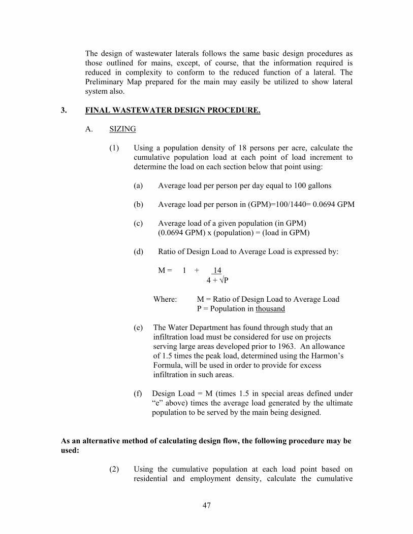
The design of wastewater laterals follows the same basic design procedures as those outlined for mains, except, of course, that the information required is reduced in complexity to conform to the reduced function of a lateral. The Preliminary Map prepared for the main may easily be utilized to show lateral system also.
3. FINAL WASTEWATER DESIGN PROCEDURE.
A. SIZING
(1) Using a population density of 18 persons per acre, calculate the cumulative population load at each point of load increment to determine the load on each section below that point using:
(a) Average load per person per day equal to 100 gallons
(b) Average load per person in (GPM)=100/1440= 0.0694 GPM
(c) Average load of a given population (in GPM)
(0.0694 GPM) x (population) = (load in GPM)
(d) Ratio of Design Load to Average Load is expressed by:
M = 1 + 14 4 + √P
Where: M = Ratio of Design Load to Average Load P = Population in thousand
(e) The Water Department has found through study that an
infiltration load must be considered for use on projects serving large areas developed prior to 1963. An allowance of 1.5 times the peak load, determined using the Harmon’s Formula, will be used in order to provide for excess infiltration in such areas.
(f) Design Load = M (times 1.5 in special areas defined under
“e” above) times the average load generated by the ultimate population to be served by the main being designed.
As an alternative method of calculating design flow, the following procedure may be used:
(2) Using the cumulative population at each load point based on residential and employment density, calculate the cumulative
47
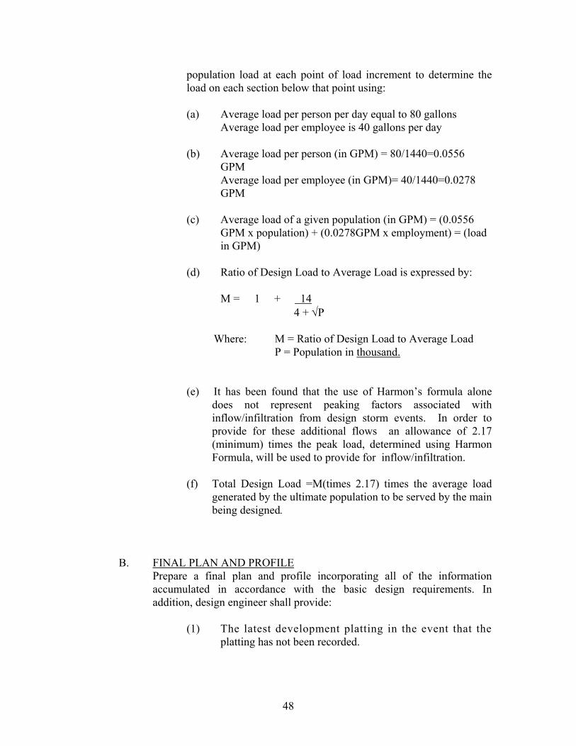
population load at each point of load increment to determine the load on each section below that point using:
(a) Average load per person per day equal to 80 gallons
Average load per employee is 40 gallons per day
(b) Average load per person (in GPM) = 80/1440=0.0556 GPM Average load per employee (in GPM)= 40/1440=0.0278 GPM
(c) Average load of a given population (in GPM) = (0.0556
GPM x population) + (0.0278GPM x employment) = (load in GPM)
(d) Ratio of Design Load to Average Load is expressed by:
M = 1 + 14 4 + √P
Where: M = Ratio of Design Load to Average Load P = Population in thousand.
(e) It has been found that the use of Harmon’s formula alone does not represent peaking factors associated with inflow/infiltration from design storm events. In order to provide for these additional flows an allowance of 2.17 (minimum) times the peak load, determined using Harmon Formula, will be used to provide for inflow/infiltration.
(f) Total Design Load =M(times 2.17) times the average load
generated by the ultimate population to be served by the main being designed.
B. FINAL PLAN AND PROFILE
Prepare a final plan and profile incorporating all of the information accumulated in accordance with the basic design requirements. In addition, design engineer shall provide:
(1) The latest development platting in the event that the platting has not been recorded.
48
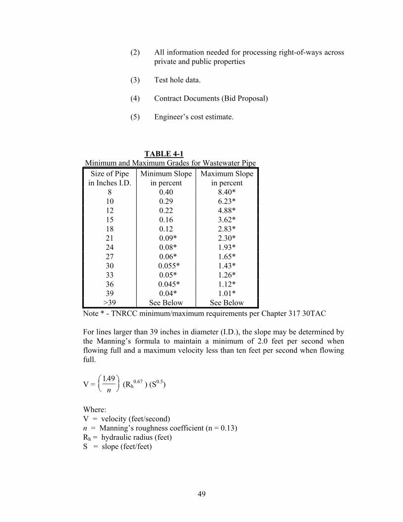
(2) All information needed for processing right-of-ways across private and public properties (3) Test hole data. (4) Contract Documents (Bid Proposal) (5) Engineer’s cost estimate.
TABLE 4-1
Minimum and Maximum Grades for Wastewater Pipe Size of Pipe
in Inches I.D. Minimum Slope
in percent Maximum Slope
in percent 8 0.40 8.40* 10 0.29 6.23* 12 0.22 4.88* 15 0.16 3.62* 18 0.12 2.83* 21 0.09* 2.30* 24 0.08* 1.93* 27 0.06* 1.65* 30 0.055* 1.43* 33 0.05* 1.26* 36 0.045* 1.12* 39 0.04* 1.01* >39 See Below See Below
Note * - TNRCC minimum/maximum requirements per Chapter 317 30TAC
For lines larger than 39 inches in diameter (I.D.), the slope may be determined by the Manning’s formula to maintain a minimum of 2.0 feet per second when flowing full and a maximum velocity less than ten feet per second when flowing full.
V = 149.
n
(Rh0.67 ) (S0.5)
Where: V = velocity (feet/second) n = Manning’s roughness coefficient (n = 0.13) Rh = hydraulic radius (feet) S = slope (feet/feet)
49
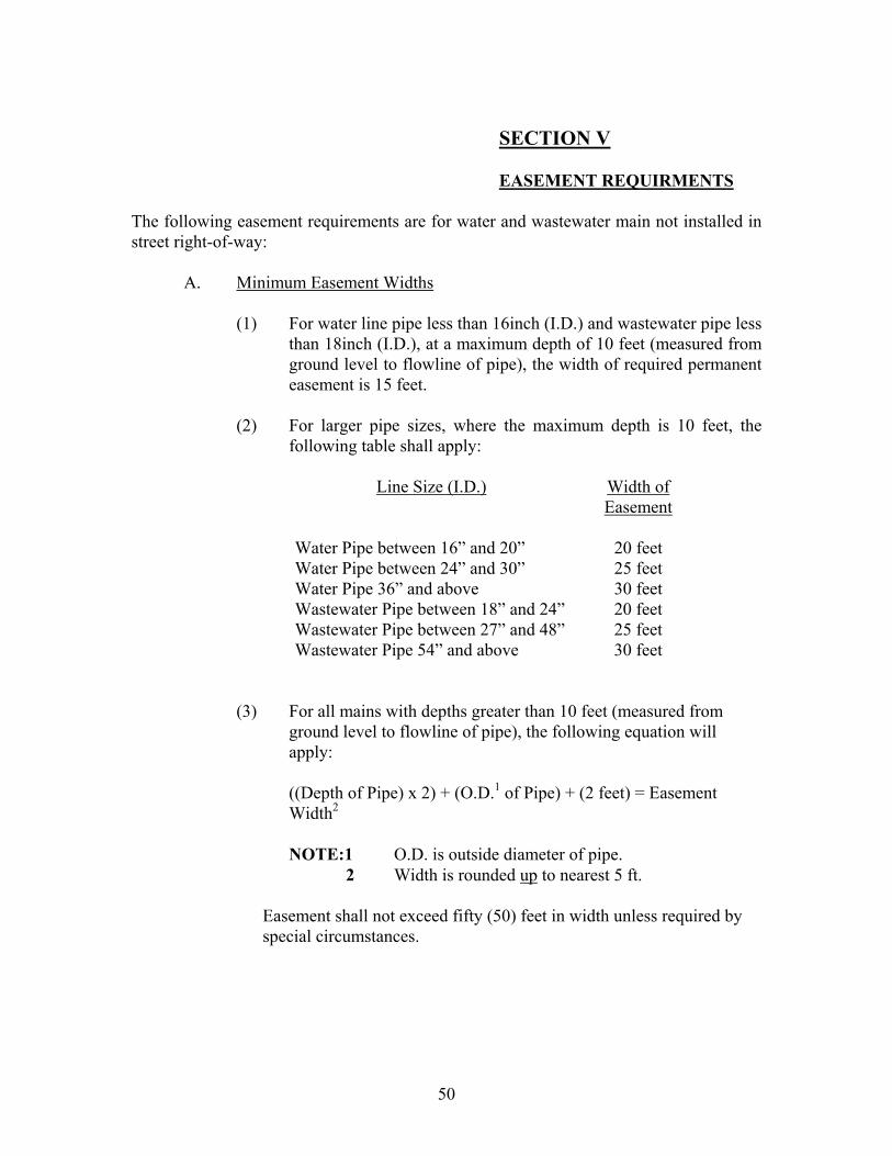
SECTION V EASEMENT REQUIRMENTS
The following easement requirements are for water and wastewater main not installed in street right-of-way:
A. Minimum Easement Widths
(1) For water line pipe less than 16inch (I.D.) and wastewater pipe less than 18inch (I.D.), at a maximum depth of 10 feet (measured from ground level to flowline of pipe), the width of required permanent easement is 15 feet.
(2) For larger pipe sizes, where the maximum depth is 10 feet, the
following table shall apply:
Line Size (I.D.) Width of Easement
Water Pipe between 16” and 20” 20 feet Water Pipe between 24” and 30” 25 feet Water Pipe 36” and above 30 feet Wastewater Pipe between 18” and 24” 20 feet Wastewater Pipe between 27” and 48” 25 feet Wastewater Pipe 54” and above 30 feet
(3) For all mains with depths greater than 10 feet (measured from ground level to flowline of pipe), the following equation will apply:
((Depth of Pipe) x 2) + (O.D.1 of Pipe) + (2 feet) = Easement Width2
NOTE:1 O.D. is outside diameter of pipe.
2 Width is rounded up to nearest 5 ft.
Easement shall not exceed fifty (50) feet in width unless required by special circumstances.
50

B. Format:
All easement instruments shall be in a standard City format. For each easement submitted, a minimum of two easement instruments with original signature(s) of the property owner(s) and notary signature/seal is required. If the easement is to be acquired by the City, a minimum of two easement instruments in a standard City format is required. All easement instruments shall be in a form acceptable to the City.
C. Temporary Construction Easements:
Approach water and/or wastewater lines or other facilities to be constructed outside the developer’s property may require additional temporary construction easements. These easements are in addition to the above listed permanent easements.
51
APPENDIX A
WATER DEPARTMENT GENERAL REQUIREMENTS
FOR DEVELOPER’S PROJECT TO GET BUILDING PERMIT OR PLAT RELEASED FOR PROJECTS OVER $ 25,000.00
WITH NO CITY PARTICIPATION***
*FOR SMALL JOBS SEE NOTE BELOW OR USE THE UNDER $25,000 REQUIREMENTS. Requirements for Civil Engineer:
2 sets of CIVIL UTILITY CONSTRUCTION PLANS and DOCUMENTS covering the scope of water and sewer work to be submitted to Water department. (Attn : Ms. Wendy Chi-Babulal.) Please advise the architect to coordinate with backflow prevention staff (Richard Munoz: 871-8375) and/or grease trap staff (Jerry Pressley: 871-8305) for potential requirements on the propose development to eliminate delay on approval of building permit. A cost estimate and exhibit prepared by the engineer must be attached to the CFA signed by the Developer.
Requirements for Developer: 1. 3 signed copies of Informal CFA from Developer (A copy is available from
Wendy Chi-Babulal, 871-7585. ATTACH A COST ESTIMATE AND 8 ½ x 11 inch EXHIBIT prepared by the engineer.). This Community Facility Agreement is an agreement between the City and the Developer to finish the job in a timely, safe, businesslike manner using a prequalified contractor**. Please include any plat numbers, or building permit numbers which we will need to release comments on at the appropriate time.
2. Developer’s Deposit This is based on the estimates on the scope of water and sewer work. It could be either 125% check (which can be handled as escrow or revenue), 100% DEVELOPER’S BOND, or 125% Escrow/ Pledge (please call Wendy Chi-Babulal @ 871-7585 For A copy.). [Completion Agreements and Letters of Credit will be accepted only after approval from the Legal Department]. Please submit the the Escrow/ Revenue Form with the 125% Cash to indicate your choice on how your money will be paid. On any of these submit aVender’s ID Form so that any Escrow, extra inspection fee or Revenue may be returned to you. A development bond copy is available from Wendy Chi-Babulal, 871-7585. important: The person signing these financial guarantees and the informal CFA must be a president or in an authority to bind the company to the conditions of the CFA. Otherwise we will need a written statement saying that person (Comptroller, Secretary of Co.,
52
Regional Mgr., etc.) has the authority to bind the company to the signed agreement.
3. 2% Inspection Fee.
This is 2% of the water and sewer estimates due for every project. **Requirements for Pre-Qualified General or Utility Contractor:
1. Certificate of Insurance. 2. Contract between the City and the Contractor 3. Maintenance Bond 4. Payment Bond 5. Performance Bond
The prequalification process takes approximately 2 weeks, so your selected contractor must start very soon on this process unless you are using a contractor who is already prequalified with the WATER DEPARTMENT. ***IF THERE IS CITY PARTICIPATION, THEN THE CFA MUST BE GENERATED BY MEETING WITH RAQUEL VELASQUEZ IN TRANSPORTATION PUBLIC WORKS , THE OFFICIAL FORMAL CFA PREPARER. A filing fee will be paid to start the formal process. After each department submits their part of the document, the formal CFA will be submitted to the City Council for approval. *NOTE: Small jobs may be submitted to the In-House Design section through Water Applications section thereby dismissing the need for the above requirements. Make application and wait for the design estimate to be finished. After payment and approval of the design by the Developer ‘s agents, the City contractor will do the utility work. Please pay any water meter deposits, water and sewer impact fees or ordinance tap fees in the Water Applications section by Development Permits. Failure to pay these may hold your building permit even though the CFA, financial guarantee, and inspection fee are in place. 2/8/2001
53

APPENDIX B
WATER DEPARTMENT
MINIMUM REQUIREMENTS FOR DEVELOPER’S PROJECT TO GET BUILDING PERMIT OR PLAT RELEASED FOR PROJECTS UNDER $ 25,000.00
These minimum requirements only apply to minor projects such as: fireline tap, or large domestic and irrigation taps. These minimum requirements does not apply to any water or sewer extension projects or any major water and sewer projects. NOTE: Small jobs may be submitted to the In-house design section through Water Applications section thereby dismissing the need for the requirements listed below. A design estimate will be prepared by them. After payment and approval of the design by the Developer‘s agents, the City contractor will do the utility work. This choice is available on small jobs and in the long run is faster and cheaper. (A) Submit a request to WATER APPLICATIONS for the design estimate to be done. (B)Approve and pay for job after design estimate finished (1-2 weeks). (C) The job is put on the list for the City contracted Contractor to do within 1-2 months( If the distance from the City main to the building is 100’ or less then the vault for the double detector check can go in the building and save the expense of a vault on small water fireline jobs.. Requirements for Civil Engineer:
2 sets of CIVIL UTILITY CONSTRUCTION PLANS and DOCUMENTS covering the scope of water and sewer work to be submitted to Water department. (Attn : Ms. Wendy Chi-Babulal.) Please advise the architect to coordinate with backflow prevention staff (Richard Munoz: 871-8375) and/or grease trap staff (Jerry Pressley: 871-8305) for potential requirements on the propose development to eliminate delay on approval of building permit. A cost estimate and exhibit prepared by the engineer must be attached to the CFA signed by the Developer.
Requirements for Developer: 1. 3 signed copies of Informal CFA from Developer (A copy is available from
Wendy Chi-Babulal, 871-7585. Attach a cost estimate and exhibit prepared by the engineer.) This is an agreement between the city and the Developer
2. Developer’s Deposit This is based on the estimates on the scope of water and sewer work. It could be either 125% check , 100% DEVELOPER’S BOND, or 125% Escrow/ Pledge (please call Wendy Chi-Babulal @ 871-7585 For A copy.). [Completion Agreements and Letters of Credit will be accepted only after approval from the Legal Department]. (please call Wendy Chi-Babulal @ 871-7585 For a Development Bond copy.) Please submit the Vender’s ID Form and the Escrow/Revenue Form with the 125% Cash.
54

Important: The person signing these financial guarantees and the informal CFA must be a president or in an authority to bind the company to the conditions of the CFA. Otherwise we will need a written statement saying that person (Comptroller, Secretary of Co., Regional Mgr., etc.) has the authority to bind the company to the signed agreement.
3. 2% Inspection Fee. This is 2% of the water and sewer estimates.
Requirements for Prequalified** General or Utility Contractor:
1. Certificate of Insurance. 2. Contract between the City and the Contractor 3. Maintenance Bond
**See rules for Prequalification Requirements for Contractors. 2/8/2001
55
APPENDIX C
CITY OF FORT WORTH ADOPTED PROCEDURE CHANGES FOR EXPEDITING
REVIEW AND APPROVAL OF PLANS FOR COMMUNITY FACILITIES CONTRACTS
1. Once the preliminary plat approval is obtained from the Plan Commission, the planning
conference should be scheduled with the appropriate level of representation at a common meeting from: the Developer’s engineers, Public Works Department, Water Department, Traffic Engineering Department, Park and Recreation Department where parks are involved. To determine:
a) What engineering information is needed but not of record (such as actual depth and
location of water mains to be extended to serve the proposed development) to expedite plan preparation in which the affected department is expected to develop and provide to the consultant.
b) What portions of the work should be scheduled first, second, etc.? c) Can combination of construction of facilities benefit the development, such as one
contract for water, wastewater, and storm drain facilities?
d) Is there a compelling need of the developer that warrants establishing a deadline for completion of one or more of the facilities?
e) Should the development be segmented for optimum scheduling of community facilities
construction?
f) Intersection studies including median, widths, channelization, etc. should be determined initially.
g) Usual items of the development and cost participation would be clarified.
The Developer’s engineer shall notify the Development Coordinator of the time he wishes the meeting to be held. The Development Coordinator shall set up the meeting with the appropriate departments. The Engineer shall provide for the meeting the preliminary plat, concept plan if any, and any other data available. Minutes of the meeting would be prepared and distributed to all concerned that would outline the decisions made at the meeting. 2. The Developer’s consulting engineering firm should begin engineering toward final engineering plans immediately. The highest priority should be give to development and approval of street trades, width and configuration, and drainage requirements. 3. Preliminary layouts (working drawings) of water, wastewater, storm drain, street lights, and street
facilities should be developed and reviewed with the respective department’s engineering representatives including Traffic Engineering as soon as street grading studies permit. Technical concept conferences with the technical personnel may be scheduled by phoning the respective departments and setting up a date for the meeting. Tentative return dates will be determined at the time of submittal.
4. Draft plans and specifications (perhaps in pencil) for water, wastewater, storm drain, and street
construction should be prepared and submitted as soon as possible after the preliminary review to
56
assist in identification and treatment of unusual project requirements and special conditions. Street construction plans should also be reviewed by the Traffic Engineering representative. Tentative return dates will be determined at the date of submittal. The Developer’s engineer is encouraged to discuss technical problems on the working drawings with the City staff as the need may arise.
NOTE: Steps 3 and 4 above may be combined with the specific consent of the
department’s engineering representative affected. 5. Final plans and specifications developed along the above guidelines should be ready for final
review and approval upon submittal. The final plans should be submitted for review as a package, which would include water, wastewater storm drain, paving, and final plat. One set of final plans should be sent to all departments affected at the time of submittal. The cover sheet for signature would be submitted to the Park Department first, if there are peaks involved, to the Traffic Engineering Department second, and the Water Department third, and to the Public Works Department last. The Developer shall secure a receipt of the date the plans and specifications are delivered to the various departments. A receipt for the cover sheet shall also be obtained.
6. If possible the affected department would sign the cover sheet for the plans and specifications and
if there are any corrections to be made, if minor, a list of conditions will be supplied both to the developer and his engineer in writing. Should there be a discrepancy or omission of which the affected department considers severe to warrant returning the plans with noted corrections and/or questions prior to signing, this would be done by calling the developer’s engineering consultant and holding a conference during with the affected department would explain the problems that needed to b resolved in order to sign the plans. The department would keep each other informed of any conditions of approval and/or changes required.
7. Upon approval of the plans, the developer could advertise and receive bids. 8. The affected departments would prepare a community facilities contract and submit same to the
Development Coordinator for Council approval. After execution of the Community Facilities contract, the final plat could then be filed for record.
9. Upon receipt of bid tabulations and the approval of the community facilities contract, the developer would be notified by the various affected departments as to their approval of the developer’s request to award the contract.
57

APPENDIX D
PREQUALIFICATION REQUIREMENTS FOR CONTRACTORS
1. Financial Statement prepared by CPA 2. References of Related Work a. Project Name b. Contact Person and Number c. Amount of Contract d. Size of Pipe Installed e. Date of Project 3. Equipment Schedule - equipment related to the bid job own by the company MAIL TO : Engineering Manager Fort Worth Water Engineering P.O. Box 870 Fort Worth, TX 76101- 0870
58
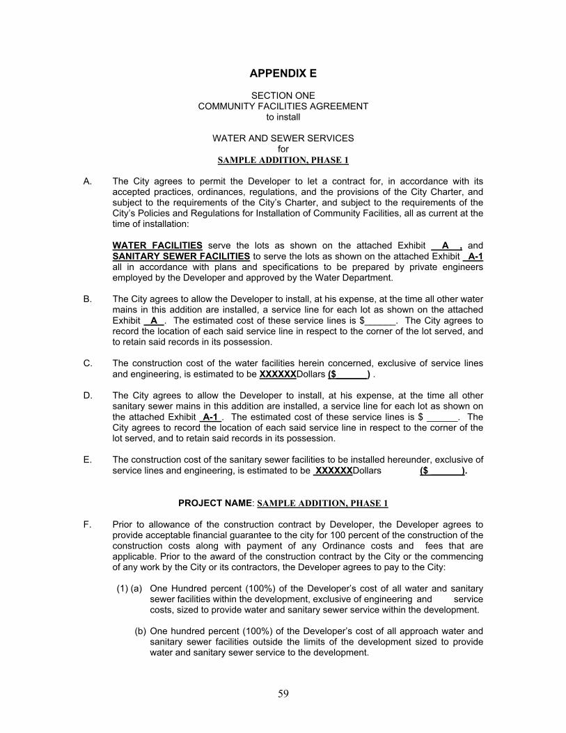
APPENDIX E
SECTION ONE COMMUNITY FACILITIES AGREEMENT
to install
WATER AND SEWER SERVICES for
SAMPLE ADDITION, PHASE 1 A. The City agrees to permit the Developer to let a contract for, in accordance with its
accepted practices, ordinances, regulations, and the provisions of the City Charter, and subject to the requirements of the City’s Charter, and subject to the requirements of the City’s Policies and Regulations for Installation of Community Facilities, all as current at the time of installation:
WATER FACILITIES serve the lots as shown on the attached Exhibit A , and
SANITARY SEWER FACILITIES to serve the lots as shown on the attached Exhibit A-1 all in accordance with plans and specifications to be prepared by private engineers employed by the Developer and approved by the Water Department.
B. The City agrees to allow the Developer to install, at his expense, at the time all other water
mains in this addition are installed, a service line for each lot as shown on the attached Exhibit A . The estimated cost of these service lines is $______. The City agrees to record the location of each said service line in respect to the corner of the lot served, and to retain said records in its possession.
C. The construction cost of the water facilities herein concerned, exclusive of service lines
and engineering, is estimated to be XXXXXXDollars ($______) . D. The City agrees to allow the Developer to install, at his expense, at the time all other
sanitary sewer mains in this addition are installed, a service line for each lot as shown on the attached Exhibit A-1 . The estimated cost of these service lines is $ ______. The City agrees to record the location of each said service line in respect to the corner of the lot served, and to retain said records in its possession.
E. The construction cost of the sanitary sewer facilities to be installed hereunder, exclusive of
service lines and engineering, is estimated to be XXXXXXDollars ($ ______).
PROJECT NAME: SAMPLE ADDITION, PHASE 1
F. Prior to allowance of the construction contract by Developer, the Developer agrees to
provide acceptable financial guarantee to the city for 100 percent of the construction of the construction costs along with payment of any Ordinance costs and fees that are applicable. Prior to the award of the construction contract by the City or the commencing of any work by the City or its contractors, the Developer agrees to pay to the City:
(1) (a) One Hundred percent (100%) of the Developer’s cost of all water and sanitary
sewer facilities within the development, exclusive of engineering and service costs, sized to provide water and sanitary sewer service within the development.
(b) One hundred percent (100%) of the Developer’s cost of all approach water and
sanitary sewer facilities outside the limits of the development sized to provide water and sanitary sewer service to the development.
59

(c) One hundred percent (100%) of the Developer’s cost of any approach water
main facility or water facility within the development that is 8-inches in size for non-industrial development and 12-inches in size for industrial development.
(d) One hundred percent (100%) of the Developer’s cost of any approach sanitary
sewer main facility or sanitary sewer facility within the development that is 8-inches in size.
(2) An additional ten percent (10%) of the total of the Developer’s cost of these
water and sanitary sewer facilities, exclusive of cost of service lines, is required for design engineering if such engineering is performed by the City at the Developer’s request.
(3) One hundred percent (100%) of the Developer’s cost of all service lines,
estimated under B and D above, in accordance with the provisions of the current Fort Worth City Code.
(4) A construction Inspection Fee equal to two (2%) of the Developer’s actual cost
share of the construction cost (including all services) of the water and/or sanitary sewer facilities.
G. The distribution of estimated construction cost between the City and the Developer, as
per paragraph F above, for all water and sanitary sewer facilities to be constructed hereunder is estimated as follows:
PROJECT NAME: SAMPLE ADDITION, PHASE 1
(1) WATER FACILITIES : Estimated
Developer Cost
Estimated City Cost
Total Cost
(a) Mains, Within Development $ 0.00 $ 0.00 $ 0.00
Approach $ 0.00 $ 0.00 $ 0.00 (b) Easements* $ 0.00 $ 0.00 $ 0.00 (c) Services (0-1”) $ 0.00 $ 0.00 $ 0.00 Sub-Totals, Water $ 0.00 $ 0.00 $ 0.00
60
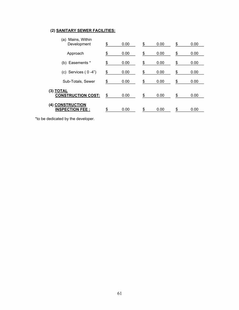
(2) SANITARY SEWER FACILITIES:
(a) Mains, Within
Development $ 0.00 $ 0.00 $ 0.00 Approach $ 0.00 $ 0.00 $ 0.00 (b) Easements * $ 0.00 $ 0.00 $ 0.00 (c) Services ( 0 -4”) $ 0.00 $ 0.00 $ 0.00 Sub-Totals, Sewer $ 0.00 $ 0.00 $ 0.00 (3) TOTAL CONSTRUCTION COST: $ 0.00 $ 0.00 $ 0.00 (4) CONSTRUCTION INSPECTION FEE : $ 0.00 $ 0.00 $ 0.00
*to be dedicated by the developer.
61
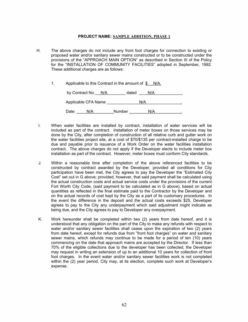
PROJECT NAME: SAMPLE ADDITION, PHASE 1
H. The above charges do not include any front foot charges for connection to existing or
proposed water and/or sanitary sewer mains constructed or to be constructed under the provisions of the “APPROACH MAIN OPTION” as described in Section III of the Policy for the “INSTALLATION OF COMMUNITY FACILITIES” adopted in September, 1992. These additional charges are as follows:
1. Applicable to this Contract in the amount of $ N/A.
by Contract No. N/A dated N/A Applicable CFA Name N/A . Date: N/A Number N/A .
I. When water facilities are installed by contract, installation of water services will be
included as part of the contract. Installation of meter boxes on those services may be done by the City, after completion of construction of all relative curb and gutter work on the water facilities project site, at a cost of $70/$135 per contract-installed charge to be due and payable prior to issuance of a Work Order on the water facilities installation contract. The above charges do not apply if the Developer elects to include meter box installation as part of the contract. However, meter boxes must conform City standards.
J. Within a reasonable time after completion of the above referenced facilities to be
constructed by contract awarded by the Developer, provided all conditions for City participation have been met, the City agrees to pay the Developer the “Estimated City Cost” set out in G above; provided, however, that said payment shall be calculated using the actual construction costs and actual service costs under the provisions of the current Fort Worth City Code, (said payment to be calculated as in G above), based on actual quantities as reflected in the final estimate paid to the Contractor by the Developer and on the actual records of cost kept by the City as a part of its customary procedures. In the event the difference in the deposit and the actual costs exceeds $25, Developer agrees to pay to the City any underpayment which said adjustment might indicate as being due, and the City agrees to pay to Developer any overpayment.
K. Work hereunder shall be completed within two (2) years from date hereof, and it is
understood that any obligation on the part of the City to make any refunds with respect to water and/or sanitary sewer facilities shall cease upon the expiration of two (2) years from date hereof, except for refunds due from ”front foot charges” on water and sanitary sewer mains, which refunds may continue to be made for a period of ten (10) years commencing on the date that approach mains are accepted by the Director. If less than 70% of the eligible collections due to the developer has been collected, the Developer may request in writing an extension of up to an additional 10 years for collection of front foot charges. In the event water and/or sanitary sewer facilities work is not completed within the (2) year period, City may, at its election, complete such work at Developer’s expense.
62
L. It is further agreed and understood that any additional payment required of Developer is to cover only such additional work and/or materials as may be made necessary by conditions encountered during construction, and shall not include any change in scope of the project.
RECOMMENDED:
____________________________ Dale A. Fisseler, P. E. Director Water Department
_____________________________ Date
63
APPENDIX F
INFORMAL DEVELOPER AGREEMENT TO BE EXECUTED BY
DEVELOPERS WISHING TO LET THEIR OWN CONTRACTS FOR CONSTRUCTION OF WATER AND/OR
WASTEWATER FACILITIES The undersigned DEVELOPER has familiarized himself with the City of Fort Worth’s “Policy for the Installation of Community Facilities” governing water and/or wastewater facility installations and fully understands all the provisions, terms and conditions of that policy, and wishes to exercise the option contained in that policy permitting a DEVELOPER to let his own contracts for construction of such water or wastewater facilities. In addition to all other requirements of the City’s Policy for the Installation of Community Facilities, the DEVELOPER specifically agrees to follow the procedures set forth below: 1. To employ a construction contractor who is approved by the Director of the Water Department. The
requirements for such approval shall include, but not be limited to:
a. The Contractor proposed to perform the work hereunder shall be prequalified as a bidder in the same manner that the City Water Department prequalifies bidders for City let contracts. The prequalification requirements for City let Water and Wastewater contracts are as follows:
A current financial statement, and acceptable experience record, and an acceptable equipment schedule must be filed with the Director of the Water department at least one week prior to the hour for opening bids. The financial statement required shall have been prepared by an independent certified public accountant or an independent public accountant holding a valid permit issued by an appropriate state licensing agency, and shall have been so prepared as to reflect the current financial status. This statement must be current and not more than one (1) year old. In the case that a bidding date falls within the time a new statement is being prepared, the previous statement shall be updated by proper verification. Proposals submitted by a prospective bidder who has not fulfilled the above requirements shall be returned unopened. Liquid Assets in the amount of ten (10%) percent of the estimated project cost will be required. For an experience record to be considered to be acceptable for a given project, it must reflect the experience of the firm seeking qualifications in work of both the same nature and magnitude as that of the project for which bids are to be received, and such experience must have been on projects completed not more than five (5) years prior to the date on which bids are to be received. The Director of the Water Department shall be the sole judge as to the acceptability of experience for qualification to bid on any Fort Worth Water Department projects. The prospective bidder shall schedule the equipment he has available for the project and state that he will rent such additional equipment as may be required to complete the project on which he submits a bid.
b. The Contractor shall meet the City’s requirements for being licensed and bonded to do work in public streets.
2. To require the Contractor to furnish the Water Department performance bond and payment bond in the name of
the City and the Developer, and a maintenance bond in the name of the City on forms provided by the City, for 100% of the contract price of the facility, said performance, payment, and maintenance bonds to be furnished to the City before work is commenced.
2. To deposit with the Water Department an amount equal to 10% of the contract price for all facilities to be constructed
by the Contractor employed by the DEVELOPER, prior to commencing of any construction work. Said amount shall be for the engineering services to be performed by the Water Department, if the Water Department has prepared the plans and specifications for the work to be done. In this regard, if the DEVELOPER wishes to employ his own engineers to prepare plans and specifications, he may do so, subject to the requirements of City’s Policy for the Installation of Community Facilities (including waiver of all engineering charges) and to the further requirement that:
a. Written approval by the Director of the Water Department of the plans and specifications so prepared
shall be obtained prior to the employment of any contractor to perform the work contemplated.
b. Approved plans and specifications shall be furnished to the Engineering Division of the Water Department prior to a Confirmation of Award of Contract being issued by the Engineering Division.
64

4. To require the Contractor to give 48 hours notice to Director of the Water Department prior to commencing
construction of the facility or facilities so that inspection personnel will be available.
5. To make this agreement, as well as the General Specifications of the Fort Worth Water Department (except as they are modified by the plans and specifications approved by the Director of the Water Department to govern construction of the work) an integral part of any contract with a contractor to construct any or all of the facilities involved.
6. To require the Contractor to allow the construction to be subject to inspection at any and all times by Water
Department inspection forces and not to install any Wastewater or water facility unless an inspector designated by the Director of the Water Department is present and gives his consent to proceed.
6. To require the Contractor to have such laboratory tests made as the City may require. 7. To secure approval by the Director of the Water Department of any and all partial and final payments to the
Contractor, such approval to pertain only to satisfactory completion of the work for which payment is made and not to constitute approval of the quantities on which payment is based.
8. To delay connection of any buildings to service lines of wastewater and water mains until such wastewater,
water mains, and services have been completed to the satisfaction of the Water Department. 10. To furnish simultaneously with the execution of the construction contract let by the Developer, performance and
payment bond in the name of the City of one hundred percent (100%) of the estimated contract cost of the related water and/or wastewater construction, as stated in the construction contract, to guarantee timely payments to the Contractor for completed work and/or to guarantee satisfactory performance of this agreement and substantial completion of the water and sewer facilities to be installed. If the deposit is in the form of cash, the deposit shall be for one hundred twenty five percent (125%) of the estimated developer’s share of the cost of the Water and Wastewater facilities. In addition, developer shall pay to the City in cash for the construction inspection fee equal to two percent (2%) of the developer’s share of the construction cost of related water and/or wastewater facilities as stated in the construction contract.
11. Work hereunder shall be completed within two (2) years from date hereof, and it is understood that any
obligation on the part of the City to make any refunds with respect to water and/or wastewater facilities shall cease upon the expiration of two (2) years from date hereof, except for refunds due from “front foot charges” on water and wastewater mains, which refunds may continue to be made for a period of ten (10) years commencing on the date that approach mains are accepted by the Director. If less than 70% of the eligible collections due to the developer have been collected, the Developer may request in writing an extension of up to an additional 10 years for collection of front charges.
The DEVELOPER further covenants and agrees to, and by these presents does hereby, fully indemnify, hold harmless and defend the City, its officers, agents and employees from all suits, actions or claims of any character, whether real or asserted, brought for or on account of any injuries or damages sustained by any persons (including death) or to any property, resulting from or in connection with the construction, design, performance or completion of any work to be performed by said DEVELOPER, his contractors, subcontractors, officers, agents or employees, or in consequence of any failure to properly safeguard the work, or on account of any act, intentional or otherwise, neglect or misconduct of said DEVELOPER, his contractors, sub-contractors, officers, agents or employees, whether or not such injuries, death or damages are caused, in whole or in part, by the alleged negligence of the City of Fort Worth, its officers, servants, or employees. It is expressly understood and agreed by the parties hereto that execution of this agreement does not bind the City of Fort Worth to participate in or contribute to the cost of any of the improvements described herein; nor shall the City of Fort Worth be responsible or liable for any portion of the costs incurred by the developer, its officers, agents, employees, contractors or sub-contractors for the design and construction of the improvements described herein, unless and until the parties hereto execute a Formal Community Facilities Agreement, duly authorized by the City Council at a regular meeting, signed by the City Manager, and providing for the City’s participation in the costs of said improvements.
This agreement pertains to water and/or wastewater facilities required to serve the following described property:
65

________________________________________________________
________________________________________________________
________________________________________________________
ACCEPTED FOR FORT WORTH _______________________________ WATER DEPARTMENT: DEVELOPER ________________________________ By:_____________________________
DATE:___________________________ ________________________________ DATE:___________________________ Water Project # P____-___________________ Contract Amount for Water Improvement $__________________
(See Attached Exhibit “A” for Water Layout and Cost Estimate)
Sewer Project # P____-___________________ Contract Amount for Sewer Improvement $__________________
(See Attached Exhibit “B” for Sewer Layout and Cost Estimate)
Related Plat Case #___________________ Related Building Permit #________________________ (If Applicable) (If Applicable) (Need 3 copies with original signature on each.) Mail to: Wendy Chi-Babulal
Water Engineering 1000 Throckmorton
Fort Worth, TX 76101
66

67

68

69
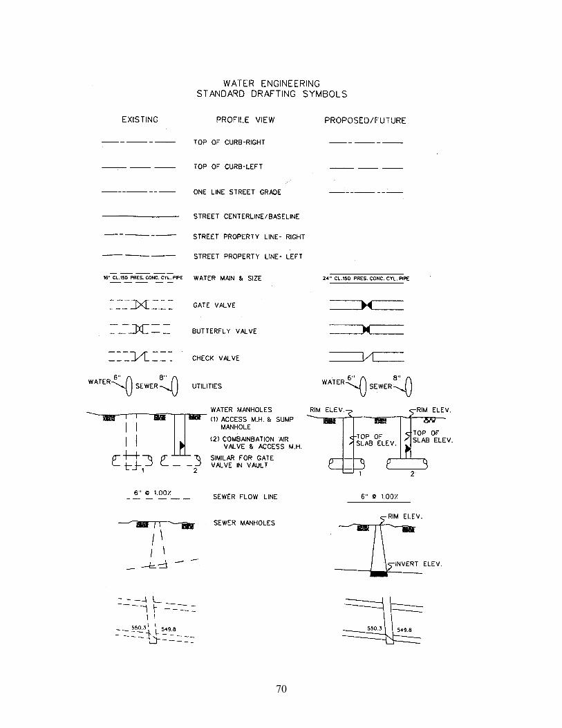
70
APPENDIX H
BACKFLOW PROTECTION FOR FIRELINES 1. Purpose
In the interest of protecting the public’s potable water supply from possible contamination, effective Jan. 1, 1996, the City of Fort Worth Water Department will require backflow protection on all new fireline installations. As in other situations encountered in cross-connection control the degree of backflow protection necessary for a particular fire protection system will depend on specific conditions present. Pressure losses across backflow prevention assemblies must be accommodated in the design or redesign of the fire protection system if it is to function properly. This factor is particularly important when redesigning existing fire protection systems. All backflow assembles will be U.L. listed and U.S.C. approved. Backflow Prevention Assemblies detailed herein shall be installed/constructed with the provisions set forth in the City of Fort Worth Water Dept. Ordinance on Backflow Prevention.
2. Classification and requirements for Backflow Protection:
TYPE OF FIRELINE REQUIRED PROTECTION A. Fireline with no chemical Double Check additive and no additional Detector Assembly water supply B. Fireline with fire hydrant, Double Check no chemical additive and Detector Assembly additional water supply C. Fire protection system with Air Gap Separation or utilizing chemical additives Reduced Pressure Principle Assembly D. Fire protection system with Air Gap Separation or access to an auxiliary water Reduced Pressure Principle supply Assembly
E. Firelines tied into domestic lines Double Check that are already metered Systems with only a single chemical loop, e.g., anti-freeze loop, foam, etc., may install the backflow protection on the loop, however, an expansion chamber will be
71

recommended to be installed to compensate for thermal expansion. Systems containing more than one loop must provide backflow protection for the entire system. Existing chemical loops and systems with access to an auxiliary water supply shall be retrofitted with approved backflow protection. 3. Backflow Preventive Approval
Backflow preventer approval must be obtained from the City of Fort Worth Water Department, Cross Connection Section, prior to installation. The installation shall conform to the attached guidelines. Direct any questions or comments to the Cross Connection Section (817) 871-8375.
A. To install the Backflow Assembly inside the building, the distance from tap to
assembly shall mot be over 100 feet, branch lines from tap to assembly are not allowed.
B. For firelines over 100 feet from tap to assembly, the assembly shall be installed in an approved vault, or above ground (type of assembly) at property line. Install to meet City testing procedures. The assembly will be located on private property, not in an easement or right of way.
C. All installations shall be horizontal unless approved by Administrative
Authority. To be installed in the vertical position the assembly has to be:
1. Approved by USC for vertical 2. Spring loaded checks 3. Install in up flow position 4. Approved by Administrative Authority
(Call Roger Q. Hauser (817) 871-8375) 4. Testing:
A. New Firelines: Call R. Hauser at (817) 871-8375 to set up backflow test. Mr. Hauser will coordinate with valve section in loading line.
B. Existing Fireline: Call B. Ramon (817) 212-2624 to set up valve crew to turn
off and on water for repairs, etc. Note: Only City employees can operate water main valves.
C. City of Fort Worth will test all new assemblies at installation. D. Backflow assemblies shall meet testing specifications for distance from wall
to floor. *See vault details. E. Backflow assemblies inside buildings, more than 5 foot above floor level shall
have an approved permanent platform for testing and maintenance.
72

5. Existing Firelines
A. Retrofitting existing firelines is necessary if there is a chemical additive used, or if there is alternate water tied into system. This is a HIGH HAZARD RETROFIT.
B. Retrofitting Low Hazard existing fireline not required unless size of main is
changed or replaced to accommodate pressure loss for additional sprinkler heads.
6. Vault Details Attached: A. Vaults and Lids to be equivalent to details.
73

74

75

76

Types of Registered Testers with the City of Fort Worth
Fire Line Testers – (full time employee)
• Can test and repair all assemblies, F.L.’s, Domestic, Irrigation • Can replace assemblies on F.L.’s systems • Can replace assemblies on domestic only if a Master Plumber
(must pull permit!) Master Plumber Tester –
• Can replace only on Domestic & Irrigation • Can test and repair only on Domestic & Irrigation
(must pull permits for replacements) Irrigation Tester –
• Can replace assemblies on Irrigation ONLY (must pull permit!) • Can repair and test on domestic & Irrigation
General Tester –
• Can repair and test domestic & Irrigation only
77
Appendix I DEFINITIONS APPROACH MAIN OR BOUNDARY SERVICE CONNECTIONS: Service Connections located outside
the development for which the “approach main” or “boundary facility” is constructed, and connected directly to the “approach main” or “boundary facility”.
APPROACH MAINS:
1. WATER: The off site main required to connect a development to a source of amply supply. It shall be not less than 8-inches in diameter and of a size large enough to serve both the development for which the service is requested and adjoining areas, as determined by the Water Department.
2. WASTEWATER: The wastewater main required by the Water Department to serve the
entire drainage area in which it is to be constructed, both inside and outside of a developer’s property, under ultimate development conditions, to connect wastewater main facilities to the City’s wastewater system.
ARTERIAL ROADWAY OR MAJOR THOROUGHFARE: Part of the roadway system that serves as a principal network for the through traffic flow. Such roadways connect areas of principal traffic generation and highways entering the city.
BACK LOT: Residential lot abutting two streets, but facing on the streets not being
improved. BORDER STREET: A street, which divided properties under separate ownership. CCN or CERTIFICATE OF CONVENIENCE AND NECESSARY:CCN/Certificate Of Convenience and
Necessary for Water or Wastewater Utility Service is issued by the Texas Natural Resources Conservation Commission (TNRCC) to a public or private organization to provide exclusive water or wastewater service to a defined area.
CITY Shall mean the City of Fort Worth. COLLECTOR STREET: The distributor and collection roadways. Roadways used mainly for traffic
movements within development, commercial and industrial areas. COMMERCIAL DEVELOPMENT: This designation shall apply to all properties other that residentially or
industrially zoned properties, which require extension of community facilities due to new construction or expansion of existing improvements on the property.
COMMERCIAL ESTABLISHMENT: Any establishment other that one or two family residence or
industrial. COMMERCIAL PROPERTY: Any property not included in the definition of residential (one or two
family) zoned property or industrial zoned property. CONSTRUCTION ENGINEERING: shall consist of the following:
a. The setting of line and grade stakes from the approved plans.
78
b. Necessary laboratory tests to assure compliance with plans and specifications. c. Field inspection to assure compliance with plans and specifications. d. Review and approval of Change Orders submitted by the design engineer. e. Preparation of monthly estimates and final payments to the construction contractor if the
contract is awarded by the City. f. Final inspection for acceptance of project by City.
CURBLINE Shall mean an imaginary vertical line that intersects the back of the curb of the existing
or proposed street. DEDICATED STREET OR ALLEY: Any street of alley for which right-of way has become public
property through platting, deed, or public usage as defined by law. DESIGN ENGINEERING: Consisting of all necessary studies, tests, preliminary plans, etc., necessary to
the preparation of complete plans, specifications, and contract documents meeting the approval of the Engineering Department Director
DEVELOPER: 1) Any type of new water or wastewater customer other that a “single
customer”. 2) The owner of a tract of land which has been subdivided or is being subdivided.
EXISTING DEVELOPED RESIDENTIAL AREA: This designation shall apply to defined areas in
which as least 51 percent of the lots of record already have existing improvements and in which a community facility is required for the benefit of the areas as a whole.
FRONT FOOT CHARGES:
a. WATER: The charge made for a connection to or an extension from a water main, in
addition to the regular tap or service connection fee or impact fees, based on the front footage measurement of the property to be served. The amount of the front foot charge shall be established by ordinance.
b. WASTEWATER: The charge made for a connection to or an extension from a
wastewater main, in addition to the regular service connection fee or impact fees, based on the front footage of the property served. The amount of the front foot charge shall be established by ordinance.
FRONT FOOTAGE: The number of linear feet in that potion of a property boundary abutting a street,
alley, or easement containing a wastewater or water facility for which front foot charge are collected for connection.
In the case of an easement, crossing the property, containing a wastewater main for which front foot charges are to collected, the “boundary” on which the front foot charge is to be based shall be the length of the wastewater main within the limits of such property, measured along the center line of such wastewater main.
For water and wastewater facilities in abutted streets, alleys and easements, the front footage to be used in the application of front foot charges shall be determined as follows: a). Where the property served is rectangular, the front foot
charge shall be based on the lesser of the following: 1). Front footage shall be taken as the actual linear feet abutting a
street, alley or easement containing a wastewater or water facility serving the property; or
79

2). Front footage shall be computed as one-sixth of the perimeter
of such property.
b). Where the property is irregular in shape, the front footage shall be computed as one-sixth of the perimeter of such property.
c). On property which is rectangular in shape and has more than one
boundary abutting a street, alley or easement containing a wastewater or water facility serving the property, only the boundary across which the connection is affected will be used in determining front foot charges.
INDUSTRIAL DEVELOPMENT: This designation shall apply to all industrially zoned properties, which
require extension of community facilities due to new construction or expansion of existing improvements on the property.
INDUSTRIAL PROPERTY: Any property that is industrial zoned. IRREGULAR SHAPED LOT: A lot, either residential or commercial which has an irregular shape
(not rectangular), such as a triangle, etc. LOCAL OR MINOR STREET: Roadways used primarily for direct access to residential, commercial,
industrial, or other abutting property. Does not include roadways carrying through traffic. NEW STREET CONSTRUCTION: Paving of a street that has not previously been paved, or
which has been surfaced, but which is not on City grade. NON-CONFORMING USE: A use of property permitted in a particular zoning because such use
was being made of the property at the time of the zoning or change in zoning ordinance. NON-PROFIT PROPERTY: Any property such as churches, schools, etc., which are carried as
exempt on City tax rolls. ON-SITE MAINS:
a. An on-site water main is one that provides service within a development or subdivision. Water
b. Wastewater An on-site wastewater main is one designated to serve the entire
drainage area in which it is to be constructed, both inside and upstream from all or part of a developer’s property, under ultimate development conditions, but which is located entirely within the limits of the development.
OPEN STREET OR ALLEY: Any street or alley for which the right-of-way had become public
property through platting, deed, or public usage as defined by law, and is presently being used by vehicular traffic.
OWNER-OCCUPPIED RESIDENCE: A building used as an actual residence of the owner, with the only
commercial enterprise being rental of one part of a duplex or one room of the building for residential purposes.
80
RESIDENTIAL DEVELOPMENT: Any platted residential property along a street where the greater portion of the property footage between two intersecting streets is owned by the individual or firm developing all or any part of the lots: or nay new residential platting.
RESIDENTIAL PROPERTY: Property zoned either “A” one-family or “B” two-family residential. SERVICE CONNECTIONS:
a. Water The connection between a water main and the water meter through which a given property is supplied with water.
b. Wastewater The portion of the house wastewater main located in the roadway of a
public street between the main or lateral in such street and the point approximately three (3) feet behind the curb line of such public street nearest to the site to be served, or to that portion of the house wastewater main located in a public alley, or to the tap and test tee installed for a connection to a wastewater main located in the parkway of a public street or in an easement.
SIDE LOT: Residential property abutting two streets at their intersection, with the longer street
frontage being the side of the lot. SINGLE CUSTOMER: An existing occupied residential establishment or an existing commercial
establishment not presently connected to the City’s water and/or wastewater systems STREET: Property dedicated for public’s use for vehicular and/or pedestrian traffic. STREET RECONSTRUCTION: Widening and/or reconstruction of an existing street, which has an
existing, surface on City grade. UNOPENED STREET OR ALLEY: Ant dedicated street or alley, which is not being used by vehicular
traffic.
81

82