
PolaRxS SBF Reference Guide - UNB
179
PolaRxS SBF Reference Guide Applicable to version 2.9.0 of the GNSS Firmware PolaRxS SBF Reference Guide for version 2.9.0 of the GNSS Firmware 1
Transcript of PolaRxS SBF Reference Guide - UNB

PolaRxS SBF Reference Guide
Applicable to version 2.9.0 of the GNSS Firmware
PolaRxS SBF Reference Guide for version 2.9.0 of the GNSS Firmware 1

PolaRxS SBF Reference Guide
April 24, 2015
Applicable to version 2.9.0 of the GNSS Firmware
© Copyright 2000-2015 Septentrio nv/sa. All rights reserved.
Septentrio Satellite NavigationGreenhill Campus, Interleuvenlaan 15GB-3001 Leuven, Belgium
http://[email protected]: +32 16 300 800Fax: +32 16 221 640
PolaRxS SBF Reference Guide for version 2.9.0 of the GNSS Firmware 2

LIST OF CONTENTS
List of Contents
CONTENTS 3
LIST OF ACRONYMS 4
1 INTRODUCTION 71.1 Scope. . . . . . . . . . . . . . . . . . . . . . . . . . . . . . . . . . . . . . . . . . . . . . . . . . . . . . . . . . . . . . . . . . . . . . . . . . . 71.2 Typographical Conventions . . . . . . . . . . . . . . . . . . . . . . . . . . . . . . . . . . . . . . . . . . . . . . . . . . . 71.3 Change Log . . . . . . . . . . . . . . . . . . . . . . . . . . . . . . . . . . . . . . . . . . . . . . . . . . . . . . . . . . . . . . . . . . . . 7
2 SBF OUTLINE 92.1 SBF Block Header Format . . . . . . . . . . . . . . . . . . . . . . . . . . . . . . . . . . . . . . . . . . . . . . . . . . . . 92.2 List of SBF Block Names and Numbers . . . . . . . . . . . . . . . . . . . . . . . . . . . . . . . . . . . . . 92.3 SBF Block Time Stamp (TOW and WNc) . . . . . . . . . . . . . . . . . . . . . . . . . . . . . . . . . . . . 122.4 Sub-blocks . . . . . . . . . . . . . . . . . . . . . . . . . . . . . . . . . . . . . . . . . . . . . . . . . . . . . . . . . . . . . . . . . . . . . 132.5 Padding Bytes . . . . . . . . . . . . . . . . . . . . . . . . . . . . . . . . . . . . . . . . . . . . . . . . . . . . . . . . . . . . . . . . . 132.6 SBF Revision Number . . . . . . . . . . . . . . . . . . . . . . . . . . . . . . . . . . . . . . . . . . . . . . . . . . . . . . . . 132.7 Do-Not-Use Value . . . . . . . . . . . . . . . . . . . . . . . . . . . . . . . . . . . . . . . . . . . . . . . . . . . . . . . . . . . . . 142.8 Output Rate . . . . . . . . . . . . . . . . . . . . . . . . . . . . . . . . . . . . . . . . . . . . . . . . . . . . . . . . . . . . . . . . . . . . 142.9 Space Vehicle ID and GLONASS Frequency Number. . . . . . . . . . . . . . . . . . . . . . 152.10 Signal Type. . . . . . . . . . . . . . . . . . . . . . . . . . . . . . . . . . . . . . . . . . . . . . . . . . . . . . . . . . . . . . . . . . . . . 152.11 Channel numbering . . . . . . . . . . . . . . . . . . . . . . . . . . . . . . . . . . . . . . . . . . . . . . . . . . . . . . . . . . . 162.12 Decoding of SBF Blocks . . . . . . . . . . . . . . . . . . . . . . . . . . . . . . . . . . . . . . . . . . . . . . . . . . . . . . 16
3 SBF BLOCK DEFINITIONS 183.1 Measurement Blocks . . . . . . . . . . . . . . . . . . . . . . . . . . . . . . . . . . . . . . . . . . . . . . . . . . . . . . . . . . 183.2 Navigation Page Blocks . . . . . . . . . . . . . . . . . . . . . . . . . . . . . . . . . . . . . . . . . . . . . . . . . . . . . . . 293.3 GPS Decoded Message Blocks . . . . . . . . . . . . . . . . . . . . . . . . . . . . . . . . . . . . . . . . . . . . . . 413.4 GLONASS Decoded Message Blocks . . . . . . . . . . . . . . . . . . . . . . . . . . . . . . . . . . . . . . . 463.5 Galileo Decoded Message Blocks . . . . . . . . . . . . . . . . . . . . . . . . . . . . . . . . . . . . . . . . . . . 503.6 Compass/BeiDou Decoded Message Blocks . . . . . . . . . . . . . . . . . . . . . . . . . . . . . . . 593.7 QZSS Decoded Message Blocks . . . . . . . . . . . . . . . . . . . . . . . . . . . . . . . . . . . . . . . . . . . . 613.8 SBAS Decoded Message Blocks. . . . . . . . . . . . . . . . . . . . . . . . . . . . . . . . . . . . . . . . . . . . . 633.9 Position, Velocity and Time Blocks . . . . . . . . . . . . . . . . . . . . . . . . . . . . . . . . . . . . . . . . . . . 783.10 GNSS Attitude Blocks . . . . . . . . . . . . . . . . . . . . . . . . . . . . . . . . . . . . . . . . . . . . . . . . . . . . . . . . . 1273.11 Receiver Time Blocks . . . . . . . . . . . . . . . . . . . . . . . . . . . . . . . . . . . . . . . . . . . . . . . . . . . . . . . . . 1313.12 External Event Blocks . . . . . . . . . . . . . . . . . . . . . . . . . . . . . . . . . . . . . . . . . . . . . . . . . . . . . . . . . 1333.13 Differential Correction Blocks . . . . . . . . . . . . . . . . . . . . . . . . . . . . . . . . . . . . . . . . . . . . . . . . . 1433.14 L-Band Demodulator Blocks . . . . . . . . . . . . . . . . . . . . . . . . . . . . . . . . . . . . . . . . . . . . . . . . . . 1483.15 Status Blocks . . . . . . . . . . . . . . . . . . . . . . . . . . . . . . . . . . . . . . . . . . . . . . . . . . . . . . . . . . . . . . . . . . 1533.16 Miscellaneous Blocks . . . . . . . . . . . . . . . . . . . . . . . . . . . . . . . . . . . . . . . . . . . . . . . . . . . . . . . . . 1713.17 Deprecated or Obsolete Bocks . . . . . . . . . . . . . . . . . . . . . . . . . . . . . . . . . . . . . . . . . . . . . . . 1773.18 Index of SBF Blocks . . . . . . . . . . . . . . . . . . . . . . . . . . . . . . . . . . . . . . . . . . . . . . . . . . . . . . . . . . . 178
PolaRxS SBF Reference Guide for version 2.9.0 of the GNSS Firmware 3
LIST OF ACRONYMS
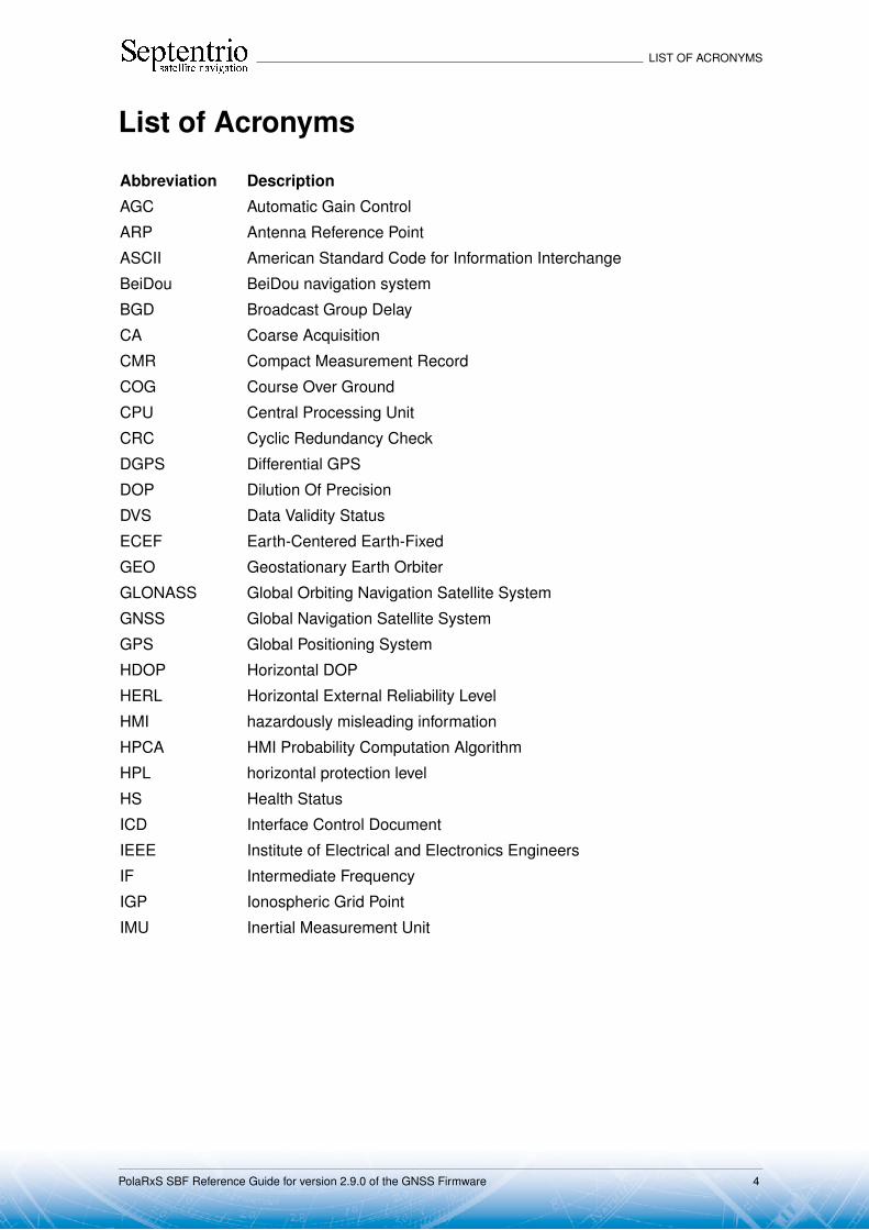
List of Acronyms
Abbreviation Description
AGC Automatic Gain Control
ARP Antenna Reference Point
ASCII American Standard Code for Information Interchange
BeiDou BeiDou navigation system
BGD Broadcast Group Delay
CA Coarse Acquisition
CMR Compact Measurement Record
COG Course Over Ground
CPU Central Processing Unit
CRC Cyclic Redundancy Check
DGPS Differential GPS
DOP Dilution Of Precision
DVS Data Validity Status
ECEF Earth-Centered Earth-Fixed
GEO Geostationary Earth Orbiter
GLONASS Global Orbiting Navigation Satellite System
GNSS Global Navigation Satellite System
GPS Global Positioning System
HDOP Horizontal DOP
HERL Horizontal External Reliability Level
HMI hazardously misleading information
HPCA HMI Probability Computation Algorithm
HPL horizontal protection level
HS Health Status
ICD Interface Control Document
IEEE Institute of Electrical and Electronics Engineers
IF Intermediate Frequency
IGP Ionospheric Grid Point
IMU Inertial Measurement Unit
PolaRxS SBF Reference Guide for version 2.9.0 of the GNSS Firmware 4

LIST OF ACRONYMS
INS Inertial Navigation System
IODC Issue of Data - Clock
IODE Issue Of Data Ephemeris
IP Internet Protocol
IRNSS Indian Regional Navigational Satellite System
ITRS International Terrestrial Reference System
LBand L-Band Receiver
L1 L1 carrier
L2 L2 carrier
L2C L2C code
LSB Least Significant Bit
MDB Minimum Detectable Bias
MSB Most Significant Bits
MT Message Type
NATO North Atlantic Treaty Organisation
NAV Navigation
NAVSTAR Navigation Satellite Timing And Ranging
NMEA National Marine Electronics Association
P P(Y) code
P1 P1 code
P2 P2 code
PDOP Position DOP
PLL Phase Locked Loop
PPP Precise Point Positioning
PPS Pulse Per Second
PRC Pseudorange Correction
PRN Pseudo Random Noise
PVT Position, Velocity and Time
QZSS Quasi-Zenith Satellite System
RAIM Receiver Autonomous Integrity Monitoring
RINEX Receiver Independent Exchange Format
RTCM Radio Technical Commission for Maritime Services
RTK Real-Time Kinematic
PolaRxS SBF Reference Guide for version 2.9.0 of the GNSS Firmware 5

1 Introduction
SBAS Space-Based Augmentation System
SBF Septentrio Binary Format
SF Single Frequency
SIS Signal In Space
SISA Signal in Space Accuracy
SNMP Simple Network Management Protocol
SV Space Vehicle
SVID Space Vehicle ID
TDOP Time DOP
TOW Time Of Week
UDRE User Differential Range Error
UERE User Equivalent Range Error
URA User Range Accuracy
USB Universal Serial Bus
UTC Coordinated Universal Time
VDOP Vertical DOP
VERL Vertical External Reliability Level
VPL vertical protection level
WGS84 World Geodetic System 1984
WN Week Number
WNc Week number
XERL External Reliability Levels
XOR Exclusive OR
XPL Horizontal or Vertical Protection Level
PolaRxS SBF Reference Guide for version 2.9.0 of the GNSS Firmware 6
1 Introduction
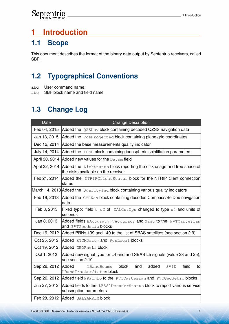
1 Introduction1.1 ScopeThis document describes the format of the binary data output by Septentrio receivers, calledSBF.
1.2 Typographical Conventionsabc User command name;abc SBF block name and field name.
1.3 Change Log
Date Change Description
Feb 04, 2015 Added the QZSNav block containing decoded QZSS navigation data
Jan 13, 2015 Added the PosProjected block containing plane grid coordinates
Dec 12, 2014 Added the base measurements quality indicator
July 14, 2014 Added the ISMR block containing ionospheric scintillation parameters
April 30, 2014 Added new values for the Datum field
April 22, 2014 Added the DiskStatus block reporting the disk usage and free space ofthe disks available on the receiver
Feb 21, 2014 Added the NTRIPClientStatus block for the NTRIP client connectionstatus
March 14, 2013 Added the QualityInd block containing various quality indicators
Feb 19, 2013 Added the CMPNav block containing decoded Compass/BeiDou navigationdata
Feb 8, 2013 Fixed typo: field t_oG of GALGstGps changed to type u4 and units ofseconds
Jan 8, 2013 Added fields HAccuracy, VAccuracy and Misc to the PVTCartesianand PVTGeodetic blocks
Dec 19, 2012 Added PRNs 139 and 140 to the list of SBAS satellites (see section 2.9)
Oct 25, 2012 Added RTCMDatum and PosLocal blocks
Oct 19, 2012 Added GEORawL5 block
Oct 1, 2012 Added new signal type for L-band and SBAS L5 signals (value 23 and 25),see section 2.10
Sep 29, 2012 Added LBandBeams block and added SVID field toLBandTrackerStatus block
Sep 20, 2012 Added field PPPInfo to the PVTCartesian and PVTGeodetic blocks
Jun 27, 2012 Added fields to the LBAS1DecoderStatus block to report various servicesubscription parameters
Feb 28, 2012 Added GALSARRLM block
PolaRxS SBF Reference Guide for version 2.9.0 of the GNSS Firmware 7

1 Introduction
Feb 6, 2012 Added QZSS signals and QZSRawL1CA, QZSRawL2C and QZSRawL5blocks
PolaRxS SBF Reference Guide for version 2.9.0 of the GNSS Firmware 8
2 SBF Outline
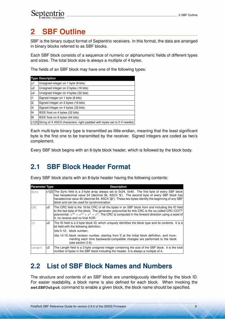
2 SBF OutlineSBF is the binary output format of Septentrio receivers. In this format, the data are arrangedin binary blocks referred to as SBF blocks.
Each SBF block consists of a sequence of numeric or alphanumeric fields of different typesand sizes. The total block size is always a multiple of 4 bytes.
The fields of an SBF block may have one of the following types:
Type Description
u1 Unsigned integer on 1 byte (8 bits)
u2 Unsigned integer on 2 bytes (16 bits)
u4 Unsigned integer on 4 bytes (32 bits)
i1 Signed integer on 1 byte (8 bits)
i2 Signed integer on 2 bytes (16 bits)
i4 Signed integer on 4 bytes (32 bits)
f4 IEEE float on 4 bytes (32 bits)
f8 IEEE float on 8 bytes (64 bits)
c1[X] String of X ASCII characters, right padded with bytes set to 0 if needed.
Each multi-byte binary type is transmitted as little-endian, meaning that the least significantbyte is the first one to be transmitted by the receiver. Signed integers are coded as two’scomplement.
Every SBF block begins with an 8-byte block header, which is followed by the block body.
2.1 SBF Block Header FormatEvery SBF block starts with an 8-byte header having the following contents:
Parameter Type Description
Sync c1[2] The Sync field is a 2-byte array always set to 0x24, 0x40. The first byte of every SBF blockhas hexadecimal value 24 (decimal 36, ASCII ’$’). The second byte of every SBF block hashexadecimal value 40 (decimal 64, ASCII ’@’). These two bytes identify the beginning of any SBFblock and can be used for synchronization.
CRC u2 The CRC field is the 16-bit CRC of all the bytes in an SBF block from and including the ID fieldto the last byte of the block. The generator polynomial for this CRC is the so-called CRC-CCITTpolynomial: x16 + x12 + x5 + x0. The CRC is computed in the forward direction using a seed of0, no reverse and no final XOR.
ID u2 The ID field is a 2-byte block ID, which uniquely identifies the block type and its contents. It is abit field with the following definition:bits 0-12: block number;bits 13-15: block revision number, starting from 0 at the initial block definition, and incre-
menting each time backwards-compatible changes are performed to the block(see section 2.6).
Length u2 The Length field is a 2-byte unsigned integer containing the size of the SBF block. It is the totalnumber of bytes in the SBF block including the header. It is always a multiple of 4.
2.2 List of SBF Block Names and NumbersThe structure and contents of an SBF block are unambiguously identified by the block ID.For easier readability, a block name is also defined for each block. When invoking thesetSBFOutput command to enable a given block, the block name should be specified.
PolaRxS SBF Reference Guide for version 2.9.0 of the GNSS Firmware 9
2 SBF Outline
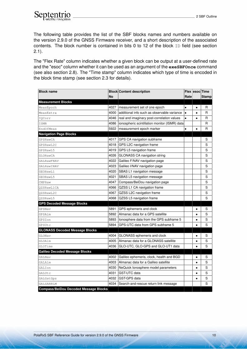
The following table provides the list of the SBF blocks names and numbers available onthe version 2.9.0 of the GNSS Firmware receiver, and a short description of the associatedcontents. The block number is contained in bits 0 to 12 of the block ID field (see section2.1).
The "Flex Rate" column indicates whether a given block can be output at a user-defined rateand the "esoc" column whether it can be used as an argument of the exeSBFOnce command(see also section 2.8). The "Time stamp" column indicates which type of time is encoded inthe block time stamp (see section 2.3 for details).
Block name Block Content description Flex esoc TimeNo Rate Stamp
Measurement Blocks
MeasEpoch 4027 measurement set of one epoch • • R
MeasExtra 4000 additional info such as observable variance • • R
IQCorr 4046 real and imaginary post-correlation values • • R
ISMR 4086 ionospheric scintillation monitor (ISMR) data R
EndOfMeas 5922 measurement epoch marker • • R
Navigation Page Blocks
GPSRawCA 4017 GPS CA navigation subframe S
GPSRawL2C 4018 GPS L2C navigation frame S
GPSRawL5 4019 GPS L5 navigation frame S
GLORawCA 4026 GLONASS CA navigation string S
GALRawFNAV 4022 Galileo F/NAV navigation page S
GALRawINAV 4023 Galileo I/NAV navigation page S
GEORawL1 4020 SBAS L1 navigation message S
GEORawL5 4021 SBAS L5 navigation message S
CMPRaw 4047 Compass/BeiDou navigation page S
QZSRawL1CA 4066 QZSS L1 CA navigation frame S
QZSRawL2C 4067 QZSS L2C navigation frame S
QZSRawL5 4068 QZSS L5 navigation frame S
GPS Decoded Message Blocks
GPSNav 5891 GPS ephemeris and clock • S
GPSAlm 5892 Almanac data for a GPS satellite • S
GPSIon 5893 Ionosphere data from the GPS subframe 5 • S
GPSUtc 5894 GPS-UTC data from GPS subframe 5 • S
GLONASS Decoded Message Blocks
GLONav 4004 GLONASS ephemeris and clock • S
GLOAlm 4005 Almanac data for a GLONASS satellite • S
GLOTime 4036 GLO-UTC, GLO-GPS and GLO-UT1 data • S
Galileo Decoded Message Blocks
GALNav 4002 Galileo ephemeris, clock, health and BGD • S
GALAlm 4003 Almanac data for a Galileo satellite • S
GALIon 4030 NeQuick Ionosphere model parameters • S
GALUtc 4031 GST-UTC data • S
GALGstGps 4032 GST-GPS data • S
GALSARRLM 4034 Search-and-rescue return link message S
Compass/BeiDou Decoded Message Blocks
PolaRxS SBF Reference Guide for version 2.9.0 of the GNSS Firmware 10

2 SBF Outline
Block name Block Content description Flex esoc TimeNo Rate Stamp
CMPNav 4081 Compass/BeiDou ephemeris and clock • S
QZSS Decoded Message Blocks
QZSNav 4095 QZSS ephemeris and clock • S
SBAS Decoded Message Blocks
GEOMT00 5925 MT00 : SBAS Don’t use for safety applications S
GEOPRNMask 5926 MT01 : PRN Mask assignments S
GEOFastCorr 5927 MT02-05/24: Fast Corrections S
GEOIntegrity 5928 MT06 : Integrity information S
GEOFastCorrDegr 5929 MT07 : Fast correction degradation factors S
GEONav 5896 MT09 : SBAS navigation message • S
GEODegrFactors 5930 MT10 : Degradation factors S
GEONetworkTime 5918 MT12 : SBAS Network Time/UTC offset parameters S
GEOAlm 5897 MT17 : SBAS satellite almanac • S
GEOIGPMask 5931 MT18 : Ionospheric grid point mask S
GEOLongTermCorr 5932 MT24/25 : Long term satellite error corrections S
GEOIonoDelay 5933 MT26 : Ionospheric delay corrections S
GEOServiceLevel 5917 MT27 : SBAS Service Message S
GEOClockEphCovMatrix 5934 MT28 : Clock-Ephemeris Covariance Matrix S
Position, Velocity and Time Blocks
PVTCartesian 4006 Position, velocity, and time in Cartesian coordinates • • R
PVTGeodetic 4007 Position, velocity, and time in geodetic coordinates • • R
PosCovCartesian 5905 Position covariance matrix (X,Y, Z) • • R
PosCovGeodetic 5906 Position covariance matrix (Lat, Lon, Alt) • • R
VelCovCartesian 5907 Velocity covariance matrix (X, Y, Z) • • R
VelCovGeodetic 5908 Velocity covariance matrix (North, East, Up) • • R
DOP 4001 Dilution of precision • • R
PosCart 4044 Position, variance and baseline in Cartesian coordinates • • R
PosLocal 4052 Position in a local datum • • R
PosProjected 4094 Plane grid coordinates • • R
PVTSatCartesian 4008 Satellite positions • • R
PVTResiduals 4009 Measurement residuals • • R
RAIMStatistics 4011 Integrity statistics • • R
GEOCorrections 5935 Orbit, Clock and pseudoranges SBAS corrections • • R
BaseVectorCart 4043 XYZ relative position and velocity with respect to base(s) • • R
BaseVectorGeod 4028 ENU relative position and velocity with respect to base(s) • • R
PVTSupport 4076 Reserved for maintenance and support • • R
EndOfPVT 5921 PVT epoch marker • • R
GNSS Attitude Blocks
AttEuler 5938 GNSS attitude expressed as Euler angles • • R
AttCovEuler 5939 Covariance matrix of attitude • • R
EndOfAtt 5943 GNSS attitude epoch marker • • R
Receiver Time Blocks
ReceiverTime 5914 Current receiver and UTC time • • R
xPPSOffset 5911 Offset of the xPPS pulse with respect to GNSS time R
External Event Blocks
PolaRxS SBF Reference Guide for version 2.9.0 of the GNSS Firmware 11

2 SBF Outline
Block name Block Content description Flex esoc TimeNo Rate Stamp
ExtEvent 5924 Time at the instant of an external event E
ExtEventPVTCartesian 4037 Cartesian position at the instant of an event E
ExtEventPVTGeodetic 4038 Geodetic position at the instant of an event E
Differential Correction Blocks
DiffCorrIn 5919 Incoming RTCM or CMR message R
BaseStation 5949 Base station coordinates R
RTCMDatum 4049 Datum information from the RTK service provider R
L-Band Demodulator Blocks
LBandTrackerStatus 4201 Status of the L-band signal tracking • R
LBAS1DecoderStatus 4202 Status of the LBAS1 L-band service R
LBAS1Messages 4203 LBAS1over-the-air message R
LBandBeams 4204 L-band satellite/beam information • R
Status Blocks
ChannelStatus 4013 Status of the tracking for all receiver channels • • R
ReceiverStatus 4014 Overall status information of the receiver • • R
SatVisibility 4012 Azimuth/elevation of visible satellites • • R
InputLink 4090 Statistics on input streams • • R
OutputLink 4091 Statistics on output streams • • R
NTRIPClientStatus 4053 NTRIP client connection status • R
IPStatus 4058 IP address, gateway and MAC address • R
QualityInd 4082 Quality indicators • R
DiskStatus 4059 Internal logging status • R
Miscellaneous Blocks
ReceiverSetup 5902 General information about the receiver set-up • R
Commands 4015 Commands entered by the user • R
Comment 5936 Comment entered by the user • R
BBSamples 4040 Baseband samples E
ASCIIIn 4075 Search-and-rescue return link message R
Deprecated or Obsolete Bocks
BaseLine 5950 R
2.3 SBF Block Time Stamp (TOW and WNc)Each SBF header is directly followed by a time stamp, which consists of two fields: TOW andWNc:
Parameter Type Units & Scale Do-Not-Use Description
Factor ValueTOW u4 0.001 s 4294967295 Time-Of-Week : Time-tag, expressed in whole
milliseconds from the beginning of the currentGPS week.
WNc u2 1 week 65535 The GPS week number associated with the TOW.WNc is a continuous week count (hence the "c").It is not affected by GPS week rollovers, whichoccur every 1024 weeks.By definition of the Galileo system time, WNc isalso the Galileo week number plus 1024.
In the SBF time stamps, the definition of the week always follows the GPS convention evenif the block contains data for another constellation. This means that WNc 0, TOW 0 corre-sponds to Jan 06,1980 at 00:00:00 UTC.
PolaRxS SBF Reference Guide for version 2.9.0 of the GNSS Firmware 12
2 SBF Outline
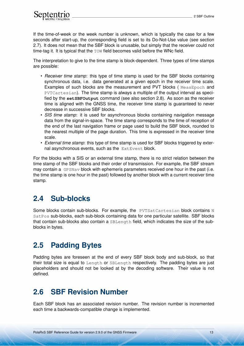
If the time-of-week or the week number is unknown, which is typically the case for a fewseconds after start-up, the corresponding field is set to its Do-Not-Use value (see section2.7). It does not mean that the SBF block is unusable, but simply that the receiver could nottime-tag it. It is typical that the TOW field becomes valid before the WNc field.
The interpretation to give to the time stamp is block-dependent. Three types of time stampsare possible:
• Receiver time stamp: this type of time stamp is used for the SBF blocks containingsynchronous data, i.e. data generated at a given epoch in the receiver time scale.Examples of such blocks are the measurement and PVT blocks ( MeasEpoch andPVTCartesian). The time stamp is always a multiple of the output interval as speci-fied by the setSBFOutput command (see also section 2.8). As soon as the receivertime is aligned with the GNSS time, the receiver time stamp is guaranteed to neverdecrease in successive SBF blocks.
• SIS time stamp: it is used for asynchronous blocks containing navigation messagedata from the signal-in-space. The time stamp corresponds to the time of reception ofthe end of the last navigation frame or page used to build the SBF block, rounded tothe nearest multiple of the page duration. This time is expressed in the receiver timescale.
• External time stamp: this type of time stamp is used for SBF blocks triggered by exter-nal asynchronous events, such as the ExtEvent block.
For the blocks with a SIS or an external time stamp, there is no strict relation between thetime stamp of the SBF blocks and their order of transmission. For example, the SBF streammay contain a GPSNav block with ephemeris parameters received one hour in the past (i.e.the time stamp is one hour in the past) followed by another block with a current receiver timestamp.
2.4 Sub-blocksSome blocks contain sub-blocks. For example, the PVTSatCartesian block contains NSatPos sub-blocks, each sub-block containing data for one particular satellite. SBF blocksthat contain sub-blocks also contain a SBLength field, which indicates the size of the sub-blocks in bytes.
2.5 Padding BytesPadding bytes are foreseen at the end of every SBF block body and sub-block, so thattheir total size is equal to Length or SBLength respectively. The padding bytes are justplaceholders and should not be looked at by the decoding software. Their value is notdefined.
2.6 SBF Revision NumberEach SBF block has an associated revision number. The revision number is incrementedeach time a backwards-compatible change is implemented.
PolaRxS SBF Reference Guide for version 2.9.0 of the GNSS Firmware 13

2 SBF Outline
As described in section 2.1, the block number is to be found in bits 0 to 12 of the ID field,and the revision is in bits 13 to 15 of that field.
A backwards-compatible change consists of adding one or more fields in the padding bytes,or in the fields marked as "reserved" in the block description. Such change should be unno-ticed by properly written decoding software that ignore the contents of padding and reservedfields (see also section 2.12). Each time such change happens, the revision number is in-cremented. The revision at which a given field has been introduced is documented in theblock description in chapter 3, unless that revision is 0 (see the ReceiverSetup block asan example). It is guaranteed that if a given field exists in revision N, it will also exist in allrevisions after N: no fields are withdrawn from SBF.
2.7 Do-Not-Use ValueIt might happen that one or more pieces of data in an SBF block are not known at block cre-ation time. For example, when there are insufficient satellite measurements to compute a po-sition solution, the position components found in the X, Y and Z fields of the PVTCartesianblock will not be available. To indicate that a given data item is not available or is currentlynot provided by the receiver, the corresponding field is set to a ’Do-Not-Use’ value that isnever reached in normal operation.
When applicable, the Do-Not-Use value is mentioned in the block description. The Do-Not-Use value refers to the raw contents of the field, without applying the scale factor. A field setto its Do-Not-Use value should always be discarded by the decoding software.
2.8 Output RateIn general, the default output rate for each SBF block is the renewal rate of the information.For instance, the GPSNav block is output each time a new ephemeris data set is receivedfrom a given GPS satellite. The default output rates of GNSS measurement blocks, PVTblocks and integrated INS/GNSS blocks depend on your permission set. These three ratescan be checked by the command getReceiverCapabilities.
The default output rate is specified for each block in chapter 3. To instruct the receiverto output a given block at its default rate, the "OnChange" rate has to be specified in thesetSBFOutput command. Note that the maximum rate actually available on your receivermay be lower than the one specified in chapter 3, depending on your permission set.
Some blocks can only be output at their default rate (e.g. the GPSNav block). Others can bedecimated to a user-selectable rate (which is by nature lower than the default rate). A subsetof blocks can also be output "once" using the exeSBFOnce command. This can be handyto get a one-shot overview of a particular receiver state. Whether a given block supports auser-selectable rate and whether it belongs to the "output once" set is indicated in the SBFblock list in section 2.2.
Attempting to force another rate than the default one for those blocks that do not support auser-selectable rate has no effect.
PolaRxS SBF Reference Guide for version 2.9.0 of the GNSS Firmware 14

2 SBF Outline
2.9 Space Vehicle ID and GLONASS FrequencyNumber
Satellites are identified by the SVID (or PRN) and FreqNr fields, defined as follows:
Field Type Do-Not-Use Description RINEX satellite code
ValueSVID or PRN u1 0 Satellite ID: The following ranges are defined:
1-37: PRN number of a GPS satellite Gnn (nn = SVID)
38-61: Slot number of a GLONASS satellite withan offset of 37
Rnn (nn = SVID-37)
62: GLONASS satellite of which the slot numberis not known
NA
71-102: PRN number of a GALILEO satellite withan offset of 70
Enn (nn = SVID-70)
107-119: L-Band (MSS) satellite. Correspondingsatellite name can be found in the LBandBeamsblock.
NA
120-140: PRN number of an SBAS satellite Snn (nn = SVID-100)
141-172: PRN number of a Compass/BeiDousatellite with an offset of 140
Cnn (nn = SVID-140)
181-187: PRN number of a QZSS satellite withan offset of 180
Jnn (nn = SVID-180)
191-197: PRN number of an IRNSS satellite withan offset of 190
Inn (nn = SVID-190)
FreqNr u1 0 GLONASS frequency number, with an offset of8. It ranges from 1 (corresponding to an actualfrequency number of -7) to 21 (corresponding toan actual frequency number of 13).
For non-GLONASS satellites, FreqNr is re-served and must be ignored by the decodingsoftware.
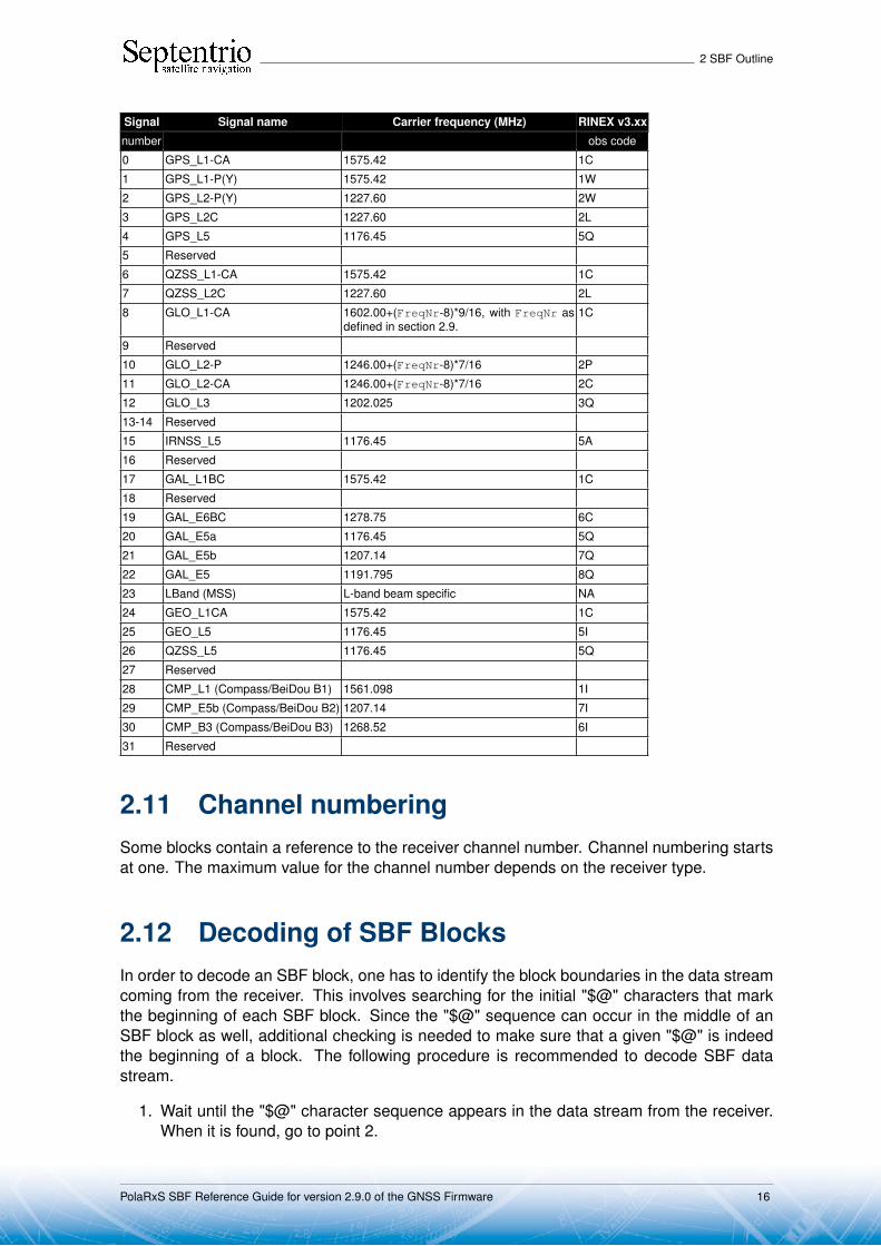
2.10 Signal TypeSome sub-blocks contain a signal type field, which identify the type of signal and modulationthe sub-blocks applies to. The signal numbering is defined as follows:
PolaRxS SBF Reference Guide for version 2.9.0 of the GNSS Firmware 15
2 SBF Outline
Signal Signal name Carrier frequency (MHz) RINEX v3.xx
number obs code
0 GPS_L1-CA 1575.42 1C
1 GPS_L1-P(Y) 1575.42 1W
2 GPS_L2-P(Y) 1227.60 2W
3 GPS_L2C 1227.60 2L
4 GPS_L5 1176.45 5Q
5 Reserved
6 QZSS_L1-CA 1575.42 1C
7 QZSS_L2C 1227.60 2L
8 GLO_L1-CA 1602.00+(FreqNr-8)*9/16, with FreqNr asdefined in section 2.9.
1C
9 Reserved
10 GLO_L2-P 1246.00+(FreqNr-8)*7/16 2P
11 GLO_L2-CA 1246.00+(FreqNr-8)*7/16 2C
12 GLO_L3 1202.025 3Q
13-14 Reserved
15 IRNSS_L5 1176.45 5A
16 Reserved
17 GAL_L1BC 1575.42 1C
18 Reserved
19 GAL_E6BC 1278.75 6C
20 GAL_E5a 1176.45 5Q
21 GAL_E5b 1207.14 7Q
22 GAL_E5 1191.795 8Q
23 LBand (MSS) L-band beam specific NA
24 GEO_L1CA 1575.42 1C
25 GEO_L5 1176.45 5I
26 QZSS_L5 1176.45 5Q
27 Reserved
28 CMP_L1 (Compass/BeiDou B1) 1561.098 1I
29 CMP_E5b (Compass/BeiDou B2) 1207.14 7I
30 CMP_B3 (Compass/BeiDou B3) 1268.52 6I
31 Reserved
2.11 Channel numberingSome blocks contain a reference to the receiver channel number. Channel numbering startsat one. The maximum value for the channel number depends on the receiver type.
2.12 Decoding of SBF BlocksIn order to decode an SBF block, one has to identify the block boundaries in the data streamcoming from the receiver. This involves searching for the initial "$@" characters that markthe beginning of each SBF block. Since the "$@" sequence can occur in the middle of anSBF block as well, additional checking is needed to make sure that a given "$@" is indeedthe beginning of a block. The following procedure is recommended to decode SBF datastream.
1. Wait until the "$@" character sequence appears in the data stream from the receiver.When it is found, go to point 2.
PolaRxS SBF Reference Guide for version 2.9.0 of the GNSS Firmware 16
2 SBF Outline
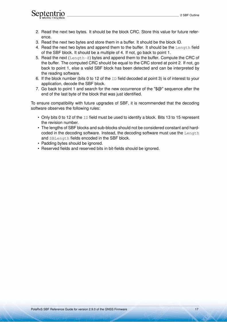
2. Read the next two bytes. It should be the block CRC. Store this value for future refer-ence.
3. Read the next two bytes and store them in a buffer. It should be the block ID.4. Read the next two bytes and append them to the buffer. It should be the Length field
of the SBF block. It should be a multiple of 4. If not, go back to point 1.5. Read the next (Length-8) bytes and append them to the buffer. Compute the CRC of
the buffer. The computed CRC should be equal to the CRC stored at point 2. If not, goback to point 1, else a valid SBF block has been detected and can be interpreted bythe reading software.
6. If the block number (bits 0 to 12 of the ID field decoded at point 3) is of interest to yourapplication, decode the SBF block.
7. Go back to point 1 and search for the new occurrence of the "$@" sequence after theend of the last byte of the block that was just identified.
To ensure compatibility with future upgrades of SBF, it is recommended that the decodingsoftware observes the following rules:
• Only bits 0 to 12 of the ID field must be used to identify a block. Bits 13 to 15 representthe revision number.
• The lengths of SBF blocks and sub-blocks should not be considered constant and hard-coded in the decoding software. Instead, the decoding software must use the Lengthand SBLength fields encoded in the SBF block.
• Padding bytes should be ignored.• Reserved fields and reserved bits in bit-fields should be ignored.
PolaRxS SBF Reference Guide for version 2.9.0 of the GNSS Firmware 17

3 SBF Block Definitions
3 SBF Block Definitions3.1 Measurement BlocksMeasEpoch Number: 4027
"OnChange" interval: 10 ms
This block contains all the GNSS measurements (observables) taken at the time given bythe TOW and WNc fields.
For each tracked signal, the following measurement set is available:
• the pseudorange• the carrier phase• the Doppler• the C/N0• the lock-time.
To decrease the block size, all the measurements from a given satellite are referenced toone master measurement set. For instance, the L2 pseudorange (C2) is not much differentfrom the L1 pseudorange (C1), such that the difference between C2 and C1 is encoded,instead of the absolute value of C2.
This is done by using a two-level sub-block structure. All the measurements from agiven satellite are stored in a MeasEpochChannelType1 sub-block. The first part of thissub-block contains the master measurements, encoded as absolute values. The secondpart contains slave measurements, for which only the delta values are encoded in smallerMeasEpochChannelType2 sub-blocks.
Every MeasEpochChannelType1 sub-block contains a field "N2", which gives thenumber of nested MeasEpochChannelType2 sub-blocks. If there is only one signaltracked for a given satellite, there are no slave measurements and N2 is set to 0.
Decoding is done as follows:
1. Decode the master measurements and the N2 value from theMeasEpochChannelType1 sub-block.
2. If N2 is not 0, decode the N2 nested MeasEpochChannelType2 sub-blocks.3. Go back to 1 till the N1 MeasEpochChannelType1 sub-blocks have been decoded.
PolaRxS SBF Reference Guide for version 2.9.0 of the GNSS Firmware 18
3 SBF Block Definitions
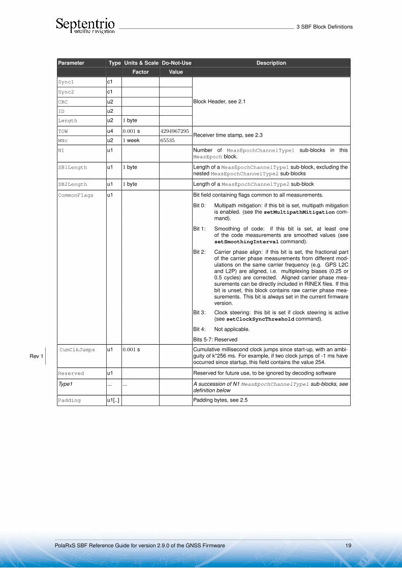
Parameter Type Units & Scale Do-Not-Use Description
Factor Value
Sync1 c1
Block Header, see 2.1
Sync2 c1
CRC u2
ID u2
Length u2 1 byte
TOW u4 0.001 s 4294967295Receiver time stamp, see 2.3
WNc u2 1 week 65535
N1 u1 Number of MeasEpochChannelType1 sub-blocks in thisMeasEpoch block.
SB1Length u1 1 byte Length of a MeasEpochChannelType1 sub-block, excluding thenested MeasEpochChannelType2 sub-blocks
SB2Length u1 1 byte Length of a MeasEpochChannelType2 sub-block
CommonFlags u1 Bit field containing flags common to all measurements.
Bit 0: Multipath mitigation: if this bit is set, multipath mitigationis enabled. (see the setMultipathMitigation com-mand).
Bit 1: Smoothing of code: if this bit is set, at least oneof the code measurements are smoothed values (seesetSmoothingInterval command).
Bit 2: Carrier phase align: if this bit is set, the fractional partof the carrier phase measurements from different mod-ulations on the same carrier frequency (e.g. GPS L2Cand L2P) are aligned, i.e. multiplexing biases (0.25 or0.5 cycles) are corrected. Aligned carrier phase mea-surements can be directly included in RINEX files. If thisbit is unset, this block contains raw carrier phase mea-surements. This bit is always set in the current firmwareversion.
Bit 3: Clock steering: this bit is set if clock steering is active(see setClockSyncThreshold command).
Bit 4: Not applicable.
Bits 5-7: Reserved
CumClkJumps u1 0.001 s Cumulative millisecond clock jumps since start-up, with an ambi-guity of k*256 ms. For example, if two clock jumps of -1 ms haveoccurred since startup, this field contains the value 254.
Rev 1
Reserved u1 Reserved for future use, to be ignored by decoding software
Type1 ... ... A succession of N1 MeasEpochChannelType1 sub-blocks, seedefinition below
Padding u1[..] Padding bytes, see 2.5
PolaRxS SBF Reference Guide for version 2.9.0 of the GNSS Firmware 19

3 SBF Block Definitions
MeasEpochChannelType1 sub-block definition:
Parameter Type Units & Scale Do-Not-Use Description
Factor Value
RxChannel u1 Receiver channel on which this satellite is currently tracked (see2.11).
Type u1 Bit field indicating the signal type and antenna ID:
Bits 0-4: signal number, see 2.10.
Bits 5-7: Antenna ID: 0 for main, 1 for Aux1 and 2 for Aux2
SVID u1 Satellite ID, see 2.9
Misc u1 Bit field containing the MSB of the pseudorange.
4294967.296 m 0 (1) Bits 0-3: CodeMSB: MSB of the pseudorange (this is an unsignedvalue).
Bits 4-7: Reserved
CodeLSB u4 0.001 m 0 (1) LSB of the pseudorange. The pseudorange expressed in metersis computed as follows:PRtype1[m] = (CodeMSB*4294967296+CodeLSB)*0.001
where CodeMSB is part of the Misc field.
Doppler i4 0.0001 Hz −2147483648 Carrier Doppler (positive for approaching satellites).To compute the Doppler in Hz, use:Dtype1[Hz] = Doppler*0.0001
CarrierLSB u2 0.001 cycles 0 (2) LSB of the carrier phase relative to the pseudorange
CarrierMSB i1 65.536 cycles −128 (2) MSB of the carrier phase relative to the pseudorange. The fullcarrier phase can be computed by:L[cycles] = PRtype1[m]/λ
+(CarrierMSB*65536+CarrierLSB)*0.001
where λ is the carrier wavelength corresponding to the frequencyof the signal type in the Type field above: λ=299792458/fL m,with fL the carrier frequency as listed in section 2.10.
CN0 u1 0.25 dB-Hz 255 The C/N0 in dB-Hz is computed as follows, depending on thesignal type in the Type field:C/N0[dB-Hz] = CN0*0.25 if the signal number is 1 or 2C/N0[dB-Hz] = CN0*0.25+10 otherwise
LockTime u2 1 s 65535 Duration of continuous carrier phase. The lock-time is reset atthe initial lock of the phase-locked-loop, and whenever a loss oflock condition occurs.
If the lock-time is longer than 65534s, it is clipped to 65534s.
If the carrier phase measurement is not available, this fieldis set to its Do-Not-Use value.
ObsInfo u1 Bit field:
Bit 0: if set, the pseudorange measurement is smoothed
Bit 1: if set, the smoothing filter has reached the requestedsmoothing interval
Bit 2: this bit is set when the carrier phase (L) has a half-cycleambiguity
0 Bits 3-7: FreqNr: for GLONASS satellites, these bits contain thefrequency number with an offset of 8 (see 2.9), otherwisethey are reserved and must be ignored by the decodingsoftware.
N2 u1 Number of MeasEpochChannelType2 sub-blocks contained inthis MeasEpochChannelType1 sub-block.
(1) The pseudorange is invalid if both CodeMSB is 0 and CodeLSB is 0.(2) The carrier phase is invalid if both CarrierMSB is -128 and CarrierLSB is 0.
PolaRxS SBF Reference Guide for version 2.9.0 of the GNSS Firmware 20

3 SBF Block Definitions
Padding u1[..] Padding bytes, see 2.5
Type2 ... ... A succession of N2 MeasEpochChannelType2 sub-blocks, seedefinition below
MeasEpochChannelType2 sub-block definition:
Parameter Type Units & Scale Do-Not-Use Description
Factor Value
Type u1 Bit field indicating the signal type and antenna ID:
Bits 0-4: signal number, see 2.10.
Bits 5-7: Antenna ID: 0 for main, 1 for Aux1 and 2 for Aux2
LockTime u1 1 s 255 See corresponding field in the MeasEpochChannelType1 sub-block above, except that the value is clipped to 254 instead of65534.
CN0 u1 0.25 dB-Hz 255 See corresponding field in the MeasEpochChannelType1 sub-block above.
OffsetsMSB u1 Bit field containing the MSB of the code and of the Doppler off-sets with respect to the MeasEpochChannelType1 sub-block.
65.536 m −4 (3) Bits 0-2: CodeOffsetMSB: MSB of the code offset.
6.5536 Hz −16 (4) Bits 3-7: DopplerOffsetMSB: MSB of the Doppler offset.
CodeOffsetMSB and DopplerOffsetMSB are coded as two’scomplement.Refer to the CodeOffsetLSB and DopplerOffsetLSB fieldsto see how to use this field.
CarrierMSB i1 65.536 cycles −128 (5) MSB of the carrier phase relative to the pseudorange.
ObsInfo u1 Bit field:
Bit 0: if set, the pseudorange measurement is smoothed
Bit 1: if set, the smoothing filter has reached the requestedsmoothing interval
Bit 2: this bit is set when the carrier phase (L) has a half-cycleambiguity
Bits 3-7: Reserved
CodeOffsetLSB u2 0.001 m 0 (3) LSB of the code offset with respect to pseudorange in theMeasEpochChannelType1 sub-block. To compute the pseu-dorange, use:PRtype2 [m] = PRtype1[m]
+ (CodeOffsetMSB*65536+CodeOffsetLSB)*0.001
CarrierLSB u2 0.001 cycles 0 (5) LSB of the carrier phase relative to the pseudorange. The fullcarrier phase can be computed by:L[cycles]= PRtype2[m]/λ
+(CarrierMSB*65536+CarrierLSB)*0.001
where λ is the carrier wavelength corresponding to the sig-nal type in the Type field.
(3) The pseudorange is invalid if both CodeOffsetMSB is -4 and CodeOffsetLSB is 0.(4) The Doppler is invalid if both DopplerOffsetMSB is -16 and DopplerOffsetLSB is 0.(5) The carrier phase is invalid if both CarrierMSB is -128 and CarrierLSB is 0.
PolaRxS SBF Reference Guide for version 2.9.0 of the GNSS Firmware 21

3 SBF Block Definitions
DopplerOffsetLSB u2 0.0001 Hz 0 (4) LSB of the Doppler offset relative to the Doppler in theMeasEpochChannelType1 sub-block. To compute theDoppler, use:Dtype2[Hz] = Dtype1[Hz]*α
+(DopplerOffsetMSB*65536+DopplerOffsetLSB)*1e-4,
where α is the ratio of the carrier frequency correspondingto the observable type in this MeasEpochChannelType2sub-block, and that of the master observable type in the parentMeasEpochChannelType1 sub-block (see section 2.10 for alist of all carrier frequencies).
Padding u1[..] Padding bytes, see 2.5
PolaRxS SBF Reference Guide for version 2.9.0 of the GNSS Firmware 22

3 SBF Block Definitions
MeasExtra Number: 4000"OnChange" interval: 10 ms
This block contains extra information associated with the measurements contained in theMeasEpoch block, such as the internal corrections parameters applied during the measure-ment pre-processing, and the noise variances.
Parameter Type Units & Scale Do-Not-Use Description
Factor Value
Sync1 c1
Block Header, see 2.1
Sync2 c1
CRC u2
ID u2
Length u2 1 byte
TOW u4 0.001 s 4294967295Receiver time stamp, see 2.3
WNc u2 1 week 65535
N u1 Number of sub-blocks in this MeasExtra block.
SBLength u1 1 byte Length of a sub-block
DopplerVarFactor f4 1 Hz2 / cycle2 Factor to be used to compute the Doppler variance from thecarrier phase variance. More specifically, the Doppler variancein mHz2 can be computed by:σ2Doppler[mHz2] = CarrierVariance * DopplerVarFactor,
Where CarrierVariance can be found for each measurementtype in the MeasExtraChannelSub sub-blocks.
ChannelSub ... ... A succession of N MeasExtraChannelSub sub-blocks, seedefinition below
Padding u1[..] Padding bytes, see 2.5
MeasExtraChannelSub sub-block definition:
Parameter Type Units & Scale Do-Not-Use Description
Factor Value
RxChannel u1 Receiver channel on which this satellite is currently tracked (see2.11).
Type u1 Bit field indicating the signal type and antenna ID:
Bits 0-4: signal number, see 2.10.
Bits 5-7: Antenna ID: 0 for main, 1 for Aux1 and 2 for Aux2
MPCorrection i2 0.001 m Multipath correction applied to the pseudorange. This number hasto be added to the pseudorange to recover the raw pseudorangeas it would be if multipath mitigation was not used.
SmoothingCorr i2 0.001 m Smoothing correction applied to the pseudorange. This numberhas to be added to the pseudorange to recover the raw pseudor-ange as it would be if smoothing was disabled.
CodeVar u2 0.0001 m2 65535 Estimated code tracking noise variance.If the variance is larger than 65534 cm2, it is clipped to 65534cm2.
CarrierVar u2 1 mcycle2 65535 Estimated carrier tracking noise variance. This value can bemultiplied by DopplerVarFactor to compute the Dopplermeasurement variance.
If the variance is larger than 65534 mcycles2, it is clippedto 65534 mcycles2.
PolaRxS SBF Reference Guide for version 2.9.0 of the GNSS Firmware 23

3 SBF Block Definitions
LockTime u2 1 s 65535 Duration of continuous carrier phase. The lock-time is reset atthe initial lock after a signal (re)acquisition.
If the lock-time is longer than 65534s, it is clipped to 65534s.
If the carrier phase measurement is not available, this fieldis set to its Do-Not-Use value.
CumLossCont u1 Carrier phase cumulative loss-of-continuity counter for the signaltype, antenna and satellite this sub-block refers to. This counterstarts at zero at receiver start-up, and is incremented at each ini-tial lock after signal (re)acquisition, or when a cycle slip is de-tected.
Reserved u1 Reserved.
Rev 1
Info u1 Bit field:
Bits 0-3: Reserved
Bits 4-7: Reserved.
Rev 2
Padding u1[..] Padding bytes, see 2.5
PolaRxS SBF Reference Guide for version 2.9.0 of the GNSS Firmware 24

3 SBF Block Definitions
IQCorr Number: 4046
"OnChange" interval: 10 ms
This block contains punctual correlation values (real and imaginary parts) and carrierphase measurements (modulo 65.536 cycles) for all signal types except for GPS L2P andGLONASS L2P.
It is typical to output the IQCorr block at a 50-Hz or 100-Hz rate and the MeasEpoch blockat 1-Hz or 10-Hz. The carrier phase measurement from the low-rate MeasEpoch block canbe used to resolve the 65.536-cycle ambiguity of the carrier phase in the IQCorr block.
Note that high-rate output is only possible on USB or Ethernet connections. COMports typically do not offer enough bandwidth to support 50-Hz IQCorr output.
Note that this feature may not be enabled on your receiver. It is under permissioncontrol.
Parameter Type Units & Scale Do-Not-Use Description
Factor Value
Sync1 c1
Block Header, see 2.1
Sync2 c1
CRC u2
ID u2
Length u2 1 byte
TOW u4 0.001 s 4294967295Receiver time stamp, see 2.3
WNc u2 1 week 65535
N u1 Number of sub-blocks in this IQCorr block.
SBLength u1 1 byte Length of a sub-block
CorrDuration u1 0.001 s Duration over which the correlations are computed (coherent in-tegration time, except for SBAS L1 where a non-coherent integra-tion is used).
CumClkJumps u1 0.001 s Cumulative millisecond clock jumps since start-up, with an ambi-guity of k*256 ms. For example, if two clock jumps of -1 ms haveoccurred since startup, this field contains the value 254.
Rev 1
Reserved u1[2] Reserved for future use.
ChannelSub ... ... A succession of N IQCorrChannelSub sub-blocks, see defini-tion below
Padding u1[..] Padding bytes, see 2.5
PolaRxS SBF Reference Guide for version 2.9.0 of the GNSS Firmware 25

3 SBF Block Definitions
IQCorrChannelSub sub-block definition:
Parameter Type Units & Scale Do-Not-Use Description
Factor Value
RxChannel u1 Receiver channel on which this satellite is currently tracked (see2.11).
Type u1 Bit field indicating the signal type and antenna ID:
Bits 0-5: signal number, see 2.10.
Bits 6-7: Antenna ID: 0 for main, 1 for Aux1 and 2 for Aux2
SVID u1 Satellite ID, see 2.9
CorrIQ_MSB u1 136 (6) Bit field containing the MSB of the correlation values:
Bits 0-3: I_MSB: MSB of the I correlation value, two’s comple-ment. See CorrI_LSB for usage.
Bits 4-7: Q_MSB: MSB of the Q correlation value, two’s comple-ment. See CorrQ_LSB for usage.
CorrI_LSB u1 0 (6) LSB of the real component of the punctual correlation value,unsigned. The full I correlation value is computed by:
I = I_MSB*256+CorrI_LSB
CorrQ_LSB u1 0 (6) LSB of the imaginary component of the punctual correlationvalue, unsigned. The full Q correlation value is computed by:
Q = Q_MSB*256+CorrQ_LSB
CarrierPhaseLSB u2 0.001 cycles 16-bit LSB of the carrier phase measurement, expressed in 0.001cycles.Rev 1
Padding u1[..] Padding bytes, see 2.5
(6) The correlation values must be ignored if CorrIQ_MSB is set to 136 and CorrI_LSB is set to 0 andCorrQ_LSB is set to 0 (all conditions met together).
PolaRxS SBF Reference Guide for version 2.9.0 of the GNSS Firmware 26

3 SBF Block Definitions
ISMR Number: 4086"OnChange" interval: 60s
This block reports the S4 and the so-called "sigma phase" ionosphere scintillation parame-ters for all tracked satellites and signals. This block is output every minute on the minute.
S4 is the standard deviation of 50-Hz raw signal power samples normalized to the av-erage signal power over an interval of 60 seconds.
Sigma phase is the standard deviation, in radians, of 50-Hz detrended carrier phasesamples averaged over an interval of 60 seconds. It is also referred to as "Phi60". Thedetrending is performed by filtering the raw carrier phase measurements by a high-passsixth order Butterworth filter having a cutoff frequency of 0.1Hz.
Note that this feature may not be enabled on your receiver. It is under permissioncontrol.
Parameter Type Units & Scale Do-Not-Use Description
Factor Value
Sync1 c1
Block Header, see 2.1
Sync2 c1
CRC u2
ID u2
Length u2 1 byte
TOW u4 0.001 s 4294967295Receiver time stamp, see 2.3
WNc u2 1 week 65535
N u1 Number of sub-blocks in this ISMR block.
SBLength u1 1 byte Length of a sub-block
Reserved u1[4] Reserved for future use.
ISMRChannel ... ... A succession of N ISMRChannel sub-blocks, see definition be-low
Padding u1[..] Padding bytes, see 2.5
ISMRChannel sub-block definition:
Parameter Type Units & Scale Do-Not-Use Description
Factor Value
RXChannel u1 Receiver channel on which this satellite is currently tracked (see2.11).
Type u1 Signal type:
Bits 0-5: signal number, see 2.10.
Bits 6-7: Reserved
SVID u1 Satellite ID, see 2.9
Reserved u1 Reserved for future use.
S4 u2 0.001 65535 Amplitude scintillation index
SigmaPhi u2 0.001 rad 65535 Phase scintillation index
Padding u1[..] Padding bytes, see 2.5
PolaRxS SBF Reference Guide for version 2.9.0 of the GNSS Firmware 27

3 SBF Block Definitions
EndOfMeas Number: 5922"OnChange" interval: 10 ms
This block marks the end of the transmission of all measurement-related blocks belonging toa given epoch.
Parameter Type Units & Scale Do-Not-Use Description
Factor Value
Sync1 c1
Block Header, see 2.1
Sync2 c1
CRC u2
ID u2
Length u2 1 byte
TOW u4 0.001 s 4294967295Receiver time stamp, see 2.3
WNc u2 1 week 65535
Padding u1[..] Padding bytes, see 2.5
PolaRxS SBF Reference Guide for version 2.9.0 of the GNSS Firmware 28

3 SBF Block Definitions
3.2 Navigation Page Blocks
GPSRawCA Number: 4017"OnChange" interval: 6s
This block contains the 300 bits of a GPS C/A subframe. It is generated each time a newsubframe is received, i.e. every 6 seconds.
Parameter Type Units & Scale Do-Not-Use Description
Factor Value
Sync1 c1
Block Header, see 2.1
Sync2 c1
CRC u2
ID u2
Length u2 1 byte
TOW u4 0.001 s 4294967295SIS time stamp, see 2.3
WNc u2 1 week 65535
SVID u1 Satellite ID, see 2.9
CRCPassed u1 Status of the CRC or parity check:0: CRC or parity check failed1: CRC or parity check passed
ViterbiCnt u1 Not applicable
Source u1 Bit field:
Bits 0-4: Signal type from which the bits have been received, asdefined in 2.10
Bits 5-7: Reserved
FreqNr u1 Not applicable
Reserved u1 Reserved for future use, to be ignored by decoding software.
NAVBits u4[10] NAVBits contains the 300 bits of a GPS C/A subframe.
Encoding: For easier parsing, the bits are stored as a suc-cession of 10 32-bit words. Since the actual words in thesubframe are 30-bit long, two unused bits are inserted in each32-bit word. More specifically, each 32-bit word has the followingformat:
Bits 0-5: 6 parity bits (referred to as D25 to D30 in the GPSICD), XOR-ed with the last transmitted bit of the previ-ous word (D∗
30)).
Bits 6-29: source data bits (referred to as dn in the GPS ICD).The first received bit is the MSB.
Bits 30-31: Reserved
Padding u1[..] Padding bytes, see 2.5
PolaRxS SBF Reference Guide for version 2.9.0 of the GNSS Firmware 29

3 SBF Block Definitions
GPSRawL2C Number: 4018"OnChange" interval: 12s
This block contains the 300 bits of a GPS L2C CNAV subframe (the so-called Dc(t) datastream).
Parameter Type Units & Scale Do-Not-Use Description
Factor Value
Sync1 c1
Block Header, see 2.1
Sync2 c1
CRC u2
ID u2
Length u2 1 byte
TOW u4 0.001 s 4294967295SIS time stamp, see 2.3
WNc u2 1 week 65535
SVID u1 Satellite ID, see 2.9
CRCPassed u1 Status of the CRC or parity check:0: CRC or parity check failed1: CRC or parity check passed
ViterbiCnt u1 Viterbi decoder error count over the subframe
Source u1 Bit field:
Bits 0-4: Signal type from which the bits have been received, asdefined in 2.10
Bits 5-7: Reserved
FreqNr u1 Not applicable
Reserved u1 Reserved for future use, to be ignored by decoding software.
NAVBits u4[10] NAVBits contains the 300 bits of a GPS CNAV subframe.
Encoding: NAVBits contains all the bits of the frame, in-cluding the preamble. The first received bit is stored as theMSB of NAVBits[0]. The unused bits in NAVBits[9] must beignored by the decoding software.
Padding u1[..] Padding bytes, see 2.5
PolaRxS SBF Reference Guide for version 2.9.0 of the GNSS Firmware 30
3 SBF Block Definitions
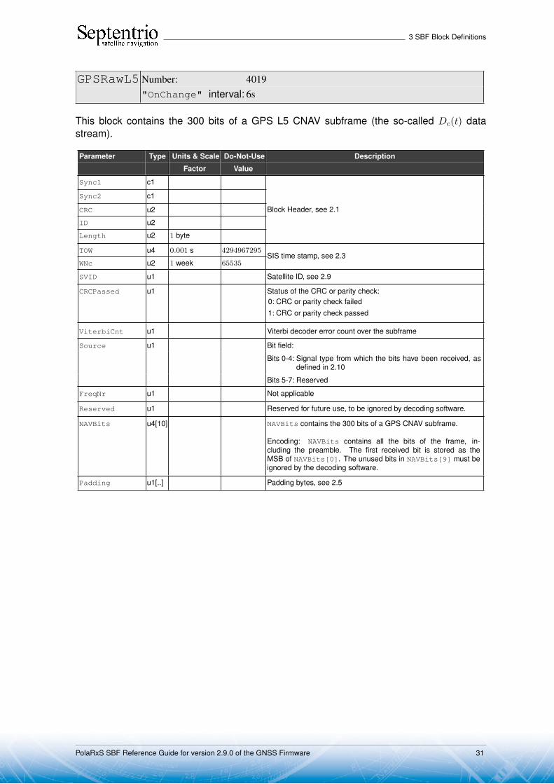
GPSRawL5 Number: 4019"OnChange" interval: 6s
This block contains the 300 bits of a GPS L5 CNAV subframe (the so-called Dc(t) datastream).
Parameter Type Units & Scale Do-Not-Use Description
Factor Value
Sync1 c1
Block Header, see 2.1
Sync2 c1
CRC u2
ID u2
Length u2 1 byte
TOW u4 0.001 s 4294967295SIS time stamp, see 2.3
WNc u2 1 week 65535
SVID u1 Satellite ID, see 2.9
CRCPassed u1 Status of the CRC or parity check:0: CRC or parity check failed1: CRC or parity check passed
ViterbiCnt u1 Viterbi decoder error count over the subframe
Source u1 Bit field:
Bits 0-4: Signal type from which the bits have been received, asdefined in 2.10
Bits 5-7: Reserved
FreqNr u1 Not applicable
Reserved u1 Reserved for future use, to be ignored by decoding software.
NAVBits u4[10] NAVBits contains the 300 bits of a GPS CNAV subframe.
Encoding: NAVBits contains all the bits of the frame, in-cluding the preamble. The first received bit is stored as theMSB of NAVBits[0]. The unused bits in NAVBits[9] must beignored by the decoding software.
Padding u1[..] Padding bytes, see 2.5
PolaRxS SBF Reference Guide for version 2.9.0 of the GNSS Firmware 31

3 SBF Block Definitions
GLORawCA Number: 4026"OnChange" interval: 2s
This block contains the 85 bits of a GLONASS L1CA or L2CA navigation string.
Parameter Type Units & Scale Do-Not-Use Description
Factor Value
Sync1 c1
Block Header, see 2.1
Sync2 c1
CRC u2
ID u2
Length u2 1 byte
TOW u4 0.001 s 4294967295SIS time stamp, see 2.3
WNc u2 1 week 65535
SVID u1 Satellite ID, see 2.9
CRCPassed u1 Status of the CRC or parity check:0: CRC or parity check failed1: CRC or parity check passed
ViterbiCnt u1 Not applicable
Source u1 Bit field:
Bits 0-4: Signal type from which the bits have been received, asdefined in 2.10
Bits 5-7: Reserved
FreqNr u1 Frequency number, with an offset of 8. See 2.9
Reserved u1 Reserved for future use, to be ignored by decoding software.
NAVBits u4[3] NAVBits contains the first 85 bits of a GLONASS C/A string (i.e.all bits of the string with the exception of the time mark).
Encoding: The first received bit is stored as the MSB ofNAVBits[0]. The unused bits in NAVBits[2] must be ignoredby the decoding software.
Padding u1[..] Padding bytes, see 2.5
PolaRxS SBF Reference Guide for version 2.9.0 of the GNSS Firmware 32
3 SBF Block Definitions
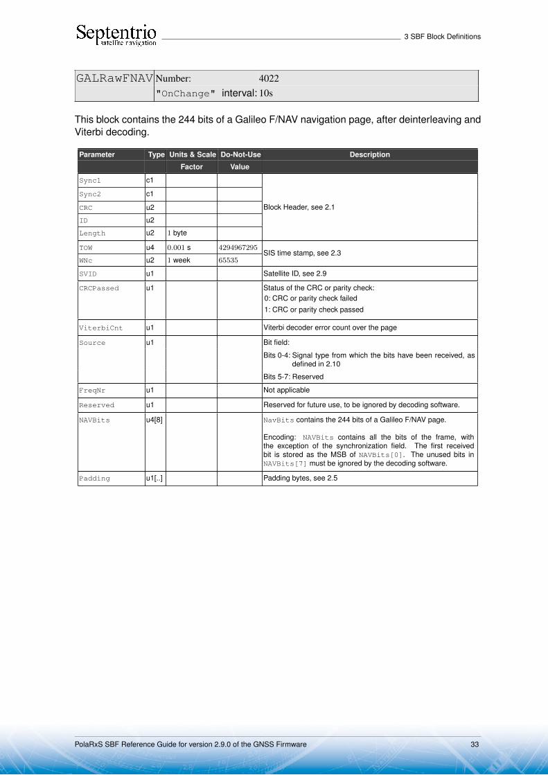
GALRawFNAV Number: 4022"OnChange" interval: 10s
This block contains the 244 bits of a Galileo F/NAV navigation page, after deinterleaving andViterbi decoding.
Parameter Type Units & Scale Do-Not-Use Description
Factor Value
Sync1 c1
Block Header, see 2.1
Sync2 c1
CRC u2
ID u2
Length u2 1 byte
TOW u4 0.001 s 4294967295SIS time stamp, see 2.3
WNc u2 1 week 65535
SVID u1 Satellite ID, see 2.9
CRCPassed u1 Status of the CRC or parity check:0: CRC or parity check failed1: CRC or parity check passed
ViterbiCnt u1 Viterbi decoder error count over the page
Source u1 Bit field:
Bits 0-4: Signal type from which the bits have been received, asdefined in 2.10
Bits 5-7: Reserved
FreqNr u1 Not applicable
Reserved u1 Reserved for future use, to be ignored by decoding software.
NAVBits u4[8] NavBits contains the 244 bits of a Galileo F/NAV page.
Encoding: NAVBits contains all the bits of the frame, withthe exception of the synchronization field. The first receivedbit is stored as the MSB of NAVBits[0]. The unused bits inNAVBits[7] must be ignored by the decoding software.
Padding u1[..] Padding bytes, see 2.5
PolaRxS SBF Reference Guide for version 2.9.0 of the GNSS Firmware 33

3 SBF Block Definitions
GALRawINAV Number: 4023"OnChange" interval: 2s
This block contains the 234 bits of a Galileo I/NAV navigation page, after deinterleaving andViterbi decoding.
Parameter Type Units & Scale Do-Not-Use Description
Factor Value
Sync1 c1
Block Header, see 2.1
Sync2 c1
CRC u2
ID u2
Length u2 1 byte
TOW u4 0.001 s 4294967295SIS time stamp, see 2.3
WNc u2 1 week 65535
SVID u1 Satellite ID, see 2.9
CRCPassed u1 Status of the CRC or parity check:0: CRC or parity check failed1: CRC or parity check passed
ViterbiCnt u1 Viterbi decoder error count over the page
Source u1 Bit field:
Bits 0-4: Signal type from which the bits have been received, asdefined in 2.10
Bit 5: Set when the nav page is the concatenation of a sub-page received from E5b, and a sub-page received fromL1BC. In that case, bits 0-4 are set to L1BC.
Bits 6-7: Reserved
FreqNr u1 Not applicable
Reserved u1 Reserved for future use, to be ignored by decoding software.
NAVBits u4[8] NAVBits contains the 234 bits of an I/NAV navigation page (innominal or alert mode). Note that the I/NAV page is transmittedas two sub-pages (the so-called even and odd pages) of duration1 second each (120 bits each). In this block, the even and oddpages are concatenated, even page first and odd page last. The6 tails bits at the end of the even page are removed (hence a totalof 234 bits). If the even and odd pages have been received fromtwo different carriers (E5b and L1), bit 5 of the Source field is set.
Encoding: NAVBits contains all the bits of the frame, withthe exception of the synchronization field. The first receivedbit is stored as the MSB of NAVBits[0]. The unused bits inNAVBits[7] must be ignored by the decoding software.
Padding u1[..] Padding bytes, see 2.5
PolaRxS SBF Reference Guide for version 2.9.0 of the GNSS Firmware 34

3 SBF Block Definitions
GEORawL1 Number: 4020"OnChange" interval: 1s
This block contains the 250 bits of a SBAS L1 navigation frame, after Viterbi decoding.
Parameter Type Units & Scale Do-Not-Use Description
Factor Value
Sync1 c1
Block Header, see 2.1
Sync2 c1
CRC u2
ID u2
Length u2 1 byte
TOW u4 0.001 s 4294967295SIS time stamp, see 2.3
WNc u2 1 week 65535
SVID u1 Satellite ID, see 2.9
CRCPassed u1 Status of the CRC or parity check:0: CRC or parity check failed1: CRC or parity check passed
ViterbiCnt u1 Viterbi decoder error count over the navigation frame
Source u1 Bit field:
Bits 0-4: Signal type from which the bits have been received, asdefined in 2.10
Bits 5-7: Reserved
FreqNr u1 Not applicable
Reserved u1 Reserved for future use, to be ignored by decoding software.
NAVBits u4[8] NAVBits contains the 250 bits of a SBAS navigation frame.
Encoding: NAVBits contains all the bits of the frame, in-cluding the preamble. The first received bit is stored as theMSB of NAVBits[0]. The unused bits in NAVBits[7] must beignored by the decoding software.
Padding u1[..] Padding bytes, see 2.5
PolaRxS SBF Reference Guide for version 2.9.0 of the GNSS Firmware 35
3 SBF Block Definitions
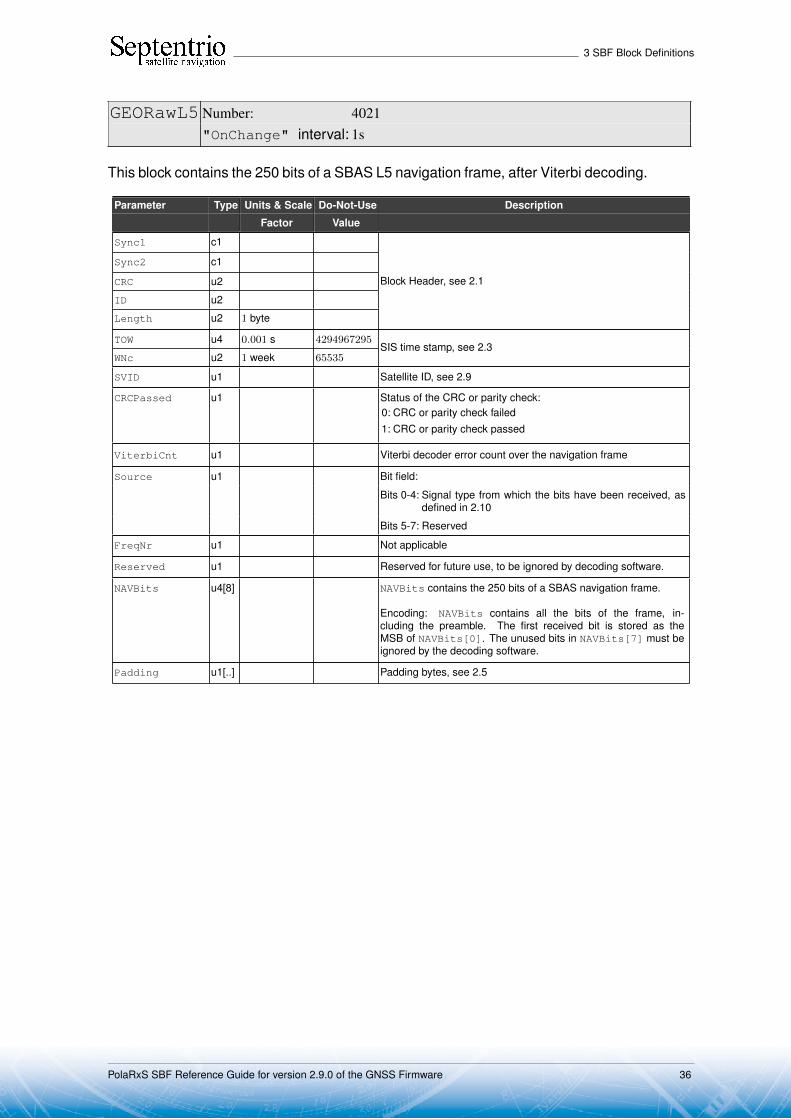
GEORawL5 Number: 4021"OnChange" interval: 1s
This block contains the 250 bits of a SBAS L5 navigation frame, after Viterbi decoding.
Parameter Type Units & Scale Do-Not-Use Description
Factor Value
Sync1 c1
Block Header, see 2.1
Sync2 c1
CRC u2
ID u2
Length u2 1 byte
TOW u4 0.001 s 4294967295SIS time stamp, see 2.3
WNc u2 1 week 65535
SVID u1 Satellite ID, see 2.9
CRCPassed u1 Status of the CRC or parity check:0: CRC or parity check failed1: CRC or parity check passed
ViterbiCnt u1 Viterbi decoder error count over the navigation frame
Source u1 Bit field:
Bits 0-4: Signal type from which the bits have been received, asdefined in 2.10
Bits 5-7: Reserved
FreqNr u1 Not applicable
Reserved u1 Reserved for future use, to be ignored by decoding software.
NAVBits u4[8] NAVBits contains the 250 bits of a SBAS navigation frame.
Encoding: NAVBits contains all the bits of the frame, in-cluding the preamble. The first received bit is stored as theMSB of NAVBits[0]. The unused bits in NAVBits[7] must beignored by the decoding software.
Padding u1[..] Padding bytes, see 2.5
PolaRxS SBF Reference Guide for version 2.9.0 of the GNSS Firmware 36
3 SBF Block Definitions
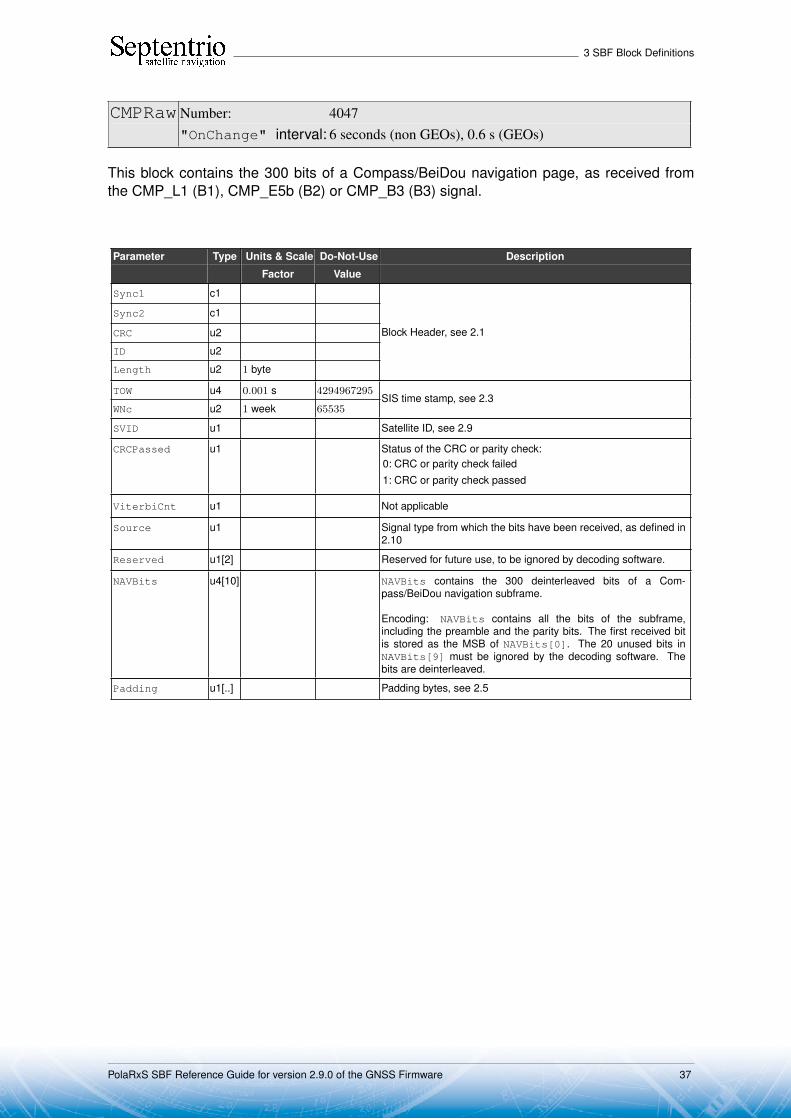
CMPRaw Number: 4047"OnChange" interval: 6 seconds (non GEOs), 0.6 s (GEOs)
This block contains the 300 bits of a Compass/BeiDou navigation page, as received fromthe CMP_L1 (B1), CMP_E5b (B2) or CMP_B3 (B3) signal.
Parameter Type Units & Scale Do-Not-Use Description
Factor Value
Sync1 c1
Block Header, see 2.1
Sync2 c1
CRC u2
ID u2
Length u2 1 byte
TOW u4 0.001 s 4294967295SIS time stamp, see 2.3
WNc u2 1 week 65535
SVID u1 Satellite ID, see 2.9
CRCPassed u1 Status of the CRC or parity check:0: CRC or parity check failed1: CRC or parity check passed
ViterbiCnt u1 Not applicable
Source u1 Signal type from which the bits have been received, as defined in2.10
Reserved u1[2] Reserved for future use, to be ignored by decoding software.
NAVBits u4[10] NAVBits contains the 300 deinterleaved bits of a Com-pass/BeiDou navigation subframe.
Encoding: NAVBits contains all the bits of the subframe,including the preamble and the parity bits. The first received bitis stored as the MSB of NAVBits[0]. The 20 unused bits inNAVBits[9] must be ignored by the decoding software. Thebits are deinterleaved.
Padding u1[..] Padding bytes, see 2.5
PolaRxS SBF Reference Guide for version 2.9.0 of the GNSS Firmware 37

3 SBF Block Definitions
QZSRawL1CA Number: 4066
"OnChange" interval: 6s
This block contains the 300 bits of a QZSS C/A subframe.
Parameter Type Units & Scale Do-Not-Use Description
Factor Value
Sync1 c1
Block Header, see 2.1
Sync2 c1
CRC u2
ID u2
Length u2 1 byte
TOW u4 0.001 s 4294967295SIS time stamp, see 2.3
WNc u2 1 week 65535
SVID u1 Satellite ID, see 2.9
CRCPassed u1 Status of the CRC or parity check:0: CRC or parity check failed1: CRC or parity check passed
Reserved u1 Reserved
Source u1 Bit field:
Bits 0-4: Signal type from which the bits have been received, asdefined in 2.10
Bits 5-7: Reserved
Reserved2 u1[2] Reserved for future use, to be ignored by decoding software.
NAVBits u4[10] NAVBits contains the 300 bits of a QZSS C/A subframe.
Encoding: Same as GPSRawCA block.
Padding u1[..] Padding bytes, see 2.5
PolaRxS SBF Reference Guide for version 2.9.0 of the GNSS Firmware 38

3 SBF Block Definitions
QZSRawL2C Number: 4067
"OnChange" interval: 12s
This block contains the 300 bits of a QZSS L2C CNAV subframe.
Parameter Type Units & Scale Do-Not-Use Description
Factor Value
Sync1 c1
Block Header, see 2.1
Sync2 c1
CRC u2
ID u2
Length u2 1 byte
TOW u4 0.001 s 4294967295SIS time stamp, see 2.3
WNc u2 1 week 65535
SVID u1 Satellite ID, see 2.9
CRCPassed u1 Status of the CRC or parity check:0: CRC or parity check failed1: CRC or parity check passed
ViterbiCnt u1 Viterbi decoder error count over the subframe
Source u1 Bit field:
Bits 0-4: Signal type from which the bits have been received, asdefined in 2.10
Bits 5-7: Reserved
Reserved u1[2] Reserved for future use, to be ignored by decoding software.
NAVBits u4[10] NAVBits contains the 300 bits of a QZSS CNAV subframe.
Encoding: NAVBits contains all the bits of the frame, in-cluding the preamble. The first received bit is stored as theMSB of NAVBits[0]. The unused bits in NAVBits[9] must beignored by the decoding software.
Padding u1[..] Padding bytes, see 2.5
PolaRxS SBF Reference Guide for version 2.9.0 of the GNSS Firmware 39

3 SBF Block Definitions
QZSRawL5 Number: 4068
"OnChange" interval: 6s
This block contains the 300 bits of a QZSS L5 CNAV subframe.
Parameter Type Units & Scale Do-Not-Use Description
Factor Value
Sync1 c1
Block Header, see 2.1
Sync2 c1
CRC u2
ID u2
Length u2 1 byte
TOW u4 0.001 s 4294967295SIS time stamp, see 2.3
WNc u2 1 week 65535
SVID u1 Satellite ID, see 2.9
CRCPassed u1 Status of the CRC or parity check:0: CRC or parity check failed1: CRC or parity check passed
ViterbiCnt u1 Viterbi decoder error count over the subframe
Source u1 Bit field:
Bits 0-4: Signal type from which the bits have been received, asdefined in 2.10
Bits 5-7: Reserved
Reserved u1[2] Reserved for future use, to be ignored by decoding software.
NAVBits u4[10] NAVBits contains the 300 bits of a QZSS CNAV subframe.
Encoding: NAVBits contains all the bits of the frame, in-cluding the preamble. The first received bit is stored as theMSB of NAVBits[0]. The unused bits in NAVBits[9] must beignored by the decoding software.
Padding u1[..] Padding bytes, see 2.5
PolaRxS SBF Reference Guide for version 2.9.0 of the GNSS Firmware 40
3 SBF Block Definitions
3.3 GPS Decoded Message Blocks
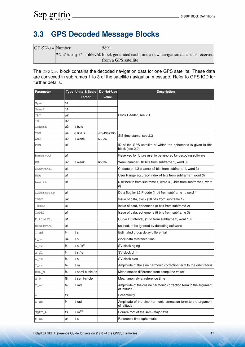
GPSNav Number: 5891"OnChange" interval: block generated each time a new navigation data set is received
from a GPS satellite
The GPSNav block contains the decoded navigation data for one GPS satellite. These dataare conveyed in subframes 1 to 3 of the satellite navigation message. Refer to GPS ICD forfurther details.
Parameter Type Units & Scale Do-Not-Use Description
Factor Value
Sync1 c1
Block Header, see 2.1
Sync2 c1
CRC u2
ID u2
Length u2 1 byte
TOW u4 0.001 s 4294967295SIS time stamp, see 2.3
WNc u2 1 week 65535
PRN u1 ID of the GPS satellite of which the ephemeris is given in thisblock (see 2.9)
Reserved u1 Reserved for future use, to be ignored by decoding software
WN u2 1 week 65535 Week number (10 bits from subframe 1, word 3)
CAorPonL2 u1 Code(s) on L2 channel (2 bits from subframe 1, word 3)
URA u1 User Range accuracy index (4 bits from subframe 1 word 3)
health u1 6-bit health from subframe 1, word 3 (6 bits from subframe 1, word3)
L2DataFlag u1 Data flag for L2 P-code (1 bit from subframe 1, word 4)
IODC u2 Issue of data, clock (10 bits from subframe 1)
IODE2 u1 Issue of data, ephemeris (8 bits from subframe 2)
IODE3 u1 Issue of data, ephemeris (8 bits from subframe 3)
FitIntFlg u1 Curve Fit Interval, (1 bit from subframe 2, word 10)
Reserved2 u1 unused, to be ignored by decoding software
T_gd f4 1 s Estimated group delay differential
t_oc u4 1 s clock data reference time
a_f2 f4 1 s / s2 SV clock aging
a_f1 f4 1 s / s SV clock drift
a_f0 f4 1 s SV clock bias
C_rs f4 1 m Amplitude of the sine harmonic correction term to the orbit radius
DEL_N f4 1 semi-circle / s Mean motion difference from computed value
M_0 f8 1 semi-circle Mean anomaly at reference time
C_uc f4 1 rad Amplitude of the cosine harmonic correction term to the argumentof latitude
e f8 Eccentricity
C_us f4 1 rad Amplitude of the sine harmonic correction term to the argumentof latitude
SQRT_A f8 1 m1/2 Square root of the semi-major axis
t_oe u4 1 s Reference time ephemeris
PolaRxS SBF Reference Guide for version 2.9.0 of the GNSS Firmware 41

3 SBF Block Definitions
C_ic f4 1 rad Amplitude of the cosine harmonic correction term to the angle ofinclination
OMEGA_0 f8 1 semi-circle Longitude of ascending node of orbit plane at weekly epoch
C_is f4 1 rad Amplitude of the sine harmonic correction term to the angle ofinclination
i_0 f8 1 semi-circle Inclination angle at reference time
C_rc f4 1 m Amplitude of the cosine harmonic correction term to the orbit ra-dius
omega f8 1 semi-circle Argument of perigee
OMEGADOT f4 1 semi-circle / s Rate of right ascension
IDOT f4 1 semi-circle / s Rate of inclination angle
WNt_oc u2 1 week WN associated with t_oc, modulo 1024
WNt_oe u2 1 week WN associated with t_oe, modulo 1024
Padding u1[..] Padding bytes, see 2.5
PolaRxS SBF Reference Guide for version 2.9.0 of the GNSS Firmware 42

3 SBF Block Definitions
GPSAlm Number: 5892"OnChange" interval: block generated each time a new almanac data set is received
from a GPS satellite
The GPSAlm block contains the decoded almanac data for one GPS satellite. These dataare conveyed in subframes 4 and 5 of the satellite navigation message. Refer to GPS ICDfor further details.
Parameter Type Units & Scale Do-Not-Use Description
Factor Value
Sync1 c1
Block Header, see 2.1
Sync2 c1
CRC u2
ID u2
Length u2 1 byte
TOW u4 0.001 s 4294967295SIS time stamp, see 2.3
WNc u2 1 week 65535
PRN u1 ID of the GPS satellite of which the almanac is given is this block(see 2.9)
Reserved u1 Reserved for future use, to be ignored by decoding software
e f4 Eccentricity
t_oa u4 1 s almanac reference time of week
delta_i f4 1 semi-circle Inclination angle at reference time, relative to i0 = 0.3 semi-circles
OMEGADOT f4 1 semi-circle / s Rate of right ascension
SQRT_A f4 1 m1/2 Square root of the semi-major axis
OMEGA_0 f4 1 semi-circle Longitude of ascending node of orbit plane at weekly epoch
omega f4 1 semi-circle Argument of perigee
M_0 f4 1 semi-circle Mean anomaly at reference time
a_f1 f4 1 s / s SV clock drift
a_f0 f4 1 s SV clock bias
WN_a u1 1 week Almanac reference week, to which t_oa is referenced
config u1 Anti-spoofing and satellite configuration (4 bits from subframe 4,page 25)
health8 u1 health on 8 bits from the almanac page
health6 u1 health summary on 6 bits (from subframe 4, page 25 and sub-frame 5 page 25)
Padding u1[..] Padding bytes, see 2.5
PolaRxS SBF Reference Guide for version 2.9.0 of the GNSS Firmware 43

3 SBF Block Definitions
GPSIon Number: 5893"OnChange" interval: block generated each time subframe 4, page 18, is received
from a GPS satellite
The GPSIon block contains the decoded ionosphere data (the Klobuchar coefficients).These data are conveyed in subframes 4, page 18 of the satellite navigation message. Referto GPS ICD for further details.
Parameter Type Units & Scale Do-Not-Use Description
Factor Value
Sync1 c1
Block Header, see 2.1
Sync2 c1
CRC u2
ID u2
Length u2 1 byte
TOW u4 0.001 s 4294967295SIS time stamp, see 2.3
WNc u2 1 week 65535
PRN u1 ID of the GPS satellite from which the coefficients have beenreceived (see 2.9)
Reserved u1 Reserved for future use, to be ignored by decoding software
alpha_0 f4 1 s vertical delay coefficient 0
alpha_1 f4 1 s / semi-circle vertical delay coefficient 1
alpha_2 f4 1 s / semi-circle2 vertical delay coefficient 2
alpha_3 f4 1 s / semi-circle3 vertical delay coefficient 3
beta_0 f4 1 s model period coefficient 0
beta_1 f4 1 s / semi-circle model period coefficient 1
beta_2 f4 1 s / semi-circle2 model period coefficient 2
beta_3 f4 1 s / semi-circle3 model period coefficient 3
Padding u1[..] Padding bytes, see 2.5
PolaRxS SBF Reference Guide for version 2.9.0 of the GNSS Firmware 44

3 SBF Block Definitions
GPSUtc Number: 5894"OnChange" interval: block generated each time subframe 4, page 18, is received
from a GPS satellite
The GPSUtc block contains the decoded UTC data. These data are conveyed in subframes4, page 18 of the satellite navigation message. Refer to GPS ICD for further details.
Parameter Type Units & Scale Do-Not-Use Description
Factor Value
Sync1 c1
Block Header, see 2.1
Sync2 c1
CRC u2
ID u2
Length u2 1 byte
TOW u4 0.001 s 4294967295SIS time stamp, see 2.3
WNc u2 1 week 65535
PRN u1 ID of the GPS satellite from which these UTC parameters havebeen received (see 2.9)
Reserved u1 Reserved for future use, to be ignored by decoding software
A_1 f4 1 s / s first order term of polynomial
A_0 f8 1 s constant term of polynomial
t_ot u4 1 s reference time for UTC data
WN_t u1 1 week UTC reference week number, to which t_ot is referenced
DEL_t_LS i1 1 s Delta time due to leap seconds whenever the effectivity time isnot in the past
WN_LSF u1 1 week Effectivity time of leap second (week)
DN u1 1 day Effectivity time of leap second (day)
DEL_t_LSF i1 1 s Delta time due to leap seconds whenever the effectivity time is inthe past
Padding u1[..] Padding bytes, see 2.5
PolaRxS SBF Reference Guide for version 2.9.0 of the GNSS Firmware 45

3 SBF Block Definitions
3.4 GLONASS Decoded Message Blocks
GLONav Number: 4004"OnChange" interval: block generated each time a new navigation data set is received
from a GLONASS satellite
The GLONav block contains the decoded ephemeris data for one GLONASS satellite.
Parameter Type Units & Scale Do-Not-Use Description
Factor Value
Sync1 c1
Block Header, see 2.1
Sync2 c1
CRC u2
ID u2
Length u2 1 byte
TOW u4 0.001 s 4294967295SIS time stamp, see 2.3
WNc u2 1 week 65535
SVID u1 ID of the GLONASS satellite for which ephemeris is provided inthis block (see 2.9).
FreqNr u1 Frequency number of the GLONASS satellite for which ephemerisis provided in this block (see 2.9).
X f8 1000 m x-component of satellite position in PZ-90.02
Y f8 1000 m y-component of satellite position in PZ-90.02
Z f8 1000 m z-component of satellite position in PZ-90.02
Dx f4 1000 m / s x-component of satellite velocity in PZ-90.02
Dy f4 1000 m / s y-component of satellite velocity in PZ-90.02
Dz f4 1000 m / s z-component of satellite velocity in PZ-90.02
Ddx f4 1000 m / s2 x-component of satellite acceleration in PZ-90.02
Ddy f4 1000 m / s2 y-component of satellite acceleration in PZ-90.02
Ddz f4 1000 m / s2 z-component of satellite acceleration in PZ-90.02
gamma f4 1 Hz / Hz γn(tb):relative deviation of predicted carrier frequency
tau f4 1 s τn(tb): time correction to GLONASS time
dtau f4 1 s ∆τn: time difference between L2 and L1 sub-band
t_oe u4 1 s reference time-of-week in GPS time frame
WN_toe u2 1 week reference week number in GPS time frame (modulo 1024)
P1 u1 1 minute time interval between adjacent values of tb
P2 u1 1-bit odd/even flag of tb
E u1 1 day age of data
B u1 3-bit health flag, satellite unhealthy if MSB set
tb u2 1 minute time of day (center of validity interval)
M u1 2-bit GLONASS-M satellite identifier (01, otherwise 00)
P u1 2-bit mode of computation of time parameters
l u1 1-bit health flag, 0=healthy, 1=unhealthy
P4 u1 1-bit ’updated’ flag of ephemeris data
N_T u2 1 day current day number within 4-year interval
F_T u2 0.01 m predicted user range accuracy at time tb
PolaRxS SBF Reference Guide for version 2.9.0 of the GNSS Firmware 46
3 SBF Block Definitions
Padding u1[..] Padding bytes, see 2.5
PolaRxS SBF Reference Guide for version 2.9.0 of the GNSS Firmware 47

3 SBF Block Definitions
GLOAlm Number: 4005"OnChange" interval: block generated each time a new almanac data set is received
from a GLONASS satellite
The GLOAlm block contains the decoded navigation data for one GLONASS satellite.
Parameter Type Units & Scale Do-Not-Use Description
Factor Value
Sync1 c1
Block Header, see 2.1
Sync2 c1
CRC u2
ID u2
Length u2 1 byte
TOW u4 0.001 s 4294967295SIS time stamp, see 2.3
WNc u2 1 week 65535
SVID u1 ID of the GLONASS satellite for which almanac is provided inthis block (see 2.9).
FreqNr u1 Frequency number of the GLONASS satellite for which almanacis provided in this block (see 2.9).This number corresponds to the HA
n parameter in theGLONASS ICD.
epsilon f4 εAn : orbit eccentricity
t_oa u4 1 s Reference time-of-week in GPS time frame
Delta_i f4 1 semi-circle ∆ iAn : correction to inclination
lambda f4 1 semi-circle λAn : Longitude of first ascending node
t_ln f4 1 s tAλ n: time of first ascending node passage
omega f4 1 semi-circle ωAn : argument of perigee
Delta_T f4 1 s / orbit-period ∆ TAn : correction to mean Draconian period
dDelta_T f4 1 s / orbit-period2 d∆ TAn : rate of change correction to mean Draconian period
tau f4 1 s τAn : coarse correction to satellite time
WN_a u1 1 week Reference week in GPS time frame (modulo 256)
C u1 CnA: 1-bit general health flag (1 indicates healthy)
N u2 1 day NA: calendar day number within 4 year period
M u1 MnA: 2-bit GLONASS-M satellite identifier
N_4 u1 N4: 4 year interval number, starting from 1996
Padding u1[..] Padding bytes, see 2.5
PolaRxS SBF Reference Guide for version 2.9.0 of the GNSS Firmware 48
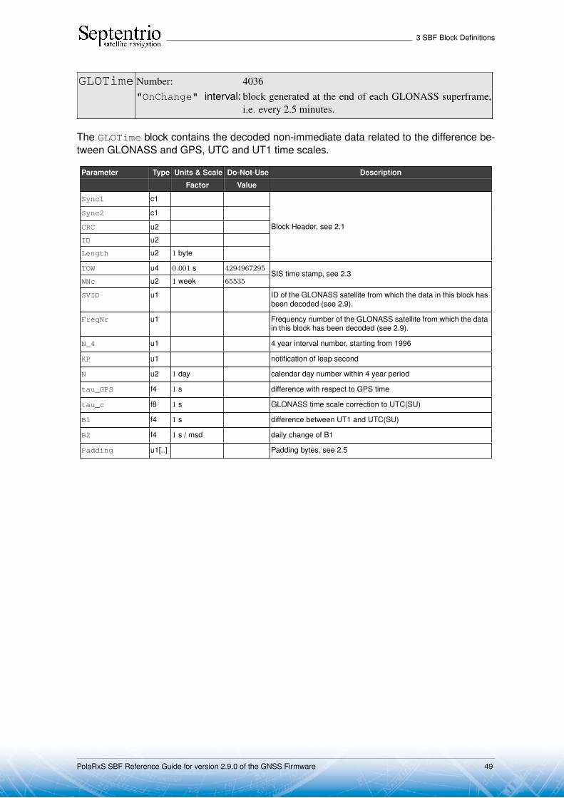
3 SBF Block Definitions
GLOTime Number: 4036"OnChange" interval: block generated at the end of each GLONASS superframe,
i.e. every 2.5 minutes.
The GLOTime block contains the decoded non-immediate data related to the difference be-tween GLONASS and GPS, UTC and UT1 time scales.
Parameter Type Units & Scale Do-Not-Use Description
Factor Value
Sync1 c1
Block Header, see 2.1
Sync2 c1
CRC u2
ID u2
Length u2 1 byte
TOW u4 0.001 s 4294967295SIS time stamp, see 2.3
WNc u2 1 week 65535
SVID u1 ID of the GLONASS satellite from which the data in this block hasbeen decoded (see 2.9).
FreqNr u1 Frequency number of the GLONASS satellite from which the datain this block has been decoded (see 2.9).
N_4 u1 4 year interval number, starting from 1996
KP u1 notification of leap second
N u2 1 day calendar day number within 4 year period
tau_GPS f4 1 s difference with respect to GPS time
tau_c f8 1 s GLONASS time scale correction to UTC(SU)
B1 f4 1 s difference between UT1 and UTC(SU)
B2 f4 1 s / msd daily change of B1
Padding u1[..] Padding bytes, see 2.5
PolaRxS SBF Reference Guide for version 2.9.0 of the GNSS Firmware 49

3 SBF Block Definitions
3.5 Galileo Decoded Message Blocks
GALNav Number: 4002"OnChange" interval: output each time a new navigation data batch is decoded.
The GalNav block contains the following decoded navigation data for one Galileo satellite:
• orbital elements and clock corrections• health, Signal-In-Space Accuracy (SISA) indexes and Broadcast Group Delays (BGDs)
for each carrier or carrier combinations.
The interpretation of the clock correction parameters (t_oc, a_f0, a_f1, a_f2) dependson the value of the Source field:
Source Message type Applicable Clock Model
2 I/NAV (L1,E5b)
16 F/NAV (L1,E5a)
If the receiver is decoding both the I/NAV and the F/NAV data stream, it will output a GalNavblock for the I/NAV stream, containing the (L1, E5b) clock model, and a different GalNavblock for the F/NAV stream, containing the (L1, E5a) clock model.
Depending on the message type being decoded, some health, SISA or BGD valuesmay not be available (in that case they are set to their respective Do-Not-Use values). Thefollowing health, SISA and BGD values are guaranteed to be available for a given value ofthe Source field:
Source Health, SISA and BGD availability
2 (I/NAV) At least L1-BDVS, L1-BHS, E5bDVS,E5bHS, SISA_L1E5b and BGD_L1E5b are available
16 (F/NAV) At least E5aDVS,E5aHS, SISA_L1E5a and BGD_L1E5a are available
The IODNav field identifies the issue of data. All orbital elements, clock parameters andSISA values in the block are guaranteed to refer to the same data batch identified byIODNav. The fields Health_OSSOL, BGD_L1E5a, BGD_L1E5b and CNAVenc are notcovered by the issue of data, and the block simply contains the latest received value.
Please refer to the Galileo Signal-In-Space ICD for the interpretation and usage ofthe parameters contained in this SBF block.
Parameter Type Units & Scale Do-Not-Use Description
Factor Value
Sync1 c1
Block Header, see 2.1
Sync2 c1
CRC u2
ID u2
Length u2 1 byte
TOW u4 0.001 s 4294967295SIS time stamp, see 2.3
WNc u2 1 week 65535
SVID u1 SVID of the Galileo satellite (see 2.9)
PolaRxS SBF Reference Guide for version 2.9.0 of the GNSS Firmware 50

3 SBF Block Definitions
Source u1 See table above: this field indicates how to interpret the clockcorrection parameters.
SQRT_A f8 1 m1/2 Square root of the semi-major axis
M_0 f8 1 semi-circle Mean anomaly at reference time
e f8 Eccentricity
i_0 f8 1 semi-circle Inclination angle at reference time
omega f8 1 semi-circle Argument of perigee
OMEGA_0 f8 1 semi-circle Longitude of ascending node of orbit plane at weekly epoch
OMEGADOT f4 1 semi-circle / s Rate of right ascension
IDOT f4 1 semi-circle / s Rate of inclination angle
DEL_N f4 1 semi-circle / s Mean motion difference from computed value
C_uc f4 1 rad Amplitude of the cosine harmonic correction term to the argumentof latitude
C_us f4 1 rad Amplitude of the sine harmonic correction term to the argumentof latitude
C_rc f4 1 m Amplitude of the cosine harmonic correction term to the orbit ra-dius
C_rs f4 1 m Amplitude of the sine harmonic correction term to the orbit radius
C_ic f4 1 rad Amplitude of the sine harmonic correction term to the angle ofinclination
C_is f4 1 rad Amplitude of the cosine harmonic correction term to the angle ofinclination
t_oe u4 1 s Reference time, ephemeris
t_oc u4 1 s Reference time, clock. The Source field indicates which clockmodel t_oc refers to.
a_f2 f4 1 s / s2 SV clock aging. The Source field indicates which clock modela_f2 refers to.
a_f1 f4 1 s / s SV clock drift. The Source field indicates which clock modela_f1 refers to.
a_f0 f8 1 s SV clock bias. The Source field indicates which clock modela_f0 refers to.
WNt_oe u2 1 week WN associated with t_oe, modulo 4096
WNt_oc u2 1 week WN associated with t_oc, modulo 4096
IODnav u2 Issue of data, navigation (10 bits)
Health_OSSOL u2 Bit field indicating the last received Health Status (HS) and DataValidity Status (DVS) of the E5a, E5b and L1-B signals:
Bit 0: If set, bits 1 to 3 are valid, otherwise they must beignored.
Bit 1: 1-bit L1-BDVS
Bits 2-3: 2-bit L1-BHS
Bit 4: If set, bits 5 to 7 are valid, otherwise they must beignored.
Bit 5: 1-bit E5bDVS
Bits 6-7: 2-bit E5bHS
Bit 8: If set, bits 9 to 11 are valid, otherwise they must beignored.
Bit 9: 1-bit E5aDVS
Bits 10-11: 2-bit E5aHS
Bits 12-15: Reserved
Health_PRS u1 Reserved
PolaRxS SBF Reference Guide for version 2.9.0 of the GNSS Firmware 51
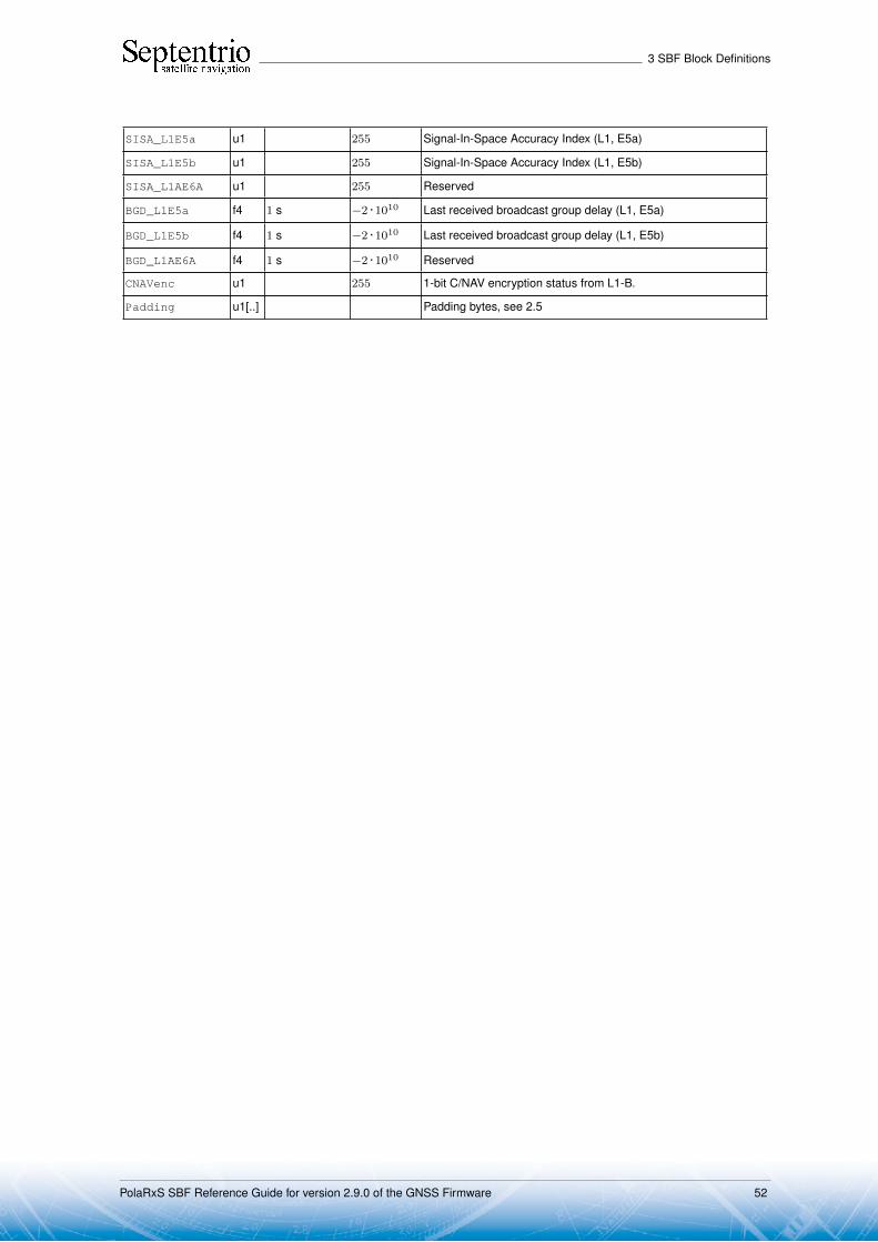
3 SBF Block Definitions
SISA_L1E5a u1 255 Signal-In-Space Accuracy Index (L1, E5a)
SISA_L1E5b u1 255 Signal-In-Space Accuracy Index (L1, E5b)
SISA_L1AE6A u1 255 Reserved
BGD_L1E5a f4 1 s −2 · 1010 Last received broadcast group delay (L1, E5a)
BGD_L1E5b f4 1 s −2 · 1010 Last received broadcast group delay (L1, E5b)
BGD_L1AE6A f4 1 s −2 · 1010 Reserved
CNAVenc u1 255 1-bit C/NAV encryption status from L1-B.
Padding u1[..] Padding bytes, see 2.5
PolaRxS SBF Reference Guide for version 2.9.0 of the GNSS Firmware 52

3 SBF Block Definitions
GALAlm Number: 4003"OnChange" interval: output each time a new almanac set is received for a satellite.
The GalAlm block contains the decoded almanac data for one Galileo satellite.
Parameter Type Units & Scale Do-Not-Use Description
Factor Value
Sync1 c1
Block Header, see 2.1
Sync2 c1
CRC u2
ID u2
Length u2 1 byte
TOW u4 0.001 s 4294967295SIS time stamp, see 2.3
WNc u2 1 week 65535
SVID u1 SVID of the Galileo satellite from which these almanac parame-ters have been received (see 2.9)
Source u1 See corresponding field in the GalNav block.
Source can take the value 18 to indicate that the almanacdata contained in this block has been merged from INAV andFNAV pages.
e f4 Eccentricity
t_oa u4 1 s almanac reference time of week
delta_i f4 1 semi-circle Inclination angle at reference time, relative to nominal
OMEGADOT f4 1 semi-circle / s Rate of right ascension
SQRT_A f4 1 m1/2 Square root of the semi-major axis, relative to nominal
OMEGA_0 f4 1 semi-circle Longitude of ascending node of orbit plane at weekly epoch
omega f4 1 semi-circle Argument of perigee
M_0 f4 1 semi-circle Mean anomaly at reference time
a_f1 f4 1 s / s SV clock drift
a_f0 f4 1 s SV clock bias
WN_a u1 1 week 2-bit almanac reference week
SVID_A u1 SVID of the Galileo satellite of which the almanac parameters areprovided in this block (see 2.9 for the SVID numbering conven-tion).
PolaRxS SBF Reference Guide for version 2.9.0 of the GNSS Firmware 53

3 SBF Block Definitions
health u2 Bit field indicating the health status (HS) of the E5a, E5b, L1-B,L1-A and E6-A signals:
Bit 0: If set, bits 1 and 2 are valid, otherwise they must beignored.
Bits 1-2: 2-bit L1-BHS
Bit 3: If set, bits 4 and 5 are valid, otherwise they must beignored.
Bits 4-5: 2-bit E5bHS
Bit 6: If set, bits 7 and 8 are valid, otherwise they must beignored.
Bits 7-8: 2-bit E5aHS
Bit 9: If set, bits 10 and 11 are valid, otherwise they must beignored.
Bits 10-11: 2-bit L1-AHS
Bit 12: If set, bits 13 and 14 are valid, otherwise they must beignored.
Bits 13-14: 2-bit E6-AHS
Bit 15: Reserved
IODa u1 4-bit Issue of Data for the almanac.
Padding u1[..] Padding bytes, see 2.5
PolaRxS SBF Reference Guide for version 2.9.0 of the GNSS Firmware 54
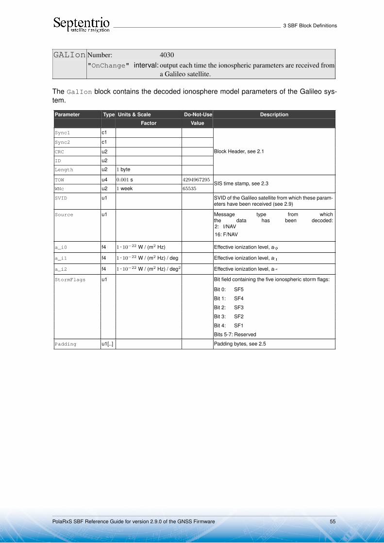
3 SBF Block Definitions
GALIon Number: 4030"OnChange" interval: output each time the ionospheric parameters are received from
a Galileo satellite.
The GalIon block contains the decoded ionosphere model parameters of the Galileo sys-tem.
Parameter Type Units & Scale Do-Not-Use Description
Factor Value
Sync1 c1
Block Header, see 2.1
Sync2 c1
CRC u2
ID u2
Length u2 1 byte
TOW u4 0.001 s 4294967295SIS time stamp, see 2.3
WNc u2 1 week 65535
SVID u1 SVID of the Galileo satellite from which these param-eters have been received (see 2.9)
Source u1 Message type from whichthe data has been decoded:2: I/NAV16: F/NAV
a_i0 f4 1 · 10−22 W / (m2 Hz) Effective ionization level, ai0
a_i1 f4 1 · 10−22 W / (m2 Hz) / deg Effective ionization level, ai1
a_i2 f4 1 · 10−22 W / (m2 Hz) / deg2 Effective ionization level, ai2
StormFlags u1 Bit field containing the five ionospheric storm flags:
Bit 0: SF5
Bit 1: SF4
Bit 2: SF3
Bit 3: SF2
Bit 4: SF1
Bits 5-7: Reserved
Padding u1[..] Padding bytes, see 2.5
PolaRxS SBF Reference Guide for version 2.9.0 of the GNSS Firmware 55

3 SBF Block Definitions
GALUtc Number: 4031"OnChange" interval: output each time the UTC offset parameters are received from
a Galileo satellite.
The GalUtc block contains the decoded UTC parameter information.
Parameter Type Units & Scale Do-Not-Use Description
Factor Value
Sync1 c1
Block Header, see 2.1
Sync2 c1
CRC u2
ID u2
Length u2 1 byte
TOW u4 0.001 s 4294967295SIS time stamp, see 2.3
WNc u2 1 week 65535
SVID u1 SVID of the Galileo satellite from which these parameters havebeen received (see 2.9)
Source u1 Message type from which the data has been decoded:2: I/NAV16: F/NAV
A_1 f4 1 s / s first order term of polynomial
A_0 f8 1 s constant term of polynomial
t_ot u4 1 s reference time of week for UTC data
WN_ot u1 1 week UTC reference week number, to which t_ot is referenced
DEL_t_LS i1 1 s Delta time due to leap seconds whenever the effectivity time isnot in the past
WN_LSF u1 1 week Effectivity time of leap second (week)
DN u1 1 day Effectivity time of leap second (day)
DEL_t_LSF i1 1 s Delta time due to leap seconds whenever the effectivity time is inthe past
Padding u1[..] Padding bytes, see 2.5
PolaRxS SBF Reference Guide for version 2.9.0 of the GNSS Firmware 56

3 SBF Block Definitions
GALGstGps Number: 4032
"OnChange" interval: output each time valid GST-GPS offset parameters arereceived from a Galileo satellite.
This block contains the decoded GPS to Galileo System Time offset parameters. This blockis only output if these parameters are valid in the navigation page (i.e. if they are not set to"all ones").
Parameter Type Units & Scale Do-Not-Use Description
Factor Value
Sync1 c1
Block Header, see 2.1
Sync2 c1
CRC u2
ID u2
Length u2 1 byte
TOW u4 0.001 s 4294967295SIS time stamp, see 2.3
WNc u2 1 week 65535
SVID u1 SVID of the Galileo satellite from which these parameters havebeen received (see 2.9)
Source u1 Message type from which the data has been decoded:2: I/NAV16: F/NAV
A_1G f4 1 s / s Rate of change of the offset
A_0G f4 1 s Constant term of the offset
t_oG u4 1 s Reference time of week
WN_oG u1 1 week 6-bit reference week number.
Padding u1[..] Padding bytes, see 2.5
PolaRxS SBF Reference Guide for version 2.9.0 of the GNSS Firmware 57
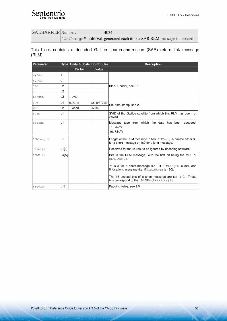
3 SBF Block Definitions
GALSARRLM Number: 4034"OnChange" interval: generated each time a SAR RLM message is decoded.
This block contains a decoded Galileo search-and-rescue (SAR) return link message(RLM).
Parameter Type Units & Scale Do-Not-Use Description
Factor Value
Sync1 c1
Block Header, see 2.1
Sync2 c1
CRC u2
ID u2
Length u2 1 byte
TOW u4 0.001 s 4294967295SIS time stamp, see 2.3
WNc u2 1 week 65535
SVID u1 SVID of the Galileo satellite from which this RLM has been re-ceived.
Source u1 Message type from which the data has been decoded:2: I/NAV16: F/NAV
RLMLength u1 Length of the RLM message in bits. RLMLength can be either 80for a short message or 160 for a long message.
Reserved u1[3] Reserved for future use, to be ignored by decoding software
RLMBits u4[N] Bits in the RLM message, with the first bit being the MSB ofRLMBits[0].
N is 3 for a short message (i.e. if RLMLength is 80), and5 for a long message (i.e. if RLMLength is 160).
The 16 unused bits of a short message are set to 0. Thesebits correspond to the 16 LSBs of RLMBits[2].
Padding u1[..] Padding bytes, see 2.5
PolaRxS SBF Reference Guide for version 2.9.0 of the GNSS Firmware 58

3 SBF Block Definitions
3.6 Compass/BeiDou Decoded Message Blocks
CMPNav Number: 4081"OnChange" interval: block generated each time a new navigation data set is received
from a Compass/BeiDou satellite
The CMPNav block contains the decoded navigation data for one Compass/BeiDou satel-lite. The navigation data is received from the B1I signal modulated by either the D1 or D2message.
Parameter Type Units & Scale Do-Not-Use Description
Factor Value
Sync1 c1
Block Header, see 2.1
Sync2 c1
CRC u2
ID u2
Length u2 1 byte
TOW u4 0.001 s 4294967295SIS time stamp, see 2.3
WNc u2 1 week 65535
PRN u1 ID of the Compass/BeiDou satellite of which the ephemeris isgiven in this block (see 2.9)
Reserved u1 Reserved for future use, to be ignored by decoding software
WN u2 1 week BeiDou week number as received from the navigation message(from 0 to 8191)
URA u1 User range accuracy index (4-bit value)
SatH1 u1 1-bit autonomous health
IODC u1 Issue of data, clock (5 bits)
IODE u1 Issue of data, ephemeris (5 bits)
Reserved2 u2 unused, to be ignored by decoding software
T_GD1 f4 1 s B1 equipment group delay differential
T_GD2 f4 1 s −2 · 1010 B2 equipment group delay differential (set to the do-not-use valuewhen unknown)
t_oc u4 1 s clock data reference time, in BeiDou system time (lagging GPStime by 14 seconds).
a_f2 f4 1 s / s2 SV clock aging
a_f1 f4 1 s / s SV clock drift
a_f0 f4 1 s SV clock bias
C_rs f4 1 m Amplitude of the sine harmonic correction term to the orbit radius
DEL_N f4 1 semi-circle / s Mean motion difference from computed value
M_0 f8 1 semi-circle Mean anomaly at reference time
C_uc f4 1 rad Amplitude of the cosine harmonic correction term to the argumentof latitude
e f8 Eccentricity
C_us f4 1 rad Amplitude of the sine harmonic correction term to the argumentof latitude
SQRT_A f8 1 m1/2 Square root of the semi-major axis
t_oe u4 1 s Reference time ephemeris, in BeiDou system time (lagging GPStime by 14 seconds).
PolaRxS SBF Reference Guide for version 2.9.0 of the GNSS Firmware 59

3 SBF Block Definitions
C_ic f4 1 rad Amplitude of the cosine harmonic correction term to the angle ofinclination
OMEGA_0 f8 1 semi-circle Longitude of ascending node of orbit plane at weekly epoch
C_is f4 1 rad Amplitude of the sine harmonic correction term to the angle ofinclination
i_0 f8 1 semi-circle Inclination angle at reference time
C_rc f4 1 m Amplitude of the cosine harmonic correction term to the orbit ra-dius
omega f8 1 semi-circle Argument of perigee
OMEGADOT f4 1 semi-circle / s Rate of right ascension
IDOT f4 1 semi-circle / s Rate of inclination angle
WNt_oc u2 1 week BeiDou week number associated with t_oc, modulo 8192. Notethat this value relates to the BeiDou system time.
WNt_oe u2 1 week BeiDou week number associated with t_oe, modulo 8192. Notethat this values relates to the BeiDou system time.
Padding u1[..] Padding bytes, see 2.5
PolaRxS SBF Reference Guide for version 2.9.0 of the GNSS Firmware 60

3 SBF Block Definitions
3.7 QZSS Decoded Message Blocks
QZSNav Number: 4095
"OnChange" interval: block generated each time a new navigation data set is receivedfrom a QZSS satellite
The QZSNav block contains the decoded navigation data for one QZSS satellite. The data isdecoded from the navigation message transmitted in the L1 C/A signal. Refer to the QZSSICD for further details.
Parameter Type Units & Scale Do-Not-Use Description
Factor Value
Sync1 c1
Block Header, see 2.1
Sync2 c1
CRC u2
ID u2
Length u2 1 byte
TOW u4 0.001 s 4294967295SIS time stamp, see 2.3
WNc u2 1 week 65535
PRN u1 ID of the QZSS satellite of which the ephemeris is given in thisblock (see 2.9)
Reserved u1 Reserved for future use, to be ignored by decoding software
WN u2 1 week 65535 Week number (10 bits from subframe 1, word 3)
CAorPonL2 u1 Code(s) on L2 channel (2 bits from subframe 1, word 3). Always2 for QZSS satellites.
URA u1 User Range accuracy index (4 bits from subframe 1 word 3)
health u1 6-bit health from subframe 1, word 3 (6 bits from subframe 1, word3)
L2DataFlag u1 Data flag for L2 P-code (1 bit from subframe 1, word 4). Always 1for QZSS satellites.
IODC u2 Issue of data, clock (10 bits from subframe 1)
IODE2 u1 Issue of data, ephemeris (8 bits from subframe 2)
IODE3 u1 Issue of data, ephemeris (8 bits from subframe 3)
FitIntFlg u1 Curve Fit Interval, (1 bit from subframe 2, word 10)
Reserved2 u1 unused, to be ignored by decoding software
T_gd f4 1 s −2 · 1010 Estimated group delay differential
t_oc u4 1 s clock data reference time
a_f2 f4 1 s / s2 SV clock aging
a_f1 f4 1 s / s SV clock drift
a_f0 f4 1 s SV clock bias
C_rs f4 1 m Amplitude of the sine harmonic correction term to the orbit radius
DEL_N f4 1 semi-circle / s Mean motion difference from computed value
M_0 f8 1 semi-circle Mean anomaly at reference time
C_uc f4 1 rad Amplitude of the cosine harmonic correction term to the argumentof latitude
e f8 Eccentricity
C_us f4 1 rad Amplitude of the sine harmonic correction term to the argumentof latitude
PolaRxS SBF Reference Guide for version 2.9.0 of the GNSS Firmware 61

3 SBF Block Definitions
SQRT_A f8 1 m1/2 Square root of the semi-major axis
t_oe u4 1 s Reference time ephemeris
C_ic f4 1 rad Amplitude of the cosine harmonic correction term to the angle ofinclination
OMEGA_0 f8 1 semi-circle Longitude of ascending node of orbit plane at weekly epoch
C_is f4 1 rad Amplitude of the sine harmonic correction term to the angle ofinclination
i_0 f8 1 semi-circle Inclination angle at reference time
C_rc f4 1 m Amplitude of the cosine harmonic correction term to the orbit ra-dius
omega f8 1 semi-circle Argument of perigee
OMEGADOT f4 1 semi-circle / s Rate of right ascension
IDOT f4 1 semi-circle / s Rate of inclination angle
WNt_oc u2 1 week WN associated with t_oc, modulo 1024
WNt_oe u2 1 week WN associated with t_oe, modulo 1024
Padding u1[..] Padding bytes, see 2.5
PolaRxS SBF Reference Guide for version 2.9.0 of the GNSS Firmware 62

3 SBF Block Definitions
3.8 SBAS Decoded Message BlocksIn the SBAS message blocks described in the next pages, the time tag reported in the TOWand WNc fields always refers to the end of the last bit of the message. To get the time oftransmission of the beginning of the first bit of the message, which is equal to the time ofapplicability of the SBAS navigation data, the user must subtract 1 second from TOW.
The receiver is receiving SBAS data from all the tracked SBAS satellites, but decoding ofthe messages is performed only from the L1 signal of the satellite that is currently used tocompute corrections. Therefore all the SBF blocks in the next pages are available only forthis satellite.
Note that a user interested in the actual SBAS corrections that have been applied in theposition computation can also use the GEOCorrections block.
PolaRxS SBF Reference Guide for version 2.9.0 of the GNSS Firmware 63
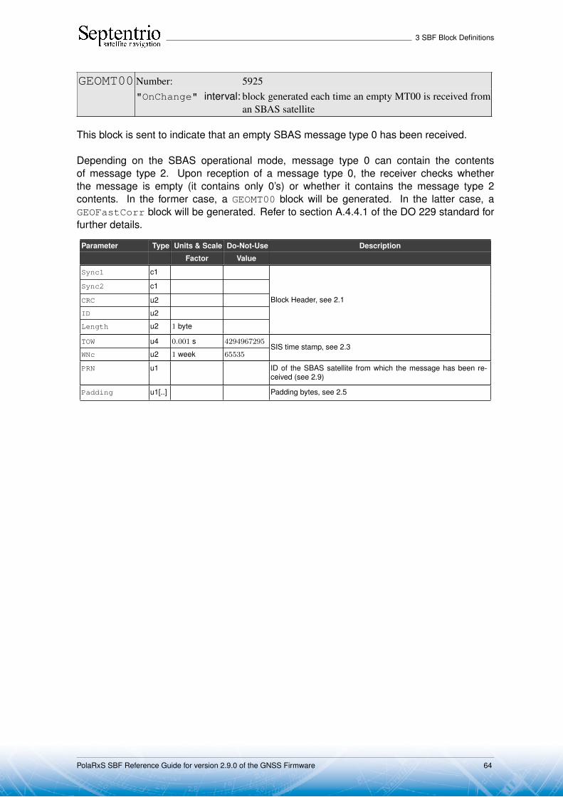
3 SBF Block Definitions
GEOMT00 Number: 5925"OnChange" interval: block generated each time an empty MT00 is received from
an SBAS satellite
This block is sent to indicate that an empty SBAS message type 0 has been received.
Depending on the SBAS operational mode, message type 0 can contain the contentsof message type 2. Upon reception of a message type 0, the receiver checks whetherthe message is empty (it contains only 0’s) or whether it contains the message type 2contents. In the former case, a GEOMT00 block will be generated. In the latter case, aGEOFastCorr block will be generated. Refer to section A.4.4.1 of the DO 229 standard forfurther details.
Parameter Type Units & Scale Do-Not-Use Description
Factor Value
Sync1 c1
Block Header, see 2.1
Sync2 c1
CRC u2
ID u2
Length u2 1 byte
TOW u4 0.001 s 4294967295SIS time stamp, see 2.3
WNc u2 1 week 65535
PRN u1 ID of the SBAS satellite from which the message has been re-ceived (see 2.9)
Padding u1[..] Padding bytes, see 2.5
PolaRxS SBF Reference Guide for version 2.9.0 of the GNSS Firmware 64

3 SBF Block Definitions
GEOPRNMask Number: 5926"OnChange" interval: block generated each time MT01 is received from an
SBAS satellite
This block contains the decoded PRN mask transmitted in SBAS message type 1. Refer tosection A.4.4.2 of the DO 229 standard for further details.
Parameter Type Units & Scale Do-Not-Use Description
Factor Value
Sync1 c1
Block Header, see 2.1
Sync2 c1
CRC u2
ID u2
Length u2 1 byte
TOW u4 0.001 s 4294967295SIS time stamp, see 2.3
WNc u2 1 week 65535
PRN u1 ID of the SBAS satellite from which the message has beenreceived (see 2.9)
IODP u1 Issue of data - PRN.
NbrPRNs u1 Number of PRNs designated in the mask.
PRNMask u1[NbrPRNs] List of the PRNs in the PRN mask.
PRNMask[0] is the first PRN designated in the PRNmask (from 1 to 210),PRNMask[1] is the 2nd PRN designated in the PRNmask,etc...
Padding u1[..] Padding bytes, see 2.5
PolaRxS SBF Reference Guide for version 2.9.0 of the GNSS Firmware 65
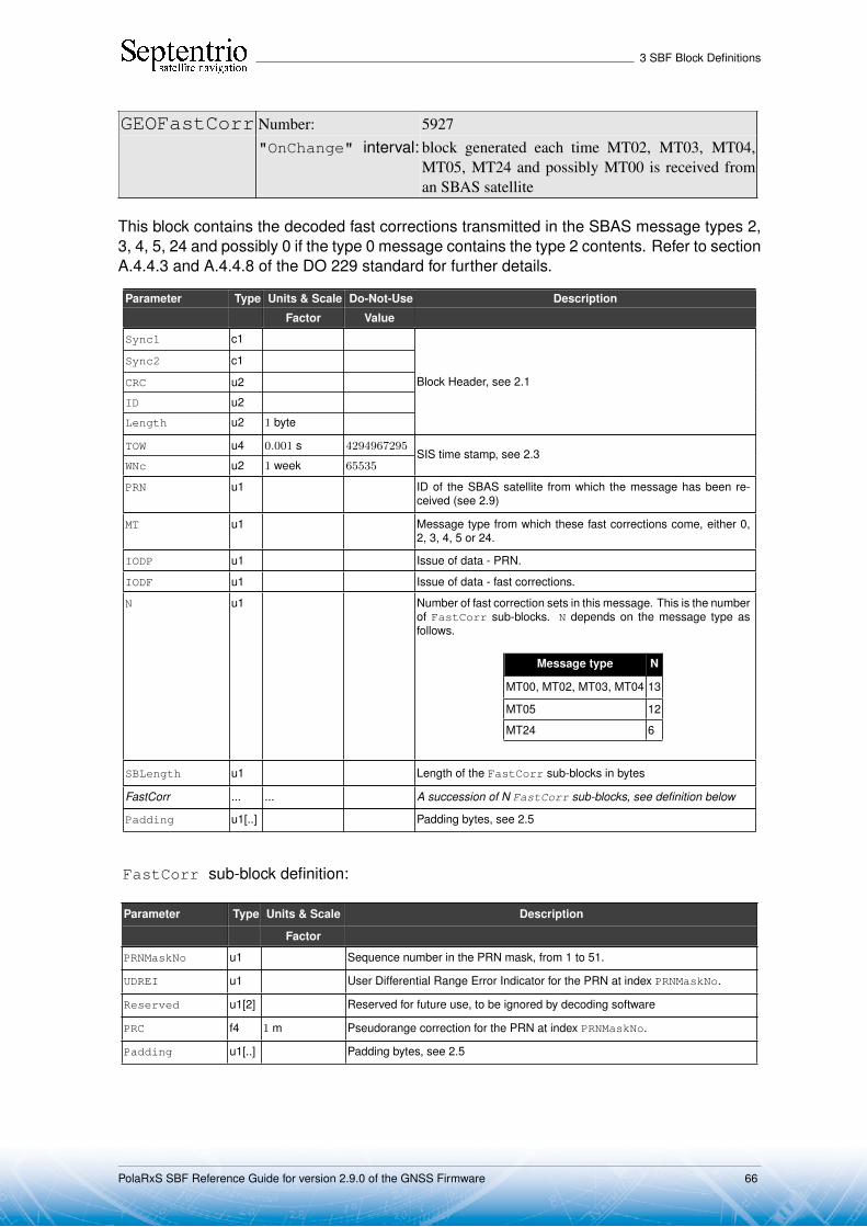
3 SBF Block Definitions
GEOFastCorr Number: 5927"OnChange" interval: block generated each time MT02, MT03, MT04,
MT05, MT24 and possibly MT00 is received froman SBAS satellite
This block contains the decoded fast corrections transmitted in the SBAS message types 2,3, 4, 5, 24 and possibly 0 if the type 0 message contains the type 2 contents. Refer to sectionA.4.4.3 and A.4.4.8 of the DO 229 standard for further details.
Parameter Type Units & Scale Do-Not-Use Description
Factor Value
Sync1 c1
Block Header, see 2.1
Sync2 c1
CRC u2
ID u2
Length u2 1 byte
TOW u4 0.001 s 4294967295SIS time stamp, see 2.3
WNc u2 1 week 65535
PRN u1 ID of the SBAS satellite from which the message has been re-ceived (see 2.9)
MT u1 Message type from which these fast corrections come, either 0,2, 3, 4, 5 or 24.
IODP u1 Issue of data - PRN.
IODF u1 Issue of data - fast corrections.
N u1 Number of fast correction sets in this message. This is the numberof FastCorr sub-blocks. N depends on the message type asfollows.
Message type N
MT00, MT02, MT03, MT04 13
MT05 12
MT24 6
SBLength u1 Length of the FastCorr sub-blocks in bytes
FastCorr ... ... A succession of N FastCorr sub-blocks, see definition below
Padding u1[..] Padding bytes, see 2.5
FastCorr sub-block definition:
Parameter Type Units & Scale Description
Factor
PRNMaskNo u1 Sequence number in the PRN mask, from 1 to 51.
UDREI u1 User Differential Range Error Indicator for the PRN at index PRNMaskNo.
Reserved u1[2] Reserved for future use, to be ignored by decoding software
PRC f4 1 m Pseudorange correction for the PRN at index PRNMaskNo.
Padding u1[..] Padding bytes, see 2.5
PolaRxS SBF Reference Guide for version 2.9.0 of the GNSS Firmware 66

3 SBF Block Definitions
GEOIntegrity Number: 5928
"OnChange" interval: block generated each time MT06 is received froman SBAS satellite
This block contains the decoded integrity information transmitted in SBAS message type 6.Refer to section A.4.4.4 of the DO-229 standard for further details.
Parameter Type Units & Scale Do-Not-Use Description
Factor Value
Sync1 c1
Block Header, see 2.1
Sync2 c1
CRC u2
ID u2
Length u2 1 byte
TOW u4 0.001 s 4294967295SIS time stamp, see 2.3
WNc u2 1 week 65535
PRN u1 ID of the SBAS satellite from which the message has been re-ceived (see 2.9)
Reserved u1 Reserved for future use, to be ignored by decoding software
IODF u1[4] Issue of data - fast corrections for MT02, MT03, MT04 and MT05.
UDREI u1[51] User Differential Range Error Indicator for each of the 51 slots inthe PRN mask.
Padding u1[..] Padding bytes, see 2.5
PolaRxS SBF Reference Guide for version 2.9.0 of the GNSS Firmware 67

3 SBF Block Definitions
GEOFastCorrDegr Number: 5929
"OnChange" interval: block generated each time MT07 is receivedfrom an SBAS satellite
This block contains the decoded fast correction degradation factors transmitted in SBASmessage type 7. Refer to section A.4.4.5 of the DO-229 standard for further details.
Parameter Type Units & Scale Do-Not-Use Description
Factor Value
Sync1 c1
Block Header, see 2.1
Sync2 c1
CRC u2
ID u2
Length u2 1 byte
TOW u4 0.001 s 4294967295SIS time stamp, see 2.3
WNc u2 1 week 65535
PRN u1 ID of the SBAS satellite from which the message has been re-ceived (see 2.9)
IODP u1 Issue of data - PRN.
t_lat u1 1 s System latency.
ai u1[51] Degradation factor indicator (from 0 to 15) for each of the 51 slotsin the PRN mask.
Padding u1[..] Padding bytes, see 2.5
PolaRxS SBF Reference Guide for version 2.9.0 of the GNSS Firmware 68

3 SBF Block Definitions
GEONav Number: 5896"OnChange" interval: block generated each time MT09 is received from an SBAS
satellite
This block contains the decoded navigation data transmitted in SBAS message type 9. Referto section A.4.4.11 of the DO-229 standard for further details.
Parameter Type Units & Scale Do-Not-Use Description
Factor Value
Sync1 c1
Block Header, see 2.1
Sync2 c1
CRC u2
ID u2
Length u2 1 byte
TOW u4 0.001 s 4294967295SIS time stamp, see 2.3
WNc u2 1 week 65535
PRN u1 ID of the SBAS satellite of which the navigation data is providedhere (see 2.9)
Reserved u1 Reserved for future use, to be ignored by decoding software
IODN u2 Issue of data - navigation (DO 229-B)Spare (DO 229-C)
URA u2 Accuracy exponent
t0 u4 1 s Time of applicability (time-of-day)
Xg f8 1 m X position at time-of-day t0
Yg f8 1 m Y position at time-of-day t0
Zg f8 1 m Z position at time-of-day t0
Xgd f8 1 m / s X velocity at time-of-day t0
Ygd f8 1 m / s Y velocity at time-of-day t0
Zgd f8 1 m / s Z velocity at time-of-day t0
Xgdd f8 1 m / s2 X acceleration at time-of-day t0
Ygdd f8 1 m / s2 Y acceleration at time-of-day t0
Zgdd f8 1 m / s2 Z acceleration at time-of-day t0
aGf0 f4 1 s Time offset with respect to SBAS network time
aGf1 f4 1 s / s Time drift with respect to SBAS network time
Padding u1[..] Padding bytes, see 2.5
PolaRxS SBF Reference Guide for version 2.9.0 of the GNSS Firmware 69

3 SBF Block Definitions
GEODegrFactors Number: 5930
"OnChange" interval: block generated each time MT10 is receivedfrom an SBAS satellite
This block contains the decoded degradation factors transmitted in SBAS message type 10.Refer to section A.4.5 of the DO-229 standard for further details.
Parameter Type Units & Scale Do-Not-Use Description
Factor Value
Sync1 c1
Block Header, see 2.1
Sync2 c1
CRC u2
ID u2
Length u2 1 byte
TOW u4 0.001 s 4294967295SIS time stamp, see 2.3
WNc u2 1 week 65535
PRN u1 ID of the SBAS satellite from which the message has been re-ceived (see 2.9)
Reserved u1 Reserved for future use, to be ignored by decoding software
Brrc f8 1 m A parameter associated with the relative estimation noise andround-off error.
Cltc_lsb f8 1 m Maximum round-off error due to the LSB resolution of the orbitand clock information.
Cltc_v1 f8 1 m / s Velocity error bound on the maximum range rate difference ofmissed messages due to clock and orbit rate differences.
Iltc_v1 u4 1 s Update interval for long term corrections when the velocity codeis 1.
Cltc_v0 f8 1 m Bound on the update delta between successive long term correc-tions.
Iltc_v0 u4 1 s Minimum update interval for long term messages when the veloc-ity code is 0.
Cgeo_lsb f8 1 m Maximum round-off error due to the LSB resolution of the orbitand clock information.
Cgeo_v f8 1 m / s Velocity error bound on the maximum range rate difference ofmissed messages due to clock and orbit rate differences.
Igeo u4 1 s Update interval for GEO navigation messages.
Cer f4 1 m A degradation parameter.
Ciono_step f8 1 m Bound on the difference between successive ionospheric grid de-lay values.
Iiono u4 1 s Minimum update interval for ionospheric correction messages.
Ciono_ramp f8 1 m / s Rate of change of the ionospheric corrections.
RSSudre u1 Root-sum-square flag (UDRE)
RSSiono u1 Root-sum-square flag (IONO)
Reserved2 u1[2] Reserved for future use, to be ignored by decoding software
Ccovariance f8 A parameter used to compensate for the errors introduced byquantization (introduced in DO 229-C). To be multiplied by theSF parameter from the GEOClockEphCovMatrix block.
Padding u1[..] Padding bytes, see 2.5
PolaRxS SBF Reference Guide for version 2.9.0 of the GNSS Firmware 70

3 SBF Block Definitions
GEONetworkTime Number: 5918"OnChange" interval: block generated each time MT12 is received
from an SBAS satellite
This block contains the decoded network time offset parameters transmitted in SBAS mes-sage type 12. Refer to section A.4.4.15 of the DO-229 standard for further details.
Parameter Type Units & Scale Do-Not-Use Description
Factor Value
Sync1 c1
Block Header, see 2.1
Sync2 c1
CRC u2
ID u2
Length u2 1 byte
TOW u4 0.001 s 4294967295SIS time stamp, see 2.3
WNc u2 1 week 65535
PRN u1 ID of the SBAS satellite from which this Network Time data wasreceived (see 2.9)
Reserved u1 Reserved for future use, to be ignored by decoding software
A_1 f4 1 s / s first order term of polynomial
A_0 f8 1 s constant term of polynomial
t_ot u4 1 s reference time for UTC data (time of week)
WN_t u1 1 week UTC reference week number, to which t_ot is referenced
DEL_t_LS i1 1 s Delta time due to leap seconds whenever the effectivity time isnot in the past
WN_LSF u1 1 week Effectivity time of leap second (week)
DN u1 1 day Effectivity time of leap second (day)
DEL_t_LSF i1 1 s Delta time due to leap seconds whenever the effectivity time is inthe past
UTC_std u1 UTC Standard Identifier
GPS_WN u2 1 week GPS week number (modulo 1024)
GPS_TOW u4 1 s GPS time-of-week
GlonassID u1 Glonass Indicator
Padding u1[..] Padding bytes, see 2.5
PolaRxS SBF Reference Guide for version 2.9.0 of the GNSS Firmware 71

3 SBF Block Definitions
GEOAlm Number: 5897"OnChange" interval: block generated each time MT17 is received from an SBAS
satellite
This block contains the decoded almanac data for one SBAS satellite, as transmitted inSBAS message type 17. A different GEOAlm block is generated for each of the up to threealmanac data sets in MT17. Refer to section A.4.4.12 of the DO-229 standard for furtherdetails.
Parameter Type Units & Scale Do-Not-Use Description
Factor Value
Sync1 c1
Block Header, see 2.1
Sync2 c1
CRC u2
ID u2
Length u2 1 byte
TOW u4 0.001 s 4294967295SIS time stamp, see 2.3
WNc u2 1 week 65535
PRN u1 ID of the SBAS satellite of which the almanac is provided here(see 2.9)
Reserved0 u1 Reserved for future use, to be ignored by decoding software
DataID u1 Data ID
Reserved1 u1 Reserved for future use, to be ignored by decoding software
Health u2 Health bits
t_oa u4 1 s Time of applicability (time-of-day)
Xg f8 1 m X position at time-of-day t0
Yg f8 1 m Y position at time-of-day t0
Zg f8 1 m Z position at time-of-day t0
Xgd f8 1 m / s X velocity at time-of-day t0
Ygd f8 1 m / s Y velocity at time-of-day t0
Zgd f8 1 m / s Z velocity at time-of-day t0
Padding u1[..] Padding bytes, see 2.5
PolaRxS SBF Reference Guide for version 2.9.0 of the GNSS Firmware 72

3 SBF Block Definitions
GEOIGPMask Number: 5931"OnChange" interval: block generated each time MT18 is received from an
SBAS satellite
This block contains the decoded ionospheric grid point mask transmitted in SBAS messagetype 18. Refer to section A.4.4.9 of the DO-229 standard for further details.
Parameter Type Units & Scale Do-Not-Use Description
Factor Value
Sync1 c1
Block Header, see 2.1
Sync2 c1
CRC u2
ID u2
Length u2 1 byte
TOW u4 0.001 s 4294967295SIS time stamp, see 2.3
WNc u2 1 week 65535
PRN u1 ID of the SBAS satellite from which the message has beenreceived (see 2.9)
NbrBands u1 Number of bands being broadcast.
BandNbr u1 Band number.
IODI u1 Issue of data - ionosphere.
NbrIGPs u1 Number of ionospheric grid points (IGP) designated in themask.
IGPMask u1[NbrIGPs] List of the IGPs in the IGP mask.
IGPMask[0] is the first IGP designated in the IGPmask (from 1 to 201),IGPMask[1] is the 2nd IGP designated in the IGP mask,etc...
Padding u1[..] Padding bytes, see 2.5
PolaRxS SBF Reference Guide for version 2.9.0 of the GNSS Firmware 73
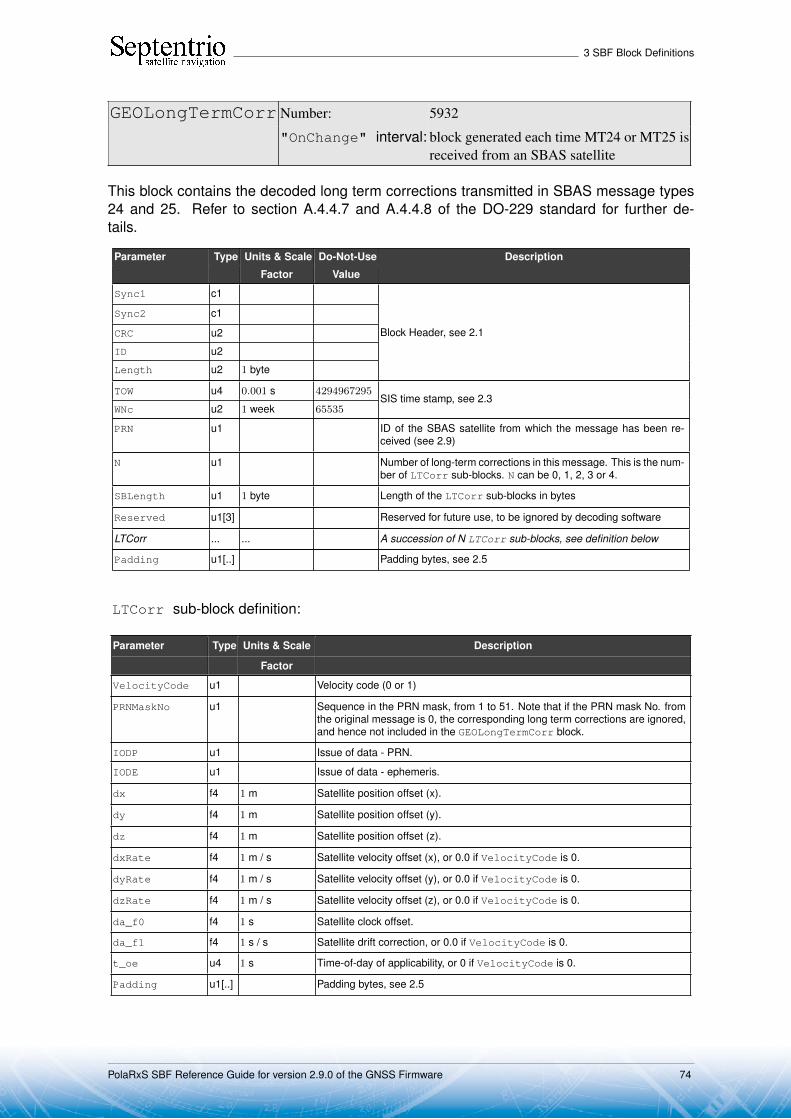
3 SBF Block Definitions
GEOLongTermCorr Number: 5932
"OnChange" interval: block generated each time MT24 or MT25 isreceived from an SBAS satellite
This block contains the decoded long term corrections transmitted in SBAS message types24 and 25. Refer to section A.4.4.7 and A.4.4.8 of the DO-229 standard for further de-tails.
Parameter Type Units & Scale Do-Not-Use Description
Factor Value
Sync1 c1
Block Header, see 2.1
Sync2 c1
CRC u2
ID u2
Length u2 1 byte
TOW u4 0.001 s 4294967295SIS time stamp, see 2.3
WNc u2 1 week 65535
PRN u1 ID of the SBAS satellite from which the message has been re-ceived (see 2.9)
N u1 Number of long-term corrections in this message. This is the num-ber of LTCorr sub-blocks. N can be 0, 1, 2, 3 or 4.
SBLength u1 1 byte Length of the LTCorr sub-blocks in bytes
Reserved u1[3] Reserved for future use, to be ignored by decoding software
LTCorr ... ... A succession of N LTCorr sub-blocks, see definition below
Padding u1[..] Padding bytes, see 2.5
LTCorr sub-block definition:
Parameter Type Units & Scale Description
Factor
VelocityCode u1 Velocity code (0 or 1)
PRNMaskNo u1 Sequence in the PRN mask, from 1 to 51. Note that if the PRN mask No. fromthe original message is 0, the corresponding long term corrections are ignored,and hence not included in the GEOLongTermCorr block.
IODP u1 Issue of data - PRN.
IODE u1 Issue of data - ephemeris.
dx f4 1 m Satellite position offset (x).
dy f4 1 m Satellite position offset (y).
dz f4 1 m Satellite position offset (z).
dxRate f4 1 m / s Satellite velocity offset (x), or 0.0 if VelocityCode is 0.
dyRate f4 1 m / s Satellite velocity offset (y), or 0.0 if VelocityCode is 0.
dzRate f4 1 m / s Satellite velocity offset (z), or 0.0 if VelocityCode is 0.
da_f0 f4 1 s Satellite clock offset.
da_f1 f4 1 s / s Satellite drift correction, or 0.0 if VelocityCode is 0.
t_oe u4 1 s Time-of-day of applicability, or 0 if VelocityCode is 0.
Padding u1[..] Padding bytes, see 2.5
PolaRxS SBF Reference Guide for version 2.9.0 of the GNSS Firmware 74

3 SBF Block Definitions
GEOIonoDelay Number: 5933
"OnChange" interval: block generated each time MT26 is received froman SBAS satellite
This block contains the decoded ionospheric delays transmitted in SBAS message type 26.Refer to section A.4.4.10 of the DO-229 standard for further details.
Parameter Type Units & Scale Do-Not-Use Description
Factor Value
Sync1 c1
Block Header, see 2.1
Sync2 c1
CRC u2
ID u2
Length u2 1 byte
TOW u4 0.001 s 4294967295SIS time stamp, see 2.3
WNc u2 1 week 65535
PRN u1 ID of the SBAS satellite from which the message has been re-ceived (see 2.9)
BandNbr u1 Band number
IODI u1 Issue of data - ionosphere.
N u1 Number of ionospheric delay corrections in this message. This isthe number of IDC sub-blocks. N is always 15.
SBLength u1 1 byte Length of the IDC sub-blocks in bytes.
Reserved u1 Reserved for future use, to be ignored by decoding software
IDC ... ... A succession of N IDC sub-blocks, see definition below
Padding u1[..] Padding bytes, see 2.5
IDC sub-block definition:
Parameter Type Units & Scale Description
Factor
IGPMaskNo u1 Sequence number in the IGP mask (see GEOIGPMask block), from 1 to 201.
GIVEI u1 Grid Ionospheric Vertical Error Indicator, from 0 to 15
Reserved u1[2] Reserved for future use, to be ignored by decoding software
VerticalDelay f4 1 m IGP vertical delay estimate.
Padding u1[..] Padding bytes, see 2.5
PolaRxS SBF Reference Guide for version 2.9.0 of the GNSS Firmware 75

3 SBF Block Definitions
GEOServiceLevel Number: 5917"OnChange" interval: block generated each time MT27 is received
from an SBAS satellite
This block contains a decoded service level message for a geostationary SBAS satelliteas sent in message type 27. Refer to section A.4.4.13 of the DO-229 standard for furtherdetails.
Parameter Type Units & Scale Do-Not-Use Description
Factor Value
Sync1 c1
Block Header, see 2.1
Sync2 c1
CRC u2
ID u2
Length u2 1 byte
TOW u4 0.001 s 4294967295SIS time stamp, see 2.3
WNc u2 1 week 65535
PRN u1 ID of the SBAS satellite from which this service level messagewas received (see 2.9)
Reserved u1 Reserved for future use, to be ignored by decoding software
IODS u1 Issue of Data Service level, ranging from 0 to 7
nrMessages u1 Number of service messages (MT27), from 1 to 8
MessageNR u1 Service message number, from 1 to 8
PriorityCode u1 Priority Code, from 0 to 3
dUDREI_In u1 δUDRE Indicator for users inside the service region, from 0 to 15
dUDREI_Out u1 δUDRE Indicator for users outside the service region, from 0 to15
N u1 Number of Regions in this message. This is the number ofServiceRegion sub-blocks. Ranging from 0 to 7
SBLength u1 1 byte Length of the ServiceRegion sub-blocks in bytes
Regions ... ... A succession of N ServiceRegion sub-blocks, see definitionbelow
Padding u1[..] Padding bytes, see 2.5
ServiceRegion sub-block definition:
Parameter Type Units & Scale Description
Factor
Latitude1 i1 1 degree Coordinate 1 latitude, from -90 to +90
Latitude2 i1 1 degree Coordinate 2 latitude, from -90 to +90
Longitude1 i2 1 degree Coordinate 1 longitude, from -180 to +180
Longitude2 i2 1 degree Coordinate 2 longitude, from -180 to +180
RegionShape u1 Region Shape: 0=triangular, 1=square
Padding u1[..] Padding bytes, see 2.5
PolaRxS SBF Reference Guide for version 2.9.0 of the GNSS Firmware 76

3 SBF Block Definitions
GEOClockEphCovMatrix Number: 5934
"OnChange" interval: block generated each time MT28 isreceived from an SBAS satellite
This block contains the decoded clock-ephemeris covariance Cholesky factor matrix trans-mitted in SBAS message type 28. Refer to section A.4.4.16 of the DO-229 standard forfurther details.
Parameter Type Units & Scale Do-Not-Use Description
Factor Value
Sync1 c1
Block Header, see 2.1
Sync2 c1
CRC u2
ID u2
Length u2 1 byte
TOW u4 0.001 s 4294967295SIS time stamp, see 2.3
WNc u2 1 week 65535
PRN u1
IODP u1 Issue of data - PRN.
N u1 Number of covariance matrices in this message. This is the num-ber of CovMatrix sub-blocks. N can be 1 or 2.
SBLength u1 1 byte Length of the CovMatrix sub-blocks in bytes
Reserved u1[2] Reserved for future use, to be ignored by decoding software
CovMatrix ... ... A succession of N CovMatrix sub-blocks, see definition below
Padding u1[..] Padding bytes, see 2.5
CovMatrix sub-block definition:
Parameter Type Units & Scale Description
Factor
PRNMaskNo u1 Sequence number in the PRN mask, from 1 to 51. Note that if the PRN maskNo. from the original message is 0, the corresponding matrix is ignored, andhence not included in the GEOClockEphCovMatrix block.
Reserved u1[2] Reserved for future use, to be ignored by decoding software
ScaleExp u1 Scale exponent; scale factor ( = 2(scale exponent - 5))
E11 u2 E1,1
E22 u2 E2,2
E33 u2 E3,3
E44 u2 E4,4
E12 i2 E1,2
E13 i2 E1,3
E14 i2 E1,4
E23 i2 E2,3
E24 i2 E2,4
E34 i2 E3,4
Padding u1[..] Padding bytes, see 2.5
PolaRxS SBF Reference Guide for version 2.9.0 of the GNSS Firmware 77
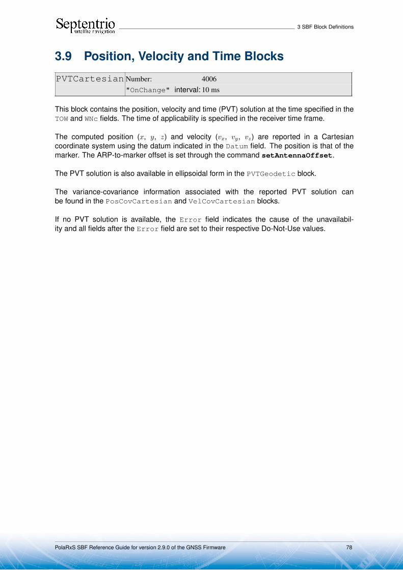
3 SBF Block Definitions
3.9 Position, Velocity and Time Blocks
PVTCartesian Number: 4006"OnChange" interval: 10 ms
This block contains the position, velocity and time (PVT) solution at the time specified in theTOW and WNc fields. The time of applicability is specified in the receiver time frame.
The computed position (x, y, z) and velocity (vx, vy, vz) are reported in a Cartesiancoordinate system using the datum indicated in the Datum field. The position is that of themarker. The ARP-to-marker offset is set through the command setAntennaOffset.
The PVT solution is also available in ellipsoidal form in the PVTGeodetic block.
The variance-covariance information associated with the reported PVT solution canbe found in the PosCovCartesian and VelCovCartesian blocks.
If no PVT solution is available, the Error field indicates the cause of the unavailabil-ity and all fields after the Error field are set to their respective Do-Not-Use values.
PolaRxS SBF Reference Guide for version 2.9.0 of the GNSS Firmware 78

3 SBF Block Definitions
Parameter Type Units & Scale Do-Not-Use Description
Factor Value
Sync1 c1
Block Header, see 2.1
Sync2 c1
CRC u2
ID u2
Length u2 1 byte
TOW u4 0.001 s 4294967295Receiver time stamp, see 2.3
WNc u2 1 week 65535
Mode u1 Bit field indicating the PVT mode, as follows:
Bits 0-3: type of PVT solution:0: No PVT available (the Error field indicates the
cause of the absence of the PVT solution)1: Stand-Alone PVT2: Differential PVT3: Fixed location4: RTK with fixed ambiguities5: RTK with float ambiguities6: SBAS aided PVT7: moving-base RTK with fixed ambiguities8: moving-base RTK with float ambiguities10: Precise Point Positioning (PPP)
Bits 4-5: Reserved
Bit 6: Set if the user has entered the commandsetPVTMode,base,auto and the receiver isstill in the process of determining its fixed position.
Bit 7: 2D/3D flag: set in 2D mode (height assumed constantand not computed).
Error u1 PVT error code. The following values are defined:0: No Error1: Not enough measurements2: Not enough ephemerides available3: DOP too large (larger than 15)4: Sum of squared residuals too large5: No convergence6: Not enough measurements after outlier rejection7: Position output prohibited due to export laws8: Not enough differential corrections available9: Base station coordinates unavailable10: Ambiguities not fixed and user requested to only output RTK-
fixed positions
Note: if this field has a non-zero value, all following fields are setto their Do-Not-Use value.
X f8 1 m −2 · 1010 Marker X coordinate in coordinate frame specified by Datum
Y f8 1 m −2 · 1010 Marker Y coordinate in coordinate frame specified by Datum
Z f8 1 m −2 · 1010 Marker Z coordinate in coordinate frame specified by Datum
Undulation f4 1 m −2 · 1010 Geoid undulation computed from the global geoid model definedin the document ’Technical Characteristics of the NAVSTAR GPS,NATO, June 1991’
Vx f4 1 m / s −2 · 1010 Velocity in the X direction
Vy f4 1 m / s −2 · 1010 Velocity in the Y direction
PolaRxS SBF Reference Guide for version 2.9.0 of the GNSS Firmware 79

3 SBF Block Definitions
Vz f4 1 m / s −2 · 1010 Velocity in the Z direction
COG f4 1 degree −2 · 1010 Course over ground: this is defined as the angle of the vehiclewith respect to the local level North, ranging from 0 to 360, andincreasing towards east. Set to the do-not-use value when thespeed is lower than 0.1m/s.
RxClkBias f8 1 ms −2 · 1010 Receiver clock bias relative to system time reported in theTimeSystem field. To transfer the receiver time to the systemtime, use:tGPS/GST = trx - RxClkBias
RxClkDrift f4 1 ppm −2 · 1010 Receiver clock drift relative to system time (relative frequency er-ror)
TimeSystem u1 255 Time system of which the offset is provided in this sub-block:0: GPS time1: Galileo time3: GLONASS time
Datum u1 255 This field defines in which datum the coordinates are expressed:0: WGS84/ITRS19: Datum equal to that used by the DGNSS/RTK base station30: ETRS89 (ETRF2000 realization)31: NAD83(2011), North American Datum (2011)32: NAD83(PA11), North American Datum, Pacific plate (2011)33: NAD83(MA11), North American Datum, Marianas plate
(2011)34: GDA94(2010), Geocentric Datum of Australia (2010)250: First user-defined datum251: Second user-defined datum
NrSV u1 255 Total number of satellites used in the PVT computation.
WACorrInfo u1 0 Bit field providing information about which wide area correctionshave been applied:
Bit 0: set if orbit and satellite clock correction information isused
Bit 1: set if range correction information is used
Bit 2: set if ionospheric information is used
Bit 3: set if orbit accuracy information is used (UERE/SISA)
Bit 4: set if DO229 Precision Approach mode is active
Bits 5-7: Reserved
ReferenceID u2 65535 This field indicates the reference ID of the differential informationused.In case of DGPS or RTK operation, this field is to be interpretedas the base station identifier. In SBAS operation, this field is to beinterpreted as the PRN of the geostationary satellite used (from120 to 158). If multiple base stations or multiple geostationarysatellites are used the value is set to 65534.
MeanCorrAge u2 0.01 s 65535 In case of DGPS or RTK, this field is the mean age of the differ-ential corrections.In case of SBAS operation, this field is the mean age of the ’fastcorrections’ provided by the SBAS satellites.
SignalInfo u4 0 Bit field indicating the type of GNSS signals having been used inthe PVT computations. If a bit i is set, the signal type having indexi has been used. The signal numbers are listed in section 2.10.Bit 0 (GPS-C/A) is the LSB of SignalInfo.
PolaRxS SBF Reference Guide for version 2.9.0 of the GNSS Firmware 80
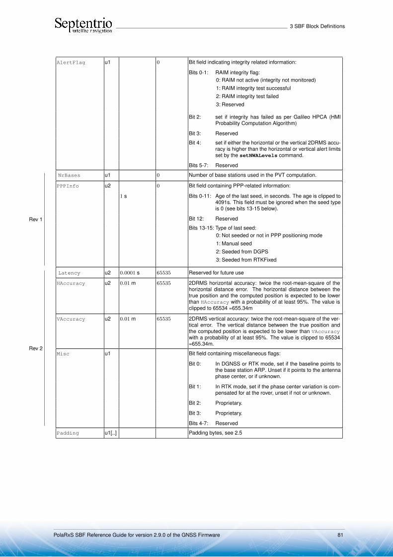
3 SBF Block Definitions
AlertFlag u1 0 Bit field indicating integrity related information:
Bits 0-1: RAIM integrity flag:0: RAIM not active (integrity not monitored)1: RAIM integrity test successful2: RAIM integrity test failed3: Reserved
Bit 2: set if integrity has failed as per Galileo HPCA (HMIProbability Computation Algorithm)
Bit 3: Reserved
Bit 4: set if either the horizontal or the vertical 2DRMS accu-racy is higher than the horizontal or vertical alert limitsset by the setNWALevels command.
Bits 5-7: Reserved
NrBases u1 0 Number of base stations used in the PVT computation.
PPPInfo u2 0 Bit field containing PPP-related information:
1 s Bits 0-11: Age of the last seed, in seconds. The age is clipped to4091s. This field must be ignored when the seed typeis 0 (see bits 13-15 below).
Bit 12: Reserved
Bits 13-15: Type of last seed:0: Not seeded or not in PPP positioning mode1: Manual seed2: Seeded from DGPS3: Seeded from RTKFixed
Rev 1
Latency u2 0.0001 s 65535 Reserved for future use
HAccuracy u2 0.01 m 65535 2DRMS horizontal accuracy: twice the root-mean-square of thehorizontal distance error. The horizontal distance between thetrue position and the computed position is expected to be lowerthan HAccuracy with a probability of at least 95%. The value isclipped to 65534 =655.34m
VAccuracy u2 0.01 m 65535 2DRMS vertical accuracy: twice the root-mean-square of the ver-tical error. The vertical distance between the true position andthe computed position is expected to be lower than VAccuracywith a probability of at least 95%. The value is clipped to 65534=655.34m.
Misc u1 Bit field containing miscellaneous flags:
Bit 0: In DGNSS or RTK mode, set if the baseline points tothe base station ARP. Unset if it points to the antennaphase center, or if unknown.
Bit 1: In RTK mode, set if the phase center variation is com-pensated for at the rover, unset if not or unknown.
Bit 2: Proprietary.
Bit 3: Proprietary.
Bits 4-7: Reserved
Rev 2
Padding u1[..] Padding bytes, see 2.5
PolaRxS SBF Reference Guide for version 2.9.0 of the GNSS Firmware 81
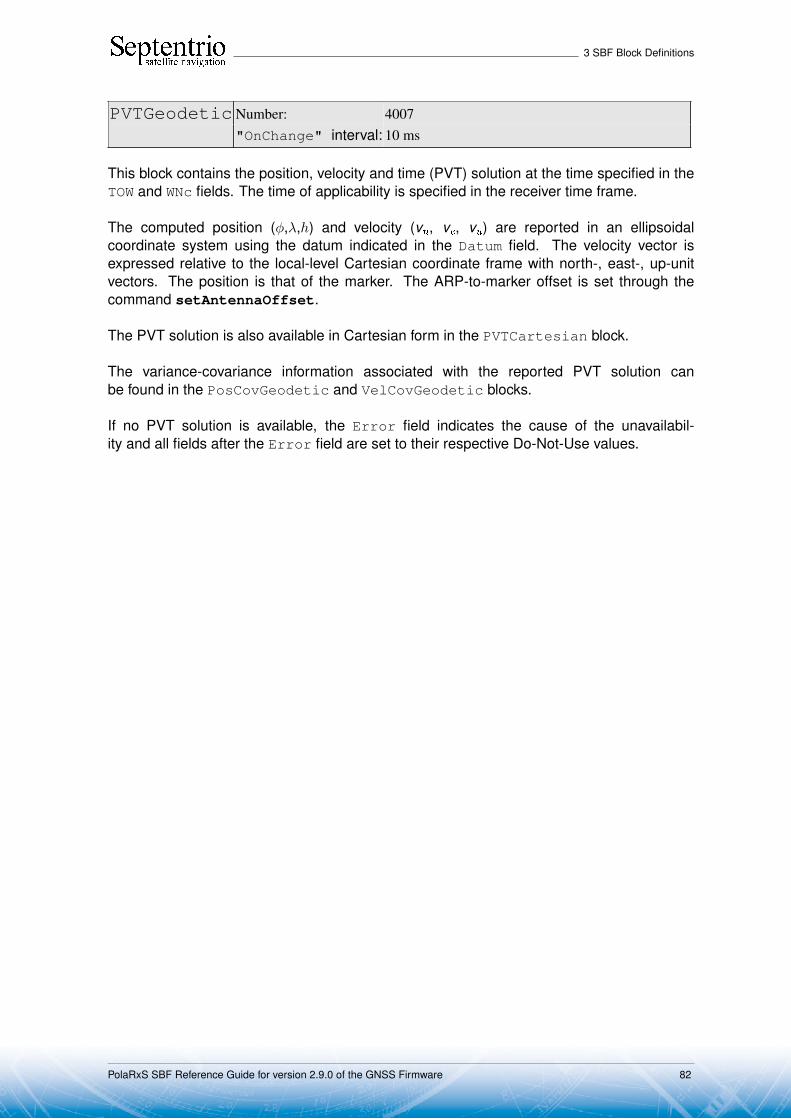
3 SBF Block Definitions
PVTGeodetic Number: 4007"OnChange" interval: 10 ms
This block contains the position, velocity and time (PVT) solution at the time specified in theTOW and WNc fields. The time of applicability is specified in the receiver time frame.
The computed position (φ,λ,h) and velocity (vn, ve, vu) are reported in an ellipsoidalcoordinate system using the datum indicated in the Datum field. The velocity vector isexpressed relative to the local-level Cartesian coordinate frame with north-, east-, up-unitvectors. The position is that of the marker. The ARP-to-marker offset is set through thecommand setAntennaOffset.
The PVT solution is also available in Cartesian form in the PVTCartesian block.
The variance-covariance information associated with the reported PVT solution canbe found in the PosCovGeodetic and VelCovGeodetic blocks.
If no PVT solution is available, the Error field indicates the cause of the unavailabil-ity and all fields after the Error field are set to their respective Do-Not-Use values.
PolaRxS SBF Reference Guide for version 2.9.0 of the GNSS Firmware 82

3 SBF Block Definitions
Parameter Type Units & Scale Do-Not-Use Description
Factor Value
Sync1 c1
Block Header, see 2.1
Sync2 c1
CRC u2
ID u2
Length u2 1 byte
TOW u4 0.001 s 4294967295Receiver time stamp, see 2.3
WNc u2 1 week 65535
Mode u1 Bit field indicating the PVT mode, as follows:
Bits 0-3: type of PVT solution:0: No PVT available (the Error field indicates the
cause of the absence of the PVT solution)1: Stand-Alone PVT2: Differential PVT3: Fixed location4: RTK with fixed ambiguities5: RTK with float ambiguities6: SBAS aided PVT7: moving-base RTK with fixed ambiguities8: moving-base RTK with float ambiguities10: Precise Point Positioning (PPP)
Bits 4-5: Reserved
Bit 6: Set if the user has entered the commandsetPVTMode,base,auto and the receiver isstill in the process of determining its fixed position.
Bit 7: 2D/3D flag: set in 2D mode (height assumed constantand not computed).
Error u1 PVT error code. The following values are defined:0: No Error1: Not enough measurements2: Not enough ephemerides available3: DOP too large (larger than 15)4: Sum of squared residuals too large5: No convergence6: Not enough measurements after outlier rejection7: Position output prohibited due to export laws8: Not enough differential corrections available9: Base station coordinates unavailable10: Ambiguities not fixed and user requested to only output RTK-
fixed positions
Note: if this field has a non-zero value, all following fields are setto their Do-Not-Use value.
Latitude f8 1 rad −2 · 1010 Marker latitude, from −π/2 to +π/2, positive North of Equator
Longitude f8 1 rad −2 · 1010 Marker longitude, from −π to +π, positive East of Greenwich
Height f8 1 m −2 · 1010 Marker ellipsoidal height (with respect to the ellipsoid specified byDatum)
Undulation f4 1 m −2 · 1010 Geoid undulation computed from the global geoid model definedin the document ’Technical Characteristics of the NAVSTAR GPS,NATO, June 1991’
Vn f4 1 m / s −2 · 1010 Velocity in the North direction
Ve f4 1 m / s −2 · 1010 Velocity in the East direction
PolaRxS SBF Reference Guide for version 2.9.0 of the GNSS Firmware 83
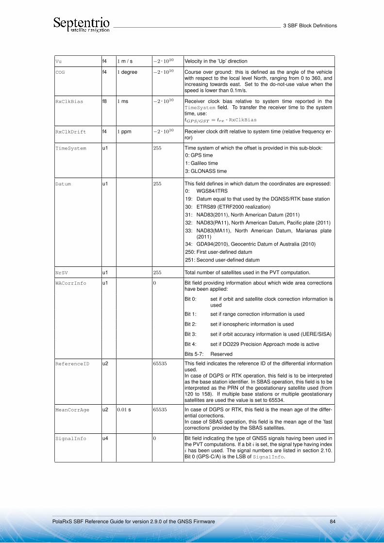
3 SBF Block Definitions
Vu f4 1 m / s −2 · 1010 Velocity in the ’Up’ direction
COG f4 1 degree −2 · 1010 Course over ground: this is defined as the angle of the vehiclewith respect to the local level North, ranging from 0 to 360, andincreasing towards east. Set to the do-not-use value when thespeed is lower than 0.1m/s.
RxClkBias f8 1 ms −2 · 1010 Receiver clock bias relative to system time reported in theTimeSystem field. To transfer the receiver time to the systemtime, use:tGPS/GST = trx - RxClkBias
RxClkDrift f4 1 ppm −2 · 1010 Receiver clock drift relative to system time (relative frequency er-ror)
TimeSystem u1 255 Time system of which the offset is provided in this sub-block:0: GPS time1: Galileo time3: GLONASS time
Datum u1 255 This field defines in which datum the coordinates are expressed:0: WGS84/ITRS19: Datum equal to that used by the DGNSS/RTK base station30: ETRS89 (ETRF2000 realization)31: NAD83(2011), North American Datum (2011)32: NAD83(PA11), North American Datum, Pacific plate (2011)33: NAD83(MA11), North American Datum, Marianas plate
(2011)34: GDA94(2010), Geocentric Datum of Australia (2010)250: First user-defined datum251: Second user-defined datum
NrSV u1 255 Total number of satellites used in the PVT computation.
WACorrInfo u1 0 Bit field providing information about which wide area correctionshave been applied:
Bit 0: set if orbit and satellite clock correction information isused
Bit 1: set if range correction information is used
Bit 2: set if ionospheric information is used
Bit 3: set if orbit accuracy information is used (UERE/SISA)
Bit 4: set if DO229 Precision Approach mode is active
Bits 5-7: Reserved
ReferenceID u2 65535 This field indicates the reference ID of the differential informationused.In case of DGPS or RTK operation, this field is to be interpretedas the base station identifier. In SBAS operation, this field is to beinterpreted as the PRN of the geostationary satellite used (from120 to 158). If multiple base stations or multiple geostationarysatellites are used the value is set to 65534.
MeanCorrAge u2 0.01 s 65535 In case of DGPS or RTK, this field is the mean age of the differ-ential corrections.In case of SBAS operation, this field is the mean age of the ’fastcorrections’ provided by the SBAS satellites.
SignalInfo u4 0 Bit field indicating the type of GNSS signals having been used inthe PVT computations. If a bit i is set, the signal type having indexi has been used. The signal numbers are listed in section 2.10.Bit 0 (GPS-C/A) is the LSB of SignalInfo.
PolaRxS SBF Reference Guide for version 2.9.0 of the GNSS Firmware 84

3 SBF Block Definitions
AlertFlag u1 0 Bit field indicating integrity related information:
Bits 0-1: RAIM integrity flag:0: RAIM not active (integrity not monitored)1: RAIM integrity test successful2: RAIM integrity test failed3: Reserved
Bit 2: set if integrity has failed as per Galileo HPCA (HMIProbability Computation Algorithm)
Bit 3: Reserved
Bit 4: set if either the horizontal or the vertical 2DRMS accu-racy is higher than the horizontal or vertical alert limitsset by the setNWALevels command.
Bits 5-7: Reserved
NrBases u1 0 Number of base stations used in the PVT computation.
PPPInfo u2 0 Bit field containing PPP-related information:
1 s Bits 0-11: Age of the last seed, in seconds. The age is clipped to4091s. This field must be ignored when the seed typeis 0 (see bits 13-15 below).
Bit 12: Reserved
Bits 13-15: Type of last seed:0: Not seeded or not in PPP positioning mode1: Manual seed2: Seeded from DGPS3: Seeded from RTKFixed
Rev 1
Latency u2 0.0001 s 65535 Reserved for future use
HAccuracy u2 0.01 m 65535 2DRMS horizontal accuracy: twice the root-mean-square of thehorizontal distance error. The horizontal distance between thetrue position and the computed position is expected to be lowerthan HAccuracy with a probability of at least 95%. The value isclipped to 65534 =655.34m
VAccuracy u2 0.01 m 65535 2DRMS vertical accuracy: twice the root-mean-square of the ver-tical error. The vertical distance between the true position andthe computed position is expected to be lower than VAccuracywith a probability of at least 95%. The value is clipped to 65534=655.34m.
Misc u1 Bit field containing miscellaneous flags:
Bit 0: In DGNSS or RTK mode, set if the baseline points tothe base station ARP. Unset if it points to the antennaphase center, or if unknown.
Bit 1: In RTK mode, set if the phase center variation is com-pensated for at the rover, unset if not or unknown.
Bit 2: Proprietary.
Bit 3: Proprietary.
Bits 4-7: Reserved
Rev 2
Padding u1[..] Padding bytes, see 2.5
PolaRxS SBF Reference Guide for version 2.9.0 of the GNSS Firmware 85

3 SBF Block Definitions
PosCovCartesian Number: 5905"OnChange" interval: 10 ms
This block contains the elements of the symmetric variance-covariance matrix of the positionexpressed relative to the Cartesian axes of the coordinate system datum requested by theuser:
σ2x σxy σxz σxb
σyx σ2y σyz σyb
σzx σzy σ2z σzb
σbx σby σbz σ2b
This variance-covariance matrix contains an indication of the accuracy of the esti-mated parameters (see diagonal elements) and the correlation between these estimates(see off-diagonal elements). Note that the variances and covariances are estimated: theyare not necessarily indicative of the actual scatter of the position estimates at a given site.
The position variance results from the propagation of all pseudorange variances usingthe observation geometry. The receiver implements a stochastic error model for individualmeasurements, based on parameters such as the C/N0, the satellite elevation, the pseudor-ange type, the URA of the broadcast ephemeris and the ionospheric model.
If the ellipsoidal height is not estimated (2D-mode), all components of the variance-covariance matrix are undefined and set to their Do-Not-Use value.
PolaRxS SBF Reference Guide for version 2.9.0 of the GNSS Firmware 86

3 SBF Block Definitions
Parameter Type Units & Scale Do-Not-Use Description
Factor Value
Sync1 c1
Block Header, see 2.1
Sync2 c1
CRC u2
ID u2
Length u2 1 byte
TOW u4 0.001 s 4294967295Receiver time stamp, see 2.3
WNc u2 1 week 65535
Mode u1 Bit field indicating the PVT mode, as follows:
Bits 0-3: type of PVT solution:0: No PVT available (the Error field indicates the
cause of the absence of the PVT solution)1: Stand-Alone PVT2: Differential PVT3: Fixed location4: RTK with fixed ambiguities5: RTK with float ambiguities6: SBAS aided PVT7: moving-base RTK with fixed ambiguities8: moving-base RTK with float ambiguities10: Precise Point Positioning (PPP)
Bits 4-5: Reserved
Bit 6: Set if the user has entered the commandsetPVTMode,base,auto and the receiver is stillin the process of determining its fixed position.
Bit 7: 2D/3D flag: set in 2D mode (height assumed constantand not computed).
Error u1 PVT error code. The following values are defined:0: No Error1: Not enough measurements2: Not enough ephemerides available3: DOP too large (larger than 15)4: Sum of squared residuals too large5: No convergence6: Not enough measurements after outlier rejection7: Position output prohibited due to export laws8: Not enough differential corrections available9: Base station coordinates unavailable10: Ambiguities not fixed and user requested to only output RTK-
fixed positions
Note: if this field has a non-zero value, all following fields are setto their Do-Not-Use value.
Cov_xx f4 1 m2 −2 · 1010 Variance of the x estimate
Cov_yy f4 1 m2 −2 · 1010 Variance of the y estimate
Cov_zz f4 1 m2 −2 · 1010 Variance of the z estimate
Cov_bb f4 1 m2 −2 · 1010 Variance of the clock bias estimate
Cov_xy f4 1 m2 −2 · 1010 Covariance between the x and y estimates
Cov_xz f4 1 m2 −2 · 1010 Covariance between the x and z estimates
Cov_xb f4 1 m2 −2 · 1010 Covariance between the x and clock bias estimates
PolaRxS SBF Reference Guide for version 2.9.0 of the GNSS Firmware 87

3 SBF Block Definitions
Cov_yz f4 1 m2 −2 · 1010 Covariance between the y and z estimates
Cov_yb f4 1 m2 −2 · 1010 Covariance between the y and clock bias estimates
Cov_zb f4 1 m2 −2 · 1010 Covariance between the z and clock bias estimates
Padding u1[..] Padding bytes, see 2.5
PolaRxS SBF Reference Guide for version 2.9.0 of the GNSS Firmware 88

3 SBF Block Definitions
PosCovGeodetic Number: 5906"OnChange" interval: 10 ms
This block contains the elements of the symmetric variance-covariance matrix of the positionexpressed in the geodetic coordinates in the datum requested by the user:
σ2φ σφλ σφh σφb
σλφ σ2λ σλh σλb
σhφ σhλ σ2h σhb
σbφ σbλ σbh σ2b
Please refer to the PosCovCartesian block description for a general explanation of thecontents.
Note that the units of measure for all the variances and covariances, for height aswell as for latitude and longitude, are m2 for ease of interpretation.
If the ellipsoidal height is not estimated (2D-mode), all height related components ofthe variance-covariance matrix are undefined and set to their Do-Not-Use value.
PolaRxS SBF Reference Guide for version 2.9.0 of the GNSS Firmware 89

3 SBF Block Definitions
Parameter Type Units & Scale Do-Not-Use Description
Factor Value
Sync1 c1
Block Header, see 2.1
Sync2 c1
CRC u2
ID u2
Length u2 1 byte
TOW u4 0.001 s 4294967295Receiver time stamp, see 2.3
WNc u2 1 week 65535
Mode u1 Bit field indicating the PVT mode, as follows:
Bits 0-3: type of PVT solution:0: No PVT available (the Error field indicates the
cause of the absence of the PVT solution)1: Stand-Alone PVT2: Differential PVT3: Fixed location4: RTK with fixed ambiguities5: RTK with float ambiguities6: SBAS aided PVT7: moving-base RTK with fixed ambiguities8: moving-base RTK with float ambiguities10: Precise Point Positioning (PPP)
Bits 4-5: Reserved
Bit 6: Set if the user has entered the commandsetPVTMode,base,auto and the receiver is stillin the process of determining its fixed position.
Bit 7: 2D/3D flag: set in 2D mode (height assumed constantand not computed).
Error u1 PVT error code. The following values are defined:0: No Error1: Not enough measurements2: Not enough ephemerides available3: DOP too large (larger than 15)4: Sum of squared residuals too large5: No convergence6: Not enough measurements after outlier rejection7: Position output prohibited due to export laws8: Not enough differential corrections available9: Base station coordinates unavailable10: Ambiguities not fixed and user requested to only output RTK-
fixed positions
Note: if this field has a non-zero value, all following fields are setto their Do-Not-Use value.
Cov_latlat f4 1 m2 −2 · 1010 Variance of the latitude estimate
Cov_lonlon f4 1 m2 −2 · 1010 Variance of the longitude estimate
Cov_hgthgt f4 1 m2 −2 · 1010 Variance of the height estimate
Cov_bb f4 1 m2 −2 · 1010 Variance of the clock-bias estimate
Cov_latlon f4 1 m2 −2 · 1010 Covariance between the latitude and longitude estimates
Cov_lathgt f4 1 m2 −2 · 1010 Covariance between the latitude and height estimates
Cov_latb f4 1 m2 −2 · 1010 Covariance between the latitude and clock-bias estimates
PolaRxS SBF Reference Guide for version 2.9.0 of the GNSS Firmware 90
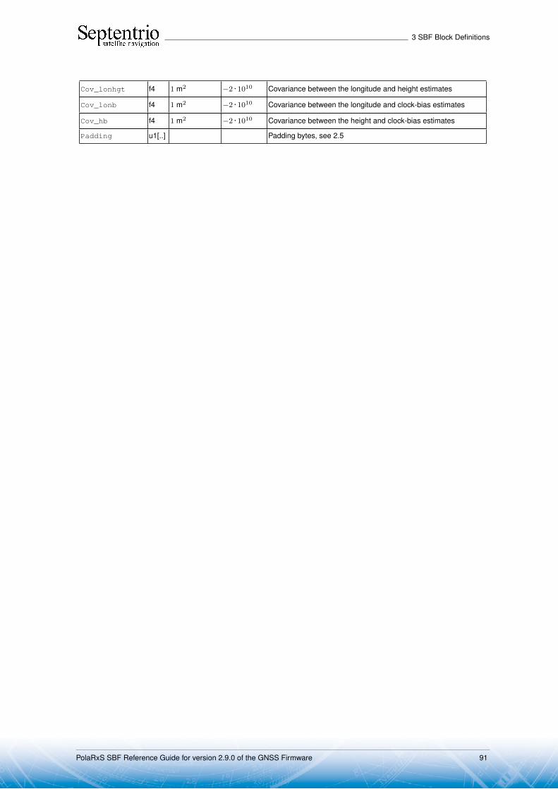
3 SBF Block Definitions
Cov_lonhgt f4 1 m2 −2 · 1010 Covariance between the longitude and height estimates
Cov_lonb f4 1 m2 −2 · 1010 Covariance between the longitude and clock-bias estimates
Cov_hb f4 1 m2 −2 · 1010 Covariance between the height and clock-bias estimates
Padding u1[..] Padding bytes, see 2.5
PolaRxS SBF Reference Guide for version 2.9.0 of the GNSS Firmware 91
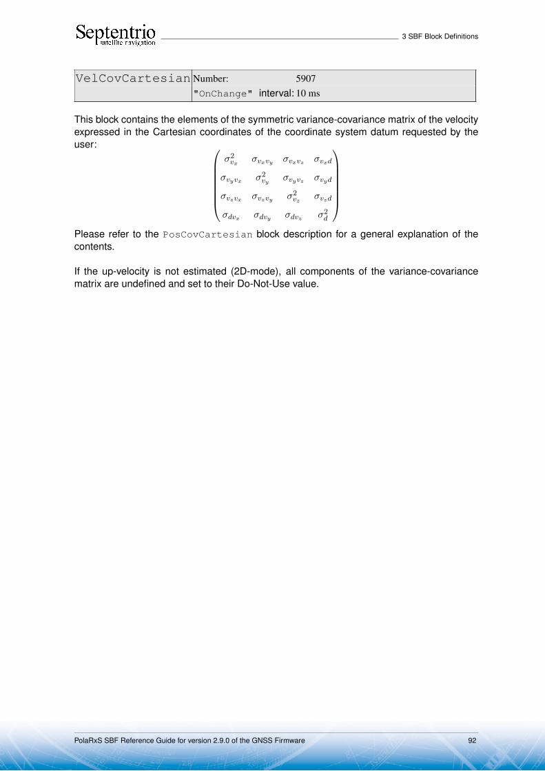
3 SBF Block Definitions
VelCovCartesian Number: 5907"OnChange" interval: 10 ms
This block contains the elements of the symmetric variance-covariance matrix of the velocityexpressed in the Cartesian coordinates of the coordinate system datum requested by theuser:
σ2vx σvxvy σvxvz σvxd
σvyvx σ2vy σvyvz σvyd
σvzvx σvzvy σ2vz σvzd
σdvx σdvy σdvz σ2d
Please refer to the PosCovCartesian block description for a general explanation of thecontents.
If the up-velocity is not estimated (2D-mode), all components of the variance-covariancematrix are undefined and set to their Do-Not-Use value.
PolaRxS SBF Reference Guide for version 2.9.0 of the GNSS Firmware 92

3 SBF Block Definitions
Parameter Type Units & Scale Do-Not-Use Description
Factor Value
Sync1 c1
Block Header, see 2.1
Sync2 c1
CRC u2
ID u2
Length u2 1 byte
TOW u4 0.001 s 4294967295Receiver time stamp, see 2.3
WNc u2 1 week 65535
Mode u1 Bit field indicating the PVT mode, as follows:
Bits 0-3: type of PVT solution:0: No PVT available (the Error field indicates the
cause of the absence of the PVT solution)1: Stand-Alone PVT2: Differential PVT3: Fixed location4: RTK with fixed ambiguities5: RTK with float ambiguities6: SBAS aided PVT7: moving-base RTK with fixed ambiguities8: moving-base RTK with float ambiguities10: Precise Point Positioning (PPP)
Bits 4-5: Reserved
Bit 6: Set if the user has entered the commandsetPVTMode,base,auto and the receiver is stillin the process of determining its fixed position.
Bit 7: 2D/3D flag: set in 2D mode (height assumed constantand not computed).
Error u1 PVT error code. The following values are defined:0: No Error1: Not enough measurements2: Not enough ephemerides available3: DOP too large (larger than 15)4: Sum of squared residuals too large5: No convergence6: Not enough measurements after outlier rejection7: Position output prohibited due to export laws8: Not enough differential corrections available9: Base station coordinates unavailable10: Ambiguities not fixed and user requested to only output RTK-
fixed positions
Note: if this field has a non-zero value, all following fields are setto their Do-Not-Use value.
Cov_VxVx f4 1 m2 / s2 −2 · 1010 Variance of the x-velocity estimate
Cov_VyVy f4 1 m2 / s2 −2 · 1010 Variance of the y-velocity estimate
Cov_VzVz f4 1 m2 / s2 −2 · 1010 Variance of the z-velocity estimate
Cov_DtDt f4 1 m2 / s2 −2 · 1010 Variance of the clock drift estimate
Cov_VxVy f4 1 m2 / s2 −2 · 1010 Covariance between the x- and y-velocity estimates
Cov_VxVz f4 1 m2 / s2 −2 · 1010 Covariance between the x- and z-velocity estimates
Cov_VxDt f4 1 m2 / s2 −2 · 1010 Covariance between the x-velocity and the clock drift estimates
PolaRxS SBF Reference Guide for version 2.9.0 of the GNSS Firmware 93
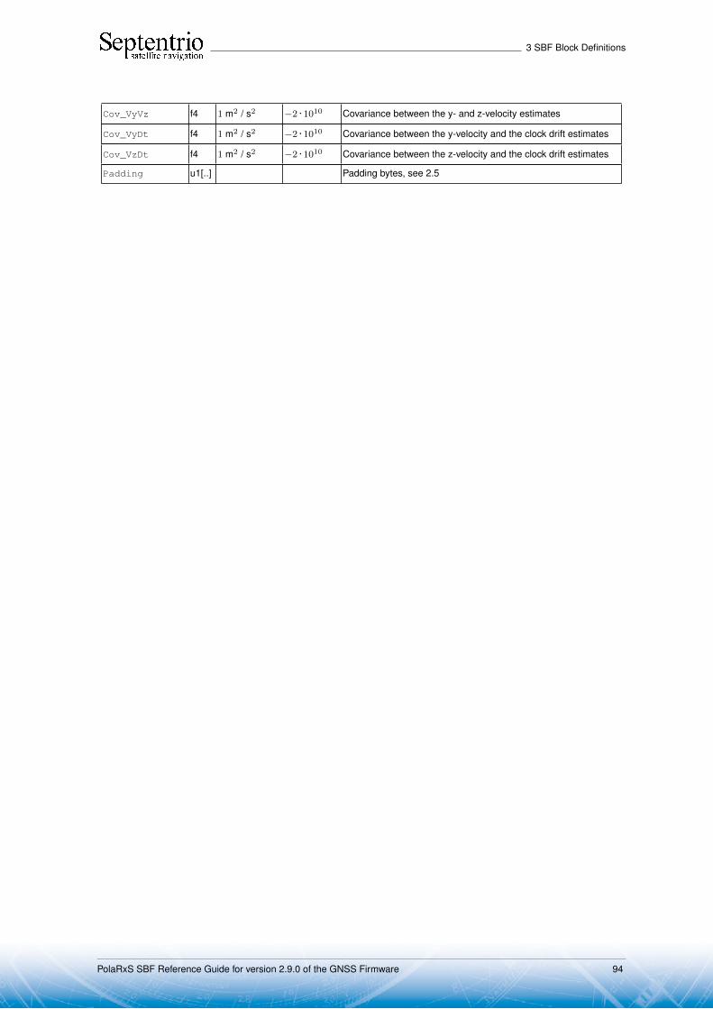
3 SBF Block Definitions
Cov_VyVz f4 1 m2 / s2 −2 · 1010 Covariance between the y- and z-velocity estimates
Cov_VyDt f4 1 m2 / s2 −2 · 1010 Covariance between the y-velocity and the clock drift estimates
Cov_VzDt f4 1 m2 / s2 −2 · 1010 Covariance between the z-velocity and the clock drift estimates
Padding u1[..] Padding bytes, see 2.5
PolaRxS SBF Reference Guide for version 2.9.0 of the GNSS Firmware 94
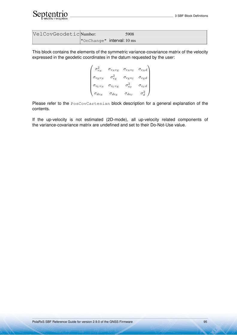
3 SBF Block Definitions
VelCovGeodetic Number: 5908"OnChange" interval: 10 ms
This block contains the elements of the symmetric variance-covariance matrix of the velocityexpressed in the geodetic coordinates in the datum requested by the user:
σ2vN
σvNvE σvNvU σvNd
σvEvN σ2vE
σvEvU σvEd
σvUvN σvUvE σ2vU
σvUd
σdvN σdvE σdvU σ2d
Please refer to the PosCovCartesian block description for a general explanation of thecontents.
If the up-velocity is not estimated (2D-mode), all up-velocity related components ofthe variance-covariance matrix are undefined and set to their Do-Not-Use value.
PolaRxS SBF Reference Guide for version 2.9.0 of the GNSS Firmware 95

3 SBF Block Definitions
Parameter Type Units & Scale Do-Not-Use Description
Factor Value
Sync1 c1
Block Header, see 2.1
Sync2 c1
CRC u2
ID u2
Length u2 1 byte
TOW u4 0.001 s 4294967295Receiver time stamp, see 2.3
WNc u2 1 week 65535
Mode u1 Bit field indicating the PVT mode, as follows:
Bits 0-3: type of PVT solution:0: No PVT available (the Error field indicates the
cause of the absence of the PVT solution)1: Stand-Alone PVT2: Differential PVT3: Fixed location4: RTK with fixed ambiguities5: RTK with float ambiguities6: SBAS aided PVT7: moving-base RTK with fixed ambiguities8: moving-base RTK with float ambiguities10: Precise Point Positioning (PPP)
Bits 4-5: Reserved
Bit 6: Set if the user has entered the commandsetPVTMode,base,auto and the receiver is stillin the process of determining its fixed position.
Bit 7: 2D/3D flag: set in 2D mode (height assumed constantand not computed).
Error u1 PVT error code. The following values are defined:0: No Error1: Not enough measurements2: Not enough ephemerides available3: DOP too large (larger than 15)4: Sum of squared residuals too large5: No convergence6: Not enough measurements after outlier rejection7: Position output prohibited due to export laws8: Not enough differential corrections available9: Base station coordinates unavailable10: Ambiguities not fixed and user requested to only output RTK-
fixed positions
Note: if this field has a non-zero value, all following fields are setto their Do-Not-Use value.
Cov_VnVn f4 1 m2 / s2 −2 · 1010 Variance of the north-velocity estimate
Cov_VeVe f4 1 m2 / s2 −2 · 1010 Variance of the east-velocity estimate
Cov_VuVu f4 1 m2 / s2 −2 · 1010 Variance of the up-velocity estimate
Cov_DtDt f4 1 m2 / s2 −2 · 1010 Variance of the clock drift estimate
Cov_VnVe f4 1 m2 / s2 −2 · 1010 Covariance between the north- and east-velocity estimates
Cov_VnVu f4 1 m2 / s2 −2 · 1010 Covariance between the north- and up-velocity estimates
Cov_VnDt f4 1 m2 / s2 −2 · 1010 Covariance between the north-velocity and clock drift estimates
PolaRxS SBF Reference Guide for version 2.9.0 of the GNSS Firmware 96

3 SBF Block Definitions
Cov_VeVu f4 1 m2 / s2 −2 · 1010 Covariance between the east- and up-velocity estimates
Cov_VeDt f4 1 m2 / s2 −2 · 1010 Covariance between the east-velocity and clock drift estimates
Cov_VuDt f4 1 m2 / s2 −2 · 1010 Covariance between the up-velocity and clock drift estimates
Padding u1[..] Padding bytes, see 2.5
PolaRxS SBF Reference Guide for version 2.9.0 of the GNSS Firmware 97

3 SBF Block Definitions
DOP Number: 4001"OnChange" interval: 10 ms
This block contains both Dilution of Precision (DOP) values and SBAS protection levels. TheDOP values result from a trace of the unit position variance-covariance matrices:
Position Dilution of Precision: PDOP =√
Qxx + Qyy + Qzz
Time Dilution of Precision: TDOP =√
Qbb
Horizontal Dilution of Precision: HDOP =√
Qλλ + Qφφ
Vertical Dilution of Precision: V DOP =√
Qhh
In these equations, the matrix Q is the inverse of the unweighted normal matrix used for thecomputation of the position. The normal matrix equals the product of the geometry matrix Awith its transpose (AtA). The term "unweighted" implies that the DOP factor only addressesthe effect of the geometric factors on the quality of the position.
The DOP values can be used to interpret the current constellation geometry. This isan important parameter for the quality of the position fix: the DOP parameter is thepropagation factor of the pseudorange variance. For example, if an error of 5 m is presentin the pseudorange, it will propagate into the horizontal plane with a factor expressed by theHDOP. Hence a low DOP value indicates that the satellites used for the position fix resultin a low multiplication of the systematic ranging errors. A value of six (6) for the PDOP isgenerally considered as the maximum value allowed for an acceptable position computation.
The horizontal and vertical protection levels (HPL and VPL) indicate the integrity ofthe computed horizontal and vertical position components as per the DO 229 specification.In SBAS-aided PVT mode (see the Mode field of the PVTCartesian SBF block), HPL andVPL are based upon the error estimates provided by SBAS. Otherwise they are based uponinternal position-mode dependent error estimates.
Parameter Type Units & Scale Do-Not-Use Description
Factor Value
Sync1 c1
Block Header, see 2.1
Sync2 c1
CRC u2
ID u2
Length u2 1 byte
TOW u4 0.001 s 4294967295Receiver time stamp, see 2.3
WNc u2 1 week 65535
NrSV u1 0 Total number of satellites used in the DOP computation, or 0 if theDOP information is not available (in that case, the xDOP fields areall set to 0)
Reserved u1 Reserved for future use, to be ignored by decoding software
PDOP u2 0.01 0 If 0, PDOP not available, otherwise divide by 100 to obtain PDOP.
TDOP u2 0.01 0 If 0, TDOP not available, otherwise divide by 100 to obtain TDOP.
HDOP u2 0.01 0 If 0, HDOP not available, otherwise divide by 100 to obtain HDOP.
VDOP u2 0.01 0 If 0, VDOP not available, otherwise divide by 100 to obtain VDOP.
HPL f4 1 m −2 · 1010 Horizontal Protection Level (see the DO 229 standard).
VPL f4 1 m −2 · 1010 Vertical Protection Level (see the DO 229 standard).
PolaRxS SBF Reference Guide for version 2.9.0 of the GNSS Firmware 98

3 SBF Block Definitions
Padding u1[..] Padding bytes, see 2.5
PolaRxS SBF Reference Guide for version 2.9.0 of the GNSS Firmware 99

3 SBF Block Definitions
PosCart Number: 4044"OnChange" interval: 10 ms
This block contains the absolute and relative (relative to the nearest base station) positionat the time specified in the TOW and WNc fields. The time of applicability is specified in thereceiver time frame.
The absolute position (X, Y, Z) is reported in a Cartesian coordinate system using thedatum indicated in the Datum field. The position is that of the marker. The ARP-to-markeroffset is set through the command setAntennaOffset.
For highest accuracy, the receiver tries to compute the baseline (Base2RoverX,Base2RoverY, Base2RoverZ) from rover ARP to base ARP. See the description ofthe BaseVectorCart block for details.
Accurate ARP-to-ARP baseline is guaranteed only if both bits 0 and 1 of the Miscfield are set. Otherwise, centimeter-level offsets may arise because the receiver cannotmake the distinction between phase center and ARP positions. See the Firmware UserManual for a discussion on the phase center and ARP positions.
This block also contains the variance-covariance information and DOP factors associ-ated with the position.
PolaRxS SBF Reference Guide for version 2.9.0 of the GNSS Firmware 100

3 SBF Block Definitions
Parameter Type Units & Scale Do-Not-Use Description
Factor Value
Sync1 c1
Block Header, see 2.1
Sync2 c1
CRC u2
ID u2
Length u2 1 byte
TOW u4 0.001 s 4294967295Receiver time stamp, see 2.3
WNc u2 1 week 65535
Mode u1 Bit field indicating the PVT mode, as follows:
Bits 0-3: type of PVT solution:0: No PVT available (the Error field indicates the
cause of the absence of the PVT solution)1: Stand-Alone PVT2: Differential PVT3: Fixed location4: RTK with fixed ambiguities5: RTK with float ambiguities6: SBAS aided PVT7: moving-base RTK with fixed ambiguities8: moving-base RTK with float ambiguities10: Precise Point Positioning (PPP)
Bits 4-5: Reserved
Bit 6: Set if the user has entered the commandsetPVTMode,base,auto and the receiver is stillin the process of determining its fixed position.
Bit 7: 2D/3D flag: set in 2D mode (height assumed constantand not computed).
Error u1 PVT error code. The following values are defined:0: No Error1: Not enough measurements2: Not enough ephemerides available3: DOP too large (larger than 15)4: Sum of squared residuals too large5: No convergence6: Not enough measurements after outlier rejection7: Position output prohibited due to export laws8: Not enough differential corrections available9: Base station coordinates unavailable10: Ambiguities not fixed and user requested to only output RTK-
fixed positions
Note: if this field has a non-zero value, all following fields are setto their Do-Not-Use value.
X f8 1 m −2 · 1010 Marker X coordinate in coordinate frame specified by Datum
Y f8 1 m −2 · 1010 Marker Y coordinate in coordinate frame specified by Datum
Z f8 1 m −2 · 1010 Marker Z coordinate in coordinate frame specified by Datum
Base2RoverX f8 1 m −2 · 1010 X baseline component (from base to rover)
Base2RoverY f8 1 m −2 · 1010 Y baseline component (from base to rover)
Base2RoverZ f8 1 m −2 · 1010 Z baseline component (from base to rover)
Cov_xx f4 1 m2 −2 · 1010 Variance of the x estimate
PolaRxS SBF Reference Guide for version 2.9.0 of the GNSS Firmware 101

3 SBF Block Definitions
Cov_yy f4 1 m2 −2 · 1010 Variance of the y estimate
Cov_zz f4 1 m2 −2 · 1010 Variance of the z estimate
Cov_xy f4 1 m2 −2 · 1010 Covariance between the x and y estimates
Cov_xz f4 1 m2 −2 · 1010 Covariance between the x and z estimates
Cov_yz f4 1 m2 −2 · 1010 Covariance between the y and z estimates
PDOP u2 0.01 0 If 0, PDOP not available, otherwise divide by 100 to obtain PDOP.
HDOP u2 0.01 0 If 0, HDOP not available, otherwise divide by 100 to obtain HDOP.
VDOP u2 0.01 0 If 0, VDOP not available, otherwise divide by 100 to obtain VDOP.
Misc u1 Bit field containing miscellaneous flags:
Bit 0: In DGNSS or RTK mode, set if the baseline points to thebase station ARP. Unset if it points to the antenna phasecenter, or if unknown.
Bit 1: In RTK mode, set if the phase center variation is com-pensated for at the rover, unset if not or unknown.
Bit 2: Proprietary.
Bit 3: Proprietary.
Bits 4-7: Reserved
Reserved u1 Reserved for future use.
AlertFlag u1 0 Bit field indicating integrity related information:
Bits 0-1: RAIM integrity flag:0: RAIM not active (integrity not monitored)1: RAIM integrity test successful2: RAIM integrity test failed3: Reserved
Bit 2: set if integrity has failed as per Galileo HPCA (HMI Prob-ability Computation Algorithm)
Bit 3: Reserved
Bit 4: set if either the horizontal or the vertical 2DRMS accu-racy is higher than the horizontal or vertical alert limitsset by the setNWALevels command.
Bits 5-7: Reserved
Datum u1 255 This field defines in which datum the coordinates are expressed:0: WGS84/ITRS19: Datum equal to that used by the DGNSS/RTK base station30: ETRS89 (ETRF2000 realization)31: NAD83(2011), North American Datum (2011)32: NAD83(PA11), North American Datum, Pacific plate (2011)33: NAD83(MA11), North American Datum, Marianas plate
(2011)34: GDA94(2010), Geocentric Datum of Australia (2010)250: First user-defined datum251: Second user-defined datum
NrSV u1 255 Total number of satellites used in the PVT computation.
PolaRxS SBF Reference Guide for version 2.9.0 of the GNSS Firmware 102
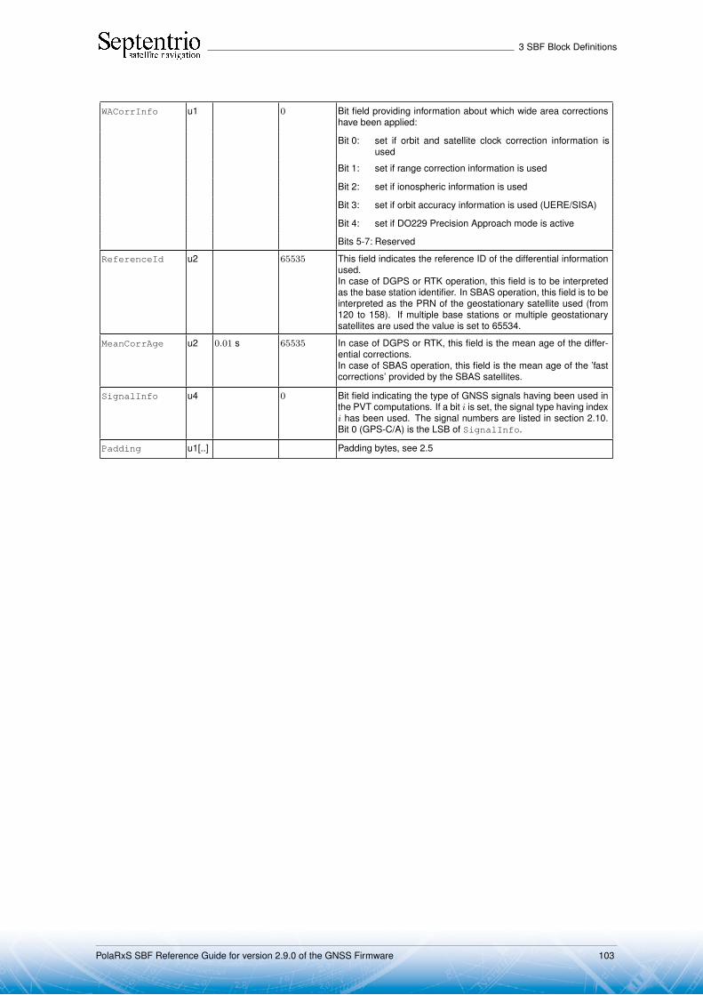
3 SBF Block Definitions
WACorrInfo u1 0 Bit field providing information about which wide area correctionshave been applied:
Bit 0: set if orbit and satellite clock correction information isused
Bit 1: set if range correction information is used
Bit 2: set if ionospheric information is used
Bit 3: set if orbit accuracy information is used (UERE/SISA)
Bit 4: set if DO229 Precision Approach mode is active
Bits 5-7: Reserved
ReferenceId u2 65535 This field indicates the reference ID of the differential informationused.In case of DGPS or RTK operation, this field is to be interpretedas the base station identifier. In SBAS operation, this field is to beinterpreted as the PRN of the geostationary satellite used (from120 to 158). If multiple base stations or multiple geostationarysatellites are used the value is set to 65534.
MeanCorrAge u2 0.01 s 65535 In case of DGPS or RTK, this field is the mean age of the differ-ential corrections.In case of SBAS operation, this field is the mean age of the ’fastcorrections’ provided by the SBAS satellites.
SignalInfo u4 0 Bit field indicating the type of GNSS signals having been used inthe PVT computations. If a bit i is set, the signal type having indexi has been used. The signal numbers are listed in section 2.10.Bit 0 (GPS-C/A) is the LSB of SignalInfo.
Padding u1[..] Padding bytes, see 2.5
PolaRxS SBF Reference Guide for version 2.9.0 of the GNSS Firmware 103
3 SBF Block Definitions
PosLocal Number: 4052"OnChange" interval: 10 ms
This block contains the position at the time specified in the TOW and WNc fields. The time ofapplicability is specified in the receiver time frame.
The position (Lat, Lon, Alt) relates to the local datum identified with the Datum field.The coordinate transformation to the local datum is done using parameters transmitted bythe RTK service provider in RTCM message types MT1021 to MT1023.
The position is that of the marker. The ARP-to-marker offset is set through the com-mand setAntennaOffset.
If no position is available, the Error field indicates the cause of the unavailability andall fields after the Error field are set to their respective Do-Not-Use values.
To be able to output a position in the PosLocal block, the receiver needs to have re-ceived the relevant RTCM transformation messages (at least either MT1021 or MT1022is required). If they have not been received yet, the local position is not available and theError field is set to value 17. See also section "Datum Transformation" in the FirmwareUser Manual.
The corresponding RTCMDatum block provides information on the local datum nameand transformation quality indicators. The corresponding RTCMDatum block is the one ofwhich the Datum field matches the Datum field in the PosLocal block.
PolaRxS SBF Reference Guide for version 2.9.0 of the GNSS Firmware 104

3 SBF Block Definitions
Parameter Type Units & Scale Do-Not-Use Description
Factor Value
Sync1 c1
Block Header, see 2.1
Sync2 c1
CRC u2
ID u2
Length u2 1 byte
TOW u4 0.001 s 4294967295Receiver time stamp, see 2.3
WNc u2 1 week 65535
Mode u1 Bit field indicating the PVT mode, as follows:
Bits 0-3: type of PVT solution:0: No PVT available (the Error field indicates the
cause of the absence of the PVT solution)1: Stand-Alone PVT2: Differential PVT3: Fixed location4: RTK with fixed ambiguities5: RTK with float ambiguities6: SBAS aided PVT7: moving-base RTK with fixed ambiguities8: moving-base RTK with float ambiguities10: Precise Point Positioning (PPP)
Bits 4-5: Reserved
Bit 6: Set if the user has entered the commandsetPVTMode,base,auto and the receiver is stillin the process of determining its fixed position.
Bit 7: 2D/3D flag: set in 2D mode (height assumed constantand not computed).
Error u1 PVT error code. The following values are defined:0: No Error1: Not enough measurements2: Not enough ephemerides available3: DOP too large (larger than 15)4: Sum of squared residuals too large5: No convergence6: Not enough measurements after outlier rejection7: Position output prohibited due to export laws8: Not enough differential corrections available9: Base station coordinates unavailable10: Ambiguities not fixed and user requested to only output RTK-
fixed positions17: Datum transformation parameters unknown
Note: if this field has a non-zero value, all following fields are setto their Do-Not-Use value.
Lat f8 1 rad −2 · 1010 Marker latitude, from −π/2 to +π/2, positive North of Equator
Lon f8 1 rad −2 · 1010 Marker latitude, from −π to +π, positive North of Equator
Alt f8 1 m −2 · 1010 Marker height. See the HeightType field of the correspondingRTCMDatum block for the interpretation of the height.
Datum u1 Reference frame to which the position relates. Internal ID ofthe local target datum from RTCMv3 MT1021/1022, from 20 to24. The corresponding datum parameters can be found in theRTCMDatum block having a matching Datum field.
PolaRxS SBF Reference Guide for version 2.9.0 of the GNSS Firmware 105

3 SBF Block Definitions
Padding u1[..] Padding bytes, see 2.5
PolaRxS SBF Reference Guide for version 2.9.0 of the GNSS Firmware 106

3 SBF Block Definitions
PosProjected Number: 4094
"OnChange" interval: 10 ms
This block contains the projected coordinates at the time specified in the TOW and WNc fields.The time of applicability is specified in the receiver time frame.
The coordinates (Northing, Easting, Alt) relate to the local datum identified with theDatum field. The coordinate transformation and projection is done using parameterstransmitted by the RTK service provider in RTCM message types MT1021 to MT1027.
The position is that of the marker. The ARP-to-marker offset is set through the com-mand setAntennaOffset.
If no position is available, the Error field indicates the cause of the unavailability andall fields after the Error field are set to their respective Do-Not-Use values.
To be able to output a position in the PosProjected block, the receiver needs tohave received at least one RTCM message in the MT1025 to MT1027 range. If none ofthese messages is sent out by the service provider, or if they have not been received yet, theprojected position is not available and the Error field is set to value 17. See also section"Datum Transformation" in the Firmware User Manual.
The corresponding RTCMDatum block provides information on the local datum nameand transformation/projection quality indicators. The corresponding RTCMDatum block is theone of which the Datum field matches the Datum field in the PosProjected block.
PolaRxS SBF Reference Guide for version 2.9.0 of the GNSS Firmware 107
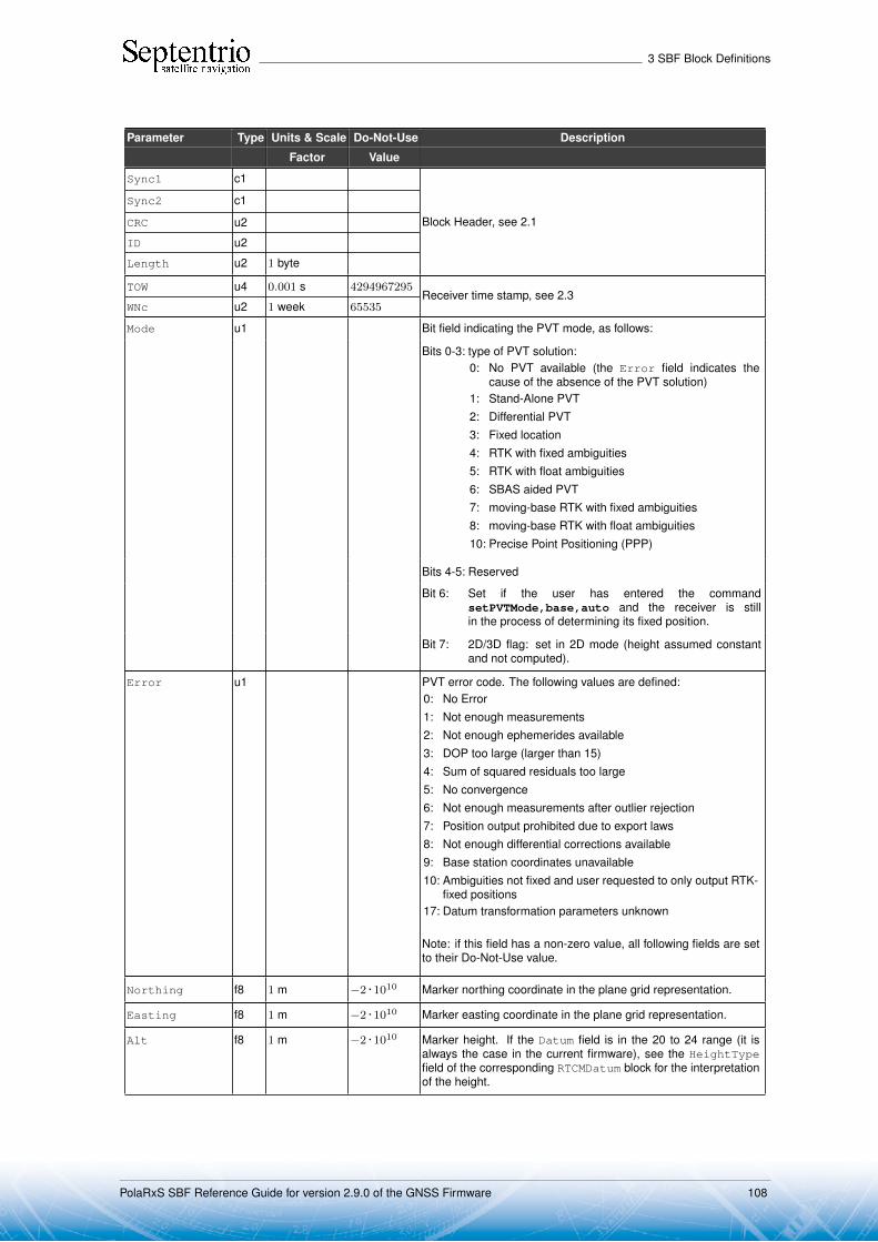
3 SBF Block Definitions
Parameter Type Units & Scale Do-Not-Use Description
Factor Value
Sync1 c1
Block Header, see 2.1
Sync2 c1
CRC u2
ID u2
Length u2 1 byte
TOW u4 0.001 s 4294967295Receiver time stamp, see 2.3
WNc u2 1 week 65535
Mode u1 Bit field indicating the PVT mode, as follows:
Bits 0-3: type of PVT solution:0: No PVT available (the Error field indicates the
cause of the absence of the PVT solution)1: Stand-Alone PVT2: Differential PVT3: Fixed location4: RTK with fixed ambiguities5: RTK with float ambiguities6: SBAS aided PVT7: moving-base RTK with fixed ambiguities8: moving-base RTK with float ambiguities10: Precise Point Positioning (PPP)
Bits 4-5: Reserved
Bit 6: Set if the user has entered the commandsetPVTMode,base,auto and the receiver is stillin the process of determining its fixed position.
Bit 7: 2D/3D flag: set in 2D mode (height assumed constantand not computed).
Error u1 PVT error code. The following values are defined:0: No Error1: Not enough measurements2: Not enough ephemerides available3: DOP too large (larger than 15)4: Sum of squared residuals too large5: No convergence6: Not enough measurements after outlier rejection7: Position output prohibited due to export laws8: Not enough differential corrections available9: Base station coordinates unavailable10: Ambiguities not fixed and user requested to only output RTK-
fixed positions17: Datum transformation parameters unknown
Note: if this field has a non-zero value, all following fields are setto their Do-Not-Use value.
Northing f8 1 m −2 · 1010 Marker northing coordinate in the plane grid representation.
Easting f8 1 m −2 · 1010 Marker easting coordinate in the plane grid representation.
Alt f8 1 m −2 · 1010 Marker height. If the Datum field is in the 20 to 24 range (it isalways the case in the current firmware), see the HeightTypefield of the corresponding RTCMDatum block for the interpretationof the height.
PolaRxS SBF Reference Guide for version 2.9.0 of the GNSS Firmware 108

3 SBF Block Definitions
Datum u1 Reference frame to which the coordinates relate. If the valueis in the 20 to 24 range (it is always the case in the currentfirmware), the corresponding datum parameters can be found inthe RTCMDatum block having a matching Datum field.
Padding u1[..] Padding bytes, see 2.5
PolaRxS SBF Reference Guide for version 2.9.0 of the GNSS Firmware 109

3 SBF Block Definitions
PVTSatCartesian Number: 4008"OnChange" interval: 10 ms
This block contains the position and velocity of all the satellites used in the PVT solution,together with slant ionospheric and tropospheric delays. Coordinates are referred to thetime of signal transmission computed by the receiver and are corrected for the Sagnac effect.
The reference frame the coordinates are related to is the one specified in the respec-tive ICDs (WGS84 for GPS satellites, GTRF for Galileo satellites, PZ90 for GLONASSsatellites, etc).
Parameter Type Units & Scale Do-Not-Use Description
Factor Value
Sync1 c1
Block Header, see 2.1
Sync2 c1
CRC u2
ID u2
Length u2 1 byte
TOW u4 0.001 s 4294967295Receiver time stamp, see 2.3
WNc u2 1 week 65535
N u1 Number of satellites for which satellite position is provided in thisSBF block, i.e. number of SatPos sub-blocks. If N is 0, there areno satellite positions available for this epoch.
SBLength u1 1 byte Length of one sub-block
SatPos ... ... A succession of N SatPos sub-blocks, see definition below
Padding u1[..] Padding bytes, see 2.5
SatPos sub-block definition:
Parameter Type Units & Scale Do-Not-Use Description
Factor Value
SVID u1 Satellite ID, see 2.9
FreqNr u1 0 For GLONASS satellites, this is the frequency number, with anoffset of 8. It ranges from 1 (corresponding to an actual frequencynumber of -7) to 21 (corresponding to an actual frequency numberof 13). For non-GLONASS satellites, FreqNr is reserved andmust be ignored by the decoding software.
IODE u2 IODE of the data set used to compute the values in this sub-block.
x f8 1 m −2 · 1010 X coordinate
y f8 1 m −2 · 1010 Y coordinate
z f8 1 m −2 · 1010 Z coordinate
Vx f4 1 m / s −2 · 1010 Satellite velocity in the X direction
Vy f4 1 m / s −2 · 1010 Satellite velocity in the Y direction
Vz f4 1 m / s −2 · 1010 Satellite velocity in the Z direction
Rev 1
IonoMSB i2 1 dm −32768 (7) Total slant ionospheric delay at the L1 carrier frequency(1575.42MHz), with a decimeter resolution.
TropoMSB i2 1 dm −32768 (8) Total slant tropospheric delay, with a decimeter resolution.
(7) The ionospheric delay should not be used when IonoMSB is -32768.(8) The tropospheric delay should not be used when TropoMSB is -32768.
PolaRxS SBF Reference Guide for version 2.9.0 of the GNSS Firmware 110

3 SBF Block Definitions
IonoLSB u1 1.0/256.0 dm 0 (7) Sub-decimeter part of the slant ionospheric delay. The high-resolution ionospheric delay, expressed in meters, can be com-puted as:IonoDelay[m] = 0.1*(IonoMSB + IonoLSB/256)
TropoLSB u1 1.0/256.0 dm 0 (8) Sub-decimeter part of the slant tropospheric delay. The high-resolution tropospheric delay, expressed in meters, can be com-puted as:TropoDelay[m] = 0.1*(TropoMSB + TropoLSB/256)
IonoModel u1 Model used to compute the ionospheric delay:0: Not applicable1: Klobuchar2: DO2293: NeQuick4: Measured (from dual frequency measurements)5: Estimated
Rev 1
Padding u1[..] Padding bytes, see 2.5
PolaRxS SBF Reference Guide for version 2.9.0 of the GNSS Firmware 111

3 SBF Block Definitions
PVTResiduals Number: 4009"OnChange" interval: 10 ms
This block contains the residuals of all measurements used in PVT solution computed atthe epoch specified in the TOW and WNc fields. The PVT solution itself can be found in thePVTCartesian or PVTGeodetic blocks.
For each measurement from each satellite and each modulation used in the PVT so-lution, detailed PVT residual information is output for each observable type (code phase,carrier phase and Doppler):
• a-posteriori measurement residual (ei)• absolute value of the w-test statistic (wi)• Minimal detectable bias (MDB).
In case of multi-base differential operation, a set of residuals is provided for all base stations.
This block uses a two-level sub-block structure analogous to that of the MeasEpochblock. It contains one SatSignalInfo sub-block for each satellite/signal type pair used inthe PVT or attitude computation. Each SatSignalInfo sub-block contains a number ofResidualInfo sub-blocks, each of them containing the residuals of a given observabletype.
The standard deviation of the residual (σe) for satellite i and the "a priori" measure-ment standard deviation (σy) can be computed from ei, wi and MDB by using the followingformulas (see also the Firmware User Manual):
σei =|ei|wi
and σyi =
√MDB√λ0
.σei
where λ0 is the non-centrality parameter and:√λ0 =
√2[erfinv(1− Pfa) + erfinv(1− 2Pmd)]
with Pfa and Pmd being the probability of false alarm and of missed detection respectively,as set by the setRAIMLevels command, and the "erfinv" function being the inverse errorfunction. The output of erfinv(x) is the value y that satisfies the following equality:
x =2√π
∫ y
0e−t
2dt
This block can be used to monitor the quality of the measurements. Under normal circum-stances, the residuals lie within -2 and +2 times the a-priori variance of the correspondingmeasurements.
PolaRxS SBF Reference Guide for version 2.9.0 of the GNSS Firmware 112

3 SBF Block Definitions
Parameter Type Units & Scale Do-Not-Use Description
Factor Value
Sync1 c1
Block Header, see 2.1
Sync2 c1
CRC u2
ID u2
Length u2 1 byte
TOW u4 0.001 s 4294967295Receiver time stamp, see 2.3
WNc u2 1 week 65535
N u1 Number of satellite/signal pairs for which residual blocks are pro-vided in this SBF block, i.e. number of SatSignalInfo sub-blocks. If N is 0, there are no satellite residuals available for thisepoch.
SB1Length u1 1 byte Length of a SatSignalInfo sub-block, excluding thenested ResidualInfoCode, ResidualInfoPhase andResidualInfoDoppler sub-blocks
SB2Length u1 1 byte Length of a ResidualInfoCode, ResidualInfoPhase andResidualInfoDoppler sub-block
Reserved u1[3] Reserved for future use, to be ignored by decoding software
Residuals ... ... A succession of N SatSignalInfo sub-blocks, see definitionbelow
Padding u1[..] Padding bytes, see 2.5
PolaRxS SBF Reference Guide for version 2.9.0 of the GNSS Firmware 113

3 SBF Block Definitions
SatSignalInfo sub-block definition:
Parameter Type Units & Scale Do-Not-Use Description
Factor Value
SVID u1 Satellite ID, see 2.9
FreqNr u1 0 For GLONASS satellites, this is the frequency number, with anoffset of 8. It ranges from 1 (corresponding to an actual fre-quency number of -7) to 21 (corresponding to an actual fre-quency number of 13). For non-GLONASS satellites, FreqNris reserved and must be ignored by the decoding software.
Type u1 Bit field indicating the signal type and antenna ID:
Bits 0-4: signal number as defined in 2.10.
Bits 5-7: Antenna ID: 0 for the main antenna
RefSVID u1 255, 62 Satellite ID of the reference satellite used for double differenc-ing, see 2.9.
Set to 255 if not in double difference mode, or set to 62if in double difference mode, and GLONASS slot numberunknown.
RefFreqNr u1 255, 0 GLONASS frequency number for the reference satellite, see2.9.
Set to 255 if not in double difference mode, or set to 0 ifin double difference mode, but non-GLONASS satellite.
MeasInfo u1 Bit field:
Bits 0-1: Type of residual this sub-block refers to:0: zero-difference residual (standalone)1: single-difference residual (SBAS, DGPS)2: double-difference residual. If the antenna ID is 0
(see the Type field above), this sub-block containsan RTK residual, else it contains an attitude resid-ual.
Bit 2: Set if a ResidualInfoCode sub-block containingpseudorange residuals follows.
Bit 3: Set if a ResidualInfoPhase sub-block containingcarrier-phase residuals follows.
Bit 4: Set if a ResidualInfoDoppler sub-block containingDoppler residuals follows.
Bits 5-6: Reserved
Bit 7: Set if ambiguity is fixed for the signal type identified bythe Type field.
The number of ResidualInfo sub-blocks to follow is equal tothe number of bits set to 1 between bit 2 and bit 4. The orderof these ResidualInfo sub-blocks is fixed: the code-phaseresiduals come first (if any), then the carrier phase residuals (ifany), and the Doppler residuals as last.
IODE u2 Issue of Data Ephemeris used for the satellite and signal typeidentified by SVID and Type.
CorrAge u2 0.001 s 65535 Age of corrections, either from SBAS, DGPS, RTK etc, trun-cated to 655.34 seconds.
ReferenceID u2 65535 ID of the base station the residuals apply to. Set to 65535 incase of standalone operation.Rev 1
Padding u1[..] Padding bytes, see 2.5
If the Pseudorange residuals field is 1 then this sub block is available:
ResidualInfoCode ... ... A ResidualInfoCode sub-block, see definition below
PolaRxS SBF Reference Guide for version 2.9.0 of the GNSS Firmware 114
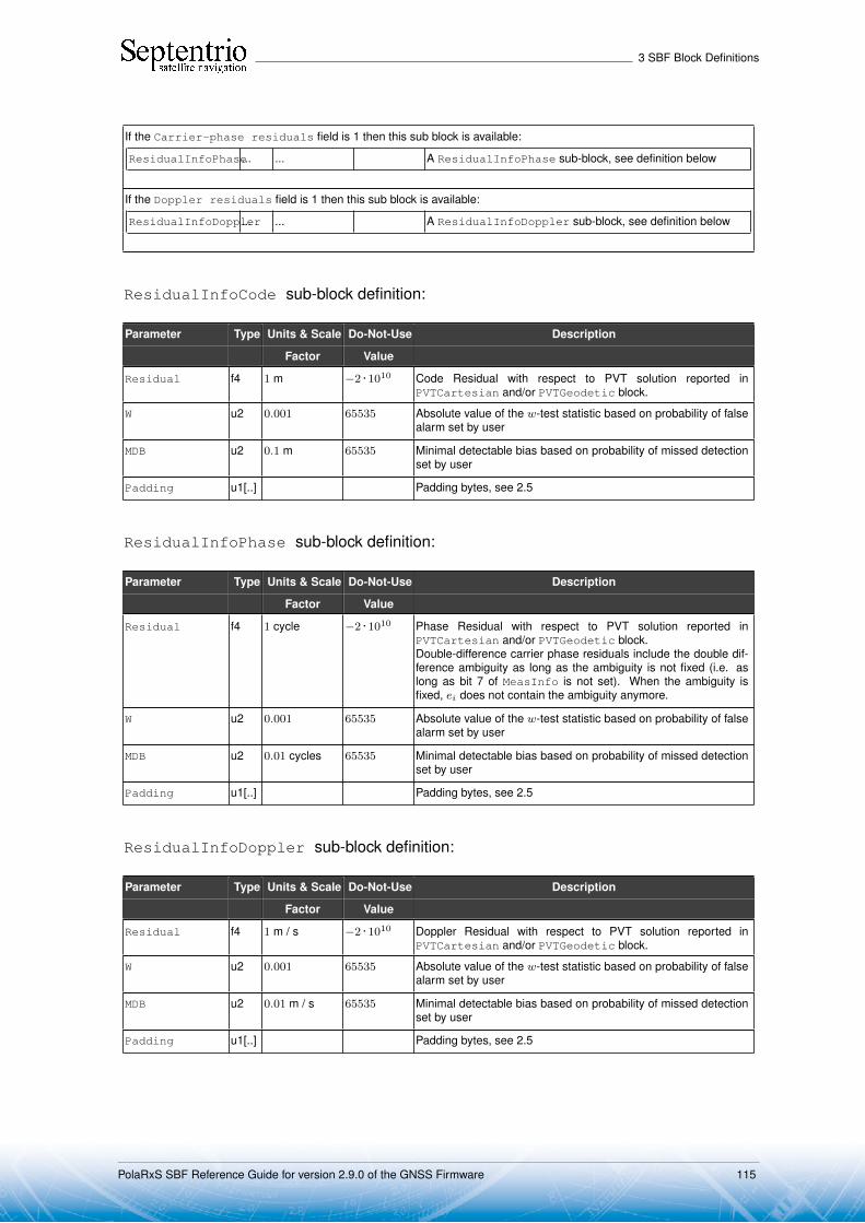
3 SBF Block Definitions
If the Carrier-phase residuals field is 1 then this sub block is available:
ResidualInfoPhase... ... A ResidualInfoPhase sub-block, see definition below
If the Doppler residuals field is 1 then this sub block is available:
ResidualInfoDoppler... ... A ResidualInfoDoppler sub-block, see definition below
ResidualInfoCode sub-block definition:
Parameter Type Units & Scale Do-Not-Use Description
Factor Value
Residual f4 1 m −2 · 1010 Code Residual with respect to PVT solution reported inPVTCartesian and/or PVTGeodetic block.
W u2 0.001 65535 Absolute value of the w-test statistic based on probability of falsealarm set by user
MDB u2 0.1 m 65535 Minimal detectable bias based on probability of missed detectionset by user
Padding u1[..] Padding bytes, see 2.5
ResidualInfoPhase sub-block definition:
Parameter Type Units & Scale Do-Not-Use Description
Factor Value
Residual f4 1 cycle −2 · 1010 Phase Residual with respect to PVT solution reported inPVTCartesian and/or PVTGeodetic block.Double-difference carrier phase residuals include the double dif-ference ambiguity as long as the ambiguity is not fixed (i.e. aslong as bit 7 of MeasInfo is not set). When the ambiguity isfixed, ei does not contain the ambiguity anymore.
W u2 0.001 65535 Absolute value of the w-test statistic based on probability of falsealarm set by user
MDB u2 0.01 cycles 65535 Minimal detectable bias based on probability of missed detectionset by user
Padding u1[..] Padding bytes, see 2.5
ResidualInfoDoppler sub-block definition:
Parameter Type Units & Scale Do-Not-Use Description
Factor Value
Residual f4 1 m / s −2 · 1010 Doppler Residual with respect to PVT solution reported inPVTCartesian and/or PVTGeodetic block.
W u2 0.001 65535 Absolute value of the w-test statistic based on probability of falsealarm set by user
MDB u2 0.01 m / s 65535 Minimal detectable bias based on probability of missed detectionset by user
Padding u1[..] Padding bytes, see 2.5
PolaRxS SBF Reference Guide for version 2.9.0 of the GNSS Firmware 115

3 SBF Block Definitions
RAIMStatistics Number: 4011"OnChange" interval: 10 ms
This block contains the integrity statistics that are computed by the receiver RAIM algorithm.
The output of the RAIM algorithm contains integrity information, which can be used inuser applications. First, the RAIM algorithm generates its own integrity flag based on theprobability of false-alarm, which can be used by a user as a receiver-level indication ofpositional integrity. If the internal integrity test is successful, a user has an opportunity tointroduce a more stringent application-specific integrity criterion by using External ReliabilityLevels (XERL). The positional solution is deemed as passed an application-level integritytest if the XERLs are within user-defined (and application-dependent) alarm limits. Thiscomparison (and the definition of alarm limits as well) takes place in a user application andis outside of the receiver scope. Please refer to the RAIM section of the Firmware UserManual for further details.
Parameter Type Units & Scale Do-Not-Use Description
Factor Value
Sync1 c1
Block Header, see 2.1
Sync2 c1
CRC u2
ID u2
Length u2 1 byte
TOW u4 0.001 s 4294967295Receiver time stamp, see 2.3
WNc u2 1 week 65535
IntegrityFlag u1 RAIM integrity flag:0: Integrity test successful1: Integrity test failed2: Integrity not available
Reserved1 u1 Reserved for future use, to be ignored by decoding software
HERL-position f4 1 m −2 · 1010 Horizontal external reliability level of the position
VERL-position f4 1 m −2 · 1010 Vertical external reliability level of the position
HERL-velocity f4 1 m / s −2 · 1010 Horizontal external reliability level of the velocity
VERL-velocity f4 1 m / s −2 · 1010 Vertical external reliability level of the velocity
OverallModel u2 1/50000 65535 (9) Overall model test statistic for the estimated PVT parameters di-vided by the test threshold
Padding u1[..] Padding bytes, see 2.5
(9) This field is clipped to 65534, i.e. if the actual value is larger than 65534, it is set to 65534.
PolaRxS SBF Reference Guide for version 2.9.0 of the GNSS Firmware 116

3 SBF Block Definitions
GEOCorrections Number: 5935"OnChange" interval: 10 ms
This block contains the SBAS corrections that the receiver has applied to the pseudorangesused in the PVT computation computed at the epoch specified in the TOW and WNc fields.The PVT solution itself can be found in the PVTCartesian or PVTGeodetic blocks.
The corrections are based on the messages received from an SBAS satellite. Theycompensate for the following errors:
• Satellite orbit• Satellite clock• Ionospheric delay.
Parameter Type Units & Scale Do-Not-Use Description
Factor Value
Sync1 c1
Block Header, see 2.1
Sync2 c1
CRC u2
ID u2
Length u2 1 byte
TOW u4 0.001 s 4294967295Receiver time stamp, see 2.3
WNc u2 1 week 65535
N u1 Number of satellites for which corrections are provided in this SBFblock, i.e. number of SatCorr sub-blocks. If N is 0, there are nocorrections available for this epoch.
SBLength u1 1 byte Length of one sub-block in bytes
SatCorr ... ... A succession of N SatCorr sub-blocks, see definition below
Padding u1[..] Padding bytes, see 2.5
SatCorr sub-block definition:
Parameter Type Units & Scale Do-Not-Use Description
Factor Value
SVID u1 Satellite ID, see 2.9
IODE u1 Issue of Data Ephemeris related to the orbit and clock corrections
Reserved u1[2] Reserved for future use, to be ignored by decoding software
PRC f4 1 m Applied pseudorange correction based on the fast correction datareceived in MT02-MT05 or MT24
CorrAgeFC f4 1 s Age of applied fast correction
DeltaX f4 1 m X-component of applied orbit correction based on the long termcorrection data received in MT24 or MT25
DeltaY f4 1 m Y-component of applied orbit correction based on the long termcorrection data received in MT24 or MT25
DeltaZ f4 1 m Z-component of applied orbit correction based on the long termcorrection data received in MT24 or MT25
DeltaClock f4 1 s Satellite clock correction based on the long term correction datareceived in MT24 or MT25
CorrAgeLT f4 1 s Age of applied long term correction
IonoPPlat f4 1 rad −2 · 1010 Latitude of ionospheric pierce point
PolaRxS SBF Reference Guide for version 2.9.0 of the GNSS Firmware 117

3 SBF Block Definitions
IonoPPlon f4 1 rad −2 · 1010 Longitude of ionospheric pierce point
SlantIono f4 1 m −2 · 1010 Slant ionospheric delay at the L1 carrier at the ionosphere piercepoint based on the data received in MT18 and MT26
CorrAgeIono f4 1 s −2 · 1010 Maximum of the ionospheric correction age at each of the gridlocations used for the interpolation of the ionospheric delay.
VarFLT f4 1 m2 −2 · 1010 Variance of fast and long-term corrections (used for XPL compu-tation)
VarUIRE f4 1 m2 −2 · 1010 Variance of ionospheric delay corrections (used for XPL compu-tation)
VarAir f4 1 m2 −2 · 1010 Variance of unmodeled receiver errors, such as tracking noiseand multipath (used for XPL computation)
VarTropo f4 1 m2 −2 · 1010 Variance of tropospheric delay corrections (used for XPL compu-tation)
Padding u1[..] Padding bytes, see 2.5
PolaRxS SBF Reference Guide for version 2.9.0 of the GNSS Firmware 118
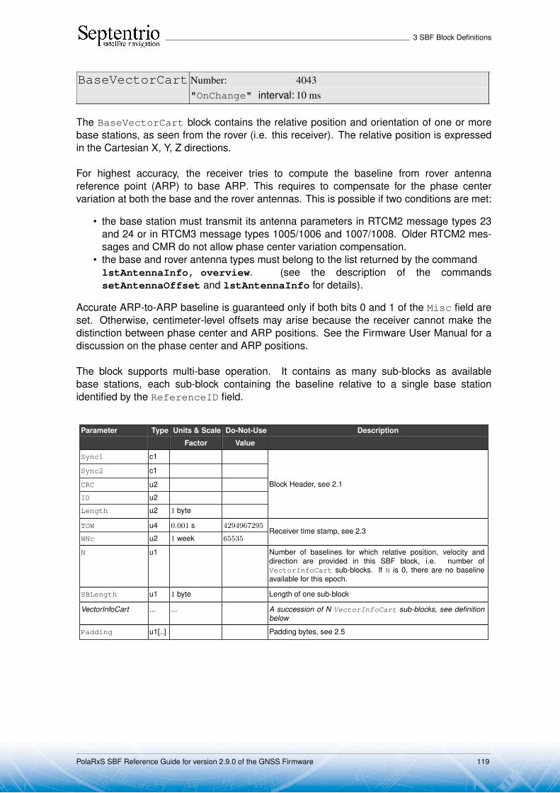
3 SBF Block Definitions
BaseVectorCart Number: 4043"OnChange" interval: 10 ms
The BaseVectorCart block contains the relative position and orientation of one or morebase stations, as seen from the rover (i.e. this receiver). The relative position is expressedin the Cartesian X, Y, Z directions.
For highest accuracy, the receiver tries to compute the baseline from rover antennareference point (ARP) to base ARP. This requires to compensate for the phase centervariation at both the base and the rover antennas. This is possible if two conditions are met:
• the base station must transmit its antenna parameters in RTCM2 message types 23and 24 or in RTCM3 message types 1005/1006 and 1007/1008. Older RTCM2 mes-sages and CMR do not allow phase center variation compensation.
• the base and rover antenna types must belong to the list returned by the commandlstAntennaInfo, overview. (see the description of the commandssetAntennaOffset and lstAntennaInfo for details).
Accurate ARP-to-ARP baseline is guaranteed only if both bits 0 and 1 of the Misc field areset. Otherwise, centimeter-level offsets may arise because the receiver cannot make thedistinction between phase center and ARP positions. See the Firmware User Manual for adiscussion on the phase center and ARP positions.
The block supports multi-base operation. It contains as many sub-blocks as availablebase stations, each sub-block containing the baseline relative to a single base stationidentified by the ReferenceID field.
Parameter Type Units & Scale Do-Not-Use Description
Factor Value
Sync1 c1
Block Header, see 2.1
Sync2 c1
CRC u2
ID u2
Length u2 1 byte
TOW u4 0.001 s 4294967295Receiver time stamp, see 2.3
WNc u2 1 week 65535
N u1 Number of baselines for which relative position, velocity anddirection are provided in this SBF block, i.e. number ofVectorInfoCart sub-blocks. If N is 0, there are no baselineavailable for this epoch.
SBLength u1 1 byte Length of one sub-block
VectorInfoCart ... ... A succession of N VectorInfoCart sub-blocks, see definitionbelow
Padding u1[..] Padding bytes, see 2.5
PolaRxS SBF Reference Guide for version 2.9.0 of the GNSS Firmware 119

3 SBF Block Definitions
VectorInfoCart sub-block definition:
Parameter Type Units & Scale Do-Not-Use Description
Factor Value
nrSV u1 Number of satellites for which corrections are available from thebase station identified by the ReferenceID field.
Error u1 PVT error code. The following values are defined:0: No Error1: Not enough measurements2: Not enough ephemerides available3: DOP too large (larger than 15)4: Sum of squared residuals too large5: No convergence6: Not enough measurements after outlier rejection7: Position output prohibited due to export laws8: Not enough differential corrections available9: Base station coordinates unavailable10: Ambiguities not fixed and user requested to only output RTK-
fixed positions
Note: if this field has a non-zero value, all following fields are setto their Do-Not-Use value.
Mode u1 Bit field indicating the PVT mode, as follows:
Bits 0-3: type of PVT solution:0: No PVT available (the Error field indicates the
cause of the absence of the PVT solution)1: Stand-Alone PVT2: Differential PVT3: Fixed location4: RTK with fixed ambiguities5: RTK with float ambiguities6: SBAS aided PVT7: moving-base RTK with fixed ambiguities8: moving-base RTK with float ambiguities10: Precise Point Positioning (PPP)
Bits 4-5: Reserved
Bit 6: Set if the user has entered the commandsetPVTMode,base,auto and the receiver is stillin the process of determining its fixed position.
Bit 7: 2D/3D flag: set in 2D mode (height assumed constantand not computed).
Misc u1 Bit field containing miscellaneous flags:
Bit 0: Set if the baseline points to the base station ARP. Unsetif it points to the antenna phase center, or if unknown.
Bit 1: Set if the phase center variation is compensated for atthe rover (i.e. the baseline starts from the antenna ARP),unset if not or unknown.
Bit 2: Proprietary.
Bits 3-7: Reserved
DeltaX f8 1 m −2 · 1010 X baseline component (from rover to base)
DeltaY f8 1 m −2 · 1010 Y baseline component (from rover to base)
DeltaZ f8 1 m −2 · 1010 Z baseline component (from rover to base)
DeltaVx f4 1 m / s −2 · 1010 X velocity of base with respect to rover
PolaRxS SBF Reference Guide for version 2.9.0 of the GNSS Firmware 120
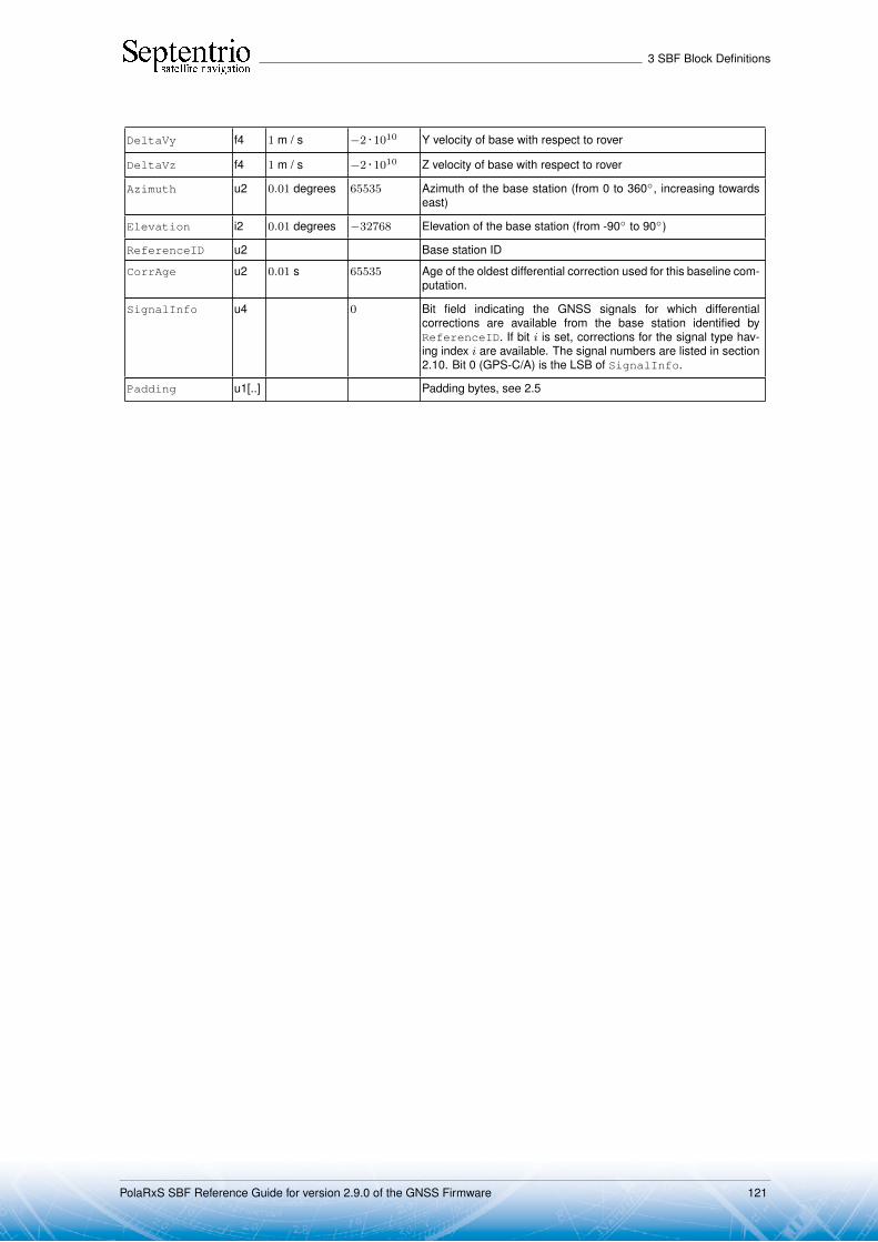
3 SBF Block Definitions
DeltaVy f4 1 m / s −2 · 1010 Y velocity of base with respect to rover
DeltaVz f4 1 m / s −2 · 1010 Z velocity of base with respect to rover
Azimuth u2 0.01 degrees 65535 Azimuth of the base station (from 0 to 360◦, increasing towardseast)
Elevation i2 0.01 degrees −32768 Elevation of the base station (from -90◦ to 90◦)
ReferenceID u2 Base station ID
CorrAge u2 0.01 s 65535 Age of the oldest differential correction used for this baseline com-putation.
SignalInfo u4 0 Bit field indicating the GNSS signals for which differentialcorrections are available from the base station identified byReferenceID. If bit i is set, corrections for the signal type hav-ing index i are available. The signal numbers are listed in section2.10. Bit 0 (GPS-C/A) is the LSB of SignalInfo.
Padding u1[..] Padding bytes, see 2.5
PolaRxS SBF Reference Guide for version 2.9.0 of the GNSS Firmware 121
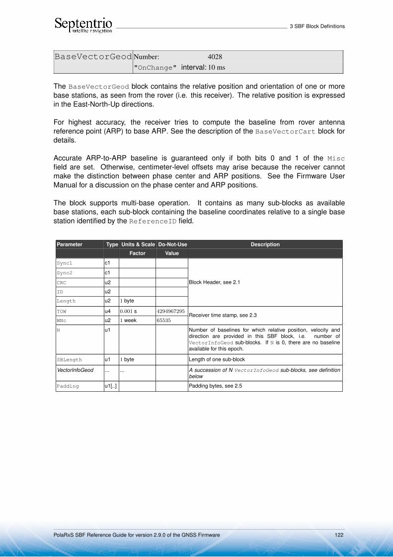
3 SBF Block Definitions
BaseVectorGeod Number: 4028"OnChange" interval: 10 ms
The BaseVectorGeod block contains the relative position and orientation of one or morebase stations, as seen from the rover (i.e. this receiver). The relative position is expressedin the East-North-Up directions.
For highest accuracy, the receiver tries to compute the baseline from rover antennareference point (ARP) to base ARP. See the description of the BaseVectorCart block fordetails.
Accurate ARP-to-ARP baseline is guaranteed only if both bits 0 and 1 of the Miscfield are set. Otherwise, centimeter-level offsets may arise because the receiver cannotmake the distinction between phase center and ARP positions. See the Firmware UserManual for a discussion on the phase center and ARP positions.
The block supports multi-base operation. It contains as many sub-blocks as availablebase stations, each sub-block containing the baseline coordinates relative to a single basestation identified by the ReferenceID field.
Parameter Type Units & Scale Do-Not-Use Description
Factor Value
Sync1 c1
Block Header, see 2.1
Sync2 c1
CRC u2
ID u2
Length u2 1 byte
TOW u4 0.001 s 4294967295Receiver time stamp, see 2.3
WNc u2 1 week 65535
N u1 Number of baselines for which relative position, velocity anddirection are provided in this SBF block, i.e. number ofVectorInfoGeod sub-blocks. If N is 0, there are no baselineavailable for this epoch.
SBLength u1 1 byte Length of one sub-block
VectorInfoGeod ... ... A succession of N VectorInfoGeod sub-blocks, see definitionbelow
Padding u1[..] Padding bytes, see 2.5
PolaRxS SBF Reference Guide for version 2.9.0 of the GNSS Firmware 122

3 SBF Block Definitions
VectorInfoGeod sub-block definition:
Parameter Type Units & Scale Do-Not-Use Description
Factor Value
NrSV u1 Number of satellites for which corrections are available from thebase station identified by the ReferenceID field.
Error u1 PVT error code. The following values are defined:0: No Error1: Not enough measurements2: Not enough ephemerides available3: DOP too large (larger than 15)4: Sum of squared residuals too large5: No convergence6: Not enough measurements after outlier rejection7: Position output prohibited due to export laws8: Not enough differential corrections available9: Base station coordinates unavailable10: Ambiguities not fixed and user requested to only output RTK-
fixed positions
Note: if this field has a non-zero value, all following fields are setto their Do-Not-Use value.
Mode u1 Bit field indicating the PVT mode, as follows:
Bits 0-3: type of PVT solution:0: No PVT available (the Error field indicates the
cause of the absence of the PVT solution)1: Stand-Alone PVT2: Differential PVT3: Fixed location4: RTK with fixed ambiguities5: RTK with float ambiguities6: SBAS aided PVT7: moving-base RTK with fixed ambiguities8: moving-base RTK with float ambiguities10: Precise Point Positioning (PPP)
Bits 4-5: Reserved
Bit 6: Set if the user has entered the commandsetPVTMode,base,auto and the receiver is stillin the process of determining its fixed position.
Bit 7: 2D/3D flag: set in 2D mode (height assumed constantand not computed).
Misc u1 Bit field containing miscellaneous flags:
Bit 0: Set if the baseline points to the base station ARP. Unsetif it points to the antenna phase center, or if unknown.
Bit 1: Set if the phase center variation is compensated for atthe rover (i.e. the baseline starts from the antenna ARP),unset if not or unknown.
Bit 2: Proprietary.
Bits 3-7: Reserved
DeltaEast f8 1 m −2 · 1010 East baseline component (from rover to base)
DeltaNorth f8 1 m −2 · 1010 North baseline component (from rover to base)
DeltaUp f8 1 m −2 · 1010 Up baseline component (from rover to base)
DeltaVe f4 1 m / s −2 · 1010 East velocity of base with respect to rover
PolaRxS SBF Reference Guide for version 2.9.0 of the GNSS Firmware 123

3 SBF Block Definitions
DeltaVn f4 1 m / s −2 · 1010 North velocity of base with respect to rover
DeltaVu f4 1 m / s −2 · 1010 Up velocity of base with respect to rover
Azimuth u2 0.01 degrees 65535 Azimuth of the base station (from 0 to 360◦, increasing towardseast)
Elevation i2 0.01 degrees −32768 Elevation of the base station (from -90◦ to 90◦)
ReferenceID u2 Base station ID
CorrAge u2 0.01 s 65535 Age of the oldest differential correction used for this baseline com-putation.
SignalInfo u4 0 Bit field indicating the GNSS signals for which differential correc-tions are available from the base station identified by Referen-ceID. If bit i is set, corrections for the signal type having index iare available. The signal numbers are listed in section 2.10. Bit 0(GPS-C/A) is the LSB of SignalInfo.
Padding u1[..] Padding bytes, see 2.5
PolaRxS SBF Reference Guide for version 2.9.0 of the GNSS Firmware 124

3 SBF Block Definitions
PVTSupport Number: 4076
"OnChange" interval: 10 ms
This block is undocumented. It is for maintenance purpose only.
PolaRxS SBF Reference Guide for version 2.9.0 of the GNSS Firmware 125

3 SBF Block Definitions
EndOfPVT Number: 5921"OnChange" interval: 10 ms
This block marks the end of transmission of all PVT related blocks belonging to the sameepoch.
Parameter Type Units & Scale Do-Not-Use Description
Factor Value
Sync1 c1
Block Header, see 2.1
Sync2 c1
CRC u2
ID u2
Length u2 1 byte
TOW u4 0.001 s 4294967295Receiver time stamp, see 2.3
WNc u2 1 week 65535
Padding u1[..] Padding bytes, see 2.5
PolaRxS SBF Reference Guide for version 2.9.0 of the GNSS Firmware 126
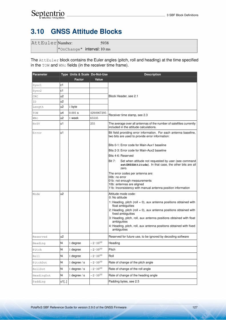
3 SBF Block Definitions
3.10 GNSS Attitude BlocksAttEuler Number: 5938
"OnChange" interval: 10 ms
The AttEuler block contains the Euler angles (pitch, roll and heading) at the time specifiedin the TOW and WNc fields (in the receiver time frame).
Parameter Type Units & Scale Do-Not-Use Description
Factor Value
Sync1 c1
Block Header, see 2.1
Sync2 c1
CRC u2
ID u2
Length u2 1 byte
TOW u4 0.001 s 4294967295Receiver time stamp, see 2.3
WNc u2 1 week 65535
NrSV u1 255 The average over all antennas of the number of satellites currentlyincluded in the attitude calculations.
Error u1 Bit field providing error information. For each antenna baseline,two bits are used to provide error information:
Bits 0-1: Error code for Main-Aux1 baseline
Bits 2-3: Error code for Main-Aux2 baseline
Bits 4-6: Reserved
Bit 7: Set when attitude not requested by user (see commandsetGNSSAttitude). In that case, the other bits are allzero.
The error codes per antenna are:00b: no error01b: not enough measurements10b: antennas are aligned11b: Inconsistency with manual antenna position information
Mode u2 Attitude mode code:0: No attitude1: Heading, pitch (roll = 0), aux antenna positions obtained with
float ambiguities2: Heading, pitch (roll = 0), aux antenna positions obtained with
fixed ambiguities3: Heading, pitch, roll, aux antenna positions obtained with float
ambiguities4: Heading, pitch, roll, aux antenna positions obtained with fixed
ambiguities
Reserved u2 Reserved for future use, to be ignored by decoding software
Heading f4 1 degree −2 · 1010 Heading
Pitch f4 1 degree −2 · 1010 Pitch
Roll f4 1 degree −2 · 1010 Roll
PitchDot f4 1 degree / s −2 · 1010 Rate of change of the pitch angle
RollDot f4 1 degree / s −2 · 1010 Rate of change of the roll angle
HeadingDot f4 1 degree / s −2 · 1010 Rate of change of the heading angle
Padding u1[..] Padding bytes, see 2.5
PolaRxS SBF Reference Guide for version 2.9.0 of the GNSS Firmware 127
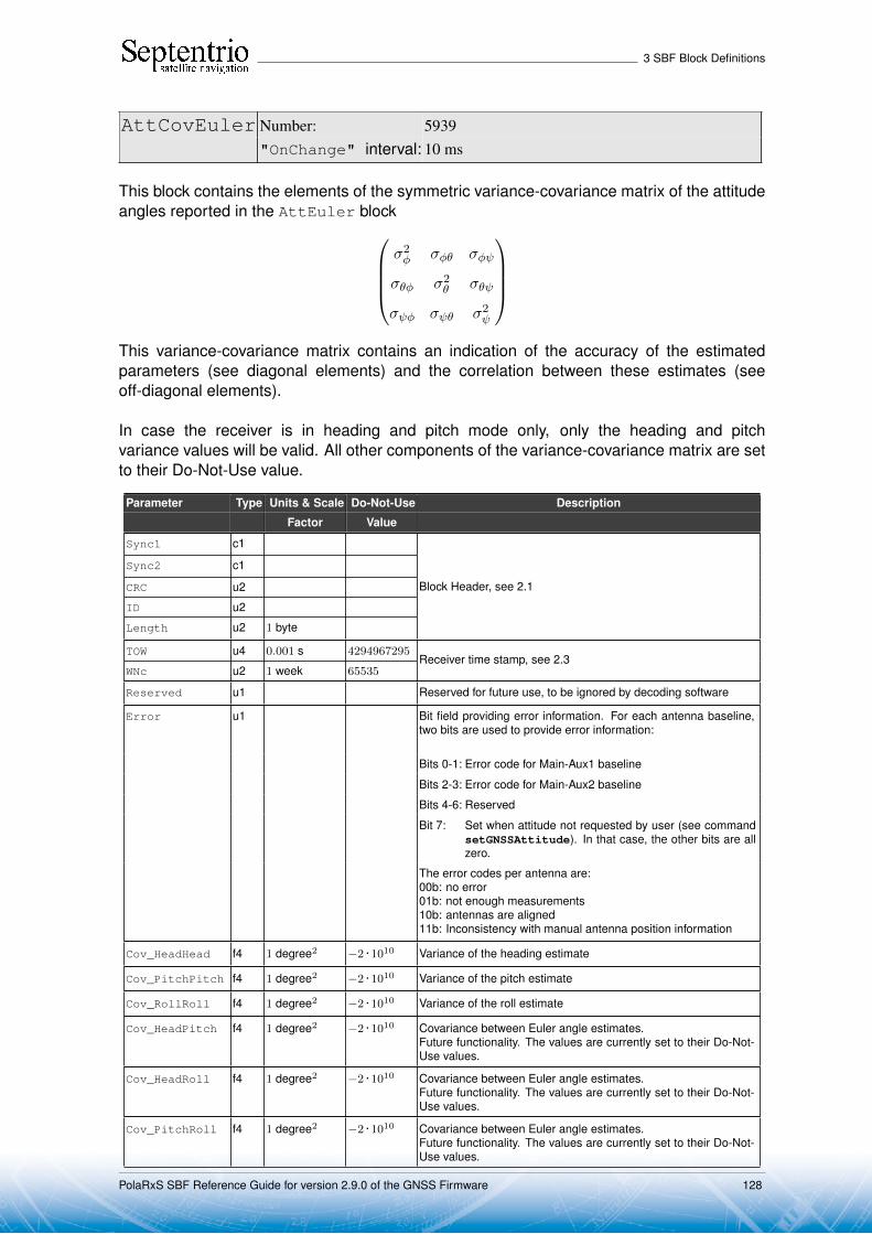
3 SBF Block Definitions
AttCovEuler Number: 5939"OnChange" interval: 10 ms
This block contains the elements of the symmetric variance-covariance matrix of the attitudeangles reported in the AttEuler block
σ2φ σφθ σφψ
σθφ σ2θ σθψ
σψφ σψθ σ2ψ
This variance-covariance matrix contains an indication of the accuracy of the estimatedparameters (see diagonal elements) and the correlation between these estimates (seeoff-diagonal elements).
In case the receiver is in heading and pitch mode only, only the heading and pitchvariance values will be valid. All other components of the variance-covariance matrix are setto their Do-Not-Use value.
Parameter Type Units & Scale Do-Not-Use Description
Factor Value
Sync1 c1
Block Header, see 2.1
Sync2 c1
CRC u2
ID u2
Length u2 1 byte
TOW u4 0.001 s 4294967295Receiver time stamp, see 2.3
WNc u2 1 week 65535
Reserved u1 Reserved for future use, to be ignored by decoding software
Error u1 Bit field providing error information. For each antenna baseline,two bits are used to provide error information:
Bits 0-1: Error code for Main-Aux1 baseline
Bits 2-3: Error code for Main-Aux2 baseline
Bits 4-6: Reserved
Bit 7: Set when attitude not requested by user (see commandsetGNSSAttitude). In that case, the other bits are allzero.
The error codes per antenna are:00b: no error01b: not enough measurements10b: antennas are aligned11b: Inconsistency with manual antenna position information
Cov_HeadHead f4 1 degree2 −2 · 1010 Variance of the heading estimate
Cov_PitchPitch f4 1 degree2 −2 · 1010 Variance of the pitch estimate
Cov_RollRoll f4 1 degree2 −2 · 1010 Variance of the roll estimate
Cov_HeadPitch f4 1 degree2 −2 · 1010 Covariance between Euler angle estimates.Future functionality. The values are currently set to their Do-Not-Use values.
Cov_HeadRoll f4 1 degree2 −2 · 1010 Covariance between Euler angle estimates.Future functionality. The values are currently set to their Do-Not-Use values.
Cov_PitchRoll f4 1 degree2 −2 · 1010 Covariance between Euler angle estimates.Future functionality. The values are currently set to their Do-Not-Use values.
PolaRxS SBF Reference Guide for version 2.9.0 of the GNSS Firmware 128

3 SBF Block Definitions
Padding u1[..] Padding bytes, see 2.5
PolaRxS SBF Reference Guide for version 2.9.0 of the GNSS Firmware 129

3 SBF Block Definitions
EndOfAtt Number: 5943"OnChange" interval: 10 ms
This block marks the end of transmission of all GNSS-attitude related blocks belonging tothe same epoch.
Parameter Type Units & Scale Do-Not-Use Description
Factor Value
Sync1 c1
Block Header, see 2.1
Sync2 c1
CRC u2
ID u2
Length u2 1 byte
TOW u4 0.001 s 4294967295Receiver time stamp, see 2.3
WNc u2 1 week 65535
Padding u1[..] Padding bytes, see 2.5
PolaRxS SBF Reference Guide for version 2.9.0 of the GNSS Firmware 130
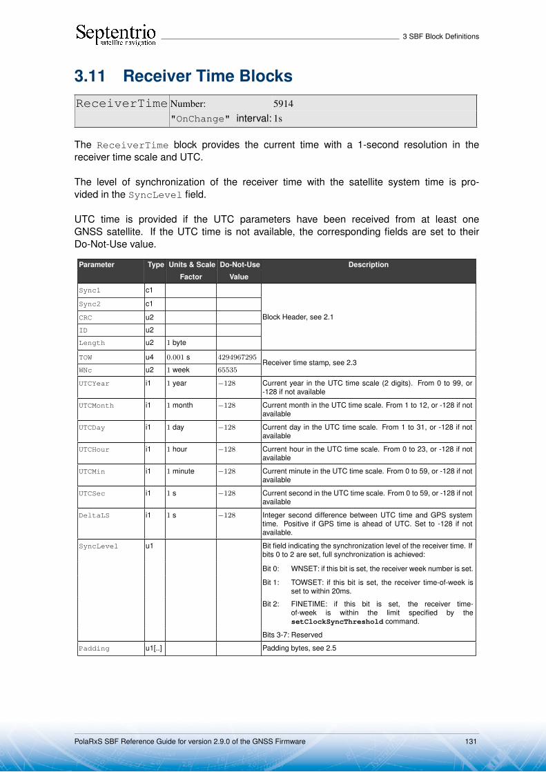
3 SBF Block Definitions
3.11 Receiver Time BlocksReceiverTime Number: 5914
"OnChange" interval: 1s
The ReceiverTime block provides the current time with a 1-second resolution in thereceiver time scale and UTC.
The level of synchronization of the receiver time with the satellite system time is pro-vided in the SyncLevel field.
UTC time is provided if the UTC parameters have been received from at least oneGNSS satellite. If the UTC time is not available, the corresponding fields are set to theirDo-Not-Use value.
Parameter Type Units & Scale Do-Not-Use Description
Factor Value
Sync1 c1
Block Header, see 2.1
Sync2 c1
CRC u2
ID u2
Length u2 1 byte
TOW u4 0.001 s 4294967295Receiver time stamp, see 2.3
WNc u2 1 week 65535
UTCYear i1 1 year −128 Current year in the UTC time scale (2 digits). From 0 to 99, or-128 if not available
UTCMonth i1 1 month −128 Current month in the UTC time scale. From 1 to 12, or -128 if notavailable
UTCDay i1 1 day −128 Current day in the UTC time scale. From 1 to 31, or -128 if notavailable
UTCHour i1 1 hour −128 Current hour in the UTC time scale. From 0 to 23, or -128 if notavailable
UTCMin i1 1 minute −128 Current minute in the UTC time scale. From 0 to 59, or -128 if notavailable
UTCSec i1 1 s −128 Current second in the UTC time scale. From 0 to 59, or -128 if notavailable
DeltaLS i1 1 s −128 Integer second difference between UTC time and GPS systemtime. Positive if GPS time is ahead of UTC. Set to -128 if notavailable.
SyncLevel u1 Bit field indicating the synchronization level of the receiver time. Ifbits 0 to 2 are set, full synchronization is achieved:
Bit 0: WNSET: if this bit is set, the receiver week number is set.
Bit 1: TOWSET: if this bit is set, the receiver time-of-week isset to within 20ms.
Bit 2: FINETIME: if this bit is set, the receiver time-of-week is within the limit specified by thesetClockSyncThreshold command.
Bits 3-7: Reserved
Padding u1[..] Padding bytes, see 2.5
PolaRxS SBF Reference Guide for version 2.9.0 of the GNSS Firmware 131

3 SBF Block Definitions
xPPSOffset Number: 5911"OnChange" interval: PPS rate
The xPPSOffset block contains the offset between the true xPPS pulse and the actualpulse output by the receiver. It is output right after each xPPS pulse.
Parameter Type Units & Scale Do-Not-Use Description
Factor Value
Sync1 c1
Block Header, see 2.1
Sync2 c1
CRC u2
ID u2
Length u2 1 byte
TOW u4 0.001 s 4294967295Receiver time stamp, see 2.3
WNc u2 1 week 65535
SyncAge u1 1 s Age of the last synchronization to system time. The xPPS pulseis regularly resynchronized with system time. This field indicatesthe number of seconds elapsed since the last resynchronization.SyncAge is constrained to the 0-255s range. If the age is higherthan 255s, SyncAge is set to 255.If the PPS is synchronized with the internal receiver time(Timescale = 3), SyncAge is always set to 0.
TimeScale u1 Time reference to which the xPPS pulse is referenced. The follow-ing values are defined (see also the setPPSParameters com-mand):1: GNSS system time specified by the setTimingSystem com-
mand2: UTC3: receiver time4: GLONASS time
Offset f4 1 · 10−9 s Offset of the xPPS output by the receiver with respect to its trueposition. Offset is negative when the xPPS pulse is in advancewith respect to its true position. See the Firmware User Manualfor an explanation of the xPPS generation principle, and for a de-scription of the xPPS offset.
Padding u1[..] Padding bytes, see 2.5
PolaRxS SBF Reference Guide for version 2.9.0 of the GNSS Firmware 132
3 SBF Block Definitions
3.12 External Event BlocksThese blocks report the state of the receiver applicable at the instant of a level transi-tion on one of its “Event” pins. The receiver time is reported in the ExtEvent SBFblock, and the receiver position is reported in the ExtEventPVTCartesian and theExtEventPVTGeodetic blocks.
If enabled, upon detection of an event, these three blocks are output in the following order,with no other SBF blocks in between them:
1. ExtEvent;2. ExtEventPVTCartesian;3. ExtEventPVTGeodetic.
All blocks referring to the same event contain the same time stamp in the TOW and WNc fields.
PolaRxS SBF Reference Guide for version 2.9.0 of the GNSS Firmware 133

3 SBF Block Definitions
ExtEvent Number: 5924"OnChange" interval: each time an event is detected
The ExtEvent block contains the time tag of a voltage transition on one of the "Event" inputpins.
This block is only output after the first position fix is available.
Parameter Type Units & Scale Do-Not-Use Description
Factor Value
Sync1 c1
Block Header, see 2.1
Sync2 c1
CRC u2
ID u2
Length u2 1 byte
TOW u4 0.001 s 4294967295External time stamp, see 2.3
WNc u2 1 week 65535
Source u1 Input pin where this external event has been detected. The fol-lowing values are defined:1: EventA2: EventB
Polarity u1 0: rising edge event1: falling edge event
Offset f4 1 s Event time offset with respect to TOW, including the potentialdelay specified with the setEventParameters command.
The time of week of the external event is given by:text,rx [s] = TOW/1000 + Offset
text,rx refers to the receiver system time scale. Use theRxClkBias field to convert this time to the GNSS time scale.
RxClkBias f8 1 s −2 · 1010 Receiver clock bias at the time of event. The clock bias isrelative to the system time specified by the setTimingSystemcommand. To get the time of week of the external event in thatsystem time scale, use:text,GNSS [s] = TOW/1000 + Offset - RxClkBias.
The accuracy of the clock bias is dependent on the age ofthe last PVT solution. When the receiver has been unable tocompute a PVT during the last 10 minutes, this field is set to itsDo-Not-Use value.
PVTAge u2 1 s Age of the last PVT solution. If the PVT age is larger than 10minutes (600s), this value is clipped to 600.Rev 1
Padding u1[..] Padding bytes, see 2.5
PolaRxS SBF Reference Guide for version 2.9.0 of the GNSS Firmware 134
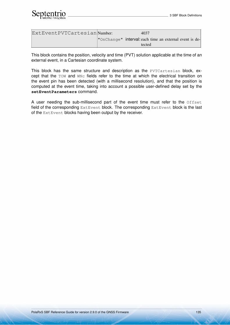
3 SBF Block Definitions
ExtEventPVTCartesian Number: 4037"OnChange" interval: each time an external event is de-
tected
This block contains the position, velocity and time (PVT) solution applicable at the time of anexternal event, in a Cartesian coordinate system.
This block has the same structure and description as the PVTCartesian block, ex-cept that the TOW and WNc fields refer to the time at which the electrical transition onthe event pin has been detected (with a millisecond resolution), and that the position iscomputed at the event time, taking into account a possible user-defined delay set by thesetEventParameters command.
A user needing the sub-millisecond part of the event time must refer to the Offsetfield of the corresponding ExtEvent block. The corresponding ExtEvent block is the lastof the ExtEvent blocks having been output by the receiver.
PolaRxS SBF Reference Guide for version 2.9.0 of the GNSS Firmware 135

3 SBF Block Definitions
Parameter Type Units & Scale Do-Not-Use Description
Factor Value
Sync1 c1
Block Header, see 2.1
Sync2 c1
CRC u2
ID u2
Length u2 1 byte
TOW u4 0.001 s 4294967295External time stamp, see 2.3
WNc u2 1 week 65535
Mode u1 Bit field indicating the PVT mode, as follows:
Bits 0-3: type of PVT solution:0: No PVT available (the Error field indicates the
cause of the absence of the PVT solution)1: Stand-Alone PVT2: Differential PVT3: Fixed location4: RTK with fixed ambiguities5: RTK with float ambiguities6: SBAS aided PVT7: moving-base RTK with fixed ambiguities8: moving-base RTK with float ambiguities10: Precise Point Positioning (PPP)
Bits 4-5: Reserved
Bit 6: Set if the user has entered the commandsetPVTMode,base,auto and the receiver isstill in the process of determining its fixed position.
Bit 7: 2D/3D flag: set in 2D mode (height assumed constantand not computed).
Error u1 PVT error code. The following values are defined:0: No Error1: Not enough measurements2: Not enough ephemerides available3: DOP too large (larger than 15)4: Sum of squared residuals too large5: No convergence6: Not enough measurements after outlier rejection7: Position output prohibited due to export laws8: Not enough differential corrections available9: Base station coordinates unavailable10: Ambiguities not fixed and user requested to only output RTK-
fixed positions
Note: if this field has a non-zero value, all following fields are setto their Do-Not-Use value.
X f8 1 m −2 · 1010 Marker X coordinate in coordinate frame specified by Datum
Y f8 1 m −2 · 1010 Marker Y coordinate in coordinate frame specified by Datum
Z f8 1 m −2 · 1010 Marker Z coordinate in coordinate frame specified by Datum
Undulation f4 1 m −2 · 1010 Geoid undulation computed from the global geoid model definedin the document ’Technical Characteristics of the NAVSTAR GPS,NATO, June 1991’
Vx f4 1 m / s −2 · 1010 Velocity in the X direction
Vy f4 1 m / s −2 · 1010 Velocity in the Y direction
PolaRxS SBF Reference Guide for version 2.9.0 of the GNSS Firmware 136

3 SBF Block Definitions
Vz f4 1 m / s −2 · 1010 Velocity in the Z direction
COG f4 1 degree −2 · 1010 Course over ground: this is defined as the angle of the vehiclewith respect to the local level North, ranging from 0 to 360, andincreasing towards east. Set to the do-not-use value when thespeed is lower than 0.1m/s.
RxClkBias f8 1 ms −2 · 1010 Receiver clock bias relative to system time reported in theTimeSystem field. To transfer the receiver time to the systemtime, use:tGPS/GST = trx - RxClkBias
RxClkDrift f4 1 ppm −2 · 1010 Receiver clock drift relative to system time (relative frequency er-ror)
TimeSystem u1 255 Time system of which the offset is provided in this sub-block:0: GPS time1: Galileo time3: GLONASS time
Datum u1 255 This field defines in which datum the coordinates are expressed:0: WGS84/ITRS19: Datum equal to that used by the DGNSS/RTK base station30: ETRS89 (ETRF2000 realization)31: NAD83(2011), North American Datum (2011)32: NAD83(PA11), North American Datum, Pacific plate (2011)33: NAD83(MA11), North American Datum, Marianas plate
(2011)34: GDA94(2010), Geocentric Datum of Australia (2010)250: First user-defined datum251: Second user-defined datum
NrSV u1 255 Total number of satellites used in the PVT computation.
WACorrInfo u1 0 Bit field providing information about which wide area correctionshave been applied:
Bit 0: set if orbit and satellite clock correction information isused
Bit 1: set if range correction information is used
Bit 2: set if ionospheric information is used
Bit 3: set if orbit accuracy information is used (UERE/SISA)
Bit 4: set if DO229 Precision Approach mode is active
Bits 5-7: Reserved
ReferenceID u2 65535 This field indicates the reference ID of the differential informationused.In case of DGPS or RTK operation, this field is to be interpretedas the base station identifier. In SBAS operation, this field is to beinterpreted as the PRN of the geostationary satellite used (from120 to 158). If multiple base stations or multiple geostationarysatellites are used the value is set to 65534.
MeanCorrAge u2 0.01 s 65535 In case of DGPS or RTK, this field is the mean age of the differ-ential corrections.In case of SBAS operation, this field is the mean age of the ’fastcorrections’ provided by the SBAS satellites.
SignalInfo u4 0 Bit field indicating the type of GNSS signals having been used inthe PVT computations. If a bit i is set, the signal type having indexi has been used. The signal numbers are listed in section 2.10.Bit 0 (GPS-C/A) is the LSB of SignalInfo.
PolaRxS SBF Reference Guide for version 2.9.0 of the GNSS Firmware 137

3 SBF Block Definitions
AlertFlag u1 0 Bit field indicating integrity related information:
Bits 0-1: RAIM integrity flag:0: RAIM not active (integrity not monitored)1: RAIM integrity test successful2: RAIM integrity test failed3: Reserved
Bit 2: set if integrity has failed as per Galileo HPCA (HMIProbability Computation Algorithm)
Bit 3: Reserved
Bit 4: set if either the horizontal or the vertical 2DRMS accu-racy is higher than the horizontal or vertical alert limitsset by the setNWALevels command.
Bits 5-7: Reserved
NrBases u1 0 Number of base stations used in the PVT computation.
PPPInfo u2 0 Bit field containing PPP-related information:
1 s Bits 0-11: Age of the last seed, in seconds. The age is clipped to4091s. This field must be ignored when the seed typeis 0 (see bits 13-15 below).
Bit 12: Reserved
Bits 13-15: Type of last seed:0: Not seeded or not in PPP positioning mode1: Manual seed2: Seeded from DGPS3: Seeded from RTKFixed
Rev 1
Padding u1[..] Padding bytes, see 2.5
PolaRxS SBF Reference Guide for version 2.9.0 of the GNSS Firmware 138

3 SBF Block Definitions
ExtEventPVTGeodetic Number: 4038"OnChange" interval: each time an external event is de-
tected
This block contains the position, velocity and time (PVT) solution applicable at the time of anexternal event, in an ellipsoidal coordinate system.
This block has the same structure and description as the PVTGeodetic block, ex-cept that the TOW and WNc fields refer to the time at which the electrical transition onthe event pin has been detected (with a millisecond resolution), and that the position iscomputed at the event time, taking into account a possible user-defined delay set by thesetEventParameters command.
A user needing the sub-millisecond part of the event time must refer to the Offsetfield of the corresponding ExtEvent block. The corresponding ExtEvent block is the lastof the ExtEvent blocks having been output by the receiver.
PolaRxS SBF Reference Guide for version 2.9.0 of the GNSS Firmware 139
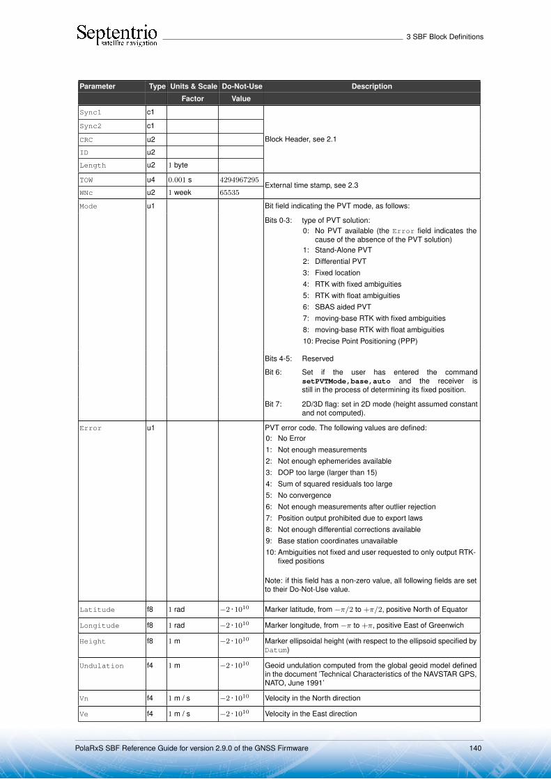
3 SBF Block Definitions
Parameter Type Units & Scale Do-Not-Use Description
Factor Value
Sync1 c1
Block Header, see 2.1
Sync2 c1
CRC u2
ID u2
Length u2 1 byte
TOW u4 0.001 s 4294967295External time stamp, see 2.3
WNc u2 1 week 65535
Mode u1 Bit field indicating the PVT mode, as follows:
Bits 0-3: type of PVT solution:0: No PVT available (the Error field indicates the
cause of the absence of the PVT solution)1: Stand-Alone PVT2: Differential PVT3: Fixed location4: RTK with fixed ambiguities5: RTK with float ambiguities6: SBAS aided PVT7: moving-base RTK with fixed ambiguities8: moving-base RTK with float ambiguities10: Precise Point Positioning (PPP)
Bits 4-5: Reserved
Bit 6: Set if the user has entered the commandsetPVTMode,base,auto and the receiver isstill in the process of determining its fixed position.
Bit 7: 2D/3D flag: set in 2D mode (height assumed constantand not computed).
Error u1 PVT error code. The following values are defined:0: No Error1: Not enough measurements2: Not enough ephemerides available3: DOP too large (larger than 15)4: Sum of squared residuals too large5: No convergence6: Not enough measurements after outlier rejection7: Position output prohibited due to export laws8: Not enough differential corrections available9: Base station coordinates unavailable10: Ambiguities not fixed and user requested to only output RTK-
fixed positions
Note: if this field has a non-zero value, all following fields are setto their Do-Not-Use value.
Latitude f8 1 rad −2 · 1010 Marker latitude, from −π/2 to +π/2, positive North of Equator
Longitude f8 1 rad −2 · 1010 Marker longitude, from −π to +π, positive East of Greenwich
Height f8 1 m −2 · 1010 Marker ellipsoidal height (with respect to the ellipsoid specified byDatum)
Undulation f4 1 m −2 · 1010 Geoid undulation computed from the global geoid model definedin the document ’Technical Characteristics of the NAVSTAR GPS,NATO, June 1991’
Vn f4 1 m / s −2 · 1010 Velocity in the North direction
Ve f4 1 m / s −2 · 1010 Velocity in the East direction
PolaRxS SBF Reference Guide for version 2.9.0 of the GNSS Firmware 140

3 SBF Block Definitions
Vu f4 1 m / s −2 · 1010 Velocity in the ’Up’ direction
COG f4 1 degree −2 · 1010 Course over ground: this is defined as the angle of the vehiclewith respect to the local level North, ranging from 0 to 360, andincreasing towards east. Set to the do-not-use value when thespeed is lower than 0.1m/s.
RxClkBias f8 1 ms −2 · 1010 Receiver clock bias relative to system time reported in theTimeSystem field. To transfer the receiver time to the systemtime, use:tGPS/GST = trx - RxClkBias
RxClkDrift f4 1 ppm −2 · 1010 Receiver clock drift relative to system time (relative frequency er-ror)
TimeSystem u1 255 Time system of which the offset is provided in this sub-block:0: GPS time1: Galileo time3: GLONASS time
Datum u1 255 This field defines in which datum the coordinates are expressed:0: WGS84/ITRS19: Datum equal to that used by the DGNSS/RTK base station30: ETRS89 (ETRF2000 realization)31: NAD83(2011), North American Datum (2011)32: NAD83(PA11), North American Datum, Pacific plate (2011)33: NAD83(MA11), North American Datum, Marianas plate
(2011)34: GDA94(2010), Geocentric Datum of Australia (2010)250: First user-defined datum251: Second user-defined datum
NrSV u1 255 Total number of satellites used in the PVT computation.
WACorrInfo u1 0 Bit field providing information about which wide area correctionshave been applied:
Bit 0: set if orbit and satellite clock correction information isused
Bit 1: set if range correction information is used
Bit 2: set if ionospheric information is used
Bit 3: set if orbit accuracy information is used (UERE/SISA)
Bit 4: set if DO229 Precision Approach mode is active
Bits 5-7: Reserved
ReferenceID u2 65535 This field indicates the reference ID of the differential informationused.In case of DGPS or RTK operation, this field is to be interpretedas the base station identifier. In SBAS operation, this field is to beinterpreted as the PRN of the geostationary satellite used (from120 to 158). If multiple base stations or multiple geostationarysatellites are used the value is set to 65534.
MeanCorrAge u2 0.01 s 65535 In case of DGPS or RTK, this field is the mean age of the differ-ential corrections.In case of SBAS operation, this field is the mean age of the ’fastcorrections’ provided by the SBAS satellites.
SignalInfo u4 0 Bit field indicating the type of GNSS signals having been used inthe PVT computations. If a bit i is set, the signal type having indexi has been used. The signal numbers are listed in section 2.10.Bit 0 (GPS-C/A) is the LSB of SignalInfo.
PolaRxS SBF Reference Guide for version 2.9.0 of the GNSS Firmware 141
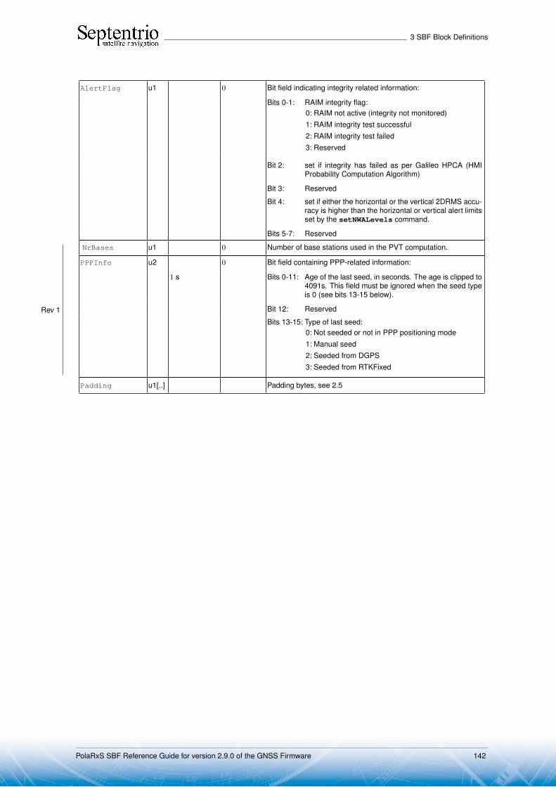
3 SBF Block Definitions
AlertFlag u1 0 Bit field indicating integrity related information:
Bits 0-1: RAIM integrity flag:0: RAIM not active (integrity not monitored)1: RAIM integrity test successful2: RAIM integrity test failed3: Reserved
Bit 2: set if integrity has failed as per Galileo HPCA (HMIProbability Computation Algorithm)
Bit 3: Reserved
Bit 4: set if either the horizontal or the vertical 2DRMS accu-racy is higher than the horizontal or vertical alert limitsset by the setNWALevels command.
Bits 5-7: Reserved
NrBases u1 0 Number of base stations used in the PVT computation.
PPPInfo u2 0 Bit field containing PPP-related information:
1 s Bits 0-11: Age of the last seed, in seconds. The age is clipped to4091s. This field must be ignored when the seed typeis 0 (see bits 13-15 below).
Bit 12: Reserved
Bits 13-15: Type of last seed:0: Not seeded or not in PPP positioning mode1: Manual seed2: Seeded from DGPS3: Seeded from RTKFixed
Rev 1
Padding u1[..] Padding bytes, see 2.5
PolaRxS SBF Reference Guide for version 2.9.0 of the GNSS Firmware 142

3 SBF Block Definitions
3.13 Differential Correction BlocksDiffCorrIn Number: 5919
"OnChange" interval: each time a RTCM or CMR message is received
The DiffCorrIn block contains incoming RTCM or CMR messages. The length of theblock depends on the message type and contents.
Parameter Type Units & Scale Do-Not-Use Description
Factor Value
Sync1 c1
Block Header, see 2.1
Sync2 c1
CRC u2
ID u2
Length u2 1 byte
TOW u4 0.001 s 4294967295Receiver time stamp, see 2.3
WNc u2 1 week 65535
Mode u1 0: RTCMv21: CMRv22: RTCMv33: RTCMV (a proprietary variant of RTCM2)
Source u1 Indicates the receiver connection from which the message hasbeen received:0: COM11: COM22: COM33: COM44: USB15: USB26: IP connection7: SBF file8: L-Band (message decoded by the built-in L-band demodu-
lator)9: NTRIP12: Bluetooth15: UHF modem16: IPR connection
If the Mode field is 0 then this field is available:
RTCM2Words u4[N] 30-bit words of the RTCM2 message. The Data Word Length(number of 32 bit words) is variable and depends on theRTCM2 message contents. It can be computed by the follow-ing piece of C code:N = 2 + ((RTCM2Words[1]»9) & 0x1f);
N can range from 2 to 33. The first two words are theRTCM2 message header and they are always present.
Each of the words is organized as follows:
Bits 0-5: 6 parity bits. They are provided for the sake of com-pleteness. Parity doesn’t need to be checked, sincethe DiffCorrIn block only contains valid words.
Bits 6-29: 24 information-containing bits of the word. The firstreceived bit is the MSB.
Bits 30-31: bit 0 and 1 of the preceding word
PolaRxS SBF Reference Guide for version 2.9.0 of the GNSS Firmware 143
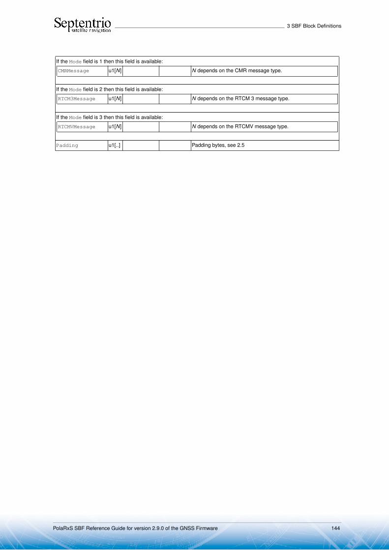
3 SBF Block Definitions
If the Mode field is 1 then this field is available:
CMRMessage u1[N] N depends on the CMR message type.
If the Mode field is 2 then this field is available:
RTCM3Message u1[N] N depends on the RTCM 3 message type.
If the Mode field is 3 then this field is available:
RTCMVMessage u1[N] N depends on the RTCMV message type.
Padding u1[..] Padding bytes, see 2.5
PolaRxS SBF Reference Guide for version 2.9.0 of the GNSS Firmware 144

3 SBF Block Definitions
BaseStation Number: 5949"OnChange" interval: block generated each time a differential correction
message related to the base station coordinates is re-ceived
The BaseStation block contains the ECEF coordinates of the base station the receiveris currently connected to. This block helps users accessing the base station coordinatesvia SBF instead of having to decode the specific differential correction message (see theDiffCorrIn SBF block above).
The interpretation to give to the X, Y, Z ECEF coordinates is dependent on the valueof the Source field:
Value of Source Interpretation of X, Y, Z
0, 4 or 10 Coordinate of the L1 phase center
2 or 8 Antenna reference point
9 Proprietary
Parameter Type Units & Scale Do-Not-Use Description
Factor Value
Sync1 c1
Block Header, see 2.1
Sync2 c1
CRC u2
ID u2
Length u2 1 byte
TOW u4 0.001 s 4294967295Receiver time stamp, see 2.3
WNc u2 1 week 65535
BaseStationID u2 The base station ID
BaseType u1 Base station type:0: Fixed1: Moving (reserved for future use)255: Unknown
Source u1 Source of the base station coordinates:0: RTCM 2.x (Msg 3)2: RTCM 2.x (Msg 24)4: CMR 2.x (Msg 1)8: RTCM 3.x (Msg 1005 or 1006)9: RTCMV (Msg 3)10: CMR+ (Type 2)
Datum u1 255 Not applicable
Reserved u1 Reserved for future use, to be ignored by decoding software
X f8 1 m Antenna X coordinate expressed in the datum specified by theDatum field
Y f8 1 m Antenna Y coordinate
Z f8 1 m Antenna Z coordinate
Padding u1[..] Padding bytes, see 2.5
PolaRxS SBF Reference Guide for version 2.9.0 of the GNSS Firmware 145

3 SBF Block Definitions
RTCMDatum Number: 4049"OnChange" interval: block generated each time a set of transformation param-
eters is received
This block reports the source and target datum names as transmitted in RTCM 3.x messagetypes 1021 or 1022. It also reports the corresponding height and quality indicators.
If a service provider only sends out message types 1021 or 1022, this block is trans-mitted immediately after reception of MT1021 or MT1022. If message types 1023 or 1024are also sent out, this block is transmitted after the reception of these messages and theQualityInd field is set accordingly.
PolaRxS SBF Reference Guide for version 2.9.0 of the GNSS Firmware 146

3 SBF Block Definitions
Parameter Type Units & Scale Do-Not-Use Description
Factor Value
Sync1 c1
Block Header, see 2.1
Sync2 c1
CRC u2
ID u2
Length u2 1 byte
TOW u4 0.001 s 4294967295Receiver time stamp, see 2.3
WNc u2 1 week 65535
SourceCRS c1[32] Name of the source Coordinate Reference System, right-paddedwith zeros.
TargetCRS c1[32] Name of the target Coordinate Reference System, right-paddedwith zeros.
Datum u1 See the Datum field in the PosLocal and PosProjected SBFblocks.
Datum is set to 255 if this SourceCRS/TargetCRS pair iscurrently not used by the receiver.
HeightType u1 Height Indicator field from MT1021 and MT1022. This fieldindicates how to interpret the marker height reported in thePosLocal and the PosProjected SBF blocks:0: Geometrical height1: Physical height (height definition in target CRS)2: Physical height (height definition in source CRS)
QualityInd u1 Bit field indicating the maximum approximation error after apply-ing the transformation:
Bits 0-3: horizontal quality indicator:0: Unknown quality1: Quality better than 21 mm (from MT1021/1022)2: Quality 21 to 50 mm (from MT1021/1022)3: Quality 51 to 200 mm (from MT1021/1022)4: Quality 201 to 500 mm (from MT1021/1022)5: Quality 501 to 2000 mm (from MT1021/1022)6: Quality 2001 to 5000 mm (from MT1021/1022)7: Quality worse than 5001 mm (from MT1021/1022)9: Quality 0 to 10 mm (from MT1023/1024)10: Quality 11 to 20 mm (from MT1023/1024)11: Quality 21 to 50 mm (from MT1023/1024)12: Quality 51 to 100 mm (from MT1023/1024)13: Quality 101 to 200 mm (from MT1023/1024)14: Quality 201 to 500 mm (from MT1023/1024)15: Quality worse than 501 mm (from MT1023/1024)
Bits 4-7: vertical quality indicator, same definition as bits 0-3.
Padding u1[..] Padding bytes, see 2.5
PolaRxS SBF Reference Guide for version 2.9.0 of the GNSS Firmware 147
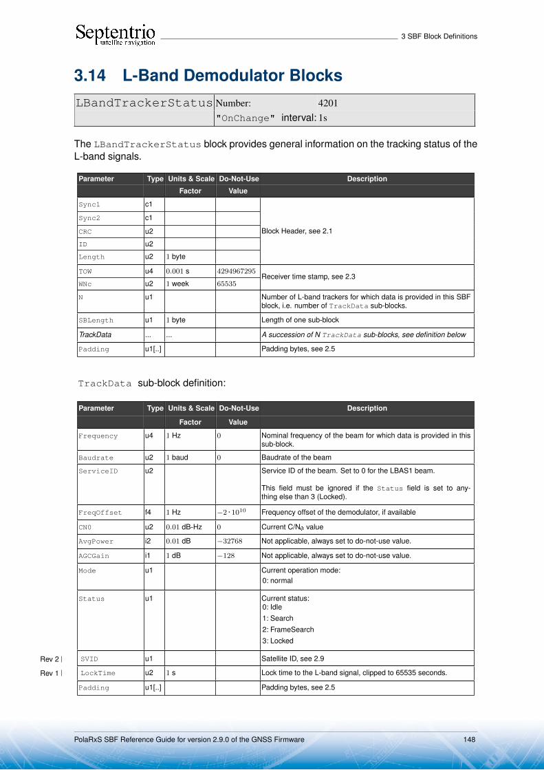
3 SBF Block Definitions
3.14 L-Band Demodulator BlocksLBandTrackerStatus Number: 4201
"OnChange" interval: 1s
The LBandTrackerStatus block provides general information on the tracking status of theL-band signals.
Parameter Type Units & Scale Do-Not-Use Description
Factor Value
Sync1 c1
Block Header, see 2.1
Sync2 c1
CRC u2
ID u2
Length u2 1 byte
TOW u4 0.001 s 4294967295Receiver time stamp, see 2.3
WNc u2 1 week 65535
N u1 Number of L-band trackers for which data is provided in this SBFblock, i.e. number of TrackData sub-blocks.
SBLength u1 1 byte Length of one sub-block
TrackData ... ... A succession of N TrackData sub-blocks, see definition below
Padding u1[..] Padding bytes, see 2.5
TrackData sub-block definition:
Parameter Type Units & Scale Do-Not-Use Description
Factor Value
Frequency u4 1 Hz 0 Nominal frequency of the beam for which data is provided in thissub-block.
Baudrate u2 1 baud 0 Baudrate of the beam
ServiceID u2 Service ID of the beam. Set to 0 for the LBAS1 beam.
This field must be ignored if the Status field is set to any-thing else than 3 (Locked).
FreqOffset f4 1 Hz −2 · 1010 Frequency offset of the demodulator, if available
CN0 u2 0.01 dB-Hz 0 Current C/N0 value
AvgPower i2 0.01 dB −32768 Not applicable, always set to do-not-use value.
AGCGain i1 1 dB −128 Not applicable, always set to do-not-use value.
Mode u1 Current operation mode:0: normal
Status u1 Current status:0: Idle1: Search2: FrameSearch3: Locked
SVID u1 Satellite ID, see 2.9Rev 2
LockTime u2 1 s Lock time to the L-band signal, clipped to 65535 seconds.Rev 1
Padding u1[..] Padding bytes, see 2.5
PolaRxS SBF Reference Guide for version 2.9.0 of the GNSS Firmware 148
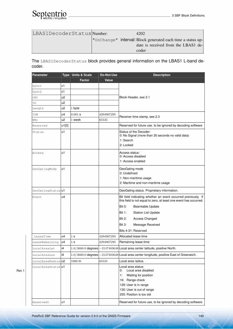
3 SBF Block Definitions
LBAS1DecoderStatus Number: 4202"OnChange" interval: Block generated each time a status up-
date is received from the LBAS1 de-coder
The LBAS1DecoderStatus block provides general information on the LBAS1 L-band de-coder.
Parameter Type Units & Scale Do-Not-Use Description
Factor Value
Sync1 c1
Block Header, see 2.1
Sync2 c1
CRC u2
ID u2
Length u2 1 byte
TOW u4 0.001 s 4294967295Receiver time stamp, see 2.3
WNc u2 1 week 65535
Reserved u1[2] Reserved for future use. to be ignored by decoding software
Status u1 Status of the Decoder:0: No Signal (more than 30 seconds no valid data)1: Search2: Locked
Access u1 Access status:0: Access disabled1: Access enabled
GeoGatingMode u1 GeoGating mode0: Undefined1: Non-maritime usage2: Maritime and non-maritime usage
GeoGatingStatus u1 GeoGating status. Proprietary information.
Event u4 Bit field indicating whether an event occurred previously. Ifthis field is not equal to zero, at least one event has occurred.
Bit 0: Beamtable Update
Bit 1: Station List Update
Bit 2: Access Changed
Bit 3: Message Received
Bits 4-31: Reserved
Rev 1
LeaseTime u4 1 s 4294967295 Allocated lease time
LeaseRemaining u4 1 s 4294967295 Remaining lease time
LocalAreaLat i4 1.0/3600.0 degrees −2147483648 Local area center latitude, positive North.
LocalAreaLon i4 1.0/3600.0 degrees −2147483648 Local area center longitude, positive East of Greenwich.
LocalAreaRadius u2 1000 m 65535 Local area radius.
LocalAreaStatus u1 Local area status:0: Local area disabled1: Waiting for position16: Range check129: User is in range130: User is out of range255: Position is too old
Reserved1 u1 Reserved for future use, to be ignored by decoding software.
PolaRxS SBF Reference Guide for version 2.9.0 of the GNSS Firmware 149

3 SBF Block Definitions
SubscrEndYear i1 1 year −128 Subscription end date, year (2 digits). From 0 to 99.
SubscrEndMonth i1 1 month −128 Subscription end date, month. From 1 to 12.
SubscrEndDay i1 1 day −128 Subscription end date, day. From 1 to 31.
SubscrEndHour i1 1 hour −128 Subscription end date, hour (UTC). From 0 to 23.
PAC c1[20] Product activation code, right padded with zeros.
Rev 1
Padding u1[..] Padding bytes, see 2.5
PolaRxS SBF Reference Guide for version 2.9.0 of the GNSS Firmware 150

3 SBF Block Definitions
LBAS1Messages Number: 4203
"OnChange" interval: Block generated each time an over-the-air mes-sage is received by the LBAS1 decoder
The LBAS1Messages block contains the over-the-air message decoded from LBAS1.
Parameter Type Units & Scale Do-Not-Use Description
Factor Value
Sync1 c1
Block Header, see 2.1
Sync2 c1
CRC u2
ID u2
Length u2 1 byte
TOW u4 0.001 s 4294967295Receiver time stamp, see 2.3
WNc u2 1 week 65535
MessageLength u2 1 byte Length of the message in this block.Maximum message length is 512 bytes
Message c1[MessageLength] Over-The-Air message
Padding u1[..] Padding bytes, see 2.5
PolaRxS SBF Reference Guide for version 2.9.0 of the GNSS Firmware 151

3 SBF Block Definitions
LBandBeams Number: 4204"OnChange" interval: Block generated each time beam status data is received
from the LBAS1 decoder
This block contains the name, longitude and beam frequency of the L-band geostationarysatellites known by the receiver.
Parameter Type Units & Scale Do-Not-Use Description
Factor Value
Sync1 c1
Block Header, see 2.1
Sync2 c1
CRC u2
ID u2
Length u2 1 byte
TOW u4 0.001 s 4294967295Receiver time stamp, see 2.3
WNc u2 1 week 65535
N u1 Number of L-band beams for which data is provided in this SBFblock, i.e. number of BeamInfo sub-blocks.
SBLength u1 1 byte Length of one sub-block
BeamInfo ... ... A succession of N BeamInfo sub-blocks, see definition below
Padding u1[..] Padding bytes, see 2.5
BeamInfo sub-block definition:
Parameter Type Units & Scale Do-Not-Use Description
Factor Value
SVID u1 SVID associated to the satellite for which information is providedin this sub-block. SVID ranges from 107 to 119. See also section2.9.
SatName c1[9] Satellite Name, right padded with zeros
SatLongitude i2 0.01 degrees −32768 Satellite Longitude (positive east of Greenwich)
BeamFreq u4 1 Hz 0 L-band beam center frequency
Padding u1[..] Padding bytes, see 2.5
PolaRxS SBF Reference Guide for version 2.9.0 of the GNSS Firmware 152

3 SBF Block Definitions
3.15 Status BlocksChannelStatus Number: 4013
"OnChange" interval: 10 ms
This block describes the current satellite allocation and tracking status of the active receiverchannels. Active channels are channels to which a satellite has been allocated.
This block uses a two-level sub-block structure analogous to that of the MeasEpoch block.For each active channel, a ChannelSatInfo sub-block contains all satellite-dependentinformation such as health, azimuth and elevation. Each of these sub-blocks contains N2ChannelStateInfo sub-blocks, N2 being the number of active antennas in a given chan-nel (for single-antenna receivers, N2 is one). The ChannelStateInfo reports informationsuch as the tracking status and PVT usage of a given signal type tracked on a given antenna.
Inactive channels are not contained in the ChannelStatus block.
Health, tracking and PVT status fields are available for each satellite. These statusfields consist of a sequence of up to 8 two-bit fields. Each 2-bit field contains the status ofone of the signals transmitted by the satellite. The position of the 2 bits corresponding to agiven signal is dependent on the constellation, but is otherwise fixed. It is indicated in thetables below.
GPS:Reserved Reserved Reserved L5 L2C P2(Y) P1(Y) L1CA
15 14 13 12 11 10 9 8 7 6 5 4 3 2 1 0
GLONASS:Reserved Reserved Reserved L3 L2CA L2P Reserved L1CA
15 14 13 12 11 10 9 8 7 6 5 4 3 2 1 0
Galileo:Reserved E5-AltBOC E5b E5a E6BC E6A L1BC L1A
15 14 13 12 11 10 9 8 7 6 5 4 3 2 1 0
SBAS:Reserved Reserved Reserved Reserved Reserved Reserved L5 L1
15 14 13 12 11 10 9 8 7 6 5 4 3 2 1 0
COMPASS/BEIDOU:Reserved Reserved Reserved Reserved Reserved B3 B2 B1
15 14 13 12 11 10 9 8 7 6 5 4 3 2 1 0
QZSS:Reserved Reserved Reserved Reserved Reserved L5 L2C L1CA
15 14 13 12 11 10 9 8 7 6 5 4 3 2 1 0
IRNSS:Reserved Reserved Reserved Reserved Reserved Reserved Reserved L5
15 14 13 12 11 10 9 8 7 6 5 4 3 2 1 0
PolaRxS SBF Reference Guide for version 2.9.0 of the GNSS Firmware 153

3 SBF Block Definitions
Parameter Type Units & Scale Do-Not-Use Description
Factor Value
Sync1 c1
Block Header, see 2.1
Sync2 c1
CRC u2
ID u2
Length u2 1 byte
TOW u4 0.001 s 4294967295Receiver time stamp, see 2.3
WNc u2 1 week 65535
N u1 Number of channels for which status are provided in this SBFblock, i.e. number of ChannelSatInfo sub-blocks. If N is 0,there are no active channels available for this epoch.
SB1Length u1 1 byte Length of a ChannelSatInfo sub-block, excluding the nestedChannelStateInfo sub-blocks
SB2Length u1 1 byte Length of a ChannelStateInfo sub-block
Reserved u1[3] Reserved for future use, to be ignored by decoding software
SatInfo ... ... A succession of N ChannelSatInfo sub-blocks, see definitionbelow
Padding u1[..] Padding bytes, see 2.5
ChannelSatInfo sub-block definition:
Parameter Type Units & Scale Do-Not-Use Description
Factor Value
SVID u1 Satellite ID, see 2.9
FreqNr u1 0 For GLONASS satellites, this is the frequency number, with anoffset of 8. It ranges from 1 (corresponding to an actual frequencynumber of -7) to 21 (corresponding to an actual frequency numberof 13). For non-GLONASS satellites, FreqNr is reserved andmust be ignored by the decoding software.
Reserved1 u1[2] Reserved for future use, to be ignored by decoding software
Azimuth/RiseSet u2 bit field:
1 degree 511 Bits 0-8: Azimuth [0,359]. 0 is North, and Azimuth increasestowards East.
Bits 9-13: Reserved
3 Bits 14-15: Rise/Set Indicator:0: Satellite setting1: Satellite rising3: Elevation rate unknown
HealthStatus u2 Sequence of 2-bit health status fields, each of them taking one ofthe following values:0 : health unknown, or not applicable1 : healthy3 : unhealthy
The 2-bit health status is a condensed version of the healthstatus as sent by the satellite. For SBAS, the health status is setfrom the almanac data (MT17).
Elevation i1 1 degree −128 Elevation [-90,90] relative to local horizontal plane
N2 u1 Number of ChannelStateInfo blocks following thisChannelSatInfo block. There is one ChannelStateInfosub-block per antenna.
RxChannel u1 Channel number, see section 2.11.
PolaRxS SBF Reference Guide for version 2.9.0 of the GNSS Firmware 154
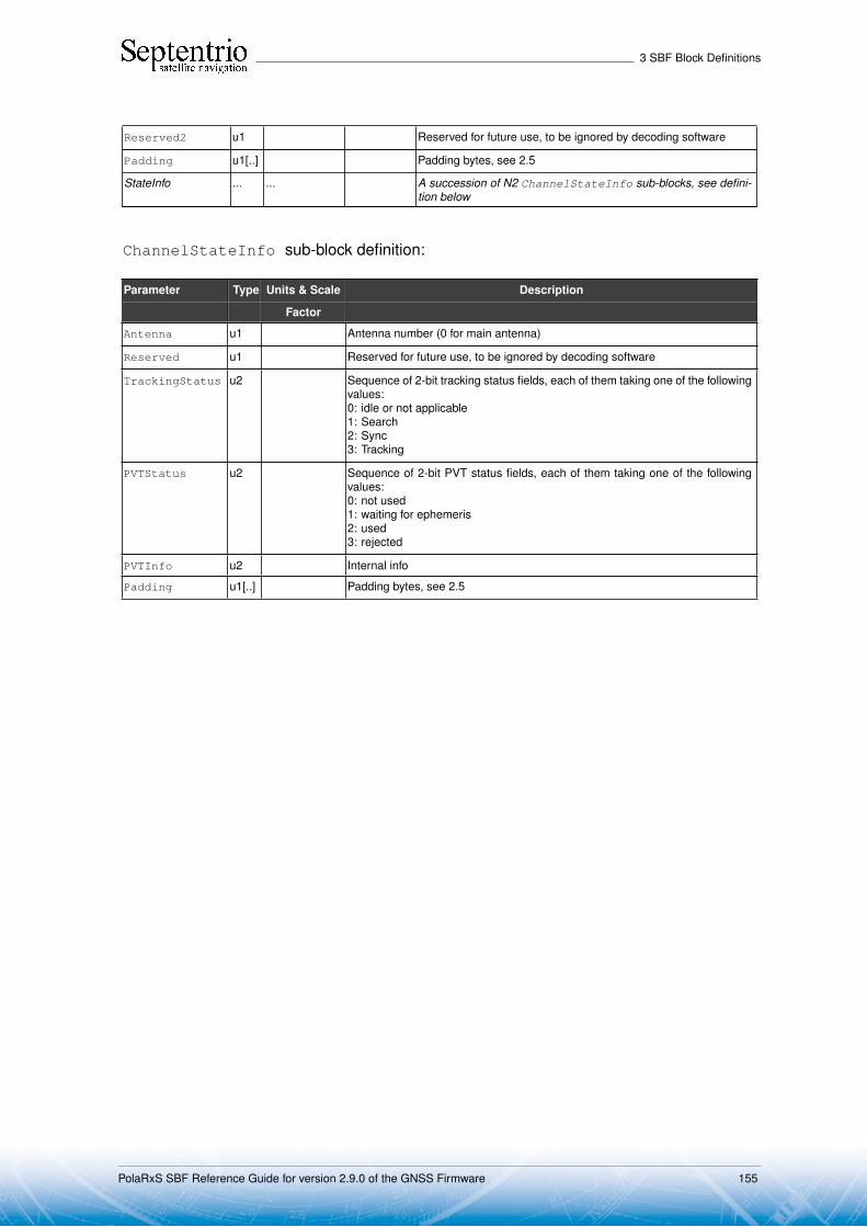
3 SBF Block Definitions
Reserved2 u1 Reserved for future use, to be ignored by decoding software
Padding u1[..] Padding bytes, see 2.5
StateInfo ... ... A succession of N2 ChannelStateInfo sub-blocks, see defini-tion below
ChannelStateInfo sub-block definition:
Parameter Type Units & Scale Description
Factor
Antenna u1 Antenna number (0 for main antenna)
Reserved u1 Reserved for future use, to be ignored by decoding software
TrackingStatus u2 Sequence of 2-bit tracking status fields, each of them taking one of the followingvalues:0: idle or not applicable1: Search2: Sync3: Tracking
PVTStatus u2 Sequence of 2-bit PVT status fields, each of them taking one of the followingvalues:0: not used1: waiting for ephemeris2: used3: rejected
PVTInfo u2 Internal info
Padding u1[..] Padding bytes, see 2.5
PolaRxS SBF Reference Guide for version 2.9.0 of the GNSS Firmware 155

3 SBF Block Definitions
ReceiverStatus Number: 4014"OnChange" interval: 1s
The ReceiverStatus block provides general information on the status of the re-ceiver.
Parameter Type Units & Scale Do-Not-Use Description
Factor Value
Sync1 c1
Block Header, see 2.1
Sync2 c1
CRC u2
ID u2
Length u2 1 byte
TOW u4 0.001 s 4294967295Receiver time stamp, see 2.3
WNc u2 1 week 65535
CPULoad u1 1 % 255 Load on the receiver’s CPU. The load should stay below 80% innormal operation. Higher loads might result in data loss.
ExtError u1 Bit field reporting external errors, i.e. errors detected in externaldata. Upon detection of an error, the corresponding bit is set fora duration of one second, and then resets.
Bit 0: SISERROR: set if a violation of the signal-in-spaceICD has been detected for at least one satellite whilethat satellite is reported as healthy. Use the command"lif,SisError" for details.
Bit 1: DIFFCORRERROR: set when an anomaly has beendetected in an incoming differential correction stream,causing the receiver to fail to decode the corrections.Use the command "lif,DiffCorrError" for de-tails.
Bit 2: EXTSENSORERROR: set when a malfunction hasbeen detected on at least one of the external sensorsconnected to the receiver. Use the command "lif,ExtSensorError" for details.
Bit 3: SETUPERROR: set when a configuration/setup errorhas been detected. An example of such error is whena remote NTRIP Caster is not reachable. Use the com-mand "lif, SetupError" for details.
Bits 4-7: Reserved
UpTime u4 1 s Number of seconds elapsed since the start-up of the receiver, orsince the last reset.
PolaRxS SBF Reference Guide for version 2.9.0 of the GNSS Firmware 156
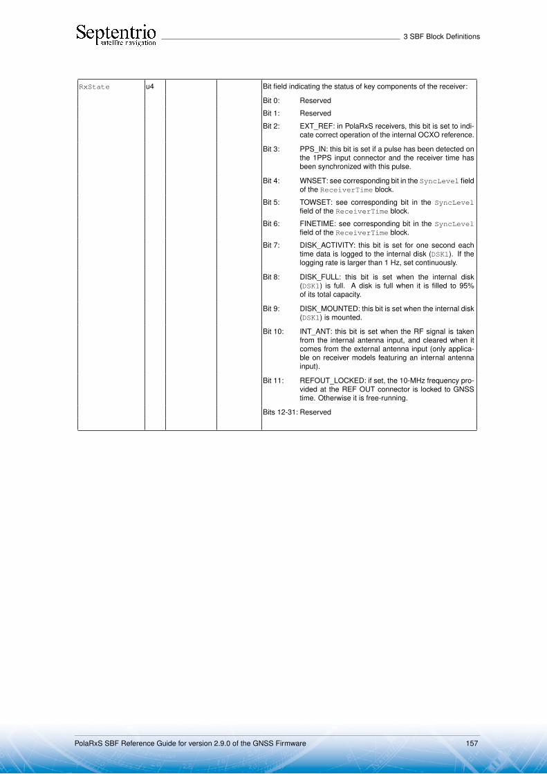
3 SBF Block Definitions
RxState u4 Bit field indicating the status of key components of the receiver:
Bit 0: Reserved
Bit 1: Reserved
Bit 2: EXT_REF: in PolaRxS receivers, this bit is set to indi-cate correct operation of the internal OCXO reference.
Bit 3: PPS_IN: this bit is set if a pulse has been detected onthe 1PPS input connector and the receiver time hasbeen synchronized with this pulse.
Bit 4: WNSET: see corresponding bit in the SyncLevel fieldof the ReceiverTime block.
Bit 5: TOWSET: see corresponding bit in the SyncLevelfield of the ReceiverTime block.
Bit 6: FINETIME: see corresponding bit in the SyncLevelfield of the ReceiverTime block.
Bit 7: DISK_ACTIVITY: this bit is set for one second eachtime data is logged to the internal disk (DSK1). If thelogging rate is larger than 1 Hz, set continuously.
Bit 8: DISK_FULL: this bit is set when the internal disk(DSK1) is full. A disk is full when it is filled to 95%of its total capacity.
Bit 9: DISK_MOUNTED: this bit is set when the internal disk(DSK1) is mounted.
Bit 10: INT_ANT: this bit is set when the RF signal is takenfrom the internal antenna input, and cleared when itcomes from the external antenna input (only applica-ble on receiver models featuring an internal antennainput).
Bit 11: REFOUT_LOCKED: if set, the 10-MHz frequency pro-vided at the REF OUT connector is locked to GNSStime. Otherwise it is free-running.
Bits 12-31: Reserved
PolaRxS SBF Reference Guide for version 2.9.0 of the GNSS Firmware 157

3 SBF Block Definitions
RxError u4 Bit field indicating whether an error occurred previously. If thisfield is not equal to zero, at least one error has been detected.
Bit 0: Reserved
Bit 1: Reserved
Bit 2: Reserved
Bit 3: SOFTWARE: set upon detection of a software warn-ing or error. This bit is reset by the command "lif,error".
Bit 4: WATCHDOG: set when the watchdog expired at leastonce since the last power-on.
Bit 5: Reserved
Bit 6: CONGESTION: set when an output data congestionhas been detected on at least one of the communica-tion ports of the receiver during the last second.
Bit 7: Reserved
Bit 8: MISSEDEVENT: set when an external event conges-tion has been detected during the last second. It indi-cates that the receiver is receiving too many events onits EVENTx pins.
Bit 9: CPUOVERLOAD: set when the CPU load is largerthan 90%. If this bit is set, receiver operation maybe unreliable and the user must decrease the pro-cessing load by following the recommendations in theFirmware User Manual.
Bit 10: INVALIDCONFIG: set if one or more configuration file(e.g. permissions) is invalid or absent.
Bit 11: OUTOFGEOFENCE: set if the receiver is currently outof its permitted region of operation (geofencing).
Bit 12: Reserved for future use
Bit 13: Reserved for future use
Bit 14: Reserved for future use
Bit 15: Reserved for future use
Bit 16: Reserved for future use
Rev 1
Bits 17-31: Reserved
N u1 Number of AGCState sub-blocks this block contains.
SBLength u1 1 byte Length of a AGCState sub-block.
CmdCount u1 0 Command cyclic counter, incremented each time a command isentered that changes the receiver configuration. After the counterhas reached 255, it resets to 1.
Temperature u1 1 ◦C 0 Not applicable.
AGCState ... ... A succession of N AGCState sub-blocks, see definition below
Padding u1[..] Padding bytes, see 2.5
PolaRxS SBF Reference Guide for version 2.9.0 of the GNSS Firmware 158
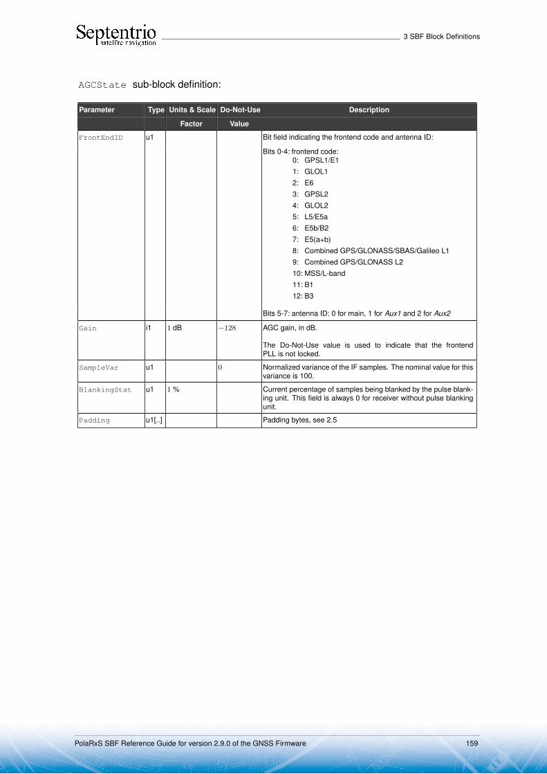
3 SBF Block Definitions
AGCState sub-block definition:
Parameter Type Units & Scale Do-Not-Use Description
Factor Value
FrontEndID u1 Bit field indicating the frontend code and antenna ID:
Bits 0-4: frontend code:0: GPSL1/E11: GLOL12: E63: GPSL24: GLOL25: L5/E5a6: E5b/B27: E5(a+b)8: Combined GPS/GLONASS/SBAS/Galileo L19: Combined GPS/GLONASS L210: MSS/L-band11: B112: B3
Bits 5-7: antenna ID: 0 for main, 1 for Aux1 and 2 for Aux2
Gain i1 1 dB −128 AGC gain, in dB.
The Do-Not-Use value is used to indicate that the frontendPLL is not locked.
SampleVar u1 0 Normalized variance of the IF samples. The nominal value for thisvariance is 100.
BlankingStat u1 1 % Current percentage of samples being blanked by the pulse blank-ing unit. This field is always 0 for receiver without pulse blankingunit.
Padding u1[..] Padding bytes, see 2.5
PolaRxS SBF Reference Guide for version 2.9.0 of the GNSS Firmware 159

3 SBF Block Definitions
SatVisibility Number: 4012
"OnChange" interval: 1s
This block contains the azimuth and elevation of all the satellites above the horizon for whichthe ephemeris or almanac is available.
Parameter Type Units & Scale Do-Not-Use Description
Factor Value
Sync1 c1
Block Header, see 2.1
Sync2 c1
CRC u2
ID u2
Length u2 1 byte
TOW u4 0.001 s 4294967295Receiver time stamp, see 2.3
WNc u2 1 week 65535
N u1 Number of satellites for which information is provided in this SBFblock, i.e. number of SatInfo sub-blocks.
SBLength u1 1 byte Length of one SatInfo sub-block
SatInfo ... ... A succession of N SatInfo sub-blocks, see definition below
Padding u1[..] Padding bytes, see 2.5
SatInfo sub-block definition:
Parameter Type Units & Scale Do-Not-Use Description
Factor Value
SVID u1 Satellite ID, see 2.9
FreqNr u1 0 For GLONASS satellites, this is the frequency number, with anoffset of 8. It ranges from 1 (corresponding to an actual frequencynumber of -7) to 21 (corresponding to an actual frequency numberof 13). For non-GLONASS satellites, FreqNr is reserved andmust be ignored by the decoding software.
Azimuth u2 0.01 degrees 65535 Azimuth. 0 is North, and azimuth increases towards East.
Elevation i2 0.01 degrees −32768 Elevation relative to local horizontal plane.
RiseSet u1 Rise/set indicator:0: satellite setting1: satellite rising255: elevation rate unknown
SatelliteInfo u1 Satellite visibility info based on:1: almanac2: ephemeris255: unknown
Padding u1[..] Padding bytes, see 2.5
PolaRxS SBF Reference Guide for version 2.9.0 of the GNSS Firmware 160

3 SBF Block Definitions
InputLink Number: 4090
"OnChange" interval: 1s
The InputLink block reports statistics of the number of bytes and messages received andaccepted on each active connection descriptor.
Per connection descriptor, the receiver maintains two byte counters (NrBytesReceivedand NrBytesAccepted) and two message counters (NrMsgReceived andNrMsgAccepted), which are reported in the sub-blocks. These counters provideuseful information on the quality of the transmission link, and of the bandwidth efficiency.
These counters (as well as the age of the last message) are reset simultaneously onthe following events:
• start-up of the receiver• overflow of one of the counters• change of input type• deactivation of a connection descriptor, e.g. on disconnection of USB or IP ports.
There is one sub-block per connection descriptor for which statistics is available.
Parameter Type Units & Scale Do-Not-Use Description
Factor Value
Sync1 c1
Block Header, see 2.1
Sync2 c1
CRC u2
ID u2
Length u2 1 byte
TOW u4 0.001 s 4294967295Receiver time stamp, see 2.3
WNc u2 1 week 65535
N u1 Number of connection descriptors for which communication linkstatistics are included
SBLength u1 1 byte Length of one InputStatsSub sub-block.
InputStats ... ... A succession of N InputStatsSub sub-blocks, see definitionbelow
Padding u1[..] Padding bytes, see 2.5
PolaRxS SBF Reference Guide for version 2.9.0 of the GNSS Firmware 161

3 SBF Block Definitions
InputStatsSub sub-block definition:
Parameter Type Units & Scale Do-Not-Use Description
Factor Value
CD u1 Identifier of the connection to which these statistics apply:
Value of Connection type Example
CD
0-31 COMx, with x=CD 1: COM1
32-63 USBx, with x=CD-32 33: USB1
64-95 IPx, with x=CD-54 64:IP10
96-127 DSKx, with x=CD-96 97:DSK1
128-159 NTRx, with x=CD-128 (NTRIP connec-tions)
129:NTR1
160-191 IPSx, with x=CD-160 (IP server connec-tions)
161:IPS1
192 BT01 (Bluetooth connection)
196 UHF1 (UHF Modem)
200-205 IPRx, with x=CD-200 (IP receive connec-tions)
201:IPR1
206-255 Reserved
Type u1 Type of data:0: none1: DaisyChain (includes "echo" messages)32: CMD33: SBF34: AsciiDisplay (see setDataInOut command)64: NMEA96: RTCMv297: RTCMv398: CMRv299: RTCMV (a proprietary variant of RTCMv2)128: MTI (IMU sensor)129: MMQ (IMU sensor)130: ELLIPSE (IMU sensor)160: ASCIIIn
AgeOfLastMessage u2 1 s 65535 Age of the last accepted message.
If the age is older than 65534s, it is clipped to 65534s.
NrBytesReceived u4 1 byte Total number of bytes received (10)
NrBytesAccepted u4 1 byte 4294967295 Total number of bytes (10) in messages that passed the check forthis type of input (CRC, parity check, ...).
The ratio of NrBytesAccepted to NrBytesReceivedgives an indication of the quality of the communication link.
NrMsgReceived u4 1 message 4294967295 Total number of messages of type Type received.
(10) Note that, for RTCM 2.x, one 8-bit byte contains 6 RTCM data bits.
PolaRxS SBF Reference Guide for version 2.9.0 of the GNSS Firmware 162
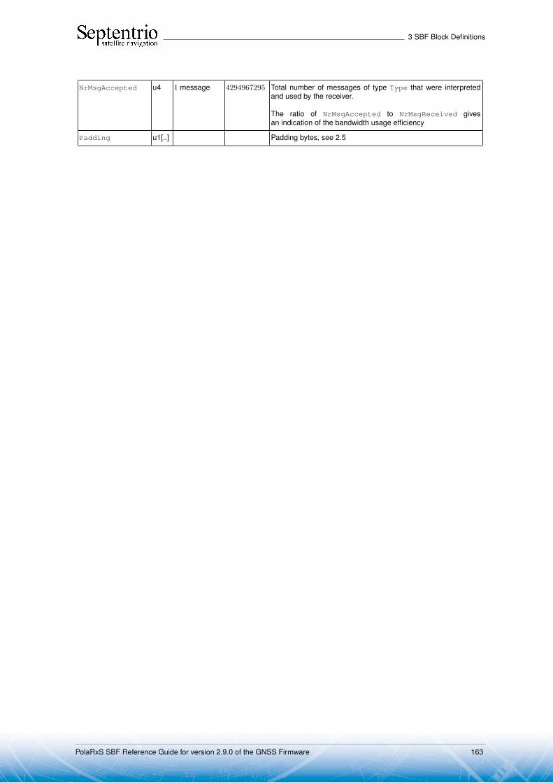
3 SBF Block Definitions
NrMsgAccepted u4 1 message 4294967295 Total number of messages of type Type that were interpretedand used by the receiver.
The ratio of NrMsgAccepted to NrMsgReceived givesan indication of the bandwidth usage efficiency
Padding u1[..] Padding bytes, see 2.5
PolaRxS SBF Reference Guide for version 2.9.0 of the GNSS Firmware 163

3 SBF Block Definitions
OutputLink Number: 4091
"OnChange" interval: 1s
The OutputLink block reports statistics of the number of bytes sent on each activeconnection descriptor.
Per connection descriptor, the receiver maintains two byte counters NrBytesProducedand NrBytesSent, which are reported in the sub-block. They provide an indication of theamount of data output and data lost on a given connection.
These counters are reset simultaneously on the following events:
• start-up of the receiver• overflow of one of the counters• deactivation of a connection descriptor, e.g. on disconnection of USB or IP ports• change of COM port settings.
There is one OutputStatsSub sub-block per connection descriptor for which statistics isavailable. Each OutputStatsSub sub-block contains a number of OutputTypeSub sub-blocks. These sub-blocks indicate which data type has been output through the connectionin question during the last second. If no output happened during the last second, there is noOutputTypeSub sub-block.
Parameter Type Units & Scale Do-Not-Use Description
Factor Value
Sync1 c1
Block Header, see 2.1
Sync2 c1
CRC u2
ID u2
Length u2 1 byte
TOW u4 0.001 s 4294967295Receiver time stamp, see 2.3
WNc u2 1 week 65535
N1 u1 Number of OutputStatsSub sub-blocks in this OutputLinkblock.
SB1Length u1 1 byte Length of an OutputStatsSub sub-block, excluding the nestedOutputTypeSub sub-block
SB2Length u1 1 byte Length of an OutputTypeSub sub-block
Reserved u1[3] Reserved for future use
OutputStats ... ... A succession of N1 OutputStatsSub sub-blocks, see definitionbelow
Padding u1[..] Padding bytes, see 2.5
PolaRxS SBF Reference Guide for version 2.9.0 of the GNSS Firmware 164

3 SBF Block Definitions
OutputStatsSub sub-block definition:
Parameter Type Units & Scale Description
Factor
CD u1 Identifier of the connection to which these statistics apply:
Value of Connection type Example
CD
0-31 COMx, with x=CD 1: COM1
32-63 USBx, with x=CD-32 33: USB1
64-95 IPx, with x=CD-54 64:IP10
96-127 DSKx, with x=CD-96 97:DSK1
128-159 NTRx, with x=CD-128 (NTRIP connections) 129:NTR1
160-191 IPSx, with x=CD-160 (IP server connections) 161:IPS1
192 BT01 (Bluetooth connection)
196 UHF1 (UHF Modem)
200-205 IPRx, with x=CD-200 (IP receive connections) 201:IPR1
206-255 Reserved
N2 u1 Number of OutputTypeSub sub-blocks included at the end of thisOutputStatsSub sub-block
AllowedRate u2 1 kbyte / s Maximum datarate recommended on this connection
NrBytesProduced u4 1 byte Total number of bytes produced by the receiver
NrBytesSent u4 1 byte Total number of bytes actually sent (i.e. without congestions or transmissionerrors).
The ratio of NrBytesSent to NrBytesProduced gives an indication ofthe amount of bandwidth overload.
NrClients u1 Number of clients currently connected to this connection. Most connectiontypes can only serve one client at a time, but each IP server (IPS) port canserve up to eight simultaneous clients.
Note that when NrClients is more than one, the fields NrBytesProducedand NrBytesSent are the total number of bytes produced and sent to allclient.
Reserved u1[3] Reserved for future use
Rev 1
Padding u1[..] Padding bytes, see 2.5
OutputType ... ... A succession of N2 OutputTypeSub sub-blocks, see definition below
PolaRxS SBF Reference Guide for version 2.9.0 of the GNSS Firmware 165

3 SBF Block Definitions
OutputTypeSub sub-block definition:
Parameter Type Units & Scale Description
Factor
Type u1 Type of data:0: none1: DaisyChain (includes "echo" messages)32: CMD33: SBF34: AsciiDisplay (see setDataInOut command)64: NMEA96: RTCMv297: RTCMv398: CMRv299: RTCMV (a proprietary variant of RTCMv2)128: MTI (IMU sensor)129: MMQ (IMU sensor)130: ELLIPSE (IMU sensor)160: ASCIIIn
Percentage u1 1 % Percentage of the produced bytes that belong to this type (during the last sec-ond)
Padding u1[..] Padding bytes, see 2.5
PolaRxS SBF Reference Guide for version 2.9.0 of the GNSS Firmware 166

3 SBF Block Definitions
NTRIPClientStatus Number: 4053"OnChange" interval: 1s
This block reports the current status of the NTRIP client connections.
Parameter Type Units & Scale Do-Not-Use Description
Factor Value
Sync1 c1
Block Header, see 2.1
Sync2 c1
CRC u2
ID u2
Length u2 1 byte
TOW u4 0.001 s 4294967295Receiver time stamp, see 2.3
WNc u2 1 week 65535
N u1 Number of NTRIP client connections for which status is pro-vided in this block, i.e. number of NTRIPClientConnectionsub-blocks.
SBLength u1 1 byte Length of one NTRIPClientConnection sub-block
NTRIPClientConnection ... ... A succession of N NTRIPClientConnection sub-blocks,see definition below
Padding u1[..] Padding bytes, see 2.5
NTRIPClientConnection sub-block definition:
Parameter Type Units & Scale Description
Factor
CDIndex u1 Index of the NTRIP connection (1 for NTR1, 2 for NTR2, etc) for which status isprovided in this sub-block.
Status u1 NTRIP client status:0: Connection disabled1: Initializing2: Running, differential corrections are being received and the link statistics is
available in the InputLink block.3: Error detected, the error code is provided in the next field.4: Retrying, client encountered an error, we are retrying to connect. The error
code is provided in the next field.
ErrorCode u1 NTRIP error code:0: No error1: Initialization error (e.g. source table retrieval failure)2: Authentication error3: Connection error4: Mountpoint does not exist5: Waiting for GGA6: GGA sending disabled when required by mountpoint7: Resolving host failed254: Unknown error
Padding u1[..] Padding bytes, see 2.5
PolaRxS SBF Reference Guide for version 2.9.0 of the GNSS Firmware 167

3 SBF Block Definitions
IPStatus Number: 4058"OnChange" interval: output each time one or more IP parameters change
This block contains the receiver’s IP address, the gateway, the netmask and the MAC ad-dress.
Parameter Type Units & Scale Do-Not-Use Description
Factor Value
Sync1 c1
Block Header, see 2.1
Sync2 c1
CRC u2
ID u2
Length u2 1 byte
TOW u4 0.001 s 4294967295Receiver time stamp, see 2.3
WNc u2 1 week 65535
MACAddress u1[6] MAC address. The first byte corresponds to the MSB of theaddress.
IPAddress u1[16] All elements set to 0 IP address. For future upgradability, this field can containa 128-bit IPv6 address. In the current firmware version,the first 12 bytes are always set to 0, and the last 4 bytescontain the IPv4 IP address, or are set to zero if the IPaddress is not known or not applicable.
Gateway u1[16] All elements set to 0 Gateway address. For future upgradability, this field cancontain a 128-bit IPv6 address. In the current firmwareversion, the first 12 bytes are always set to 0, and the last4 bytes contain the IPv4 IP address, or are set to zero if thegateway address is not known or not applicable.
Netmask u1 255 Number of bits used to identify the network (CIDR nota-tion).
Padding u1[..] Padding bytes, see 2.5
PolaRxS SBF Reference Guide for version 2.9.0 of the GNSS Firmware 168
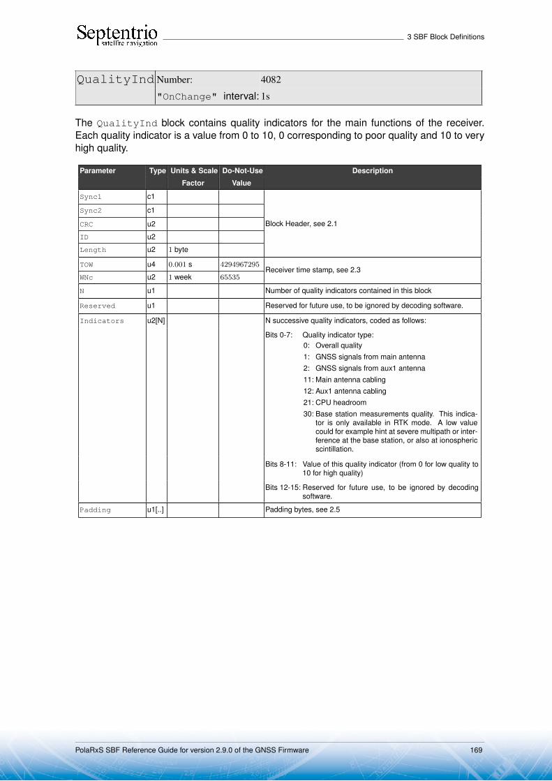
3 SBF Block Definitions
QualityInd Number: 4082
"OnChange" interval: 1s
The QualityInd block contains quality indicators for the main functions of the receiver.Each quality indicator is a value from 0 to 10, 0 corresponding to poor quality and 10 to veryhigh quality.
Parameter Type Units & Scale Do-Not-Use Description
Factor Value
Sync1 c1
Block Header, see 2.1
Sync2 c1
CRC u2
ID u2
Length u2 1 byte
TOW u4 0.001 s 4294967295Receiver time stamp, see 2.3
WNc u2 1 week 65535
N u1 Number of quality indicators contained in this block
Reserved u1 Reserved for future use, to be ignored by decoding software.
Indicators u2[N] N successive quality indicators, coded as follows:
Bits 0-7: Quality indicator type:0: Overall quality1: GNSS signals from main antenna2: GNSS signals from aux1 antenna11: Main antenna cabling12: Aux1 antenna cabling21: CPU headroom30: Base station measurements quality. This indica-
tor is only available in RTK mode. A low valuecould for example hint at severe multipath or inter-ference at the base station, or also at ionosphericscintillation.
Bits 8-11: Value of this quality indicator (from 0 for low quality to10 for high quality)
Bits 12-15: Reserved for future use, to be ignored by decodingsoftware.
Padding u1[..] Padding bytes, see 2.5
PolaRxS SBF Reference Guide for version 2.9.0 of the GNSS Firmware 169

3 SBF Block Definitions
DiskStatus Number: 4059"OnChange" interval: 1s
This block reports the size and usage of the disks mounted on the receiver.
Parameter Type Units & Scale Do-Not-Use Description
Factor Value
Sync1 c1
Block Header, see 2.1
Sync2 c1
CRC u2
ID u2
Length u2 1 byte
TOW u4 0.001 s 4294967295Receiver time stamp, see 2.3
WNc u2 1 week 65535
N u1 Number of DiskData sub-blocks this block contains.
SBLength u1 1 byte Length of one DiskData sub-blocks in bytes.
Reserved u1[4] Reserved for future use
DiskData ... ... A succession of N DiskData sub-blocks, see definition below
Padding u1[..] Padding bytes, see 2.5
DiskData sub-block definition:
Parameter Type Units & Scale Do-Not-Use Description
Factor Value
DiskID u1 ID of the disk, starting at 1 for the internal SD Memory Card.
Status u1 Bit field:
Bit 0: DISK_MOUNTED: bit set when the disk is mounted.
Bit 1: DISK_FULL: bit set when the disk is full. A disk isfull when it is filled to 95% of its total capacity.
Bit 2: DISK_ACTIVITY: bit set for one second each timedata is written to the disk. If the logging rate is largerthan 1 Hz, set continuously.
Bit 3: LOGGING_ENABLED: bit set when at least one fileis open on the disk, regardless of the logging rate.
Bits 4-7: Reserved
DiskUsageMSB u2 65535 (11) 16 MSB of the total disk usage. The disk usage in bytes isgiven by DiskUsageMSB*4294967296+DiskUsageLSB.
DiskUsageLSB u4 4294967295 (11) 32 LSB of the total disk usage. The disk usage in bytes isgiven by DiskUsageMSB*4294967296+DiskUsageLSB.
DiskSize u4 1 Mbyte 0 Total size of the disk, in megabytes.
CreateDeleteCount u1 Counter incremented by one each time a file or a folder iscreated or deleted on this disk. This counter starts at zeroat receiver start-up and restarts at zero after having reached255.
Padding u1[..] Padding bytes, see 2.5
(11) The disk usage is invalid if both DiskUsageMSB is 65535 and DiskUsageLSB is 4294967295.
PolaRxS SBF Reference Guide for version 2.9.0 of the GNSS Firmware 170

3 SBF Block Definitions
3.16 Miscellaneous BlocksReceiverSetup Number: 5902
"OnChange" interval: Block generated each time the userinvokes one of the following com-mands: setAntennaOffset,setMarkerParameters orsetObserverParameters
The ReceiverSetup block contains parameters related to the receiver set-up. This blockprovides most of the information to be included in a RINEX header.
Parameter Type Units & Scale Do-Not-Use Description
Factor Value
Sync1 c1
Block Header, see 2.1
Sync2 c1
CRC u2
ID u2
Length u2 1 byte
TOW u4 0.001 s 4294967295Receiver time stamp, see 2.3
WNc u2 1 week 65535
Reserved u1[2] 2 bytes reserved for future use, to be ignored by decoding soft-ware
MarkerName c1[60] Name of the marker, this is a 60-character string, right paddedwith zeros.
MarkerNumber c1[20] Marker identification, this is a 20-character string, right paddedwith zeros
Observer c1[20] Observer description, this is a 20-character string, right paddedwith zeros.
Agency c1[40] Observer’s agency description, this is a 40-character string, rightpadded with zeros
RxSerialNumber c1[20] Receiver serial number, this is a 20-character string, right paddedwith zeros.
RxName c1[20] Receiver core name, this is a 20-character string, right paddedwith zeros.
RxVersion c1[20] Receiver firmware version, this is a 20-character string, rightpadded with zeros.
AntSerialNbr c1[20] Serial number of the main antenna, this is a 20-character string,right padded with zeros.
AntType c1[20] Type of the main antenna, this is a 20-character string, rightpadded with zeros
deltaH f4 1 m δH offset of the main antenna
deltaE f4 1 m δE offset of the main antenna
deltaN f4 1 m δN offset of the main antenna
MarkerType c1[20] Marker type, this is a 20-character string, right padded with zerosRev 1
GNSSFWVersion c1[40] Version tag of the GNSS firmware installed on the receiver. Thisis a 40-character string, right padded with zeros.Rev 2
ProductName c1[40] Product name. This is a 40-character string, right padded withzeros.Rev 3
Padding u1[..] Padding bytes, see 2.5
PolaRxS SBF Reference Guide for version 2.9.0 of the GNSS Firmware 171

3 SBF Block Definitions
Commands Number: 4015"OnChange" interval: each time a user command is entered
Every time the user sends a command, a Commands block is output on all ports for whichthis block is enabled. The Commands SBF block is inserted in the SBF stream at the verymoment when the command starts to take effect.
Parameter Type Units & Scale Do-Not-Use Description
Factor Value
Sync1 c1
Block Header, see 2.1
Sync2 c1
CRC u2
ID u2
Length u2 1 byte
TOW u4 0.001 s 4294967295Receiver time stamp, see 2.3
WNc u2 1 week 65535
Reserved u1[2] Reserved for future use, to be ignored by decoding software.
CmdData u1[N] Command data, this is the command in the SNMP’ format (re-served for maintenance and support only).
Padding u1[..] Padding bytes, see 2.5
PolaRxS SBF Reference Guide for version 2.9.0 of the GNSS Firmware 172
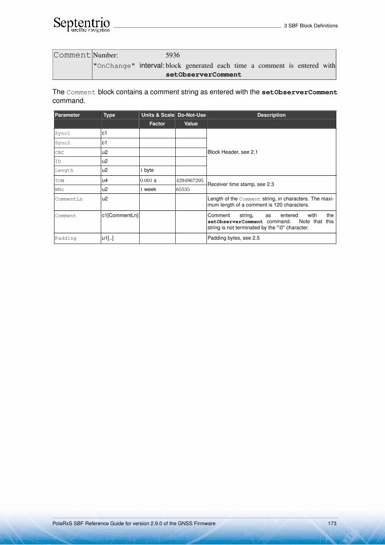
3 SBF Block Definitions
Comment Number: 5936"OnChange" interval: block generated each time a comment is entered with
setObserverComment
The Comment block contains a comment string as entered with the setObserverCommentcommand.
Parameter Type Units & Scale Do-Not-Use Description
Factor Value
Sync1 c1
Block Header, see 2.1
Sync2 c1
CRC u2
ID u2
Length u2 1 byte
TOW u4 0.001 s 4294967295Receiver time stamp, see 2.3
WNc u2 1 week 65535
CommentLn u2 Length of the Comment string, in characters. The maxi-mum length of a comment is 120 characters.
Comment c1[CommentLn] Comment string, as entered with thesetObserverComment command. Note that thisstring is not terminated by the "\0" character.
Padding u1[..] Padding bytes, see 2.5
PolaRxS SBF Reference Guide for version 2.9.0 of the GNSS Firmware 173
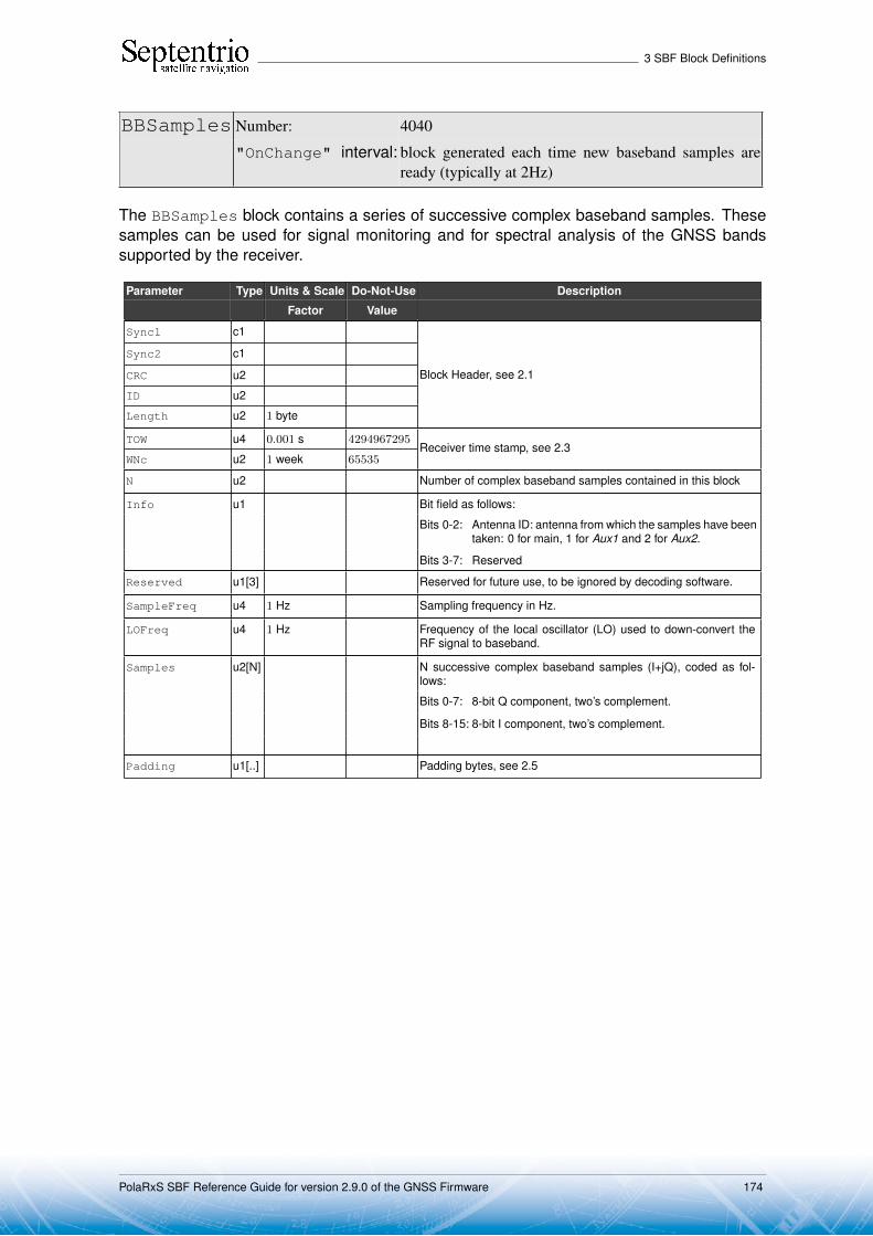
3 SBF Block Definitions
BBSamples Number: 4040
"OnChange" interval: block generated each time new baseband samples areready (typically at 2Hz)
The BBSamples block contains a series of successive complex baseband samples. Thesesamples can be used for signal monitoring and for spectral analysis of the GNSS bandssupported by the receiver.
Parameter Type Units & Scale Do-Not-Use Description
Factor Value
Sync1 c1
Block Header, see 2.1
Sync2 c1
CRC u2
ID u2
Length u2 1 byte
TOW u4 0.001 s 4294967295Receiver time stamp, see 2.3
WNc u2 1 week 65535
N u2 Number of complex baseband samples contained in this block
Info u1 Bit field as follows:
Bits 0-2: Antenna ID: antenna from which the samples have beentaken: 0 for main, 1 for Aux1 and 2 for Aux2.
Bits 3-7: Reserved
Reserved u1[3] Reserved for future use, to be ignored by decoding software.
SampleFreq u4 1 Hz Sampling frequency in Hz.
LOFreq u4 1 Hz Frequency of the local oscillator (LO) used to down-convert theRF signal to baseband.
Samples u2[N] N successive complex baseband samples (I+jQ), coded as fol-lows:
Bits 0-7: 8-bit Q component, two’s complement.
Bits 8-15: 8-bit I component, two’s complement.
Padding u1[..] Padding bytes, see 2.5
PolaRxS SBF Reference Guide for version 2.9.0 of the GNSS Firmware 174

3 SBF Block Definitions
ASCIIIn Number: 4075"OnChange" interval: block generated each time an ASCII string is received
The ASCIIIn block contains a string that has been received on one of the receiver’sconnection ports.
More specifically, this block is output each time an end-of-line character is receivedon a communication port configured to receive ASCIIIn input (with the setDataInOutcommand). The string reported in this block contains all characters received since theprevious occurrence of an end-of-line character.
The maximum length of the string is 2000 characters. If there are more than 2000characters between the occurrence of two successive end-of-line characters, the string isdiscarded
Parameter Type Units & Scale Do-Not-Use Description
Factor Value
Sync1 c1
Block Header, see 2.1
Sync2 c1
CRC u2
ID u2
Length u2 1 byte
TOW u4 0.001 s 4294967295Receiver time stamp, see 2.3
WNc u2 1 week 65535
CD u1 Identifier of the connection to which these statistics apply:
Value of Connection type Example
CD
0-31 COMx, with x=CD 1: COM1
32-63 USBx, with x=CD-32 33: USB1
64-95 IPx, with x=CD-54 64:IP10
96-127 DSKx, with x=CD-96 97:DSK1
128-159 NTRx, with x=CD-128 (NTRIP con-nections)
129:NTR1
160-191 IPSx, with x=CD-160 (IP server con-nections)
161:IPS1
192 BT01 (Bluetooth connection)
196 UHF1 (UHF Modem)
200-205 IPRx, with x=CD-200 (IP receive con-nections)
201:IPR1
206-255 Reserved
Reserved1 u1[3] Reserved, contents to be ignored.
StringLn u2 Length of ASCIIString in characters.
SensorModel c1[20] Not supported, reserved for future use.
SensorType c1[20] Not supported, reserved for future use.
Reserved2 u1[20] Reserved, contents to be ignored.
ASCIIString c1[StringLn] ASCII string. Note that this string is not terminated by the"\0" character. The string does not include the end-of-linecharacter(s) (carrier return and/or line feed).
PolaRxS SBF Reference Guide for version 2.9.0 of the GNSS Firmware 175

3 SBF Block Definitions
Padding u1[..] Padding bytes, see 2.5
PolaRxS SBF Reference Guide for version 2.9.0 of the GNSS Firmware 176

3 SBF Block Definitions
3.17 Deprecated or Obsolete Bocks
BaseLine Number: 5950"OnChange" interval: 10 ms
The BaseLine block contains the relative position of the receiver with respect to the basestation in case of DGPS or RTK positioning.
This block is deprecated and should not be used in new designs. Use the BaseVectorGeodblock instead.
Parameter Type Units & Scale Do-Not-Use Description
Factor Value
Sync1 c1
Block Header, see 2.1
Sync2 c1
CRC u2
ID u2
Length u2 1 byte
TOW u4 0.001 s 4294967295Receiver time stamp, see 2.3
WNc u2 1 week 65535
BaseStationID u2 65535 The base station ID
East f8 1 m −2 · 1010 East baseline component
North f8 1 m −2 · 1010 North baseline component
Up f8 1 m −2 · 1010 Up baseline component
Padding u1[..] Padding bytes, see 2.5
PolaRxS SBF Reference Guide for version 2.9.0 of the GNSS Firmware 177
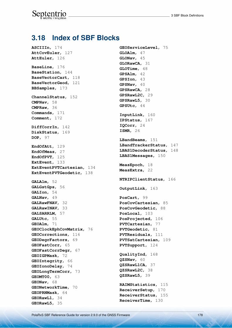
3 SBF Block Definitions
3.18 Index of SBF BlocksASCIIIn, 174AttCovEuler, 127AttEuler, 126
BaseLine, 176BaseStation, 144BaseVectorCart, 118BaseVectorGeod, 121BBSamples, 173
ChannelStatus, 152CMPNav, 58CMPRaw, 36Commands, 171Comment, 172
DiffCorrIn, 142DiskStatus, 169DOP, 97
EndOfAtt, 129EndOfMeas, 27EndOfPVT, 125ExtEvent, 133ExtEventPVTCartesian, 134ExtEventPVTGeodetic, 138
GALAlm, 52GALGstGps, 56GALIon, 54GALNav, 49GALRawFNAV, 32GALRawINAV, 33GALSARRLM, 57GALUtc, 55GEOAlm, 71GEOClockEphCovMatrix, 76GEOCorrections, 116GEODegrFactors, 69GEOFastCorr, 65GEOFastCorrDegr, 67GEOIGPMask, 72GEOIntegrity, 66GEOIonoDelay, 74GEOLongTermCorr, 73GEOMT00, 63GEONav, 68GEONetworkTime, 70GEOPRNMask, 64GEORawL1, 34GEORawL5, 35
GEOServiceLevel, 75GLOAlm, 47GLONav, 45GLORawCA, 31GLOTime, 48GPSAlm, 42GPSIon, 43GPSNav, 40GPSRawCA, 28GPSRawL2C, 29GPSRawL5, 30GPSUtc, 44
InputLink, 160IPStatus, 167IQCorr, 24ISMR, 26
LBandBeams, 151LBandTrackerStatus, 147LBAS1DecoderStatus, 148LBAS1Messages, 150
MeasEpoch, 18MeasExtra, 22
NTRIPClientStatus, 166
OutputLink, 163
PosCart, 99PosCovCartesian, 85PosCovGeodetic, 88PosLocal, 103PosProjected, 106PVTCartesian, 77PVTGeodetic, 81PVTResiduals, 111PVTSatCartesian, 109PVTSupport, 124
QualityInd, 168QZSNav, 60QZSRawL1CA, 37QZSRawL2C, 38QZSRawL5, 39
RAIMStatistics, 115ReceiverSetup, 170ReceiverStatus, 155ReceiverTime, 130
PolaRxS SBF Reference Guide for version 2.9.0 of the GNSS Firmware 178

3 SBF Block Definitions
RTCMDatum, 145
SatVisibility, 159
VelCovCartesian, 91VelCovGeodetic, 94
xPPSOffset, 131
PolaRxS SBF Reference Guide for version 2.9.0 of the GNSS Firmware 179