Polaroid FLM LCD TV Service Manual 20060407diagramas.diagramasde.com/otros/POLAROID FLM-2632M... ·...
49
LCD Television with NTSC/ATSC Tuner FLM-2632, FLM-2632M, FLM-2634B, FLM-3232, FLM-3232M, FLM-323B, FLM-3234B, FLM-3732, FLM-373B, FLM-3734B, FLM-3732M SERVICE MANUAL 20060418
Transcript of Polaroid FLM LCD TV Service Manual 20060407diagramas.diagramasde.com/otros/POLAROID FLM-2632M... ·...
LCD Television with NTSC/ATSC Tuner FLM-2632, FLM-2632M, FLM-2634B, FLM-3232, FLM-3232M, FLM-323B, FLM-3234B, FLM-3732, FLM-373B, FLM-3734B, FLM-3732M
SERVICE MANUAL 20060418
2
20060321
3
Precautions and Safety Notices
4
Prior to using this service manual, please ensure that you have carefully followed all the procedures outlined in the user's manual for this product. (1) Read all of these instructions. (2) Save these instructions. (3) Follow all warnings and instructions marked on the product. (4) Unplug this product from the wall outlet before cleaning. Do not use liquid cleaners or aerosol cleaners, use a
damp cloth for cleaning. (5) Do not use this product near water. (6) Do not place this product on an unstable cart, stand or table. The product may fall, causing serious damage to the product. (7) Slots and openings in the cabinet and the back or bottom are provided for ventilation, to ensure reliable
operation of the product and to protect it from overheating, those openings must not be blocked or covered. The openings should never be blocked by placing the product on a bed, sofa, rug, or other similar surface. This product should not be placed in a built-in installation unless proper ventilation is provided.
(8) This product should be operated from the type of power source indicated on the marketing label. If you are not sure of the type of power available, consult your dealer or local power company
(9) This product is equipped with a 3-wire grounding type plug, a plug having a third (grounding) pin. This plug will only fit into a grounding-type power outlet. This is a safety feature, if you are unable to insert the plug into the outlet, contact your electrician to replace your obsolete outlet. Do not ignore the purpose of the grounding-type plug.
(10) Do not allow anything to rest on the power cord. Do not locate this product where people will walk on the cord. (11) If an extension cord is used with this product, make sure that the total of the ampere ratings on the product
plugged into the extension cord to the waplugged into outlet does not exceed 15 ampere. (12) Never push objects of any kind into this product through cabinet slots as they may touch dangerous voltage
points or short out parts that could result in a risk of fire or electric shock. Never spill liquid of any kind on the product.
(13) Do not attempt to service this product yourself, as opening or removing covers may expose you to dangerous voltage points or other risks. Refer all servicing to service personnel.
(14) Unplug this product from the wall outlet and refer servicing to qualified service personnel under the following conditions: a. When the power cord or plug is damaged or frayed. b. If liquid has been spilled into the product. c. If the product has been exposed to rain or water. d. If the product does not operate normally, when the operating instructions are followed. Adjust only those
controls that are covered by the operating instructions since improper adjustment of other controls may result in damage and will often require extension work by a qualified technician to restore the product to normal operation.
e. If the product has been dropped or the cabinet has been damaged. f. If the product exhibits a distinct change in performance, indicating a need for service.
5
TABLE OF CONTENTS
1 . S p e c i f i c a t i o n s · · · · · · · · · · · · · · · · · · · · · · · · · · · · · · · · · · · · · · · · · · · · · · · · · 6
2. Front Panel Function Control Description ························· 13
3. Troubleshooting Flow Chart · · · · · · · · · · · · · · · · · · · · · · · · · · · · · · · · · · 19
4. Display Cell Defects ············································ 22
5. Disassembly Procedure· · · · · · · · · · · · · · · · · · · · · · · · · · · · · · · · · · · · · · · · ·23
6. A/V Board and Front/Side Control Button Disassembly····················33
7. Recommended Spare Parts List········································35
8. Exploded Diagram and Spare Parts List ·························· 37
9. B l o c k D i a g r a m s · · · · · · · · · · · · · · · · · · · · · · · · · · · · · · · · · · · · · · · · · · · · · 4 0
10. Schematic Diagrams · · · · · · · · · · · · · · · · · · · · · · · · · · · · · · · · · · · · · · · · · 41
11. PCB Layout Diagrams ··· · · · · · · · · · · · · · · · · · · · · · · · · ············· 46
6
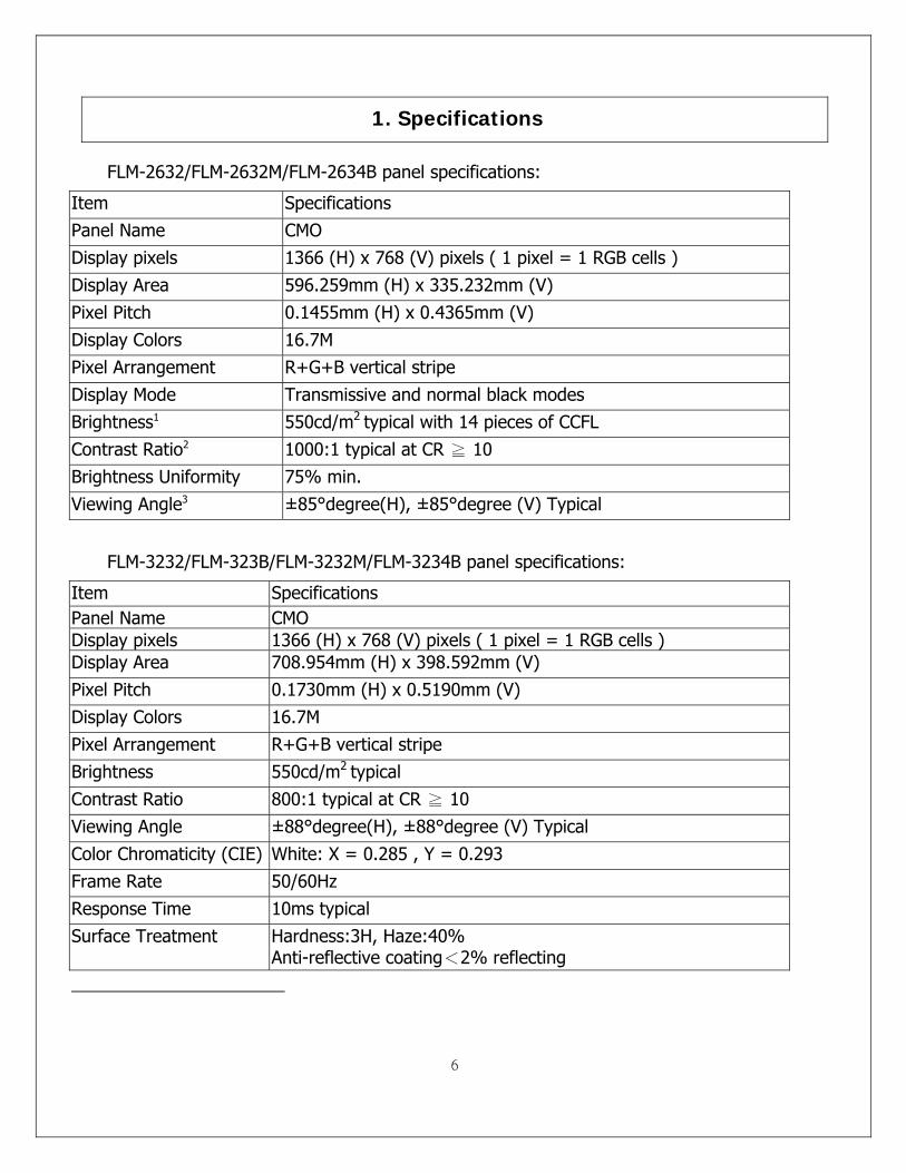
1. Specifications
FLM-2632/FLM-2632M/FLM-2634B panel specifications:
Item Specifications Panel Name CMO Display pixels 1366 (H) x 768 (V) pixels ( 1 pixel = 1 RGB cells ) Display Area 596.259mm (H) x 335.232mm (V) Pixel Pitch 0.1455mm (H) x 0.4365mm (V) Display Colors 16.7M Pixel Arrangement R+G+B vertical stripe Display Mode Transmissive and normal black modes Brightness1 550cd/m2 typical with 14 pieces of CCFL Contrast Ratio2 1000:1 typical at CR ≧ 10 Brightness Uniformity 75% min. Viewing Angle3 ±85°degree(H), ±85°degree (V) Typical
FLM-3232/FLM-323B/FLM-3232M/FLM-3234B panel specifications:
Item Specifications Panel Name CMO Display pixels 1366 (H) x 768 (V) pixels ( 1 pixel = 1 RGB cells ) Display Area 708.954mm (H) x 398.592mm (V) Pixel Pitch 0.1730mm (H) x 0.5190mm (V) Display Colors 16.7M Pixel Arrangement R+G+B vertical stripe Brightness 550cd/m2 typical Contrast Ratio 800:1 typical at CR ≧ 10 Viewing Angle ±88°degree(H), ±88°degree (V) Typical Color Chromaticity (CIE) White: X = 0.285 , Y = 0.293 Frame Rate 50/60Hz Response Time 10ms typical Surface Treatment Hardness:3H, Haze:40%
Anti-reflective coating<2% reflecting
7
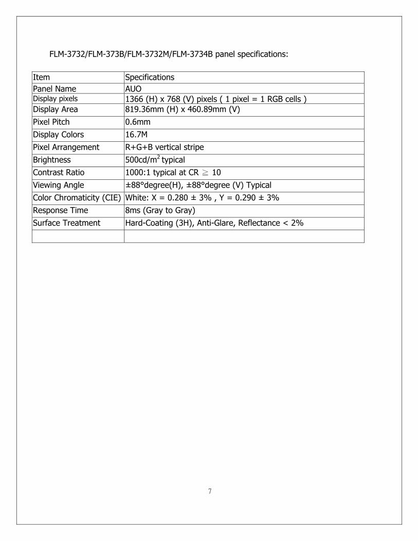
FLM-3732/FLM-373B/FLM-3732M/FLM-3734B panel specifications:
Item Specifications Panel Name AUO Display pixels 1366 (H) x 768 (V) pixels ( 1 pixel = 1 RGB cells ) Display Area 819.36mm (H) x 460.89mm (V) Pixel Pitch 0.6mm Display Colors 16.7M Pixel Arrangement R+G+B vertical stripe Brightness 500cd/m2 typical Contrast Ratio 1000:1 typical at CR ≧ 10 Viewing Angle ±88°degree(H), ±88°degree (V) Typical Color Chromaticity (CIE) White: X = 0.280 ± 3% , Y = 0.290 ± 3% Response Time 8ms (Gray to Gray) Surface Treatment Hard-Coating (3H), Anti-Glare, Reflectance < 2%
8
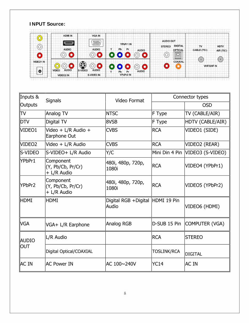
INPUT Source:
Connector types Inputs &
Outputs Signals Video Format
OSD
TV Analog TV NTSC F Type TV (CABLE/AIR)
DTV Digital TV 8VSB F Type HDTV (CABLE/AIR)
VIDEO1 Video + L/R Audio + Earphone Out
CVBS RCA VIDEO1 (SIDE)
VIDEO2 Video + L/R Audio CVBS RCA VIDEO2 (REAR)
S-VIDEO S-VIDEO+ L/R Audio Y/C Mini Din 4 Pin VIDEO3 (S-VIDEO)
YPbPr1 Component (Y, Pb/Cb, Pr/Cr) + L/R Audio
480i, 480p, 720p, 1080i RCA VIDEO4 (YPbPr1)
YPbPr2 Component (Y, Pb/Cb, Pr/Cr) + L/R Audio
480i, 480p, 720p, 1080i RCA VIDEO5 (YPbPr2)
HDMI HDMI Digital RGB +Digital Audio
HDMI 19 Pin VIDEO6 (HDMI)
VGA VGA+ L/R Earphone Analog RGB D-SUB 15 Pin COMPUTER (VGA)
L/R Audio RCA STEREO AUDIO OUT
Digital Optical/COAXIAL TOSLINK/RCA DIGITAL
AC IN AC Power IN AC 100~240V YC14 AC IN
9
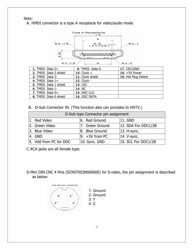
Note: A. HMDI connector is a type A receptacle for video/audio mode.
1. TMDS Data 2+ 9. TMDS Data 0- 17. CEC/GND 2. TMDS Data 2 shield 10. Clock + 18. +5V Power 3. TMDS Data 2- 11. Clock shield 19. Hot Plug Detect 4. TMDS Data 1+ 12. Clock - 5. TMDS Data 1 shield 13. CEC 6. TMDS Data 1- 14. NC 7. TMDS Data 0+ 15. DDC CLK 8. TMDS Data 0 shield 16. DDC DATA
B. D-Sub Connector IN. (This function also can provides to HDTV.)
D-Sub type Connector pin assignment
1. Red Video 6. Red Ground 11. GND 2. Green Video 7. Green Ground 12. SDA For DDC1/2B 3. Blue Video 8. Blue Ground 13. H-sync. 4. GND 9. +5V from PC 14. V-sync. 5. Vdd from PC for DDC 10. Sync. GND 15. SCL For DDC1/2B
C. RCA jacks are all female type.
D. Mini DIN CNC 4 Pins (SCN570S3NS00000) for S-video, the pin assignment is described as below:
1: Ground 2: Ground 3: Y 4: C
10
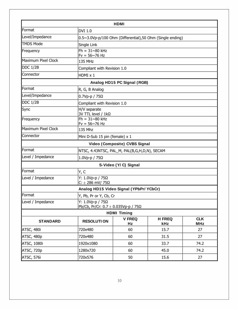
HDMI Format DVI 1.0 Level/Impedance 0.5~3.0Vp-p/100 Ohm (Differential),50 Ohm (Single ending) TMDS Mode Single Link Frequency Fh = 31~80 kHz
Fv = 56~76 Hz Maximum Pixel Clock 135 MHz DDC 1/2B Compliant with Revision 1.0 Connector HDMI x 1
Analog HD15 PC Signal (RGB) Format R, G, B Analog Level/Impedance 0.7Vp-p / 75Ω DDC 1/2B Compliant with Revision 1.0 Sync H/V separate
3V TTL level / 1kΩ Frequency Fh = 31~80 kHz
Fv = 56~76 Hz Maximum Pixel Clock 135 Mhz Connector Mini D-Sub 15 pin (female) x 1
Video (Composite) CVBS Signal Format NTSC, 4.43NTSC, PAL_M, PAL(B,G,H,D,N), SECAM Level / Impedance 1.0Vp-p / 75Ω
S-Video (Y/C) Signal Format Y, C Level / Impedance Y: 1.0Vp-p / 75Ω
C: ± 286 mV/ 75Ω
Analog HD15 Video Signal (YPbPr/YCbCr) Format Y, Pb, Pr or Y, Cb, Cr Level / Impedance Y: 1.0Vp-p / 75Ω
Pb/Cb, Pr/Cr: 0.7 ± 0.035Vp-p / 75Ω
HDMI Timing
STANDARD RESOLUTION V FREQ Hz
H FREQ kHz
CLK MHz
ATSC, 480i 720x480 60 15.7 27
ATSC, 480p 720x480 60 31.5 27
ATSC, 1080i 1920x1080 60 33.7 74.2
ATSC, 720p 1280x720 60 45.0 74.2
ATSC, 576i 720x576 50 15.6 27
11
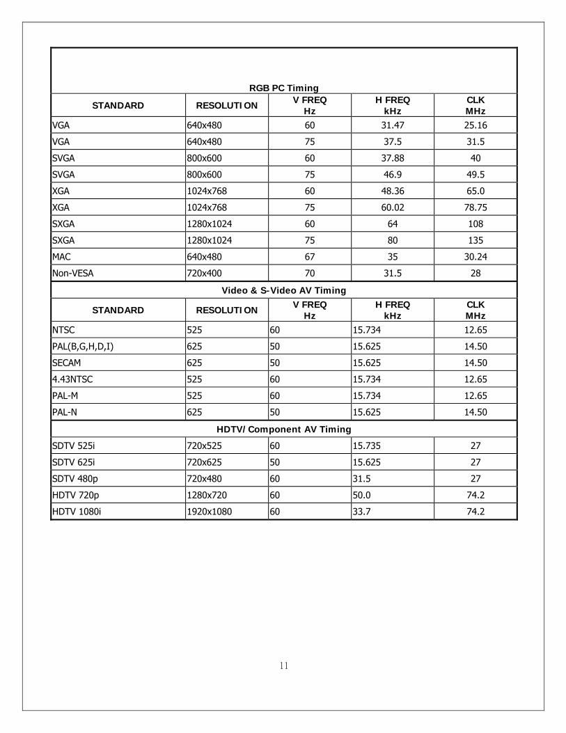
RGB PC Timing
STANDARD RESOLUTION V FREQ Hz
H FREQ kHz
CLK MHz
VGA 640x480 60 31.47 25.16
VGA 640x480 75 37.5 31.5
SVGA 800x600 60 37.88 40
SVGA 800x600 75 46.9 49.5
XGA 1024x768 60 48.36 65.0
XGA 1024x768 75 60.02 78.75
SXGA 1280x1024 60 64 108
SXGA 1280x1024 75 80 135
MAC 640x480 67 35 30.24
Non-VESA 720x400 70 31.5 28
Video & S-Video AV Timing
STANDARD RESOLUTION V FREQ Hz
H FREQ kHz
CLK MHz
NTSC 525 60 15.734 12.65
PAL(B,G,H,D,I) 625 50 15.625 14.50
SECAM 625 50 15.625 14.50
4.43NTSC 525 60 15.734 12.65
PAL-M 525 60 15.734 12.65
PAL-N 625 50 15.625 14.50
HDTV/Component AV Timing
SDTV 525i 720x525 60 15.735 27
SDTV 625i 720x625 50 15.625 27
SDTV 480p 720x480 60 31.5 27
HDTV 720p 1280x720 60 50.0 74.2
HDTV 1080i 1920x1080 60 33.7 74.2
12
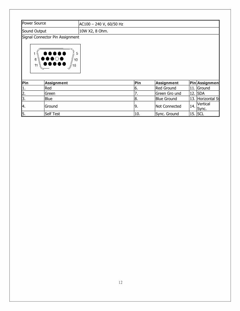
Power Source AC100 – 240 V, 60/50 Hz
Sound Output 10W X2, 8 Ohm. Signal Connector Pin Assignment
Pin Assignment Pin Assignment Pin Assignment1. Red 6. Red Ground 11. Ground 2. Green 7. Green Gro und 12. SDA 3. Blue 8. Blue Ground 13. Horizontal Sy
4. Ground 9. Not Connected 14. Vertical Sync.
5. Self Test 10. Sync. Ground 15. SCL
13
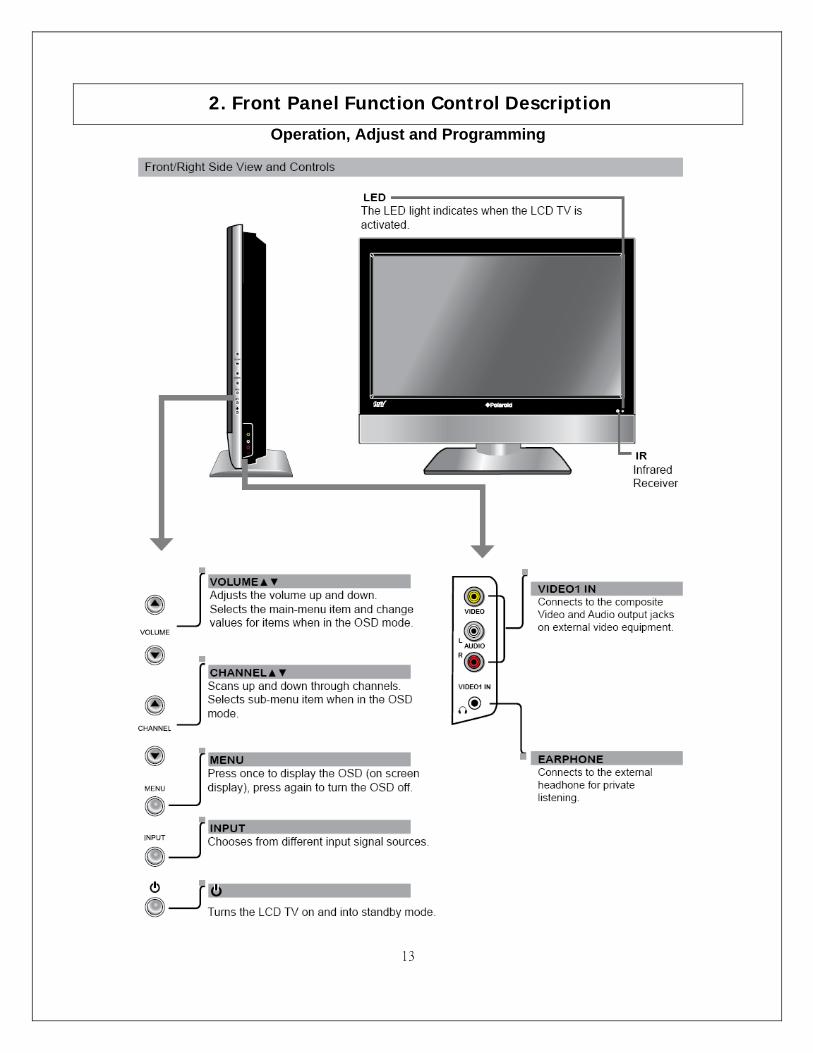
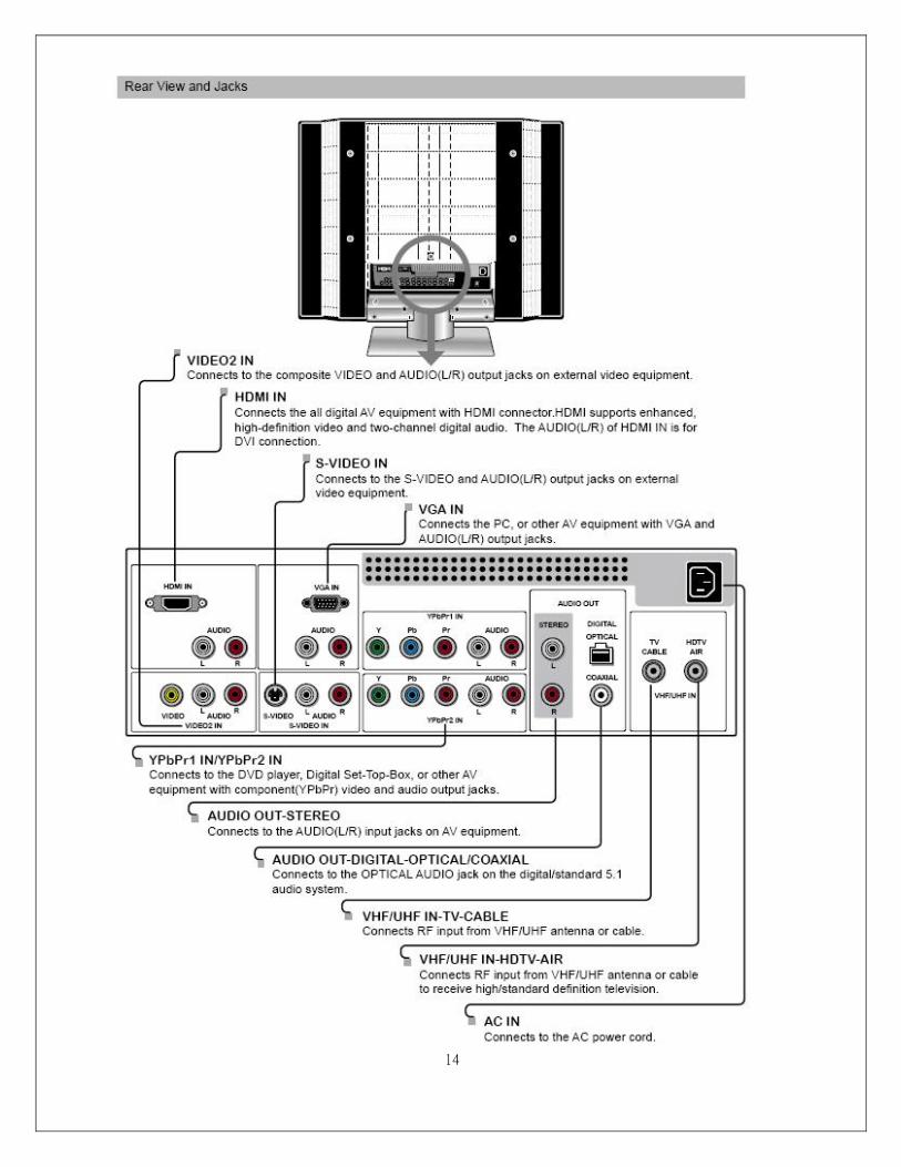
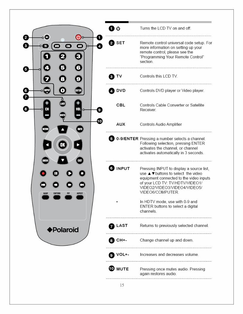
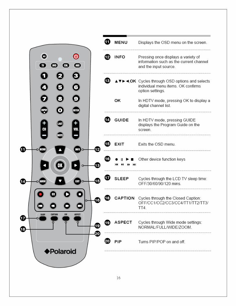
2. Front Panel Function Control Description
Operation, Adjust and Programming
14
15
16
17
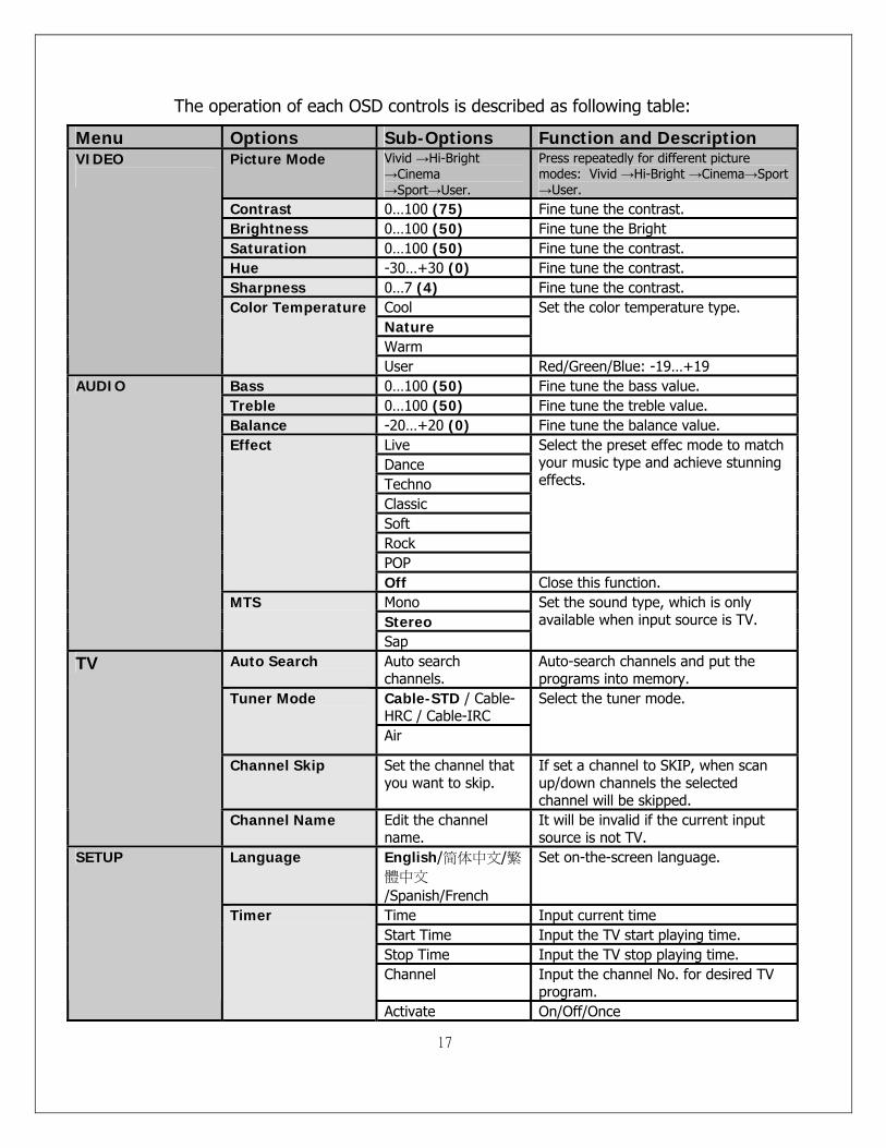
The operation of each OSD controls is described as following table:
Menu Options Sub-Options Function and Description Picture Mode Vivid →Hi-Bright
→Cinema →Sport→User.
Press repeatedly for different picture modes: Vivid →Hi-Bright →Cinema→Sport →User.
Contrast 0…100 (75) Fine tune the contrast. Brightness 0…100 (50) Fine tune the Bright Saturation 0…100 (50) Fine tune the contrast. Hue -30…+30 (0) Fine tune the contrast. Sharpness 0…7 (4) Fine tune the contrast.
Cool Nature Warm
Set the color temperature type.
VIDEO
Color Temperature
User Red/Green/Blue: -19…+19 Bass 0…100 (50) Fine tune the bass value. Treble 0…100 (50) Fine tune the treble value. Balance -20…+20 (0) Fine tune the balance value.
Live Dance Techno Classic Soft Rock POP
Select the preset effec mode to match your music type and achieve stunning effects.
Effect
Off Close this function. Mono Stereo
AUDIO
MTS
Sap
Set the sound type, which is only available when input source is TV.
Auto Search Auto search channels.
Auto-search channels and put the programs into memory.
Cable-STD / Cable-HRC / Cable-IRC
Tuner Mode
Air
Select the tuner mode.
Channel Skip Set the channel that you want to skip.
If set a channel to SKIP, when scan up/down channels the selected channel will be skipped.
TV
Channel Name Edit the channel name.
It will be invalid if the current input source is not TV.
Language English/简体中文/繁體中文
/Spanish/French
Set on-the-screen language.
Time Input current time Start Time Input the TV start playing time. Stop Time Input the TV stop playing time. Channel Input the channel No. for desired TV
program.
SETUP
Timer
Activate On/Off/Once
18
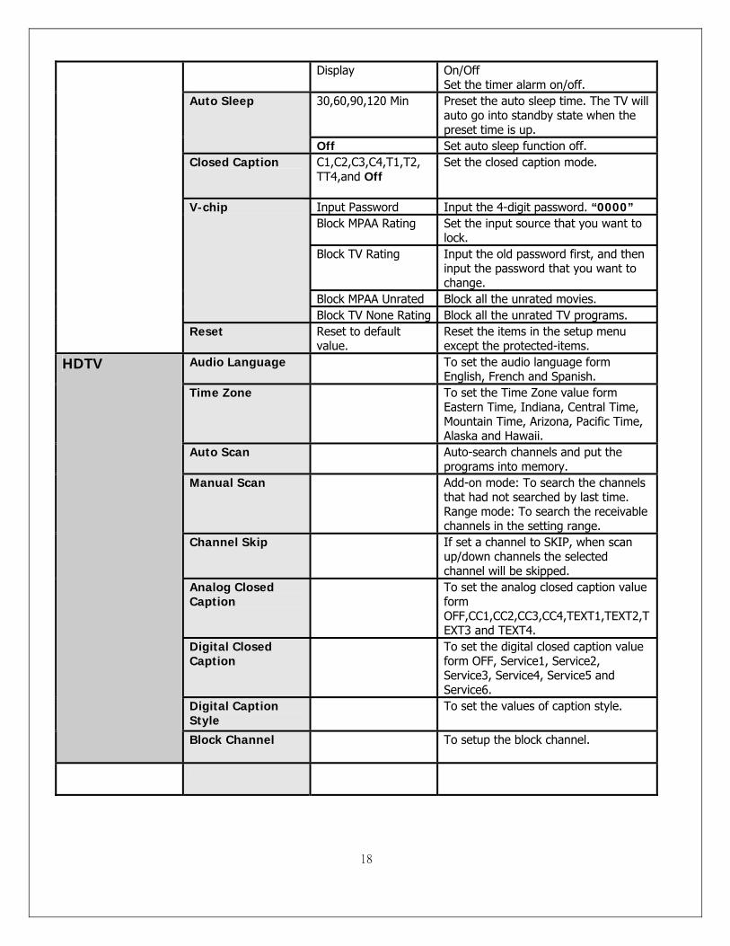
Display On/Off Set the timer alarm on/off.
30,60,90,120 Min Preset the auto sleep time. The TV will auto go into standby state when the preset time is up.
Auto Sleep
Off Set auto sleep function off. Closed Caption C1,C2,C3,C4,T1,T2,
TT4,and Off
Set the closed caption mode.
Input Password Input the 4-digit password. “0000” Block MPAA Rating Set the input source that you want to
lock. Block TV Rating Input the old password first, and then
input the password that you want to change.
Block MPAA Unrated Block all the unrated movies.
V-chip
Block TV None Rating Block all the unrated TV programs.
Reset Reset to default value.
Reset the items in the setup menu except the protected-items.
Audio Language To set the audio language form English, French and Spanish.
Time Zone To set the Time Zone value form Eastern Time, Indiana, Central Time, Mountain Time, Arizona, Pacific Time, Alaska and Hawaii.
Auto Scan Auto-search channels and put the programs into memory.
Manual Scan Add-on mode: To search the channels that had not searched by last time. Range mode: To search the receivable channels in the setting range.
Channel Skip If set a channel to SKIP, when scan up/down channels the selected channel will be skipped.
Analog Closed Caption
To set the analog closed caption value form OFF,CC1,CC2,CC3,CC4,TEXT1,TEXT2,TEXT3 and TEXT4.
Digital Closed Caption
To set the digital closed caption value form OFF, Service1, Service2, Service3, Service4, Service5 and Service6.
Digital Caption Style
To set the values of caption style.
HDTV
Block Channel To setup the block channel.
19
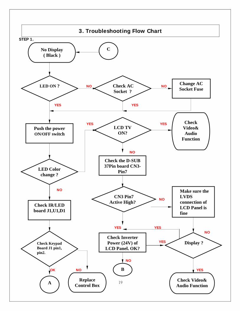
3. Troubleshooting Flow Chart STEP 1. NO NO
YES YES
YES YES
NO NO NO YES YES NO YES NO OK NO YES
No Display ( Black )
LED ON ?
Push the power ON/OFF switch
LED Color change ?
Check IR/LED board J1,U1,D1
Check Keypad Board J1 pin1, pin2.
LCD TV ON?
Check Video& Audio
Function
Make sure the LVDS connection of LCD Panel is fine
CN3 Pin7 Active High?
Check the D-SUB 37Pin board CN3-
Pin7
Check Inverter Power (24V) of
LCD Panel, OK?
B
Display ?
Check AC Socket ?
Change AC Socket Fuse
C
A Replace Control Box
Check Video& Audio Function
20
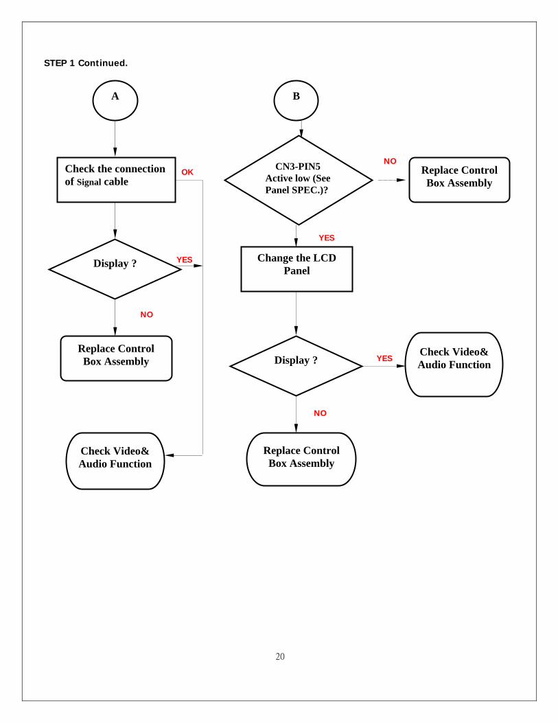
STEP 1 Continued. NO NO OK YES YES NO YES NO
B
CN3-PIN5 Active low (See Panel SPEC.)?
Change the LCD Panel
Display ? Check Video& Audio Function
Replace Control Box Assembly
A
Check the connection of Signal cable
Display ?
Check Video& Audio Function
Replace Control Box Assembly
Replace Control Box Assembly
21
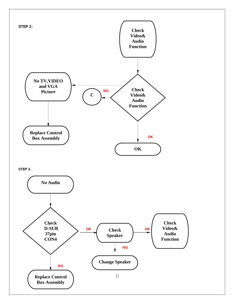
STEP 2. NG OK STEP 3. OK OK NG NG
No TV,VIDEO and VGA Picture
Replace Control Box Assembly
No Audio
Change Speaker
Check D-SUB 37pin CON4
Check Speaker
Check Video& Audio
Function
Replace Control Box Assembly
Check Video& Audio
Function
Check Video& Audio
Function
OK
C
22
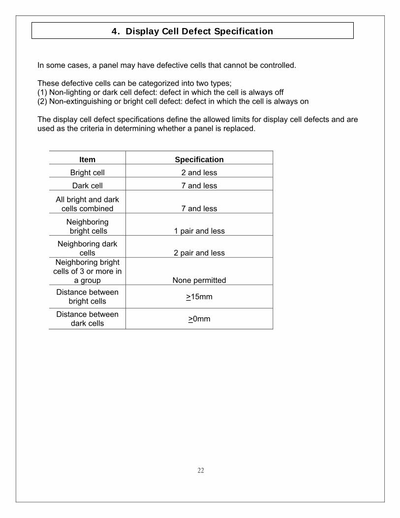
In some cases, a panel may have defective cells that cannot be controlled. These defective cells can be categorized into two types; (1) Non-lighting or dark cell defect: defect in which the cell is always off (2) Non-extinguishing or bright cell defect: defect in which the cell is always on The display cell defect specifications define the allowed limits for display cell defects and are used as the criteria in determining whether a panel is replaced.
Item Specification Bright cell 2 and less
Dark cell 7 and less
All bright and dark cells combined 7 and less
Neighboring bright cells 1 pair and less
Neighboring dark cells 2 pair and less
Neighboring bright cells of 3 or more in
a group None permitted Distance between
bright cells >15mm
Distance between dark cells >0mm
4. Display Cell Defect Specification
23
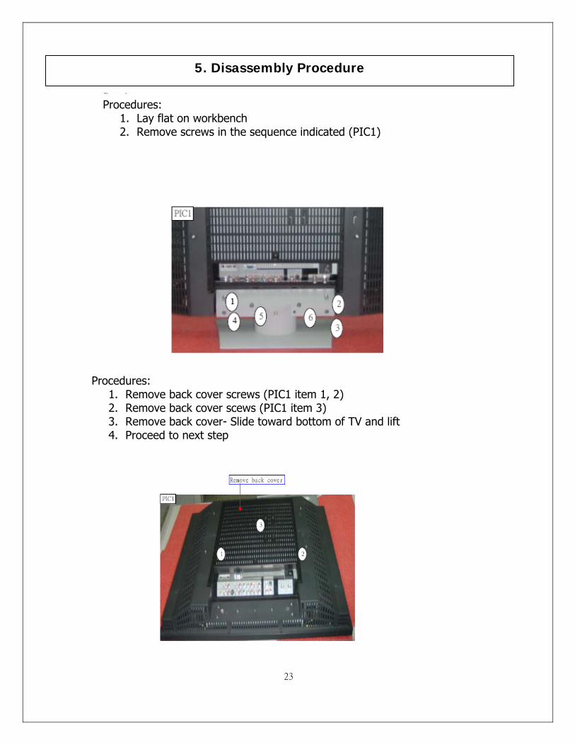
5. Disassembly Procedure
Procedures: 1. Lay flat on workbench 2. Remove screws in the sequence indicated (PIC1)
Procedures: 1. Remove back cover screws (PIC1 item 1, 2) 2. Remove back cover scews (PIC1 item 3) 3. Remove back cover- Slide toward bottom of TV and lift 4. Proceed to next step
24
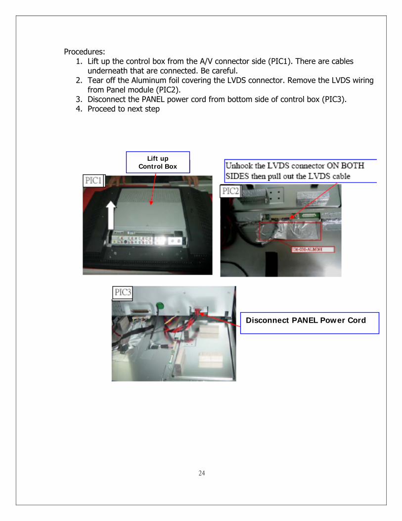
Procedures: 1. Lift up the control box from the A/V connector side (PIC1). There are cables
underneath that are connected. Be careful. 2. Tear off the Aluminum foil covering the LVDS connector. Remove the LVDS wiring
from Panel module (PIC2). 3. Disconnect the PANEL power cord from bottom side of control box (PIC3). 4. Proceed to next step
Lift up Control Box
Disconnect PANEL Power Cord
25
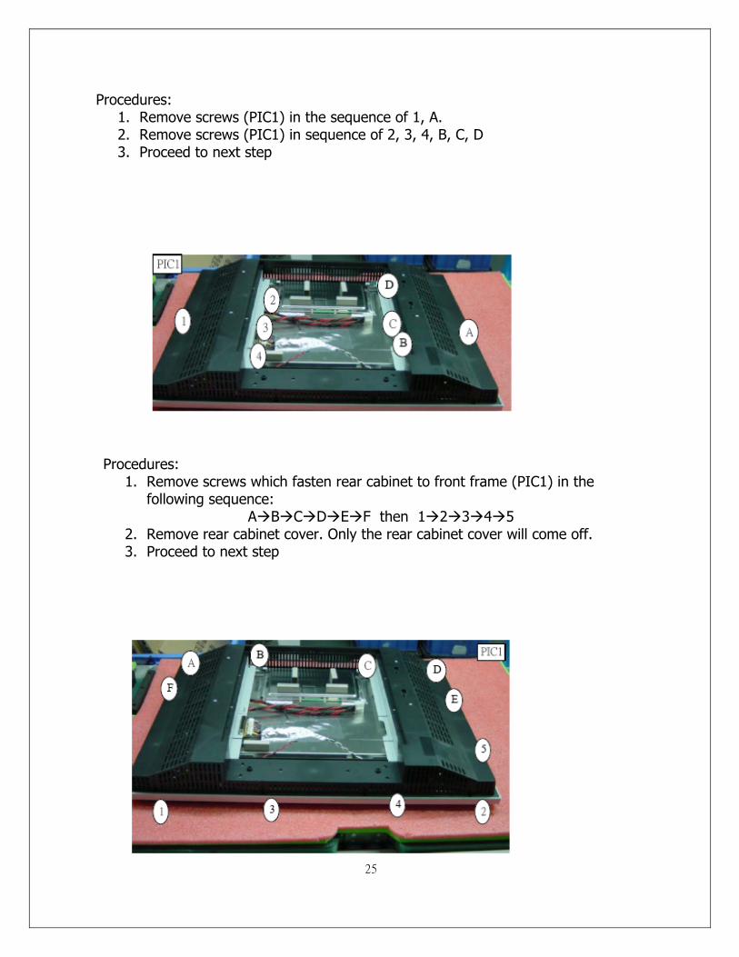
Procedures: 1. Remove screws (PIC1) in the sequence of 1, A. 2. Remove screws (PIC1) in sequence of 2, 3, 4, B, C, D 3. Proceed to next step
Procedures: 1. Remove screws which fasten rear cabinet to front frame (PIC1) in the
following sequence: A B C D E F then 1 2 3 4 5
2. Remove rear cabinet cover. Only the rear cabinet cover will come off. 3. Proceed to next step
26
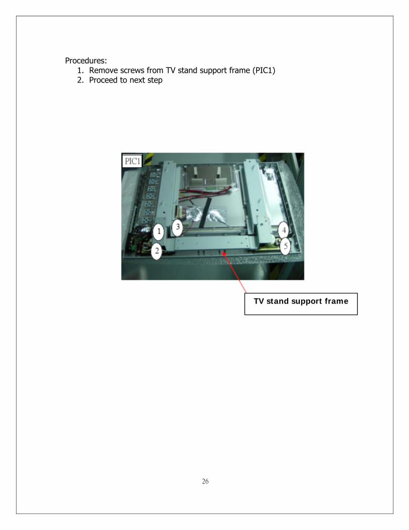
Procedures: 1. Remove screws from TV stand support frame (PIC1) 2. Proceed to next step
TV stand support frame
27
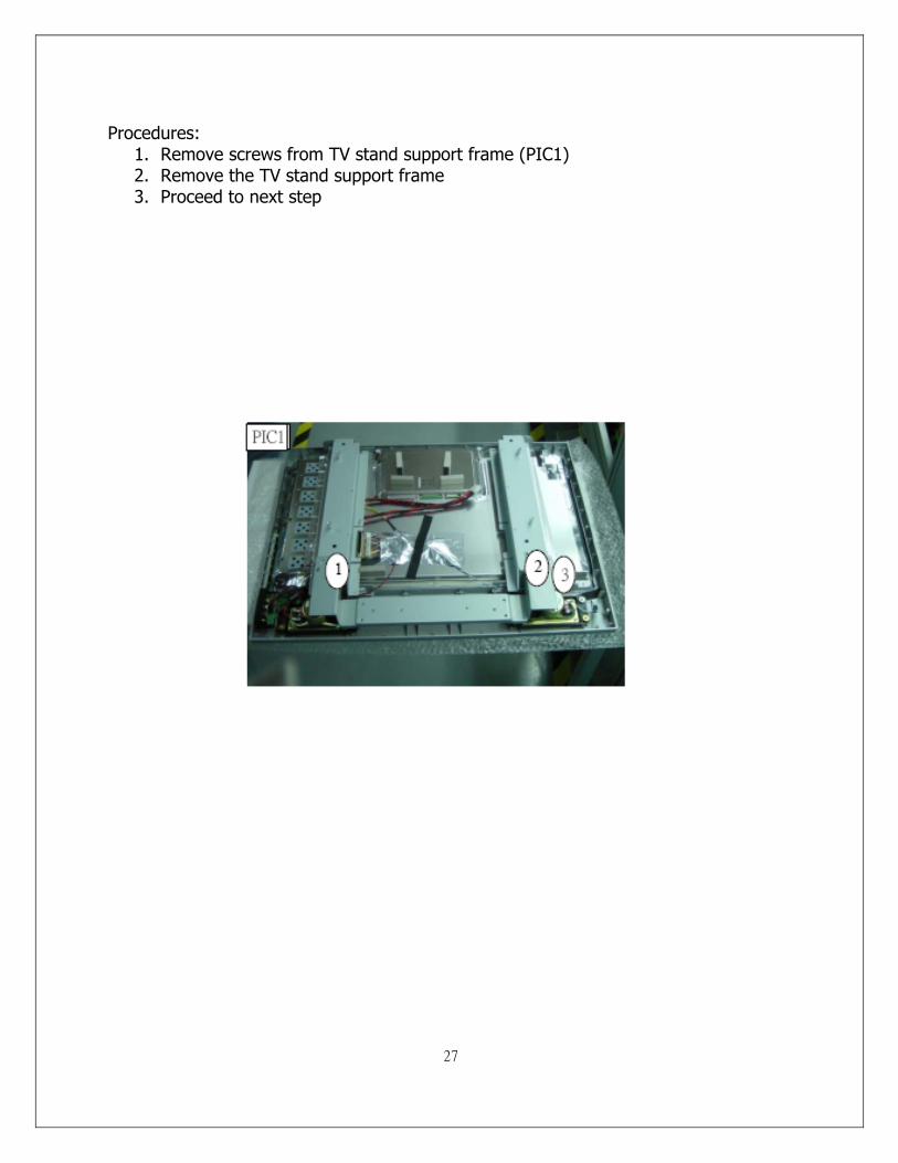
Procedures: 1. Remove screws from TV stand support frame (PIC1) 2. Remove the TV stand support frame 3. Proceed to next step
28
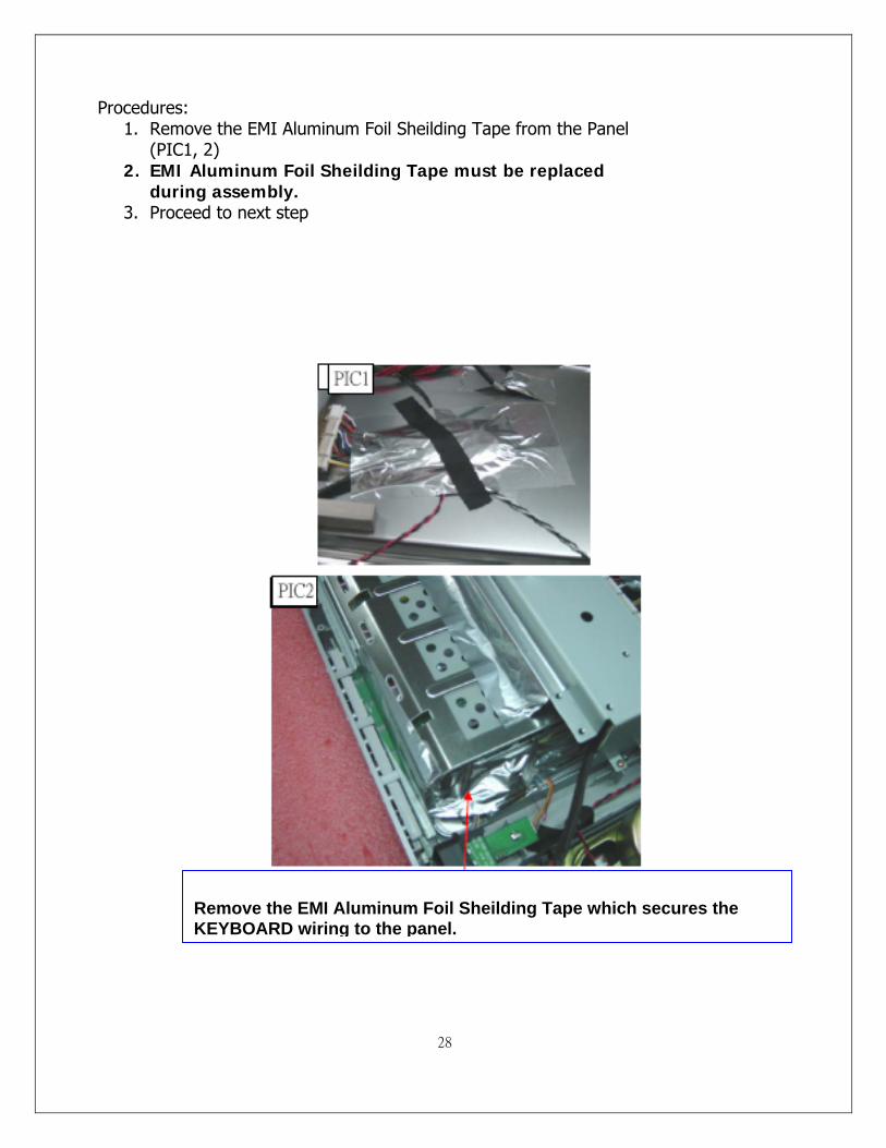
Remove the EMI Aluminum Foil Sheilding Tape which secures the KEYBOARD wiring to the panel.
Procedures: 1. Remove the EMI Aluminum Foil Sheilding Tape from the Panel
(PIC1, 2) 2. EMI Aluminum Foil Sheilding Tape must be replaced
during assembly. 3. Proceed to next step
29
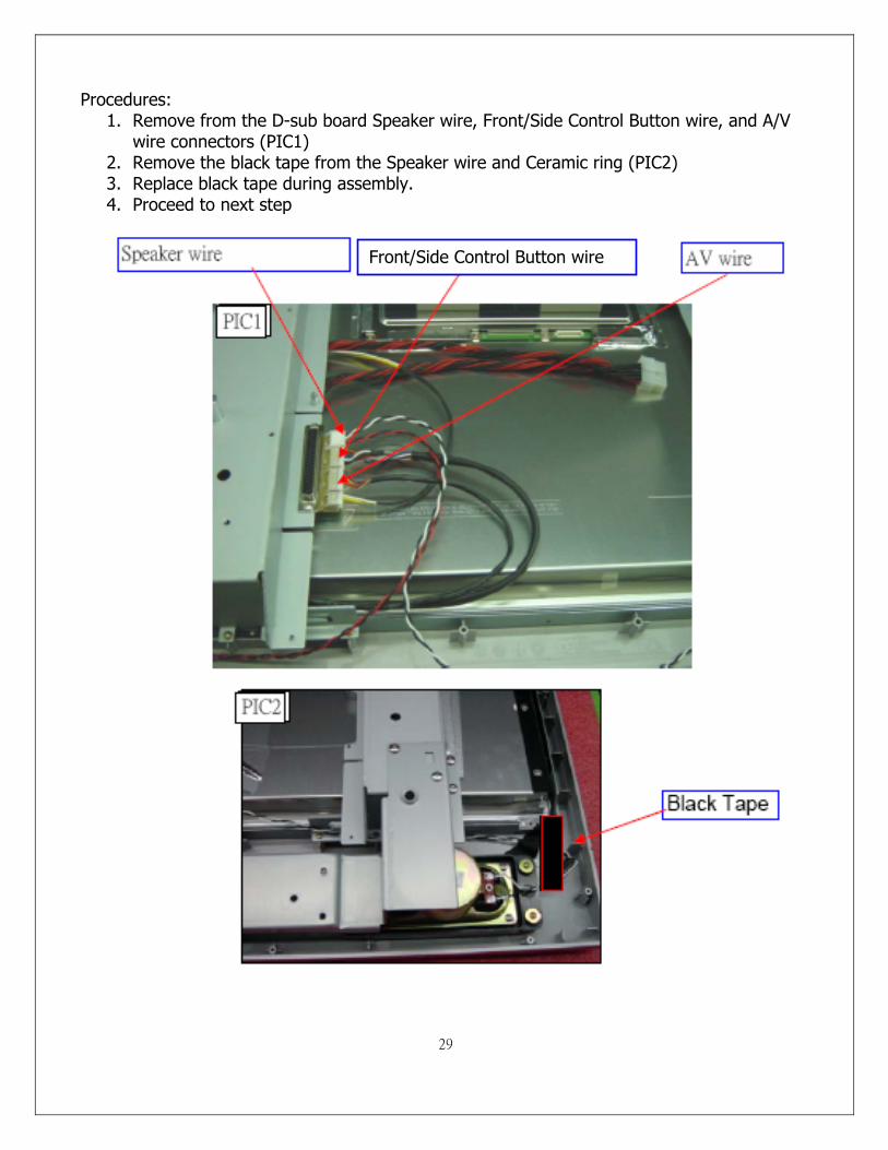
Procedures:
1. Remove from the D-sub board Speaker wire, Front/Side Control Button wire, and A/V wire connectors (PIC1)
2. Remove the black tape from the Speaker wire and Ceramic ring (PIC2) 3. Replace black tape during assembly. 4. Proceed to next step
Front/Side Control Button wire
30
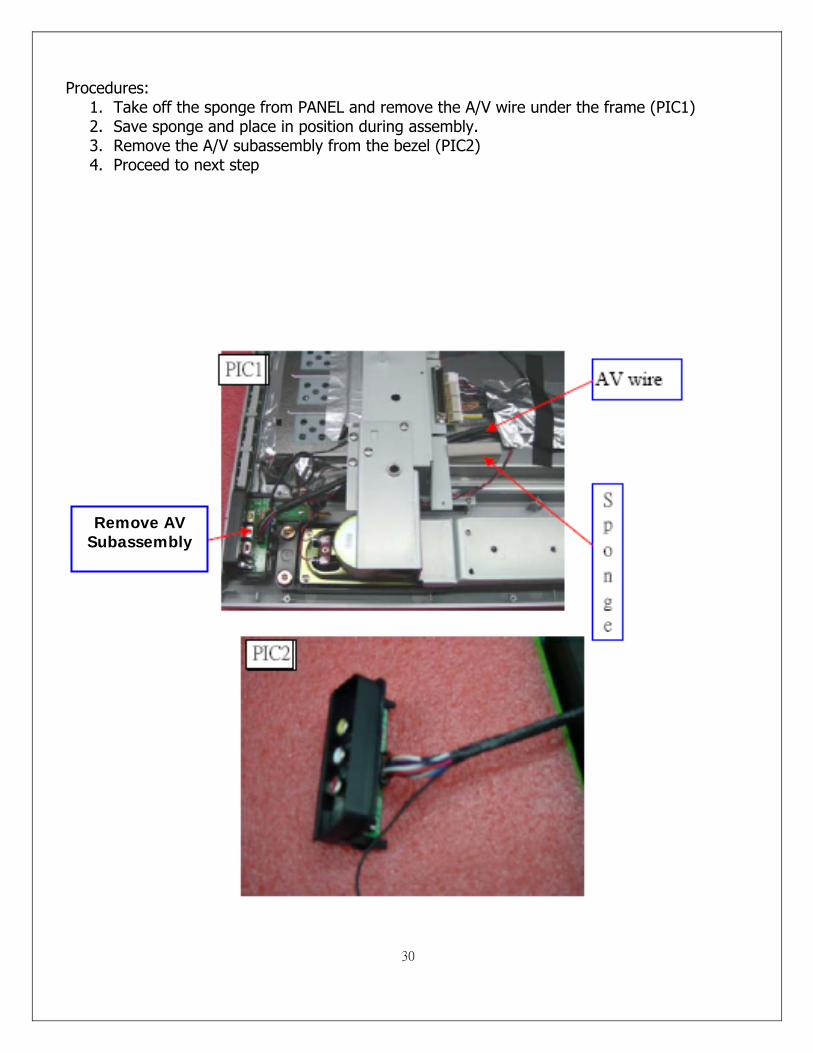
Procedures: 1. Take off the sponge from PANEL and remove the A/V wire under the frame (PIC1) 2. Save sponge and place in position during assembly. 3. Remove the A/V subassembly from the bezel (PIC2) 4. Proceed to next step
Remove AV Subassembly
31
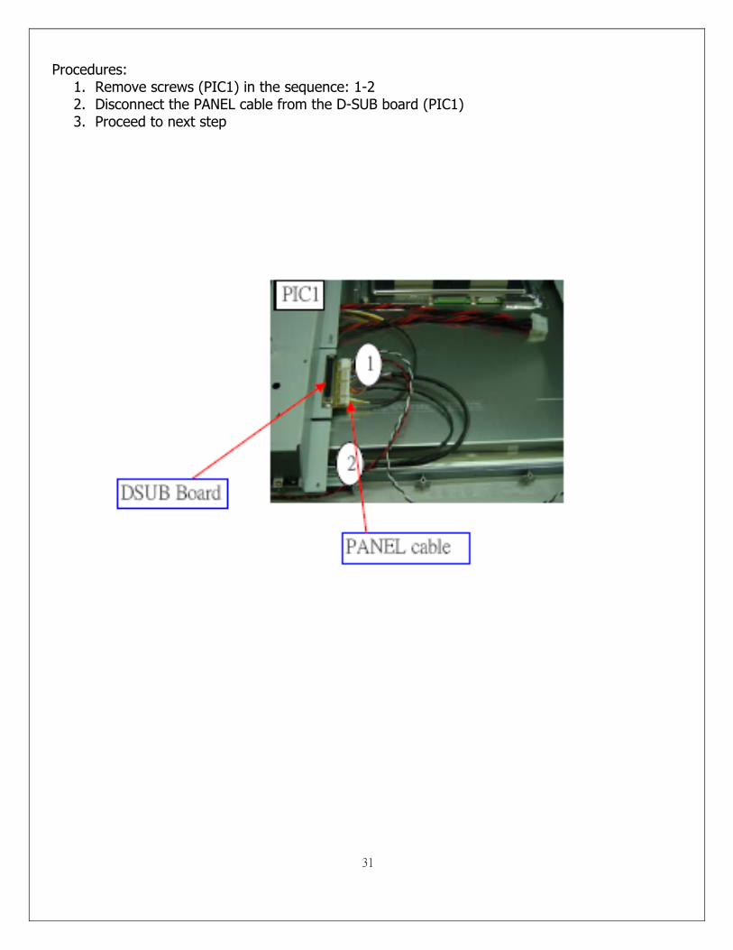
Procedures: 1. Remove screws (PIC1) in the sequence: 1-2 2. Disconnect the PANEL cable from the D-SUB board (PIC1) 3. Proceed to next step
32
7. Exploded Diagram and Spare Parts List
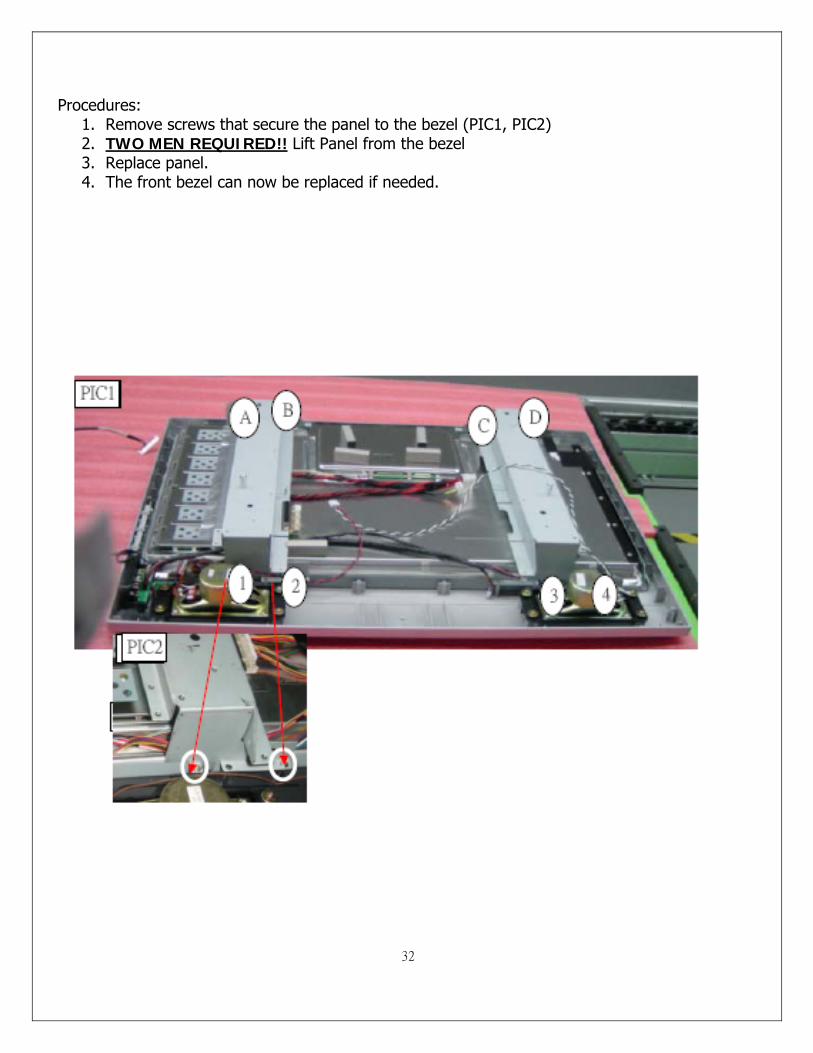
Procedures: 1. Remove screws that secure the panel to the bezel (PIC1, PIC2) 2. TWO MEN REQUIRED!! Lift Panel from the bezel 3. Replace panel. 4. The front bezel can now be replaced if needed.

33
A/V Board Removal and Replacement 1. Disassemble rear cabinet and remove A/V assembly. 2. Using a small pair of wire cutters grip the side locking tab and pivot back towards the A/V
cable connector (PIC1). Locking tab should only pivot about 45 degrees. Do the same for the opposite side of the A/V assembly.
3. Slide out A/V board and replace (PIC2). 4. Push locking tabs in to secure replaced A/V board.
PIC1 PIC2
6. A/V Board and Front/Side Control Button Disassembly
34
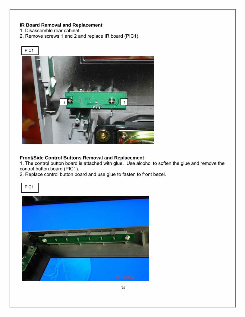
IR Board Removal and Replacement 1. Disassemble rear cabinet. 2. Remove screws 1 and 2 and replace IR board (PIC1). Front/Side Control Buttons Removal and Replacement 1. The control button board is attached with glue. Use alcohol to soften the glue and remove the control button board (PIC1). 2. Replace control button board and use glue to fasten to front bezel.
PIC1
1 2
PIC1
35
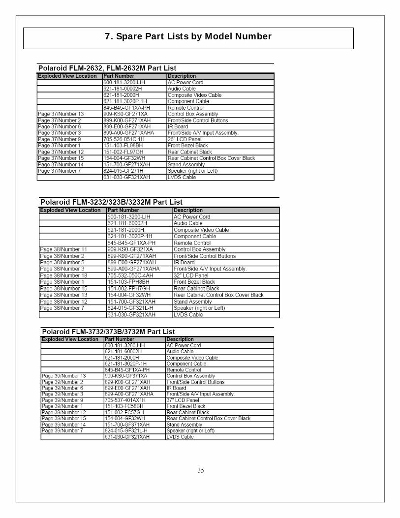
7. Spare Part Lists by Model Number
36
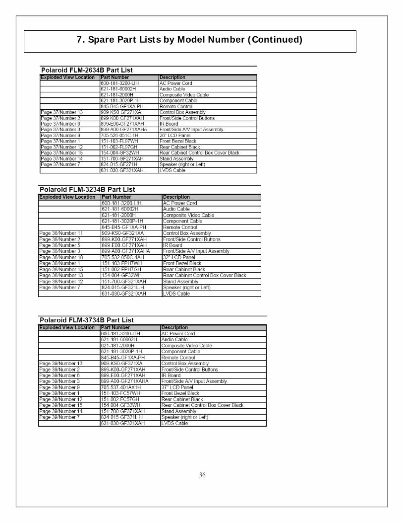
7. Spare Part Lists by Model Number (Continued)
37
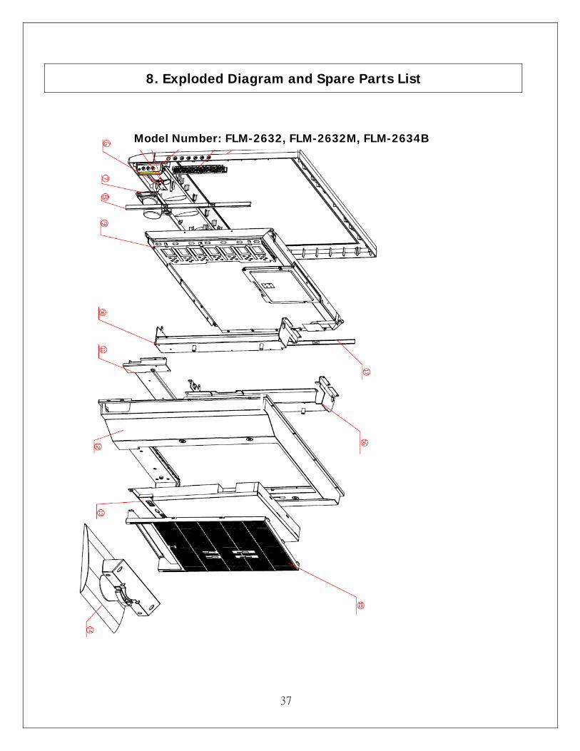
8. Exploded Diagram and Spare Parts List
Model Number: FLM-2632, FLM-2632M, FLM-2634B
37
38
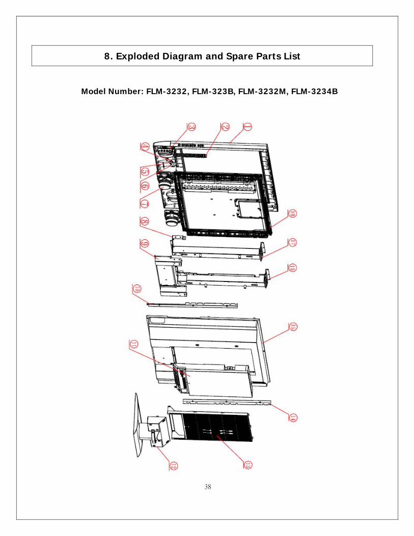
8. Exploded Diagram and Spare Parts List
Model Number: FLM-3232, FLM-323B, FLM-3232M, FLM-3234B

39
8. Exploded Diagram and Spare Parts List
Model Number: FLM-3732, FLM-373B, FLM-3732M, FLM-3734B
39
40
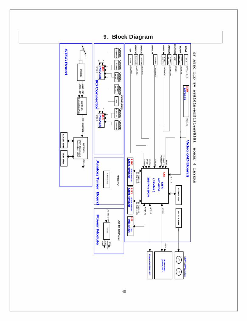
9. Block Diagram
PI5
V330
U10
H L
GP
IO-3
CV
BS
1
ATS
C B
oard
Analo
g T
uner B
oard
I/O C
onnecto
rP
ow
er M
odule
Y1/P
B1/P
R1
U11
D_R
A[1
1...0
]D
_D
Q[3
1...1
6]
R/G
/B
YP
bP
r2Y1/P
b1/P
r1VID
EO
5(H
DTV
2)
VID
EO
2C
OM
PUTERV
IDEO
6
Title
Size
Do
cum
ent N
um
ber
Rev
Da
te:
Sh
eet
of
GF L
CD
TV
B
IND
EX
& B
LO
CK
DIA
GR
AM
Pro
view E
lectron
ics (Ta
iwa
n) C
o., L
TD
.6F
, NO
.1, P
au-S
heng R
d., Y
ung-H
o C
ity,
Taip
ei C
ounty
, Taiw
an R
.O.C
.Tel: 8
86-2
-2231-6
789 F
ax: 8
86-2
-2231-5
678
C
11
2M
on
da
y, D
ece
mbe
r 19
, 200
5
+24V
LV
DS
AUDIO DAC.
AUDIO AMP.
10W
~15W
Speaker
FLASH RAM
MT5351
MT5111
TUNER
DDR RAM
DTV Backend
Decoder SOC
Demodulator
TS OUTPUT
AGC_IF
AGC_RF
VI[2
3...0
]
HD
TV
CO
MP
UTE
R
HD
MI
AC
TO
DC
Pow
er
Pow
er
+24V
Pane
l
AD
Board
+24V
AC
110~240V
M13L128168 3
88 P
in B
GA
8M
x16 S
DR
AM
8M
x16 S
DR
AM
M13L128168
IOA
[7...0
]
VID
EO
2
HD
MI
ATS
C
VG
AR
/G/B
MO
DU
LE
16M
29LV160
U9
Keypad &
IR &
LE
D
LC
D P
AN
EL
(1366x768 )
AP
[7...0
]
MT8293
U20
DA
TA
+/-[2
...0]
VI[2
3...0
]
VI[2
3...0
]
VI[2
3...0
]
Vid
eo (A
D B
oard
)NTSC
TV
NTS
C T
uner
VID
EO
5
(HD
TV
2)
YP
bP
r2
U10
U8
MT-8
202
HD
MI-D
VI
VID
EO
1V
GA
Tune
r
( Scale
r )
MTK
VID
EO
3YP
bP
r1S
-Vid
eo
Com
posite
VID
EO
3
TV
YP
bP
r1
S-V
ideo
Com
posite
Com
posite
VID
EO
4
(HD
TV
1)
Com
posite
CV
BS
0
VID
EO
4(H
DTV
1)
AV
CV
BS
1VID
EO
1
Y0/P
b0/P
r0
D_D
Q[1
5...0
]
AV
SY0/C
0
Y0/P
B0/P
R0
D_R
A[1
1...0
]
CV
BS
2
TU
_A
V1
AV
CV
BS
1
SY0/C
0
PI5
V330
U10
H L
GP
IO-3
GF ATSC LCD TV MT8202E+MT5111+MT5351 BOARD 4 LAYERS
41
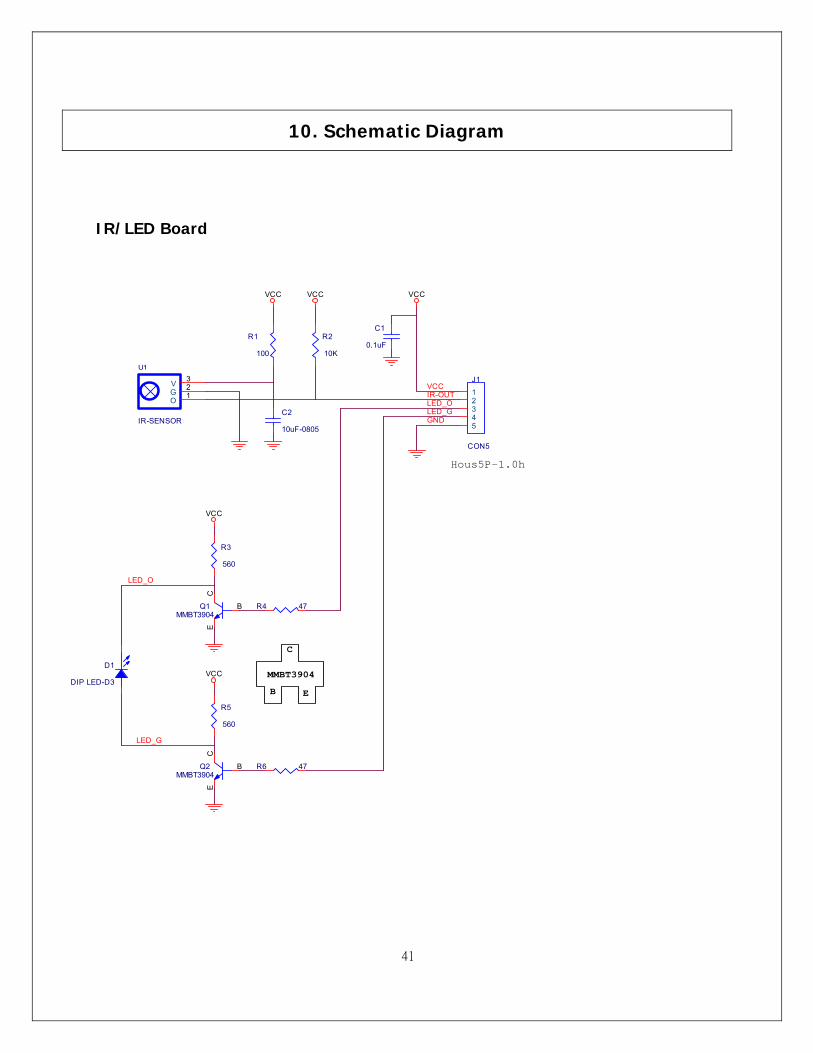
IR/LED Board
Title
Size Document Number Rev
Date: Sheet of
GF371-XU A
IR SENSOR PCB
Proview Electronics (Taiwan) Co., LTD.6F, NO.1, Pau-Sheng Rd., Yung-Ho City,Taipei County, Taiwan R.O.C.Tel: 886-2-2231-6789 Fax: 886-2-2232-4613
A
1 1Tuesday , December 20, 2005
Q1MMBT3904
B
EC
R4 47
R6 47
R3
560
LED_O
LED_G
B
MMBT3904
C
E
VCC
U1
IR-SENSOR
O 1G2V 3
VCC VCC
Q2MMBT3904
B
EC
VCC
VCC
LED_GLED_O
GND
C1
0.1uF
Hous5P-1.0h
R5
560
J1
CON5
12345
D1
DIP LED-D3
IR-OUT
VCC
R2
10K
R1
100
C2
10uF-0805
10. Schematic Diagram
42
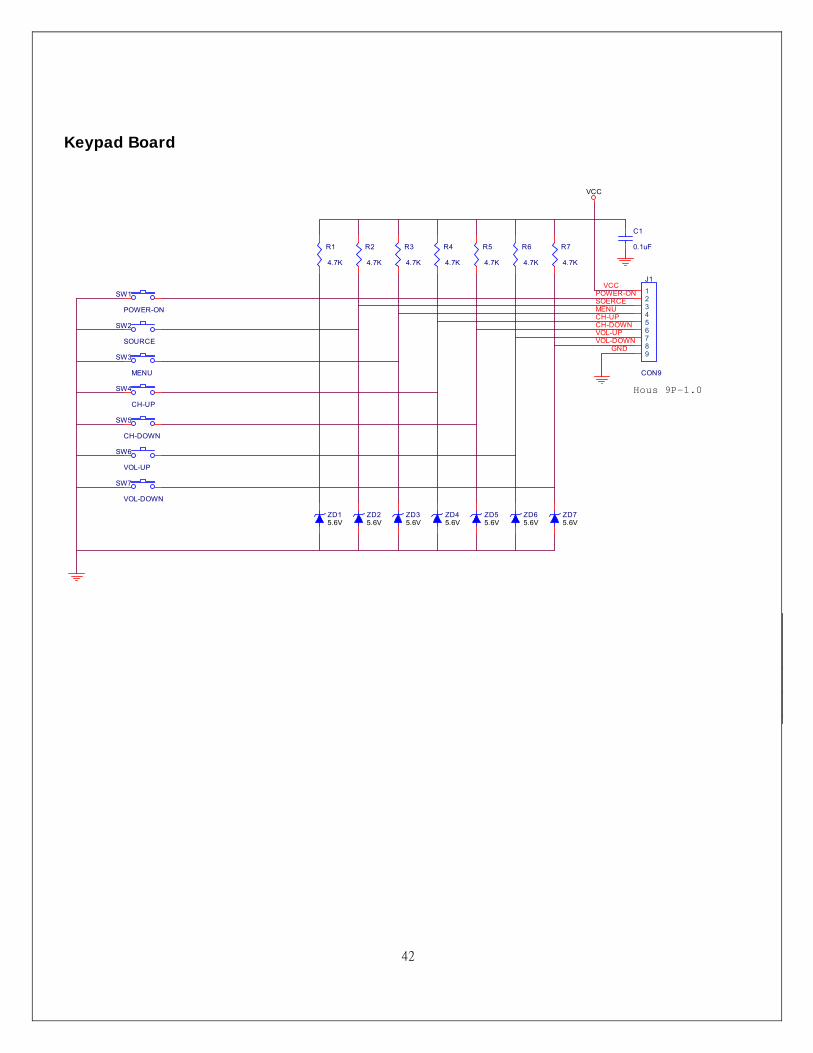
Keypad Board
ZD25.6V
ZD15.6V
SW2
SOURCE
SW3
MENU
SW4
CH-UP
SW5
CH-DOWN
SW1
POWER-ON
POWER-ONSOERCE
CH-UPMENU
CH-DOWN
Title
Size Document Number Rev
Date: Sheet of
GF371-XU A
KEYPAD PCB
Proview Electronics (Taiwan) Co., LTD.6F, NO.1, Pau-Sheng Rd., Yung-Ho City,Taipei County, Taiwan R.O.C.Tel: 886-2-2231-6789 Fax: 886-2-2232-4613
A
1 1Friday , September 30, 2005
R1
4.7K
R2
4.7K
R3
4.7K
R4
4.7K
R5
4.7K
J1
CON9
123456789
GND
Hous 9P-1.0
C1
0.1uF
VCC
VOL-DOWNVOL-UP
VCC
SW6
VOL-UP
SW7
VOL-DOWN
R6
4.7K
R7
4.7K
ZD75.6V
ZD65.6V
ZD55.6V
ZD45.6V
ZD35.6V
43
AV AUX Board
44
D-SUB 37 PIN Board
L3 FB-40-0805-700M
AF
RO
NT_A
_R
L5 FB-40-0805-700M
AF
RO
NT_A
_L
R3
75
C3
12pF
R5
75
C5
12pF
PHO
NE_A
_L
PH
ON
E_A_D
PHO
NE_A
_RU
2RC
lamp0504F
LINE1
1
GN
D2
LINE3
3LIN
E44
VCC
5LIN
E26
FR
ON
T_A_L
FR
ON
T_A_R
U3
RC
lamp0504F
LINE
11
GN
D2
LINE
33
LINE
44
VCC
5LIN
E2
6
L1FB-40-0805-700M
AL2
FB-40-0805-700MA
C1
12pF
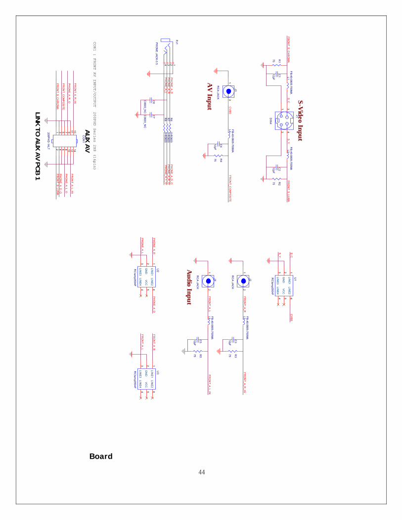
S-Video Input
S_C
FR
ON
T_S_LU
MA
R1
75
FRO
NT_S_C
HR
OM
A
R2
75
C2
12pF
FRO
NT_C
OM
POSITE
J3
RC
A JAC
K 21FR
ON
T_S_CH
RO
MA
FRO
NT_S
_LUM
A
AV
Input
FR
ON
T_A_R
_IN
J2
RC
A JAC
K 21
Audio Input
J4
RC
A JAC
K 21
FR
ON
T_A_L_IN
PHO
NE_A
_L_OPH
ON
E_A_R
_OPH
ON
E_A_D
_OR
60-R
0603R
70-R
0603R
80-R
0603
C6
C0603_N
C
C7
C0603_N
C
PHO
NE_A_D
PHO
NE_A_R
PJ1PHO
NE JA
CK-3.5 124 3
PHO
NE_A_L
Title
SizeD
ocument N
umber
Rev
Date:
Sheet
of
GF371-X
UA
AUX AV PC
B
Proview E
lectronics (Taiw
an) Co., LT
D.
6F, NO
.1, Pau-S
heng Rd., Y
ung-Ho C
ity,Taipei C
ounty, Taiwan R
.O.C
.Tel: 886-2-2231-6789 Fax: 886-2-2232-4613
B
11
Thursday, N
ovem
ber 24, 2005
GG
CY
J1DIN
4
34
12
S_Y
AUX A
V
CV
BS
CO
N1
200PH
D-14LT
131197531
1412108642
FRO
NT_A
_L_IN
PHO
NE_A_D
_O
PHO
NE_A_L_O
FRO
NT_A_R
_IN
CON1 : FRONT AV INPUT/OUTPUT
FRO
NT_C
OM
PO
SITE
PHO
NE_A
_R_O
200PHD Series 2X8 (16pin)
L4 FB-40-0805-700M
A
R4
75
C4
12pF
LINK TO
AUX A
V PCB
1
CV
BSS_C
S_Y
U1
RC
lamp0504F
LINE1
1
GN
D2
LINE3
3LIN
E44
VC
C5
LINE2
6
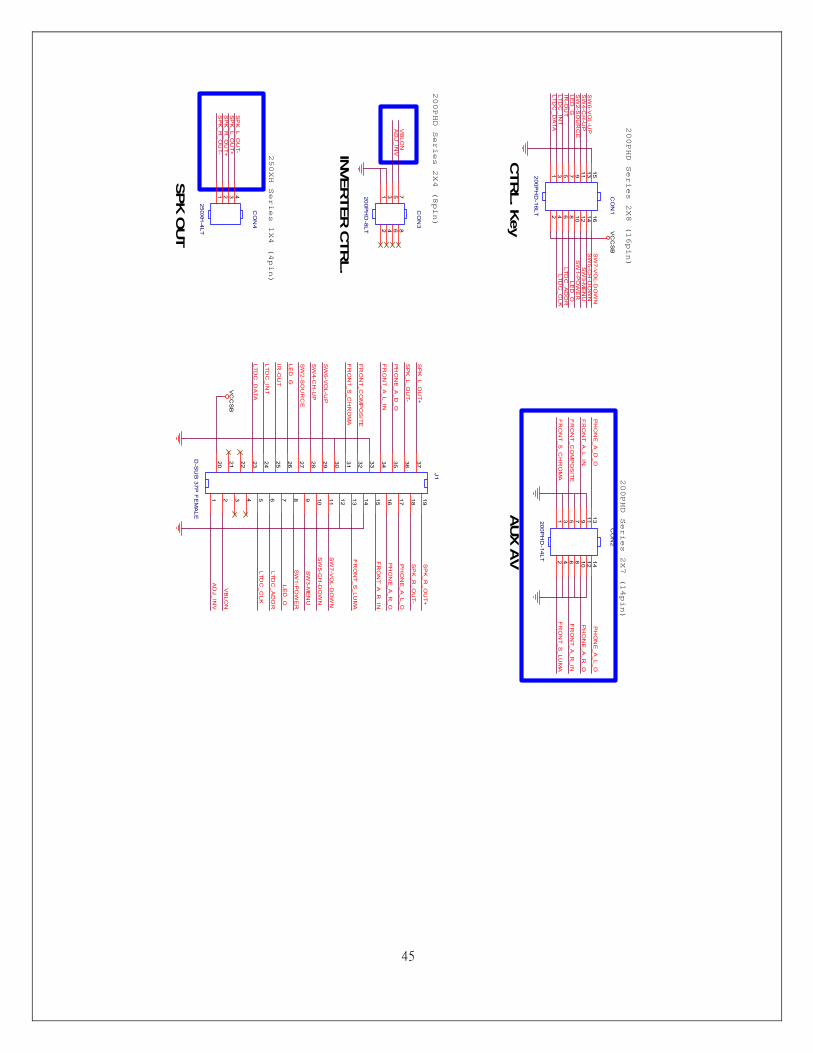
45
J1
D-S
UB
37P F
EM
ALE
1918171615141312111098765432120 21 22 23 24 25 26 27 28 29 30 31 32 33 34 35 36 37
CO
N1
200PH
D-16LT
15131197531
161412108642
250XH Series 1X4 (4pin)
200PHD Series 2X4 (8pin)
Title
Size
Docum
ent Num
berR
ev
Date:
Sheet
of
JK379-U
DA
CO
N JU
NC
T D
-SU
B 37P
in
Proview
Electronics (T
aiwan) C
o., LT
D.
6F, N
O.1, P
au-Sheng R
d., Yung-H
o City,
Taipei County, Taiw
an R.O
.C.
Tel: 886-2-2231-6789 Fax: 886-2-2232-4613
Custom
11
Friday
, Septem
ber 09, 2005
FR
ON
T_S
_LUM
A
FR
ON
T_A_L_IN
FR
ON
T_A
_R_IN
VC
CS
B
PH
ON
E_A
_R_O
AD
J_INV
VB
LON
200PHD Series 2X7 (14pin)
AUX A
V
PH
ON
E_A
_L_O
FR
ON
T_S
_LUM
A
FR
ON
T_A
_R_IN
PH
ON
E_A
_R_O
FR
ON
T_S_C
HR
OM
A
FR
ON
T_CO
MP
OS
ITE
FR
ON
T_A_L_IN
PH
ON
E_A
_D_O
CO
N2
200PH
D-14LT
131197531
1412108642
LTDC
_DA
TALTD
C_C
LKLTD
C_IN
T
SW
2-SO
UR
CE
IR-O
UT
LTDC
_AD
DR
LED
_GLE
D_O
SW
6-VO
L-UP
SW
5-CH
-DO
WN
SW
3-ME
NU
SW
7-VO
L-DO
WN
SW
4-CH
-UP
SW
1-PO
WE
R
SP
K_R
_OU
T+S
PK
_L_OU
T+
SP
K_R
_OU
T-
SP
K_L_O
UT-
AD
J_IN
VV
BLO
N
SP
K_R
_OU
T+
SP
K_R
_OU
T-
SP
K_L_O
UT
+
SP
K_L_O
UT
-P
HO
NE
_A_L_O
PH
ON
E_A
_D_O
CO
N3
200PH
D-8LT
7531
8642
FR
ON
T_CO
MP
OS
ITE
FR
ON
T_S_C
HR
OM
A
CTR
L. K
ey
INVER
TER
CTR
L.
CO
N4
250XH-4LT
1 2 3 4
SPK
OUT
200PHD Series 2X8 (16pin)
LTDC
_CLK
SW
3-ME
NU
LED
_OLTD
C_A
DD
R
SW
5-CH
-DO
WN
SW
1-PO
WE
R
SW
7-VO
L-DO
WN
SW
4-CH
-UP
SW
2-SO
UR
CE
LED
_GIR
-OU
T
LTD
C_D
ATA
LTD
C_IN
T
SW
6-VO
L-UP
VC
CS
B

46
11. PCB Layout Diagram Keypad Board (Component Side Top)
Keypad Board (Component Side Bottom)
IR/LED Board (Component Side Top)
IR/LED Board (Component Side Bottom)
47
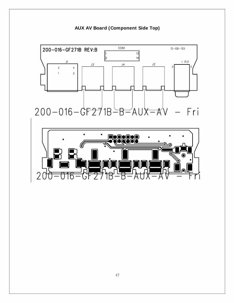
AUX AV Board (Component Side Top)
48
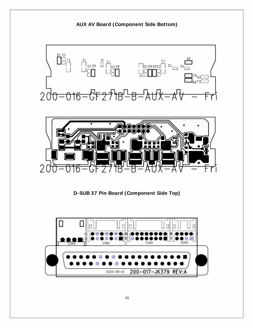
AUX AV Board (Component Side Bottom)
D-SUB 37 Pin Board (Component Side Top)
49
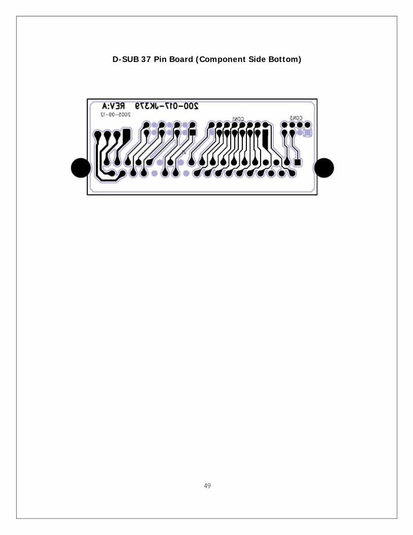
D-SUB 37 Pin Board (Component Side Bottom)