Polarization and Modulation of light I Production ... - Piazza
32
ECE 325 OPTOELECTRONICS Ahmed Farghal, Ph.D. ECE, Menoufia University Lecture 6 Polarization and Modulation of light I March 20, 2019 Kasap–6.1, 6.2, 6.3 and 6.4
Transcript of Polarization and Modulation of light I Production ... - Piazza

ECE 325 OPTOELECTRONICS
Ahmed Farghal, Ph.D. ECE, Menoufia University
Lecture 6
Polarization and Modulation of light I
March 20, 2019
Kasap–6.1, 6.2, 6.3 and 6.4
Production of polarized light
1. By Reflection: Brewster’s Law
2. By Refraction: Malus Law
3. By selective absorption: Dichroic material
4. By double refraction:
-Nicol Prism
- Wave plates

EC
E 3
25
S
pri
ng
20
19
D
r. A
hm
ed
F
arg
ha
l L
ec
ture
6
Polarization
2
Polarization: the 𝐄-field vector behavior in the EM wave as it
propagates through a medium.
Linearly polarized EM wave: the field oscillations of 𝐄-field at a
given point at all times are confined to a well defined line.
Unpolarized light beam: light beam has waves with 𝐄 -field
propagating with random orientation ⊥ to 𝒛.
The field vector for a plane wave propagating in 𝑧 with
oscillations along a line in the 𝑥𝑦 plane is
The electric field E in the wave at any space and time
location can be found by adding Ex and Ey vectorially.
𝒙 and 𝒚 are the
unit vectors
along x and y
= phase difference between Ey and Ex; can
arise if one of the components is delayed
(retarded)
Both Ex and Ey can individually be described
by a wave equation which must have the same
angular frequency and wavenumber k.
However, we must include a phase difference
between the two
Unpolarized light (natural light)
..\VIP VIP next year P272fall10-23 Polarization.pdf مهم جدا جدا

EC
E 3
25
S
pri
ng
20
19
D
r. A
hm
ed
F
arg
ha
l L
ec
ture
6
Linearly Polarized Light
3
Linearly polarized light beam with E-field oscillations at −45∘ to 𝑥-
axis is obtained by choose 𝐸𝑥𝑜 = 𝐸𝑦𝑜 and 𝜙 = ±180°.
Vector amplitude which is at − 45° to the 𝑥-axis
describes the propagation of 𝐸𝑜 at − 45° to 𝑥-axis along the 𝑧-direction.
unit vectors
along 𝑥 and 𝑦
Use 𝜙 = 𝜋
(a) A linearly polarized wave has its electric field oscillations defined along a line
perpendicular to the direction of propagation, z. The field vector E and z define a plane of
polarization. (b) The E-field oscillations are contained in the plane of polarization. (c) A
linearly polarized light at any instant can be represented by the superposition of two fields
Ex and Ey with the right magnitude and phase
created
between the 𝑘
and 𝐄 vectors. Linearly polarized 𝐄 -field
oscillations create a plane of
polarization between the 𝑘 and 𝐄
vectors. Ex and Ey have the same magnitude
but they are out of phase by 180.
S.O. Kasap, Optoelectronics and Photonics: Principles and Practices, Second Edition, © 2013 Pearson Education
..\..\3- Textbook\Optics-Global-Edition.pdf Chapter 8

EC
E 3
25
S
pri
ng
20
19
D
r. A
hm
ed
F
arg
ha
l L
ec
ture
6
4
Circularly Polarized Light
If the magnitude of the field vector E remains constant but its end
point at a given location on z traces out a circle by rotating in a
clockwise sense with time, as observed by the receiver of the wave,
then the wave is said to be right circularly polarized.
If the rotation of the tip of E is counterclockwise, the wave is said
to be left circularly polarized.
A right circularly polarized light. The field vector E is always at
right angles to z, rotates clockwise around z with time, and traces
out a full circle over one wavelength of distance propagated.
Right circular polarization - clockwise rotation of the E-field as it
propagates along 𝑘. (the magnitude of field vector E remains
constant).
Left circular polarization - counter clockwise rotation of the E-
field as it propagates along 𝑘.
Animation of left-handed/counter-clockwise circularly polarized light. (Left-handed as viewed from the receiver.
https://en.wikipedia.org/wiki/Polarizer
S.O. Kasap, Optoelectronics and Photonics: Principles and Practices, Second Edition, © 2013 Pearson Education

EC
E 3
25
S
pri
ng
20
19
D
r. A
hm
ed
F
arg
ha
l L
ec
ture
6
Circularly Polarized Light
5
⇒ represent a circle
Assume that 𝜙 = 90° and 𝐸𝑥𝑜 = 𝐸𝑦𝑜 = 𝐴. Then
A right circularly polarized light that is traveling along z (out of paper).
The field vector E is always at right angles to z, rotates clockwise around z with
time, and traces out a full circle over one wavelength of distance propagated.
S.O. Kasap, Optoelectronics and Photonics: Principles and Practices, Second Edition, © 2013 Pearson Education

EC
E 3
25
S
pri
ng
20
19
D
r. A
hm
ed
F
arg
ha
l L
ec
ture
6
Linear and Circular Polarization
6
For simplicity, 𝐸𝑦𝑜 = 1 has been taken and the corresponding 𝐸𝑥𝑜
and 𝜙 are shown.
Linearly polarized light Circularly polarized light
right circularly left circularly
as seen when the wave directly
approaches a viewer
Ex = Exocos(t - kz )
Ey = Eyocos(t - kz + )
S.O. Kasap, Optoelectronics and Photonics: Principles and Practices, Second Edition, © 2013 Pearson Education
EC
E 3
25
S
pri
ng
20
19
D
r. A
hm
ed
F
arg
ha
l L
ec
ture
6
Linear and Elliptical Polarization
7
Assume that the magnitude of one vector component in E is larger
then the other, i.e., 𝑬𝒙𝒐 ≠ 𝑬𝒚𝒐.
Instead of a circle, the wave generates an ellipse as it propagates
along 𝑘 in the 𝑧 direction.
(a) Linearly polarized light with 𝐸𝑦𝑜 = 2𝐸𝑥𝑜 and 𝜙 = 0. (b) When 𝜙 = 𝜋/4, the light is
right elliptically polarized with a tilted major axis. (c) When 𝜙 = 𝜋/2, the light is right
elliptically polarized.
If 𝐸𝑥𝑜 and 𝐸𝑦𝑜 were equal, this would be right circularly polarized light.
S.O. Kasap, Optoelectronics and Photonics: Principles and Practices, Second Edition, © 2013 Pearson Education

EC
E 3
25
S
pri
ng
20
19
D
r. A
hm
ed
F
arg
ha
l L
ec
ture
6
A right circularly polarized wave has Exo = Eyo = A (an amplitude),
and = /2. This means that,
Ex = Acos(t - kz )
and Ey = -Asin(t - kz )
When 𝐸𝑥𝑜 = 𝐸𝑦𝑜 = 𝐴 and the phase difference is other than 0, or
/2, i.e. ±𝜋/4 or ±3𝜋/4 , the resultant wave is elliptically polarized
and the tip of the vector in the figure traces out an ellipse.
Circular and Elliptical Polarization
Elliptic light can also be obtained when 𝐸𝑥𝑜 = 𝐸𝑦𝑜 and the phase difference is
± 𝜋/4 or ±3𝜋/4, etc.
8 S.O. Kasap, Optoelectronics and Photonics: Principles and Practices, Second Edition, © 2013 Pearson Education
EC
E 3
25
S
pri
ng
20
19
D
r. A
hm
ed
F
arg
ha
l L
ec
ture
6
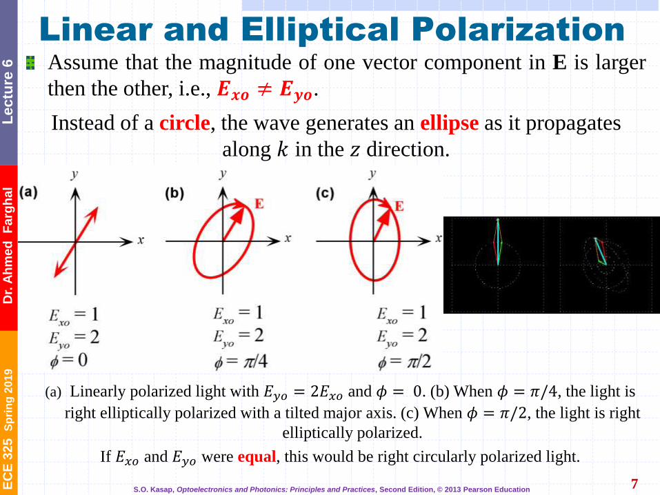
Example: Elliptical and Circular Polarization
9
Show that if the magnitudes, 𝑬𝒙𝒐 and 𝑬𝒚𝒐, are different and the
phases difference is 𝟗𝟎°, that the wave is elliptically polarized
Further, at 𝑧 = 0 and at ω𝑡 = 0, 𝐸 = 𝐸𝑥 = 𝐸𝑥𝑜 . Moreover, at
ω𝑡 = 𝜋 2 , 𝐸 = 𝐸𝑦 = −𝐸𝑦𝑜
Thus the field rotates in a clockwise position: Right
Elliptically Polarized
Equation for an ellipse if the denominators do not equal,
𝐸𝑥𝑜 ≠ 𝐸𝑦𝑜. Wheares 𝐸𝑥𝑜 = 𝐸𝑦𝑜 ⇒ equation of circle.

EC
E 3
25
S
pri
ng
20
19
D
r. A
hm
ed
F
arg
ha
l L
ec
ture
6
Polarizers
10
The wire grid-acts as a polarizer
A linear polarizer allows only field oscillations along a
particular/preferred direction, called the transmission axis (TA) to
pass through.
Transmission axis (TA)
There are many types of polarizers
The transmitted light is polarized based on the orientation of the
polarizing medium.
Polaroid sheets are common examples of linear polarizers.
Wire Grid Polarizer The polarization of electromagnetic waves describes the orientation of wave oscillations perpendicular to the direction of propagation. A wire grid polarizer is an array of thin metal lines/wires closely spaced sitting on top of a transparent substrate. It works as an absorptive polarizer and only passes through light oscillating perpendicular to the wires. Light oscillating in parallel with the wires will generate electron movement along the wires in response to the oscillating field. The electron movement creates a travelling wave cancelling the incoming waves oscillating parallel to the wires and reflects it in the same manner as a thin metal sheet. The components of the incoming wave having a polarization parallel to the wires are thus reflected with some loss due to Joule heating caused by electron movement in the wires. Since only a specific polarization is allowed through the wire grid polarizer, the outgoing wave will have a single linear polarization.
Most light sources emit unpolarized
light. A common way of producing
polarized light is by the use of polarizers.
http://hyperphysics.phy-astr.gsu.edu/hbase/phyopt/polabs.html
Commercial Polaroid H-Sheet:
•It’s a dichroic sheet polarizer.
•An ideal H-sheet would transmit 50% of
the incident natural light and is designated
HN-50.
•In practice, due to loss, the H-sheet might
be labeled HN-46, HN-38, HN-32, and HN-
22 with the number indicating the
percentage of natural light transmitted
through the H-sheet.
Polarizers absorb one component of the polarization but not the other. The input is natural light, the output is polarized light (linear, circular, elliptical). They work by dichroism, birefringence, reflection, or scattering.
Wire-grid polarizers (I) [dichroism]
• Mainly used in the IR and longer wavelengths
• Grid of parallel conducting wires with a spacing comparable to the wavelength of observation
• Electric field vector parallel to the wires is attenuated because of currents induced in the wires
EC
E 3
25
S
pri
ng
20
19
D
r. A
hm
ed
F
arg
ha
l L
ec
ture
6
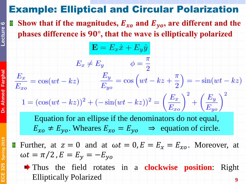
Polaroid Sheets
11
Polaroid sheet
eg aligned PVA molecules
E cos
E sin
E cos
E-field component
aligned with long
axis of molecule is
absorbed
E
1) Intensity of unpolarized light incident on linear polarizer is reduced by half . I1= I0 / 2
Made by heating and stretching a sheet of PVA laminated to a supporting
sheet of cellulose acetate treated with iodine solution (H-type polaroid).
Invented in 1928.

EC
E 3
25
S
pri
ng
20
19
D
r. A
hm
ed
F
arg
ha
l L
ec
ture
6
Malus’s Law
12
Combining two polarizers
1st polarizer generates initial polarization.
2nd polarizer, the analyzer is used to measure the degree of
polarization of the 1st polarizer by reducing field intensity as a
function of off axis polarization by the analyzer.
Malus’s law relates the intensity of a linearly polarized light passing
through a polarizer to the angle between the TA and the E vector.
𝜃 = 0 (E parallel to TA2) ⇒
maximum irradiance condition
Randomly polarized light is incident on a Polarizer 1 with a transmission axis TA1. Light emerging
from Polarizer 1 is linearly polarized with E along TA1, and becomes incident on Polarizer 2 (called
the analyzer) with a transmission axis TA2 at an angle to TA1. A detector measures the intensity
of the incident light. TA1 and TA2 are normal to the light direction.
Etienne-Louis Malus
1775-1812
S.O. Kasap, Optoelectronics and Photonics: Principles and Practices, Second Edition, © 2013 Pearson Education
2cos )0(II
Unpolarized light
2cos2 o
o
III

EC
E 3
25
S
pri
ng
20
19
D
r. A
hm
ed
F
arg
ha
l L
ec
ture
6
Optically Isotropic Materials
13
Optically isotropic materials have isotropic crystal structures:
Generate uniform polarization along all three principle axis.
Have uniform refractive indices for all incident angles.
Electronic polarization in a
medium depends on crystal
orientation.
Most noncrystalline materials such as liquids
and glasses, and all cubic crystals are optically
isotropic
Sodium chloride (halite) crystal
The refractive index is the same in all directions
for all polarizations of the field.
Photo by SK
Most noncrystalline materials such as glasses and liquids, and all cubic crystals are
optically isotropic, that is the refractive index is the same in all directions.
S.O. Kasap, Optoelectronics and Photonics: Principles and Practices, Second Edition, © 2013 Pearson Education
We can describe light propagation in terms of three refractive indices,
called principal refractive indices n1, n2 and n3, along three mutually
orthogonal directions in the crystal, say x, y and z called principal axes.
Principal Refractive Indices
EC
E 3
25
S
pri
ng
20
19
D
r. A
hm
ed
F
arg
ha
l L
ec
ture
6
Optical Anisotropy
14
A line viewed through a cubic sodium chloride (halite) crystal
(optically isotropic) and a calcite crystal (optically anisotropic)
In the same manner that crystals have unit vectors
representing principle axes, their permittivity and
refractive indices also will also have principle indices
indicating the different refraction characteristics at
different angles of incidence, i.e., 𝑛1, 𝑛2, and 𝑛3.
An optic axis of a crystal is a direction in which a ray of transmitted
light suffers no birefringence (double refraction). An optical axis is a
direction rather than a single line: all rays that are parallel to that
direction exhibit the same lack of birefringence.[1]
Crystals may have a single optic axis, in which case they are uniaxial,
or two different optic axes, in which case they are biaxial. Non-
crystalline materials generally have no birefringence and thus, no
optic axis. A uniaxial crystal (e.g. calcite, quartz) is isotropic within the
plane orthogonal to the optic axis of the crystal.
Knowledge of the optical properties of any crystal used for optical devices is important for design and analysis purposes. Furthermore, in an electrooptic crystal the presence of an electric field may produce changes in these properties due to the electrooptic effect. This influence induces perturbations in the impermeability tensor [1/𝑛2]. In the absence of any disturbance, the principal axes of the crystal are the standard orthogonal dielectric axes x, y, and z,and the refractive indices corresponding to polarizations along these directions are nx, ny,and n,, respectively. However, with the application of an electric field, the dielectric axes are changed, as are the corresponding indices of refraction.
تباين
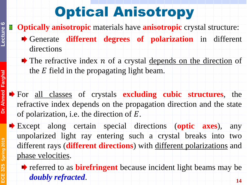
Optically anisotropic materials have anisotropic crystal structure:
Generate different degrees of polarization in different
directions
The refractive index 𝑛 of a crystal depends on the direction of
the 𝐸 field in the propagating light beam.
For all classes of crystals excluding cubic structures, the
refractive index depends on the propagation direction and the state
of polarization, i.e. the direction of 𝐸.
Except along certain special directions (optic axes), any
unpolarized light ray entering such a crystal breaks into two
different rays (different directions) with different polarizations and
phase velocities.
referred to as birefringent because incident light beams may be
doubly refracted.

EC
E 3
25
S
pri
ng
20
19
D
r. A
hm
ed
F
arg
ha
l L
ec
ture
6
When we view an image through a calcite crystal, an optically
anisotropic crystal, we see two images, each constituted by light of
different polarization passing through the crystal, whereas there is
only one image through an optically isotropic crystal as depicted in
the figure. Optically anisotropic crystals are called birefringent
because an incident light beam may be doubly refracted.
Birefringence
A line viewed through a cubic sodium chloride (halite) crystal (optically isotropic) and a calcite
crystal (optically anisotropic).
sodium chloride
(halite) crystal
(optically
isotropic)
calcite crystal
(optically
anisotropic)
15
Photo by S. Kasap
Crystal polarizers (I)
[birefringence]
• Optically anisotropic crystals
• Mechanical model:
• the crystal is anisotropic, which means that the electrons are bound with different ‘springs’ depending on the orientation
• different ‘spring constants’ gives different propagation speeds, therefore different indices of refraction, therefore 2 output beams
EC
E 3
25
S
pri
ng
20
19
D
r. A
hm
ed
F
arg
ha
l L
ec
ture
6
We can describe light propagation in terms of three refractive indices,
called principal refractive indices n1, n2 and n3, along three mutually
orthogonal directions in the crystal, say x, y and z called principal axes.
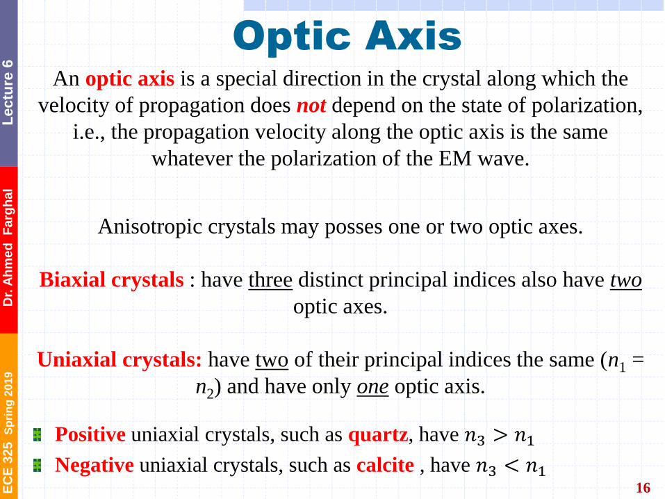
Optic Axis An optic axis is a special direction in the crystal along which the
velocity of propagation does not depend on the state of polarization,
i.e., the propagation velocity along the optic axis is the same
whatever the polarization of the EM wave.
Anisotropic crystals may posses one or two optic axes.
Biaxial crystals : have three distinct principal indices also have two
optic axes.
Uniaxial crystals: have two of their principal indices the same (n1 =
n2) and have only one optic axis.
16
Positive uniaxial crystals, such as quartz, have 𝑛3 > 𝑛1
Negative uniaxial crystals, such as calcite , have 𝑛3 < 𝑛1
Uniaxial crystals, such as quartz, that have n3 >
n1 are called positive, and those such as calcite
that have n3 < n1 are called negative uniaxial
crystals.
EC
E 3
25
S
pri
ng
20
19
D
r. A
hm
ed
F
arg
ha
l L
ec
ture
6
Uniaxial Crystals
17
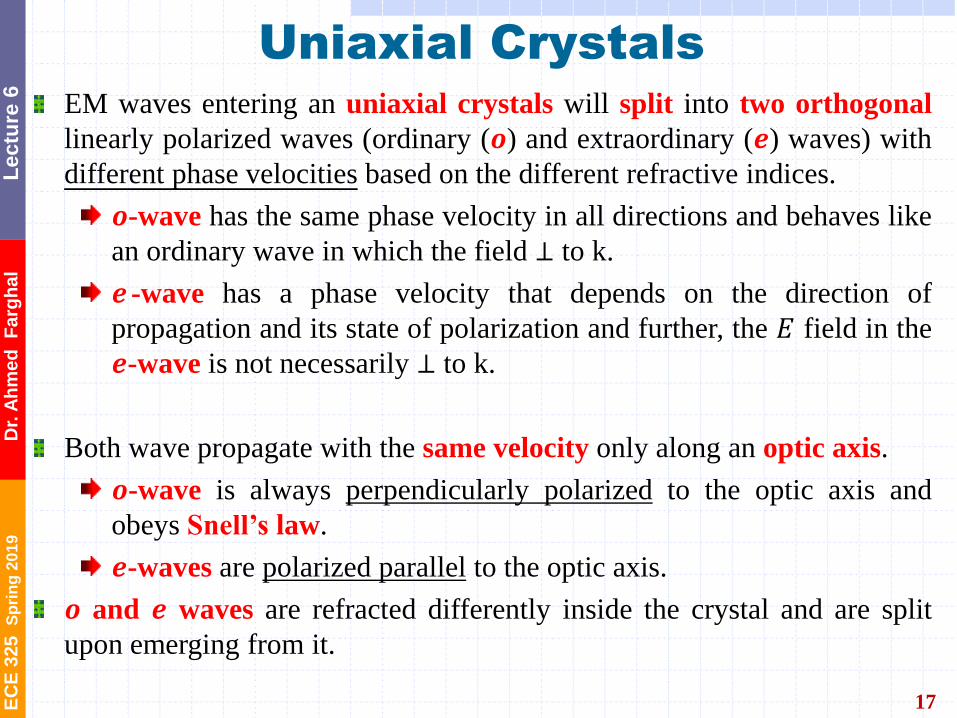
EM waves entering an uniaxial crystals will split into two orthogonal
linearly polarized waves (ordinary (𝒐) and extraordinary (𝒆) waves) with
different phase velocities based on the different refractive indices.
𝒐-wave has the same phase velocity in all directions and behaves like
an ordinary wave in which the field ⊥ to k.
𝒆 -wave has a phase velocity that depends on the direction of
propagation and its state of polarization and further, the 𝐸 field in the
𝒆-wave is not necessarily ⊥ to k.
Both wave propagate with the same velocity only along an optic axis.
𝒐-wave is always perpendicularly polarized to the optic axis and
obeys Snell’s law.
𝒆-waves are polarized parallel to the optic axis.
𝒐 and 𝒆 waves are refracted differently inside the crystal and are split
upon emerging from it.
EC
E 3
25
S
pri
ng
20
19
D
r. A
hm
ed
F
arg
ha
l L
ec
ture
6
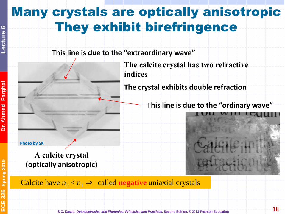
Many crystals are optically anisotropic
They exhibit birefringence
18
The calcite crystal has two refractive
indices
A calcite crystal
(optically anisotropic)
The crystal exhibits double refraction
This line is due to the “ordinary wave”
This line is due to the “extraordinary wave”
Photo by SK
Biaxial crystals: crystals with 3 distinct principle axis and two optic axis.
Uniaxial crystals: crystals with 2 principle axis (𝑛1 = 𝑛2) and 1 optical axis.
Positive uniaxial crystals, such as quartz, have 𝑛3 > 𝑛1
Negative uniaxial crystals, such as calcite , have 𝑛3 < 𝑛1
Calcite have n3 < n1 ⇒ called negative uniaxial crystals
S.O. Kasap, Optoelectronics and Photonics: Principles and Practices, Second Edition, © 2013 Pearson Education

EC
E 3
25
S
pri
ng
20
19
D
r. A
hm
ed
F
arg
ha
l L
ec
ture
6
Uniaxial Crystals
19
Images viewed through a calcite crystal have orthogonal polarizations.
Two polaroid analyzers are placed with their transmission axes, along the long edges, at right angles to each other.
The 𝒐-wave, undeflected, goes through the left polarizer whereas the 𝒆-wave, deflected, goes through the right polarizer. The two waves
therefore have orthogonal polarizations.
Images viewed through a calcite crystal have orthogonal polarizations. Two polaroid analyzers are
placed with their transmission axes, along the long edges, at right angles to each other. The ordinary
ray, undeflected, goes through the left polarizer whereas the extraordinary wave, deflected, goes
through the right polarizer. The two waves therefore have orthogonal polarizations
“ordinary wave” Left polarizer
“extraordinary wave” Right polarizer
S.O. Kasap, Optoelectronics and Photonics: Principles and Practices, Second Edition, © 2013 Pearson Education

EC
E 3
25
S
pri
ng
20
19
D
r. A
hm
ed
F
arg
ha
l L
ec
ture
6
20
Optically isotropic n = no Glass (crown) 1.510
Diamond 2.417
Fluorite (CaF2) 1.434
Uniaxial - Positive 𝑛1(𝑛𝑜) 𝑛3(𝑛𝑒)
Ice 1.309 1.3105
Quartz 1.5442 1.5533
Rutile (TiO2) 2.616 2.903
Uniaxial - Negative 𝑛1(𝑛𝑜) 𝑛3(𝑛𝑒)
Calcite (CaCO3) 1.658 1.486
Tourmaline 1.669 1.638
Lithium niobate
(LiNbO3)
2.29 2.20
Biaxial n1 n2 n3
Mica
(muscovite)
1.5601 1.5936 1.5977
Principal refractive indices of some optically
isotropic and anisotropic crystals
(near 589 nm, yellow Na-D line)
Positive uniaxial crystals, such as quartz, have 𝑛3(𝑛𝑒) > 𝑛1(𝑛𝑜)
Negative uniaxial crystals, such as calcite , have 𝑛3 𝑛𝑒 < 𝑛1(𝑛𝑜)
S.O. Kasap, Optoelectronics and Photonics: Principles and Practices, Second Edition, © 2013 Pearson Education
𝑛3(𝑛𝑒) > 𝑛1(𝑛𝑜)
𝑛3 𝑛𝑒 < 𝑛1(𝑛𝑜)
EC
E 3
25
S
pri
ng
20
19
D
r. A
hm
ed
F
arg
ha
l L
ec
ture
6
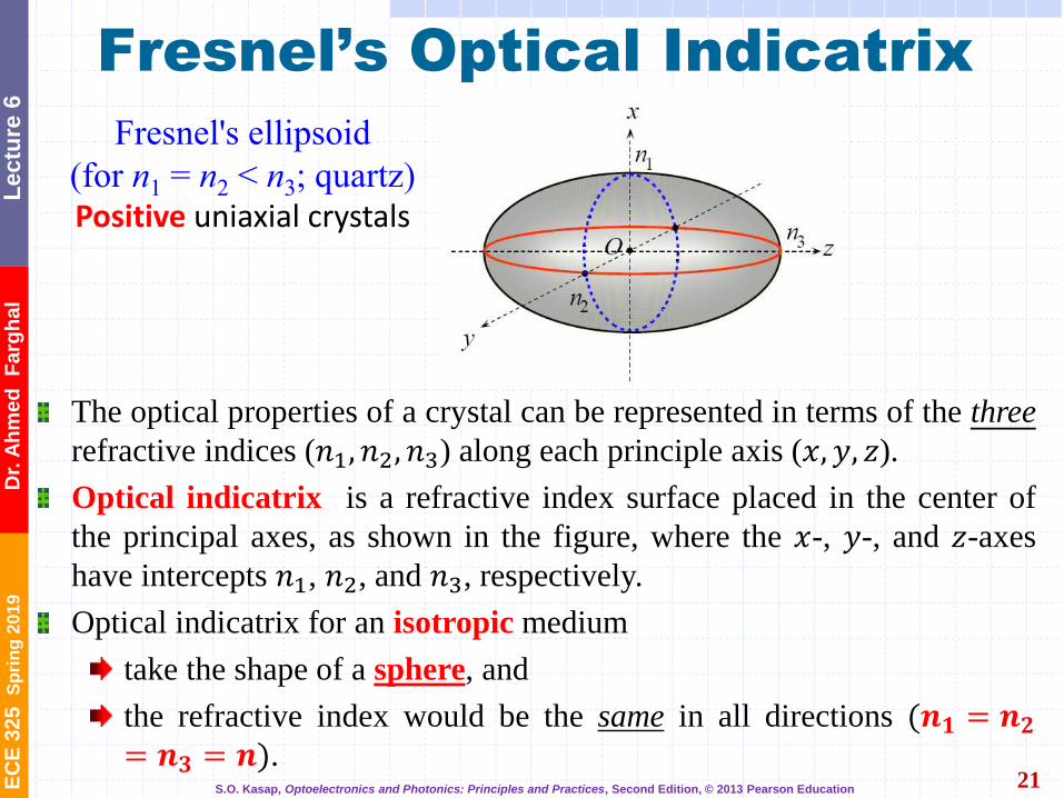
Fresnel’s Optical Indicatrix
21
The optical properties of a crystal can be represented in terms of the three
refractive indices (𝑛1, 𝑛2, 𝑛3) along each principle axis (𝑥, 𝑦, 𝑧).
Optical indicatrix is a refractive index surface placed in the center of
the principal axes, as shown in the figure, where the 𝑥-, 𝑦-, and 𝑧-axes
have intercepts 𝑛1, 𝑛2, and 𝑛3, respectively.
Optical indicatrix for an isotropic medium
take the shape of a sphere, and
the refractive index would be the same in all directions (𝒏𝟏 = 𝒏𝟐= 𝒏𝟑 = 𝒏).
𝑛1 = 𝑛2 < 𝑛3; quartz
The refractive index associated
with a particular EM wave in a
crystal can be determined by
Fresnel’s refractive index
ellipsoid called the optical
indicatrix.
Fresnel's ellipsoid
(for n1 = n2 < n3; quartz) Positive uniaxial crystals
S.O. Kasap, Optoelectronics and Photonics: Principles and Practices, Second Edition, © 2013 Pearson Education
EC
E 3
25
S
pri
ng
20
19
D
r. A
hm
ed
F
arg
ha
l L
ec
ture
6
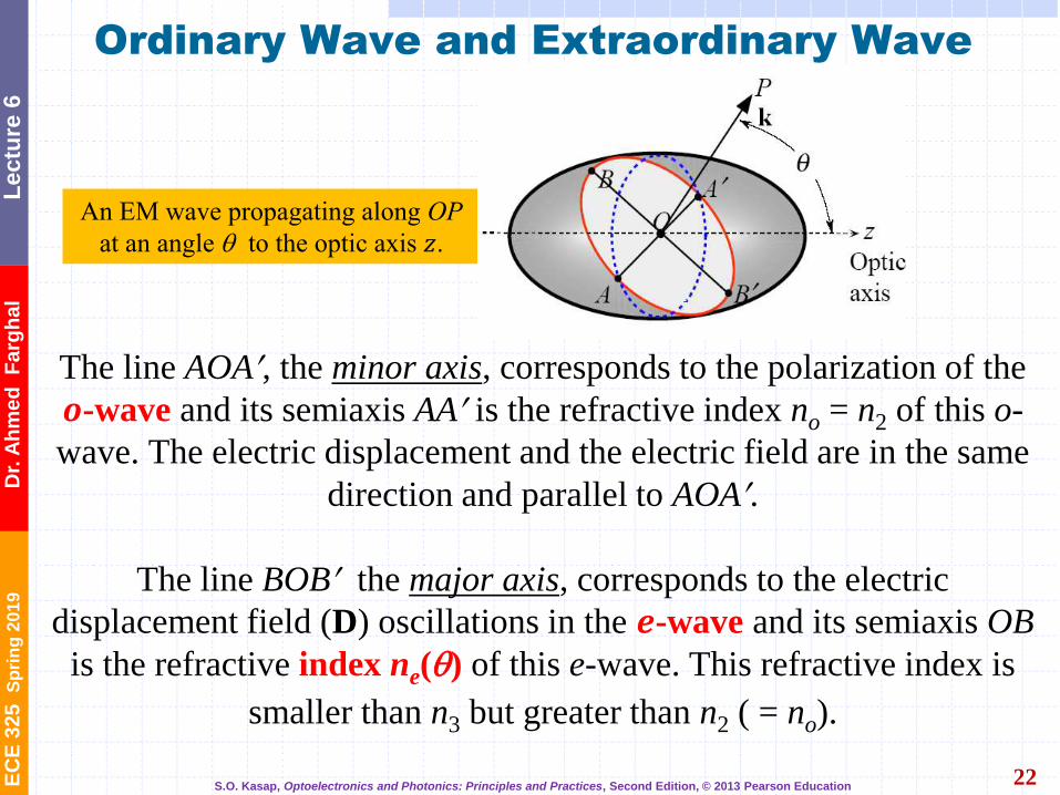
Ordinary Wave and Extraordinary Wave
22
An EM wave propagating along OP
at an angle to the optic axis 𝑧.
The line AOA, the minor axis, corresponds to the polarization of the
𝒐-wave and its semiaxis AA is the refractive index no = n2 of this o-
wave. The electric displacement and the electric field are in the same
direction and parallel to AOA.
The line BOB the major axis, corresponds to the electric
displacement field (D) oscillations in the 𝒆-wave and its semiaxis OB
is the refractive index ne() of this e-wave. This refractive index is
smaller than n3 but greater than n2 ( = no).
S.O. Kasap, Optoelectronics and Photonics: Principles and Practices, Second Edition, © 2013 Pearson Education
Ee-wave is orthogonal to k only when the e-wave propagates
along one of the principal axes.
In birefringent crystals it is usual to take ray direction as the
direction of energy flow, that is the direction of the Poynting
vector (S). The Ee-wave is then orthogonal to the ray direction.
For the o-wave, the wavefront propagation direction k is the
same as the energy flow direction S.
For the e-wave, however, the wavefront propagation direction
k is not the same as the energy flow direction S.
The Extraordinary Wave

EC
E 3
25
S
pri
ng
20
19
D
r. A
hm
ed
F
arg
ha
l L
ec
ture
6
23
Ordinary Wave and Extraordinary Wave
When the e-wave is traveling along the y-axis, or along the x-axis,
ne( ) = n3 = ne and the e-wave has its slowest phase velocity.
Along any OB direction that is at an angle to the optic axis, the
e-wave has a refractive index ne() given by
2
2
2
2
2
sincos
)(
1
eoe nnn
+
Clearly, for = 0, ne(0) = no and for = 90, ne(90) = ne.
The electric field Ee-wave of the e-wave is orthogonal to that of the o-
wave, and it is in the plane determined by k and the optic axis.
along the optic axis normal to optic axis

EC
E 3
25
S
pri
ng
20
19
D
r. A
hm
ed
F
arg
ha
l L
ec
ture
6
O-Wave and E-Wave Propagation
24
When 𝒆-wave is traveling along the 𝑧-axis (optic axis), = 0, as
in Fig. (a) ⇒ 𝑛𝑒 = 𝑛𝑜 .
All waves traveling along the optic axis have the same phase velocity
whatever their polarization.
When the 𝒆-wave is traveling along the 𝑦-axis (or along the 𝑥-axis)
⇒ 𝑛𝑒(𝜃 = 90°) = 𝑛3 = 𝑛𝑒 and the 𝑒-wave has its slowest phase
velocity as shown in Fig. (b).
Eo = Eo-wave and Ee = Ee-wave (a) Wave propagation along the optic axis. (b)
Wave propagation normal to optic axis
(a) Wave propagation along the
optic axis. (b) Wave propagation normal
to optic axis
Eo = Field of o-wave = Eo-wave
Ee = Field of e-wave = Ee-wave
Wave Propagation in a Uniaxial Crystal
S.O. Kasap, Optoelectronics and Photonics: Principles and Practices, Second Edition, © 2013 Pearson Education
Convention

EC
E 3
25
S
pri
ng
20
19
D
r. A
hm
ed
F
arg
ha
l L
ec
ture
6
Birefringence of Calcite (CaCO3)
25
Unpollarized light that is off the optic axis entering the structure is broken into an 𝒐- and 𝒆-wave propagating through at different angles and mutually orthogonal polarizations.
o-wave has its field oscillations ⊥ the optic axis (out of the paper 𝐸⊥). It obeys Snell’s law, i.e., it enters the crystal undeflected.
𝒆-wave polarization is in the plane of the paper, indicated as 𝐸∥. It travels with a different velocity and diverges from the 𝑜-wave.
Angle of refraction of the 𝒆-wave ≠ 0 as required by Snell’s law.
Both waves propagate at different velocities and emerge propagating in the same direction but at orthogonal polarizations.
An EM wave that is off the optic axis of a calcite crystal splits into two waves called ordinary and extraordinary waves. These waves have orthogonal polarizations and travel with different velocities. The o-wave has a polarization that is always perpendicular to the optical axis.
In geometry, a rhombohedron is a three-
dimensional figure like a cube, except that
its faces are not squares but rhombi. It is a
special case of a parallelepiped where all edges are the same length. crystal orientation is
a rhombohedron
(parallelogram with
78.08° and 101.92° at principle axis)
contains the optic axis and k.
Note: if the crystal were cut
along the optic axis and light
was incident along that direction,
then 𝒐 - and 𝒆 -waves would
propagate with the same velocity
and demonstrate NO
birefringence.
Out of paper
S.O. Kasap, Optoelectronics and Photonics: Principles and Practices, Second Edition, © 2013 Pearson Education
Negative uniaxial
(𝑛3 < 𝑛1)
Image from Wikipedia
unpolarised light
Optic
Axis
e-ray
o-ray
For calcite, typical angle between
beams ~6
8.4 Birefringence Anisotropy of the binding force of an electron cloud causes the anisotropy in the refractive indexes for different light polarizations.
8.4.1 Calcite (CaCO3) Optic axis: Inside the (uniaxial) crystal there is a special direction along which when light is propagating there is no birefringence occurs. This direction is called the optic axis. Principal plane: A plane that contains the optic axis and the wave direction.
The refractive index depends on whether the E-field is parallel or perpendicular to the principal plane. Ray direction: Energy flow direction. o-ray: E-field normal to the principal plane. e-ray: E-field parallel to the principal plane. However, inside a crystal the light is much easier to be described using the wave vector k and the electric displacement vector D.

EC
E 3
25
S
pri
ng
20
19
D
r. A
hm
ed
F
arg
ha
l L
ec
ture
6
Retarder Plate
26
(a) A birefringent calcite crystal plate with the optic axis (along 𝑧) ∥ plate
surfaces.
A ray entering at normal incidence to one of these faces would not
diverge into two separate waves.
The 𝒐- and 𝒆-waves would travel in the same direction but with
different speeds ⇒ no double refraction.
(b) A birefringent calcite crystal plate with the optic axis ⊥ plate surfaces.
Both the o- and e-waves would be traveling at the same speed and
along the same direction ⇒ no double refraction.
e-wave with a velocity 𝑐/𝑛𝑒
o-wave with a velocity 𝑐/𝑛𝑜
𝑛𝑒 < 𝑛𝑜
S.O. Kasap, Optoelectronics and Photonics: Principles and Practices, Second Edition, © 2013 Pearson Education
Retarder Devices which delays one
polarization component
with respect to the other
For a birefringent material of thickness d
(Negative uniaxial crystal
(𝒏𝟑 𝒏𝒆 < 𝒏𝟏(𝒏𝒐))
fast axis
slow axis
no>ne : Optic Axis is ‘fast’
ne>no : Optic Axis is ‘slow’

EC
E 3
25
S
pri
ng
20
19
D
r. A
hm
ed
F
arg
ha
l L
ec
ture
6
Retarder Plate
27
Consider a positive uniaxial crystal such as quartz (𝑛𝑒 > 𝑛𝑜) that
has the optic axis parallel to the face plate (plane of incidence) of
the light.
If E is rotated w.r.t. the optical axis, then the 𝒐- and 𝒆-waves
propagate through the material at different velocities yielding a
phase difference between the perpendicular E⊥ and the parallel
E∥ field.
The phase difference, 𝜙:
𝐿 is the thickness of the plate
Retarder Plate A retarder plate. The optic axis is parallel to the plate face. The o- and e-
waves travel in the same direction but at different speeds e-wave with a velocity 𝑐/𝑛𝑒
o-wave with a velocity 𝑐/𝑛𝑜
𝑛𝑒 > 𝑛𝑜
S.O. Kasap, Optoelectronics and Photonics: Principles and Practices, Second Edition, © 2013 Pearson Education
o e
v┴ v//
Optic axis
𝑜-wave Optic
axis 𝑣⊥
𝑣∥ 𝑒-wave

EC
E 3
25
S
pri
ng
20
19
D
r. A
hm
ed
F
arg
ha
l L
ec
ture
6
Birefringent Retarding Plates
28
Retardation: phase difference in terms of full wavelengths.
A 𝜆/2 plate retarder has a thickness 𝐿 such that 𝜙 = 180°. Resulting wave is linearly polarized and flipped 180° spatially.
A 𝜆/4 plate retarder has a thickness 𝐿 such that 𝜙 = 90°. Resulting wave is elliptically polarized for 0 < 𝛼 < 45∘. Circular polarized for 𝛼 = 45∘.
Input and output polarizations of light through (a) a half-wavelength plate and (b) through a quarter-wavelength plate.
Lnn oe )(2
-
𝛼 =incidence angle of
linear polarization
A half-wave plate retarder has a thickness L such that the
phase difference is π or 180, corresponding to a half of
wavelength (/2) of retardation. The result is that E// is
delayed by 180 with respect to E If we add the emerging
E and E// with this phase shift , E would be at an angle -
to the optic axis and still linearly polarized. E has been
rotated counterclockwise through 2.
A quarter-wave plate retarder has a thickness L such that
the phase difference is π/2 or 90, corresponding to a
quarter of wavelength (1/4). If we add the emerging E and
E// with this phase shift , the emerging light will be
elliptically polarized if 0 < < 45 and circularly polarized if
= 45 S.O. Kasap, Optoelectronics and Photonics: Principles and Practices, Second Edition, © 2013 Pearson Education
If you have a quarter-wave plate and you shine on incident light that is
polarised at 45 to the optic axis, then you create a circular
polariser. You can buy a circular polariser looking like a single sheet
but it is in fact two sheets bonded together for this purpose. The first sheet is polaroid, the second a quarter-wave sheet.
2|| ,
+- mnnd eo
4|| ,
2
+- mnnd eo
EC
E 3
25
S
pri
ng
20
19
D
r. A
hm
ed
F
arg
ha
l L
ec
ture
6
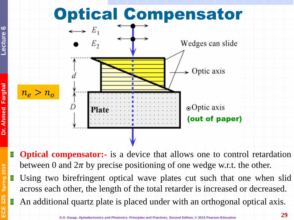
Optical Compensator
29
Optical compensator:- is a device that allows one to control retardation
between 0 and 2𝜋 by precise positioning of one wedge w.r.t. the other.
Using two birefringent optical wave plates cut such that one when slid
across each other, the length of the total retarder is increased or decreased.
An additional quartz plate is placed under with an orthogonal optical axis.
𝑛𝑒 > 𝑛𝑜
(out of paper)
S.O. Kasap, Optoelectronics and Photonics: Principles and Practices, Second Edition, © 2013 Pearson Education
Variable waveplate
EC
E 3
25
S
pri
ng
20
19
D
r. A
hm
ed
F
arg
ha
l L
ec
ture
6
Optical Compensator
30
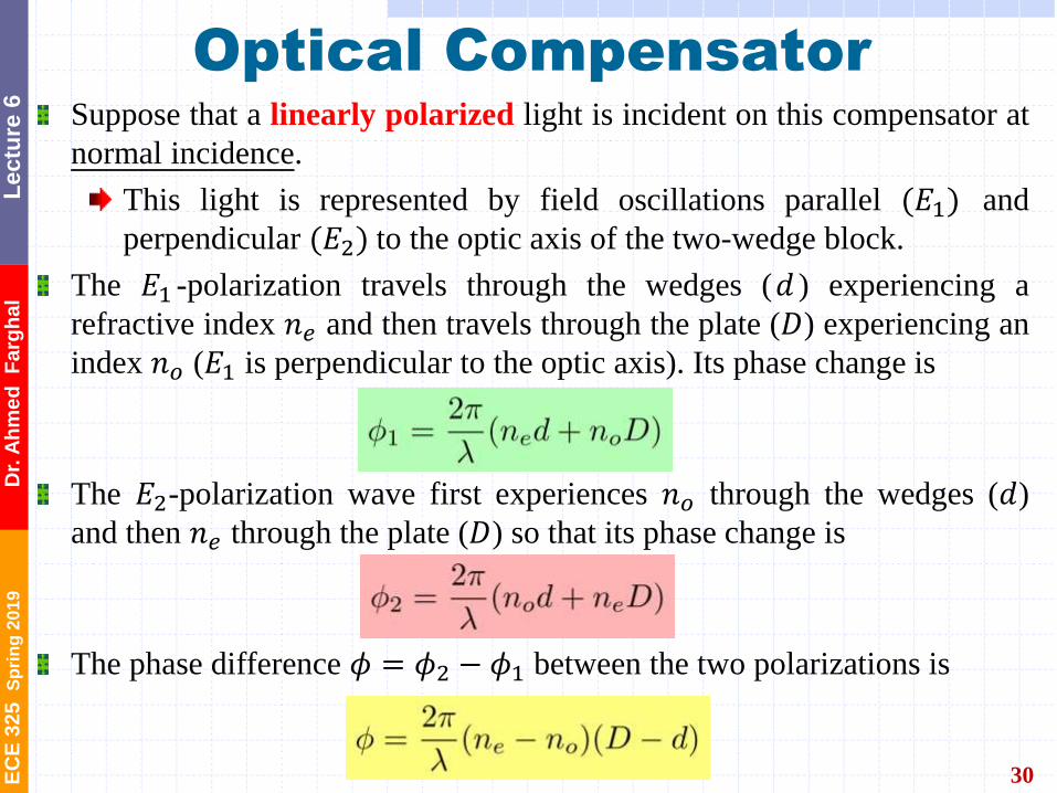
Suppose that a linearly polarized light is incident on this compensator at
normal incidence.
This light is represented by field oscillations parallel (𝐸1) and
perpendicular (𝐸2) to the optic axis of the two-wedge block.
The 𝐸1 -polarization travels through the wedges (𝑑 ) experiencing a
refractive index 𝑛𝑒 and then travels through the plate (𝐷) experiencing an
index 𝑛𝑜 (𝐸1 is perpendicular to the optic axis). Its phase change is
The 𝐸2-polarization wave first experiences 𝑛𝑜 through the wedges (𝑑)
and then 𝑛𝑒 through the plate (𝐷) so that its phase change is
The phase difference 𝜙 = 𝜙2 − 𝜙1 between the two polarizations is ))((
2dDnn oe --

EC
E 3
25
S
pri
ng
20
19
D
r. A
hm
ed
F
arg
ha
l L
ec
ture
6
Soleil-Babinet Compensator
31
Courtesy of Thorlabs https://www.thorlabs.com/newgrouppage9.cfm?objectgroup_id=871
Compensator:
―A device that allows a continuous adjustment of the relative phase shift, the retardance.
Soleil-Babinet compensator. (Left) Zero retardation. (Right) Maximum retardation.

EC
E 3
25
S
pri
ng
20
19
D
r. A
hm
ed
F
arg
ha
l L
ec
ture
6
32
Thank you