Polarisation response of mono-order concave diffraction gratings based on an elliptical Bragg...
9
This article was downloaded by: [Moskow State Univ Bibliote] On: 09 September 2013, At: 11:46 Publisher: Taylor & Francis Informa Ltd Registered in England and Wales Registered Number: 1072954 Registered office: Mortimer House, 37-41 Mortimer Street, London W1T 3JH, UK Journal of Modern Optics Publication details, including instructions for authors and subscription information: http://www.tandfonline.com/loi/tmop20 Polarisation response of mono-order concave diffraction gratings based on an elliptical Bragg reflector Pierre Pottier a & Muthukumaran Packirisamy a a Optical-Bio Microsystems Laboratory, Department of Mechanical & Industrial Engineering , Concordia University , 1455 De Maisonneuve Blvd., West, Montreal, QC, H3G 1M8 , Canada Published online: 04 Jul 2013. To cite this article: Pierre Pottier & Muthukumaran Packirisamy (2013) Polarisation response of mono-order concave diffraction gratings based on an elliptical Bragg reflector, Journal of Modern Optics, 60:9, 741-748, DOI: 10.1080/09500340.2013.808384 To link to this article: http://dx.doi.org/10.1080/09500340.2013.808384 PLEASE SCROLL DOWN FOR ARTICLE Taylor & Francis makes every effort to ensure the accuracy of all the information (the “Content”) contained in the publications on our platform. However, Taylor & Francis, our agents, and our licensors make no representations or warranties whatsoever as to the accuracy, completeness, or suitability for any purpose of the Content. Any opinions and views expressed in this publication are the opinions and views of the authors, and are not the views of or endorsed by Taylor & Francis. The accuracy of the Content should not be relied upon and should be independently verified with primary sources of information. Taylor and Francis shall not be liable for any losses, actions, claims, proceedings, demands, costs, expenses, damages, and other liabilities whatsoever or howsoever caused arising directly or indirectly in connection with, in relation to or arising out of the use of the Content. This article may be used for research, teaching, and private study purposes. Any substantial or systematic reproduction, redistribution, reselling, loan, sub-licensing, systematic supply, or distribution in any form to anyone is expressly forbidden. Terms & Conditions of access and use can be found at http:// www.tandfonline.com/page/terms-and-conditions
-
Upload
muthukumaran -
Category
Documents
-
view
213 -
download
0
Transcript of Polarisation response of mono-order concave diffraction gratings based on an elliptical Bragg...

This article was downloaded by: [Moskow State Univ Bibliote]On: 09 September 2013, At: 11:46Publisher: Taylor & FrancisInforma Ltd Registered in England and Wales Registered Number: 1072954 Registered office: Mortimer House,37-41 Mortimer Street, London W1T 3JH, UK
Journal of Modern OpticsPublication details, including instructions for authors and subscription information:http://www.tandfonline.com/loi/tmop20
Polarisation response of mono-order concavediffraction gratings based on an elliptical BraggreflectorPierre Pottier a & Muthukumaran Packirisamy aa Optical-Bio Microsystems Laboratory, Department of Mechanical & Industrial Engineering ,Concordia University , 1455 De Maisonneuve Blvd., West, Montreal, QC, H3G 1M8 , CanadaPublished online: 04 Jul 2013.
To cite this article: Pierre Pottier & Muthukumaran Packirisamy (2013) Polarisation response of mono-orderconcave diffraction gratings based on an elliptical Bragg reflector, Journal of Modern Optics, 60:9, 741-748, DOI:10.1080/09500340.2013.808384
To link to this article: http://dx.doi.org/10.1080/09500340.2013.808384
PLEASE SCROLL DOWN FOR ARTICLE
Taylor & Francis makes every effort to ensure the accuracy of all the information (the “Content”) containedin the publications on our platform. However, Taylor & Francis, our agents, and our licensors make norepresentations or warranties whatsoever as to the accuracy, completeness, or suitability for any purpose of theContent. Any opinions and views expressed in this publication are the opinions and views of the authors, andare not the views of or endorsed by Taylor & Francis. The accuracy of the Content should not be relied upon andshould be independently verified with primary sources of information. Taylor and Francis shall not be liable forany losses, actions, claims, proceedings, demands, costs, expenses, damages, and other liabilities whatsoeveror howsoever caused arising directly or indirectly in connection with, in relation to or arising out of the use ofthe Content.
This article may be used for research, teaching, and private study purposes. Any substantial or systematicreproduction, redistribution, reselling, loan, sub-licensing, systematic supply, or distribution in anyform to anyone is expressly forbidden. Terms & Conditions of access and use can be found at http://www.tandfonline.com/page/terms-and-conditions
Polarisation response of mono-order concave diffraction gratings based on an elliptical Braggreflector
Pierre Pottier* and Muthukumaran Packirisamy
Optical-Bio Microsystems Laboratory, Department of Mechanical & Industrial Engineering, Concordia University,1455 De Maisonneuve Blvd. West, Montreal, QC, H3G 1M8, Canada
(Received 30 January 2013; final version received 12 May 2013)
The polarisation dependence of integrated concave diffraction gratings with extended metallic or dielectric elliptical Braggreflectors was investigated. Equal grating efficiency of 99% for both polarisations was achieved for the dielectricconfiguration using finite-difference time-domain (FDTD) modelling, with a polarisation-dependent loss (PDL) of 0.07dB.
Keywords: optical fibres and optical communications; diffraction grating; Bragg reflector; polarisation dependency; inte-grated planar spectrometer; wavelength division multiplexing; optical design
1. Introduction
The large demand for the development of opticaltelecommunications using optical fibres has led to theuse of the wavelength division multiplexing (WDM)technique, which has enabled multiplication of networkcapacity. Initially developed to increase voice traffic, thistechnique also made possible the development of aninternet with high capacity for data transmission. In anever growing market, more demand is expected with theuse of notably video including high definition/ultra-highdefinition television (HDTV/UHDTV), along with thedevelopment of fibre-to-the-home (FTTH) products. Inorder to provide a solution with a reasonable cost, moreefficient WDM components with an ability to handlemore capacity need to be developed, such as reconfigura-ble optical add–drop multiplexers (ROADMs). In addi-tion, reducing the losses in components would allowminimisation of the number of repeaters needed forlong-haul transmission by increasing the distancerequired between repeating units. Presently, thecommonly deployed multi/demultiplexers are based onintegrated optics, notably the arrayed waveguide grating(AWG) [1,2]. A counterpart to the AWG is the concavediffraction grating (CDG) [2–8]. CDGs present some dif-ficulties in fabrication to obtain vertical walls for thegrating which, if not adequate, will translate into losses.The metallization of the grating will also absorb somelight, in the order of 0.5 dB [8]. But CDGs presentadvantages when handling a high number of channels.They can be much smaller in size. Firstly, they are
folded compared to AWGs because they work inreflection mode. Secondly, the size occupied by the arrayof waveguides in AWGs, which is already occupying asignificant area of the device, would increase dramati-cally during scaling, making them impractical. AWGsalso suffer from losses and phase errors due to fabrica-tion tolerances and mismatch at the connection betweenthe input waveguide and the array of waveguides,leading to crosstalk. AWG losses in commercially avail-able devices are of the order of 3 dB (for Gaussian type)[9–11]. Microspectrometers can also be built on AWGsand CDGs, e.g. for the detection of elements (gas,biomolecules) and possibly integrated monolithicallywith other devices [12], including astronomical applica-tions [13].
AWGs and CDGs are polarisation-dependent devices.One reason is that the slab waveguide, which is the mainelement of these devices, has a different effective indexfor transverse electric (TE) and transverse magnetic(TM) modes. In addition, stress can be present in thedeposited layers, leading to an induced birefringence. InCDGs, the boundary conditions at the metal facets playan important role in determining polarisation depen-dence. For the side facets (i.e. the edges of reflectingfacets), these conditions are different for TE and TMmodes [2], which leads to a different power efficiencyfor a given diffracted order. To compensate for this, it ispossible to equalise to the lower of the two polarisations,but this adds losses. One can also apply compensation
*Corresponding author. Email: [email protected]
Journal of Modern Optics, 2013Vol. 60, No. 9, 741–748, http://dx.doi.org/10.1080/09500340.2013.808384
� 2013 Taylor & Francis
Dow
nloa
ded
by [
Mos
kow
Sta
te U
niv
Bib
liote
] at
11:
46 0
9 Se
ptem
ber
2013

techniques, such as modifying the grating profile [14] orinserting a compensating section by etching a part of theslab waveguide region [7,15]. But these extra steps alsolead to additional losses. Here it is proposed to obtainlow polarisation dependence for the grating withoutusing any compensation techniques, but by working onthe grating design part. By using elliptical Braggreflectors extended all over and generating the diffractiongrating, it will be shown through simulations that highefficiency can be obtained for the two polarisations, withlow polarisation dependence. These new results are ofimportance as the effect of polarisation on loss andwavelength is critical for real applications such as WDMand spectrometry. They demonstrate enhancement interms of performance while at the same time making asmall device size and single fabrication step possible.
2. Grating configurations
The diffraction gratings considered here are concaveand are based on the Rowland configuration [2,3]. Thatis to say, the input light emanates from a waveguidepositioned on a circle of radius RRC (the Rowland cir-cle) and the diffracted light from the grating will focuson output waveguides, placed on the same circle (Fig-ure 1). For this, a grating curved with radius 2RRC andtangent to the Rowland circle is used. The whole struc-ture is planar, with a slab area of effective index nbetween the waveguides and the grating. Four differentdesign cases are considered in order to demonstrate therelative performance. The first (case 1) consists of aclassical diffraction grating made of dielectric material(index n2), as shown in Figure 1(a). The second (case2) is a classical diffraction grating but now made ofmetal (Figure 1(b)). The third (case 3) consists of a dif-fraction grating made of thin lines of metal, placed onconfocal ellipses whose foci are at the input and centraloutput waveguides (Figure 1(c)), as described in [16].The elliptical metal lines start at the grating circle andextend in depth, and the diffraction grating period iskept the same as for the previous cases. The fourth sit-uation (case 4) is a diffraction grating made of dielec-tric stripes arranged elliptically, in a similar way ascase 3, but now with an alternation of dielectric materi-als of indices n2 and n (Figure 1(d )), as described in[17]. They thus form an elliptical distributed Braggreflector (DBR). Cases 1 to 4 present facets which areblazed, and cases 3 and 4 have the particularity to alsocombine diffraction grating with Bragg conditions andprovide an aberration-free focusing.
3. Simulation results
Two-dimensional (2D) finite-difference time-domain(FDTD) simulations were performed to monitor the
power distribution of light for the four differentconfigurations. The refractive indices used are n = 1.5for the slab area and n2 = 1 for the dielectric materialused in the diffraction grating, which correspond, respec-tively, to a SiO2-style waveguide and air, and the metalused is aluminium. The base wavelength of light invacuum is λ = 600 nm, the incidence angle on the grat-ing is α = �15°, the refracted angle is β = �45°, thegrating order is M = �2 and the Rowland circle radius isRRC = 50 μm. From the diffraction grating condition,
Mk ¼ naðsin aþ sinbÞ; ð1Þ
the grating period is obtained as a = 828 nm. The incli-nation angle of the facets or the stripes with respect tothe grating surface (blaze condition) is
h ¼ �a� b2
; ð2Þ
i.e. h = 30°. For cases 3 and 4, the Bragg condition isgiven by [17]
mk ¼ 2 nd1 cosa� b2
� �þ n2d2
ffiffiffiffiffiffiffiffiffiffiffiffiffiffiffiffiffiffiffiffiffiffiffiffiffiffiffiffiffiffiffiffiffiffiffiffiffiffiffiffiffiffiffiffiffiffiffiffi1� n
n2
� �2
sin2a� b2
� �s24
35;ð3Þ
with m the Bragg order, d2 the width of lines or stripesand d1 the spacing between stripes. Within the approxi-mation of thin lines or stripes (d2 << d1), m = �M andthe Bragg period is
d ¼ a sin h; ð4Þ
with d = d1 + d2, which gives d = 414 nm. All theseparameters are the same as those used in [16] and [17],so that comparison of polarisation can be established. TEand TM refer, respectively, to light polarised within andperpendicular to the plane of simulation (i.e. the slabwaveguide plane). Note that the results obtained herecan be translated to any wavelength, in particular 1.5 μm(as long as the indices are kept the same).
For case 1, i.e. a classical diffraction grating with aSiO2–air interface (Figure 2), the TM efficiency for thedesigned outputs is quite low (Figure 3). As can be seenin Figure 2, light is diffracted into several diffractionorders, but most of it is transmitted through the gratingbecause the reflectivity of the facets is weak. Thesituation was the same for TE polarisation [17]. But therelative values of efficiency are different, which leads toan important polarisation-dependent loss (PDL) of 7.7 dBover the whole spectrum considered (as shown inFigure 4(a) and Table 1). The PDL presented in this
742 P. Pottier and M. Packirisamy
Dow
nloa
ded
by [
Mos
kow
Sta
te U
niv
Bib
liote
] at
11:
46 0
9 Se
ptem
ber
2013

paper refers to maximum difference observed over allthe considered channels.
When this same grating gets metallised, i.e. for case2 (Figure 5), the TM efficiency increases significantly to57% in the vicinity of λ = 600 nm (Figure 6). The grat-ing reflects most of light, although absorbing a fractionof it, but redirects it into several diffraction orders(Figure 5), making the designed output moderately effi-cient. Again, the situation was similar for TE polarisation[16]. But the different channels do not receive thesame amount of power for the two polarisations. Thedifference is still significant, with a PDL of 3.6 dB(Figure 7(a) and Table 1). As explained in [2], the polar-isation has a different effect on the side facets and thisresults in important variations of power in a given outputchannel.
For case 3, a different grating design is used. Insteadof operating the reflection at the surface of the grating, itis now distributed over a quantity of partial reflectors(thin metallic lines of 10 nm) using elliptical Bragg con-figuration, and therefore takes place more in depth of thegrating (Figure 8). A notable gain in TM efficiency isnoted, from 57% to 82% around the central wavelengthof 600 nm (Figure 9). As for TE [16], no other diffrac-tion orders are visible (Figure 8). For the two polarisa-tions, the spectra now look more similar, with a peak ofhigher efficiency close to the central wavelength forwhich the grating has been designed for. This is reflectedin the PDL value, which has dropped to 1.16 dB for thewhole spectrum (i.e. all the channels 1 to 13), or 0.80 dBfor the specific group of channels 4–6 of higher effi-ciency close to the base wavelength (Figure 10(a) and
Figure 1. Schematic of the four configurations of concave diffraction gratings analysed: (a) dielectric classical diffraction grating(case 1); (b) metallic classical diffraction grating (case 2); (c) elliptical metal thin lines diffraction grating (case 3); and (d ) ellipticaldielectric stripes (DBR) diffraction grating (case 4). (The colour version of this figure is included in the online version of thejournal.)
Journal of Modern Optics 743
Dow
nloa
ded
by [
Mos
kow
Sta
te U
niv
Bib
liote
] at
11:
46 0
9 Se
ptem
ber
2013
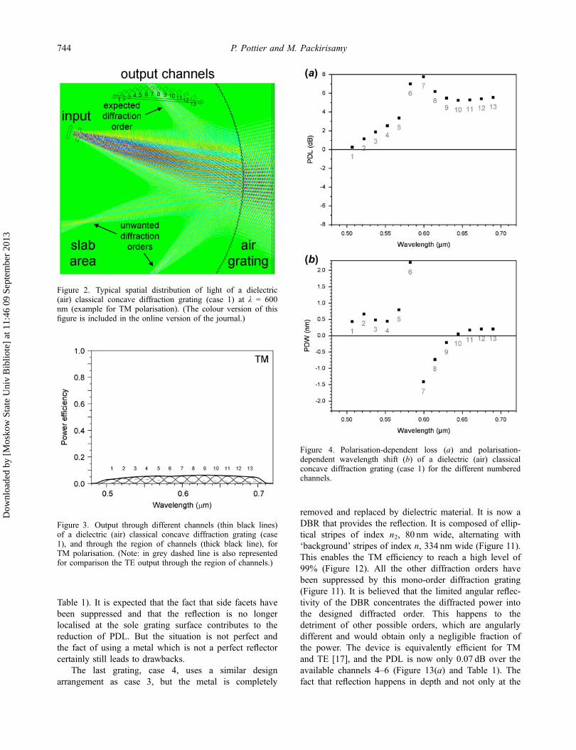
Table 1). It is expected that the fact that side facets havebeen suppressed and that the reflection is no longerlocalised at the sole grating surface contributes to thereduction of PDL. But the situation is not perfect andthe fact of using a metal which is not a perfect reflectorcertainly still leads to drawbacks.
The last grating, case 4, uses a similar designarrangement as case 3, but the metal is completely
removed and replaced by dielectric material. It is now aDBR that provides the reflection. It is composed of ellip-tical stripes of index n2, 80 nm wide, alternating with‘background’ stripes of index n, 334 nm wide (Figure 11).This enables the TM efficiency to reach a high level of99% (Figure 12). All the other diffraction orders havebeen suppressed by this mono-order diffraction grating(Figure 11). It is believed that the limited angular reflec-tivity of the DBR concentrates the diffracted power intothe designed diffracted order. This happens to thedetriment of other possible orders, which are angularlydifferent and would obtain only a negligible fraction ofthe power. The device is equivalently efficient for TMand TE [17], and the PDL is now only 0.07 dB over theavailable channels 4–6 (Figure 13(a) and Table 1). Thefact that reflection happens in depth and not only at the
Figure 3. Output through different channels (thin black lines)of a dielectric (air) classical concave diffraction grating (case1), and through the region of channels (thick black line), forTM polarisation. (Note: in grey dashed line is also representedfor comparison the TE output through the region of channels.)
Figure 2. Typical spatial distribution of light of a dielectric(air) classical concave diffraction grating (case 1) at λ = 600nm (example for TM polarisation). (The colour version of thisfigure is included in the online version of the journal.)
Figure 4. Polarisation-dependent loss (a) and polarisation-dependent wavelength shift (b) of a dielectric (air) classicalconcave diffraction grating (case 1) for the different numberedchannels.
744 P. Pottier and M. Packirisamy
Dow
nloa
ded
by [
Mos
kow
Sta
te U
niv
Bib
liote
] at
11:
46 0
9 Se
ptem
ber
2013

surface of the DBR practically eliminates the role of sidefacets and all the re-emissions are directed into one angledue to the DBR, for both polarisations. Hence, PDL ismostly eliminated, which constitutes another advantageof this grating. The usable bandwidth of this grating islimited because of the limited bandwidth of the DBRbeing used. Nevertheless, translated into telecommunica-tion wavelengths (at 1.55 μm) this corresponds to a110 nm wide band. Furthermore, the efficiency of theDBR can virtually reach 100%.
Let us now point out the possible origins of the tinyloss and their implication on polarisation. Small imper-fections in the facet positions and the difficulty to matchthe diffraction grating with the DBR, as discussed in[17], create small aberrations that can account for the1% of light lost. But these imperfections can beimproved. Also, farther away from the central wave-length, the grating and the DBR start to be a bit lessmatched together, and the efficiency decreases slightly.Concerning the side facets, the residual effect should betiny since the width of the stripes of index n2 is narrow.It should be almost non-existent when the stripes becomevery narrow or when the index contrast n2/n is very low.This would be the case for diffraction gratings made ofalternating SiO2 stripes with close indices, such as on sil-ica-on-silicon (SoS) with an index difference ratio ofaround 1%. An apodisation could also be applied if nec-essary with a progressive change of index at the start ofa stripe at the grating front, reducing even more anyexistence of side facets. Consequently, when operatingclose to perfect conditions, i.e. small beam divergencecompared to Rowland circle radius and narrowbandDBR with small index contrast, the efficiency of thediffraction grating should tend to 100% for bothpolarisations. Then there is no place left for a depen-dence on polarisation, and the PDL should tend to beclose to zero. The limited PDL present in case 4 mostprobably originates from the above-mentioned minordeviations from perfect conditions and could still be low-ered. Concerning possible losses in the third direction,they have been estimated to be very low [17] due to thefact that the stripes of index n2 are relatively narrow.This would also be the case with low index contraststripes.
Table 1. Polarisation-dependent loss (PDL) and polarisation-dependent wavelength shift (PDW) of the four grating configurations.
Case 1 2 3 4
Channels 1–13 4–6 1–13 4–6 1–13 4–6 1–13 4–6
PDL (dB) 7.7 7.0 3.6 3.5 1.16 0.80 n/a 0.07PDW (nm) 2.24 2.24 0.54 0.49 0.49 0.05 n/a 0.06
Figure 5. Typical spatial distribution of light of a metallicclassical concave diffraction grating (case 2) at λ = 600 nm(example for TM polarisation). (The colour version of thisfigure is included in the online version of the journal.)
Figure 6. Output through different channels (thin black lines)of a metallic classical concave diffraction grating (case 2), andthrough the region of channels (thick black line), for TMpolarisation. (Note: in grey dashed line is also represented forcomparison the TE output through the region of channels.)
Journal of Modern Optics 745
Dow
nloa
ded
by [
Mos
kow
Sta
te U
niv
Bib
liote
] at
11:
46 0
9 Se
ptem
ber
2013
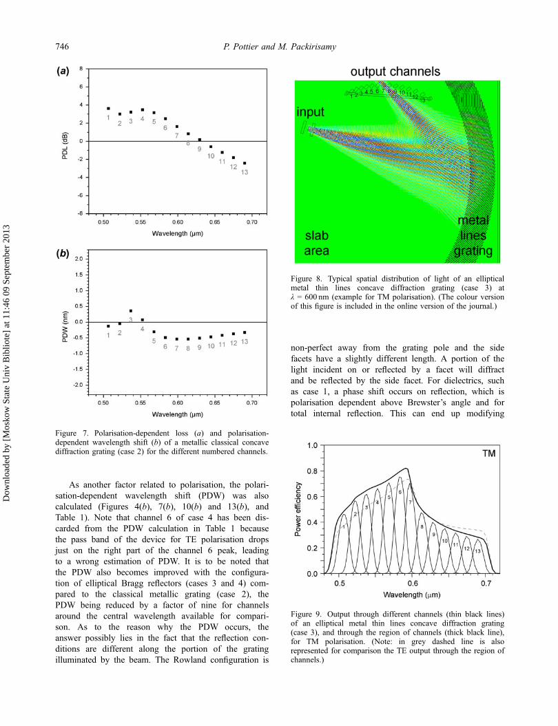
As another factor related to polarisation, the polari-sation-dependent wavelength shift (PDW) was alsocalculated (Figures 4(b), 7(b), 10(b) and 13(b), andTable 1). Note that channel 6 of case 4 has been dis-carded from the PDW calculation in Table 1 becausethe pass band of the device for TE polarisation dropsjust on the right part of the channel 6 peak, leadingto a wrong estimation of PDW. It is to be noted thatthe PDW also becomes improved with the configura-tion of elliptical Bragg reflectors (cases 3 and 4) com-pared to the classical metallic grating (case 2), thePDW being reduced by a factor of nine for channelsaround the central wavelength available for compari-son. As to the reason why the PDW occurs, theanswer possibly lies in the fact that the reflection con-ditions are different along the portion of the gratingilluminated by the beam. The Rowland configuration is
non-perfect away from the grating pole and the sidefacets have a slightly different length. A portion of thelight incident on or reflected by a facet will diffractand be reflected by the side facet. For dielectrics, suchas case 1, a phase shift occurs on reflection, which ispolarisation dependent above Brewster’s angle and fortotal internal reflection. This can end up modifying
Figure 8. Typical spatial distribution of light of an ellipticalmetal thin lines concave diffraction grating (case 3) atλ = 600 nm (example for TM polarisation). (The colour versionof this figure is included in the online version of the journal.)
Figure 7. Polarisation-dependent loss (a) and polarisation-dependent wavelength shift (b) of a metallic classical concavediffraction grating (case 2) for the different numbered channels.
Figure 9. Output through different channels (thin black lines)of an elliptical metal thin lines concave diffraction grating(case 3), and through the region of channels (thick black line),for TM polarisation. (Note: in grey dashed line is alsorepresented for comparison the TE output through the region ofchannels.)
746 P. Pottier and M. Packirisamy
Dow
nloa
ded
by [
Mos
kow
Sta
te U
niv
Bib
liote
] at
11:
46 0
9 Se
ptem
ber
2013
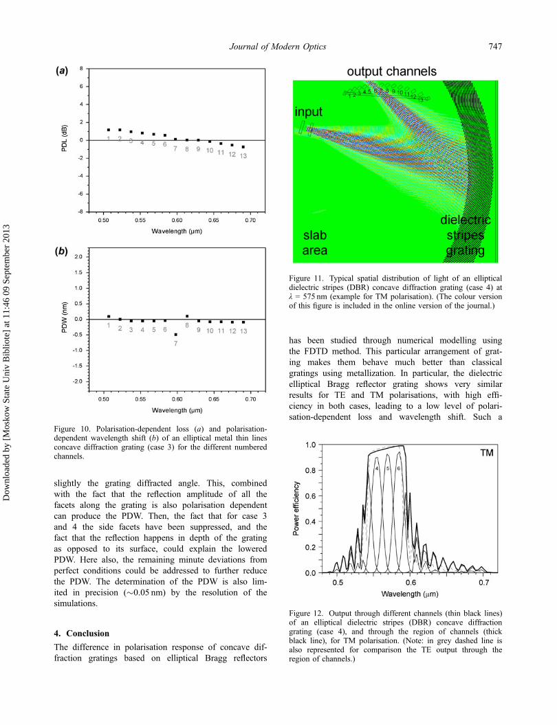
slightly the grating diffracted angle. This, combinedwith the fact that the reflection amplitude of all thefacets along the grating is also polarisation dependentcan produce the PDW. Then, the fact that for case 3and 4 the side facets have been suppressed, and thefact that the reflection happens in depth of the gratingas opposed to its surface, could explain the loweredPDW. Here also, the remaining minute deviations fromperfect conditions could be addressed to further reducethe PDW. The determination of the PDW is also lim-ited in precision (�0.05 nm) by the resolution of thesimulations.
4. Conclusion
The difference in polarisation response of concave dif-fraction gratings based on elliptical Bragg reflectors
has been studied through numerical modelling usingthe FDTD method. This particular arrangement of grat-ing makes them behave much better than classicalgratings using metallization. In particular, the dielectricelliptical Bragg reflector grating shows very similarresults for TE and TM polarisations, with high effi-ciency in both cases, leading to a low level of polari-sation-dependent loss and wavelength shift. Such a
Figure 12. Output through different channels (thin black lines)of an elliptical dielectric stripes (DBR) concave diffractiongrating (case 4), and through the region of channels (thickblack line), for TM polarisation. (Note: in grey dashed line isalso represented for comparison the TE output through theregion of channels.)
Figure 11. Typical spatial distribution of light of an ellipticaldielectric stripes (DBR) concave diffraction grating (case 4) atλ = 575 nm (example for TM polarisation). (The colour versionof this figure is included in the online version of the journal.)
Figure 10. Polarisation-dependent loss (a) and polarisation-dependent wavelength shift (b) of an elliptical metal thin linesconcave diffraction grating (case 3) for the different numberedchannels.
Journal of Modern Optics 747
Dow
nloa
ded
by [
Mos
kow
Sta
te U
niv
Bib
liote
] at
11:
46 0
9 Se
ptem
ber
2013

grating design would bring advantages in WDM byenabling smaller devices, increasing efficiency andallowing more capacity.
AcknowledgementsThe authors would like to acknowledge financial support fromthe Ministère du Développement Economique, de l’Innovation
et de l’Exportation of Quebec (MDEIE) and the NaturalSciences and Engineering Research Council of Canada(NSERC).
References[1] Smit, M.K. Electron. Lett. 1988, 24, 385–386.[2] Cheben, P. In Optical Waveguides: From Theory to
Applied Technologies; Calvo, M.L., Lakshminarayanan,V., Eds.; CRC Press: Boca Raton, FL, 2007; Chapter 5.
[3] Hutley, M.C. Diffraction Gratings (Techniques of Physics6); Academic Press: London, 1982.
[4] Soole, J.B.D.; Scherer, A.; LeBlanc, H.P.; Andreadakis,N.C.; Bhat, R.; Koza, M.A. Appl. Phys. Lett. 1991, 58,1949–1951.
[5] Cremer, C.; Ebbinghaus, G.; Heise, G.; Müller-Nawrath,R.; Schienle, M.; Stoll, L. Appl. Phys. Lett. 1991, 59,627–629.
[6] Clemens, P.C.; März, R.; Reichelt, A.; Schneider, H.W.IEEE Photonics Technol. Lett. 1992, 4, 886–887.
[7] Janz, S.; Balakrishnan, A.; Charbonneau, S.; Cheben, P.;Cloutier, M.; Delâge, A.; Dossou, K.; Erickson, L.; Gao,M.; Krug, P.A.; Lamontagne, B.; Packirisamy, M.; Pear-son, M.; Xu, D.-X. IEEE Photonics Technol. Lett. 2004,16, 503–505.
[8] Bidnyk, S.; Balakrishnan, A.; Delâge, A.; Gao, M.; Krug,P.A.; Muthukumaran, P.; Pearson, M. J. Lightwave Tech-nol. 2005, 23, 1435–1440.
[9] JDSU Home Page. 100 GHz, narrowband (Gaussian)arrayed waveguide grating (AWG), 2009. http://www.jdsu.com/ProductLiterature/awg100n_ds_cc_ae.pdf (accessedOct 25, 2012).
[10] NTT Electronics Home Page. AWG multi/demultiplexer.http://www.ntt-electronics.com/en/products/photonics/awg_mul_d.html (accessed Oct 25, 2012).
[11] Enablence. 100 GHz wavelength division multiplexer/demultiplexer, 2010. http://www.enablence.com/media/mediamanager/pdf/18-enablence-datasheet-ocsd-awg-stan-dard-100ghzmultidemulti.pdf (accessed Oct 25, 2012).
[12] Kodate, K.; Komai, Y. J. Opt. A: Pure Appl. Opt. 2008,10, 044011.
[13] Cvetojevic, N.; Jovanovic, N.; Lawrence, J.; Withford, M.;Bland-Hawthorn, J. Opt. Express 2012, 20, 2062–2072.
[14] Chowdhury, D. IEEE J. Sel. Top. Quantum Electron.2000, 6, 233–239.
[15] He, J.-J.; Koteles, E.S.; Lamontagne, B.; Erickson, L.;Delâge, A.; Davies, M. IEEE Photonics Technol. Lett.1999, 11, 224–226.
[16] Pottier, P.; Packirisamy, M. Appl. Opt. 2012, 51,4073–4077.
[17] Pottier, P.; Packirisamy, M. J. Lightwave Technol. 2012,30, 2922–2928.
Figure 13. Polarisation-dependent loss (a) and polarisation-dependent wavelength shift (b) of an elliptical dielectric stripes(DBR) concave diffraction grating (case 4) for the differentnumbered channels.
748 P. Pottier and M. Packirisamy
Dow
nloa
ded
by [
Mos
kow
Sta
te U
niv
Bib
liote
] at
11:
46 0
9 Se
ptem
ber
2013
![AB CD-matrix for holographic gratings · Exam ples of application of Gaussian beams are given in [6, 7, 9,13]. For the incorporation of concave gratings in optical systems a first](https://static.fdocuments.in/doc/165x107/60daf4464c24ed44c43f8792/ab-cd-matrix-for-holographic-gratings-exam-ples-of-application-of-gaussian-beams.jpg)