Polaris Owner’s Manual - Wilson Audio · Polaris Owner’s Manual Wilson Audio® is a registered...
105
Polaris Owner’s Manual
Transcript of Polaris Owner’s Manual - Wilson Audio · Polaris Owner’s Manual Wilson Audio® is a registered...

P o l a r i s O w n e r ’ s M a n u a l

Polaris Owner’s ManualW i l s o n A u d i o ® i s a r e g i s t e re d t r a d e m a r k o f W i l s o n A u d i o S p e c i a l t i e s , I n c .
S o p h i a ® , S a s h a , W i l s o n A u d i o D u e t t e , WAT T / P u p p y ® , M A X X , X - 1 G r a n d S L A M M ® , P o l a r i s ® a n d A l e x a n d r i a ® a re r e g i s t e re d t r a d e m a r k s o f W i l s o n A u d i o S p e c i a l t i e s , I n c .
W i l s o n G l o s s ™ , WAT C H ® C e n t e r, WAT C H ® S u r ro u n d , a n d WAT C H ® D o g a re t r a d e -m a r k s o f W i l s o n A u d i o S p e c i a l t i e s , I n c . T h e W i l s o n A u d i o D u e t t e i s a l s o a p ro d u c t o f W i l s o n A u d i o S p e c i a l t i e s , I n c .
T h i s m a n u a l w a s p ro d u c e d b y t h e W i l s o n A u d i o E n g i n e e r i n g a n d t h e S a l e s a n d M a r-k e t i n g D e p a r t m e n t s . T h e i n f o r m a t i o n c o n t a i n e d h e re i n i s s u b j e c t t o c h a n g e w i t h o u t n o t i c e . C u r re n t R e v i s i o n 3 . 0 . I f y o u a re i n n e e d o f a m o re r e c e n t m a n u a l , p l e a s e c o n t a c t y o u r d e a l e r.
T h e i n f o r m a t i o n i n t h i s m a n u a l i s t h e s o l e p ro p e r t y o f W i l s o n A u d i o S p e c i a l t i e s , I n c . A n y r e p ro d u c t i o n , i n w h o l e o r i n p a r t , w i t h o u t t h e e x p re s s w r i t t e n p e r m i s s i o n o f W i l s o n A u d i o S p e c i a l t i e s , I n c . , i s p ro h i b i t e d . N o m a t e r i a l c o n t a i n e d h e re i n m a y b e t r a n s m i t t e d i n a n y f o r m o r b y a n y m e a n s , e l e c t ro n i c o r m e c h a n i c a l , f o r a n y p u r p o s e , w i t h o u t t h e e x p re s s w r i t t e n p e r m i s s i o n o f W i l s o n A u d i o S p e c i a l t i e s , I n c .
P o l a r i s o w n e r ’ s M a n u a l
2W i l s o n A u d i o S p e c i a l t i e s

3
Contents
P o l a r i s o w n e r ’ s M a n u a l � � � � � � � � � � � � � � � � � � � � � � � � � � � � � � � � � � � � � � � � � � � � � 1
s e c t i o n 1 � 1 – i n t r o d u c t i o n � � � � � � � � � � � � � � � � � � � � � � � � � � � � � � � � � � � � � � � � � � 9
M o r e o n A s p h e r i c A l p r o p A g A t i o n d e l A y � � � � � � � � � � � � � � � � � � � � � � � 1 3
s e c t i o n 2 � 1 – u n c r a t i n g t h e P o l a r i s � � � � � � � � � � � � � � � � � � � � � � � � � � � � 1 7
i n i t i A l c h e c k � � � � � � � � � � � � � � � � � � � � � � � � � � � � � � � � � � � � � � � � � � � � � � � � � � � � � � 1 7
U n c r A t i n g t h e p o l A r i s � � � � � � � � � � � � � � � � � � � � � � � � � � � � � � � � � � � � � � � � � � � 1 7
s e c t i o n 2 � 2 – c r a t e c o n t e n t c h e c k l i s t � � � � � � � � � � � � � � � � � � � � � � � � � 1 7
p o l A r i s c r A t e � � � � � � � � � � � � � � � � � � � � � � � � � � � � � � � � � � � � � � � � � � � � � � � � � � � � � 1 8
s e c t i o n 3 � 1 – t h e w i l s o n a u d i o s e t u P P r o c e d u r e � � � � � � � � � � � � 2 3
F i n A l l i s t e n i n g r o o M s e t U p ( V o i c i n g ) � � � � � � � � � � � � � � � � � � � � � � � � � 2 3
Z o n e o F n e U t r A l i t y : M A i n l e F t A n d r i g h t c h A n n e l � � � � � � � � � 2 3
s e c t i o n 3 � 2 – r o o M a c o u s t i c s � � � � � � � � � � � � � � � � � � � � � � � � � � � � � � � � � � � � � 2 5
s l A p e c h o � � � � � � � � � � � � � � � � � � � � � � � � � � � � � � � � � � � � � � � � � � � � � � � � � � � � � � � � � � 2 5
s t A n d i n g W A V e s � � � � � � � � � � � � � � � � � � � � � � � � � � � � � � � � � � � � � � � � � � � � � � � � � � � 2 8
c o M b F i l t e r e F F e c t � � � � � � � � � � � � � � � � � � � � � � � � � � � � � � � � � � � � � � � � � � � � � � � 2 9
s e c t i o n 3 � 3 – r e s o n a n c e s � � � � � � � � � � � � � � � � � � � � � � � � � � � � � � � � � � � � � � � � � � 2 9
s t r U c t U r A l r e s o n A n c e � � � � � � � � � � � � � � � � � � � � � � � � � � � � � � � � � � � � � � � � � � � 3 0
V o l U M e r e s o n A n c e � � � � � � � � � � � � � � � � � � � � � � � � � � � � � � � � � � � � � � � � � � � � � � � � 3 0
s e c t i o n 3 � 4 – Y o u r r o o M � � � � � � � � � � � � � � � � � � � � � � � � � � � � � � � � � � � � � � � � � � � 3 1
r o o M s h A p e s � � � � � � � � � � � � � � � � � � � � � � � � � � � � � � � � � � � � � � � � � � � � � � � � � � � � � � 3 1
p o l A r i s i n A d e d i c A t e d h o M e t h e A t e r � � � � � � � � � � � � � � � � � � � � � � � � � 3 2
s p e A k e r p l A c e M e n t V e r s U s l i s t e n i n g p o s i t i o n � � � � � � � � � � � � � � 3 3
s p e A k e r o r i e n t A t i o n � � � � � � � � � � � � � � � � � � � � � � � � � � � � � � � � � � � � � � � � � � � � � 3 3
p o l A r i s � � � � � � � � � � � � � � � � � � � � � � � � � � � � � � � � � � � � � � � � � � � � � � � � � � � � � � � � � � � � � 3 4
s e c t i o n 4 � 1 – i n i t i a l a s s e M b l Y � � � � � � � � � � � � � � � � � � � � � � � � � � � � � � � � � � � � 3 7
W i l s o n A u d i o S p e c i a l t i e s
T a b l e o f C o n T e n T s P o l a r i s o w n e r ’ s M a n u a l P o l a r i s o w n e r ’ s M a n u a l
r e M o V i n g t h e p r o t e c t i V e F i l M � � � � � � � � � � � � � � � � � � � � � � � � � � � � � � � � � � 3 7
s e c t i o n 4 � 2 – g e o M e t r i c t i M e d o M a i n a l i g n M e n t � � � � � � � � � � � � � � 3 8
M A t e r i A l s r e q U i r e d � � � � � � � � � � � � � � � � � � � � � � � � � � � � � � � � � � � � � � � � � � � � � � � 3 8
p r o p A g A t i o n d e l A y A l i g n M e n t � � � � � � � � � � � � � � � � � � � � � � � � � � � � � � � � � � � 3 8
r o o M s e t U p � � � � � � � � � � � � � � � � � � � � � � � � � � � � � � � � � � � � � � � � � � � � � � � � � � � � � � � � 3 8
A l i g n M e n t p r o c e d U r e � � � � � � � � � � � � � � � � � � � � � � � � � � � � � � � � � � � � � � � � � � � � 3 9
s e c t i o n 4 � 3 – M o u n t i n g t h e M i d r a n g e M o d u l e � � � � � � � � � � � � � � � � 4 2
M A t e r i A l s r e q U i r e d � � � � � � � � � � � � � � � � � � � � � � � � � � � � � � � � � � � � � � � � � � � � � � � 4 2
i n s t A l l t h e M i d r A n g e M o d U l e � � � � � � � � � � � � � � � � � � � � � � � � � � � � � � � � � � � 4 3
s e c t i o n 4 � 4 – M o u n t i n g t h e t w e e t e r M o d u l e � � � � � � � � � � � � � � � � � � 4 4
s e c t i o n 4 � 5 – c o n n e c t i n g u P P e r M o d u l e s ’ s i g n a l c a b l e � � � � 4 4
s e c t i o n 4 � 6 – s P i k e i n s t a l l a t i o n � � � � � � � � � � � � � � � � � � � � � � � � � � � � � � � � � � 4 5
s p i k e A s s e M b l y � � � � � � � � � � � � � � � � � � � � � � � � � � � � � � � � � � � � � � � � � � � � � � � � � � � � 4 5
s e c t i o n 4 � 7 – u s i n g t h e l i f t t o i n s t a l l s P i k e s � � � � � � � � � � � � � � � � 4 6
M A t e r i A l s r e q U i r e d � � � � � � � � � � � � � � � � � � � � � � � � � � � � � � � � � � � � � � � � � � � � � � � 4 6
i n s t A l l A t i o n p r o c e d U r e � � � � � � � � � � � � � � � � � � � � � � � � � � � � � � � � � � � � � � � � � � 4 7
l e V e l i n g t h e p o l A r i s � � � � � � � � � � � � � � � � � � � � � � � � � � � � � � � � � � � � � � � � � � � � � 4 8
s e c t i o n 4 � 8 – r e s i s t o r s � � � � � � � � � � � � � � � � � � � � � � � � � � � � � � � � � � � � � � � � � � � � 4 9
M i d r A n g e A n d t W e e t e r r e s i s t o r s � � � � � � � � � � � � � � � � � � � � � � � � � � � � � � 5 0
W o o F e r d A M p i n g r e s i s t o r � � � � � � � � � � � � � � � � � � � � � � � � � � � � � � � � � � � � � � � 5 0
s e c t i o n 4 � 9 – b r e a k - i n P e r i o d � � � � � � � � � � � � � � � � � � � � � � � � � � � � � � � � � � � � 5 1
s e c t i o n 5 � 1 – t i P s f o r f i n a l t u n i n g a n d V o i c i n g , t h e a t e r � � � 5 5
s e c t i o n 5 � 2 - l e f t a n d r i g h t c h a n n e l s � � � � � � � � � � � � � � � � � � � � � � � � � 5 6
d e t e r M i n i n g F r o n t t o b A c k d i s t A n c e � � � � � � � � � � � � � � � � � � � � � � � � � 5 6
d e t e r M i n i n g s i d e t o s i d e d i s t A n c e � � � � � � � � � � � � � � � � � � � � � � � � � � � � 5 7
s e c t i o n 5 � 3 - i n t e g r a t i n g t h e P o l a r i s i n t o a t h e a t e r � � � � � � � 5 8
P o l a r i s o w n e r ’ s M a n u a l
4W i l s o n A u d i o S p e c i a l t i e s

i n t e g r A t i n g t h e p o l A r i s A s A c e n t e r c h A n n e l � � � � � � � � � � � � � � � � 5 8
i M A g e h e i g h t � � � � � � � � � � � � � � � � � � � � � � � � � � � � � � � � � � � � � � � � � � � � � � � � � � � � � � � 5 9
c o r r e c t p o l A r i t y � � � � � � � � � � � � � � � � � � � � � � � � � � � � � � � � � � � � � � � � � � � � � � � � � 5 9
i n t e g r A t i n g t h e W A t c h s U r r o U n d c h A n n e l s � � � � � � � � � � � � � � � � 5 9
i n t e g r A t i n g t h e p A s s i V e W A t c h d o g o r t h o r ’ s h A M M e r � � 6 0
s e c t i o n 6 � 1 – c a r e o f t h e f i n i s h � � � � � � � � � � � � � � � � � � � � � � � � � � � � � � � � � 6 3
d U s t i n g t h e p o l A r i s � � � � � � � � � � � � � � � � � � � � � � � � � � � � � � � � � � � � � � � � � � � � � � 6 3
c A r e o F t h e g r i l l s � � � � � � � � � � � � � � � � � � � � � � � � � � � � � � � � � � � � � � � � � � � � � � � 6 3
s e c t i o n 6 � 2 – e n c l o s u r e t e c h n o l o g Y � � � � � � � � � � � � � � � � � � � � � � � � � � � � 6 4
M A t e r i A l s � � � � � � � � � � � � � � � � � � � � � � � � � � � � � � � � � � � � � � � � � � � � � � � � � � � � � � � � � � 6 4
A d h e s i V e � � � � � � � � � � � � � � � � � � � � � � � � � � � � � � � � � � � � � � � � � � � � � � � � � � � � � � � � � � � � 6 5
s e c t i o n 6 � 3 – d e P t h o f d e s i g n � � � � � � � � � � � � � � � � � � � � � � � � � � � � � � � � � � � � 6 5
s e c t i o n 7 � 1 – t r o u b l e s h o o t i n g : � � � � � � � � � � � � � � � � � � � � � � � � � � � � � � � � � � � 6 9
s e c t i o n 8 � 1 - r e P a i r P r o c e d u r e s � � � � � � � � � � � � � � � � � � � � � � � � � � � � � � � � � 7 3
r e p l A c i n g A b l o W n r e s i s t o r � � � � � � � � � � � � � � � � � � � � � � � � � � � � � � � � � � � � 7 3
r e p l A c i n g A d A M A g e d d r i V e r � � � � � � � � � � � � � � � � � � � � � � � � � � � � � � � � � � � � 7 4
s e c t i o n 9 � 1 - P o l a r i s s P e c i f i c a t i o n s � � � � � � � � � � � � � � � � � � � � � � � � � � � � 7 9
e n c l o s U r e t y p e : � � � � � � � � � � � � � � � � � � � � � � � � � � � � � � � � � � � � � � � � � � � � � � � � � � 7 9
d r i V e r s : � � � � � � � � � � � � � � � � � � � � � � � � � � � � � � � � � � � � � � � � � � � � � � � � � � � � � � � � � � � � 7 9
M e A s U r e M e n t s : � � � � � � � � � � � � � � � � � � � � � � � � � � � � � � � � � � � � � � � � � � � � � � � � � � � � 7 9
d i M e n s i o n s : � � � � � � � � � � � � � � � � � � � � � � � � � � � � � � � � � � � � � � � � � � � � � � � � � � � � � � � � 7 9
P o l a r i s d i M e n s i o n s � � � � � � � � � � � � � � � � � � � � � � � � � � � � � � � � � � � � � � � � � � � � � � � � � � � 8 0
P o l a r i s i M P e d a n c e c u r V e � � � � � � � � � � � � � � � � � � � � � � � � � � � � � � � � � � � � � � � � � � � � 8 1
s e c t i o n 1 0 � 1 – P o l a r i s P r o P a g a t i o n d e l a Y t a b l e � � � � � � � � � � � � 8 5
f o o t n o t e s t o a l i g n M e n t t a b l e s � � � � � � � � � � � � � � � � � � � � � � � � � � � � � � � � � � � 8 9
s e c t i o n 1 1 � 1 – w a r r a n t Y i n f o r M a t i o n � � � � � � � � � � � � � � � � � � � � � � � � � � � 9 3
T a b l e o f C o n T e n T s P o l a r i s o w n e r ’ s M a n u a l P o l a r i s o w n e r ’ s M a n u a l
5W i l s o n A u d i o S p e c i a l t i e s

l i M i t e d W A r r A n t y � � � � � � � � � � � � � � � � � � � � � � � � � � � � � � � � � � � � � � � � � � � � � � � � � 9 3
c o n d i t i o n s � � � � � � � � � � � � � � � � � � � � � � � � � � � � � � � � � � � � � � � � � � � � � � � � � � � � � � � � � 9 3
r e M e d y � � � � � � � � � � � � � � � � � � � � � � � � � � � � � � � � � � � � � � � � � � � � � � � � � � � � � � � � � � � � � � 9 4
W A r r A n t y l i M i t e d t o o r i g i n A l p U r c h A s e r � � � � � � � � � � � � � � � � � � � � 9 4
d e M o n s t r A t i o n e q U i p M e n t � � � � � � � � � � � � � � � � � � � � � � � � � � � � � � � � � � � � � � � 9 5
M i s c e l l A n e o U s � � � � � � � � � � � � � � � � � � � � � � � � � � � � � � � � � � � � � � � � � � � � � � � � � � � � � 9 5
P o l a r i s o w n e r ’ s M a n u a l
6W i l s o n A u d i o S p e c i a l t i e s

P o l a r i s o w n e r ’ s M a n u a l
7W i l s o n A u d i o S p e c i a l t i e s

W i l s o n A u d i o S p e c i a l t i e sW i l s o n A u d i o S p e c i a l t i e s
S e c t i o n 1 – I n t r o d u c t i o n


Section 1.1 – Introduction
From all of us at Wilson Audio Specialties—thank you for purchasing the Polaris loud-
speaker. The information contained within the pages of this manual will inform and instruct
on the proper assembly, set up, and long term care of your Polaris.
The Polaris was formulated and engineered with a specific function in mind: a loud-
speaker endowed with similar authority and dynamic range as Wilson’s large floorstand-
ing loudspeakers, Alexandria® X-2 and MAXX®, but in a low-profile package. When used
as a center channel, Polaris seamlessly matches the acoustic signature of Wilson’s larger
loudspeakers – whether the main lef t /right speakers are Alexandrias, MAXXs or two more
Polarises. The Polaris also provides an unprecedented level of musical accuracy in music
systems and home theaters where its low-profile form solves architectural challenges, such
as in those installations where a tall loudspeaker would block the view af forded by large
windows, or would obstruct wall-hanging artwork. Whether it is used as a center channel
or as a main loudspeaker, Polaris matches the tonal beauty, dynamic speed, tonal sophis-
tication, resolution, and sense of “thereness” of its taller Wilson brethren.
The Polaris is the latest ef fort from the Wilson Special Applications Engineering™
team. Arguably Wilson’s first Special Applications product was the WATT. Dave needed
an accurate and portable location monitor for the series of audiophile recordings he was
making at the time. In a way, Dave began the project out of frustration; nothing available
on the market suited his exacting need. Dave set out to design and build a monitor for this
specific purpose. The result was the Wilson Audio Tiny Tot (WATT). Everything about the
WATT’s form was incorporated by Dave to serve its purpose as a portable monitor. This
was perhaps best signified by the thick cylindrical aluminum handle that traversed the
two blades in the rear of the WATT, which was placed so as to provide Dave a safe and
convenient handle by which to carry the speaker into and out of the recording locations.
Prior to Polaris, Duette was the Wilson Special Applications Engineering team’s most am-
11W i l s o n A u d i o S p e c i a l t i e s
s e C T i o n 1 . 1 – i n T r o d u C T i o n

bitious project. Here, the goal was to design a loudspeaker that would perform to Wilson
Standards in environments hostile to good sound, such as against a wall or in a custom
cabinet. Duette changed what was previously thought possible for these types of installa-
tions, bringing Wilson’s trademark transparency, tonal accuracy, and dynamic agility to the
12
figure 1 – using technologY froM alexandria and Maxx, Polaris’s Modules MoVe asPheri-callY to correct ProPagation delaY�
Figure 1a - Typical loudspeakers exhibiT less Than opTimum propagaTion delay and dispersion characTerisTics. The sound qualiTy is compromised For all lisTeners in all rooms.
Figure 1b - aspherical propagaTion delay opTimizes driver/room inTeracTion For a varieTy oF siTuaTions. This provides consisTenTly opTimized resulTs in a wide range oF rooms and lisTening posiTions.
P o l a r i s o w n e r ’ s M a n u a l
12W i l s o n A u d i o S p e c i a l t i e s

“architectural” arena.
Among the technical innovations of the Polaris:
• ThePolarisfeaturestheground-breakingWilsonmidrangedriversdevel-
oped originally for the Alexandria Series 2. When listening to live music,
there is an audible interaction between the hall and the instruments in the
ensemble. With every previous loudspeaker design—including those from
Wilson, this nuance of live music was obscured. Dave Wilson and Wilson’s
engineers teamed up with a new driver to implement a new design strat-
egy inspired by Dave’s ongoing research into the sound of live, unampli-
fied music. They set out to redefine what was possible in cone midrange
technology—and to capture certain qualities of live music heretofore not
achieved in any other design. Their efforts were rewarded and the result
was the new Wilson midrange driver. One has to hear the clarity, tonal
density and truthfulness, and dynamic clarity to appreciate the resulting
vast improvement in the midrange over other designs.
• ThetweeterisalsoderivedfromtheAlexandriaX-2Series2.Alltweeter
diaphragms are partially acoustically transparent. Any out phase or time-
delayed reflections that make their way out of the front of the diaphragm
is heard and measured as noise and distortion. The Polaris tweeter employs
proprietary materials in combination with proven mechanical configura-
tions that are extremely effective at reducing these time-delayed reflections
behind the inverted dome, preventing them from corrupting the primary
wave. This tweeter excels in all areas of high-frequency performance: clari-
ty, dynamic expression, sweetness of tone, and resolution. It is an excellent
companion for the Wilson midrange driver. The resulting fabric of tonal
beauty woven by these two drivers is both seamless and complete—richly
portraying instruments as they are heard in life.
• All-newmodulardesignandmidrange/tweeterarraygeometrydesigned
to address the challenges of a low-profile design, with the two woofers
mounted horizontally and flanking the mids. Two modules, one for the
midrange drivers and the other for the tweeter, are each acoustically opti-
mized in terms of volume, structural rigidity, and low cabinet resonance.
s e C T i o n 1 . 1 – i n T r o d u C T i o n
13W i l s o n A u d i o S p e c i a l t i e s

•AsphericalPropagationDelay.Achievingnearperfecttime-alignmentat
the listening position requires adjusting both the rotational angle of each
module (for proper dispersion) and the time-alignment of the drivers (each
module’s relative distance to the listener). Polaris joins the Alexandria and
Maxx Series 3 as the only speakers with this feature. As in other Wilson
loudspeakers, Wilson provides a nomograph with the necessary modular
adjustment data for any type of installation.
•Crossovers.ApplyingnewtechnologyadaptedfromtheSeries2Alexan-
dria, MAXX Series 3, and Sasha W/P. The goal was to continue to reduce
propagation delay jitter and to lower the noise floor. Polaris’s overall reso-
lution, intertransient silence, dynamic speed and nuance rival MAXX and
Alexandria.
•“S”Materialmidrangebaffle.S-materialisanewenclosurecompositede-
signed in conjunction with the Sasha W/P project. The S-material midrange
baffle reduces measurable and audible noise and coloration in the critical
midrange. Wilson’s proprietary X-material is used in the balance of the en-
closure walls, continuing Wilson’s practice of building ultra-low resonance
cabinets.
•Newproprietarywoofer.Workingwithanoutsidevendor,theWilsonen-
gineering team designed a new ten inch woofer. The design goal was to
marry the high-speed, dynamic range, and low-frequency reach typical of
Wilson loudspeakers to a compact, low-profile cabinet. Transient speed
and grand-scale weight and authority, typically mutually exclusive loud-
speaker traits, are revealed by Polaris with alacrity and effortlessness.
• Front-firingport.Polaris’sbassportislocatedonthefrontofthecabinet.
The Polaris can be placed near a wall, which is often needed when the
center channel is located just beneath the movie screen, without compro-
mising low-frequency linearity or transient speed.
14
P o l a r i s o w n e r ’ s M a n u a l
14W i l s o n A u d i o S p e c i a l t i e s

More on Aspherical Propagation delay
A musical waveform is a complex overlay of frequencies, amplitudes, and phase
relationships. With current technology, no single transducer can reproduce the full range
of music at realistic sound pressure levels while maintaining consistent dispersion. The
solution is the multiple driver array, with specific drivers dedicated to various portions
of the frequency range. Multiple drivers introduce their own set of problems. A challenge
typically ignored by speaker designers is preserving the precise time relationships of the
leading edge of the musical waveform.
The key to solving this problem lies in Wilson’s innovative and patented Adjustable
Propagation Delay technology, which employs movable modules that allow the individual
adjustment of the drivers in the time domain. Using this technology, each driver’s wave-
form propagation “matches up” with the other drivers in the system in such a way as to
create the sonic equivalent of a single point source. There are certain loudspeaker makers
other than Wilson that recognize the need to correctly align their drivers, but they do so
for only one theoretical listening position.
The fact is, misalignment of the drivers by fractions of an inch will audibly degrade
transient accuracy, soundstage height, depth, and width. Misalignment of the drivers will
also introduce tonal anomalies that destroy the otherwise convincing “presence” of an in-
strument or a singer’s voice. Wilson’s solution for propagation delay correction has long
set the standard for precise driver positioning in order to insure correct time-alignment for
a wide range of real room listening distances and ear heights.
The Polaris cabinet is a further evolution of Wilson’s philosophy that truly great
forms follow a corresponding function. It is a visual metaphor for the solution Wilson Au-
dio pioneered to address issues of phase coherence exacerbated by large speaker systems.
Typical of the creative process, the solution itself is an analogy to the field of optics and
the design of wide-angle lenses. The means of maintaining edge-to-edge sharpness at both
15W i l s o n A u d i o S p e c i a l t i e s
s e C T i o n 1 . 1 – i n T r o d u C T i o n

close and far focusing distances for a high quality wide-angle lens suggested a solution to
the similar problem of time domain accuracy for large speaker systems at both near and far
listening positions.
With Polaris, Wilson Audio takes this concept a logical step further, addressing the
issue of optimal driver dispersion in the large cabinet system. Ideal driver dispersion for
both near and far listening positions requires the drivers be adjustable not only forward
and back, but also able to rotate on their vertical polar axes.
With Polaris, you and others you listen with, will hear your favorite recordings and
soundtracks with true time coherency, full frequency range, unfet tered dynamics, and
vanishingly low distortion. The improvement in realism wrought by Polaris is delight fully
revolutionary.
P o l a r i s o w n e r ’ s M a n u a l
16W i l s o n A u d i o S p e c i a l t i e s


W i l s o n A u d i o S p e c i a l t i e sW i l s o n A u d i o S p e c i a l t i e s
S e c t i o n 2 – U n c r a t i n g y o u r P o l a r i s


Section 2.1 – Uncrating the Polaris
Initial Check
The Polaris is shipped in two wooden crates. Upon receiving the crates, please check
their condition. If there is any damage, please report it to the shipping company immedi-
ately for insurance verification.
Uncrating the Polaris
The following items are recommended for this procedure:
• Suppliedhardwarekit
• Tapemeasure
• Knownlisteningposition
• Electricscrewdriver
• Phillipsheaddrivebit orPhillipsheadscrewdriver
Open the top of crate and determine the side where the casters are connected to the
bottom of the Woofer Module. Remove the packing material from between the casters.
Rotate the crate up on its end so that the casters on the woofer are toward the floor. Gen-
tly roll the Polaris out of the crate. Remove the plastic outer bags from each of the three
modules. The Woofer Module is extremely heavy; removing the bag is a two-man job. In-
ventory the crate contents. Move the Polaris into the desired location.
Note: Be careful not to touch the driver elements when you are moving your Polaris.
Section 2.2 – Crate Content Checklist
NowthatyouhaveunpackedyourPolaris,youcaninventoryalltheadditionalitems
21W i l s o n A u d i o S p e c i a l t i e s
s e C T i o n 2 . 1 – u n C r a T i n g T h e P o l a r i s

in the crate.
Polaris Crate
1 – Owner’s Manual
1 – Warranty Registration
1 – Polaris Midrange Module Grill
1 – Polaris Tweeter Module Grill
1 – Polaris Woofer Module Grill
4–HexNut
4 – Threaded Pin
4 – 3/8-16 X 1 1/2” Set Screw
2 – 3/8-16 X 2” Set Screw
2 – ‘A’ Spike
4 – ‘B’ Spike
3–‘C’Spike
2 – ‘D’ Spike
2 – ‘E’ Spike
2 – Large Spike Spacers
P o l a r i s o w n e r ’ s M a n u a l
22W i l s o n A u d i o S p e c i a l t i e s
4 – Spike Diodes
4 – 2” Brass Spike Pad
1 – 3/32” Allen Wrench
1 – 1/8” Allen Wrench
1–1/2”NutDriver
1 – 3/16” Long Arm Allen Wrench
1 – 5/32” Allen Wrench
1–9/16”CombWrench
1–CasterWrench
1–BluePolishCloth
1 – 7/16” Ratchet Wrench
1 – Wilson Audio Spike Jack with Bag
1 – 5.3 ohm (parallel) spare resistor
1 – .5 ohm (parallel) spare resistor
1 – 18 ohm barrel spare resistor
s e C T i o n 2 . 2 – C r a T e C o n T e n T C h e C k l i s T
23W i l s o n A u d i o S p e c i a l t i e s

W i l s o n A u d i o S p e c i a l t i e sW i l s o n A u d i o S p e c i a l t i e s

S e c t i o n 3 – I n Y o u r R o o m


Section 3.1 – The Wilson Audio Setup Procedure
You are surely excited about set ting up your Polaris and doing some listening, but
before you begin, we would like to discuss some of the important room acoustical informa-
tion that will help you set up your loudspeakers properly.
Final Listening Room Setup (Voicing)
For Polaris’s size and considering low-profile configuration, it is unmatched in its
ability to reproduce the musical event. It is truly state-of-the-art. However, room acoustics
and boundary interactions af fect the sound of a loudspeaker to such a large degree that
poor setup can seriously degrade your enjoyment of even the finest loudspeaker.
Therefore, we of fer the following section, which will present some guidelines on
room acoustics and their interactions with loudspeakers. While we will also outline some
detailed suggestions on the setup of the Polaris, we strongly suggest that you have your lo-
cal Wilson Audio dealer perform the final speaker “voicing” with you. Wilson dealers are
specially trained in set ting up Wilson loudspeakers and will ensure that you realize the full
value of your purchase. What follows is an outline of the Wilson Audio Setup Procedure
(WASP). When carefully followed, the process has proven to be the most ef fective method
for set ting up Wilson loudspeakers.
Zone of Neutrality: Main Left and Right Channel
The“ZoneofNeutrality”isanareainyourroomwherethespeakerswillsoundmost
natural. This location is where the speakers interact the least with adjacent room boundar-
ies. It is important tohaveaclearworkingspacewhiledetermining theZoneofNeutral-
ity.
ThefollowingisasimplemethodtolocatetheZoneofNeutralitywithinyourlisten-
ing environment:
1. Stand against thewall BEHIND the locationwhere you intend to position
27W i l s o n A u d i o S p e c i a l t i e s
s e C T i o n 3 . 1 – T h e w i l s o n a u d i o s e T u P P r o C e d u r e

your loudspeakers. Speaking in a moderately loud voice and at a constant
volume, project your voice out into the room. Your voice will have an overly
heavy, “chesty” quality because of your proximity to the rear wall.
2. While speaking, slowly move out into the room, progressing in a direction
parallel to the sidewall. It is helpful to have another listener seated in the
listening position to assist you during this process. Listen to how your voice
“frees up” from the added bass energy imparted by the rear wall boundary.
Also notice that your voice is quite spatially dif fuse (to your assistant, your
voice will sound spatially large and dif ficult to localize) as you begin to ease
away from the rear wall.
3. At some point during your progression forward into the room, you will ob-
serve a sonic transition in your voice; it will sound more tonally correct and
less spatially dif fuse (your assistant can now precisely localize the exact ori-
gin of your voice). When you hear this transition, you have entered the inner
edgeoftheZoneofNeutrality.Placeapieceoftapeonthefloortomarkthis
location. Although it will vary from room to room, in most rooms the zone
begins between two and a half to three feet from the rear wall.
4. Continue towalkslowlyaway fromtherearwall.Af tersomedistance,usu-
ally one to two feet past the first piece of tape, you will begin to hear your
voice lose focus and appear to reflect (echo) in front of you. This is caused
by the return of the room’s boundary contribution; your voice is now in-
teracting with the opposite wall. At the point where you begin to hear the
reflected sound of your voice, you have reached the outer edge of the Zone
ofNeutrality.Placeapieceoftapeonthefloorandmarkthislocation.The
distance between the “inner” and “outer” edge tape marks is usually be-
tween eight inches (for small, interactive rooms) and three feet (for large,
more neutral rooms).
5. Now position yourself against the side wall perpendicular to the intended
speaker location. Stand between the two tape marks. Using the same pro-
cedure as above, begin moving into the room toward the opposite sidewall,
progressing between the two pieces of tape. As above, listen for the point in
the room where your voice transitions from bass-heavy and dif fuse to neu-
P o l a r i s o w n e r ’ s M a n u a l
28W i l s o n A u d i o S p e c i a l t i e s

tral.Mark this pointwith tape.Continue your progression until there is an
obvious interaction with the opposite wall in front of you and mark this point
with tape. The four pieces of tape now form a rectangle that establishes the
ZoneofNeutralityfortheloudspeakerlocatedonthatsideoftheroom.Us-
ing the four marks as your guide, tape an outline to define the boundaries of
the rectangle.
6. Repeat this process for each speaker location individually. These are your
ZonesofNeutrality,oneforeachchannel.
Theoretically, the Zone of Neutrality for any room runs like a path, parallel to the
walls all around the room. Adjacent to very large windows and open doors, the outer
edgeof theZoneofNeutralitymovescloser to thewall andbecomeswider. If youwere
to extend the inner and outer boundaries of the Zone for the sidewalls and the front wall
(behind the speakers), they would intersect. Af ter you complete this procedure for the
other loudspeaker, you will now have two rectangles, one on the floor on either side of the
room. This same procedure will be used to locate your Polaris as a center channel.
Section 3.2 – Room Acoustics
Note: The following section contains general information on room acoustics and loud-
speaker/room interaction. The concepts outlined below are equally relevant when deal-
ing with multi-channel audio or home theater. The careful application of these concepts,
as you evaluate the acoustical characteristics of your own room configuration, will al-
low you to optimize the performance of your Polaris.
Slap Echo
Probably the most obnoxious form of reflection is called “slap echo.” With slap-echo,
primarily midrange and high frequency sounds reflect of f of two parallel hard surfaces. The
sound literally reverberates back and forth until it is finally dissipated over time. You can
test for slap echo in any room by clapping your hands sharply in the middle of the room
and listening for the characteristic sound of the echo in the midrange. Slap echo destroys
29W i l s o n A u d i o S p e c i a l t i e s
s e C T i o n 3 . 2 – r o o M a C o u s T i C s
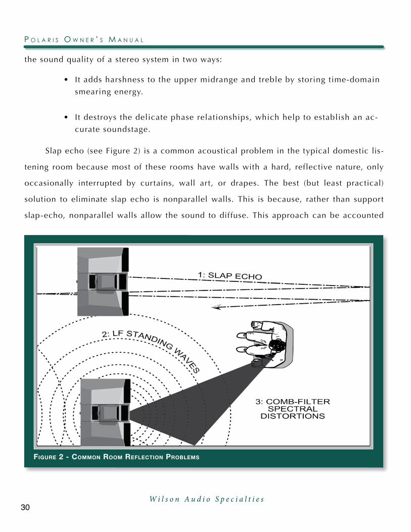
the sound quality of a stereo system in two ways:
•Itaddsharshnesstotheuppermidrangeandtreblebystoringtime-domain
smearing energy.
• Itdestroysthedelicatephaserelationships,whichhelptoestablishanac-
curate soundstage.
Slap echo (see Figure 2) is a common acoustical problem in the typical domestic lis-
tening room because most of these rooms have walls with a hard, reflective nature, only
occasionally interrupted by curtains, wall ar t, or drapes. The best (but least practical)
solution to eliminate slap echo is nonparallel walls. This is because, rather than support
slap-echo, nonparallel walls allow the sound to dif fuse. This approach can be accounted
figure 2 - coMMon rooM reflection ProbleMs
P o l a r i s o w n e r ’ s M a n u a l
30W i l s o n A u d i o S p e c i a l t i e s

for during the construction process. For existing rooms, slap echo can also be controlled
entirely by the application of absorptive materials to the hard surfaces. These are absorp-
tive materials that can be used to ameliorate slap echo:
•IllbruckSonex®
•Airductboard
•Corkpanels
•Largeceilingtofloordrapes
•Carpetingtowallsurfaces
In many domestic listening environments, heavy stuf fed furnishings reduce slap echo
somewhat. Unfortunately, their ef fectiveness is not predictable. Dif fusers are sometimes
also used to very good subjective ef fect, particularly in quite large rooms. Sound absor-
bent materials such as described above will alter the tonal characteristic of the room by
making it sound “deader,” less “bright and alive,” and “quieter.” These changes usually
make the room more pleasant for conversation, but sometimes render it too dull in the high
frequencies to be musically involving. Soundtrack ef fects will be more localized. However,
over-damping the room skews the tonal balance unnaturally toward the bass, and also com-
presses dynamics, robing the system of musical life excitement.
Dif fusers, on the other hand, do not af fect the tonal balance characteristic of the
room as much. Placed properly, dif fusers create a smoother and more open sound. Some
dif fusers, due to their construction, create narrow midrange peaks and suck out the warmth
region. Do not use dif fusers on the wall behind the speakers or on the sidewalls directly
beside the speakers. It is our experience that all of these room treatment devices should
be used judiciously.
31W i l s o n A u d i o S p e c i a l t i e s
s e C T i o n 3 . 2 – r o o M a C o u s T i C s

Standing Waves
Another type of reflection phenomenon is “standing waves.” Standing waves cause
the unnatural boosting or accentuation of certain frequencies, typically in the bass, to be
found at certain discreet locations in the room. These locations dif fer according to room
dimension and size. A room generating severe standing waves creates dif ficulty in setup. In
these rooms, the speaker will sound radically dif ferent as it is moved around. The ef fects
of standing waves on a loudspeaker’s performance are primarily in the areas listed.
•Tonalbalance
•Resolutionoflow-leveldetail
•Soundstaging
Standing waves are more dif ficult to correct than slap echo because they tend to oc-
cur at a lower frequency. Absorbent materials, such as Illbruck Sonex®, are inef fective at
controlling reflections in the bass region. Moving speakers about slightly in the room is, for
most people, their only control over standing waves. Sometimes a change of placement of
as lit tle as two or three inches can dramatically alter the tonal balance of a small system.
Fortunately, minor low frequency standing waves are well controlled by positioning
ASC Tube Traps™ in the corners of the room. Very serious low frequency accentuation
usually requires a custom-designed bass trap system.
Low frequency standing waves can be particularly troublesome in rooms constructed
of concrete or brick. These materials trap the bass in the room unless it is allowed to leak
out of the room through windows and doors.
In general, placement of the speaker in a corner will excite the maximal number of
standing waves in a room and is to be avoided for most direct radiator, full-range loud-
speaker systems. Some benefit is achieved by placing the stereo pair of loudspeakers
slightly asymmetrically in the listening room. This is so the standing waves caused by the
P o l a r i s o w n e r ’ s M a n u a l
32W i l s o n A u d i o S p e c i a l t i e s

distance between one speaker and its adjacent walls and floors are not the same as the
standing wave frequencies excited by the dimensions in the other channel.
Comb Filter Effect
The “comb filter” ef fect is a special type of standing wave noticeable primarily at
higher frequencies and shorter wavelengths.
Acoustical comb filtering occurs when sound from a single source, such as a loud-
speaker, is directed toward a microphone or listener from a distance. The first sound to
reach the microphone is the direct sound, followed by a delayed, reflected sound. At cer-
tain frequencies, cancellation occurs because the reflected sound lags in phase relative
to the direct sound. This cancellation is most apparent where the two frequencies are 180
degrees out of phase. Further, there is augmentation at other frequencies where the direct
and the reflected sounds arrive in phase. Because it is a function of wavelength, the comb
filter ef fect will notch out portions of the audio spectrum at linearly spaced intervals. Sub-
jectively, comb filter ef fect evidences itself as follows:
• Addedroughnesstothesound
• Reductionofharmonicrichness
• Smearingoflateralsoundstageimagefocusandplacement
Combfilteref fectsareof tencausedbysidewallreflections.Theyarebestcontrolled
by very careful speaker placement and by the judicious placement of Illbruck Sonex® or
air duct panels applied to that part of the wall where the reflection occurs.
Section 3.3 – Resonances
Resonance in listening rooms is generally caused by two sources:
•Structureswithinthelisteningroom.
33W i l s o n A u d i o S p e c i a l t i e s
s e C T i o n 3 . 3 – r e s o n a n C e s
•Thevolumeofairitselfwithinthelisteningroom.
Structural Resonance
Structural resonances are familiar to most people as buzzes and rat tles, but this type
of resonance usually only occurs at extremely high volume levels and is usually masked by
the music. In many wood frame rooms the most common type of structural resonance prob-
lem is “booming” of walls and floors. You can test for these very easily by tapping the wall
with the palm of your hand or stomping on the floor. Most rooms exhibit mid-bass “boom”
when struck. The loudspeaker playing in the room also excites these resonances. To give
you an idea of what the perfect wall would sound like, imagine rapping your hand against
the side of a mountain. Structural wall resonances generally occur in the low to mid-bass
frequencies and add a false fullness to the tonal balance. They, too, are more prominent
at louder levels, but their contribution to the sound of the speaker is more progressive.
Rat tling windows, picture frames, lamp shades, etc., can generally be silenced with small
pieces of caulk or with blocks of felt. However, short of actually adding additional layers
of sheet rock to flimsy walls, there is lit tle that can be done to eliminate wall resonances.
Volume Resonance
The physical dimensions and volume of air in a room will also support standing wave
modes and resonances at frequencies determined by the size of that room. Larger rooms
will resonate at a lower frequency and have more complex (bet ter) modal distributions
than will smaller rooms. Volume resonances, wall panel resonances, and low frequency
standing waves combine to form a low frequency coloration in the sound. At its worst, it is
a grossly exaggerated fullness, which tends to obscure detail and distort the natural tonal
balance of the speaker system.
Occasionally, however, there is just enough resonance to give a lit tle added warmth
tothesound–anadditionsomelistenersprefer.Carefulplacementofloudspeakersinthe
P o l a r i s o w n e r ’ s M a n u a l
34W i l s o n A u d i o S p e c i a l t i e s

room can dramatically reduce the speakers’ destructive interaction with low frequency
modes.ASCTubeTraps™areef fective in reducingsomeof this lowfrequencyroomcol-
oration.Customdesignedbasstraps,suchasperforatedHelmholtzresonators,providethe
greatest degree of low frequency control.
Section 3.4 – Your Room
Room Shapes
Standing waves are pressure waves propagated by the interaction of sound and op-
posing parallel walls. This interaction creates pat terns of low and high acoustical pressure
zones that accentuate and at tenuate particular frequencies. Those frequencies are depen-
dent on room size and dimension.
There are three basic shapes for most rooms: square, rectangular, and L-shaped (see
Figure 3).
A perfectly square room is the most dif ficult room in which to set up speakers. By vir-
figure 3 - Possible loudsPeaker PlaceMent within Various rooM shaPes
35W i l s o n A u d i o S p e c i a l t i e s
s e C T i o n 3 . 4 – Y o u r r o o M

tue of its shape, a square room is the perfect medium for building and sustaining standing
waves. These rooms heavily influence the music played by loudspeakers, greatly diminish-
ing the listening experience.
Long, narrow, rectangular rooms also pose their own special acoustical problems for
speaker setup. They have the ability to create several standing wave nodes, which will have
dif ferent standing wave frequency exaggerations depending on where you are sit ting. Ad-
ditionally, these long rooms are of ten quite lean in the bass near the center of the room.
Rectangular rooms are still preferred to square rooms because, by having two sets of dis-
similar length walls, standing waves are not as strongly reinforced and will dissipate more
quickly than in a square room. In these rooms, the preferred speaker position for spatial
placement and midrange resolution would be on the longer walls. Bass response would be
reinforced by speaker placement on the short walls.
In many cases, L-shaped rooms (see Figure 3) of fer the best environment for speaker
setup. Ideally, speakers should be set up along the primary (longest) leg of the room. They
should fire from the end of the leg (short wall) toward the L, or they should be along the
longest wall. In this way, both speakers are firing the same distance to the back wall. The
asymmetry of the walls in L-shaped rooms resists the buildup of standing waves (see Figure
3).
Polaris in a Dedicated Home Theater
Home theaters can be organized many dif ferent ways. Some use rows of couches.
Others use rows of multiple chairs.
In addition to watching movies, most users want to listen to two-channel music at the
highest quality possible. It is desirable, therefore, to choose a single optimum seating posi-
tion in a home theater and build the rest of the seating positions around this position.
If your optimum position is located on a couch, you should center the loudspeakers
on the middle position of the couch.
P o l a r i s o w n e r ’ s M a n u a l
36W i l s o n A u d i o S p e c i a l t i e s

If the seating area consists of more than two rows of chairs, typically the second row
should be optimized for the best sound quality. Odd numbers of chairs arranged in rows
work best as this will allow a single chair to be positioned in the center. This approach will
also provide the best overall sound for the greatest number of seats.
Speaker Placement Versus Listening Position
The location of your listening position is as important as the careful setup of your
Wilson Audio loudspeakers. The listening position should ideally be no more than 1.1 to
1.25 times the distance between the tweeters on each speaker. Therefore, in a long, rect-
angular room of 12’ x 18’, if the speaker tweeters are going to be 9’ apart, you should be
sit ting 9’11’’ to 11’3’’ from the speaker. This would be more than halfway down the long
axis of the room.
Many people place the speakers on one end and sit at the other end of the room.
This approachwill not yield the finest sound. Carefully consider your listening position.
Our experience has shown that any listening position that places your head closer than 14”
from a room boundary will diminish the sonic results of your listening.
Speaker Orientation
Speaker placement and orientation are two of the most important considerations in
obtaining superior sound. The first thing you need to do is eliminate the sidewalls as a
sonic influence in your system. Speakers placed too close to the sidewalls will suf fer from
a strong primary reflection. This can cause out-of-phase cancellations, or comb filtering,
which will cancel some frequencies and change the tonal balance of the music. The Wil-
son Audio Setup Procedure (Section 3.1) is the best method with which to position your
loudspeakers. Star t with the speakers about 18” from each wall (as measured from the rear
of the enclosure) and, if you need to move them relative to the side wall, move them away
from the wall, not closer.
37W i l s o n A u d i o S p e c i a l t i e s
s e C T i o n 3 . 4 – Y o u r r o o M

A very important aspect of speaker placement is how far from the back wall to place
the speakers. The closer a loudspeaker is to the back wall, the more pronounced the low
bass energy and centering of the image will be. However, this comes at a definite reduction
in stage size and bloom as well as a deterioration of upper bass quality. You must find the
proper balance of these two factors, but remember, if you are partial to bass response or
air and bloom, do not overcompensate your adjustments to maximize these ef fects. Over-
compensated systems are sometimes pleasing in the short-term, but long-term satisfaction
is always achieved through proper balance.
Polaris
After determining the general area for the Lef t and Right channels, determine the best
place for your Polaris. A poor placement of the Polaris will hamper its integration with the
rest of the system. As a general rule, when Polaris is used as a center channel, the distance
from the main Lef t and Right channels, as well as the Polaris (as measured from the tweet-
ers) should be equal in their relationship to the listening position. This maintains the time
coherence of the three front loudspeakers. Ultimately, the Polaris phase delay correction
will be made adjusting the midrange and Tweeter Modules.
When used as a center channel, Wilson recommends that the Polaris be positioned
between the Lef t and Right speakers as centrally possible. Using the Wilson Audio Setup
Procedure, experiment with the fore to af t placement of the Polaris. This process will help
you find the location that of fers the smoothest lef t, right, and Polaris integration.
P o l a r i s o w n e r ’ s M a n u a l
38W i l s o n A u d i o S p e c i a l t i e s

s e C T i o n 3 . 4 – Y o u r r o o M
39W i l s o n A u d i o S p e c i a l t i e s

W i l s o n A u d i o S p e c i a l t i e sW i l s o n A u d i o S p e c i a l t i e s

S e c t i o n 4 – I n i t i a l S e t u p


4343
Section 4.1 – Initial Assembly
In order to realize the capabilities of the Polaris, we strongly recommend that you
have it installed by a trained Wilson Audio installer. Your dealer will have a person trained
in the art of the Polaris installation. If you choose to do this installation yourself, here are
some guidelines to assist you. These guidelines come from many years of experience and
should be followed closely.
First,placetheWooferModulesintheZoneofNeutralityasdeterminedbythepro-
cedure outlined in Section 3.1. Remove the casters. Final setup and tuning will follow the
assembly of your Polaris.
Removing the Protective Film
Wilson Audio has applied a protective film with a special adhesive to protect the
paint surface of your loudspeakers. Please take the following precautions when removing
this film:
1. Ensure the speaker surface is room temperature before removing the protec-
tive film. Removing protective film when cold can damage the paint surface.
2. Slowly remove the film from the top down, large sections at a time, gently
pulling the film downward and outward. Tearing the film aggressively can
damage the paint.
3. Take care in removing the protective film near edges and corners to prevent
paint damage in these areas.
4. The protective film should not be lef t on the painted surface for extended
periods of time nor exposed to heat sources and direct sunlight.
W i l s o n A u d i o S p e c i a l t i e s
s e C T i o n 4 . 1 – i n i T i a l a s s e M b l Y

Section 4.2 – Geometric Time Domain Alignment
Materials Required
• Tapemeasure
• Knownlisteningposition(seeSection3)
• PolarisPropagationdelayAlignmentTablesfromSection10
Propagation delay Alignment
Propagation delay alignment accuracy of the Polaris has been established and verified
by Wilson Audio. The graphs and charts used in this section are a result of this testing.
Room Setup
As indicated in Figure 4, the Polaris system allows for dif ferent listening distances
(away from the speakers) and listening ear heights (measured distances from the floor to
your ear). For each distance/ear height combination there is a unique alignment geometry.
To make correct in-home set up of the Polaris possible without test equipment, Wilson
44
figure 4 – Measure listening distance and ear height�
ear heighT (measured From Floor)
lisTening disTance (measured on Floor)
P o l a r i s o w n e r ’ s M a n u a l
44W i l s o n A u d i o S p e c i a l t i e s

Audio has measured the correct geometric time domain alignment for dif ferent distance/
ear height combinations. This information is provided in the Propagation delay Tables in
Section 10. By measuring the ear height and the distance from the speaker to the listening
position, you will be able to align the system for your listening position.
Alignment Procedure
Locate the Alignment tables in Section 10. These tables contain critical information
that will guide you to position the upper modules for optimized propagation delay adjust-
ment.
Front-to-back alignment for each module is accomplished by resting the spike in a
specific indent. The Alignment plates are calibrated with numbered indents. There are also
four spike configurations for the Midrange Module, and two for the Tweeter Module which
rotate the head adjusting for proper axis alignment. The spike used depends on the dis-
tance/ear relationshipof the installation.The fourspike lengthsare labeled“B”,“C”,“D”
and “E” for theMidModule and “B” and “C” for the Tweeter. The alignment tables also
contain information on the front to back alignment of the midrange and Tweeter Modules.
This position is designated by the engraved numbers in the Spike mounting plate. Position
the module by aligning the Spike to the number indicated in the chart.
The Midrange Module’s front spike rests in a specific numbered indent that deter-
mines its individual propagation delay position within the modular array. The Tweeter
Module’s rear spike rests in a specific numbered indent that determines its individual
propagation delay position within the modular array. Each alignment plate beneath each
module contains numbered indents. The alignment tables contain the information for po-
sitioning each module in the array, determined by the indent in which the corresponding
spike rests. The table also contains information on the appropriate length spike to be used
in the rear of each module. In the case of the Midrange Module, two spikes of the correct
length must be used. Determine the alignment of each upper module as follows:
4545W i l s o n A u d i o S p e c i a l t i e s
s e C T i o n 4 . 2 – g e o M e T r i C T i M e d o M a i n a l i g n M e n T
1. If you are using the Polaris as ste-
reo pair, repeat each step of this
procedure on the lef t and right
channels simultaneously.
2. Remove the Propagation Delay
Tables from Section 10 in this
manual and place them close by
for easy reference.
3. Make sure that you are in your in-
tended listening position.
4. While sit ting, have someone mea-
sure your ear height from the floor
directly below your ear canal. You
should be relaxed in your chair,
as you would be when listening to
music (see Figure 4).
5. Nowmeasurethedistance(onthe
floor) from the point on the floor
below your ear to the base of the
loudspeaker, as shown in Figure
4.
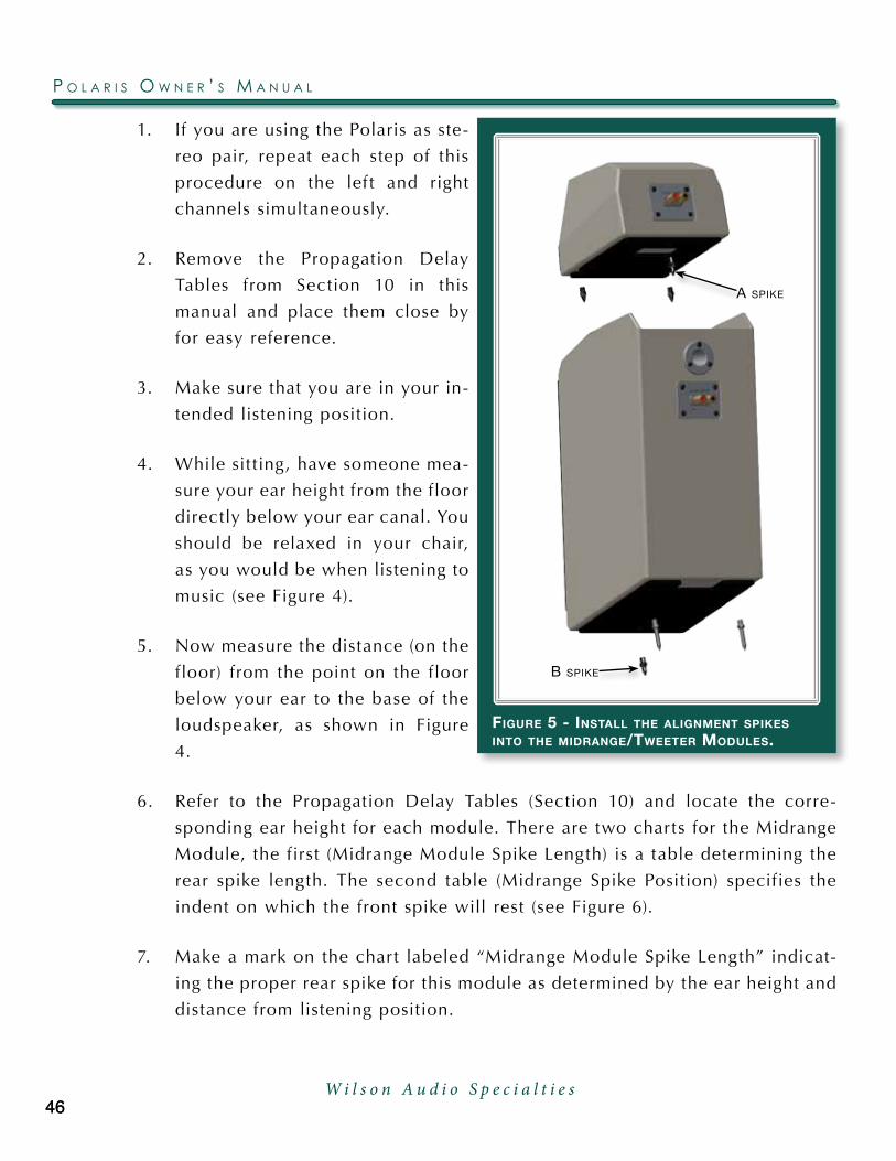
6. Refer to the Propagation Delay Tables (Section 10) and locate the corre-
sponding ear height for each module. There are two charts for the Midrange
Module, the first (Midrange Module Spike Length) is a table determining the
rear spike length. The second table (Midrange Spike Position) specifies the
indent on which the front spike will rest (see Figure 6).
7. Make a mark on the chart labeled “Midrange Module Spike Length” indicat-
ing the proper rear spike for this module as determined by the ear height and
distance from listening position.
46
figure 5 - install the alignMent sPikes into the Midrange/tweeter Modules�
b spike
a spike
P o l a r i s o w n e r ’ s M a n u a l
46W i l s o n A u d i o S p e c i a l t i e s
Note: The spike labeled B is always used in the front of the Midrange Module.
8. Make a mark on the labeled “Midrange Spike Position” table (Section 10)
indicating the indent on which the front spike of the lower module will rest.
Set this information aside as you will refer to it in the next section
Note: The tow spikes labeled A is always used in the front of the Tweeter Module.
9. There are two charts for the Tweeter Module, the first (labeled Tweeter Mod-
ule Spike Length) is a table determining the rear spike length. The second
is a table (labeled Tweeter Spike Location) determining the indent location.
47
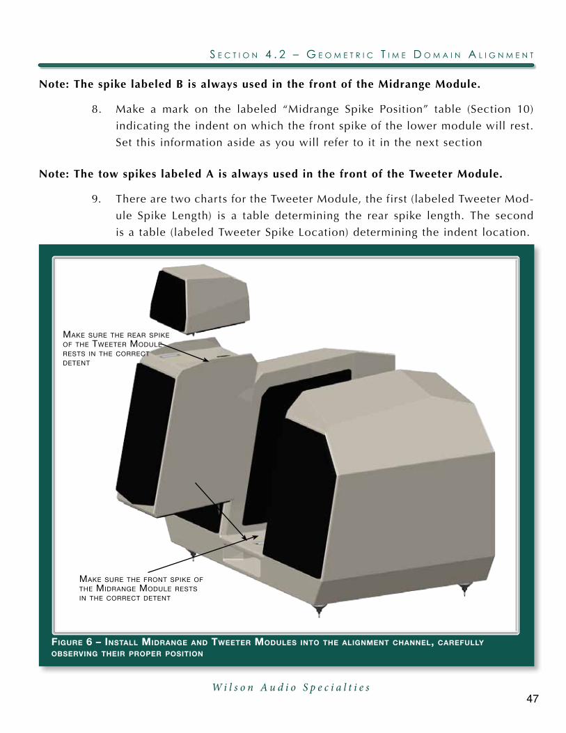
figure 6 – install Midrange and tweeter Modules into the alignMent channel, carefullY obserVing their ProPer Position
make sure The FronT spike oF The midrange module resTs in The correcT deTenT
make sure The rear spike oF The TweeTer module resTs in The correcT deTenT
s e C T i o n 4 . 2 – g e o M e T r i C T i M e d o M a i n a l i g n M e n T
W i l s o n A u d i o S p e c i a l t i e s

10. Make a mark on
the chart labeled
Number 3, “Tweet-
er Module Spike
Length” indicating
the proper rear spike
for this module as
determined by the
ear height and dis-
tance from listening
position.
11. Make a mark on
the table labeled
“Tweeter Module
Spike Detent Loca-
tion” indicating the
detent in which the
rear spike of the
Tweeter Module will
rest.
Section 4.3 – Mounting the Midrange Module
Materials Required
• Correctspikesforthemodules.RefertothePolarisPropagationdelay
Tables and the procedure in the previous section to determine the correct
Aspherical Propagation delay spikes necessary, the Spike position, and the
proper indent location.
Mounting Procedure
The front-to-back location of each module, along with the use of the proper length of
rear spike of the upper modules, achieves the correct propagation delay and axial response
48
figure 7 - sPike Position in the ProPagation delaY detent
P o l a r i s o w n e r ’ s M a n u a l
48W i l s o n A u d i o S p e c i a l t i e s

vis a vis the listener.
Install the rear “B” length spike into in the bottom of each module (see Figure 5).
Install the Midrange Module
The Midrange Module is installed first. Install the module as follows:
Note: Connect the midrange cable to the Midrange Module before installing the module
into the woofer enclosure. Locate the cable marked “Midrange” and connect this cable
to the Midrange Module’s binding post. This will make it easier to connect the cable to
the crossover module.
1. Turn the Midrange Module over, being careful not to damage the paint. There
are spike receptacles on the bottom of the Midrange Module, one in the
front, two in the rear.
2. Install the single B spike into the front receptacle. The front spike rests in a
specific detent in the alignment plate.
3. Refer toChart (Section10) labeledMidrangeModuleSpikeLength, and in-
stall the correct propagation delay spikes (there are two for the Midrange
Module) in the rear of the Module.
4. Refer to the table labeled “Midrange Spike Position.” The alignment plate is
located in the front of the channel between the two woofers (see Figure 6).
5. Position the Midrange Module inside the channel, placing the two rear spikes
into their corresponding slide tracks.
6. Tilt the front of the module up so you can see the correct spike detent on
the plate below.Carefully position the front spike of theMidrangeModule
in the correct detent.
Take caution not to scratch the painted surface with the alignment spike as you install
the Midrange Module.
49W i l s o n A u d i o S p e c i a l t i e s
s e C T i o n 4 . 3 – M o u n T i n g T h e M i d r a n g e M o d u l e

Section 4.4 – Mounting the Tweeter Module
1. RefertoChart(Section10)labeledTweeterModuleSpikeLength,andinstall
the correct propagation delay spike in the rear of the Tweeter Module.
2. Install two “A” spikes in the front of the module.
3. With the front pair of short spikes pointing down, carefully lower the Tweet-
er Module between the woofer and set the front two spikes on top of the
Midrange module. Align the spikes into the alignment tracks.
4. Refer to your mark on the table labeled Tweeter Module Spike Location, to
determine the proper location of the rear spike in its detent (see Figure 7),
noting that the position will be dif ferent from the Midrange Module.
5. Rest the rear spike in the proper detent (See Figure 7) as determined in the
previous step. Make sure that the front spikes stay in the front alignment
tracks so the paint surface on the top of the Midrange Module does not get
scratched.
Section 4.5 – Connecting Upper Modules’ Signal Cable
figure 10 - sPade lug attachMent
P o l a r i s o w n e r ’ s M a n u a l
50W i l s o n A u d i o S p e c i a l t i e s

The Polaris uses binding posts that were designed in-house and are manufactured ex-
clusively for Wilson Audio. The design goal was to create a connector with superior overall
sound quality, consistency, and longevity.
A note about these connectors: You risk breaking the binding post if they are overtight-
ened. Use the supplied binding post wrench and tighten until just snug.
The tweeter and Midrange Module signal cables are labeled so that they can be easily
at tached to their appropriate module. This is accomplished as follows:
• Themidrangecableshouldalreadybeconnectedtothemodule.Locatethe
binding post marked “midrange,” and connect this cable to the Midrange
output binding post, making sure to observe proper polarity.
• Locatethecablemarked“Tweeter,”andconnectittotheTweeterModule’s
binding post,which is on the rear of the Tweeter Module. In turn, connect
the other end of the cable to the Tweeter output on the Woofer Module.
Section 4.6 – Spike Installation
Note: We strongly recommend that your authorized Wilson Audio installer f inalize and
f ine tune your Polaris. Your dealer is trained in the art of the Polaris installation. If you
choose to adjust the Polaris on your own, before spiking your Polaris, refer to Section
3.1 which contains instruction on the Wilson Audio Setup Procedure (WASP).
Spike Assembly
1. Remove the mechanical diodes and move the nut to about two threads from
the point. This will allow for greater movement when leveling the loudspeak-
er system.
2. Screw the spikes into the diode until the nut is against the diode. Be careful
that the nut does not turn while inserting and threading spikes into the diode.
Note: Do not tighten these assembled spikes. You will need to unscrew them when you
level the Polaris.
51W i l s o n A u d i o S p e c i a l t i e s
s e C T i o n 4 . 6 – s P i k e i n s T a l l a T i o n

3. Place the set screw into the other end of the diode with the Allen head to-
ward the spike. This will ensure that if for any reason you have to remove
your Polaris spikes, you will be able to withdraw the set screw safely using
the supplied Allen wrench. Screw the set screw into the diode until it meets
the spike (see Figure 11).
4. Place the assemblies out of the work area until they are needed during the
installation.
Section 4.7 – Using the Lift to Install Spikes
Materials Required
Note: This is a two person job. Do not attempt this by yourself. The Polaris’s weigh over
400 LBS and may seriously injure someone if tipped over.
figure 11 - Polaris sPike and diode asseMblY
P o l a r i s o w n e r ’ s M a n u a l
52W i l s o n A u d i o S p e c i a l t i e s
• 4(8ifyouareusingthePolarisintwo-channelinstallation)setsofassem-
bled spikes
• TheWilsonAudioJack
• Thejacksocketwrench
• Swivelcasterwrench
Installation Procedure
5. Remove the midrange and Tweeter Modules.
6. Slide the Wilson Audio Jack under the front of the Polaris, centered between
the casters, so that the jack’s lif t bolt is exposed. Place the lif t plate so it is
positioned about an inch behind the front of the Polaris woofer enclosure.
7. Attach the wrench to the lif t bolt and begin to slowly raise the front of the
Polaris by turning the bolt clockwise.
8. Af ter the front of the Polaris is high enough (you will need approximately
one and half inches of clearance beneath the caster), use the swivel caster
wrench to loosen the casters. Remove the casters.
9. Insert and screw-in the finished spike assembly. Hand tighten only!
Note: Be very careful NOT TO CROSS THREAD the spikes. The base of the Polaris is
made of “X” material and is vulnerable to cross-threading.
• WithonepersonstabilizingthePolaris,lowerthePolarisbyturningthe
jackcounterclockwise.NotethatthePolariswillnowsitlowerinthefront
as the spike assembly is shorter than the caster. Use caution.
Note: It is very important, at this point, that an able assistant stabilize the front of the
Polaris until the rear spikes are attached and the unit is lowered.
53W i l s o n A u d i o S p e c i a l t i e s
s e C T i o n 4 . 7 – u s i n g T h e l i f T T o i n s T a l l s P i k e s

• IfyourareusingyourPolarisesinasleft/rightstereopair,repeattheprevi-
ous process of the caster removal/spike insertion on the opposite side of
the enclosure. Then continue the process on the other channel.
Leveling the Polaris
1. It is not necessary to use the jack to level the Polaris.
2. Place a level on the lef t to right oriented axis on the plane above the port. If
it is level, move to the next step.
3. If the bubble shows that the speaker is leaning toward the center of the
room, you will have to lengthen one of the inside spikes down toward the
figure 12 - carefullY thread the sPike asseMblY into the Pre-drilled holes
P o l a r i s o w n e r ’ s M a n u a l
54W i l s o n A u d i o S p e c i a l t i e s
floor. If the bubble is leaning toward the outside of the room, you will have
to lengthen one of the outside spikes down toward the floor.
4. Loosen the nut on the spike and rotate it the appropriate direction to length-
en the spike.
5. To find out which spike to lower, grasp the Polaris channel and rock it back
and forth. This will identify the spike that is out of level from the other three.
6. Reinstall the midrange and Tweeter Modules, taking care to ensure the cor-
rect propagation delay adjustments.
Section 4.8 – Resistors
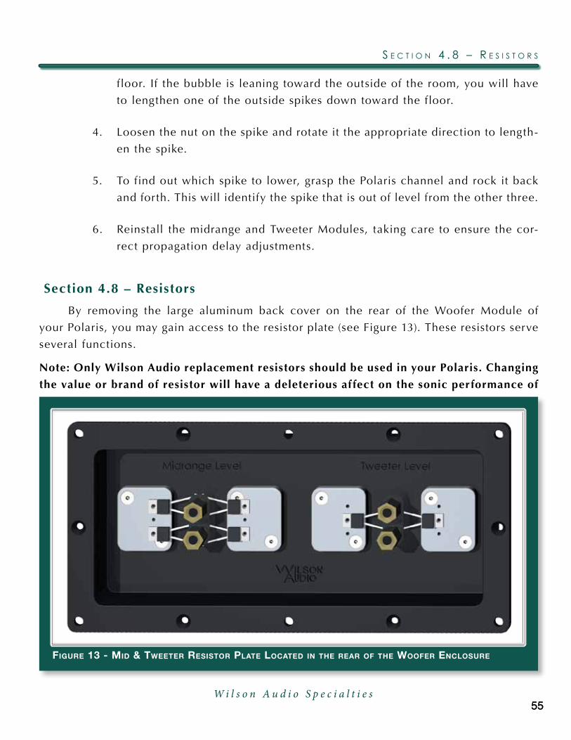
By removing the large aluminum back cover on the rear of the Woofer Module of
your Polaris, you may gain access to the resistor plate (see Figure 13). These resistors serve
several functions.
Note: Only Wilson Audio replacement resistors should be used in your Polaris. Changing
the value or brand of resistor will have a deleterious af fect on the sonic performance of
figure 13 - Mid & tweeter resistor Plate located in the rear of the woofer enclosure
55W i l s o n A u d i o S p e c i a l t i e s
s e C T i o n 4 . 8 – r e s i s T o r s
55

your loudspeakers and may void your Wilson Audio Warranty.
Midrange and Tweeter Resistors
The Midrange Level, which consists of two .5 ohm resistors in parallel, and Tweeter
Level, which consists of two 5.3 ohm resistors in parallel, resistors provide precise level
matching for the midrange and tweeter drivers correspondingly. The resistors also act as
ultra high quality fuses which open before a driver can be damaged by excess power. See
Section 8.1 for details in replacing these resistors in the event one of these resistors is
damaged.
Additionally, these resistors can be used to tailor the output of the corresponding
driver to overcome tonal balance issues that result from room acoustics.
Woofer Damping Resistor
resisTor access For midrange and TweeTer
main in binding posTs
figure 14 - Polaris cable connection
resisTor access For The wooFers
P o l a r i s o w n e r ’ s M a n u a l
56W i l s o n A u d i o S p e c i a l t i e s

The Woofer Damping resistor af fects the way the Polaris’s woofers couple to the am-
plifier. These resistors are pre-installed in a module behind the small trap door to the lef t
of the main resistor plate (Figure 14).
Section 4.9 – Break-in Period
All audio equipment will sound its best af ter its components have been broken in for
some period of use. Wilson Audio breaks in all woofers and mid-range drivers for a 12 hour
period. The drivers are then tested, calibrated, and matched for their acoustical properties.
In your listening room, expect 25 to 50 percent of break-in to be complete af ter two hours
of playing music fairly loudly. Ninety percent of break-in is complete af ter 24 hours of
playing. Playing a “disc repeat” overnight can accomplish this task quickly. Wilson Audio
recommends chamber music for this task.
57W i l s o n A u d i o S p e c i a l t i e s
s e C T i o n 4 . 9 – b r e a k - i n P e r i o d

W i l s o n A u d i o S p e c i a l t i e sW i l s o n A u d i o S p e c i a l t i e s

S e c t i o n 5 – F i n a l S e t u p


6161
Section 5.1 – Tips for Final Tuning and Voicing, Home Theater
This loudspeaker placement method was developed by David A. Wilson, for Wilson
Audio Specialties, Inc., to find optimum loudspeaker locations in any given room within
one hour. Participating in numerous audio/multi-channel/home theater shows with very
dif ferent and dif ficult acoustic environments necessitated this procedure. Currently, all
Wilson Audio dealers employ this setup procedure for their customers, in order to quickly
and predictably achieve the best performance from their systems (this procedure can be
usedsuccessfullywithANYmovingcoilspeakersystem).
Proper system calibration is the most important step in the setup of your multi-
channel/hometheatersystem.TheWATCHsystemof fers increasedresolutionandoverall
system performance. This increased resolution allows you to fine tune your system, thus
increasing overall performance, more than any other system available.
Fine tuning and “voicing” generally involve only small changes in location and ro-
tation (or toe) of your multi-channel system. With proper calibration you will find that
changes as small as 1 inch will have an impact on the performance of your system. The
following sections will step you through this fine tuning process. The setup will be done
as follows:
•SetuptheLeftandRightchannelswithallotherspeakersdisconnected.
•AddthePolaris.
•Addthesurroundchannels.
•Addthesubwoofer.
Adding one speaker at a time will allow you to easily evaluate the integration with
the system and make the necessary adjustments to fine tune the setup.
W i l s o n A u d i o S p e c i a l t i e s
s e C T i o n 5 . 1 – T i P s f o r f i n a l T u n i n g a n d V o i C i n g , h o M e T h e a T e r
Section 5.2 - Left and Right Channels
Determining Front to Back Distance
The proper setup of the lef t and right channels is crucial for optimum system perfor-
mance. If these speakers are not set up correctly, the entire system will suf fer from poor
integration. Please follow these steps carefully:
•Placethespeakerinanappropriatelocationrelativetoyourscreenandlis-
tening area. Make certain to remove the grills and spikes.
•Toethespeakersinsothatyoucanjustbarelyseetheinsideedgewhen
seated in the primary listening position.
•Usingremovablemaskingtape,graphoffthefloorsothatyoucanaccurate-
ly move both speakers forward and backward in 1/2 inch increments.
•Placeyourmulti-channelprocessorintostereomode.
•Usingapieceoffullrangemusic(dynamicwithalotoflowfrequencyin-
formation) played at a moderately high level, take notes on the sound qual-
ity. Pay specific attention to upper and lower bass quality, dynamic con-
trasts, image height, and focus.
•Movethespeakersbackorforwardin1inchincrementsandthen1/2inch
increments.
Note: Moving the speakers BACK will generally increase low bass, sharpen focus, lower
image height, and increase dynamics up to the point where you go too far, in which
case the sound will start to lose these qualities in addition to becoming boomy and
slow sounding. Moving the speakers FORWARD will increase air and bloom, raise im-
age height, and generally increase the sense of space. Moving too far forward will cause
the soundstage to become unnaturally high with a lack of focus, dynamics, and low-end
extension.
P o l a r i s o w n e r ’ s M a n u a l
62W i l s o n A u d i o S p e c i a l t i e s

•Findthefronttobacklocationwherethebassistight,dynamicsarecor-
rect, image is well-focused, and you find the best soundstaging. Mark this
as your final front to back location.
Determining Side to Side Distance
The distance the speakers are from the side walls is very important. This distance de-
termines the amount of comb filtering you will hear. In ef fect, you are “tuning” the comb
filter interaction between the speaker and the wall. Perform the side to side analysis as
follows:
•Placeapieceoftapeonthefloorparalleltothefrontedgeofthespeaker
and again mark off 1/2 inch increments side to side.
•Usingonlyonechannel/speakeratatime,nowdeterminetheoptimumpo-
sition with regard to side walls.
Note: A high quality, solo piano recording works well for this step.
•Whilemusicisplaying,slowlymovethespeakersleftorright1inchthen
1/2 inch at a time until you achieve the best harmonic integrity.
You should not need to move the speaker any more than one inch lef t or right from
the original location. Do this independently for each channel. What you will hear when the
speaker moves into the correct location is a reduction of hardness and muddied harmonics
from the piano.
Note: If you continue moving the speaker past this point, you will begin to hear again
this fatiguing artifact.
When you have determined the optimum location for each speaker, mark it carefully,
and make certain the toe-in is correct. When installing the spikes, the speakers may shif t
slightly, but you can move them precisely back to the correct location again using your
tape markers.
63W i l s o n A u d i o S p e c i a l t i e s
s e C T i o n 5 . 2 - l e f T a n d r i g h T C h a n n e l ss e C T i o n 5 . 2 - l e f T a n d r i g h T C h a n n e l s

Section 5.3 - Integrating the Polaris into a Wilson Theater
Note: Many processors offer a setup guide that steps you through the integration of each
of the speakers, specif ically, setting speaker distances, delays, and phase rotation. These
adjustments are made via internal electrical adjustments. We have found that actual
geometric changes, that is, moving the speaker location and rotation, offer improved
results when integrating speakers. We recommend that you follow the steps outlined
below, evaluate your system performance, and then make adjustments in the processor.
Ultimately, you will, of course, need to make level adjustments via the processor.
Integrating the Polaris as a center channel
The next step in the setup process is to fine tune the location and rotation of the Po-
laris. Do as follows:
•PlacethePolariscenteredbetweenthemainspeakersandevenwiththe
front inner edge. Set the alignment spikes as indicated in Section 10.
•Followtheprocessorinstructionsonleveladjustment.Adjustthelevelon
the Polaris so it matches in level with the left and right channels. Do not
be surprised if the Polaris requires 3-7 dB lower adjustment than the left
and right channel.
•MakesurethatonlythefrontLeft,RightandPolarisareconnected.
•WiththePolarisspiked,putonamulti-channelaudiotrackormoviescene
with which you are familiar.
•Playtheselectionandlistenfortheintegrationwiththemainspeakers.As
the audio moves across the three front speakers, listen for a smooth tran-
sition from one speaker to the next. You should not hear any voids in the
sound stage.
•Make1/2”changesinfronttobacklocationuntilyoufindthePolarisloca-
tion that offers the best integration.
P o l a r i s o w n e r ’ s M a n u a l
64W i l s o n A u d i o S p e c i a l t i e s

Image Height
Check the imageheight.Does thedialogueofamoviehave thecorrectheight? Is it
toolowortoohigh?
If needed, adjust the amount of rotation until the image height is correct. Raising
the front spikes will raise the image height; lowering the front spikes will lower the image
height. Where possible, we recommend that you add or remove a spacer to get the correct
image height. This will allow the propagation delay alignment to be reset using the tables
in Section 10.
Correct Polarity
Using a pink noise generator, play pink noise through the Polaris together with alter-
nating Lef t and Right channels. If the polarity is correct on the Polaris, you will hear the
pink noise centered between the Polaris and either the Lef t or Right speakers. If the polar-
ity is incorrect, you will hear two point sources that are unfocused and located at each
speaker playing.
Integrating the WATCH Surround Channels
•Followtheprocessorinstructionsonleveladjustment.Adjustthelevelon
the Surround channels so they match in level with the front channels.
•PlayaDVDthathasascenewithsomethingmovingaroundtheroom.Lis-
ten for the correct spacial imaging. A correctly adjusted Surround channel
will have good imaging characteristics, will be seamlessly blended, and
should be just as transparent as the front channels.
•AdjusttherotationoftheSurroundchanneluntilyoufindthebestintegra-
tion.
Note: The Surround channel rotates on the upper two spikes. Examine carefully
this rotation and the mounting bracket before trying to adjust the angle of rota-
65W i l s o n A u d i o S p e c i a l t i e s
s e C T i o n 5 . 3 - i n T e g r a T i n g T h e P o l a r i s i n T o a w i l s o n T h e a T e r
tion. Be careful when rotating the speaker as it is very heavy and could fall off of
the mounting bracket.
Integrating the Passive WATCH Dog or Thor’s Hammer
TheWATCHDogorThor’sHammerwill performwell in almost any location in the
room. In general, the closer you place the subwoofer to a wall or corner, the greater the
augmentation of the bass. However, the increase in bass comes at a cost of perceived
speed, dynamics and bass clarity. We recommend that you experiment with the placement
of the subwoofer to find a balance of the above mentioned items with which you are satis-
fied.ForcompleteinformationonintegratingaWilsonAudioWATCHDogorThor’sHam-
mer, please refer to your subwoofer owner’s manual.
P o l a r i s o w n e r ’ s M a n u a l
66W i l s o n A u d i o S p e c i a l t i e s

s e C T i o n 5 . 3 - i n T e g r a T i n g T h e P o l a r i s i n T o a w i l s o n T h e a T e r
67W i l s o n A u d i o S p e c i a l t i e s

W i l s o n A u d i o S p e c i a l t i e sW i l s o n A u d i o S p e c i a l t i e s

S e c t i o n 6 – C a r e o f P o l a r i s

Section 6.1 – Care of the Finish
ThePolarisloudspeakerishandpaintedwithWilsonGloss™paintandhandpolished
to a high luster. While the finish seems quite dry to the touch, final curing and complete
hardening takes place over a period of several weeks.
Dusting the Polaris
It is important that the delicate paint finish of the Polaris be dusted carefully with
the dust cloth, which has been provided. We recommend that the following procedure be
observed when dusting the speakers:
• Blowoffallloosedust.
• Usingthespecialdustclothasabrush,gentlywhiskoffanyremaining
loose dust.
• Shakeoutthedustcloth.
• Dustthefinish,usinglinearmotionsinonedirectionparalleltothefloor.
Avoid using circular or vertical motions.
Because the paint requires a period of several weeks to fully cure, we recommend that
no cleaning fluids, such as glass cleaners, be used during this initial period of time. When
the paint is fully cured, heavy fingerprints and other minor smudges may be removed with
a glass cleaner. Always use the dust cloth. Stronger solvents are not recommended under
anycircumstances.Consultyourdealerforfur therinformationifrequired.Tomaintainthe
high luster of the finish, periodic polishing may be desired. We recommend a nonabrasive
carnauba-based wax and a sof t cloth.
Care of the Grills
Periodically, you will want to clean the Polaris’s grills. This is best done by using the
71W i l s o n A u d i o S p e c i a l t i e s
s e C T i o n 6 . 1 – C a r e o f T h e f i n i s h
round brush at tachment on a vacuum cleaner hose. Gently vacuum the front surface of
the grill. Be careful not to apply too much pressure. Do not use a hard plastic at tachment
against the grill. The grill cloth is stretched tightly over the grill frame. Too much pressure
or use of a hard plastic at tachment could cause the grill material to tear, especially in the
corners.
Often Wilson speaker owners desire to change the look of their listening room by
changing the color of their speaker grills. In addition to basic black, Wilson Audio of fers
avarietyofgrillcolors tomatchmostWilsonGloss finishes.Contactyour localdealer for
grill cloth samples or to order replacement grills for your Polaris.
Section 6.2 – Enclosure Technology
Materials
Wilson Audio has conducted many hours of research on the impact of materials on
speaker enclosure performance. Through this ef fort, Wilson pioneered the use of non-reso-
nant materials, first with the use of mineral-filled acrylic in the WATT and continuing with
the further development of proprietary materials for X-1 Grand SLAMM, MAXX, Sophia.
Throughout this time, the Wilson engineering team continues to work with outside vendors
to refine and evolve these composites. With Sasha, Wilson introduced its latest composite,
dubbed internally “S” Material. Like the materials before it, “S” redefines what is possible
in low-resonance materials. Polaris joins Sasha in the use of “S” material in its midrange
baf fle. Even the best materials are not suited to all aspects of enclosure construction.
Therefore, like all Wilson loudspeakers, the Polaris is constructed of several exotic materi-
als, including Wilson’s X-material, each chosen for their specific performance at tributes
relevant to dif ferent portions of the enclosure.
The Polaris is constructed using non-resonant, high-density, composites which are
then cross-braced to further reduce cabinet resonance. Each of these composites meets
P o l a r i s o w n e r ’ s M a n u a l
72W i l s o n A u d i o S p e c i a l t i e s

andexceeds thehighestofANSI test standards for itsuse,whileof feringvery tight toler-
ances, high hardness, uniform density, and dimensional stability.
Adhesive
Wilson Audio has conducted exhaustive research into the best adhesives to perma-
nently bond our speaker enclosures. This is of ten an overlooked element crucial to the
properperformanceofaloudspeaker.Correctmodulusofelasticity,coef ficientofthermal
expansion, and natural frequency response are just a few of the important elements of ad-
hesives.
A highly cross-linked, thermoset adhesive is used for the construction of the enclo-
sure. It was also chosen for its excellent bond strength, solvent resistance, hardness, and
optimum vibrational characteristics.
Section 6.3 – Depth of Design
Polaris’s compellingly authentic performance and lasting value are achieved through
careful implementation of cut ting edge design and engineering and then executed using
the highest performance materials. Wilson Audio’s use of proprietary enclosure materials
and adhesives are employed to achieve truly exceptional speaker cabinet performance. The
use of these materials in the Polaris results in an enclosure that is inherently inert and low-
resonant. All of these structural aspects are combined, allowing Wilson Audio to deliver
a product that maintains the strictest structural tolerances, durability, and reliability. This
also means that the Polaris will have consistent, repeatable performance, unaf fected by the
climatic conditions, anywhere in the world. Finally, like all Wilson products, the Polaris
is hand-craf ted with meticulous at tention to detail, with an unwavering commitment to
excellence. Thus, the Polaris will impart to her owner beauty and pleasure for many years
to come.
73W i l s o n A u d i o S p e c i a l t i e s
s e C T i o n 6 . 3 – d e P T h o f d e s i g n

W i l s o n A u d i o S p e c i a l t i e sW i l s o n A u d i o S p e c i a l t i e s

S e c t i o n 7 – T r o u b l e s h o o t i n g

Polaris is not operating:
Driver out or not playing after connec-
tions have been verif ied:
Amplif ier shuts off as soon as it is turned on:
Ch e c k t h e i n t e r c o n n e c t s f r om t h es o u r c e .
Ch e c k t h e c o n n e c t i o n s o n t h e s p e a k -e r c a b l e s , b o t h a t t h e a m p l i f i e r a n d s p e a k e r e n d s . W a t c h e s p e c i a l l y f o r c o n n e c t o r s t o u c h i n g e a c h o t h e r .
I f y o u h a v e f o u n d a d r i v e r w i t h n o o u t p u t , t u r n o f f y o u r a m p a n d d i s -c o n n e c t t h e s p e a k e r c a b l e . R e f e r t o s e c t i o n 8 . 1 , w h i c h d i s c u s s e s r e p l a c -i n g a n d o p e n r e s i s t o r .
U s i n g t h e a p p r o p r i a t e A l l e n k e y, o p e n t h e d o o r o n t h e b a c k .
Yo u w i l l f i n d s o m e r e s i s t o r c o n n e c -t i o n s . R e p l a c e t h e r e s i s t o r w i t h t h e s u p p l i e d m a t c h i n g r e s i s t o r . Ti g h t -e n t h e n e w r e s i s t o r i n t h e o l d o n e ’s p l a c e .
N o t e : U s e o n l y W i l s o n A u d i o r e -p l a c e m e n t r e s i s t o r s i n y o u r Po l a r i s . Th e s e r e s i s t o r s w e r e c a r e f u l l y c h o -s e n f o r t h e o v e r a l l s o n i c a n d t h e r -m a l p e r f o r m a n c e .
P l u g y o u r a m p l i f i e r i n t o t h e w a l l a n d t u r n i t o n .
L i s t e n t o t h e Po l a r i s a t a l o w l e v e l . Th e d r i v e r s h o u l d n o w b e o p e r a t i n g c o r r e c t l y.
Ch e c k t o s e e i f y o u r s p e a k e r c a b l e sa r e p r o p e r l y c o n n e c t e d t o t h e b i n d -i n g p o s t s . L o o k f o r f r a y e d e n d s , l o o s e c o n n e c t i o n s , o r a c o n d u c t o r c o n t a c t -
Section 7.1 – Troubleshooting:
77W i l s o n A u d i o S p e c i a l t i e s
s e C T i o n 7 . 1 – T r o u b l e s h o o T i n g :

If the problem is solved:
If the problem persists:
If the problem is solved:
If the problem persists:
If the problem is solved:
If the problem persists:
i n g t h e a m p l i f i e r c h a s s i s .
Tu r n t h e a m p l i f i e r o f f a n d d i s c o n n e c t i t f r om t h e AC wa l l o u t l e t . D i s c o n -n e c t t h e p r e a m p l i f i e r l e a d s t o t h e amp l i f i e r . N ow t u r n o n t h e am p l i f i e r .
Th e r e i s l i k e l y s o m e t h i n g w r o n g w i t h y o u r p r e a m p l i f i e r o r i n t e r c o n n e c t . Co n t a c t y o u r d e a l e r .
L e a v e t h e p r e a m p l e a d s d i s c o n n e c t e d a n d c o n t i n u e t o t h e n e x t s t e p .
Tu r n t h e a m p l i f i e r o f f . D i s c o n n e c t t h e s p e a k e r l e a d s a t t h e m a i n i n p u t t o t h e s p e a k e r . N ow t u r n o n t h e am -p l i f i e r .
C a l l y o u r W i l s o n Au d i o d e a l e r . Th e r em a y b e a p r o b l e m w i t h t h e c r o s s o v e r o r t h e s p e a k e r ’s i n t e r n a l w i r i n g .
Co n t i n u e t o t h e n e x t s t e p .
Tu r n t h e a m p l i f i e r o f f a n d d i s c o n n e c t i t f r om t h e AC wa l l o u t l e t . D i s c o n -n e c t t h e s p e a k e r c a b l e l e a d s t o t h e a m p l i f i e r a n d t u r n t h e a m p l i f i e r o n a g a i n .
Yo u h a v e a s h o r t i n y o u r s p e a k e r c a -b l e s . C h e c k f o r f r a y e d e n d s , h o l e s( f r o m s p i k e f e e t ) , o r m a k e s u r e t h a t y o u r s p a d e l u g i s n o t t o u c h i n g t h e c h a s s i s w h i l e i t i s c o n n e c t e d t o t h e b i n d i n g p o s t .
C a l l t h e d e a l e r wh e r e y o u b o u g h ty o u r a m p l i f i e r . Yo u a p p e a r t o h a v e a p r o b l e m w i t h t h i s c o m p o n e n t .
P o l a r i s o w n e r ’ s M a n u a l
78W i l s o n A u d i o S p e c i a l t i e s

s e C T i o n 7 . 1 – T r o u b l e s h o o T i n g :
79W i l s o n A u d i o S p e c i a l t i e s

W i l s o n A u d i o S p e c i a l t i e sW i l s o n A u d i o S p e c i a l t i e s

S e c t i o n 8 - R e p a i r P r o c e d u r e s


Section 8.1 - Repair Procedures
Replacing a Blown Resistor
The Polaris tweeter and midrange drivers are protected by resistors, which will open,
in most cases if the speaker is over driven during normal operation before the driver is
damaged.
Replace a blown resistor as follows:
1. Determine which driver is not playing functioning properly.
2. Remove the appropriate resistor access cover from the enclosure by remov-
ing each of the 10-32 button head machine screws (see Section 4 for resistor
cover locations).
3. The midrange and tweeter resistor are labeled accordingly. Locate the blown
figure 15 - Mid & tweeter resistor Plate located in the rear of the woofer enclosure
83W i l s o n A u d i o S p e c i a l t i e s
s e C T i o n 8 . 1 - r e P a i r P r o C e d u r e s
resistor.
4. Remove the allen bolts at taching the resistor to its heatsinks.
5. Using the 5/8” nutdriver, loosen the binding post and remove the open resis-
tor. (See Figure 15.)
6. Replace the resistor with a Wilson spec’d unit, at taching it to the binding
post and heatsinks as before.
7. Re-at tach the resistor access cover to the enclosure, making sure not to over
tighten the screws.
Replacing a Damaged Driver
If you believe that a driver is blown, make sure that you have tried replacing the pro-
tective resistor before you replace the driver. No sound coming from a driver is of ten a
blown resistor and not a bad driver. If you need to replace a driver, do so as follows:
1. Using the supplied Allen wrench, remove the machine screws holding the
driver in place.
2. Insert the Allen wrench into one of the driver screw holes 1/8 inch. Gently
lif t out the driver, and place it onto the foam pad covering the front baf fle.
Note: It is best to place an old towel under the driver so that you will not dam-
age the enclosure when un-soldering the driver.
3. Using a 900 degree F soldering iron, heat up the solder joints and remove
the driver.
4. Melt a small 1/8” diameter bead of solder onto the tip of each wire. Heat the
wire up until you see the solder wick into the copper.
5. Place the replacement driver onto the cloth and solder on the wires to the
driver. The white wire connects to the positive side, and the black wire con-
nects to the negative. The positive side is generally indicated by a red dot.
P o l a r i s o w n e r ’ s M a n u a l
84W i l s o n A u d i o S p e c i a l t i e s

Make sure to heat up the solder joint completely and hold firmly in place
until the solder sets.
6. Replace the driver foam gasket.
7. Place the driver into the machined recess.
8. Replace the machine screws, tightening them to 15 inch/pounds (not foot
pounds) of torque.
Note: Be careful not to over tighten the screws.
s e C T i o n 8 . 1 - r e P a i r P r o C e d u r e s
85W i l s o n A u d i o S p e c i a l t i e s

W i l s o n A u d i o S p e c i a l t i e sW i l s o n A u d i o S p e c i a l t i e s

S e c t i o n 9 – S p e c i f i c a t i o n s


Section 9.1 - Polaris Specifications
Enclosure Type:Woofer:
Midrange:
Tweeter:
Drivers:Woofers:
Midranges:
Tweeter:
Measurements:Impedance:
Sensitivity:
Frequency Response:
Dimensions:Polaris Height:
Polaris Depth:
Polaris Width:
Speaker Weight Uncrated:
Shipping Weight (approximate):
Front Ported
Rear Ported
Sealed Tweeter Drive Unit
Two – 9.5 inch (24.13 cm)
Two – 7 inch (17.78 cm)
1 inch inverted dome (2.54 cm)
4 ohms, 2.2 ohms minimum @ 49 Hz
94 dB @ 1 watt @ one meter @ 1 kHz
+/- 3 dB 20 Hz - 21 kHz Room Average Response
28.5 inches (72.39 cm) w/o spikes
30.75 inches (78.11 cm) with spikes
25 inches (63.33 cm)
38 inches (96.52 cm)
294 lbs (133.36 kg)
485 lbs (219.99 kg)
89W i l s o n A u d i o S p e c i a l t i e s
s e C T i o n 9 . 1 - P o l a r i s s P e C i f i C a T i o n s
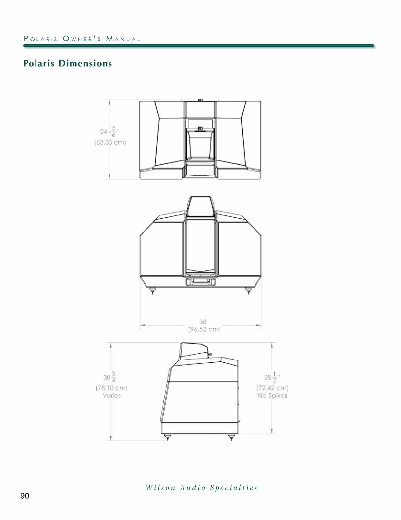
Polaris Dimensions
P o l a r i s o w n e r ’ s M a n u a l
90W i l s o n A u d i o S p e c i a l t i e s

Polaris Impedance Curve
91W i l s o n A u d i o S p e c i a l t i e s
P o l a r i s i M P e d a n C e C u r V e

W i l s o n A u d i o S p e c i a l t i e sW i l s o n A u d i o S p e c i a l t i e s

S e c t i o n 1 0 – A l i g n m e n t T a b l e s


Note: Always install the “B” length spike into in the bottom front of Midrange Module.
Polar
is M
id S
pike
Len
gth
Ear
Heigh
t8'
9'10
'11
'12
'13
'14
'15
'16
'17
'18
'19
'20
'21
'22
'23
'24
'25
'26
'27
'28
'29
'30
'31
'32
'
36"
CC
CD
DD
EE
D (See
No
te 5)
D (See
No
te 5)
E (See
No
te 5)
E (See
No
te 5)
E (See
No
te 5)
E (See
No
te 5)
E (See
No
te 5)
E (See
No
te 5)
E (See
No
te 5)
N/A
N/A
N/A
N/A
N/A
N/A
N/A
N/A
38"
BC
CD
DD
DD
E
D (See
No
te 5)
D (See
No
te 5)
E (See
No
te 5)
E (See
No
te 5)
E (See
No
te 5)
E (See
No
te 5)
E (See
No
te 5)
E (See
No
te 5)
N/A
N/A
N/A
N/A
N/A
N/A
N/A
N/A
40"
C (See
No
te 2)
CC
CD
DD
DD
E
D (See
No
te 5)
D (See
No
te 5)
D (See
No
te 5)
E (See
No
te 5)
E (See
No
te 5)
E (See
No
te 5)
E (See
No
te 5)
N/A
N/A
N/A
N/A
N/A
N/A
N/A
N/A
42"
B (See
No
te 2)
BC
CC
DD
DD
DE
E
D (See
No
te 5)
D (See
No
te 5)
D (See
No
te 5)
E (See
No
te 5)
E (See
No
te 5)
E (See
No
te 5)
N/A
N/A
N/A
N/A
N/A
N/A
N/A
44"
B (See
No
te 3)
C (See
No
te 2)
BC
CD
DD
DD
DD
E
D (See
No
te 5)
D (See
No
te 5)
D (See
No
te 5)
E (See
No
te 5)
E (See
No
te 5)
E (See
No
te 5)
E (See
No
te 5)
N/A
N/A
N/A
N/A
N/A
46"
C (See
No
te 4)
B (See
No
te 2)
BC
CC
DD
DD
DD
DE
E
D (See
No
te 5)
D (See
No
te 5)
D (See
No
te 5)
E (See
No
te 5)
E (See
No
te 5)
E (See
No
te 5)
E (See
No
te 5)
N/A
N/A
N/A
48"
B (See
No
te 4)
B (See
No
te 3)
C (See
No
te 2)
BC
CC
DD
DD
DD
DE
E
D (See
No
te 5)
D (See
No
te 5)
D (See
No
te 5)
E (See
No
te 5)
E (See
No
te 5)
E (See
No
te 5)
E (See
No
te 5)
E (See
No
te 5)
N/A
50"
N/A
N/A
B (See
No
te 2)
C (See
No
te 2)
CC
CC
DD
DD
DD
DE
EE
D (See
No
te 5)
D (See
No
te 5)
D (See
No
te 5)
E (See
No
te 5)
E (See
No
te 5)
E (See
No
te 5)
E (See
No
te 5)
52"
N/A
N/A
N/A
B (See
No
te 2)
C (See
No
te 2)
CC
CC
DD
DD
DD
DD
EE
D (See
No
te 5)
D (See
No
te 5)
D (See
No
te 5)
D (See
No
te 5)
E (See
No
te 5)
E (See
No
te 5)
54"
N/A
N/A
N/A
N/A
C (See
No
te 2)
C (See
No
te 2)
CC
CC
DD
DD
DD
DD
EE
D (See
No
te 5)
D (See
No
te 5)
D (See
No
te 5)
D (See
No
te 5)
D (See
No
te 5)
56"
N/A
N/A
N/A
N/A
N/A
C (See
No
te 2)
C (See
No
te 2)
CC
CC
DD
DD
DD
DD
EE
E
D (See
No
te 5)
D (See
No
te 5)
D (See
No
te 5)
58"
N/A
N/A
N/A
N/A
N/A
N/A
C (See
No
te 2)
CC
CC
CD
DD
DD
DD
DD
EE
D (See
No
te 5)
D (See
No
te 5)
60"
N/A
N/A
N/A
N/A
N/A
N/A
N/A
C (See
No
te 2)
CC
CC
CD
DD
DD
DD
DD
EE
E
Liste
ning
Dist
ance
s e C T i o n 1 0 . 1 – P o l a r i s P r o P a g a T i o n d e l a Y T a b l e
95W i l s o n A u d i o S p e c i a l t i e s
s e C T i o n 1 0 . 1 – P o l a r i s P r o P a g a T i o n d e l a Y T a b l e
W i l s o n A u d i o S p e c i a l t i e s
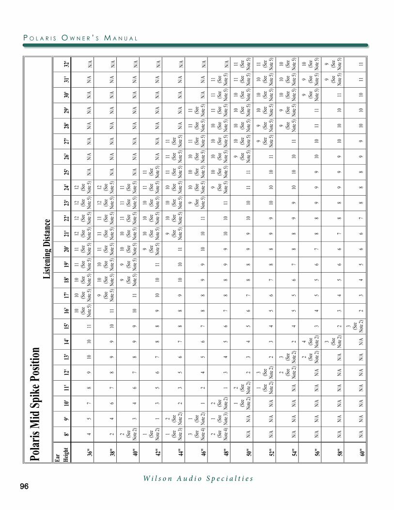
Pola
ris M
id S
pike
Pos
ition
Ear
Heig
ht8'
9'10
'11
'12
'13
'14
'15
'16
'17
'18
'19
'20
'21
'22
'23
'24
'25
'26
'27
'28
'29
'30
'31
'32
'
36"
45
78
910
1011
10 (See
No
te 5)
10 (See
No
te 5)
10 (See
No
te 5)
11 (See
No
te 5)
11 (See
No
te 5)
12 (See
No
te 5)
12 (See
No
te 5)
12 (See
No
te 5)
12 (See
No
te 5)
N/A
N/A
N/A
N/A
N/A
N/A
N/A
N/A
38"
24
67
89
910
11
9 (See
No
te 5)
10 (See
No
te 5)
10 (See
No
te 5)
11 (See
No
te 5)
11 (See
No
te 5)
11 (See
No
te 5)
12 (See
No
te 5)
12 (See
No
te 5)
N/A
N/A
N/A
N/A
N/A
N/A
N/A
N/A
40"
2 (See
No
te 2)
34
67
89
910
11
9 (See
No
te 5)
9 (See
No
te 5)
10 (See
No
te 5)
10 (See
No
te 5)
11 (See
No
te 5)
11 (See
No
te 5)
11 (See
No
te 5)
N/A
N/A
N/A
N/A
N/A
N/A
N/A
N/A
42"
1 (See
No
te 2)
13
56
78
89
1010
11
9 (See
No
te 5)
10 (See
No
te 5)
10 (See
No
te 5)
10 (See
No
te 5)
11 (See
No
te 5)
11 (See
No
te 5)
N/A
N/A
N/A
N/A
N/A
N/A
N/A
44"
1 (See
No
te 3)
2 (See
No
te 2)
23
56
78
89
1010
11
9 (See
No
te 5)
10 (See
No
te 5)
10 (See
No
te 5)
10 (See
No
te 5)
11 (See
No
te 5)
11 (See
No
te 5)
11 (See
No
te 5)
N/A
N/A
N/A
N/A
N/A
46"
3 (See
No
te 4)
1 (See
No
te 2)
12
45
67
88
99
1010
11
9 (See
No
te 5)
10 (See
No
te 5)
10 (See
No
te 5)
10 (See
No
te 5)
11 (See
No
te 5)
11 (See
No
te 5)
11 (See
No
te 5)
N/A
N/A
N/A
48"
2 (See
No
te 4)
1 (See
No
te 3)
2 (See
No
te 2)
13
45
67
88
99
1010
11
9 (See
No
te 5)
10 (See
No
te 5)
10 (See
No
te 5)
10 (See
No
te 5)
10 (See
No
te 5)
11 (See
No
te 5)
11 (See
No
te 5)
11 (See
No
te 5)
N/A
50"
N/A
N/A
1 (See
No
te 2)
2 (See
No
te 2)
23
45
67
88
99
1010
1111
9 (See
No
te 5)
10 (See
No
te 5)
10 (See
No
te 5)
10 (See
No
te 5)
10 (See
No
te 5)
11 (See
No
te 5)
11 (See
No
te 5)
52"
N/A
N/A
N/A
1 (See
No
te 2)
3 (See
No
te 2)
23
45
67
88
99
1010
1011
9 (See
No
te 5)
9 (See
No
te 5)
10 (See
No
te 5)
10 (See
No
te 5)
10 (See
No
te 5)
11 (See
No
te 5)
54"
N/A
N/A
N/A
N/A
2 (See
No
te 2)
3 (See
No
te 2)
24
55
67
88
99
1010
1011
9 (See
No
te 5)
9 (See
No
te 5)
10 (See
No
te 5)
10 (See
No
te 5)
10 (See
No
te 5)
56"
N/A
N/A
N/A
N/A
N/A
2 (See
No
te 2)
4 (See
No
te 2)
34
55
67
88
99
910
1011
11
9 (See
No
te 5)
9 (See
No
te 5)
10 (See
No
te 5)
58"
N/A
N/A
N/A
N/A
N/A
N/A
3 (See
No
te 2)
23
45
66
78
89
99
1010
1011
9 (See
No
te 5)
9 (See
No
te 5)
60"
N/A
N/A
N/A
N/A
N/A
N/A
N/A
3 (See
No
te 2)
23
45
66
78
88
99
1010
1011
11
Liste
ning
Dist
ance
P o l a r i s o w n e r ’ s M a n u a l
96W i l s o n A u d i o S p e c i a l t i e s
96

Polar
is Tw
eeter
Spi
ke L
engt
h
Ear
Heigh
t8'
9'10
'11
'12
'13
'14
'15
'16
'17
'18
'19
'20
'21
'22
'23
'24
'25
'26
'27
'28
'29
'30
'31
'32
'
36"
CC
CC
CC
CB
BB
BB
BB
BB
BN/
AN/
AN/
AN/
AN/
AN/
AN/
AN/
A
38"
CC
CC
CC
CB
BB
BB
BB
BB
BN/
AN/
AN/
AN/
AN/
AN/
AN/
AN/
A
40"
CC
CC
CC
CB
BB
BB
BB
BB
BN/
AN/
AN/
AN/
AN/
AN/
AN/
AN/
A
42"
CC
CC
CC
CB
BB
BB
BB
BB
BB
N/A
N/A
N/A
N/A
N/A
N/A
N/A
44"
CC
CC
CC
CB
BB
BB
BB
BB
BB
BB
N/A
N/A
N/A
N/A
N/A
46"
CC
CC
CC
CB
BB
BB
BB
BB
BB
BB
BB
N/A
N/A
N/A
48"
CC
CC
CC
CB
BB
BB
BB
BB
BB
BB
BB
BB
N/A
50"
N/A
N/A
CC
CC
CB
BB
BB
BB
BB
BB
BB
BB
BB
B
52"
N/A
N/A
N/A
CC
CC
BB
BB
BB
BB
BB
BB
BB
BB
BB
54"
N/A
N/A
N/A
N/A
CC
CB
BB
BB
BB
BB
BB
BB
BB
BB
B
56"
N/A
N/A
N/A
N/A
N/A
CC
BB
BB
BB
BB
BB
BB
BB
BB
BB
58"
N/A
N/A
N/A
N/A
N/A
N/A
CB
BB
BB
BB
BB
BB
BB
BB
BB
B
60"
N/A
N/A
N/A
N/A
N/A
N/A
N/A
BB
BB
BB
BB
BB
BB
BB
BB
BB
Liste
ning
Dist
ance
Note: Always install the “A” length spikes into in the front bottom of Tweeter Module.
s e C T i o n 1 0 . 1 – P o l a r i s P r o P a g a T i o n d e l a Y T a b l e
97W i l s o n A u d i o S p e c i a l t i e s

Pola
ris T
weet
er S
pike
Pos
ition
Ear
Heig
ht8'
9'10
'11
'12
'13
'14
'15
'16
'17
'18
'19
'20
'21
'22
'23
'24
'25
'26
'27
'28
'29
'30
'31
'32
'
36"
33
22
22
22
22
22
21
11
1N/
AN/
AN/
AN/
AN/
AN/
AN/
AN/
A
38"
33
22
22
22
22
22
21
11
1N/
AN/
AN/
AN/
AN/
AN/
AN/
AN/
A
40"
33
22
22
22
22
22
21
11
1N/
AN/
AN/
AN/
AN/
AN/
AN/
AN/
A
42"
33
22
22
22
22
22
21
11
11
N/A
N/A
N/A
N/A
N/A
N/A
N/A
44"
33
22
22
22
22
22
21
11
11
11
N/A
N/A
N/A
N/A
N/A
46"
33
22
22
22
22
22
21
11
11
11
11
N/A
N/A
N/A
48"
33
22
22
22
22
22
21
11
11
11
11
11
N/A
50"
N/A
N/A
22
22
22
22
22
21
11
11
11
11
11
1
52"
N/A
N/A
N/A
22
22
22
22
22
11
11
11
11
11
11
54"
N/A
N/A
N/A
N/A
22
22
22
22
21
11
11
11
11
11
1
56"
N/A
N/A
N/A
N/A
N/A
22
22
22
22
11
11
11
11
11
11
58"
N/A
N/A
N/A
N/A
N/A
N/A
22
22
22
21
11
11
11
11
11
1
60"
N/A
N/A
N/A
N/A
N/A
N/A
N/A
22
22
22
11
11
11
11
11
11
Liste
ning
Dist
ance
P o l a r i s o w n e r ’ s M a n u a l
98W i l s o n A u d i o S p e c i a l t i e s

Footnotes to Alignment Tables
Note 1: For positions labeled “N/A,” please contact your dealer for information
for this listening distance and ear height.
Note 2: Add one spacer to each front woofer diode and spike assembly.
Note 3: Remove diodes from the rear woofer spikes and install only the spikes.
Note 4: Add one spacer to each front woofer diodes and spike assembly. Remove
diodes from the rear woofer spikes and install only the spikes.
Note 5: Add one spacer to each rear woofer diode and spike assembly.
f o o T n o T e s T o a l i g n M e n T T a b l e s
99W i l s o n A u d i o S p e c i a l t i e s

101
Section 11.1 – Warranty Information
Limited Warranty
Subject to the conditions set for th herein, Wilson Audio warrants its electronics to be
free of manufacturing defects in material and workmanship for the Warranty Period. The
Warranty Period is a period of 90 days from the date of purchase by the original purchaser,
or if both of the following two requirements are met, the Warranty Period is a period of
five (5) years from the date of purchase by the original purchaser:
Requirement No. 1: Nolaterthan30daysafterproductdeliverytothecus-
tomer, the customer must have returned the Warranty Registration Form to
Wilson Audio;
Requirement No. 2: The product must have been professionally installed by
the Wilson Audio dealer that sold the product to the customer.
Failure to comply with either requirement no. 1 or requirement no. 2 will result in the
warranty period being limited to a period of 90 days only.
Conditions
This Limited Warranty is also subject to the following conditions and limitations. The
Limited Warranty is void and inapplicable if the product has been used or handled other
than in accordance with the instructions in the owner’s manual, or has been abused or mis-
used, damaged by accident or neglect or in being transported, or if the product has been
tampered with or service or repair of the product has been at tempted or performed by
anyone other than Wilson Audio, an authorized Wilson Audio Dealer Technician or a ser-
viceorrepaircenterauthorizedbyWilsonAudiotoserviceorrepairtheproduct.Contact
Wilson Audio at (801) 377-2233 for information on location of Wilson Audio Dealers and
authorized service and repair centers. Most repairs can be made in the field. In instances
where return to Wilson Audio’s factory is required, the dealer or customer must first obtain
W i l s o n A u d i o S p e c i a l t i e s
s e C T i o n 1 1 . 1 – w a r r a n T Y i n f o r M a T i o n

W i l s o n A u d i o S p e c i a l t i e sW i l s o n A u d i o S p e c i a l t i e s

S e c t i o n 1 1 – Wa r r a n t y I n f o r m a t i o n

a return authorization. Purchaser must pay for shipping to Wilson Audio, and Wilson Audio
will pay for shipping of its choice to return the product to purchaser. A returned product
must be accompanied by a written description of the defect. Wilson Audio reserves the
right to modify the design of any product without obligation to purchasers of previously
manufactured products and to change the prices or specifications of any product without
notice or obligation to any person.
Remedy
In the event that the product fails to meet the above Limited Warranty and the con-
ditions set for th herein have been met, the purchaser’s sole remedy under this Limited
Warranty shall be to: (1) contact an authorized Wilson Audio Dealer within the Warranty
Period for service or repair of the product without charge for parts or labor, which service
or repair, at the Dealer’s option, shall take place either at the location where the product is
installed or at the Dealer’s place of business; or (2) if purchaser has timely sought service
or repair and the product cannot be serviced or repaired by the Dealer, then purchaser
may obtain a return authorization from Wilson Audio and at purchaser’s expense return
the product to Wilson Audio where the defect will be rectified without charge for parts or
labor.
Warranty Limited to Original Purchaser
This Limited Warranty is for the sole benefit of the original purchaser of the covered
product and shall not be transferred to a subsequent purchaser of the product, unless
the product is purchased by the subsequent purchaser from an authorized Wilson Audio
Dealer who has certified the product in accordance with Wilson Audio standards and re-
quirements and the certification has been accepted by Wilson Audio, in which event the
Limited Warranty for the product so purchased and certified shall expire at the end of the
original Warranty Period applicable to the product.
104
P o l a r i s o w n e r ’ s M a n u a l
W i l s o n A u d i o S p e c i a l t i e s

105
Demonstration Equipment
Equipment, while used by an authorized dealer for demonstration purposes, is war-
ranted to be free of manufacturing defects in materials and workmanship for a period of
five (5) years from the date of shipment to the dealer. Demo equipment needing warranty
service may be repaired on-site or, if necessary, correctly packed and returned to Wilson
Audio by the dealer at dealer’s sole expense. Wilson Audio will pay return freight of its
choice. A returned product must be accompanied by a writ ten description of the defect.
Dealer owned demonstration equipment sold at retail within two (2) years of date of ship-
ment to the dealer is warranted to the first retail customer to be free of manufacturing
defects in materials and workmanship for the same time periods as if the product had
originally been bought for immediate resale to the retail customer. Wilson Audio products
are warranted for a period of 90 days, unless extended to 5 years, as provided above, by
return and filing of completed Warranty Registration at Wilson Audio within 30 days af ter
product delivery to customer and the product was professionally installed by the Wilson
Audio Dealer that sold the product to the customer.
Miscellaneous
All express and implied warranties not provided for herein are hereby expressly
disclaimed. Any legally imposed implied warranties relating to the product shall be
limited to the duration of this limited warranty. This limited warranty does not extend
to any incidental or consequential costs or damages to the purchaser.
Some states do not allow limitations on how long an implied warranty lasts or
an exclusion or limitation of incidental or consequential damages, so the above limi-
tations or exclusions may not apply to you. This Limited Warranty gives you specific
legal rights, and you may also have other rights, which vary from state to state.
W i l s o n A u d i o S p e c i a l t i e s
s e C T i o n 1 1 . 1 – w a r r a n T Y i n f o r M a T i o n


![Technical Bulletin - Polaris - Polaris 9300 Sport & Polaris 9300xi Sport[1]](https://static.fdocuments.in/doc/165x107/553b235d4a7959d8258b463f/technical-bulletin-polaris-polaris-9300-sport-polaris-9300xi-sport1.jpg)