
Pokemon Pixxx Bianca
126
Peerless Machine & Tool Corporation Peerless M37T / M40T Plate & Tray Forming Machine Contents 1. Introduction 2. Setup Procedures 3. Operator Controls 4. Operating Procedures 5. Power Down Procedures 6. Machine Part Numbers 7. Roll Stand Part Numbers 8. Conveyor Part Numbers
Transcript of Pokemon Pixxx Bianca

Peerless Machine & Tool Corporation
Peerless M37T / M40T Plate & Tray Forming Machine
Contents
1. Introduction 2. Setup Procedures 3. Operator Controls 4. Operating Procedures 5. Power Down Procedures 6. Machine Part Numbers 7. Roll Stand Part Numbers 8. Conveyor Part Numbers

Peerless Machine & Tool Corporation
Introduction
The M37T is a servo driven roller screw plate and tray forming machine. The roller screws drive toggles that move the heads. The machine operates using two sections, cut/score section and forming section. An industrial PC controls the servomotors. A touch screen is used for user interface.
The cut/score section uses cost effective steel rule dies to cut
and score the paper. 100 ton pressing capacity insures quality-scoring capability.
The feed is servomotor driven and uses a photoelectric eye for
printed parts. Print-to-cut accuracy is +/-0.015 in (0.38mm). The forming section has adjustable head dwell and stroke
capability. This allows the machine to be tailored to each specific product, resulting in optimum quality and production speeds. 32 tons (29,030 Kg) of pressing capacity provides the required pressure for quality forming of deep draw products. The dies are installed and removed as a set to speed changeover.
The entire press has interlocked guards that will not open when
the press is operating. Brakes are applied to hold the cutting and forming heads motionless.
The vertical lift paperboard roll stand has an integrated pull
roll/dancer arm assembly for consistent paper tension. Vertical lift is provided using a heavy-duty mechanical screw jack.
The counter-stacker unit has individual belted lanes that transfer
the product up to the stacker. The stack count is adjustable.

Peerless Machine & Tool Corporation
Machine Installation
Place the machine in a location allowing adequate space for operator and maintenance services. Reference the included floor plan drawings and machine specifications for machine component sizes, weights, and spacing. After opening all the shipping crates and removing all packing, inspect the machine and all components for any physical damages or missing parts. Immediately report any damage to Peerless Machine and Tool Corp., Marion, IN., U.S.A. or Peerless Machine and Tool GmbH, Baesweiler, Germany. Thoroughly clean all machine and die components. Many parts are treated with a rust and corrosion resistant coating. All coatings must be completely removed. Once the machine is placed, level the machine in length and width using the top edge of the frames as reference. Maintain a 0.005” (0.1mm) tolerance leveling the machine width. A variation of 1/16” (1.5mm) in length is acceptable. It is not necessary to secure the press to the floor. Use a quality air tool oil to refill the air supply lubricator when necessary. The machine is equipped with an automatic grease system. We recommend using a quality, 0 viscosity, food grade grease when refilling the grease system. A quality, general-purpose grease intended for lubrication of anti-friction type bearings is suitable for all manually lubricated points on the press line. Install a pneumatic supply line to the machine filter, regulator, and lubricator unit. Note the air pressure and volume requirements on the machine specifications sheets to select a proper supply line size. An electrical switch senses air pressure. Then machine will not function with an inadequate air supply. Install all loosely shipped guards and guard doors. Their locations should be plainly marked. Contact the Peerless Machine Service Department with any question of guard installation. Install the electrical input service and ground cables. Size the input service cables to match the “Main Disconnect” switch capacity. Follow all national, state and local electrical codes during installation.
Peerless Machine & Tool Corporation
Machine Installation Continued
Read and understand the “Operating Procedures” and “Operator Controls” sections of this manual before attempting to operate the M37T machine. Turn the input electrical disconnect switch ON. M37T electrical controls and Touch Panel are supported by a Industrial Computer. The Computer has a separate electrical input service that is NOT interrupted when the input electrical service disconnect switch is OFF. Refer to the “Procedures for turning the Controls Computer OFF/ON” to turn the Computer electrical power OFF/ON. The Computer electrical power should only be turned OFF/ON by properly trained personnel. Verify all “Operator Controls” function correctly and the machine performs predictable following “Operating Procedures”. Immediately discontinue efforts to start the machine if any control does not function properly or the machine performs unpredictably when following any “Operating Procedure”. Turn the input electrical disconnect switch OFF and contact the Peerless Machine & Tool Service Department for instructions on how to proceed with “Controls” and “Procedures” testing.

Peerless Machine & Tool Corporation
Home page
Peerless Machine & Tool Corporation
Touch Panel “Home” page
Name: Exit computer
Press the Touch Panel “Exit Computer” key. A keyboard appears on the Touch Panel screen.
Press keyboard buttons to select password.
Press the keyboard “Enter” button. The keyboard and password prompt screens disappear.
Press the Touch Panel “Exit Computer” key.
Follow prompted commands.
Function: Many M37T machine functions are controlled by a personal computer requiring a specific “shut down” procedure. Press the “Exit Computer” button to begin. Follow prompts on the Touch Panel screen to complete the “shut down” procedure. Refer to the “Procedure to turn the controls computer “Off” instructions of this manual for further instructions.
The current Date and Time are displayed in the lower right corner of the “Touch Panel Home page”

Peerless Machine & Tool Corporation
Setup page

Peerless Machine & Tool Corporation
Touch Panel “Setup” page
The “Setup” page is normally password protected. The correct password must be entered to open the Touch Panel “Setup” page.
Press the Touch Panel “Setup” page key. A keyboard appears on the Touch Panel screen.
Press keyboard buttons to select password.
Press the keyboard “Enter” button. The keyboard and password prompt screens disappear.
Press the Touch Panel “Setup” page key. The “Setup” page appears.
The drive system must be “Homed” each time the main electrical disconnect switch is turned “Off”. A “Home Required” indicator flashes Red and Black until both the Cutting and Forming heads are in their “Home” positions when the indicator is gray in color reading “Home Complete”. Refer to “Manual” Touch Panel page operating instructions.
The “Fault” indicator light is Black in color reading “Fault” when any type of fault has occurred. (A fault is indicated until both the cutting and forming heads are in their “Home” positions). The indicator is gray in color reading “No Fault” when no fault has occurred or a Fault has been “Reset”. See “Fault Reset” instructions in this manual.
The numerical display in the upper right corner of the Touch Panel page beside the “Fault” indicator represents the current production “Program Number” selected.
Name: Program number
Function: Select a production program number for the library of stored programs. Press the “Save Program” button to change values to the newly selected program. A production program includes all “Setup” page values and Temperature, and Heat Timer values for the Touch Panel “Temperature” page. Changing any “Setup” value, entering a new “Program Number”, and pressing the “Save Profile” and “Save Program” buttons in that order will create new programs. A valid “Program Number” value must be properly entered and saved to operate the machine.
To save an existing production program with a new identification number enter a new number in the “Save As” window and press the Touch Panel “Save Program As” button. The “Program Number” value will change to the newly entered “Save As” value.

Peerless Machine & Tool Corporation
Name: Die stops
Function: The machine controller calculates selected motion profile values and converts a machine cycle into a 360 degrees “rotational” movement for timing functions with the forming dies “closed” at the 180 degrees position. “Die Stops” values are expressed in “rotational” degrees. Die stops raise to hold cut blanks in the “blank chute” for timed release into the open forming dies. At the “On Position” command the stops lower to release blanks. Stops rise at the “Off Position” command to hold approaching cut blanks. Press the Touch Panel “Save Program” button if you elect to save the new “Die Stops” values in the existing program for future use. Enter a new “Program Number” and press the “Save Program” button to create a program with the new value. A valid “Die Stops” value must be properly entered and saved to operate the machine.
Name: Bottom die air
Function: The machine controller calculates selected motion profile values and converts a machine cycle into a 360 degrees “rotational” movement for timing functions with the forming dies “closed” at the 180 degrees position. “Bottom Die Air” values are expressed in “rotational” degrees. At the “On Position” command the “Bottom Die Air” turns “On” to free parts from the opening forming dies. “Bottom Die Air” flow stops at the “Off Position” command. Press the Touch Panel “Save Program” button if you elect to save the new “Bottom Die Air” values in the existing program for future use. Enter a new “Program Number” and press the “Save Program” button to create a program with the new value. A valid “Bottom Die Air” value must be properly entered and saved to operate the machine.
Name: Top die air
Function: The machine controller calculates selected motion profile values and converts a machine cycle into a 360 degrees “rotational” movement for timing functions with the forming dies “closed” at the 180 degrees position. “Top Die Air” values are expressed in “rotational” degrees. At the “On Position” command the “Top Die Air” turns “On” to free parts from the opening forming dies. “Top Die Air” flow stops at the “Off Position” command. Press the Touch Panel “Save Program” button if you elect to save the new “Top Die Air” values in the existing program for future use. Enter a new “Program Number” and press the “Save Program” button to create a program with the new value. A valid “Top Die Air” value must be properly entered and saved to operate the machine.

Peerless Machine & Tool Corporation
Name: Number of jams
Function: The “Number of Jams” is the maximum number of machine production cycles the jam detection system will allow without sensing a passing part. If the “Number of Jams” value is exceeded the forming, cutting, and feed systems will stop at the completion of their next cycle. The jam detection system must be “On” enabling the sensors on the stacker to detect passing parts. Press the Touch Panel “Save Program” button if you elect to save the new “Number of Jams” value in the existing program for future use. Enter a new “Program Number” and press the “Save Program” button to create a program with the new value. A valid “Number of Jams” value must be properly entered and saved for jam detection functions.
Name: Cutting start position
Function: The machine controller calculates selected motion profile values and converts a machine cycle into a 360 degrees “rotational” movement for timing functions with the forming dies “closed” at the 180 degrees position. The “Cutting Start Position” value is expressed in “rotational” degrees. The cutting head begins a new cycle each time a “Start” position command is received. Cutting head cycle length is not adjustable. Press the Touch Panel “Save Program” button if you elect to save the new “Cutting Start Position” value in the existing program for future use. Enter a new “Program Number” and press the “Save Program” button to create a program with the new value. A valid “Scrap Cutter Start Position” value must be properly entered and saved to operate the machine.
Name: Scrap cutter start position
Function: The machine controller calculates selected motion profile values and converts a machine cycle into a 360 degrees “rotational” movement for timing functions with the forming dies “closed” at the 180 degrees position. The “Scrap Cutter Start Position” value is expressed in “rotational” degrees. The scrap cutter must make its’ 1 cycle with the paper feed motionless. The “Scrap Cutter Start Position” begins a cycle. Scrap cutter cycle length is not adjustable. Press the Touch Panel “Save Program” button if you elect to save the new “Scrap Cutter Start Position” value in the existing program for future use. Enter a new “Program Number” and press the “Save Program” button to create a program with the new value. A valid “Scrap Cutter Start Position” value must be properly entered and saved to operate the machine.

Peerless Machine & Tool Corporation
Name: Stack count
Function: Formed parts are captured on a “false bottom” incorporated into the “stacker can” sides. At the selected “Drop Count” those formed parts are dropped vertically to form a “stack”. The counted “stack” is then moved from the “stacker cans” by the “discharge conveyor” belts. The “Stack Count” value is the total number of parts collected in the “stacker cans”. The “Stack Count” value must be an even multiple of the selected “Drop Count”. Press the Touch Panel “Save Program” button if you elect to save the new “Stack Count” value in the existing program for future use. Enter a new “Program Number” and press the “Save Program” button to create a program with the new value. A valid “Stack Count” value must be properly entered and saved to operate the stacker.
Name: Feed length
Function: Select a feed length to match part production requirements. “Feed Length” value is displayed in inches or millimeters at customer request. Press the Touch Panel “Save Program” button if you elect to save the new “Feed Length” value in the existing program for future use. Enter a new “Program Number” and press the “Save Program” button to create a program with the new value. A valid “Feed Length” value must be properly entered and saved for paper feed functions.
Name: Registration offset
Function: With The Registration system “On” the “Feed Length” value must be approximately 3 mm greater than the distance between registration marks on the paper roll. The “Registration Offset” value is the distance paper is fed after the “registration” mark on the paper web is recognized by the machine’s “registration eye”. Adjust the “Registration Offset” value to properly position printed patterns on the formed parts. The print registration system must be “On” to enable the registration eye. Press the Touch Panel “Save Program” button if you elect to save the new “Registration Offset” value in the existing program for future use. Enter a new “Program Number” and press the “Save Program” button to create a program with the new value. A valid “Registration Offset” value must be properly entered and saved for registered print feed functions.

Peerless Machine & Tool Corporation
Name: Head Closed Dwell
Function: “Head Closed Dwell” is the amount of time formed parts are held in the dies under pressure. Values are selected with inputs on the Touch Panel “Setup” page. Part depth, paper quality and moisture, and die temperature are some of the many factors that affect “Dwell” time. Formed parts to 1 inch (25 mm) depth may require .5 second dwell, 1.5 inches (38 mm) deep parts .8 second, and 2 inches (50 mm) 1 second. Observe the machine in production noting formed parts quality and size. Stop machine production. Reduce the “Dwell” value. Depress the Touch Panel “Save Profile” button to allow the controller to recalculate the forming head motion profile with the new dwell value. Press the Touch Panel “Save Profile” and “Save Program” buttons in that order if you elect to save the new dwell value in the existing program for future use. Enter a new “Program Number”, press the “Save Profile” and “Save Program” buttons in that order to create a program with the new value. Resume production again observing formed parts quality. Repeat the adjustment process to minimize “Dwell” time. Each time the “Save Profile” button is depressed a production rate of “Strokes per Minute” is calculated and displayed. A valid “Head Closed Dwell” value must be properly entered and saved to operate the machine.
Name: Number of dies
Function: Values are selected with inputs on the Touch Panel “Setup” page. Enter the number of forming die installed in the machine. Die temperature controls, jam detection sensors, and counter values (when applicable) for the selected “Number of Dies” will be enabled. Press the Touch Panel “Save Program” button if you elect to save the new “Number of Dies” value for future use. Enter a new “Program Number” and press the “Save Program” button to create a program with the new value. A valid “Number of Dies” value must be properly entered and saved for temperature control and jam detection functions.
Name: Drop count
Function: Formed parts are captured on a “false bottom” incorporated into the “stacker can” sides. At the selected “Drop Count” those formed parts are dropped vertically to form a “stack”. The counted “stack” is then moved from the “Stacker cans” by the “discharge conveyor” belts. Press the Touch Panel “Save Program” button if you elect to save the new “Drop Count” value in the existing program for future use. Enter a new “Program Number” and press the “Save Program” button to create a program with the new value. A valid “Drop Count” value must be properly entered and saved to operate the stacker.

Peerless Machine & Tool Corporation
Name: Head Open Position
Function: In production the forming head motion will stop each machine cycle at the “Head Open” position. “Head Open Position” is selected with inputs on the Touch Panel “Setup” page. For maximum production speed select a forming “Head Open Position” that opens the forming dies just enough to allow parts to freely escape the die area. Forming “Head Open Position” is normally a calculated value of twice the formed part depth plus .75 inch (19 mm). Begin with the calculated “Head Open Position”. Observe the machine in production noting formed parts escaping the dies. Stop machine production. Reduce the “Head Open Position” value. Depress the Touch Panel “Change Profile” button to allow the controller to recalculate the forming head motion profile with the new dwell value. Press the Touch Panel “Save Profile” and “Save Program” buttons in that order if you elect to save the new dwell value in the existing program for future use. Enter a new “Program Number”, press the “Save Profile” and “Save Program” buttons in that order to create a program with the new value. Resume production again observing formed parts escaping the dies. Repeat the adjustment process to minimize the “Head Open Position” value. Each time the “Save Profile” button is depressed a production rate of “Strokes per Minute” is calculated and displayed. A valid “Head Open Position” value must be properly entered and saved to operate the machine.
Name: Head Open Dwell
Function: In production the forming head motion will stop each machine cycle at the “Head Open” position. “Head Open Dwell” is a time value selected with inputs on the Touch Panel “Setup” page. For maximum production speed select a forming “Head Open Dwell” that holds the forming dies open just long enough to allow parts to freely escape the die area. Begin with a “Head Open Dwell” value of .6 second for paper feed lengths to 12 inches (30.5 cm) or 1 second for feed lengths over 12 inches (30.5 cm). Observe the machine in production noting formed parts escaping the dies. Stop machine production. Reduce the “Dwell” value. Depress the Touch Panel “Save Profile” button to allow the controller to recalculate the forming head motion profile with the new dwell value. Press the Touch Panel “Save Profile” and “Save Program” buttons in that order if you elect to save the new dwell value in the existing program for future use. Enter a new “Program Number”, press the “Save Profile” and “Save Program” buttons in that order to create a program with the new value. Resume production again observing formed parts escaping the dies. Repeat the adjustment process to minimize “Dwell” time. Each time the “Save Profile” button is depressed a production rate of “Strokes per Minute” is calculated and displayed. A valid “Head Open Dwell” value must be properly entered and saved to operate the machine.
Peerless Machine & Tool Corporation
Press the “Shutdown Program” Touch Panel button to stop the “Touch Panel” (interface) program and shift to the computer “Desktop”. Press the “Start H.M.I.” icon twice to restart the Touch Panel program.
Name: Head speed
Function: The machine controller calculates a motion profile based on selected “Head Open Position and Head Closed Dwell input values displaying a “Minimum value” on the Touch Panel screen. Forming “Head Speed” is measured in milliseconds time. The “Head Speed” value can be increased over its’ minimum to controller limits if it is necessary to slow the forming dies closing rate. Higher “Head Speed” values increase the amount of time the forming head is in motion lowering production rate. Normally, the “Minimum value” is acceptable. Observe the machine in production noting formed parts quality. Stop machine production. Increase the “Head Speed” value. Depress the Touch Panel “Save Profile” button to allow the controller to recalculate the forming head motion profile with the new speed value. Press the Touch Panel “Save Profile” and “Save Program” buttons in that order if you elect to save the new speed value in the existing program for future use. Enter a new “Program Number”, press the “Save Profile” and “Save Program” buttons in that order to create a program with the new value. Resume production again observing formed parts quality. Repeat the adjustment process to minimize the “Head Speed” value. Each time the “Save Profile” button is depressed a production rate of “Strokes per Minute” is calculated and displayed. A valid “Head Speed” value must be properly entered and saved to operate the machine.
Name: Discharge conveyor
Function: The “Discharge Conveyor” value is the amount of time the stacker discharge conveyor is powered to move stacked parts from the “stacker cans” toward the output end of the stacker. The value is in milliseconds time. Press the Touch Panel “Save Program” button if you elect to save the new value in the existing program for future use. Enter a new “Program Number” and press the “Save Program” button to create a program with the new value. A valid “Discharge Conveyor” value must be properly entered and saved to operate the stacker.

Peerless Machine & Tool Corporation
Name: Tray assist air
Function: The machine controller calculates selected motion profile values and converts a machine cycle into a 360 degrees “rotational” movement for timing functions with the forming dies “closed” at the 180 degrees position. “Tray Assist Air” values are expressed in “rotational” degrees. At the “On Position” command the “Tray Assist Air” turns “On” to speed part ejection from the open forming dies. “Tray Assist Air” flow stops at the “Off Position” command. Press the Touch Panel “Save Program” button if you elect to save the new “Tray Assist Air” values in the existing program for future use. Enter a new “Program Number” and press the “Save Program” button to create a program with the new value. A valid “Tray Assist Air” value must be properly entered and saved to operate the machine.
Name: Scrap air
Function: The machine controller calculates selected motion profile values and converts a machine cycle into a 360 degrees “rotational” movement for timing functions with the forming dies “closed” at the 180 degrees position. “Scrap Air” values are expressed in “rotational” degrees. At the “On Position” command the “Scrap Air” turns “On to speed paper scrap ejection from the scrap cutter. “Scrap Air” flow stops at the “Off Position” command. Press the Touch Panel “Save Program” button if you elect to save the new “Scrap Air” values in the existing program for future use. Enter a new “Program Number” and press the “Save Program” button to create a program with the new value. A valid “Scrap Air” value must be properly entered and saved to operate the machine.

Peerless Machine & Tool Corporation
Systems page

Peerless Machine & Tool Corporation
Touch Panel “Systems” page
The drive system must be “Homed” each time the main electrical disconnect switch is turned “Off”. A “Home Required” indicator flashes Red and Black until both the Cutting and Forming heads are in their “Home” positions when the indicator is gray in color reading “Home Complete”. Refer to “Manual” Touch Panel page operating instructions.
The “Fault” indicator light is Black in color reading “Fault” when any type of fault has occurred. (A fault is indicated until both the cutting and forming heads are in their “Home” positions). The indicator is gray in color reading “No Fault” when no fault has occurred or a Fault has been “Reset”. See “Fault Reset” instructions in this manual.
The numerical display in the upper right corner of the Touch Panel page beside the “Fault” indicator represents the current production “Program Number” selected.
The “Machine Stop Active” indicator flashes Red and Black when a “Machine Stop” button is latched in its’ depressed position. The indicator disappears all “Machine Stop” buttons are released.
Name: Feed guard lock
Function: Feed guards covering the right (as viewed from the stacker end of the machine) end of the paper scrap cutter and the scrap exit slide can be opened / removed for access to their respective areas. They have locking safety switches electrically interlocked with the feed drive system. The safety switches require electrical power to the machine and controller to function. The feed drive cannot be turned “On” unless all feed guards are closed and locked. Feed guards cannot be opened with the feed drive “On”. Close all feed guards. Press the Touch Panel “Feed Guard Lock” button to lock the safety switches. The “Feed Guard Lock” button color will change to green indicating all switches are locked.
Name: Feed guard unlock
Function: Feed guards covering the right (as viewed from the stacker end of the machine) side of the paper scrap cutter and the scrap exit slide can be opened / removed for access to their respective areas. They have locking safety switches electrically interlocked with the feed drive system. The safety switches require electrical power to the machine and controller to function. Press the “Feed Guard Unlock” button to unlock the safety switches to open / remove the feed guards.

Peerless Machine & Tool Corporation
Name: Machine guard lock
Function: Machine guards covering both sides of the cutting, blank chute, and forming areas can be opened for access to their respective areas. They have locking safety switches electrically interlocked with the machine drive system. The safety switches require electrical power to the machine and controller to function. The machine drive cannot be turned “On” unless all machine guards are closed and locked. Machine guards cannot be opened with the machine drive “On”. Close all machine guards. Press the Touch Panel “Machine Guard Lock” button to lock the safety switches.
Name: Machine guard unlock
Function: Machine guards covering both sides of the cutting, blank chute, and forming areas can be opened for access to their respective areas. They have locking safety switches electrically interlocked with the machine drive system. The safety switches require electrical power to the machine and controller to function. Press the “Machine Guard Unlock” button to unlock the safety switches to open / remove the feed guards.
Name: Stacker on
Function: Press the “Stacker On” Touch Panel button to power the two stacker motors. The stacker conveyor motor will immediately start. The discharge motor will start on command from the part stack counter or the stacker “Manual Discharge” button.
Name: Stacker off
Function: Press the “Stacker Off” Touch Panel button to turn “Off” electrical power to the two stacker motors. Name: Feed on
Function: The feed drive cannot be turned “On” unless all feed guards are closed and locked. Press the “Feed On” Touch Panel button to power the feed drive system, Scrap Cutter, and Pull Rollers drives. The feed motor will move on command from “Feed Section” manual “Forward” or “Reverse” buttons or timed input in “Production” mode.
Name: Feed off
Function: Press the “Feed Off” Touch Panel button to turn the feed drive system power off.

Peerless Machine & Tool Corporation
Name: Manual Feed on
Function: The “Manual Feed On” push button appears when the “Feed Guard Unlock” button is pressed. “Feed Section” manual “Forward” and manual “Reverse” buttons on the “Touch Panel Manual page” allow operating the feed rollers in “Manual” mode with the “Feed” and “Machine” guards “Unlocked”. The paper “Scrap Cutter” will not operate. The “Scrap Air” valve will operate. The “Machine” will not turn “On”. Follow all “Operating Procedures” instructions of this manual. The “Manual Feed On” push button disappears when the “Feed Guard Lock” button is pressed
Name: Machine on
Function: The machine drive cannot be turned “On” unless all machine guards are closed and locked and all “Emergency Stop” buttons released. Press the “Machine On” Touch Panel button to power the cutting and forming head drive systems. The cutting and forming heads will move slightly when the machine is turned “On” releasing their “brakes”. The drives will then move on “Forming Section” or “Cutting Section” “Manual”, “Home” or “Production” commands.
Name: Machine off
Function: Press the “Machine Off” Touch Panel button to turn the machine drive system power off. The cutting and forming heads will move slightly when the machine is turned “Off” engaging their “brakes”.
Name: Cool dies on
Function: Press the “Cool Dies On” Touch Panel button to turn the “Tray Assist Air” and “Bottom Die Air” valves “On” to cool overheated forming dies.
Name: Cool dies off
Function: Press the “Cool Dies Off” Touch Panel button to turn the “Tray Assist Air” and “Bottom Die Air” valves “Off”. The “Tray Assist Air” and “Bottom Die Air” valves must be “Off” before starting production.
Name: Machine setup on
Function: Pressing the “Machine Setup On” Touch Panel button is one step in the procedure of changing from “Production” to “Setup” mode. Refer to “Setup System” operating instructions in this manual.

Peerless Machine & Tool Corporation
Name: Machine setup off
Function: Pressing the “Machine Setup Off” Touch Panel button is one step in the procedure of changing from “Setup” to “Production” mode. Refer to “Setup System” operating instructions in this manual.
Name: Roll stand setup on
Function: Pressing the “Roll Stand Setup On” Touch Panel button enables the “Paper Roll Raise” and “Paper Roll Lower” push button electrical controls on the roll stand.
Name: Roll stand setup off
Function: Pressing the “Roll Stand Setup Off” Touch Panel button disables the “Paper Roll Raise” and “Paper Roll Lower” push button electrical controls on the roll stand.
Name: Fault reset
Function: Press the Touch Panel “Fault Reset” button to clear any faults that have occurred and the fault cause corrected. As an example use the “Fault Reset” Touch Panel button to clear a fault recorded when the “Jam “ sensors on the stacker recognize a part jam and stop machine production. Remove the obstructing parts and press the “Fault Reset” Touch Panel button.

Peerless Machine & Tool Corporation
Temperature page

Peerless Machine & Tool Corporation
Touch Panel Temperature Page
A “Home Required” indicator flashes Red and Black until both the Cutting and Forming heads are in their “Home” positions when the indicator is gray in color reading “Home Complete”. Refer to the “Touch Panel Manual Page” instructions for “Homing” procedures.
The “Fault” indicator light is Black in color reading “Fault” when any type of fault has occurred. (A fault is indicated until both the cutting and forming heads are in their “Home” positions). The indicator is gray in color reading “No Fault” when no fault has occurred or a Fault has been “Reset”. See “Fault Reset” instructions in this manual.
The numerical display in the upper right corner of the Touch Panel page beside the “Fault” indicator represents the current production “Program Number” selected.
Name: Upper dies On
Function: Pressing the “Upper Dies On ” Touch Panel button enables the chosen “Upper” forming dies in the “Number of Dies” selection. Refer to the “Touch Panel Setup Page” instructions in this manual.
Name: Upper dies Off
Function: Pressing the “Upper Dies Off” Touch Panel button disables the chosen “Upper” forming dies in the “Number of Dies” selection. Refer to the “Touch Panel Setup Page” instructions in this manual.
Name: Lower dies On
Function: Pressing the “Lower Dies Onf” Touch Panel button enables the chosen “Lower” forming dies in the “Number of Dies” selection. Refer to the “Touch Panel Setup Page” instructions in this manual
Name: Lower dies Off
Function: Pressing the “Lower Dies Off” Touch Panel button disables the chosen “Lower” forming dies in the “Number of Dies” selection. Refer to the “Touch Panel Setup Page” instructions in this manual.

Peerless Machine & Tool Corporation
Name: Temperature setpoint
Function: Thermocouples in each die half measure temperature. The controller regulates temperature at the prescribed setpoint. The setpoint for each die can be changed with push button entries on the Touch Screen. The actual die temperature for each die half is constantly displayed on the Touch Screen. Dies to be heated are chosen with the “Upper” and “Lower” “On / Off” and the “Number of Dies” selection mad on the “Touch Panel Setup Page”. Temperature setpoint values are saved as part of program operating conditions using the “Save Program” feature described in the “Touch Panel Setup Page” instructions of this manual.
Name: Automatic heat timer
Function: The die heat timer can be programmed to turn the die heat on with the machine unattended. Electrical power to the machine and controls computer must be on and a “Number of dies” selection made on the “Touch Panel Setup page”. “Timer (die heat) on” and Timer (die heat) off” values and days of the week can be selected. The timer is incapable of specifying different On / Off times each day.
To enable the timer function:
Select the day(s) of the week the dies are to automatically turn “On” and “Off” by pressing the necessary Touch Panel buttons. Days of the week buttons change from Red / “Off” to Green when they are selected. Days of the week Touch Panel buttons toggle between “On” and “Off” each time they are pressed. Input a time of day value in the “Timer on” selection window
Press the yellow “Timer on” selection window. A key screen appears. Press number keys (1 through 12) to select an “hour” value Press the “Up” arrow screen key to “shift” the key screen display values Press the “Colon” screen key Press number keys (00 through 59) to select a “minute” value Press the “Up” arrow screen key to “shift” the key screen display values Press the “A” or “P” key for A.M. or P.M. values

Peerless Machine & Tool Corporation
Press the “Enter” screen key
The screen key will disappear. The selected “Time of day” value will appear in the yellow “Timer on” selection window.
Press the yellow “Timer off” selection window. A key screen appears.
Press number keys (1 through 12) to select an “hour” value Press the “Up” arrow screen key to “shift” the key screen display values Press the “Colon” screen key Press number keys (00 through 59) to select a “minute” value Press the “Up” arrow screen key to “shift” the key screen display values Press the “A” or “P” key for A.M. or P.M. values
Press the “Enter” screen key
The key screen will disappear. The selected “Time of day” value will appear in the yellow “Timer off” selection window.
Press the “Automatic heat timer” Touch Panel button. The button color changes from gray / “Off” to Green when the timer is “On”. The “Automatic heat timer” Touch Panel button toggles between “On” and “Off” each time it is pressed. Press the appropriate “Upper dies” and/or “Lower dies” Touch Panel button(s) to enable the “Upper and/or “Lower “ die heat controls. Die heat will turn “On” and “Off” at selected timer values. When the “Automatic heat timer” is “On” die heat is governed by the “Timer “On / Off” values. When the “Automatic heat timer” is turned “Off” die heat will NOT turn “Off”. The “Upper dies” and/or “Lower dies” MUST be must be turned “Off “ with their corresponding Touch Panel buttons. .

Peerless Machine & Tool Corporation
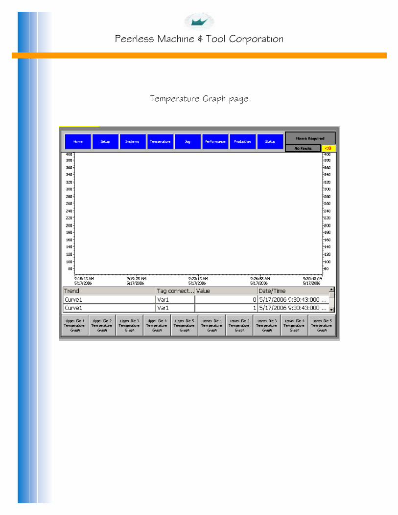
Name: Temperature graph
Function: Pressing the “Temperature Graph” button displays a Touch Panel page where a graphic comparison of die setpoint and actual temperatures can be seen. Select the die positions to view with Touch Panel inputs on the “Temperature Graph” Touch Panel screen.
Name: Fault reset
Function: Press the Touch Panel “Fault Reset” button to clear any faults that have occurred and the fault cause corrected. As an example use the “Fault Reset” Touch Panel button to clear a fault recorded when the “Jam “ sensors on the stacker recognize a part jam and stop machine production. Remove the obstructing parts and press the “Fault Reset” Touch Panel button.
Peerless Machine & Tool Corporation
Temperature Graph page

Peerless Machine & Tool Corporation
Jog page
Peerless Machine & Tool Corporation
Touch Panel Jog Page
The “Fault” indicator light is Black in color reading “Fault” when any type of fault has occurred. (A fault is indicated until both the cutting and forming heads are in their “Home” positions). The indicator is gray in color reading “No Fault” when no fault has occurred or a Fault has been “Reset”. See “Fault Reset” instructions in this manual.
The numerical display in the upper right corner of the Touch Panel page beside the “Fault” indicator represents the current production “Program Number” selected.
The “Machine Stop Active” indicator flashes Red and Black when a “Machine Stop” button is latched in its’ depressed position. The indicator disappears all “Machine Stop” buttons are released.
Forming Section controls
Name: Home
Function: The machine must be “On” to enable the “Home” function. Refer to the “Touch Panel Systems Page” of this manual. Press the “Home” button on the Touch Panel “Manual” page to move the Forming drive actuator to its’ predetermined “Home” position calibrating the drive system for controlled actuator movements. The forming head will open slightly releasing its’ brake and then move to “Home” position. The drive system must be “Homed” each time the main electrical disconnect switch is turned “Off”. A “Home Required” indicator flashes Red and Black until both the Cutting and Forming heads are in their “Home” positions when the indicator is gray in color reading “Home Complete”. The Touch Panel directional arrows indicating forming head travel direction and actuator travel limit switches are not functional until the actuator is “Homed”.
The “Cylinder Position” display on the Touch Panel indicates actuator position. The display can be used for positional reference and confirmation the actuator is motionless. If necessary the position can be displayed in inches measure by pressing the “Display Inches” Touch Panel button.

Peerless Machine & Tool Corporation
Name: Extend
Function: The machine must be “On” to enable the “Extend” function. Refer to the “Touch Panel Systems Page” of this manual. Depressing the Forming Section manual “Extend” button causes the actuator to move in the extend direction. Releasing the button stops forming head motion. The forming head actuator “Extend” limit switch stops actuator motion at its’ travel limit. At the “Extend” travel the actuator can only be moved in the “Retract direction. Note the green directional arrow indicating forming head travel direction to determine “Extend” or “Retract” actuator movement.
The “Cylinder Position” display on the Touch Panel indicates actuator position. The display can be used for positional reference and confirmation the actuator is motionless. If necessary the position can be displayed in inches measure by pressing the “Display Inches” Touch Panel button.
Name: Retract
Function: The machine must be “On” to enable the “Retract” function Refer to the “Touch Panel Systems Page” of this manual. Depressing the Forming Section manual “Retract” button causes the actuator to move in the retract direction. Releasing the button stops forming head motion. The forming head actuator “Retract” limit switch stops actuator motion at its’ travel limit. At the “Retract” travel the actuator can only be moved in the “Extend direction. Note the green directional arrow indicating forming head travel direction to determine “Extend” or “Retract” actuator movement.
The “Cylinder Position” display on the Touch Panel indicates actuator position. The display can be used for positional reference and confirmation the actuator is motionless. If necessary the position can be displayed in inches measure by pressing the “Display Inches” Touch Panel button.

Peerless Machine & Tool Corporation
Cutting Section controls
Name: Home
Function: The machine must be “On” to enable the “Home” function. Refer to the “Touch Panel Systems Page” of this manual. Press the “Home” button on the Touch Panel “Manual” page to move the Cutting drive actuator to its’ predetermined “Home” position calibrating the drive system for controlled actuator movements. The cutting head will open slightly releasing its’ brake and then move to “Home” position. The drive system must be “Homed” each time the main electrical disconnect switch is turned “Off”. A “Home Required” indicator flashes Red and Black until both the Cutting and Forming heads are in their “Home” positions when the indicator is gray in color reading “Home Complete”. The Touch Panel directional arrows indicating forming head travel direction and actuator travel limit switches are not functional until the actuator is “Homed”.
The “Cylinder Position” display on the Touch Panel indicates actuator position. The display can be used for positional reference and confirmation the actuator is motionless. If necessary the position can be displayed in inches measure by pressing the “Display Inches” Touch Panel button.
Name: Extend
Function: The machine must be “On” to enable the “Extend” function Refer to the “Touch Panel Systems Page” of this manual. Depressing the Cutting Section manual “Extend” button causes the actuator to move in the extend direction. Releasing the button stops cutting head motion. The cutting head actuator “Extend” limit switch stops actuator motion at its’ travel limit. At the “Extend” travel the actuator can only be moved in the “Retract direction. Note the green directional arrow indicating cutting head travel direction to determine “Extend” or “Retract” actuator movement.
The “Cylinder Position” display on the Touch Panel indicates actuator position. The display can be used for positional reference and confirmation the actuator is motionless. If necessary the position can be displayed in inches measure by pressing the “Display Inches” Touch Panel button.

Peerless Machine & Tool Corporation
Name: Retract
Function: The machine must be “On” to enable the “Retract” function Refer to the “Touch Panel Systems Page” of this manual. Depressing the Cutting Section manual “Retract” button causes the actuator to move in the retract direction. Releasing the button stops cutting head motion. The cutting head actuator “Retract” limit switch stops actuator motion at its’ travel limit. At the “Retract” travel the actuator can only be moved in the “Extend direction. Note the green directional arrow indicating cutting head travel direction to determine “Extend” or “Retract” actuator movement.
The “Cylinder Position” display on the Touch Panel indicates actuator position. The display can be used for positional reference and confirmation the actuator is motionless. If necessary the position can be displayed in inches measure by pressing the “Display Inches” Touch Panel button.
Name: Manual override
Function: The “Manual Override” function is only used in unusual circumstances when a paper jam occurs, the electrical disconnect switch is turned “Off” to attempt clearing the jam, the jam cannot be cleared, and the actuator cannot move to “Home” position when commanded to. The “Manual Override” function is password protected to limit its’ use. Press the “Manual Override” Touch Panel button. Enter the password. Press the “Manual Override” button a second time to access the Touch Panel “Forming Extend”, “Forming Retract”, “Cutting Extend”, and “Cutting Retract” buttons on the “Manual Override” Touch Panel page. Press the Touch Panel button to move the actuator in the direction determined necessary to open the dies to clear the paper jam. Releasing the button stops actuator travel. The actuator rod moves away from its’ housing in the “Extend” direction and into its” housing in the “Retract” direction. Open the dies just enough to clear the paper jam. Travel limit switches are not functional in “Manual Override” mode. Actuators can be severely damaged if commanded to travel past their limits. Clear the paper jam. “Home” the Cutting and Forming heads as instructed in the “Touch Panel Manual Page” “Home” instructions in this manual. A “Home Required” indicator flashes Red and Black until both the Cutting and Forming heads are in their “Home” positions when the indicator is gray in color reading “Home Complete”.
Feed Section Controls
Name: Forward
Function: The feed must be “On” to enable the feed manual “Forward” function. Refer to the “Touch Panel Systems Page” of this manual. Depressing the feed section manual “Forward” button causes the feed to move in the paper feed direction. Releasing the button stops feed roller motion.

Peerless Machine & Tool Corporation
Jog Over-Ride page

Peerless Machine & Tool Corporation
Performance page

Peerless Machine & Tool Corporation
Performance page
A “Home Required” indicator flashes Red and Black until both the Cutting and Forming heads are in their “Home” positions when the indicator is gray in color reading “Home Complete”. Refer to homing procedures in the “Manual page” instructions.
The “Fault” indicator light is Black in color reading “Fault” when any type of fault has occurred. (A fault is indicated until both the cutting and forming heads are in their “Home” positions). The indicator is gray in color reading “No Fault” when no fault has occurred or a Fault has been “Reset”. See “Fault Reset” instructions in this manual.
The numerical display in the upper right corner of the Touch Panel page beside the “Fault” indicator represents the current production “Program Number” selected.
“Product Count” is displayed in total number of parts produced. Parts produced are calculated by multiplying machine production strokes by the “Number of dies” value entered on the “Touch panel setup page”. “Product Count” is reset to zero by pressing the Touch Panel “Production reset” button.
Production rate in “Strokes per Minute” is calculated from a number of variables input on the “Touch Panel Setup Page”. Each time the “Save Profile” button on the “Touch Panel Setup Page” is depressed a production rate of “Strokes per Minute” is calculated and displayed here and on the “Touch Panel Setup Page”.
“Total Production Time” is the cumulative time the machine has been in “Production”. The timer is reset to zero by pressing the “Production Reset” button on the “Touch Panel Performance page”. “Total Production Time” is displayed here and on the “Touch Panel Production page”.
Pressing the Touch Panel “Production reset” button resets the “Product Count” and “Total Production Time” displays to zero values.

Peerless Machine & Tool Corporation
Production Start page

Peerless Machine & Tool Corporation
Touch Panel Production Start Page
Name: Fault reset
Function: Press the Touch Panel “Fault Reset” button to clear any faults that have occurred and the fault cause corrected. As an example use the “Fault Reset” Touch Panel button to clear a fault recorded when the “Jam “ sensors on the stacker recognize a part jam and stop machine production. Remove the obstructing parts and press the “Fault Reset” Touch Panel button.
The “Fault” indicator light is Black in color reading “Fault” when any type of fault has occurred. The indicator is gray in color reading “No Fault” when no fault has occurred or a Fault has been “Reset”. See “Fault Reset” instructions in this manual.
Name: Jam reset
Function: Press the Touch Panel “Jam Reset” button to reset the “Jam” counters to zero. The machine will not operate in “Production” mode until jam counters are reset.
Name: Stacker reset
Function: Press the Touch Panel “Stacker Reset” button to reset the “Drop” and “Stack” counters to zero discharging any accumulated parts in the stacker “cans”.
Name: Top die air on
Function: Press the “Top Die Air On” Touch Panel button to enable the “Top Die Air” valve. Refer to the “Touch Panel Setup page” instructions in this manual for timing procedures.
Name: Top die air off
Function: Press the “Top Die Air Off” Touch Panel button to disable the “Top Die Air” valve. Refer to the “Touch Panel Setup page” instructions in this manual for timing procedures.
Name: Bottom die air on
Function: Press the “Bottom Die Air On” Touch Panel button to enable the “Bottom Die Air” valve. Refer to the “Touch Panel Setup page” instructions in this manual for timing procedures.

Peerless Machine & Tool Corporation
Name: Bottom die air off Function: Press the “Bottom Die Air Off” Touch Panel button to disable the “Bottom Die Air” valve. Refer to the “Touch Panel Setup page” instructions in this manual for timing procedures. Name: Tray assist air on Function: Press the “Tray Assist Air On” Touch Panel button to enable the “Tray Assist Air” valve. Refer to the “Touch Panel Setup page” instructions in this manual for timing procedures. Name: Tray assist air off Function: Press the “Tray Assist Air Off” Touch Panel button to disable the “Tray Assist Air” valve. Refer to the “Touch Panel Setup page” instructions in this manual for timing procedures. Name: Jam detection system on Function: Press the “Jam Detection System On” Touch Panel button to enable the “Jam Detection” sensors. Appropriate sensors were selected with the “Number of Dies” chosen in the “Touch Panel Setup page” instructions in this manual. Name: Jam detection system off Function: Press the “Jam Detection System Off” Touch Panel button to disable the “Jam Detection” sensors. Name: Registration on Function: Press the “Registration On” Touch Panel button to enable the printed paper “Registration” eye. Refer to the “Touch Panel Setup Page” instructions in this manual for “Registration” eye functions and adjustments. Name: Registration off Function: Press the “Registration Off” Touch Panel button to disable the printed paper “Registration” eye. There may be other “On – Off” Touch Panel controls for specific customer options.

Peerless Machine & Tool Corporation
Name: Go to start position Function: The “Machine” and “Feed” must be “On” for the “Go To Start Position” function. Refer to the “Touch Panel Systems Page” instructions in this manual for “Machine” and “Feed” button functions. The Cutting and Forming heads must be in their “Home” positions. A “Home Required” indicator flashes Red and Black until both the Cutting and Forming heads are in their “Home” positions when the indicator is gray in color reading “Home Complete”. Refer to the “Touch Panel Manual Page” instructions for “Homing” procedures. Press the “Go To Start Position” Touch Panel button. The “Cutting” and “Forming” head actuators will move to their production “Start” positions. The “Cutting” head “Start” position is fixed. It opens to a point allowing the paper to feed unrestricted through the open cutting die. The “Forming” head “Start” position is the “Head Open” position. “Head Open” position adjustment is described in the “Touch Panel Setup Page” instructions in this manual. Name: Production start Function: “Cutting” and “Forming” actuators must be in their “Start Positions”. The “Jam Detection” system must be ”Reset”. The “Feed “ and “Stacker” must be “On”. Refer to the “Touch Panel Systems Page” instructions in this manual for “Feed” and “Stacker” button functions. Other functions as die “Heat”, “Top Die Air”, “Bottom Die Air”, Tray Assist Air”, and “Jam Detection”, and “Registration” may be “On”. Refer to the Touch Panel “Temperature”, “Systems” and “Production” pages instructions of this manual for their functions. All “Machine Stop” buttons must be released. The “Machine Stop Active” indicator flashes Red and Black when a “Machine Stop” button is latched in its’ depressed position. The indicator disappears all “Machine Stop” buttons are released. When all conditions are satisfied the Touch Panel “Production Start” button will appear. Press and hold the “Production Start” Touch Panel button depressed until machine begins motion. Release the “Production Start” Touch Panel button. The machine will cycle continuously until motion is stopped by a problem sensed by the “Jam Detection” system, an actuator controller fault, or pressing a “Machine Stop” or “Emergency Stop” button. The “Fault” indicator light is Black in color reading “Fault” when any type of fault has occurred. (A fault is indicated until both the cutting and forming heads are in their “Home” positions). The indicator is gray in color reading “No Fault” when no fault has occurred or a Fault has been “Reset”. See “Fault Reset” instructions in this manual. The numerical display in the upper right corner of the Touch Panel page beside the “Fault” indicator represents the current production “Program Number” selected. “Total Production Time” is the cumulative time the machine has been in “Production”. The timer is reset to zero by pressing the “Production Reset” button on the “Touch Panel Performance page”. “Total Production Time” is displayed here and on the “Touch Panel Performance page”.

Peerless Machine & Tool Corporation
Status page

Peerless Machine & Tool Corporation
Status page
Press the “Status” Touch Panel screen choice to view the “Status” page. Screen choices of “More status” for “Status 2” page and “Faults” for the Touch Panel “Fault” page are available on the “Status” page. “Fault” and “Status” pages are meant as a diagnostic aid when the machine does not respond appropriately to commands on conditions. A positive fault / status indicator light should direct a technician to likely problem causes. A “Home Required” indicator flashes Red and Black until both the Cutting and Forming heads are in their “Home” positions when the indicator is gray in color reading “Home Complete”. Refer to homing procedures in the “Manual page” instructions. The “Fault” indicator light is Black in color reading “Fault” when any type of fault has occurred. (A fault is indicated until both the cutting and forming heads are in their “Home” positions). The indicator is gray in color reading “No Fault” when no fault has occurred or a Fault has been “Reset”. See “Fault Reset” instructions in this manual. The numerical display in the upper right corner of the Touch Panel page beside the “Fault” indicator represents the current production “Program Number” selected.
Press the Touch Panel “Fault Reset” button to clear any faults that have occurred and the fault cause corrected. As an example use the “Fault Reset” Touch Panel button to clear a fault recorded when the “Jam “ sensors on the stacker recognize a part jam and stop machine production. Remove the obstructing parts and press the “Fault Reset” Touch Panel button.

Peerless Machine & Tool Corporation
Status list
Master relay 1
A green status light indicates the Master Relay is in its’ closed condition. Master relay 1 has to be closed to operate the machine.
A red status light indicates Master Relay is in its’ open condition. The machine will not operate with Master Relay 1 open.
An Emergency Stop button may be depressed.
Release all Emergency Stop buttons.
The Stacker cable connecting to the left side of the machine may be disconnected.
Insert the stacker cord plug into its’ receptacle and latch the plug securely.
Replace faulty relay.
Master relay 2
A green status light indicates all machine guards are locked and the Master Relay is in its’ closed condition. Master relay 2 has to be closed to operate the machine.
A red status light indicates the Master Relay is in its’ open condition. The machine will not operate with Master Relay 2 open.
One or more machine guards are open.
Refer to individual guard status lights to determine which guard(s) is (are) open.
Close open guards. “Lock” machine guards.
Replace faulty relay.

Peerless Machine & Tool Corporation
Master relay 3
A green status light indicates all feed guards are locked and the Master Relay is in its’ closed condition. Master relay 3 has to be closed to operate the machine.
A red status light indicates the Master Relay is in its’ open condition. The machine will not operate with Master Relay 3 open.
One or more feed guards are open.
Refer to individual guard status lights to determine which guard(s) is (are) open.
Close open guards. “Lock” feed guards.
Replace faulty relay.
Cutting guard – A
Cutting guard – A covers the end of the cutting head on the operator (right) side of the machine.
A green status light indicates the guard is closed and locked.
A red status light indicates the guard is open and / or unlocked. The machine will not operate with a guard open.
Close the guard door. “Lock” machine guards.
Replace faulty switch.
Blank chute guard – A
Blank chute guard – A covers the area between the cutting and forming sections of the machine on the operator (right) side.
A green status light indicates the guard is closed and locked.
A red status light indicates the guard is open and / or unlocked. The machine will not operate with a guard open.
Close the guard door. “Lock” machine guards.
Replace faulty switch.

Peerless Machine & Tool Corporation
Scrap guard – A
The scrap guard covers the end of the paper scrap cutter on the operator (right) side of the machine.
A green status light indicates the guard is closed and locked.
A red status light indicates the guard is open and / or unlocked. The machine will not operate with a guard open.
Close the guard door. “Lock” feed guards.
Replace faulty switch. Blank chute guard – A
Blank chute guard – A covers the area between the cutting and forming sections of the machine on the operator (right) side.
A green status light indicates the guard is closed and locked.
A red status light indicates the guard is open and / or unlocked. The machine will not operate with a guard open.
Close the guard door. “Lock” machine guards.
Replace faulty switch.
Forming guard – A
Forming guard – A covers the end of the forming head on the operator (right) side of the machine.
A green status light indicates the guard is closed and locked.
A red status light indicates the guard is open and / or unlocked. The machine will not operate with a guard open.
Close the guard door. “Lock” machine guards.
Replace faulty switch.
Peerless Machine & Tool Corporation
Forming guard – B
Forming guard – B covers the end of the forming head on the opposite operator (left) side of the machine.
A green status light indicates the guard is closed and locked.
A red status light indicates the guard is open and / or unlocked. The machine will not operate with a guard open.
Close the guard door. “Lock” machine guards.
Replace faulty switch.
Forming head block limit switch
The forming head “Stop” block rests in a limit switch on the machine sideframe.
A green status light indicates the “Stop” block is correctly inserted in its’ switch.
A red status light indicates the “Stop” block is removed from, or incorrectly inserted into, its’ switch. The machine will not operate until the “stop” block is correctly inserted in its’ switch.
Correctly insert the stop block in its’ switch.
Replace faulty switch. Cutting head block limit switch
The cutting head “Stop” block rests in a limit switch on the machine sideframe.
A green status light indicates the “Stop” block is correctly inserted in its’ switch.
A red status light indicates the “Stop” block is removed from, or incorrectly inserted into, its’ switch. The machine will not operate until the “stop” block is correctly inserted in its’ switch.
Correctly insert the stop block in its’ switch.
Replace faulty switch.
Peerless Machine & Tool Corporation
Air pressure OK
A pressure switch at the machine air pressure supply inlet monitors air pressure to the machine.
A green status light indicates sufficient air pressure to operate the machine.
A red status light indicates insufficient air pressure to operate the machine. The cutting and forming head brakes RELEASE with air pressure to allow the machine to operate. The machine will not operate with insufficient air pressure.
Insure there is a constant 80 P.S.I. (5.5 bar) air supply to the machine pneumatic system.
Registration enable Photo eye
The photo registration eye must be turned “On” to monitor its’ function.
The status light flashes green each time the photo eye recognizes a printed registration mark.
The status light remains gray if no registration mark is sensed.
Adjust the photo eye per its’ operating instructions.
Grease pump enable
The grease pump is functional when the “Feed” is “On”.
A gray status light indicates there is no electrical control signal to the pump.
A green status light indicates the pump electrical control signal is “On”..
Insure “Feed” is “On”.
Refer to machine electrical drawings to diagnose problem.

Peerless Machine & Tool Corporation
Roll stand setup enable
A green status light indicates the “Roll Stand Set Up On” Touch Panel button has been depressed. The machine will not operate with the “Roll Stand Set Up On” Touch Panel button depressed.
Press the “Roll Stand Set Up Off” Touch Panel button.
Forming retract OT PRX
The forming retract over travel limit switch senses the forming actuator is out of its’ normal travel range in the retract direction.
A green status light indicates the actuator is in its’ normal operating range. The machine will not operate when the actuator is out of its’ normal operating range.
Contact the Peerless Service Department with any problems.
Forming extend OT PRX
The forming extend over travel limit switch senses the forming actuator is out of its’ normal travel range in the extend direction.
A green status light indicates the actuator is in its’ normal operating range. The machine will not operate when the actuator is out of its’ normal operating range.
Contact the Peerless Service Department with any problems.
Forming home PRX
The “Forming home PRX” status indicates the forming head control system sensed the proximity switch during the “Homing” procedure. It is not an indication of the machine being in the “Home” position. Refer to “Homing” procedures on the “Touch Panel Systems page” instructions in this manual.
A gray status light indicates the “Forming Home Proximity switch” was sensed as the actuator reached its’ “Home” position.
When the actuator is moved from “Home” position the status light turns green and remains green until the actuator is again “Homed”.
Peerless Machine & Tool Corporation
Forming brake PRX
The forming brake proximity switch senses the brake condition.
A gray status light indicates the brake is engaged.
A green status light indicates the brake is released. Brakes must be released to operate the machine.
Verify adequate inlet supply air pressure.
Forming actuator position PE
The forming actuator position photo eye senses the forming head travel direction relative to forming actuator travel direction.
A gray status light indicates the forming head is traveling downward as the actuator extends and upward as the actuator retracts.
A green status light indicates the forming head is traveling upward as the actuator extends and downward as the actuator retracts.
The Green arrows on the “Touch Panel Manual page” screen indicate head direction.
Cutting retract OT PRX
The cutting retract over travel limit switch senses the cutting actuator is out of its’ normal travel range in the retract direction.
A green status light indicates the actuator is in its’ normal operating range. The machine will not operate when the actuator is out of its’ normal operating range.
Contact the Peerless Service Department with any problems.

Peerless Machine & Tool Corporation
Cutting extend OT PRX
The cutting extend over travel limit switch senses the cutting actuator is out of its’ normal travel range in the extend direction.
A green status light indicates the actuator is in its’ normal operating range. The machine will not operate when the actuator is out of its’ normal operating range.
Contact the Peerless Service Department with any problems.
Cutting home PRX
The “Cutting home PRX” status indicates the cutting head control system sensed the proximity switch during the “Homing” procedure. It is not an indication of the machine being in the “Home” position. Refer to “Homing” procedures on the “Touch Panel Systems page instructions in this manual.
A gray status light indicates the “Cutting Home Proximity switch” was sensed as the actuator reached its’ “Home” position.
When the actuator is moved from “Home” position the status light turns green and remains green until the actuator is again “Homed”.
Cutting brake PRX
The cutting brake proximity switch senses the brake condition.
A gray status light indicates the brake is engaged.
A green status light indicates the brake is released. Brakes must be released to operate the machine.
Verify adequate inlet supply air pressure.

Peerless Machine & Tool Corporation
Cutting actuator position PE
The cutting actuator position photo eye senses the forming head travel direction relative to cutting actuator travel direction.
A gray status light indicates the cutting head is traveling downward as the actuator extends and upward as the actuator retracts.
A green status light indicates the cutting head is traveling upward as the actuator extends and downward as the actuator retracts.
The Green arrows on the “Touch Panel Manual page” screen indicate head direction.
Machine guards unlatch
A gray status light indicates the “Machine Guard Lock” button on the “Touch Panel Systems page” has been pressed.
A red status light indicates the “Machine Guard Unlock” button on the “Touch Panel Systems page” has been pressed. The machine will not operate when machine guards are “Unlocked”.
Machine setup ready
The ”Machine setup” system is normally used in the forming die alignment process. Refer to the “Setup system” instructions in this manual for proper use. The Stacker is removed when using “Setup system” controls.
A gray status light indicates the “Set up” system key switch on the operator console is “Off”.
A green status light indicates the “Set up” system key switch on the operator console is “On”
.

Peerless Machine & Tool Corporation
Machine setup enable
The ”Machine setup” system is normally used in the forming die alignment process. Refer to the “Setup system” instructions in this manual for proper use. The Stacker is removed when using “Setup system” controls.
A gray status light indicates the “Set up” system on the “Touch Panel Systems page” is “Off”.
A green status light indicates the “Set up” system on the “Touch Panel Systems page” is “On”.
Machine setup mode
The ”Machine setup” system is normally used in the forming die alignment process. Refer to the “Setup system” instructions in this manual for proper use. The Stacker is removed when using “Setup system” controls.
A gray status light indicates the “Set up” system directional controls are not being used.
A green status light indicates the “Set up” system directional controls are being used.
Feed guards unlatch
A gray status light indicates the “Feed Guard Lock” button on the “Touch Panel Systems page” has been pressed.
A red status light indicates the “Feed Guard Unlock” button on the “Touch Panel Systems page” has been pressed. The machine will not operate when machine guards are “Unlocked”.
.

Peerless Machine & Tool Corporation
Status 2 page

Peerless Machine & Tool Corporation
Status 2 page
“Fault” and “Status” pages are meant as a diagnostic aid when the machine does not respond appropriately to commands on conditions. A positive fault / status indicator light should direct a technician to likely problem causes.
A “Home Required” indicator flashes Red and Black until both the Cutting and Forming heads are in their “Home” positions when the indicator is gray in color reading “Home Complete”. Refer to homing procedures in the “Manual page” instructions.
The “Fault” indicator light is Black in color reading “Fault” when any type of fault has occurred. (A fault is indicated until both the cutting and forming heads are in their “Home” positions). The indicator is gray in color reading “No Fault” when no fault has occurred or a Fault has been “Reset”. See “Fault Reset” instructions in this manual.
The numerical display in the upper right corner of the Touch Panel page beside the “Fault” indicator represents the current production “Program Number” selected.
Press the Touch Panel “Fault Reset” button to clear any faults that have occurred and the fault cause corrected. As an example use the “Fault Reset” Touch Panel button to clear a fault ecorded when the “Jam “ sensors on the stacker recognize a part jam and stop machine production. Remove the obstructing parts and press the “Fault Reset” Touch Panel button.
Estop pushed operator
A gray status light indicates the “E-Stop” push button on the operator Touch Panel enclosure has not been depressed.
A red status light indicates the “E-Stop” push button on the operator Touch Panel enclosure is depressed. The machine will not operate with an “E-stop” button depressed.
Release the “E-Stop” button.
Estop pushed P3
A gray status light indicates the “E-Stop” push button on the machine left side electrical enclosure has not been depressed.
A red status light indicates the “E-Stop” push button on the machine left side electrical enclosure is depressed. The machine will not operate with an “E-stop” button depressed.
Release the E-Stop” button.

Peerless Machine & Tool Corporation
Estop pushed roll stand
A gray status light indicates the “E-Stop” push button on the roll stand has not been depressed.
A red status light indicates the “E-Stop” push button on the roll stand is depressed. The machine will not operate with an “E-stop” button depressed.
Release the “E-Stop” button.
Estop pushed stacker
A gray status light indicates the “E-Stop” push button on the stacker has not been depressed.
A red status light indicates the “E-Stop” push button on the stacker is depressed. The machine will not operate with an “E-stop” button depressed.
Release the “E-Stop” button.
Jam fault detected
A gray status light indicates a part jam has not been detected. A red status light indicates a part jam has been detected.
After clearing the jam the system can be reset with any “Fault” or “Jam Reset” Touch Panel push button.
Jam sensors 1 – 5
The “Jam Sensors” status indicates the Jam System proximity switch sensed a passing part. Production lanes 1 (machine left side)-5 (machine right side) have individual sensors positioned to detect passing parts. See “Jam Detection “ system instructions in the “Production Touch Panel page” instructions of this manual.
The indicator flashes gray when a part is sensed.
All other times the indicator is green.

Peerless Machine & Tool Corporation
Cutting drive ready
A red status light indicates there is no electrical input power to the cutting drive motion controller or an E-Stop button is depressed.
Refer to machine electrical drawings to diagnose problem.
Observe E-Stop buttons status. Release all depressed E-Stop buttons.
Cutting shunt overtemp
A green status light indicates the “Shunt: resistor is in normal operating range.
A red status light indicates electrical input power is “off”.
Contact the Peerless Service Department with any problems.
Feed drive ready
A red status light indicates there is no electrical input power to the feed drive motion controller or an E-Stop button is depressed.
Refer to machine electrical drawings to diagnose problem.
Observe E-Stop buttons status. Release all depressed E-Stop buttons.
Form drive ready
A red status light indicates there is no electrical input power to the forming drive motion controller or an E-Stop button is depressed.
Refer to machine electrical drawings to diagnose problem.
Observe E-Stop buttons status. Release all depressed E-Stop buttons.
Form shunt overtemp
A green status light indicates the “Shunt: resistor is in normal operating range.
A red status light indicates electrical input power is “off”.
Contact the Peerless Service Department with any problems.

Peerless Machine & Tool Corporation
Pull roll sensors
A green status light indicates the roll stand “Pull rollers” are closed.
A red status light indicates the roll stand “Pull rollers” are open. The paper fees system will not operate with the rollers “open”.
Select the appropriate “Pull roller” position with the “Pull roller” manual air switch on the roll stand.
Stacker counter photoeye
The “Stacker Counter Photoeye” status indicates the Counter proximity switch sensed a passing part. The same sensor is used for the “Stacker counter” and “Jam Sensor” lane 1 (machine left side).
The indicator flashes gray when a part is sensed.
All other times the indicator is green.
Short circuit indicator out 1 – 8
A gray status light indicates there is no problem.
Contact the Peerless Service Department if the status indicator changes.
Short circuit indicator out 9 – 16
A gray status light indicates there is no problem.
Contact the Peerless Service Department if the status indicator changes.
Safety relay (SR2) A gray status light indicates there is no problem.
Contact the Peerless Service Department if the status indicator changes.
Peerless Machine & Tool Corporation
Cutting axis estop active
A gray status light indicates the “Cutting axis” is operational.
A red status light indicates electrical input power is “off”.
Contact the Peerless Service Department with any problems.
Cutting axis control stop active A gray status indicator indicates there is no problem.
Contact the Peerless Service Department if the status indicator changes.
Forming axis estop active
A gray status light indicates the “Forming axis” is operational.
A red status light indicates electrical input power is “off”.
Contact the Peerless Service Department with any problems.
Forming axis control stop active A gray status indicator indicates there is no problem.
Contact the Peerless Service Department if the status indicator changes.
Feed axis estop active
A gray status light indicates the “Feed axis” is operational.
A red status light indicates electrical input power is “off”.
Contact the Peerless Service Department with any problems.
Feed axis control stop active A gray status light indicates there is no problem.
Contact the Peerless Service Department if the status indicator changes.

Peerless Machine & Tool Corporation
Machine stop active
A gray status light indicates no Machine Stop push buttons are depressed.
A red status light indicates a “Stop” button is depressed. The machine will not operate with a Machine Stop button depressed.
Release the “Stop” button(s).

Peerless Machine & Tool Corporation
Fault page

Peerless Machine & Tool Corporation
Fault page
Press the “Status” Touch Panel screen choice to view the “Status” page. Screen choices of “More status” for “Status 2” page and “Faults” for the Touch Panel “Fault” page are available on the “Status” page. “Fault” and “Status” pages are meant as a diagnostic aid when the machine does not respond appropriately to commands on conditions. A positive fault / status indicator light should direct a technician to likely problem causes. A “Home Required” indicator flashes Red and Black until both the Cutting and Forming heads are in their “Home” positions when the indicator is gray in color reading “Home Complete”. Refer to homing procedures in the “Manual page” instructions. The “Fault” indicator light is Black in color reading “Fault” when any type of fault has occurred. (A fault is indicated until both the cutting and forming heads are in their “Home” positions). The indicator is gray in color reading “No Fault” when no fault has occurred or a Fault has been “Reset”. See “Fault Reset” instructions in this manual. The numerical display in the upper right corner of the Touch Panel page beside the “Fault” indicator represents the current production “Program Number” selected. Press the Touch Panel “Fault Reset” button to clear any faults that have occurred and the fault cause corrected. As an example use the “Fault Reset” Touch Panel button to clear a fault recorded when the “Jam “ sensors on the stacker recognize a part jam and stop machine production. Remove the obstructing parts and press the “Fault Reset” Touch Panel button.
Fault list
“Upper / Lower die overtemp” faults 1 through 10 indicate the “Actual” die temperature has exceeded the temperature controller “Setpoint” by more than 30 degrees and electrical power to the die heaters has been temporarily interrupted by opening the die heat relay(s).
A gray status light indicates the die temperature is in normal operating range.
A red status light indicates an over-temperature condition.
After the die(s) cool or new setpoint(s) entered with the “Setpoint” and “Actual” temperatures within 30 degrees press the “Fault Reset” button to clear the “Fault”. The die heat relay(s) will close to resume normal temperature control conditions.

Peerless Machine & Tool Corporation
“Machine guard lock disabled”
A gray status light indicates the “Machine Guard Lock” Touch Panel button was pressed.
A red status light indicates “Machine Guard Unlock” Touch Panel button was pressed.
“Stacker on disabled”
A gray status light indicates the “Stacker On” Touch Panel button was pressed.
A red status light indicates “Stacker Off” Touch Panel button was pressed.
“Feed on disabled”
A gray status light indicates the “Feed On” Touch Panel button was pressed.
A red status light indicates “Feed Off” Touch Panel button was pressed.
“Machine on disabled”
A gray status light indicates the “Machine On” Touch Panel button was pressed.
A red status light indicates “Machine Off” Touch Panel button was pressed.
Peerless Machine & Tool Corporation
Additional Controls
Name: Machine stop Function: Depressing any “Machine Stop” button will cause cutting and forming head motions to stop at their “Head Open” positions. Feed motion will stop after its’ completed cycle. The “Machine Stop” button must be manually released before re-starting the machine. Name: Emergency Stop Function: Depressing any emergency stop button with the machine in production immediately turns the pull roller, feed, stacker, and scrap cutter motors off and stops cutting and forming head motions. When the motors stop the head brakes are engaged and both motors turned off. The Emergency Stop button must be manually released before re-starting the machine. Name: Stacker speed Function: The “Stacker Speed” potentiometer controls stacker “conveyor” belt speed. Adjust speed to convey parts smoothly into the stacker “cans”. Name: Machine setup Off / On Function: Turning the key operated “Machine Setup” switch is one step in the procedure of changing from “Production” to “Setup” mode. Refer to “Setup System” operating instructions in this manual.

Peerless Machine & Tool Corporation
Roll Stand “Paper Roll Raise” and “Paper Roll Lower” push button electrical controls are enabled by depressing the “Roll Stand Setup On” button on the Touch Panel “Systems” page. “Paper Roll Raise” and “Paper Roll Lower” push button electrical controls are disabled when the “Roll Stand Setup Off” or “Production Start” buttons on the Touch Panel are depressed. Name: Paper roll raise Function: Depressing the “Paper Roll Raise” button simultaneously releases the roll stand lift motor brake and starts the lift motor in the raise direction. Releasing the button simultaneously engages the roll stand lift motor brake and stops the lift motor. Name: Paper roll lower Function: Depressing the “Paper Roll Lower” button simultaneously releases the roll stand lift motor brake and starts the lift motor in the lower direction. Releasing the button simultaneously engages the roll stand lift motor brake and stops the lift motor. Name: Machine Stop Function: Depressing any “Machine Stop” button will cause cutting and forming head motions to stop at their “Head Open” positions. Feed motion will stop after its’ completed cycle. The “Machine Stop” button must be manually released before re-starting the machine. Name: Emergency Stop Function: Depressing any emergency stop button with the machine in production immediately turns the pull roller, feed, stacker, and scrap cutter motors off and stops cutting and forming head motions. When the motors stop the head brakes are engaged and both motors turned off. The Emergency Stop button must be manually released before re-starting the machine.

Peerless Machine & Tool Corporation
M37T Machine Control Operating Procedures The “Operating Procedures” describe a number of procedures a person
will use in operating a Peerless M37T. Refer to the M37T “Operator Controls” section of this manual for operator controls locations and functions. Read and understand the “Operating Procedures” and “Operator Controls” sections of this manual before attempting to operate the M37T machine. Initial Production Procedure.
To resume production after electrical power has been turned off at the Main Electrical Disconnect Switch:
Cutting and Forming Head blocks must be in their interlocked switches. The Cutting and Forming Head blocks must be in their interlocked switches before the Machine can be turned On. There is no reaction to removing either Head Block from its’ interlocked switch when machine is in production. Turn the input electrical service disconnect switch On
Touch Panel “Home” page is displayed
Press the “Temperature” Touch Panel page button Select Forming die temperature
Press the displayed “Temperature Set Point” value for a required die position. A keypad will be displayed to allow the desired temperature selection. Press the number keys and “Enter” to choose the forming die temperature. Repeat the temperature selection process for all necessary forming die positions. Press the “Upper or Lower Dies” button to power the selected forming dies. The “Upper and Lower Dies” buttons toggle between Off and On when depressed. The “Number of Dies” selection will activate the appropriate die temperature controller positions when the die heat is turned On.
Peerless Machine & Tool Corporation
Close all open guards Release any depressed “Machine Stop” button Release any depressed “Emergency Stop” buttons Press the “Systems” Touch Panel page button Press “Machine Guards Lock” button Press “Feed Guards Lock” button Press “Machine On” button. The cutting and forming heads will move slightly when the machine is turned “On” releasing their “brakes”. Press “Feed On” button Press the “Manual” Touch Panel page button Press the Forming and Cutting Sections “Home” buttons. Both heads have to be in their Home positions to activate the Jog or Start Position functions. The motion warning horn sounds when the Cutting or Forming head is moving. Open the Forming head to its’ maximum Open position in the Retract direction by holding the Forming section “Retract” button depressed until motion stops. Open the Cutting Head to its’ maximum Open position in the Extend direction by holding the Cutting section “Extend” button depressed until motion stops.
The Cutting and Forming Section buttons are identified. Each section has Extend and Retract Touch Panel push buttons. As the Cutting or Forming heads move the Green and Red arrows beside the Extend and Retract push buttons exchange colors as the head passes through its closed position. The Green arrow indicates the head travel direction.

Peerless Machine & Tool Corporation
Press the “Systems” Touch Panel page button Press “Machine Off” button. The cutting and forming heads will move slightly when the machine is turned “Off” engaging their “brakes”. Press “Machine Guards Unlock” button Open the right (as viewed from the stacker end of the machine) side Cutting and Forming Die Access and Blank Chute Guard doors
PAPER THREADING AND WEB ALIGNMENT PROCESSES Turn the input electrical service disconnect switch Off Install the Cutting and Forming Head Stop Blocks between the open die shoes Remove all blanks and paper jams from cutting and forming dies and blank chutes Open the Roll Stand Pull Rollers with the air switch on the Roll Stand frame Open the Feed Idler Rollers using the air switches below the right side (as viewed from the stacker end of the machine) Cutting Die Guard Thread paper web through Roll Stand Pull Rollers and Loop Control roller Thread the paper web between the Feed Idler Rollers and Feed Drive Roller. Center the paper web in the machine width. Clamp the paper web guides fixing the paper web in the center of the machine width

Peerless Machine & Tool Corporation
Set and lock the paper decurl rollers Close Roll Stand Pull Rollers Turn the input electrical service disconnect switch On Remove the Cutting and Forming Head Stop Blocks Place both stop blocks in their interlocked switches. The Cutting and Forming Head blocks must be in their interlocked switches before the Machine can be turned On. There is no reaction to removing either Head Block from its’ interlocked switch when machine is in production. Close all open machine guards Touch Panel “Home” page is displayed Press the “Systems” Touch Panel page button Press “Feed Guard Lock” button Press “Feed On” button Press the “Manual” Touch Panel page button Advance the paper web through the Cutting and Feed roller sections using Feed Manual “Forward”, Feed Manual “Reverse”, and “Single Scrap Cut” commands. Pull Roller clutch engages to feed paper to the machine as the Loop Control roller rises. Cut paper in increments approximating feed length using the “Single Scrap Cut” command.

Peerless Machine & Tool Corporation
To access the paper Scrap Cutter area select the “Systems” page
Press the “Feed Off” button
Press the “Feed Guard Unlock” button
Open necessary feed guards
Perform necessary service
Close open Feed Guards
Press “Feed Guard Lock” button
Verify correct paper alignment. Turn the input electrical service disconnect switch Off, install the Cutting and Forming Head Stop Blocks, and Repeat the above PAPER THREADING AND WEB ALIGNMENT PROCESSES if necessary.
Press the “Systems” Touch Panel page button
Press “Machine Guards Lock” button. Press “Machine On” button. The cutting and forming heads will move slightly when the machine is turned “On” releasing their “brakes”. Press “Stacker On” button. Press the “Manual” Touch Panel page button Press the Forming and Cutting Sections “Home” buttons. Both heads have to be in their Home positions to activate the Manual or Start Position functions. The motion warning horn sounds when the Cutting or Forming head is moving. Allow the forming dies and forming head to reach operating temperature. Normally requires.30 – 45 minutes.

Peerless Machine & Tool Corporation
Move the paper web through machine using “Feed Manual Forward” and “Single Scrap Cut” commands until dried and curly paper is advanced through the Scrap Cutter. Paper from the Roll Stand to the Scrap Cutter in the machine is normally affected. The Pull Roller clutch engages to feed paper to the machine as the Loop Control roller rises. Cut paper in increments approximating feed length using the “Single Scrap Cut” command. Press the “Production” Touch Panel page button Turn “On” the required “Top Die Air”, “Bottom Die Air”, “Tray Assist Air”, “Jam Detection”, and “Registration” systems Press the “Start Position” button. Cutting and Forming heads will move to their Head Open positions and stop. The motion warning horn sounds when the Cutting or Forming head is moving. Hold the “Production Start” button depressed until the motion warning horn turns off and machine motion starts. The machine will not start if the “Production Start” button is released before motion begins. The jam detection system will be activated thirty seconds after machine motion starts. Visually monitor machine output until the jam system is activated.

Peerless Machine & Tool Corporation
Procedures to resume interrupted production
Conditions after pressing a “Machine Stop” button during production:
Depressing any “Machine Stop” button will cause cutting and forming head motions to stop at their “Head Open” positions. Feed motion will stop after its’ completed cycle. All guard switches remain locked.
Machine is On. Cutting and Forming head “Brakes” are released.
Feed is On Stacker is On Selected functions of Top Die Air, Bottom Die Air, Tray Assist Air, Jam Detection, and Registration systems remain On
Procedure to resume production after Machine Stop condition if Cutting die access is unnecessary
Release affected “Machine Stop” buttons Press the “Manual” Touch Panel page button Open the Forming head to its’ maximum Open position in the Retract direction by holding the Forming section Retract” button depressed until motion stops.

Peerless Machine & Tool Corporation
Open the Cutting Head to its’ maximum Open position in the Extend direction by holding the Cutting section “Extend” button depressed until motion stops. .
The Cutting and Forming Section buttons are identified. Each section has Extend and Retract Touch Panel push buttons. As the Cutting or Forming heads move the Green and Red arrows beside the Extend and Retract push buttons exchange colors as the head passes through its closed position. The Green arrow indicates the head travel direction.
Move the paper web through machine using “Feed Manual Forward” and “Single Scrap Cut” commands until dried and curly paper is advanced through the Scrap Cutter. Paper from the Roll Stand to the Scrap Cutter in the machine is normally affected. The Pull Roller clutch engages to feed paper to the machine as the Loop Control roller rises. Cut paper in increments approximating feed length using the Single Scrap Cut command. Press the “Systems” Touch Panel page button Press “Machine Off” button. The cutting and forming heads will move slightly when the machine is turned “Off” engaging their “brakes”. Press “Machine Guards Unlock” button Open the right (as viewed from the stacker end of the machine) side Blank Chute and Forming Die Access Guard doors Turn the input electrical service disconnect switch Off Install the Forming Head Stop Block between the open die shoes

Peerless Machine & Tool Corporation
Remove all blanks from blank chutes and forming dies Turn the input electrical service disconnect switch On
Remove the Forming Head Stop Block
Place the Forming Head Stop Block in its’ interlocked switch. The Forming Head block must be in its’ interlocked switch before the Machine can be turned On. There is no reaction to removing either Head Block from its’ interlocked switch when machine is in production. Close the Blank Chute and Forming Die Access Guard doors Touch Panel “Home” page is displayed
Press the “Systems” Touch Panel page button Press “Machine Guards Lock” button. Press “Feed Guards Lock” button Press “Machine On” button. The cutting and forming heads will move slightly when the machine is turned “On” releasing their “brakes”.
Press “Feed On” button Press “Stacker On” button Press the “Manual” Touch Panel page button Press the Forming and Cutting Sections “Home” buttons. Both heads have to be in their Home positions to activate the Manual or Start Position functions. The motion warning horn sounds when the Cutting or Forming head is moving.

Peerless Machine & Tool Corporation
Press the “Production” Touch Panel page button Turn “On” the required “Top Die Air”, “Bottom Die Air”, “Tray Assist Air”, “Jam Detection”, and “Registration” systems Press the “Start Position” button. Cutting and Forming heads will move to their Head Open positions and stop. The motion warning horn sounds when the Cutting or Forming head is moving. Hold the “Production Start” button depressed until the motion warning horn turns off and machine motion starts. The machine will not start if the “Production Start” button is released before motion begins. The jam detection system will be activated thirty seconds after machine motion starts. Visually monitor machine output until the jam system is activated.
Procedure to resume production after “Machine Stop” condition if die access is necessary
Release affected “Machine Stop” buttons Press the “Manual” Touch Panel page button Open the Forming head to its’ maximum Open position in the Retract direction by holding the Forming section “Retract” button depressed until motion stops. Open the Cutting Head to its’ maximum Open position in the Extend direction by holding the Cutting section “Extend” button depressed until motion stops.
The Cutting and Forming Section buttons are identified. Each section has Extend and Retract Touch Panel push buttons. As the Cutting or Forming heads move the Green and Red arrows beside the Extend and Retract push buttons exchange colors as the head passes through its closed position. The Green arrow indicates the head travel direction.

Peerless Machine & Tool Corporation
Press the “Systems” Touch Panel page button Press “Machine Off” button. The cutting and forming heads will move slightly when the machine is turned “Off” engaging their “brakes”. Press “Machine Guards Unlock” button Open all necessary machine guards
PAPER THREADING AND WEB ALIGNMENT PROCESSES Turn the input electrical service disconnect switch Off Install the Cutting and Forming Head Stop Blocks between the open die shoes Remove all blanks and paper jams from cutting and forming dies and blank chutes Open the Roll Stand Pull Rollers with the air switch on the Roll Stand frame Open the Feed Idler Rollers using the air switches below the right side (as viewed from the stacker end of the machine) Cutting Die Guard Thread paper web through Roll Stand Pull Rollers and Loop Control roller Thread the paper web between the Feed Idler Rollers and Feed Drive Roller. Center the paper web in the machine width. Clamp the paper web guides fixing the paper web in the center of the machine width Set and lock the paper decurl rollers Close Roll Stand Pull Rollers Turn the input electrical service disconnect switch On

Peerless Machine & Tool Corporation
Remove the Cutting and Forming Head Stop Blocks Place both stop blocks in their interlocked switches. The Cutting and Forming Head blocks must be in their interlocked switches before the Machine can be turned On. There is no reaction to removing either Head Block from its’ interlocked switch when machine is in production. Close all open machine guards Touch Panel “Home” page is displayed Press the “Systems” Touch Panel page button Press “Feed Guard Lock” button Press “Feed On” button Press the “Manual” Touch Panel page button Advance the paper web through the Cutting and Feed roller sections using Feed Manual “Forward”, Feed Manual “Reverse”, and “Single Scrap Cut” commands. Pull Roller clutch engages to feed paper to the machine as the Loop Control roller rises. Cut paper in increments approximating feed length using the “Single Scrap Cut” command.
To access the paper Scrap Cutter area select the “Systems” page
Press the “Feed Off” button
Press the “Feed Guard Unlock” button
Open necessary feed guards

Peerless Machine & Tool Corporation
Perform necessary service
Close open Feed Guards
Press “Feed Guard Lock” button
Verify correct paper alignment. Turn the input electrical service disconnect switch Off, install the Cutting and Forming Head Stop Blocks, and Repeat the above PAPER THREADING AND WEB ALIGNMENT PROCESSES if necessary. Press the “Systems” Touch Panel page button Press “Machine Guards Lock” button. Press “Machine On” button. The cutting and forming heads will move slightly when the machine is turned “On” releasing their “brakes”. Press “Stacker On” button Press the “Manual” Touch Panel page button Press the Forming and Cutting Sections “Home” buttons. Both heads have to be in their Home positions to activate the Manual or Start Position functions. The motion warning horn sounds when the Cutting or Forming head is moving.
Move the paper web through machine using “Feed Manual Forward” and “Single Scrap Cut” commands until dried and curly paper is advanced through the Scrap Cutter. Paper from the Roll Stand to the Scrap Cutter in the machine is normally affected. The Pull Roller clutch engages to feed paper to the machine as the Loop Control roller rises. Cut paper in increments approximating feed length using the Single Scrap Cut command.

Peerless Machine & Tool Corporation
Press The “Production” Touch Panel page button Turn “On” the required “Top Die Air”, “Bottom Die Air”, “Tray Assist Air”, “Jam Detection”, and “Registration” systems Press the “Start Position” button. Cutting and Forming heads will move to their Head Open positions and stop. The motion warning horn sounds when the Cutting or Forming head is moving. Hold the ”Production Start” button depressed until the motion warning horn turns off and machine motion starts. The machine will not start if the “Production Start” button is released before motion begins. The jam detection system will be activated thirty seconds after machine motion starts. Visually monitor machine output until the jam system is activated.
Conditions after pressing an “Emergency Stop” button during production: Depressing any “Emergency Stop” button will cause cutting and forming head, feed, and stacker motions to stop All guard switches remain locked.
Machine is Off. Cutting and Forming head “brakes” are engaged
Feed is Off Stacker is Off Selected functions of Top Die Air, Bottom Die Air, Tray Assist Air, Jam Detection, and Registration systems are Off

Peerless Machine & Tool Corporation
Press the “Systems” Touch Panel page button Press “Machine Off” button. The cutting and forming heads will move slightly when the machine is turned “Off” engaging their “brakes”. Press “Machine Guards Unlock” button Open necessary guards PAPER THREADING AND WEB ALIGNMENT PROCESSES Turn the input electrical service disconnect switch Off Install the Cutting and Forming Head Stop Blocks between the open die shoes Remove all blanks and paper jams from cutting and forming dies and blank chutes Open the Roll Stand Pull Rollers with the air switch on the Roll Stand frame Open the Feed Idler Rollers using the air switches below the right side (as viewed from the stacker end of the machine) Cutting Die Guard Thread paper web through Roll Stand Pull Rollers and Loop Control roller Thread the paper web between the Feed Idler Rollers and Feed Drive Roller. Center the paper web in the machine width. Clamp the paper web guides fixing the paper web in the center of the machine width Set and lock the paper decurl rollers Close Roll Stand Pull Rollers

Peerless Machine & Tool Corporation
Turn the input electrical service disconnect switch On Remove the Cutting and Forming Head Stop Blocks Place both stop blocks in their interlocked switches. The Cutting and Forming Head blocks must be in their interlocked switches before the Machine can be turned On. There is no reaction to removing either Head Block from its’ interlocked switch when machine is in production. Close all open guards Touch Panel “Home” page is displayed Press the “Systems” Touch Panel page button Press “Feed Guard Lock” button Press “Feed On” button Press the “Manual” Touch Panel page button Advance the paper web through the Cutting and Feed roller sections using Feed Manual “Forward”, Feed Manual “Reverse”, and “Single Scrap Cut” commands. Pull Roller clutch engages to feed paper to the machine as the Loop Control roller rises. Cut paper in increments approximating feed length using the “Single Scrap Cut” command.

Peerless Machine & Tool Corporation
To access the paper Scrap Cutter area select the “Systems” page
Press the “Feed Off” button
Press the “Feed Guard Unlock” button
Open necessary feed guards
Perform necessary service
Close open Feed Guards
Press “Feed Guard Lock” button
Verify correct paper alignment. Turn the input electrical service disconnect switch Off, install the Cutting and Forming Head Stop Blocks, and Repeat the above PAPER THREADING AND WEB ALIGNMENT PROCESSES if necessary Press the “Systems” Touch Panel page button Press “Machine Guards Lock” button. Press “Machine On” button. The cutting and forming heads will move slightly when the machine is turned “On” releasing their “brakes”.
Press “Stacker On” button Press the “Manual” Touch Panel page button Press the Forming and Cutting Sections “Home” buttons. Both heads have to be in their Home positions to activate the Manual or Start Position functions. The motion warning horn sounds when the Cutting or Forming head is moving.

Peerless Machine & Tool Corporation
Move the paper web through machine using “Feed Manual Forward” and “Single Scrap Cut” commands until dried and curly paper is advanced through the Scrap Cutter. Paper from the Roll Stand to the Scrap Cutter in the machine is normally affected. The Pull Roller clutch engages to feed paper to the machine as the Loop Control roller rises. Cut paper in increments approximating feed length using the Single Scrap Cut command. Press The “Production” Touch Panel page button Turn “On” the required “Top Die Air”, “Bottom Die Air”, “Tray Assist Air”, “Jam Detection”, and “Registration” systems Press the “Start Position” button. Cutting and Forming heads will move to their Head Open positions and stop. The motion warning horn sounds when the Cutting or Forming head is moving. Hold the ”Production Start” button depressed until the motion warning horn turns off and machine motion starts. The machine will not start if the “Production Start” button is released before motion begins. The jam detection system will be activated thirty seconds after machine motion starts. Visually monitor machine output until the jam system is activated.
Peerless Machine & Tool Corporation
Conditions after a Servo Motor Drive faults in Production or Manual modes:
When either the Cutting or Forming head Servo Motor Drive faults both are immediately disabled. Cutting and Forming head brakes engage stopping both heads motion. All guard switches remain locked.
Machine is Off. Cutting and Forming head “brakes” are engaged
Feed is On Stacker is On Selected functions of Top Die Air, Bottom Die Air, Tray Assist Air, Jam Detection, and Registration systems are On
Procedures to resume production after fault condition in Production or Manual modes:
Press the “Systems” Touch Panel page button Press “Machine On” button. The cutting and forming heads will move slightly when the machine is turned “On” releasing their “brakes”.
Press the “Manual” Touch Panel page button Open the Forming head to its’ maximum Open position in the Retract direction by holding the Forming section “Retract” button depressed until motion stops.

Peerless Machine & Tool Corporation
Open the Cutting Head to its’ maximum Open position in the Extend direction by holding the Cutting section “Extend” button depressed until motion stops. .
The Cutting and Forming Section buttons are identified. Each section has Extend and Retract Touch Panel push buttons. As the Cutting or Forming heads move the Green and Red arrows beside the Extend and Retract push buttons exchange colors as the head passes through its closed position. The Green arrow indicates the head travel direction.
Move the paper web through machine using “Feed Manual Forward” and “Single Scrap Cut” commands until dried and curly paper is advanced through the Scrap Cutter. Paper from the Roll Stand to the Scrap Cutter in the machine is normally affected. The Pull Roller clutch engages to feed paper to the machine as the Loop Control roller rises. Cut paper in increments approximating feed length using the Single Scrap Cut command. Press the “Systems” Touch Panel page button Press “Machine Off” button. The cutting and forming heads will move slightly when the machine is turned “Off” engaging their “brakes”. Press “Machine Guards Unlock” button Open the right (as viewed from the stacker end of the machine) side Blank Chute and Forming Die Access Guard doors Turn the input electrical service disconnect switch Off Install the Forming Head Stop Block between the open die shoes Remove all blanks from blank chutes and forming dies

Peerless Machine & Tool Corporation
Turn the input electrical service disconnect switch On Remove the Forming Head Stop Block Place the Forming Head Stop Block in its’ interlocked switch. The Forming Head block must be in its’ interlocked switch before the Machine can be turned On. There is no reaction to removing either Head Block from its’ interlocked switch when machine is in production. Close the Blank Chute and Forming Die Access Guard doors Touch Panel “Home” page is displayed
Press the “Systems” Touch Panel page button Press “Machine Guards Lock” button. Press “Feed Guards Lock” button Press “Machine On” button. The cutting and forming heads will move slightly when the machine is turned “On” releasing their “brakes”.
Press “Feed On” button Press “Stacker On” button Press the “Manual” Touch Panel page button Press the Forming and Cutting Sections “Home” buttons. Both heads have to be in their Home positions to activate the Jog or Start Position functions. The motion warning horn sounds when the Cutting or Forming head is moving. Press the “Production” Touch Panel page button Turn “On” the required “Top Die Air”, “Bottom Die Air”, “Tray Assist Air”, “Jam Detection”, and “Registration” systems

Peerless Machine & Tool Corporation
Press the “Start Position” button. Cutting and Forming heads will move to their Head Open positions and stop. The motion warning horn sounds when the Cutting or Forming head is moving. Hold the “Production Start” button depressed until the motion warning horn turns off and machine motion starts. The machine will not start if the “Production Start” button is released before motion begins. The jam detection system will be activated thirty seconds after machine motion starts. Visually monitor machine output until the jam system is activated.

Peerless Machine & Tool Corporation
Setup System
The “setup” system should only be used by personnel properly trained in operating the machine in “Setup” mode
The “Set-Up-System” allows the Forming Head to be open and closed during forming die servicing procedures. Dual, key operated, switches and a directional switch in an enclosure inside the operator’s forming section frame control Forming head travel. The switches are activated when the Setup system is turned On. Simultaneously turning the two key switches On causes the Forming head to open slightly releasing the Forming head brake and then travel in the selected direction. The Forming head will move until one or both switches are released or the Forming head drive actuator reaches its’ travel limit. The Forming head brake engages and Forming head drive electrical power is turned Off when one or both key switches are released. Both key switches must be released and simultaneously turned On to resume head movement.
To change from “Production” to “Setup” operation modes:
Press the “Manual” Touch Panel page button Release all “Machine Stop” buttons Release all “Emergency Stop” buttons
Open the Forming head to its’ maximum Open position in the Retract direction by holding the Forming section “Retract” button depressed until motion stops. Open the Cutting Head to its’ maximum Open position in the Extend direction by holding the Cutting section “Extend” button depressed until motion stops.

Peerless Machine & Tool Corporation
The Cutting and Forming Section buttons are identified. Each section has Extend and Retract Touch Panel push buttons. As the Cutting or Forming heads move the Green and Red arrows beside the Extend and Retract push buttons exchange colors as the head passes through its closed position. The Green arrow indicates the head travel direction.
Press the “Systems” Touch Panel page button Press “Machine Off” button Disconnect the Stacker-Counter and remove it from the machine Press the “Machine Setup On” button Turn the key operated Set-Up switch in the Touch Panel electrical enclosure “On” activating the Set-Up system controls
Setup system operation:
Select “Extend” or “Retract” with the directional control switch in the Set-Up controls enclosure inside the operator’s forming section frame. Visually observe the Forming actuator rod to determine travel direction. The actuator rod moves away from its’ housing in the “Extend” direction and into its” housing in the “Retract” direction Simultaneously turn the two key operated switches in the Set-Up controls enclosure On to move the Forming actuator in the selected direction. Forming head motion will stop when one or both key operated switches are released or the Forming cylinder reaches its’ travel limit. The motion warning horn sounds when the Forming head is moving.

Peerless Machine & Tool Corporation
Perform necessary die service
To change from “Setup” to “Production” operation modes:
Open the Forming head to its’ maximum open position in the Retract direction using the two key operated switches in the Set-Up controls enclosure. Travel limits Stop cylinder travel. The motion warning horn sounds when the Forming head is moving. Remove keys from switches in the Set-Up controls enclosure. Store appropriately
Install the Counter-Stacker and re-connect electrical and pneumatic supplies
Press the “Machine Setup Off” button
Remove key from the Touch Panel enclosure switch. Store appropriately
Follow Machine Control “Operating Procedures” to resume “Production” operation mode
Conditions after the Forming Head Servo Motor Drive faults in Set Up mode
The Forming head Servo Motor Drive faults is immediately disabled. Forming head brake engages stopping head motion. Follow “Setup system operation” instructions to resume Setup mode functions

Peerless Machine & Tool Corporation
M37T electrical controls and Touch Panel are supported by an Industrial Computer. The Computer has a separate electrical input service that is NOT interrupted when the input electrical service disconnect switch is Off. Refer to the “Procedures for turning the Controls Computer Off / On” to turn the Computer electrical power Off / On. The Computer electrical power should only be turned Off / On by properly trained personnel.
Procedure to turn the controls computer “Off”:
Follow “Operator Controls” and “Machine Control Operating Procedures” in this manual to stop machine production Press the “Manual” Touch Panel page button Follow “Operator Controls” and “Machine Control Operating Procedures” in this manual to open the forming dies 3 –5 inches (8 – 13 cm) with the actuator moving in the “Retract” direction. Positioning the forming actuator as noted is a convenience in minimizing time to “Home” the actuator. The actuator will “Home” from any position. Follow “Operator Controls” and “Machine Control Operating Procedures” in this manual to open the cutting die .5 - 1 inch (1 – 3 cm) with the actuator moving in the “Retract” direction. Positioning the cutting actuator as noted is a convenience in minimizing time to “Home” the actuator. The actuator will “Home” from any position. Press the “Systems” Touch Panel page button Press “Machine Off” button. The cutting and forming heads will move slightly when the machine is turned “Off” engaging their “brakes”. Turn selected functions of Top Die Air, Bottom Die Air, Tray Assist Air, Jam Detection, and Registration systems Off. Refer to the “Operator Controls” and “Machine Control Operating Procedures” in this manual for further instructions.

Peerless Machine & Tool Corporation
Turn the input electrical service disconnect switch Off Press the “Setup” Touch Panel page button. The “Setup” page is password protected. The correct password must be entered to open the Touch Panel “Setup” page. Press the “Exit Computer” button When the computer shut - down sequence is complete a prompt on the Touch Panel screen will acknowledge the Computer can be turned “Off” Open the enclosure housing the Operator Touch Panel
Turn the Computer Off / On switch to the Off position Close and latch the Touch Panel enclosure Procedure to turn the controls computer “On”: Open the enclosure housing the Operator Touch Panel Turn the Computer Off / On switch to the On position Close and latch the Touch Panel enclosure
Turn the input electrical service disconnect switch On after the touch panel screen appears Refer to the “Operator Controls” and “Machine Control Operating Procedures” in this manual to begin machine production

Peerless Machine & Tool Corporation
M37T PRESS PART NUMBERS

Peerless Machine & Tool Corporation
737T040101 CUT/SCORE
HEAD
737T040102 CUT/SCORE DIE SHOE
737T040104 CUT/SCORE
DIE SHOE CAP
737T040105 CUT/SCORE PIN BRACE
737T040106 CUT/SCORE HEAD CAP
737T040201 TOGGLE PIN
MOUNT
737T040202 TOGGLE PIN
CAP
737T040203 CUT/SCORE
TOGGLE
737T040204 CYLINDER TOGGLE
UNION
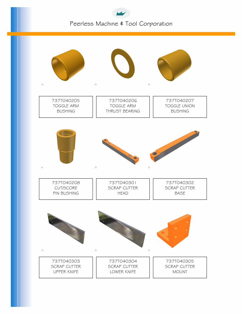
Peerless Machine & Tool Corporation
737T040205 TOGGLE ARM
BUSHING
737T040206 TOGGLE ARM
THRUST BEARING
737T040207 TOGGLE UNION
BUSHING
737T040208 CUT/SCORE
PIN BUSHING
737T040301 SCRAP CUTTER
HEAD
737T040302 SCRAP CUTTER
BASE
737T040303 SCRAP CUTTER UPPER KNIFE
737T040304 SCRAP CUTTER LOWER KNIFE
737T040305 SCRAP CUTTER
MOUNT

Peerless Machine & Tool Corporation
737T040306 HINGED SCRAP
CHUTE
737T040307 UPPER SCRAP
CHUTE
737T040311 LOWER
SCRAP CHUTE
737T040313 SCRAP CUTTER
ECCENTRIC
737T040314 SCRAP CUTTER LINK MOUNT
737T040315 SCRAP CUTTER
LINK PIN
737T040316 SCRAP CUTTER
CONNECTING LINK
737T040317 SCRAP CUTTER
SHAFT
737T040321 SCRAP CUTTER MOTOR MOUNT

Peerless Machine & Tool Corporation
737T040322 CUT/SCORE
PAPER GUIDE
737T040324 LOWER SCRAP
GUIDE
737T040325 SCRAP CUTTER
GREASE GUARD RIGHT
737T040326 SCRAP CUTTER
GREASE GUARD LEFT
737T040400 TRUNNION BUSHING
737T040401 CUT/SCORE MOUNTING
PLATE SPACER
737T040402 CUT/SCORE LOWER MOUNTING PLATE
737T040403 CUT/SCORE
HEAD SPACER
737T040404 CUT/SCORE UPPER MOUNTING PLATE

Peerless Machine & Tool Corporation
737T040501 CUT/SCORE
PIN BRACKET
737T040502 CUT/SCORE PIN
BRACKET MOUNT
737T040503 CUT/SCORE PIN BRACKET CAP
737T040701 CUT/SCORE BRAKE
BRACE
737T041001 CUT/SCORE BRAKE D MOUNT BRACKERO T
737T040901 CUT/SCORE HEAD SENSOR BRACKET
737T041002 CUT/SCORE HEAD
BRAKE SHAFT
737T041003 CUT/SCORE BRAKE
MOUNT
737T041101 SCRAP CUTTER GREASE GUARD

Peerless Machine & Tool Corporation
737T050101 BLANK CHUTE
LEFT
737T050102 BLANK CHUTE
RIGHT
737T050103 BLANK CHUTE
SUPPORT GUIDE
737T050201 BLANK CHUTE
REMOVABLE MOUNT
737T050203 BLANK CHUTE ALL- THREAD MOUNT
737T050204 BLANK CHUTE ALL-THREAD
737T050205 BLANK CHUTE
BRACE
737T050301 BLANK CHUTE MOUNT BAR
737T050302 BLANK CHUTE
MOUNT BRACKET

Peerless Machine & Tool Corporation
737T050303 BLANK STOP
CYLINDER MOUNT
737T050304 BLANK STOP
CYLINDER BAR
737T050308 LEFT SIDE UPPER
BLANK CHUTE MOUNT
737T050309 RIGHT SIDE UPPER
BLANK CHUTE MOUNT
737T050310 LEFT SIDE LOWER
BLANK CHUTE MOUNT
737T050311 RIGHT SIDE LOWER
BLANK CHUTE MOUNT
737T050312 BLANK CHUTE
MOUNTING ARM
737T050313 NEW LEFT SIDE BLANK CHUTE
737T050314 NEW RIGHT SIDE BLANK CHUTE

Peerless Machine & Tool Corporation
737T050315 BLANK CHUTE
MOUNTING CLAMP
737T050401 INCOMING PAPER
SUPPORT
737T050402 INCOMING PAPER SUPPORT MOUNT
737T050501 PRODUCT CHUTE
MOUNT
737T050502 PRODUCT CHUTE
LEFT
737T050503 PRODUCT
CHUTE RIGHT
737T050701 FORMING HEAD BRAKE BRACE
737T051001
737T060101 FORMING TOGGLE

Peerless Machine & Tool Corporation
737T060102 NITROGEN CYLINDER
FORMING BASE
737T060103 FORMING SHOE
737T060104 FORMING HEAD
737T060105 NITROGEN CYLINDER
BASE CAP
737T060106 FORMING SHOE
CAP
737T060107 FORMING HEAD
CAP
737T060109 FORMING HEAD LIGHT VERSION
737T060201 FORMING SECTION
BUSHING
737T060202 NITROGEN CYLINDER
BASE BUSHING

Peerless Machine & Tool Corporation
737T060313 FORMING HEAD BRAKE SHAFT
737T060315 FORMING HEAD BRAKE BRACKET
737T060316 FORMING HEAD
BRAKE SHAFT MOUNT
737T060317 BRAKE SHAFT
MOUNT
737T060601 FORMING SHOE
INSULATION
737T060603 UPPER DIE
MOUNTING PLATE
737T060604 DIE LOADING
ROLLER MOUNT
737T060605 BOTTOM DIE
MOUNTING PLATE
737T060606 FORMING SHOE
SPACER

Peerless Machine & Tool Corporation
737T060902 FORMING PIN BRACE CAP
737T060905 FORMING PIN
BRACE MOUNT
737T060906 FORMING PIN
BRACE
737T061001 FORMING HEAD WIRE MOUNT
737T080101 FORMNG HEAD GREASE TRAY
737T090101 DIE AIR SURGE TANK MOUNT
737T100403 CUT/SCORE HEAD CYLINDER GUARD
737T100610 FORMING GUARD
RIGHT SIDE

Peerless Machine & Tool Corporation
737T100616 CUT/SCORE
GUARD LEFT SIDE
737T100618 RIGHT SIDE SCRAP
CUTTER GUARD
737T100656 RIGHT SIDE
BLANK CHUTE GUARD
737T100659 LEFT SIDE
BLANK CHUTE GUARD
737T100664 LOWER INCOMING
GUARD
737T100672 FEED MOTOR
GUARD
737T100675 CUT/SCORE
GUARD RIGHT SIDE
737T101001 LOWER SAFETY
BAR FRAME
737T101002 SAFETY BAR
FRAME UPRIGHT
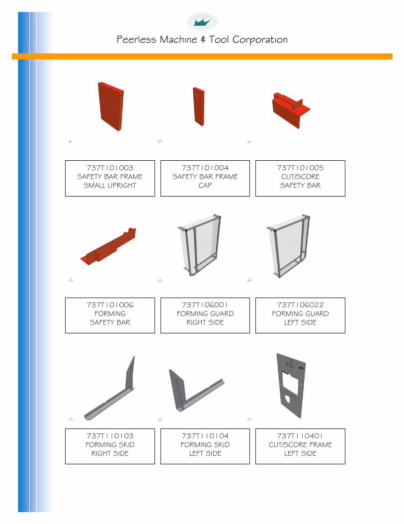
Peerless Machine & Tool Corporation
737T101003 SAFETY BAR FRAME
SMALL UPRIGHT
737T101004 SAFETY BAR FRAME
CAP
737T101005 CUT/SCORE SAFETY BAR
737T101006 FORMING
SAFETY BAR
737T106001 FORMING GUARD
RIGHT SIDE
737T106022 FORMING GUARD
LEFT SIDE
737T110103 FORMING SKID
RIGHT SIDE
737T110104 FORMING SKID
LEFT SIDE
737T110401 CUT/SCORE FRAME
LEFT SIDE

Peerless Machine & Tool Corporation
737T110402 CUT/SCORE FRAME
RIGHT SIDE
737T110404 CUT/SCORE BASE BEAM
737T110405 CUT/SCORE UPPER
TOGGLE BASE SPACER
737T110406 CUT/SCORE UPPER TOGGLE BASE TOP
737T110407 CUT/SCORE UPPER
TOGGLE BASE BOTTOM
737T110409 CUT/SCORE CYLINDER
MOUNT BEAM
737T110410 SMALL FRAME
LINK
737T110411 LARGE FRAME
LINK
737T110412 CUT/SCORE
CYLINDER MOUNT

Peerless Machine & Tool Corporation
737T110601 FORMING FRAME
RIGHT SIDE
737T110602 FORMING FRAME
LEFT SIDE
737T110603 FORMING SECTION LOWER BASE BEAM
737T110604 FORMING UPPER
BASE BEAM
737T110605 FORMING UPPER TOGGLE BASE
737T110607 FORMING CYLINDER MACHINE MOUNT
737T110612 FORMING TRUNNION
MOUNT

Peerless Machine & Tool Corporation
737T110614 FORMING TRUNNION
MOUNT CAP
737T112101 AIR VALVE
MOUNTING PLATE
737T120101 DIE LOADING
RACK
737T120102 DIE LOADING RACK
MOUNT
737T300101 WEBEX FEED
ROLLER SHAFT
737T300102 FEED ROLLER
737T300202 WEBEX FEED
ROLLER MOUNT
737T300203 FEED ROLLER CYLINDER
MOUNT
737T300204 FEED ROLLER
MOUNT

Peerless Machine & Tool Corporation
737T300301 FEED MOTOR
MOUNT
737T310101 DECURL WORM GEAR MOUNT
737T310102 DECURL FRAME
RIGHT SIDE
737T310103 DECURL FRAME
LEFT SIDE
737T310104 DECURL ADJUSTMENT
STOP
737T310201 DECURL WHEEL
SUPPORT SHAFT
737T310202 DECURL ADJUSTMENT
ARM SHAFT
737T310203 DECURL ROLLER
737T310204 DECURL ROLLER SUPPORT SHAFT

Peerless Machine & Tool Corporation
ROLLSTAND PART NUMBERS

Peerless Machine & Tool Corporation
302045 ¼- ¼ MALE CONNECTOR
302186 1/8 NPTF PRESTOLOK
MALE FITTING
302187 1/4 NPTF PRESTOLOK
MALE FITTING
302274 1/4 NPTF PRESTOLOK MALE FITTING SWIVEL
3103047 1/8 PIPE PLUG
313050 1/4 PIPE PLUG
314004 4-PORT AIR MANIFOLD
314010 6-PORT AIR MANIFOLD
322503 LEVER OPERATED
AIR VALVE

Peerless Machine & Tool Corporation
322505 ROLLER OPERATED
AIR VALVE
328009 NON-ADJUSTABLE
MUFFLER
332301 PAPER ROLLER AIR CYLINDER
341003 AIR REGULATOR
341004 AIR GUAGE
348009 AIR REGULATOR
MOUNT
481001 EYE BOLT

Peerless Machine & Tool Corporation
CA
INSID
737R020005 BACK PLATE
FR
IM
BA
FRO
737R020003 TOP UPRIGHT
SUPPORT BEAM
737R020002 LOWER MAIN CROSSBEAM
737R020001 RRIAGE SUPPORT
UPRIGHT
737R020006 ONT CROSSBEAM SUPPORT PLATE
737R020004 COMING UPRIGHT E SUPPORT PLATE
737R020009 NT WHEEL MOUNT PLATE SPACER
737R020008 CK WHEEL MOUNT PLATE SPACER
737R020007 NCOMING WHEEL OUNTING PLATE

Peerless Machine & Tool Corporation
737R020010 OUTGOING WHEEL MOUNTING PLATE
OM
F
737R020014 GEAR RACK
TM
T
737R020012 TRAVERSE CAM OLLOWER BLOCK
737R020011 UTGOING WHEEL OUNT TOP PLATE
737R020015 TRACK END
STOP
737R020013 FLOOR PLATE WELDMENT
737R020018 RAVERSE SHAFTBUSHING BLOCK737R020017 RAVERSE SHAFT OUNTING UPRIGHT
737R020016 GEAR RACK
SPACER

Peerless Machine & Tool Corporation
737R020019 TRAVERSE SHAFT
M
OSID
A
P
C
737R020022 SCREW JACK
ROD RETAINER
737R020020 OUTGOING FEED OUNTING PLATE
737R020104 BRAKE ANCHOR LATE STANDOFF
737R020101 IR CHUCK CORE
SHAFT
737R020023 UTGOING UPRIGHT E SUPPORT PLATE
737R020110 ARRIAGE FRAME SUBASSEMBLY
737R020106 ELECTRIC EYE
BRACKET
737R020105 BRAKE ANCHOR
PLATE
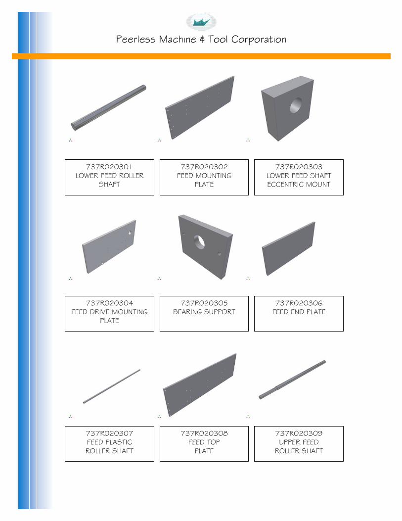
Peerless Machine & Tool Corporation
737R020301 LOWER FEED ROLLER
SHAFT
LOE
FEE
737R020305 BEARING SUPPORT
737R020303 WER FEED SHAFT
CCENTRIC MOUNT
737R020302 FEED MOUNTING
PLATE
737R020306 FEED END PLATE
737R020304 D DRIVE MOUNTING
PLATE
737R020309 UPPER FEED
ROLLER SHAFT
737R020308 FEED TOP
PLATE
737R020307 FEED PLASTIC ROLLER SHAFT

Peerless Machine & Tool Corporation
737R020310 UPPER FEED ROLLER
SHAFT SUPPORT
LOC
F
INC
OU
737R020312 WER FEED ROLLER YLINDER MOUNT
737R020311 FEED TOP PLATE SUPPORT BEAM
737R021001 MAIN GUARD
737R020314 EED DANCER ARM
SHAFT
737R020313 FEED DANCER
ARM
737R021004 INCOMING LEGGUARD
737R021003 TGOING CARRIAGE
GUARD
737R021002 OMING CARRIAGE
GUARD

Peerless Machine & Tool Corporation
737R021005 CANISTER GUARD
MOUNT
300
300WI
351006 mm AIR CHUCK WITH STOP
737R021006 UPPER FEED
ROLLER GUARD
351005 mm AIR CHUCK THOUT STOP

Peerless Machine & Tool Corporation
STACKER PART NUMBERS

Peerless Machine & Tool Corporation
332307 STACKER CAN AIR CYLINDER
B
SAIR C
STACYL
605018 ER BEARING
633001 INCLINE BELT
633020 OUTGOING BELT BE
332310 TACKER CAN YLINDER BRACE
332308 LANK STOP CYLINDER
606036 CARTRIDGE BEARING
332311 CKER CAN AIR INDER MOUNT
633021 LT SPROCKET

Peerless Machine & Tool Corporation
673001 CASTER
692761 SPROCKET GUARD
MOUNT
692762 MOTOR COVER
MOUNT
692763 MOTOR COVER
737S010101 RIGHT SIDE FRAME
737S010102 LEFT SIDE FRAME
737S010103 REAR CROSS-
SUPPORT
737S010105 RIGHT SIDE
INCLINE MOUNT
737S010106 LEFT SIDE
INCLINE MOUNT

Peerless Machine & Tool Corporation
737S010107 RIGHT SIDE LOWER
INCLINE MOUNT
737S010108 LEFT SIDE LOWER INCLINE MOUNT
737S010109 FRONT CROSS-
SUPPORT
737S010110 STACKER
STOP
737S010201 INCLINE FRAME
737S010202 LAGGING SHAFT
737S010203 INNER CROWN PULLEY SHAFT
737S010204 CROWN PULLEY
737S010205 CROWN PULLEY
SHAFT

Peerless Machine & Tool Corporation
737S010206 INCLINE LANE UPPER
SUPPORT SHAFT
737S010207 INCLINE LANE
SUPPORT BARS
737S010208 STACKER CAN SUPPORT BAR
737S010209 LEFT SIDE
LANE DIVIDER
737S010210 RIGHT SIDE
LANE DIVIDER
737S010211 INCLINE CROSS-
SUPPORT
737S010212 INCLINE SPACER
BAR
737S010213 STACKER HINGE
LEFT
737S010214 STACKER HINGE
RIGHT

Peerless Machine & Tool Corporation
737S010215 STACKER TRAY
BACK STOP
737S010301 JOGGER SHAFT
737S010302 OUTGOING STACKER
FLOOR
737S010303 IDLER SHAFT
737S010304 DRIVE SHAFT
737S010305 STACKER CAN
MOUNTING BAR
737S010307 STOP CYLINDER
MOUNT
737S010308 STOP CYLINDER MOUNT
BAR
737S010309 RIGHT STACKER CAN

Peerless Machine & Tool Corporation
737S010310 LEFT SIDE STACKER
CAN
737S010311 OUTFEED BELT SUPPORT BARS
737S010315 STACKER CAN
MOUNTING CLAMP
737S010317 OUTFEED BELT
SUPPORT
737S010318 STACKER AIRLINE
TROUGH
737S010319 RIGHT SIDE AIRLINE
CONDUIT
737S010320 LEFT SIDE AIRLINE
CONDUIT
737S010321 STACKER SHAFT
737S010701 INCLINE DRIVE
MOTOR MOUNT

Peerless Machine & Tool Corporation
737S010702 EXIT DRIVE MOTOR
MOUNT