POINTEK CLS 200 - Pacific Rim Technical Servicesprts.com.au/Support/siemens_pdf/CLS 200...
32
POINTEK CLS 200 CAPACITANCE LIQUIDS/SOLIDS Instruction Manual December 2001 POINTEK CLS 200
Transcript of POINTEK CLS 200 - Pacific Rim Technical Servicesprts.com.au/Support/siemens_pdf/CLS 200...

POINTEK CLS 200
CAPACITANCE LIQUIDS/SOLIDS
Instruction Manual December 2001
PO
INT
EK
CLS
20
0

© Siemens Milltronics Process Instruments Inc. 2001
Safety Guidelines
Warning notices must be observed to ensure personal safety as well as that of others, and toprotect the product and the connected equipment. These warning notices are accompaniedby a clarification of the level of caution to be observed.
Qualified Personnel
This device/system may only be set up and operated in conjunction with this manual.Qualified personnel are only authorized to install and operate this equipment in accordancewith established safety practices and standards.
Warning: This product can only function properly and safely if it is correctly transported,stored, installed, set up, operated, and maintained.
Note: Always use product in accordance with specifications.
Copyright Siemens Milltronics ProcessInstruments Inc. 2000. All Rights Reserved
Disclaimer of Liability
This document is available in bound version and inelectronic version. We encourage users topurchase authorized bound manuals, or to viewelectronic versions as designed and authored bySiemens Milltronics Process Instruments Inc.Siemens Milltronics Process Instruments Inc. willnot be responsible for the contents of partial orwhole reproductions of either bound or electronicversions.
While we have verified the contents ofthis manual for agreement with theinstrumentation described, variationsremain possible. Thus we cannotguarantee full agreement. Thecontents of this manual are regularlyreviewed and corrections are includedin subsequent editions. We welcomeall suggestions for improvement.
Technical data subject to change.
MILLTRONICS®is a registered trademark of Siemens Milltronics Process Instruments Inc.
Contact SMPI Technical Publications at the following address:
Technical PublicationsSiemens Milltronics Process Instruments Inc.1954 Technology Drive, P.O. Box 4225Peterborough, Ontario, Canada, K9J 7B1Email: [email protected]
For the library of SMPI instruction manuals, visit: www.siemens-milltronics.com
7ML19985AR01 Pointek CLS 200 Page 1
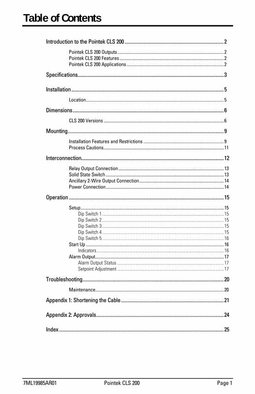
Table of Contents
Introduction to the Pointek CLS 200 ................................................................................ 2
Pointek CLS 200 Outputs......................................................................................................2 Pointek CLS 200 Features....................................................................................................2 Pointek CLS 200 Applications .............................................................................................2
Specifications...................................................................................................................... 3
Installation ........................................................................................................................... 5
Location....................................................................................................................................5
Dimensions.......................................................................................................................... 6
CLS 200 Versions ...................................................................................................................6
Mounting.............................................................................................................................. 9
Installation Features and Restrictions .............................................................................9 Process Cautions...................................................................................................................11
Interconnection................................................................................................................... 12
Relay Output Connection.....................................................................................................13 Solid State Switch .................................................................................................................13 Ancillary 2-Wire Output Connection.................................................................................14 Power Connection.................................................................................................................14
Operation ............................................................................................................................. 15
Setup.........................................................................................................................................15 Dip Switch 1 .........................................................................................................15 Dip Switch 2 .........................................................................................................15 Dip Switch 3 .........................................................................................................15 Dip Switch 4 .........................................................................................................15 Dip Switch 5 .........................................................................................................16
Start Up ....................................................................................................................................16 Indicators..............................................................................................................16
Alarm Output...........................................................................................................................17 Alarm Output Status ............................................................................................17 Setpoint Adjustment ............................................................................................17
Troubleshooting.................................................................................................................. 20
Maintenance...........................................................................................................................20
Appendix 1: Shortening the Cable ................................................................................... 21
Appendix 2: Approvals....................................................................................................... 24
Index ..................................................................................................................................... 25

Page 2 Pointek CLS 200 7ML19985AR01
Introduction to the Pointek CLS 200
Note: Pointek CLS 200 is only to be used in the manner outlined in this instruction manual.
The Pointek CLS 200 capacitance level switch provides output on high or low process material levels. When the measured material approaches or contacts the switch's probe, an increase in capacitance is sensed triggering a high level alarm. If low level monitoring is required, then the lack of material contact is sensed, triggering the low level alarm.
Pointek CLS 200 Outputs • One form C (SPDT) relay
• One open isolated, non-polarized, solid-state switch
Pointek CLS 200 Features • NPT, BSP, and 3A compliant Tri-clamp connections
(other connections on request)
• Corrosion resistant construction, Kynar®, and 316 stainless steel wetted parts
• 35m (115 ft) maximum insertion length
• Fully adjustable process alarm (level, time delay, and fail-safe mode)
• Rigid extensions of standard and sanitary versions
• Cable version with customizable length
Pointek CLS 200 Applications • Liquids, slurries, powders, granules, and solids
• Foods and pharmaceuticals
• Chemical and petrochemical
• High pressure and temperature

7ML19985AR01 Pointek CLS 200 Page 3
Specifications
Power
• 12 - 250V ac/dc • 50/60 Hz • 2 VA / 2 W max
Environmental
location: indoor/outdoor altitude: 2000m max ambient temperature: -40 to 85°C (-40 to 185°F) relative humidity: suitable for outdoor (Type 4X / NEMA 4X / IP65) installation category: II pollution degree: 4
Process
dielectric constant (εr):
1.5 min
temperature: -40 to 125°C (-40 to 257°F) pressure: standard and rigid extension versions
• 0 to 25 bar / 365 p.s.i. / 2500 kPa gauge (nominal) cable version
• 0 to 10 bar / 150 p.s.i. / 1000 kPa gauge (nominal) Alarm Output
relay: 1 form C (SPDT) contact, rated 8A at 250V ac / 5A at 30V dc, non-inductive
solid state switch: rated 250V ac / 300V dc, 100mA max (2VA max.) time delay: ON/OFF alarm selectable, 1 to 60 seconds adjustable hysterisis: 2mm (0.08") repeatability: 2mm (0.08") fail-safe operation (high or low)
Electronics/Enclosure
termination: removable terminal block, 2.5mm2 max construction: epoxy coated aluminum with gasket (optional thermal isolator, 316 stainless steel) ingress protection: Type 4X / NEMA 4X / IP65 electrical: 2 x 1/2" NPT conduit entry

Page 4 Pointek CLS 200 7ML19985AR01
Probe
Length (max)
Mounting1 Extension Tensile (max)
Sensor
Standard 5.5m (18ft) ¾ " NPT, 1" BSPT, 1 ½ BSPT 316 stainless steel
316 stainless steel
n/a Kynar®2
Sanitary 5.5m (18ft) 1", 1 ½ ", and 2"; 3A compliant tri-clamp
316 stainless steel
n/a Kynar®2
Cable 35m (115ft) ¾ " NPT, 1" BSPT, 1 ½ BSPT 316 stainless steel
Kynar®3 180kg (400 lbs)
Kynar®2
Approvals
CE, CSANRTL/C FM, CENELEC, 3A. Please verify against device nameplate.
1 Other process connections available on request. 2 Option: P.P.S. (Polyphenylen Sulfide) 3 Kynar® is a registered trademark of ELF Atochem. For a chemical resistance list for Kynar, contact your local distributor.

7ML19985AR01 Pointek CLS 200 Page 5
Installation
Location
Notes: • Installation shall only be performed by qualified personnel and in accordance with local
governing regulations. • This product is susceptible to electrostatic shock. Follow proper grounding
procedures.
The Pointek CLS 200 standard probe length is normally mounted into the vessel top (high detection alarm) or through the tank wall at the detection level (high or low detection alarm).
The extended versions are designed for top mounting. The probe suspends vertically so that it reaches into the process at the desired detection level (high or low detection alarm).
Vertical
Angle
Horizontal

Page 6 Pointek CLS 200 7ML19985AR01
Dimensions
CLS 200 Versions
Standard
Standard with Thermal Isolator
Note: * Nominal Values ** Wetted parts are Kynar®and 316 stainless steel
145mm* (5.7")
Lid Electronics/ Enclosure
120mm (4.7")
Probe/Sensor**
½" NPT
120mm (4.7")
120mm (4.7")
245mm* (9.7")
Thermal Isolator Sensor
Probe**
59mm (2.3")
76mm (3")
Lid Clip
7ML19985AR01 Pointek CLS 200 Page 7
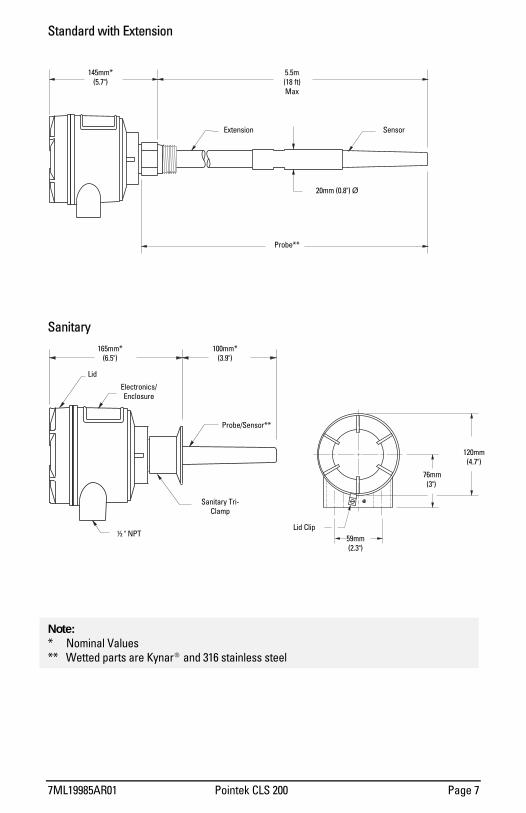
Standard with Extension
Sanitary
Note: * Nominal Values ** Wetted parts are Kynar®and 316 stainless steel
145mm* (5.7")
5.5m (18 ft) Max
20mm (0.8") Ø
Probe**
Sensor Extension
Probe/Sensor**
100mm*(3.9")
165mm* (6.5")
Lid
Sanitary Tri-Clamp
½ " NPT
Electronics/ Enclosure
120mm (4.7")
76mm (3")
59mm (2.3")
Lid Clip
Page 8 Pointek CLS 200 7ML19985AR01
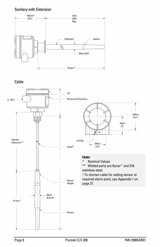
Sanitary with Extension
Cable
Note: * Nominal Values ** Wetted parts are Kynar®and 316 stainless steel. ! To shorten cable for setting sensor at required alarm point, see Appendix 1 on page 21.
165mm* (6.5")
5.5m (18ft) Max
Sensor Extension
23mm (0.9")
Lid
Electronics/Enclosure
Probe**
½ " NPT
Flexible Extension **
Cable!
Sensor Weight
Sensor
20mm (0.8") Ø
Probe**
120mm (4.7")
76mm(3")
59mm (2.3")
Lid Clip

7ML19985AR01 Pointek CLS 200 Page 9
Mounting
Installation Features and Restrictions Please note the following installation features and restrictions to ensure that your unit operates properly.
Standpipes
Multiple Units
> 100mm(4") Ø
< 50mm(2")
100mm (4") Min
100mm (4") Min
Side View
100mm (4") Min
Sensors must be 100mm apart. Mount diagonally if vertical space is restricted.
End View
Page 10 Pointek CLS 200 7ML19985AR01
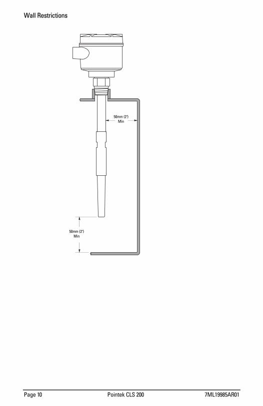
Wall Restrictions
50mm (2") Min
50mm (2") Min

7ML19985AR01 Pointek CLS 200 Page 11
Process Cautions Caution: Keep unit out of path of falling material.
Caution: Consider material surface configuration when installing unit.
Caution: Protect probe from falling material.
Caution: Tensile load must not exceed probe or vessel rating.
50mm (2") Min
Caution: Avoid areas where material build up occurs.

Page 12 Pointek CLS 200 7ML19985AR01
Interconnection
Loosen the lid clip and remove the lid to access the connectors and electronics. The identification label is on the underside of the lid.
Please note the following:
• Relay contact terminals are for use with equipment having no accessible live parts and wiring having insulation suitable for at least 250V.
• Maximum working voltage between adjacent relay contacts is 250V.
Note: Switch and potentiometer settings are for illustration purposes only.
All field wiring must have insulation suitable for at least 250V.
Max: 2VA

7ML19985AR01 Pointek CLS 200 Page 13
Relay Output Connection
The relay is shown in a de-energized state. K2 contact ratings:
• 8A at 250V ac • 5A at 30V dc
Solid State Switch
Solid state switch to customer's control or instrumentation device. Switch shown in de-energized state. K3 contact ratings:
• 250V ac, 100mA max., non-polarized (max. 2VA)
• 300V dc, 100mA max, non-polarized (max. 2VA)
Note: When driving an external relay with either the solid state switch and/or relay outputs using dc power, protection diodes must be connected in the correct polarity to prevent possible switch/relay damage resulting from inductive spikes generated by the relay coil.
Diode Protection When driving an external relay with either the solid stated switch and/or relay outputs using dc power, protection diodes must be connected in the correct polarity across the relay coil to prevent possible switch/relay damage resulting from inductive spikes generated by the relay coil.
Switch capacity: • 250V ac 100mA max.
2VA/2W max
• 300V dc. 100mA max. 2VA/2W max
relay coil
Customer supplied diode protection

Page 14 Pointek CLS 200 7ML19985AR01
Ancillary 2-Wire Output Connection
Power Connection Nominal 24 V dc 48 V dc
V dc 2226 V 4650 V
R 120 Ω 234 Ω
Optically isolated switch. (Customer supplied; we suggest Phoenix DEK-OE-5DC/48DC/100 or equivalent.)
Output
V dc (See Power Connection below)
12250 V AC/DC
(See below)
relay coil
Customer supplied diode protection

7ML19985AR01 Pointek CLS 200 Page 15
Operation
Setup
Note: Setup can be done in the field with the Pointek CLS mounted into process, or in the shop prior to mounting.
Dip Switch 1
• Set ON to open the alarm relay immediately when the sensor detects a change in contact. Use this setting when time is critical.
• Set OFF to keep the alarm relay closed by the amount set on potentiometer #1 (P1). Use
this setting when you want to slow the response to account for turbulence or false readings.
Dip Switch 2
• Set ON to open the alarm relay immediately when the sensor detects a change in contact. Use this setting when you need the alarm to stop as soon as the contact state changes.
• Set OFF to keep the alarm relay closed by the amount of time set on potentiometer #1
(P1). Use this setting when you want to avoid false or early alarm relay cut-outs due to turbulence or false readings.
Dip Switch 3
• Set ON for fail-safe high alarm. • Set OFF for fail-safe low alarm.
Dip Switch 4
• Set ON to test the delay of the alarm relays as set by the potentiometer #1 (P1). • Set OFF for normal operation.

Page 16 Pointek CLS 200 7ML19985AR01
Dip Switch 5
• Set ON for normal sensitivity on the sensor. Use this setting for measuring dry solids or non-conductive liquids.
• Set OFF for low sensitivity on the sensor. Use this setting for measuring conductive liquids or wet conductive solids that can build up.
Switches shown in OFF position.
Delay ON Delay OFF Fail Safe Delay Test Sensivity SI-1 SI-2 SI-3 SI-4 SI-5
ON disabled disabled high test normal OFF enabled enabled low normal low
Start Up After the CLS is properly mounted and the switch bank is set up, apply power to the unit. The green LED (L3) lights up to indicate the unit is powered and operational.
Indicators Three LEDs indicate the following:
L1 (yellow) = sensor status: When P2 is properly set, this LED indicates when the sensor is in contact with the process material (material capacitance is greater than the setpoint, P2).
L1 is off when the sensor is out of contact with the process material (material capacitance is less than the setpoint).
L2 (red) = output status: This LED indicates relay and solid switch contact status. Refer to Operation/Output Status below.
L3 (green) = power: This LED is on when the Pointek CLS is properly powered.
Delay: Alarm OFF
Delay: Alarm ON Fail-safe
Delay test
Sensitivity

7ML19985AR01 Pointek CLS 200 Page 17
Alarm Output
Alarm Output Status
Setpoint Adjustment As reference, and to assist in adjusting the alarm setpoint for reliable and accurate detection of the process material, we have classified the materials and applications into three cases. Follow the setup procedure for the case outline describing your application.
Case 1: General applications, characterized by the following: • dry solids • low viscosity liquids
Case 2: Demand applications, characterized by the following: • hygroscopic / wet solids • high viscosity and high conductivity liquids
Case 3: Interface detection: • e.g. liquid A / liquid B, foam / liquid
High Alarm
Low Alarm

Page 18 Pointek CLS 200 7ML19985AR01
Case 1 Preparation • Ensure that L3 (green) is ON • Turn both potentiometers, P1 and P2, fully CCW (counterclockwise) • Set S1 switches 1 to 4 to OFF and S1 switch 5 to ON (normal sensitivity) Configuration 1. With sensor uncovered and a minimum 100mm free space all around, turn P2 CW
(clockwise) until L1 (yellow) turns ON. 2. Turn P2 CCW until L1 goes OFF.
Case 2 Preparation • Ensure that L3 (green) is ON • Turn potentiometer P1 fully CCW (counterclockwise) • Turn potentiometer P2 fully CW (clockwise) • Set S1 switches 1 to 4 to OFF and S1 switch 5 to OFF (low sensitivity). Configuration 1. Adjust the material level of the process so that the sensor is immersed, L1 (yellow)
should be ON. If L1 does not light, reset S1 switch 5 to ON (back to normal sensitivity; the appropriate position of S1 switch 5 depends on the dielectric properties of the material).
2. Adjust the material level of the process so that the sensor is uncovered, but retains a significant (as much as possible) build up of material on the sensor.
3. Adjust P2 CCW until L1 OFF. To get the true feel for the correct position, please adjust P2 CW then CCW several times to ensure that L1 is OFF. (This adjustment is very sensitive, and we recommend this practice exercise so you can fine tune P2 until L1 turns OFF with minimal adjustment.)
Output status (red)
Sensor status (red)
Power (green)
Trip point
Switches
Delay
7ML19985AR01 Pointek CLS 200 Page 19
Case 3
Preparation • Ensure that L3 (green) is ON • Turn potentiometer P1 fully CCW (counterclockwise) • Turn potentiometer P2 fully CW (clockwise) • Set S1 switches 1 to 5 to OFF Configuration 1. Immerse the sensor in the material that has the lowest dielectric constant. L1 (yellow)
should be ON. If not, S1 switch 5 should be set to ON (normal sensitivity). 2. Adjust P2 CCW until L1 goes OFF. 3. Immerse the sensor in the material that has the highest dielectric constant. L1 should
come ON.
Delay
The alarm actuation can be delayed for either or both ON ALARM and OFF ALARM conditions. • The selection is made by setting S1-1 and S1-2. (Refer to Setup/Switch Bank on page
15.) • Adjust the delay time from 1 to 60 seconds by setting potentiometer P1.
Operation
After completing the setup, replace the Pointek CLS lid and lid clip. The unit is now in service, providing level detection of your process.

Page 20 Pointek CLS 200 7ML19985AR01
Troubleshooting
Symptom Observation Action No Alarm Response L3 (green) off Check power supply
L1 (yellow) doesn't respond to uncovering the sensor
Check sensitivity S1-5 sensor (and zener barrier if used) Alarm doesn't switch when
sensor is uncovered L1 (yellow) responds to uncovering the sensor
Check that relay changes state when S1-3 is toggled.
L1 doesn't respond to covering the sensor
Check sensitivity S1-5 sensor (and zener barrier if used)
L1 responds to covering the sensor
Alarm doesn't switch on when sensor is covered
L1 flashes when approaching the alarm setpoint
Check that relay changes state when S1-3 is toggled.
Maintenance The Pointek CLS requires no maintenance or cleaning.

7ML19985AR01 Pointek CLS 200 Page 21
Appendix 1: Shortening the Cable
Caution: Allowed in general purpose version only; please verify against device nameplate.
Preparation Measure the actual length of the cable and subtract the required length to determine the amount to be cut off in step 5. e.g. actual length 10 m desired length - 9 m
excess = 1m
Steps 1. Unscrew the cable gland compression nut to relieve the compression ferrule and
release the cable.
Actual length
Required length
Excess length
Cable gland, compression nut
Probe, lower assembly
Sleeve
Page 22 Pointek CLS 200 7ML19985AR01
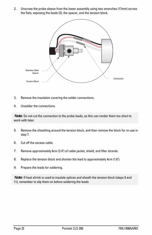
2. Unscrew the probe sleeve from the lower assembly using two wrenches (17mm) across the flats, exposing the leads (3), the spacer, and the tension block.
3. Remove the insulation covering the solder connections. 4. Unsolder the connections.
Note: Do not cut the connection to the probe leads, as this can render them too short to work with later.
5. Remove the sheathing around the tension block, and then remove the block for re-use in step 7.
6. Cut off the excess cable. 7. Remove approximately 6cm (2.4") of cable jacket, shield, and filler strands. 8. Replace the tension block and shorten the lead to approximately 4cm (1.6"). 9. Prepare the leads for soldering.
Note: If heat shrink is used to insulate splices and sheath the tension block (steps 9 and 11), remember to slip them on before soldering the leads.
Tension Block
Stainless SteelSpacer
Connection

7ML19985AR01 Pointek CLS 200 Page 23
10. Make the solder connections and insulate.
11. Remove the excess core. 12. Sheath the tension block. 13. Re-dress the probe sleeve thread with Teflon tape or sealant. 14. Reassemble the sleeve and cable gland. Insure that the cable is not turned excessively,
as this could break the leads. 15. Check unit for proper operation.
5cm(2")
CoreTensionBlock
Stainless SteelSpacer

Page 24 Pointek CLS 200 7ML19985AR01
Appendix 2: Approvals
WRITTEN DECLARATION OF CONFORMITY
We, Siemens Milltronics Process Instruments B.V. Nikkelstraat 10 - 4823 AB BREDA - The Netherlands
Declare, solely under own responsibility, that the product Point Level Switch, Pointek CLS 200
Mentioned in this declaration, complies with the following standards and/or normative documents: Requirements Remarks Certificate No Environment Commercial, light Industrial and industrial 2008949-KRQ/EMC 01-4229 EN 61326: 1998 Product group standard for Electrical equipment
for measurement, control and laboratory use, from which:
EN 55011: 1998 Emission Class B EN 61000-4-2: 1995 Electrostatic Discharge (ESD) Immunity EN 61000-4-3: 1996 Radiated Electro-Magnetic Field Immunity EN 61000-4-4: 1995 Electrostatic Fast Transient (EFT) Immunity EN 61000-4-5: 1995 Surge Transient Immunity EN 61000-4-6: 1996 Conducted Radio-Frequency Disturbances Immunity ATEX Directive 94/9/EC Audit Report No 2003068 KEMA 00ATEXQ3047 I 1/ 2 GD EEx d [ia] IIC T6T4 0344 KEMA 00ATEX2039X T 100 °C IP 66
EN 50014: 1992 General Requirements EN 50018: 1994 Flameproof Enclosures d EN 50020: 1994 Intrinsic Safety i EN 50284: 1999 Special Requirements for Category 1G Equipment EN 50281-1-1: 1998 Dust Ignition Proof
Notified body: N.V. KEMA Utrechtseweg 310 6812 AR Arnhem The Netherlands 97/23/EC Pressure Equipment Directive Lloyds Register, DAD No.: 8033472, 8033473, 8033628 Notified body: Stoomwezen B.V. Weena Zuid 168 3012 NC Rotterdam The Netherlands
Location: Breda Representative Name: C.S. van Gils Date: August 31, 2001 Function: Managing Director Remark: For specific safety specifications, please consult the instrument label.
7ML19985AR01 Pointek CLS 200 Page 25
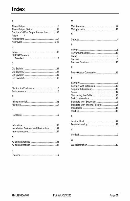
Index
A
Alarm Output ............................................................5 Alarm Output Status .............................................19 Ancillary 2-Wire Output Connection.................16 Angle 7 Applications ..............................................................4 Approvals ............................................................6, 26
C
Cable.........................................................................10 CLS 200 Versions
Standard...............................................................8
D
Dip Switch 1 ............................................................17 Dip Switch 2 ............................................................17 Dip Switch 4 ............................................................17 Dip Switch 5 ............................................................18
E
Electronics/Enclosure ............................................5 Environmental ..........................................................5
F
falling material........................................................13 Features .....................................................................4
H
Horizontal ..................................................................7
I
Indicators.................................................................18 Installation Features and Restrictions .............11 Interconnection......................................................14
K
K2 contact ratings .................................................15 K3 contact ratings .................................................15
L
Location .....................................................................7
M
Maintenance ..........................................................22 Multiple units..........................................................11
O
Outputs....................................................................... 4
P
Power ......................................................................... 5 Power Connection ................................................16 Probe .......................................................................... 6 Process ...................................................................... 5 Process Cautions ..................................................13
R
Relay Output Connection.....................................15
S
Sanitary...................................................................... 9 Sanitary with Extension.......................................10 Setpoint Adjustment .............................................19 Setup ........................................................................17 Shortening the Cable............................................23 Solid state switch..................................................15 Standard with Extension ....................................... 9 Standard with Thermal Isolator........................... 8 Standpipes ..............................................................11 Start Up....................................................................18
T
tension block ..........................................................24 Troubleshooting.....................................................22
V
Vertical ....................................................................... 7
W
Wall Restriction .....................................................12

IQ300IX.fm Page 5 Tuesday, October 2, 2001 1:43 PM

Notes
Notes.fm Page 1 Thursday, October 11, 2001 8:48 AM

Notes
Notes.fm Page 2 Thursday, October 11, 2001 8:48 AM

IQ300IX.fm Page 5 Tuesday, October 2, 2001 1:43 PM

©
Rev. 1.2