POINT Guard I/O Safety Modules, User Manual - Rockwell Automation
222
POINT Guard I/O Safety Modules Catalog Numbers 1734-IB8S, 1734-OB8S, 1734-IE4S User Manual
Transcript of POINT Guard I/O Safety Modules, User Manual - Rockwell Automation

POINT Guard I/O Safety ModulesCatalog Numbers 1734-IB8S, 1734-OB8S, 1734-IE4S
User Manual

Important User Information
Read this document and the documents listed in the additional resources section about installation, configuration, and operation of this equipment before you install, configure, operate, or maintain this product. Users are required to familiarize themselves with installation and wiring instructions in addition to requirements of all applicable codes, laws, and standards.
Activities including installation, adjustments, putting into service, use, assembly, disassembly, and maintenance are required to be carried out by suitably trained personnel in accordance with applicable code of practice.
If this equipment is used in a manner not specified by the manufacturer, the protection provided by the equipment may be impaired.
In no event will Rockwell Automation, Inc. be responsible or liable for indirect or consequential damages resulting from the use or application of this equipment.
The examples and diagrams in this manual are included solely for illustrative purposes. Because of the many variables and requirements associated with any particular installation, Rockwell Automation, Inc. cannot assume responsibility or liability for actual use based on the examples and diagrams.
No patent liability is assumed by Rockwell Automation, Inc. with respect to use of information, circuits, equipment, or software described in this manual.
Reproduction of the contents of this manual, in whole or in part, without written permission of Rockwell Automation, Inc., is prohibited.
Throughout this manual, when necessary, we use notes to make you aware of safety considerations.
Labels may also be on or inside the equipment to provide specific precautions.
Allen-Bradley, GuardLogix, Guardmaster, Logix5000, Logix Designer, POINT Guard I/O, Rockwell Automation, Rockwell Software, RSLinx, RSLogix 5000, RSNetWorx, SmartGuard, Studio 5000, and Studio 5000 Logix Designer are trademarks of Rockwell Automation, Inc.
Trademarks not belonging to Rockwell Automation are property of their respective companies.
WARNING: Identifies information about practices or circumstances that can cause an explosion in a hazardous environment,
which may lead to personal injury or death, property damage, or economic loss.
ATTENTION: Identifies information about practices or circumstances that can lead to personal injury or death, property
damage, or economic loss. Attentions help you identify a hazard, avoid a hazard, and recognize the consequence.
IMPORTANT Identifies information that is critical for successful application and understanding of the product.
SHOCK HAZARD: Labels may be on or inside the equipment, for example, a drive or motor, to alert people that dangerous
voltage may be present.
BURN HAZARD: Labels may be on or inside the equipment, for example, a drive or motor, to alert people that surfaces may
reach dangerous temperatures.
ARC FLASH HAZARD: Labels may be on or inside the equipment, for example, a motor control center, to alert people to
potential Arc Flash. Arc Flash will cause severe injury or death. Wear proper Personal Protective Equipment (PPE). Follow ALL
Regulatory requirements for safe work practices and for Personal Protective Equipment (PPE).

Summary of Changes
This manual contains new and updated information. Changes throughout this revision are marked by change bars, as shown to the right of this paragraph.
New and Updated Information
This table contains the changes made to this revision.
Topic Page
OB8S Safety Digital Output Module Features 19
Safety Inputs - Single Channel Mode 26
Appendix C Specifications 187
Series A Safety Data 190
Series B Safety Data 193
Product Failure Rates 196
Input Assemblies Table 201
Rockwell Automation Publication 1734-UM013K-EN-P - October 2015 3

Summary of Changes
Notes:
4 Rockwell Automation Publication 1734-UM013K-EN-P - October 2015

Table of Contents
Summary of Changes New and Updated Information . . . . . . . . . . . . . . . . . . . . . . . . . . . . . . . . . . . . . 3Preface Terminology. . . . . . . . . . . . . . . . . . . . . . . . . . . . . . . . . . . . . . . . . . . . . . . . . . . . . 11
Access Product Release Notes . . . . . . . . . . . . . . . . . . . . . . . . . . . . . . . . . . . . . 12Additional Resources . . . . . . . . . . . . . . . . . . . . . . . . . . . . . . . . . . . . . . . . . . . . . 13
Chapter 1POINT Guard I/O Overview Understand Suitability for Use . . . . . . . . . . . . . . . . . . . . . . . . . . . . . . . . . . . . 15
Safety Precautions . . . . . . . . . . . . . . . . . . . . . . . . . . . . . . . . . . . . . . . . . . . . . . . . 17Installing and Replacing Modules . . . . . . . . . . . . . . . . . . . . . . . . . . . . . . 17
POINT Guard I/O Modules in CIP Safety Systems. . . . . . . . . . . . . . . . . 181734-IB8S Digital Input Module Features . . . . . . . . . . . . . . . . . . . . . . 181734-OB8S Safety Digital Output Module Features. . . . . . . . . . . . . 191734-IE4S Safety Analog Input Module Features . . . . . . . . . . . . . . . 19Programming Requirements. . . . . . . . . . . . . . . . . . . . . . . . . . . . . . . . . . . 20CIP Safety Architectures . . . . . . . . . . . . . . . . . . . . . . . . . . . . . . . . . . . . . . 20
Safety Application Requirements . . . . . . . . . . . . . . . . . . . . . . . . . . . . . . . . . . 21
Chapter 2Safety Inputs, Safety Outputs, and Safety Data
Safe States . . . . . . . . . . . . . . . . . . . . . . . . . . . . . . . . . . . . . . . . . . . . . . . . . . . . . . . 23POINT Guard Digital I/O Modules . . . . . . . . . . . . . . . . . . . . . . . . . . . 23POINT Guard I/O Analog Input Module. . . . . . . . . . . . . . . . . . . . . . 24
Safety Inputs (1734-IB8S) . . . . . . . . . . . . . . . . . . . . . . . . . . . . . . . . . . . . . . . . 24Using a Test Output with a Safety Input . . . . . . . . . . . . . . . . . . . . . . . 24Single-channel Mode . . . . . . . . . . . . . . . . . . . . . . . . . . . . . . . . . . . . . . . . . 26Dual-channel Mode and Discrepancy Time. . . . . . . . . . . . . . . . . . . . . 27Dual-channel, Equivalent . . . . . . . . . . . . . . . . . . . . . . . . . . . . . . . . . . . . . 28Dual-channels, Complementary . . . . . . . . . . . . . . . . . . . . . . . . . . . . . . . 29Safety Input Fault Recovery . . . . . . . . . . . . . . . . . . . . . . . . . . . . . . . . . . . 30Input Delays . . . . . . . . . . . . . . . . . . . . . . . . . . . . . . . . . . . . . . . . . . . . . . . . . 30
Safety Analog Inputs (1734-IE4S) . . . . . . . . . . . . . . . . . . . . . . . . . . . . . . . . . 31Input Range. . . . . . . . . . . . . . . . . . . . . . . . . . . . . . . . . . . . . . . . . . . . . . . . . . 31Scaling. . . . . . . . . . . . . . . . . . . . . . . . . . . . . . . . . . . . . . . . . . . . . . . . . . . . . . . 31Digital Input Filter . . . . . . . . . . . . . . . . . . . . . . . . . . . . . . . . . . . . . . . . . . . 32Sensor Power Supply. . . . . . . . . . . . . . . . . . . . . . . . . . . . . . . . . . . . . . . . . . 32Channel Offset. . . . . . . . . . . . . . . . . . . . . . . . . . . . . . . . . . . . . . . . . . . . . . . 33Process Alarms . . . . . . . . . . . . . . . . . . . . . . . . . . . . . . . . . . . . . . . . . . . . . . . 33Using a Single-channel Sensor . . . . . . . . . . . . . . . . . . . . . . . . . . . . . . . . . 34Dual-channel Equivalent Mode. . . . . . . . . . . . . . . . . . . . . . . . . . . . . . . . 35Tachometer Mode. . . . . . . . . . . . . . . . . . . . . . . . . . . . . . . . . . . . . . . . . . . . 36
Safety Outputs (1734-OB8S) . . . . . . . . . . . . . . . . . . . . . . . . . . . . . . . . . . . . . 39Safety Output with Test Pulse . . . . . . . . . . . . . . . . . . . . . . . . . . . . . . . . . 39Dual-channel Mode . . . . . . . . . . . . . . . . . . . . . . . . . . . . . . . . . . . . . . . . . . 40Single-channel Mode . . . . . . . . . . . . . . . . . . . . . . . . . . . . . . . . . . . . . . . . . 41Safety Output Fault Recovery . . . . . . . . . . . . . . . . . . . . . . . . . . . . . . . . . 41
Muting Lamp Operation (1734-IB8S) . . . . . . . . . . . . . . . . . . . . . . . . . . . . . 42I/O Status Data . . . . . . . . . . . . . . . . . . . . . . . . . . . . . . . . . . . . . . . . . . . . . . . . . . 43
Rockwell Automation Publication 1734-UM013K-EN-P - October 2015 5

Table of Contents
Digital I/O Status Data . . . . . . . . . . . . . . . . . . . . . . . . . . . . . . . . . . . . . . . 44Analog I/O Status Data . . . . . . . . . . . . . . . . . . . . . . . . . . . . . . . . . . . . . . . 44
Chapter 3Guidelines for Placing Power Supplies and Modules in a System
Choosing a Power Supply . . . . . . . . . . . . . . . . . . . . . . . . . . . . . . . . . . . . . . . . . 45Power Supply Examples . . . . . . . . . . . . . . . . . . . . . . . . . . . . . . . . . . . . . . . . . . . 47
Example 1: Isolating Field Power Segments . . . . . . . . . . . . . . . . . . . . . 47Example 2: POINT Guard I/O Used with AC I/O Modules . . . . . 48
Placing Series A Digital and Analog Modules . . . . . . . . . . . . . . . . . . . . . . . 49Placing Series B Digital Modules . . . . . . . . . . . . . . . . . . . . . . . . . . . . . . . . . . . 50
Chapter 4Install the Module Precautions . . . . . . . . . . . . . . . . . . . . . . . . . . . . . . . . . . . . . . . . . . . . . . . . . . . . . . 52
European Hazardous Location Approval . . . . . . . . . . . . . . . . . . . . . . . 52North American Hazardous Location Approval . . . . . . . . . . . . . . . . . 53Environment and Enclosure . . . . . . . . . . . . . . . . . . . . . . . . . . . . . . . . . . . 53Preventing Electrostatic Discharge . . . . . . . . . . . . . . . . . . . . . . . . . . . . . 54
Mount the Module . . . . . . . . . . . . . . . . . . . . . . . . . . . . . . . . . . . . . . . . . . . . . . . 54Install the Mounting Base . . . . . . . . . . . . . . . . . . . . . . . . . . . . . . . . . . . . . 54Connect the Module to the Mounting Base . . . . . . . . . . . . . . . . . . . . . 56Connect the Removable Terminal Block. . . . . . . . . . . . . . . . . . . . . . . . 57Remove a Mounting Base. . . . . . . . . . . . . . . . . . . . . . . . . . . . . . . . . . . . . . 58
Wire Modules. . . . . . . . . . . . . . . . . . . . . . . . . . . . . . . . . . . . . . . . . . . . . . . . . . . . 58Terminal Layout. . . . . . . . . . . . . . . . . . . . . . . . . . . . . . . . . . . . . . . . . . . . . . 60
Connection Details . . . . . . . . . . . . . . . . . . . . . . . . . . . . . . . . . . . . . . . . . . . . . . . 61Wiring Examples . . . . . . . . . . . . . . . . . . . . . . . . . . . . . . . . . . . . . . . . . . . . . . . . . 63
Emergency Stop Dual-channel Devices . . . . . . . . . . . . . . . . . . . . . . . . . 63Single-channel Safety Contactor . . . . . . . . . . . . . . . . . . . . . . . . . . . . . . . 64Dual-channel Safety Contactors . . . . . . . . . . . . . . . . . . . . . . . . . . . . . . . 65Safety Analog Input Wiring . . . . . . . . . . . . . . . . . . . . . . . . . . . . . . . . . . . 66
6 Rockwell Automation Publication 1734-UM013K-EN-P - October 2015

Table of Contents
Chapter 5Configure the Module in a GuardLogix Controller System
Setting Up the Module . . . . . . . . . . . . . . . . . . . . . . . . . . . . . . . . . . . . . . . . . . . 75Add and Configure the Ethernet Bridge Module. . . . . . . . . . . . . . . . . . . . 76Add and Configure the 1734 Ethernet Adapter . . . . . . . . . . . . . . . . . . . . . 77Add and Configure Safety Digital Input Modules . . . . . . . . . . . . . . . . . . . 79
Add the Safety Digital Input Module. . . . . . . . . . . . . . . . . . . . . . . . . . . 79Configure the Safety Digital Inputs . . . . . . . . . . . . . . . . . . . . . . . . . . . . 84Configure the Test Outputs . . . . . . . . . . . . . . . . . . . . . . . . . . . . . . . . . . . 87
Add and Configure Safety Digital Output Modules . . . . . . . . . . . . . . . . . 88Add the Safety Digital Output Module . . . . . . . . . . . . . . . . . . . . . . . . . 88Configure the Safety Digital Outputs . . . . . . . . . . . . . . . . . . . . . . . . . . 92
Add and Configure Safety Analog Input Modules. . . . . . . . . . . . . . . . . . . 93Add the Safety Analog Input Module . . . . . . . . . . . . . . . . . . . . . . . . . . 93Configure the Safety Analog Input Channel Operation. . . . . . . . . . 96Configure the Safety Analog Inputs . . . . . . . . . . . . . . . . . . . . . . . . . . . . 97Configure Safety Analog Input Alarms (optional) . . . . . . . . . . . . . . . 98Configure Tachometer Operation . . . . . . . . . . . . . . . . . . . . . . . . . . . . 100
Values and States of Tags . . . . . . . . . . . . . . . . . . . . . . . . . . . . . . . . . . . . . . . . 102Configure Safety Connections . . . . . . . . . . . . . . . . . . . . . . . . . . . . . . . . . . . 104Configuration Ownership . . . . . . . . . . . . . . . . . . . . . . . . . . . . . . . . . . . . . . . 105Saving and Downloading the Module Configuration . . . . . . . . . . . . . . . 106Using ControlFLASH Software to Update POINT Guard I/O Modules 106
Chapter 6Configure the Module for a SmartGuard Controller
Before You Begin . . . . . . . . . . . . . . . . . . . . . . . . . . . . . . . . . . . . . . . . . . . . . . . 108Set the Node Address. . . . . . . . . . . . . . . . . . . . . . . . . . . . . . . . . . . . . . . . . . . . 108Auto-addressing with a 1734-PDN Adapter . . . . . . . . . . . . . . . . . . . . . . . 110Set Up Your DeviceNet Network . . . . . . . . . . . . . . . . . . . . . . . . . . . . . . . . 112Configure the POINT Guard I/O Modules . . . . . . . . . . . . . . . . . . . . . . . 113
Configure Digital Safety Inputs and Test Outputs . . . . . . . . . . . . . 113Configure Digital Safety Outputs . . . . . . . . . . . . . . . . . . . . . . . . . . . . . 116Configure Safety Analog Inputs . . . . . . . . . . . . . . . . . . . . . . . . . . . . . . 117
Configure the SmartGuard Controller . . . . . . . . . . . . . . . . . . . . . . . . . . . . 122Set Up the Input and Output Connections . . . . . . . . . . . . . . . . . . . . 122Complete the Set Up of the SmartGuard Controller . . . . . . . . . . . 126
Save and Download Module Configuration . . . . . . . . . . . . . . . . . . . . . . . 127
Rockwell Automation Publication 1734-UM013K-EN-P - October 2015 7

Table of Contents
Chapter 7Configuring Safety Connections between a GuardLogix Controller and POINT Guard I/O Modules on a DeviceNet Network
Configure the Module in RSNetWorx for DeviceNet Software. . . . . . 129Add the POINT Guard I/O Module to the Controller Project . . . . . . 130Complete the Safety Configuration . . . . . . . . . . . . . . . . . . . . . . . . . . . . . . . 134Download the DeviceNet Network Configuration . . . . . . . . . . . . . . . . . 136Verify Your DeviceNet Safety Configuration . . . . . . . . . . . . . . . . . . . . . . 137
Determine If Devices Can Be Verified . . . . . . . . . . . . . . . . . . . . . . . . . 138Select Devices to Verify. . . . . . . . . . . . . . . . . . . . . . . . . . . . . . . . . . . . . . . 139Review the Safety Device Verification Reports . . . . . . . . . . . . . . . . . 141Lock Safety Devices . . . . . . . . . . . . . . . . . . . . . . . . . . . . . . . . . . . . . . . . . . 141
Chapter 8Replacing POINT Guard I/O Modules The Safety Network Number. . . . . . . . . . . . . . . . . . . . . . . . . . . . . . . . . . . . . 143
Manually Setting the Safety Network Number . . . . . . . . . . . . . . . . . . . . . 144Resetting a Module to Out-of-box Condition. . . . . . . . . . . . . . . . . . . . . . 145
By Using the Logix Designer Application . . . . . . . . . . . . . . . . . . . . . . 146By Using RSNetWorx for DeviceNet Software . . . . . . . . . . . . . . . . . 147
Replacing a Module in a GuardLogix System on an EtherNet/IP Network 148
Replacement with ‘Configure Only When No Safety Signature Exists’ Enabled . . . . . . . . . . . . . . . . . . . . . . . . . . . . . . . . . . . . . . . . . . . . . . . . . . . . . 148Replacement with ‘Configure Always’ Enabled . . . . . . . . . . . . . . . . . 153
Replacing a Module When Using a SmartGuard or GuardLogix Controller on a DeviceNet Network . . . . . . . . . . . . . . . . . . . . . . . . . . . . . . 155
Appendix A Indicators Module . . . . . . . . . . . . . . . . . . . . . . . . . . . . . . . . . . . . . . . . . . . . . . . . . . . . . . . . 160
Network Status . . . . . . . . . . . . . . . . . . . . . . . . . . . . . . . . . . . . . . . . . . . . . . . . . 160Configuration Lock . . . . . . . . . . . . . . . . . . . . . . . . . . . . . . . . . . . . . . . . . . . . . 160Power . . . . . . . . . . . . . . . . . . . . . . . . . . . . . . . . . . . . . . . . . . . . . . . . . . . . . . . . . . 1611734-IE4S Sensor Power . . . . . . . . . . . . . . . . . . . . . . . . . . . . . . . . . . . . . . . . . 1611734-IE4S Safety Analog Input Status. . . . . . . . . . . . . . . . . . . . . . . . . . . . . 1611734-IB8S Safety Input Status . . . . . . . . . . . . . . . . . . . . . . . . . . . . . . . . . . . . 1611734-OB8S Safety Output Status . . . . . . . . . . . . . . . . . . . . . . . . . . . . . . . . . 162
Appendix BGet I/O Diagnostic Status from Modules in Logix Systems
Message Instructions. . . . . . . . . . . . . . . . . . . . . . . . . . . . . . . . . . . . . . . . . . . . . 163Configure the Message Instruction. . . . . . . . . . . . . . . . . . . . . . . . . . . . . . . . 164Class, Instance, and Attribute Data for I/O Modules . . . . . . . . . . . . . . . 165
8 Rockwell Automation Publication 1734-UM013K-EN-P - October 2015

Table of Contents
Appendix CSpecifications Technical Specifications for Series A Modules . . . . . . . . . . . . . . . . . . . . . 169
Safety Digital Input Module Specifications . . . . . . . . . . . . . . . . . . . . 169Safety Digital Output Module Specifications . . . . . . . . . . . . . . . . . . 171Safety Analog Input Module Specifications . . . . . . . . . . . . . . . . . . . . 172
Technical Specifications for Series B Modules . . . . . . . . . . . . . . . . . . . . . 181Safety Digital Input Module Specifications . . . . . . . . . . . . . . . . . . . . 181Safety Digital Output Module Specifications . . . . . . . . . . . . . . . . . . 184
Environmental Specifications . . . . . . . . . . . . . . . . . . . . . . . . . . . . . . . . . . . . 185Certifications . . . . . . . . . . . . . . . . . . . . . . . . . . . . . . . . . . . . . . . . . . . . . . . . . . . 187Legislations and Standards . . . . . . . . . . . . . . . . . . . . . . . . . . . . . . . . . . . . . . . 187
Appendix DSafety Data . . . . . . . . . . . . . . . . . . . . . . . . . . . . . . . . . . . . . . . . . . . . . . . . . . . . . . . . . . . . . . . . 189
Series A Safety Data . . . . . . . . . . . . . . . . . . . . . . . . . . . . . . . . . . . . . . . . . . . . . 190Series B Safety Data . . . . . . . . . . . . . . . . . . . . . . . . . . . . . . . . . . . . . . . . . . . . . 193Product Failure Rates (failures per hour) . . . . . . . . . . . . . . . . . . . . . . . . . . 196
Appendix EConfiguration Parameters . . . . . . . . . . . . . . . . . . . . . . . . . . . . . . . . . . . . . . . . . . . . . . . . . . . . . . . . . . . . . . . . 197
Appendix FI/O Assemblies Input Assemblies . . . . . . . . . . . . . . . . . . . . . . . . . . . . . . . . . . . . . . . . . . . . . . . . 201
Output Assemblies . . . . . . . . . . . . . . . . . . . . . . . . . . . . . . . . . . . . . . . . . . . . . . 202Analog Input Assemblies . . . . . . . . . . . . . . . . . . . . . . . . . . . . . . . . . . . . . . . . 202Configuration Assemblies. . . . . . . . . . . . . . . . . . . . . . . . . . . . . . . . . . . . . . . . 204Using Data from Modules Configured Via the Generic Profile . . . . . . 210
Appendix GHistory of Changes 1734-UM013I-EN-P,
May 2013 . . . . . . . . . . . . . . . . . . . . . . . . . . . . . . . . . . . . . . . . . . . . . . . . . . . . . . 2111734-UM013H-EN-P, August 2012. . . . . . . . . . . . . . . . . . . . . . . . . . . . . . 2111734-UM013G-EN-P, August 2012 . . . . . . . . . . . . . . . . . . . . . . . . . . . . . . 2111734-UM013F-EN-P, June 2012. . . . . . . . . . . . . . . . . . . . . . . . . . . . . . . . . 2111734-UM013E-EN-P, March 2012. . . . . . . . . . . . . . . . . . . . . . . . . . . . . . . 2121734-UM013D-EN-P, September 2011 . . . . . . . . . . . . . . . . . . . . . . . . . . 2121734-UM013C-EN-P, August 2010 . . . . . . . . . . . . . . . . . . . . . . . . . . . . . . 2121734-UM013B-EN-P, June 2009. . . . . . . . . . . . . . . . . . . . . . . . . . . . . . . . . 2131734-UM013A-EN-P, February 2009 . . . . . . . . . . . . . . . . . . . . . . . . . . . . 213
Index
Rockwell Automation Publication 1734-UM013K-EN-P - October 2015 9

Table of Contents
Notes:
10 Rockwell Automation Publication 1734-UM013K-EN-P - October 2015

Preface
Thoroughly read and understand this manual before installing and operating a system that uses POINT Guard I/O™ modules.
Always observe the following guidelines when using a module. In this manual, we use safety administrator to mean a person who is qualified, authorized, and responsible to secure safety in the design, installation, operation, maintenance, and disposal of the ‘machine’.
• Keep this manual in a safe place where personnel can refer to it when necessary.
• Use the module properly according to the installation environment, performance ratings, and functions of the machine.
See Understand Suitability for Use on page 15 and Safety Precautions on page 17.
Product specifications and accessories can change at any time. Consult with your Rockwell Automation representative to confirm specifications of purchased product. Dimensions and weights are nominal and are not for manufacturing purposes, even when tolerances are shown.
Consult your Rockwell Automation representative if you have any questions or comments. Also refer to the related documentation, which is listed on page 13, as necessary.
TerminologyTable 1 - Common Terms
Term Means
Connection Logical communication channel for communication between nodes. Connections are maintained and controlled between masters and slaves.
EDS Electronic data sheet, a template that is used in RSNetWorx™ software to display the configuration parameters, I/O data profile, and connection-type support for a given I/O module. RSNetWorx software uses these simple text files to identify products and commission them on a network.
ODVA Open DeviceNet Vendor Association, a nonprofit association of vendors that are established for the promotion of CIP networks.
PFD Probability of failure on demand, the average probability of a system to fail to perform its design function on demand.
PFH Probability of failure per hour, the probability of a system to have a dangerous failure occur per hour.
Proof test Periodic test performed to detect failures in a safety-related system so that, if necessary, the system can be restored to an as-new condition or as close as practical to this condition.
SNN Safety network number, which uniquely identifies a network across all networks in the safety system. You are responsible for assigning a unique number for each safety network or safety subnet within a system.
Standard Devices or portions of devices that do not participate in the safety function.
Rockwell Automation Publication 1734-UM013K-EN-P - October 2015 11

Preface
Access Product Release Notes Product release notes are available online within the Product Compatibility and Download Center.
1. From the Quick Links list on http://www.ab.com, choose Product Compatibility and Download Center.
2. From the Compatibility Scenarios tab or the Get Downloads tab, search for and choose your product.
3. Click the download icon to access product release notes.
12 Rockwell Automation Publication 1734-UM013K-EN-P - October 2015

Preface
Additional Resources These documents contain additional information concerning related products from Rockwell Automation.
You can view or download publications athttp://www.rockwellautomation.com/literature/. To order paper copies of technical documentation, contact your local Allen-Bradley distributor or Rockwell Automation sales representative.
Resource Description
POINT I/O™ Selection Guide, publication 1734-SG001 Provides selection information for POINT I/O™ modules. Additional publication references are listed as well.
GuardLogix® 5570 Controllers User Manual, publication 1756-UM022 Provides information on how to install, configure, program, and use GuardLogix 5570 controllers in Studio 5000 Logix Designer® projects.
GuardLogix 5570 Controller Systems Safety Reference Manual, publication 1756-RM099 Provides information on safety application requirements for GuardLogix 5570 controllers in Studio 5000 Logix Designer projects.
GuardLogix Controller Systems Safety Reference Manual, publication 1756-RM093 Provides information on safety system requirements and describes the GuardLogix® controller system.
GuardLogix Controllers User Manual, publication 1756-UM020 Provides information on how to install, configure, program, and use GuardLogix controllers in RSLogix 5000® projects.
GuardLogix Safety Application Instructions Safety Reference Manual, publication 1756-RM095
Provides reference information that describes the GuardLogix Safety Application Instruction Set.
SmartGuard 600 Controllers Safety Reference Manual, publication 1752-RM001 Describes SmartGuard™ 600-specific safety requirements and controller features.
Field Potential Distributor Installation Instructions, publication 1734-IN059 Provides installation information on 1734-FPD distributors.
POINT I/O 24V DC Expansion Power Supply Installation Instructions, publication 1734-IN058
Provides installation information on 1734-EP24DC power supplies.
POINT I/O 120/240V AC Expansion Power Supply Installation Instructions, publication 1734-IN017
Provides installation information on 1734-EPAC power supplies.
POINT I/O Wiring Base Assembly Installation Instructions, publication 1734-IN511 Provides installation information on 1734-TB and 1734-TBS assemblies.
POINT I/O One-piece Wiring Base Assembly Installation Instructions, publication 1734-IN028
Provides installation information on 1734-TOP, 1734-TOPS, 1734-TOP3, and 1734-TOP3S assemblies.
ODVA Media Planning and Installation Guide, http://www.odva.org Describes the required media components and how to plan for and install these required components.
Industrial Automation Wiring and Grounding Guidelines, publication 1770-4.1 Provides general guidelines for installing a Rockwell Automation industrial system.
Product Certifications website, http://www.ab.com Provides declarations of conformity, certificates, and other certification details.
Rockwell Automation Publication 1734-UM013K-EN-P - October 2015 13
http://www.literature.rockwellautomation.com/idc/groups/literature/documents/sg/1734-sg001_-en-p.pdf
http://www.literature.rockwellautomation.com/idc/groups/literature/documents/sg/1734-sg001_-en-p.pdf
http://www.literature.rockwellautomation.com/idc/groups/literature/documents/rm/1756-rm093_-en-p.pdf
http://www.literature.rockwellautomation.com/idc/groups/literature/documents/rm/1756-rm093_-en-p.pdf
http://www.literature.rockwellautomation.com/idc/groups/literature/documents/um/1756-um020_-en-p.pdf
http://www.literature.rockwellautomation.com/idc/groups/literature/documents/um/1756-um020_-en-p.pdf
http://www.literature.rockwellautomation.com/idc/groups/literature/documents/rm/1752-rm001_-en-p.pdf

Preface
Notes:
14 Rockwell Automation Publication 1734-UM013K-EN-P - October 2015

Chapter 1
POINT Guard I/O Overview
Use the POINT Guard I/O™ safety modules in the POINT I/O platform to distribute safety I/O on a safety-control network that meets the requirements up to and including SIL CL3, and PLe, Cat. 4 as defined in IEC 61508, IEC 61511, IEC 62061, and ISO 13849-1. POINT Guard I/O modules can be used with 1756 GuardLogix®, 1768 Compact GuardLogix, or SmartGuard™ 600 controllers.
You can configure the modules for use on DeviceNet networks by using the network configuration tool, RSNetWorx™ for DeviceNet software. For Ethernet networks, use the GuardLogix programming tool, the Logix Designer application.
Understand Suitability for Use
Rockwell Automation® is not responsible for conformity with any standards, codes, or regulations that apply to the combination of the products in your application or use of the product. See Legislations and Standards on page 187 for more information.
Take all necessary steps to determine the suitability of the products for the systems, machine, and equipment with which it is used.
Know and observe all prohibitions of use applicable to these products.
Use this equipment within its specified ratings.
Never use these products for an application that involves serious risk to life or property without making sure that the system as a whole was designed to address the risks. Be sure that Rockwell Automation products are properly rated and installed for the intended use within the overall equipment or system.
Topic Page
Understand Suitability for Use 15
Safety Precautions 17
POINT Guard I/O Modules in CIP Safety Systems 18
Safety Application Requirements 21
Rockwell Automation Publication 1734-UM013K-EN-P - October 2015 15

Chapter 1 POINT Guard I/O Overview
Verify that the POINT Guard I/O firmware revision is correct before you commission the safety system. Firmware information for safety I/O modules is available at http://www.rockwellautomation.com/products/certification/safety.
Verify that a safety administrator conducts a risk assessment on the machine and determines module suitability before installation.
TIP Field power must be applied to the 1734-IE4S module when updating
firmware.
ATTENTION: Personnel responsible for the application of safety-related
programmable electronic systems (PES) shall be aware of the safety
requirements in the application of the system and shall be trained in the use of
the system.
ATTENTION: Use only appropriate components or devices that comply with
relevant safety standards that correspond to the required safety category and
safety integrity level.
• Conformity to requirements of the safety category and safety integrity level must be determined for the entire system.
• We recommend that you consult a certification body regarding assessment of conformity to the required safety integrity level or safety category.
You are responsible for confirming compliance with the applicable standards for
the entire system.
Table 1 - Requirements for Controlling Devices
Device Requirement Allen-Bradley Bulletin Safety ComponentsEmergency stop switches Use approved devices with direct opening mechanisms that comply with IEC/EN
60947-5-1.Bulletin 800F, 800T
Door interlocking switches,limit switches
Use approved devices with direct opening mechanisms that comply with IEC/EN 60947-5-1 and capable of switching microloads of24V DC, 3 mA.
Bulletin 440K, 440G, 440H for interlock switchBulletin 440P, 802T for limit switch
Safety sensors Use approved devices that comply with the relevant product standards, regulations, and rules in the country where used.
Any Guardmaster® product
Relays with forcibly- guided contacts, contactors
Use approved devices with forcibly guided contacts that comply with EN 50205. For feedback purposes, use devices with contacts capable of switching micro loads of 24V DC, 3 mA.
Bulletin 700S, 100S
Other devices Evaluate whether devices used are appropriate to satisfy the requirements of safety category levels.
-
16 Rockwell Automation Publication 1734-UM013K-EN-P - October 2015

POINT Guard I/O Overview Chapter 1
Safety Precautions Observe these precautions for proper use of POINT Guard I/O modules.
Installing and Replacing Modules
When you clean a module, do not use the following: • Thinner• Benzene• Acetone
ATTENTION: As serious injury can occur due to loss of required safety function,
follow these safety precautions.
• Never use test outputs as safety outputs. Test outputs are not safety outputs.
• Do not use Ethernet, DeviceNet, or ControlNet standard I/O data or explicit message data as safety data.
• Do not use light-emitting diode (LED) status indicators on the I/O modules for safety operations.
• Do not connect loads beyond the rated value to the safety outputs.
• Apply properly specified voltages to the module. Applying inappropriate voltages can cause the module to fail to perform it’s specified function, which could lead to loss of safety functions or damage to the module.
• Wire the POINT Guard I/O modules properly following the wiring requirements and guidelines in Wire Modules on page 58.
• Set unique network node addresses before connecting devices to the network.
• Perform testing to confirm that device wiring, configuration, and operation is correct before starting system operation.
• Do not disassemble, repair, or modify the module. This can result in loss of safety functions.
ATTENTION: • Clear previous configuration data before connecting devices to the network or
connecting input or output power to the device.
• Configure the replacement device properly and confirm that it operates correctly.
• After installation of the module, a safety administrator must confirm the installation and conduct trial operation and maintenance.
Rockwell Automation Publication 1734-UM013K-EN-P - October 2015 17
Chapter 1 POINT Guard I/O Overview
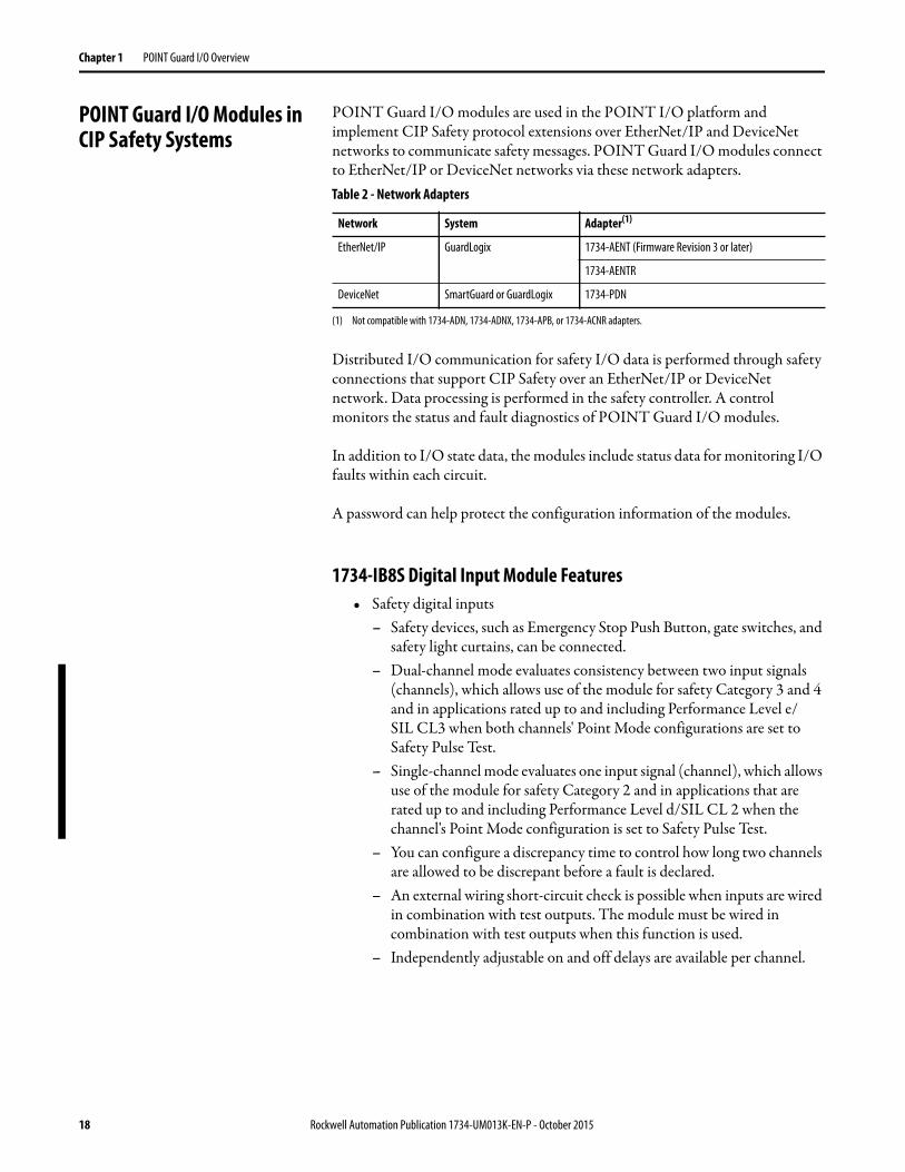
POINT Guard I/O Modules in CIP Safety Systems
POINT Guard I/O modules are used in the POINT I/O platform and implement CIP Safety protocol extensions over EtherNet/IP and DeviceNet networks to communicate safety messages. POINT Guard I/O modules connect to EtherNet/IP or DeviceNet networks via these network adapters.
Distributed I/O communication for safety I/O data is performed through safety connections that support CIP Safety over an EtherNet/IP or DeviceNet network. Data processing is performed in the safety controller. A control monitors the status and fault diagnostics of POINT Guard I/O modules.
In addition to I/O state data, the modules include status data for monitoring I/O faults within each circuit.
A password can help protect the configuration information of the modules.
1734-IB8S Digital Input Module Features• Safety digital inputs
– Safety devices, such as Emergency Stop Push Button, gate switches, and safety light curtains, can be connected.
– Dual-channel mode evaluates consistency between two input signals (channels), which allows use of the module for safety Category 3 and 4 and in applications rated up to and including Performance Level e/SIL CL3 when both channels' Point Mode configurations are set to Safety Pulse Test.
– Single-channel mode evaluates one input signal (channel), which allows use of the module for safety Category 2 and in applications that are rated up to and including Performance Level d/SIL CL 2 when the channel's Point Mode configuration is set to Safety Pulse Test.
– You can configure a discrepancy time to control how long two channels are allowed to be discrepant before a fault is declared.
– An external wiring short-circuit check is possible when inputs are wired in combination with test outputs. The module must be wired in combination with test outputs when this function is used.
– Independently adjustable on and off delays are available per channel.
Table 2 - Network Adapters
Network System Adapter(1)
(1) Not compatible with 1734-ADN, 1734-ADNX, 1734-APB, or 1734-ACNR adapters.
EtherNet/IP GuardLogix 1734-AENT (Firmware Revision 3 or later)
1734-AENTR
DeviceNet SmartGuard or GuardLogix 1734-PDN
18 Rockwell Automation Publication 1734-UM013K-EN-P - October 2015
POINT Guard I/O Overview Chapter 1
• Test outputs (digital input modules only)– Separate test outputs are provided for short-circuit detection of a safety
input (or inputs).– Power (24V) can be supplied to devices, such as safety sensors.– Test outputs can be configured as standard outputs.– Specific test outputs can be used for broken-wire detection of a muting
lamp.
1734-OB8S Safety Digital Output Module Features• Solid-state outputs• Dual-channel mode provides redundant control by using two output
signals (channels), which allows use of the module for safety Category 3 and 4, and applications that are rated up to and including Performance Level e/SIL CL3 when both channels' Point Mode configurations are set to Safety Pulse Test.
• Single-channel mode provides control by using one output signal (channel), which allows use of the module for safety Category 2, and applications that are rated up to and including Performance Level d/SIL CL2 when the channel's Point Mode configuration is set to Safety Pulse Test.
• Safety outputs can be pulse-tested to detect field wiring short circuits to 24V DC.
1734-IE4S Safety Analog Input Module Features• Connection of up to four voltage or current sensors.• Sensor power outputs are individually current-limited and monitored.• Measurement of process variables, such as temperature, pressure, or flow
rate.• Seven configurable input ranges
(±10V, ±5V, 0…5V, 0…10V, 4…20 mA, 0…20 mA, Tachometer).• Tachometer mode converts 24V DC switching signals into pulses per
second.• Single-channel or dual-channel for SIL 3-rated safety devices and
applications.• Dual-channel mode evaluates the consistency between two input signals
(channels), which allows use of the module in applications that are rated up to and including SIL CL3/PLe/Cat. 4.
• You can configure a discrepancy time to control how long two channels are allowed to be discrepant before a fault is declared.
IMPORTANT 1734-OB8S Single-channel mode is only certified for functional safety
applications with process safety times greater than or equal to 600 ms; or,
applications with demand rates less than or equal to 1 demand per minute.
Rockwell Automation Publication 1734-UM013K-EN-P - October 2015 19
Chapter 1 POINT Guard I/O Overview
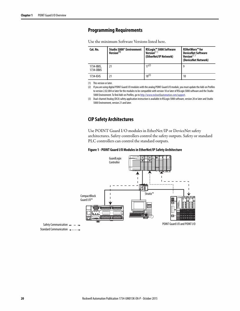
Programming Requirements
Use the minimum Software Versions listed here.
CIP Safety Architectures
Use POINT Guard I/O modules in EtherNet/IP or DeviceNet safety architectures. Safety controllers control the safety outputs. Safety or standard PLC controllers can control the standard outputs.
Figure 1 - POINT Guard I/O Modules in EtherNet/IP Safety Architecture
Cat. No. Studio 5000® Environment Version(1)
(1) This version or later.
RSLogix™ 5000 Software Version(EtherNet/IP Network)
RSNetWorx™ for DeviceNet Software Version(DeviceNet Network)
1734-IB8S, 1734-OB8S
21 17(2)
(2) If you are using digital POINT Guard I/O modules with the analog POINT Guard I/O module, you must update the Add-on Profiles
to version 2.02.004 or later for the modules to be compatible with version 18 or later of RSLogix 5000 software and the Studio
5000 Environment. To find Add-on Profiles, go to http://www.rockwellautomation.com/support.
9
1734-IE4S 21 18(3)
(3) Dual-channel Analog (DCA) safety application instruction is available in RSLogix 5000 software, version 20 or later and Studio
5000 Environment, version 21 and later.
10
Safety Communication
GuardLogix Controller
CompactBlock Guard I/O™
POINT Guard I/O and POINT I/O
Standard Communication
Stratix™
20 Rockwell Automation Publication 1734-UM013K-EN-P - October 2015

POINT Guard I/O Overview Chapter 1
Figure 2 - POINT Guard I/O Modules in DeviceNet Safety Architectures
Safety Application Requirements
POINT Guard I/O modules are certified for use in safety applications up to and including Performance Level e(PLe/Cat. 4) and Safety Integrity Level 3 (SIL CL3) in which the de-energized state is the safe state. Safety application requirements include evaluating probability of failure rates (PFD and PFH), system reaction time settings, and functional verification tests that fulfill SIL 3 criteria.
Creating, recording, and verifying the safety signature is also a required part of the safety application development process. The safety controller creates the safety signatures. The safety signature consists of an identification number, date, and time that uniquely identifies the safety portion of a project. This number includes all safety logic, data, and safety I/O configuration.
For safety system requirements, including information on the safety network number (SNN), verifying the safety signature, functional verification test intervals, system reaction time, and PFD/PFH calculations, refer to the following publications.
You must read, understand, and fulfill the requirements that are detailed in these publications before operating a safety system that uses POINT Guard I/O modules.
GuardLogix Controller
Guard I/O
POINT Guard I/O and POINT I/OSafety Communication
Standard Communication
SmartGuard Controller
For safety requirements in: See:
GuardLogix controller systems GuardLogix 5570 Controller Systems Safety Reference Manual, publication 1756-RM099
SmartGuard 600 controller systems SmartGuard 600 Controllers Safety Reference Manual, publication 1752-RM001
Rockwell Automation Publication 1734-UM013K-EN-P - October 2015 21

Chapter 1 POINT Guard I/O Overview
Notes:
22 Rockwell Automation Publication 1734-UM013K-EN-P - October 2015

Chapter 2
Safety Inputs, Safety Outputs, and Safety Data
Safe States POINT Guard Digital I/O Modules
The following are the safe states of the digital POINT Guard I/O modules: • Safety outputs: OFF • Safety input data to network: OFF (single channel and
dual-channel equivalent)• Safety input data to network: OFF/ON for input channels n/n+1
(dual-channel complimentary)
Figure 3 - Safety Status
The module is designed for use in applications where the safe state is the off state.
Topic Page
Safe States 23
Safety Inputs (1734-IB8S) 24
Safety Analog Inputs (1734-IE4S) 31
Safety Outputs (1734-OB8S) 39
I/O Status Data 43
ATTENTION: • The safe state of the outputs is defined as the off state.
• The safe state of the module and its data is defined as the off state.
• Use the POINT Guard I/O™ module only in applications where the off state is the safe state.
Output OFF Input
Inputs to Network OFFNetworks
Safety Status
44076
Rockwell Automation Publication 1734-UM013K-EN-P - October 2015 23

Chapter 2 Safety Inputs, Safety Outputs and Safety Data
POINT Guard I/O Analog Input Module
The following are the safe states of the POINT Guard I/O analog input module: • Safety input data to network in single-channel configuration: 0 (OFF)• Safety input data to network in dual-channel equivalent configuration:
– If a diagnostic fault occurs, the signal for the faulted channel is set to 0 (OFF).
– If a dual-channel discrepancy fault occurs, the dual-channel inputs continue to report actual input signals.
Safety Inputs (1734-IB8S) Safety inputs are used to monitor safety input devices.
Using a Test Output with a Safety Input
A test output can be used in combination with a safety input for short circuit, cross-channel, and open-circuit fault detection. Configure the test output as a pulse test source and associate it to a specific safety input.
Figure 4 - Example Use of a POINT Guard I/O Input Module
TIP The test output can also be configured as a power supply to source 24V DC
to an external device, for example, a light curtain.
I0 I1 I4 I5
I2 I3 I6 I7
COM COM COM COM
TO T1M T2 T3M
0
2
4
6
1
3
5
7
0
2
4
6
1
3
5
7
Where:T0 = Test Output 0 T1M = Test Output 1 with MutingT2 = Test Output 2 T3M = Test Output 3 with MutingI0…I7 = Safety Inputs
Safety Input Terminal
External Contact
24 Rockwell Automation Publication 1734-UM013K-EN-P - October 2015

Safety Inputs, Safety Outputs and Safety Data Chapter 2
Figure 5 - Test Pulse in a Cycle
For the 1734-IB8S module, the pulse width (X) is typically 525 μs; the pulse period (Y) is typically 144 ms.
When the external input contact is closed, a test pulse is output from the test output terminal to diagnose the field wiring and input circuitry. By using this function, short-circuits between inputs and 24V power, and between input signal lines and open circuits can be detected.
Figure 6 - Short-circuit between Input Signal Lines
X
OUT
Y
On
Off
��
��
�
IN+
24V
24V
0V
COM
T0
T1
IN0
IN1
External Contact
Short-circuit between Input Signal Lines and Power Supply (positive side)
External Contact
Short-circuit between Input Signal Lines44079
Rockwell Automation Publication 1734-UM013K-EN-P - October 2015 25
Chapter 2 Safety Inputs, Safety Outputs and Safety Data
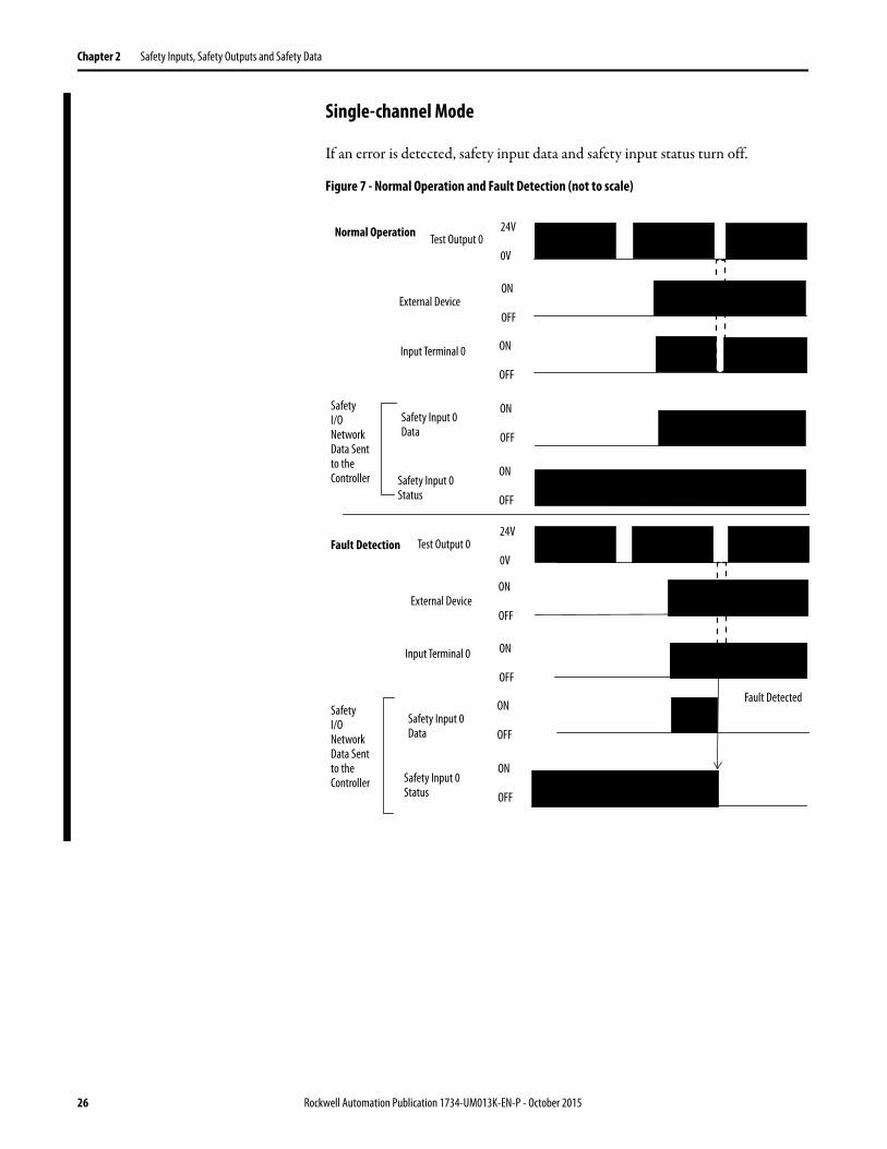
Single-channel Mode
If an error is detected, safety input data and safety input status turn off.
Figure 7 - Normal Operation and Fault Detection (not to scale)
24V
0V
Test Output 0
Input Terminal 0
External Device
Fault Detected
ON
OFF
ON
OFF
ON
OFF
ON
OFF
24V
0V
ON
OFF
Safety Input 0Status
Fault Detection
ON
OFF
ON
OFF
ON
OFF
Safety Input 0Status
Safety Input 0 Data
Safety Input 0 Data
Input Terminal 0
Normal Operation
External Device
Test Output 0
SafetyI/O NetworkData Sent to the Controller
SafetyI/O NetworkData Sent to the Controller
26 Rockwell Automation Publication 1734-UM013K-EN-P - October 2015
Safety Inputs, Safety Outputs and Safety Data Chapter 2
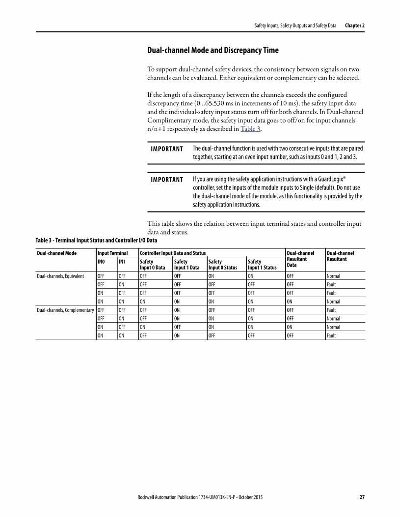
Dual-channel Mode and Discrepancy Time
To support dual-channel safety devices, the consistency between signals on two channels can be evaluated. Either equivalent or complementary can be selected.
If the length of a discrepancy between the channels exceeds the configured discrepancy time (0…65,530 ms in increments of 10 ms), the safety input data and the individual-safety input status turn off for both channels. In Dual-channel Complimentary mode, the safety input data goes to off/on for input channels n/n+1 respectively as described in Table 3.
This table shows the relation between input terminal states and controller input data and status.
IMPORTANT The dual-channel function is used with two consecutive inputs that are paired
together, starting at an even input number, such as inputs 0 and 1, 2 and 3.
IMPORTANT If you are using the safety application instructions with a GuardLogix®
controller, set the inputs of the module inputs to Single (default). Do not use
the dual-channel mode of the module, as this functionality is provided by the
safety application instructions.
Table 3 - Terminal Input Status and Controller I/O Data
Dual-channel Mode Input Terminal Controller Input Data and Status Dual-channelResultantData
Dual-channelResultantIN0 IN1 Safety
Input 0 DataSafety Input 1 Data
SafetyInput 0 Status
Safety Input 1 Status
Dual-channels, Equivalent OFF OFF OFF OFF ON ON OFF Normal
OFF ON OFF OFF OFF OFF OFF Fault
ON OFF OFF OFF OFF OFF OFF Fault
ON ON ON ON ON ON ON Normal
Dual-channels, Complementary OFF OFF OFF ON OFF OFF OFF Fault
OFF ON OFF ON ON ON OFF Normal
ON OFF ON OFF ON ON ON Normal
ON ON OFF ON OFF OFF OFF Fault
Rockwell Automation Publication 1734-UM013K-EN-P - October 2015 27

Chapter 2 Safety Inputs, Safety Outputs and Safety Data
Dual-channel, Equivalent
In Equivalent mode, both inputs of a pair must be in the same (equivalent) state. When a transition occurs in one channel of the pair before the transition of the second channel of the pair, a discrepancy occurs. If the second channel transitions to the appropriate state before the discrepancy time elapsing, the inputs are considered equivalent. If the second transition does not occur before the discrepancy time elapses, the channels will fault. In the fault state, the input and status for both channels are set low (OFF). When configured as an equivalent dual pair, the data bits for both channels are sent to the controller as equivalent, both high or both low.
Figure 8 - Equivalent, Normal Operation and Fault Detection (not to scale)ON
OFF
IN0
Safety Input 0Data
IN1
Fault Detected
Discrepancy Time
SafetyI/O NetworkData Sent to the Controller
ON
OFF
ON
OFF
ON
OFF
ON
OFF
ON
OFF
ON
OFF
IN0
Safety Input 0, 1Status
IN1
Fault Detection
ON
OFF
ON
OFF
ON
OFF
Discrepancy Time
Safety Input 0, 1Status
Safety Input 1 Data
Safety Input 1Data
Safety Input 0Data
Normal Operation
SafetyI/O NetworkData Sent to the Controller
28 Rockwell Automation Publication 1734-UM013K-EN-P - October 2015
Safety Inputs, Safety Outputs and Safety Data Chapter 2
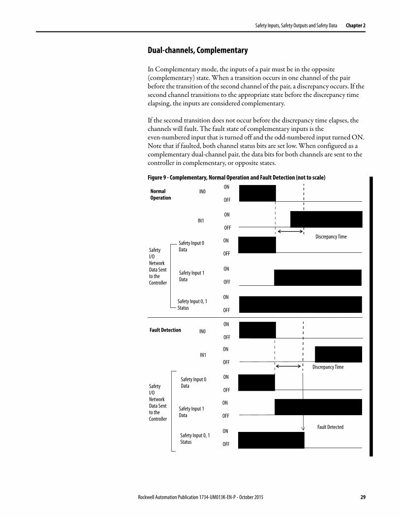
Dual-channels, Complementary
In Complementary mode, the inputs of a pair must be in the opposite (complementary) state. When a transition occurs in one channel of the pair before the transition of the second channel of the pair, a discrepancy occurs. If the second channel transitions to the appropriate state before the discrepancy time elapsing, the inputs are considered complementary.
If the second transition does not occur before the discrepancy time elapses, the channels will fault. The fault state of complementary inputs is the even-numbered input that is turned off and the odd-numbered input turned ON. Note that if faulted, both channel status bits are set low. When configured as a complementary dual-channel pair, the data bits for both channels are sent to the controller in complementary, or opposite states.
Figure 9 - Complementary, Normal Operation and Fault Detection (not to scale) ON
OFF
IN0
Safety Input 0 Data
IN1
Fault Detected
Discrepancy Time
ON
OFF
ON
OFF
ON
OFF
ON
OFF
ON
OFF
ON
OFF
IN0
Safety Input 0, 1Status
IN1
Fault Detection
ON
OFF
ON
OFF
ON
OFF
Discrepancy Time
Safety Input 0, 1Status
Safety Input 1 Data
Safety Input 1Data
Safety Input 0Data
Normal Operation
SafetyI/O NetworkData Sent to the Controller
SafetyI/O NetworkData Sent to the Controller
Rockwell Automation Publication 1734-UM013K-EN-P - October 2015 29

Chapter 2 Safety Inputs, Safety Outputs and Safety Data
Safety Input Fault Recovery
If an error is detected, the safety input data remains in the OFF state. Follow this procedure to activate the safety input data again.
1. Remove the cause of the error.
2. Place the safety input (or safety inputs) into the safe state.
3. Allow the input-error latch time to elapse.
After these steps are completed, the I/O indicator (red) turns off. The input data is now active.
Input Delays
On-delay—An input signal is treated as Logic 0 during the on-delay time (0…126 ms, in increments of 6 ms) after the rising edge of the input contact. The input turns on only if the input contact remains on after the on-delay time has elapsed. This setting helps prevent rapid changes of the input data due to contact bounce.
Figure 10 - On-delay
Off-delay—An input signal is treated as Logic 1 during the off-delay time (0…126 ms, in increments of 6 ms) after the falling edge of the input contact. The input turns off only if the input contact remains off after the off delay time has elapsed. This setting helps prevent rapid changes of the input data due to contact bounce.
Figure 11 - Off-delay
44094On-delay
ONOFF
ONOFF
Input Signal
Safety Input Network Data
44095
Safety Input Network Data
Off-delay
Input Signal ONOFF
ONOFF
30 Rockwell Automation Publication 1734-UM013K-EN-P - October 2015
Safety Inputs, Safety Outputs and Safety Data Chapter 2
Safety Analog Inputs (1734-IE4S)
Safety analog-input channels can be configured for current, voltage, or tachometer inputs, and for input type: single-channel or dual-channel equivalent.
Input Range
You configure the module for the following voltage or current input ranges, or for tachometer inputs.
• ±10V• ±5V• 0…5V• 0…10V• 4…20 mA• 0…20 mA• Tachometer (1…1000 Hz)
Scaling
The module converts input signals to the engineering units specified when you configure the module. You set the High Engineering value and the Low Engineering value to which the module scales the input signal before sending the data to the application program of the controller.
IMPORTANT If you are using the module with a GuardLogix® controller, set the inputs of the
module to Single (default). Do not use the dual-channel equivalent mode of
the modules with the GuardLogix dual channel safety application instructions,
as dual-channel functionality is provided by the GuardLogix instructions.
IMPORTANT When ±10V and ±5V ranges are selected, you must make sure that a
broken-wire condition is not a safety hazard. A broken wire causes the analog
value to transition to 0, which is within the valid input range. Therefore, status
bits do not indicate the broken-wire condition.
EXAMPLE The module is configured as follows:
• Input Range = 0…10V
• Low Engineering value = 0
• High Engineering value = 10,000
If the incoming signal is 1V, the data is 1000.
If the incoming signal is 5.5V, the data is 5500.
Rockwell Automation Publication 1734-UM013K-EN-P - October 2015 31

Chapter 2 Safety Inputs, Safety Outputs and Safety Data
Digital Input Filter
A single-pole, anti-aliasing filter of 10 Hz is followed by a four-pole digital filter. Choose from the following available corner frequencies.
• 1 Hz• 5 Hz• 10 Hz• 50 Hz
The default input filter setting is 1 Hz.
Figure 12 - Filter Operation
The filter setting affects the step response of the module. See the technical specifications for the 1734-IE4S module, beginning on page 166.
For the analog input modes, the input filter settings set the low-pass filter to filter out noise that can be present on the signal. In Tachometer mode, the input filter removes noise that can be present on the calculated frequency, effectively changing how rapidly the tachometer frequency changes to provide a value with less jitter.
Sensor Power Supply
You can configure the module to supply power to the connected sensors, or you can supply power to the sensors from an external power supply. To comply with UL restrictions, field power and connected devices must be powered by one, Class 2-complaint power supply.
We recommend that you configure the module to supply power to the sensors. This configuations lets the module detect if a sensor loses power, if the sensor is drawing too much power, or if there is a short in the power wiring to the sensor.
At powerup or after a reconfiguration, each sensor power supply is tested by being turned on for 500 ms.
Configurable Digital Filter SettingsN = 1 Hz, 5 Hz, 10 Hz, or 50 Hz
Anti-alias Filter10 Hz
1 pole 1 pole 1 pole 1 pole 1 pole
N N N N
32 Rockwell Automation Publication 1734-UM013K-EN-P - October 2015
Safety Inputs, Safety Outputs and Safety Data Chapter 2
When a channel is configured for module sensor power, a sensor power diagnostic is executed on that channel at powerup. The diagnostic is used to make sure that the sensors are not drawing over- or under-current and that channel-to-channel shorts are not present.
Channel Offset
You can configure an offset when differences in the sensors nominal input signals would otherwise exceed the desired discrepancy deadband. Use the Channel Offset if you are using two sensors of different types to measure the same variable. Sensors from two different vendors potentially give slightly differing data values for a given temperature or pressure. Use the Channel Offset to bring the data values back together. You can also use the Channel Offset with two identical sensors that are physically offset from each other.
The channel offset is applied before the channel discrepancy is evaluated.
Process Alarms
Process alarms alert you when an analog input value has exceeded the configured high or low limits for each channel. Process alarms are set at four configurable trigger points.
• High High alarm• High alarm• Low alarm• Low Low alarm
TIP When a sensor power over-current condition occurs, it can take as much as 15
seconds longer than the configured latch time for channel status to recover
after the over-current condition is cleared.
IMPORTANT If you use an external power supply, you must monitor the system for the
following:
• The supply voltage must be within the operating range of the sensor.
• The current draw of the sensors must not be over- or under-current, which could indicate a problem with the components of the sensor.
• Channel-to-channel shorts must be detected, if they occur.
TIP The Channel Offset is applied only during the evaluation of discrepancy between
two channels that are configured for Dual Channel and is not applied to any of the
Process Alarms. Therefore, if you are using two sensors to measure the same process
variable, and these sensors read different values, you potentially need to set the
Process Alarms to different values based on the sensor readings.
Rockwell Automation Publication 1734-UM013K-EN-P - October 2015 33

Chapter 2 Safety Inputs, Safety Outputs and Safety Data
You can configure a tolerance range, called a deadband, to work with process alarms. This deadband lets the process alarm status bit remain set, despite the alarm condition disappearing, as long as the data remains within the deadband of the process alarm.
Figure 13 - Alarms
Using a Single-channel Sensor
You must address the following requirements to meet SIL 3 with a single-channel sensor.
• The module’s ±10V and ±5V analog input modes must not be used for SIL 3 with a single-channel sensor because 0V falls within the valid input range. Therefore, a stuck at ground fault cannot be detected.
• In a single-channel sensor system, you must use other methods to make sure a channel-to-channel short cannot occur because these faults cannot be detected.
• If you are using a 3-wire sensor, you must verify its behavior to make sure that if it loses its ground connection, the signal is 0 (safe state) at the module input when the fault occurs.
IMPORTANT If you are using the safety application instructions with a GuardLogix controller,
do not use the process alarm of the module. Instead, perform analog range
checking in your application logic.
High High alarm turns OFF. High alarm remains ON.High High alarm turns ON. High alarm remains ON.
High alarm turns ON.
High alarm turns OFF.
Normal input rangeLow alarm turns
ON.Low alarm turns OFF.
Low Low alarm turns OFF. Low alarm remains ON.Low Low alarm turns ON. Low alarm remains ON.
Alarm deadbands
High High Alarm
High Alarm
Low Low Alarm
Low Alarm
34 Rockwell Automation Publication 1734-UM013K-EN-P - October 2015
Safety Inputs, Safety Outputs and Safety Data Chapter 2
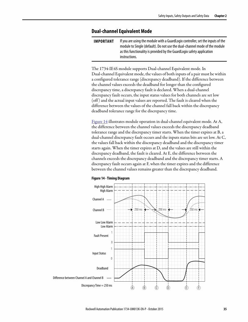
Dual-channel Equivalent Mode
The 1734-IE4S module supports Dual-channel Equivalent mode. In Dual-channel Equivalent mode, the values of both inputs of a pair must be within a configured tolerance range (discrepancy deadband). If the difference between the channel values exceeds the deadband for longer than the configured discrepancy time, a discrepancy fault is declared. When a dual-channel discrepancy fault occurs, the input status values for both channels are set low (off ) and the actual input values are reported. The fault is cleared when the difference between the values of the channel fall back within the discrepancy deadband tolerance range for the discrepancy time.
Figure 14 illustrates module operation in dual-channel equivalent mode. At A, the difference between the channel values exceeds the discrepancy deadband tolerance range and the discrepancy timer starts. When the timer expires at B, a dual-channel discrepancy fault occurs and the inputs status bits are set low. At C, the values fall back within the discrepancy deadband and the discrepancy timer starts again. When the timer expires at D, and the values are still within the discrepancy deadband, the fault is cleared. At E, the difference between the channels exceeds the discrepancy deadband and the discrepancy timer starts. A discrepancy fault occurs again at F, when the timer expires and the difference between the channel values remains greater than the discrepancy deadband.
Figure 14 - Timing Diagram
IMPORTANT If you are using the module with a GuardLogix controller, set the inputs of the
module to Single (default). Do not use the dual-channel mode of the module
as this functionality is provided by the GuardLogix safety application
instructions.
1
0
A B C
0
1
D
250 ms 250 ms
E F
250 ms
High High AlarmHigh Alarm
Low Low AlarmLow Alarm
Channel A
Channel B
Discrepancy Time = 250 ms
Fault Present
Input Status
Deadband
Difference between Channel A and Channel B
Rockwell Automation Publication 1734-UM013K-EN-P - October 2015 35
Chapter 2 Safety Inputs, Safety Outputs and Safety Data
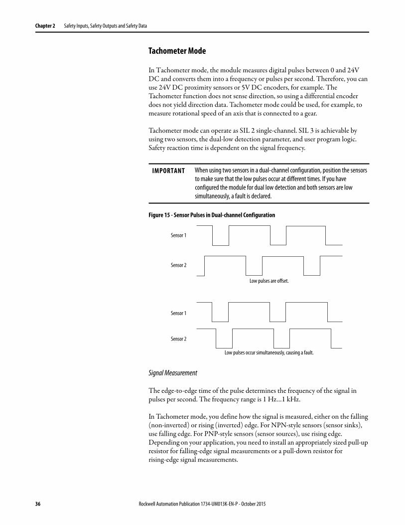
Tachometer Mode
In Tachometer mode, the module measures digital pulses between 0 and 24V DC and converts them into a frequency or pulses per second. Therefore, you can use 24V DC proximity sensors or 5V DC encoders, for example. The Tachometer function does not sense direction, so using a differential encoder does not yield direction data. Tachometer mode could be used, for example, to measure rotational speed of an axis that is connected to a gear.
Tachometer mode can operate as SIL 2 single-channel. SIL 3 is achievable by using two sensors, the dual-low detection parameter, and user program logic. Safety reaction time is dependent on the signal frequency.
Figure 15 - Sensor Pulses in Dual-channel Configuration
Signal Measurement
The edge-to-edge time of the pulse determines the frequency of the signal in pulses per second. The frequency range is 1 Hz…1 kHz.
In Tachometer mode, you define how the signal is measured, either on the falling (non-inverted) or rising (inverted) edge. For NPN-style sensors (sensor sinks), use falling edge. For PNP-style sensors (sensor sources), use rising edge. Depending on your application, you need to install an appropriately sized pull-up resistor for falling-edge signal measurements or a pull-down resistor for rising-edge signal measurements.
IMPORTANT When using two sensors in a dual-channel configuration, position the sensors
to make sure that the low pulses occur at different times. If you have
configured the module for dual low detection and both sensors are low
simultaneously, a fault is declared.
Low pulses are offset.
Sensor 1
Sensor 2
Low pulses occur simultaneously, causing a fault.
Sensor 1
Sensor 2
36 Rockwell Automation Publication 1734-UM013K-EN-P - October 2015

Safety Inputs, Safety Outputs and Safety Data Chapter 2
Figure 16 - Pulse Trains
Off and On Signal Levels
You configure the Off and On levels, in 1V increments, for the signal. When selecting these levels, assume a tolerance of at least ±0.5V. For example, if you set the On Level to 10V, you can expect the module to recognize a signal between 9.5 and 10.5V as On. While the accuracy of the module when measuring the analog signal is good, Tachometer mode emphasizes a wider voltage range and speed to be able to measure pulse widths accurately.
Also consider the variance of the voltage output from your sensor when making the On and Off Level settings. If possible, we recommend selecting On Levels that are 2V below and Off Levels that are 2V above the actual thresholds of the expected output voltage level of your device.
Determining Frequency in Pulses per Second
The edge-to-edge time of either the falling or rising edge of the pulse determines the frequency in pulses per second.
One pulse, by itself, does not generate a non-zero frequency. To report a frequency of 1 Hz, two falling or rising edge pulses must be detected within 1 second. The module reports 0 Hz until 1 Hz is detected. For example, if a falling or rising edge is not detected for 1.02 seconds after the previous edge, the module reports 0 Hz.
Ideal Pulse TrainFalling and rising edges are well-defined.
Rising edges are not well-defined.
Falling edges are not well-defined.
Falling Edge Rising Edge
Pull-down resistor helps define falling edges.
Pull-up resistor helps define rising edges.
Falling edge measurement
Rising edge measurement
Rockwell Automation Publication 1734-UM013K-EN-P - October 2015 37

Chapter 2 Safety Inputs, Safety Outputs and Safety Data
Overfrequency Bit Operation
When the frequency exceeds 1 kHz, the module reports a data value of 1 kHz, sets the Overfrequency status bit to 0, and latches it. While the Overfrequency bit is set to 0, you must use an alternate method to monitor the frequency of the system because the value reported by the module is latched at 1 kHz. Once you have verified that the frequency is lower than 1 kHz, you can reset the Overfrequency condition by setting the Reset Tach bit, which lets the module begin measuring the frequency of field pulses again.
If you set the Reset Tach bit while the frequency is still above 1 kHz, the Tachometer Overfrequency bit transitions to 1 (within range) momentarily. However, as soon as the module begins to measure pulses, it detects another overfrequency condition and immediately set the Tachometer Overfrequency bit to 0 again. The Reset Tach bit is edge-sensitive.
See Output Assemblies on page 202 for more information on resetting the Overfrequency bit.
Figure 17 - Overfrequency Operation
In Figure 17, the module reports a frequency of 0 Hz until the frequency of the system reaches 1 Hz at A, when the module begins reporting the actual value. At B, the frequency exceeds 1 kHz, the Overfrequency bit is set to 0, and the module continues to report a data value of 1 kHz. Between B and C, you must monitor the frequency by an alternate method because the value reported by the module is not always accurate. After C, the Overfrequency condition can be cleared, provided you have used an alternate method to verify that the actual frequency is below 1 kHz.
ATTENTION: Before resetting the Overfrequency condition, you must use
another method to verify that the actual frequency is lower than 1 kHz.
A B C
1 kHz
1 Hz
Frequency = 0Actual values are
reported.
Monitor frequency via an alternate method. Overfrequency
condition can be cleared.
Frequency = 1 Hz
Overfrequency bit is set to 0.Frequency = 1000 Hz
38 Rockwell Automation Publication 1734-UM013K-EN-P - October 2015

Safety Inputs, Safety Outputs and Safety Data Chapter 2
Safety Outputs (1734-OB8S) Read this section for information about safety outputs.
Safety Output with Test Pulse
When the safety output is on, the safety output can be configured to pulse test the safety output channel. By using this function, you can continuously test the ability of the safety output to remove power from the output terminals of the module. If an error is detected, the safety output data and individual safety output status turn off.
Figure 18 - Test Pulse in a Cycle
For the 1734-OB8S module, the pulse width (X) is typically 475 μs; the pulse period (Y) is typically 575 ms.
IMPORTANT To help prevent the test pulse from causing the connected device to
malfunction, pay careful attention to the input response time of the output
device.
44096
XY
OUT On
Off
Rockwell Automation Publication 1734-UM013K-EN-P - October 2015 39

Chapter 2 Safety Inputs, Safety Outputs and Safety Data
Dual-channel Mode
When the data of both channels is in the on state, and neither channel has a fault, the outputs are turned on. The status is normal. If a fault is detected on one channel, the safety output data and individual safety output status turn off for both channels.
Figure 19 - Dual-channel Setting (not to scale)
ON
OFF
OUT0
Safety Output 0, 1Status
OUT0
OUT1
OUT1
Safety Output 0, 1Status
Fault Detection
Error Detected
ON
OFF
ON
OFF
ON
OFF
ON
OFF
ON
OFF
Normal Operation
SafetyI/O NetworkData Sent to the Controller
SafetyI/O NetworkData Sent to the Controller
40 Rockwell Automation Publication 1734-UM013K-EN-P - October 2015
Safety Inputs, Safety Outputs and Safety Data Chapter 2
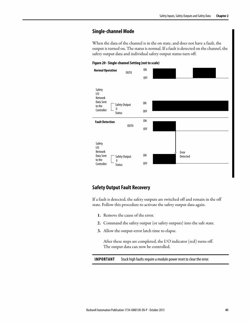
Single-channel Mode
When the data of the channel is in the on state, and does not have a fault, the output is turned on. The status is normal. If a fault is detected on the channel, the safety output data and individual safety output status turn off.
Figure 20 - Single-channel Setting (not to scale)
Safety Output Fault Recovery
If a fault is detected, the safety outputs are switched off and remain in the off state. Follow this procedure to activate the safety output data again.
1. Remove the cause of the error.
2. Command the safety output (or safety outputs) into the safe state.
3. Allow the output-error latch time to elapse.
After these steps are completed, the I/O indicator (red) turns off. The output data can now be controlled.
IMPORTANT Stuck high faults require a module power reset to clear the error.
ON
OFF
OUT0
Safety Output 0 Status
OUT0
Safety Output 0Status
Fault Detection
Error Detected
ON
OFF
ON
OFF
ON
OFF
Normal Operation
SafetyI/O NetworkData Sent to the Controller
SafetyI/O NetworkData Sent to the Controller
Rockwell Automation Publication 1734-UM013K-EN-P - October 2015 41
Chapter 2 Safety Inputs, Safety Outputs and Safety Data
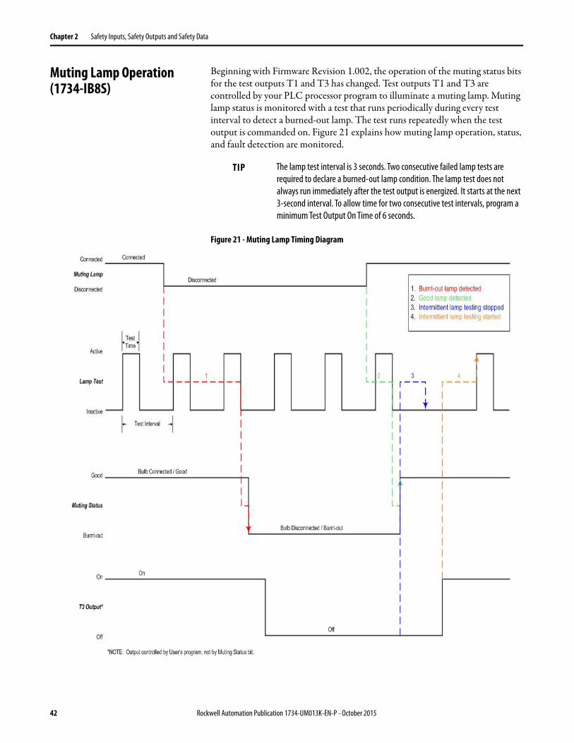
Muting Lamp Operation (1734-IB8S)
Beginning with Firmware Revision 1.002, the operation of the muting status bits for the test outputs T1 and T3 has changed. Test outputs T1 and T3 are controlled by your PLC processor program to illuminate a muting lamp. Muting lamp status is monitored with a test that runs periodically during every test interval to detect a burned-out lamp. The test runs repeatedly when the test output is commanded on. Figure 21 explains how muting lamp operation, status, and fault detection are monitored.
Figure 21 - Muting Lamp Timing Diagram
TIP The lamp test interval is 3 seconds. Two consecutive failed lamp tests are
required to declare a burned-out lamp condition. The lamp test does not
always run immediately after the test output is energized. It starts at the next
3-second interval. To allow time for two consecutive test intervals, program a
minimum Test Output On Time of 6 seconds.
42 Rockwell Automation Publication 1734-UM013K-EN-P - October 2015
Safety Inputs, Safety Outputs and Safety Data Chapter 2
Table 4 shows the expected behavior of the muting status for test outputs T1 and T3. Keep these points in mind as well:
• When power is applied to the 1734-IB8S module, and T1 or T3 remains commanded off, the muting status defaults to on.
This bit operation is designed to help prevent erroneous muting instruction faults from the GuardLogix controller. This bit status is not always the true indication of a burned-out lamp.
• If a muting lamp circuit is open when power is applied to the module, the condition is detected when the test output is commanded on.
• When a lamp burns out and is replaced, the fault (muting status bit) returns to the normal condition, independent of the state of the test output.
I/O Status Data In addition to I/O data, the module provides status data for monitoring the I/O circuits. The status includes diagnostic data that the controllers can read with 1 = ON/Normal and 0 = OFF/Fault/Alarm.
IMPORTANT Before checking the state of the corresponding muting status, be sure that the
test output is commanded on. Once the test output is commanded on, a
maximum time of 6 seconds is required for the module to detect a burned-out
lamp.
Table 4 - Muting Status Bit Operation
Test Output Commanded State
Lamp Condition Muting Status Bit
Description
ON Bad (open circuit) 0 Repair lamp.
ON Good 1 Normal condition. Lamp is operating properly.
OFF Bad (open circuit) 0 If lamp remains OFF after T1/T3 output cycled, repair lamp.
OFF Good 1 Normal condition.
Rockwell Automation Publication 1734-UM013K-EN-P - October 2015 43

Chapter 2 Safety Inputs, Safety Outputs and Safety Data
Digital I/O Status Data
The following data is monitored:• Individual Point Input Status• Combined Input Status• Individual Point Output Status • Combined Output Status• Individual Test Output Status• Individual Output Monitor (actual ON/OFF state of the outputs)
Individual Point status indicates whether each safety input, safety output, or test output is normal (normal: ON, faulted: OFF). For fatal errors, communication connections can be broken, so the status data cannot be read. Status bits are OFF in the controller data table when the connection is lost.
Combined status is provided by an AND of the status of all safety inputs or all safety outputs. When all inputs or outputs are normal, the respective combined status is ON. When one or more of them has an error, the respective combined status is OFF. This status is known as the combined safety input status or combined safety output status.
Analog I/O Status Data
Individual input status indicates whether each analog input point is normal (ON) or faulted (OFF). In addition, the following diagnostic data is monitored:
• User 24V Supply Overrange or Underrange• Sensor Power Overcurrent or Undercurrent• Channel Signal Overrange or Underrange• Broken Wire Detected (4…20 mA current mode)• Single-channel Discrepancy Error (channel fault)
In SIL 2 or SIL 3 operation, a single-channel discrepancy error occurs when both measurements (internal to the module) of the same input signal are not within tolerance. If a single-channel discrepancy occurs, indicating a problem with the module, input status is set to zero and a zero input value is reported for that channel.
• SIL 3 Dual-channel Discrepancy Error (channel fault)• Alarms
– High High and Low Low Alarm Overrange or Underrange– High and Low Alarms Overrange or Underrange– Dual-channel Tachometer Dual Low Inputs Detected– Tachometer Frequency Overrange or Underrange
The alarm status is reported in the Alarm Status attribute for each channel.
44 Rockwell Automation Publication 1734-UM013K-EN-P - October 2015
Chapter 3
Guidelines for Placing Power Supplies and Modules in a System
Choosing a Power Supply The POINTBus™ backplane includes a 5V communication bus and field power bus that get their power from a communication adapter or expansion power supplies. All POINT I/O™ modules are powered from the POINTBus backplane by either the adapter or expansion power supply. POINT I/O adapters have built-in power supplies. Use the information and examples in this chapter to determine if you need an expansion power supply in your system.
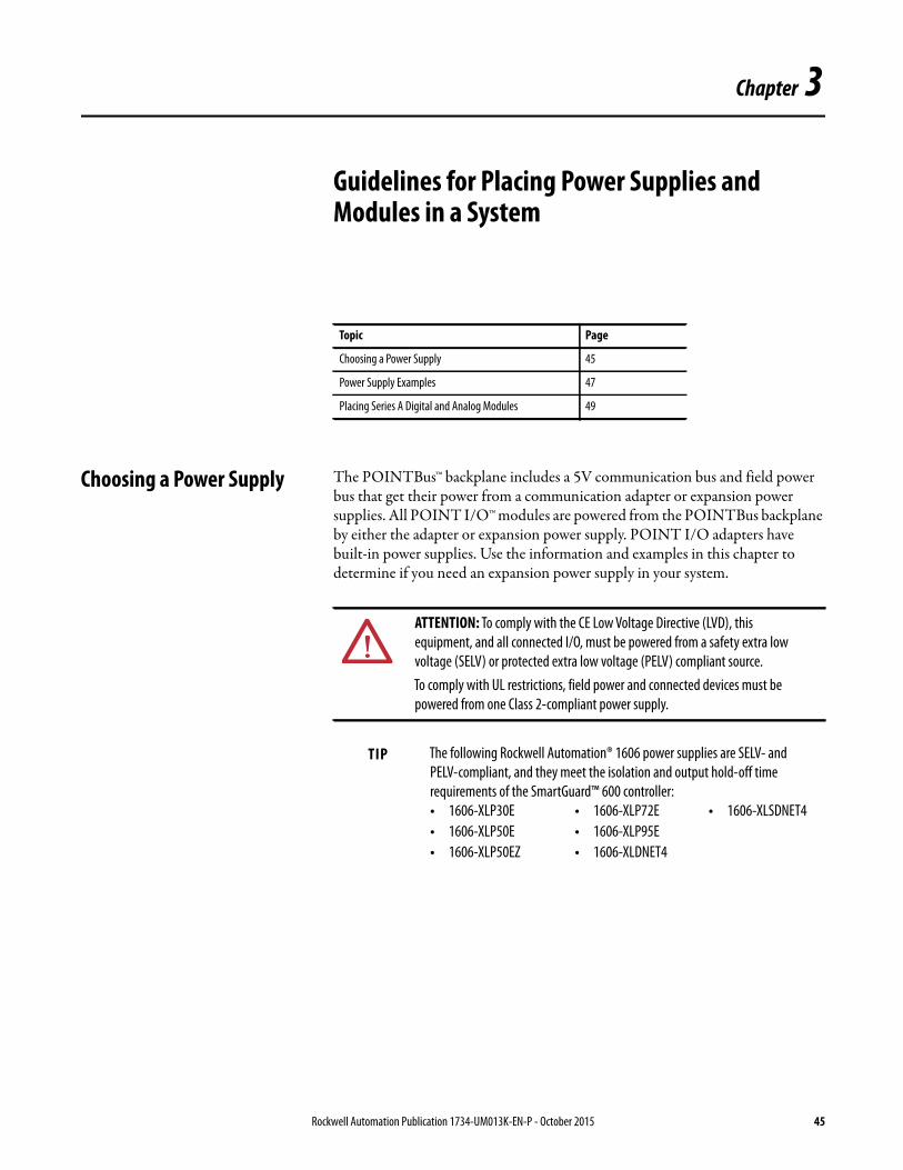
Topic Page
Choosing a Power Supply 45
Power Supply Examples 47
Placing Series A Digital and Analog Modules 49
ATTENTION: To comply with the CE Low Voltage Directive (LVD), this
equipment, and all connected I/O, must be powered from a safety extra low
voltage (SELV) or protected extra low voltage (PELV) compliant source.
To comply with UL restrictions, field power and connected devices must be
powered from one Class 2-compliant power supply.
TIP The following Rockwell Automation® 1606 power supplies are SELV- and
PELV-compliant, and they meet the isolation and output hold-off time
requirements of the SmartGuard™ 600 controller:
• 1606-XLP30E
• 1606-XLP50E
• 1606-XLP50EZ
• 1606-XLP72E
• 1606-XLP95E
• 1606-XLDNET4
• 1606-XLSDNET4
Rockwell Automation Publication 1734-UM013K-EN-P - October 2015 45

Chapter 3 Guidelines for Placing Power Supplies and Modules in a System
Follow the safety precautions that are listed in Chapter 1 and the wiring guidelines that are described in Chapter 4 before connecting a power supply to the system.
To choose which types of power supplies meet your requirements, you must consider the power consumption requirements for the 5V and 24V bus when designing a POINTBus backplane.
Choose from these power supplies for the POINTBus backplane and field power:
• Use the 1734-EP24DC expansion power supply to provide an additional 10 A of 24V DC field power and provide an additional 1.3 A of 5V current to the I/O modules to the right of the power supply.
• Use the 1734-FPD field power distributor to provide an additional 10 A of 24V DC field power, and to pass through all POINT I/O backplane signals including the 5V bus supplied to the left, without providing additional POINTBus backplane power. This action lets you isolate field power segments.
• Use the 1734-EPAC expansion power supply (for standard I/O modules) to provide an additional 10 A of 120/240V AC field power and provide an additional 1.3 A of 5V current to the I/O modules to the right of the power supply.
See the POINT I/O Selection Guide, publication 1734-SG001, for more information on compatible power supplies.
IMPORTANT If you use the 1734-EPAC expansion power supply to the left of the POINT
Guard I/O™ modules, you must use a 1734-FPD field power distributor or
1734-EP24DC expansion power supply. These distributors are used to isolate
POINT Guard I/O field power from the AC field supply.
5V POINTBus power is required to establish and maintain communication
(connection) between the module and the controller.
46 Rockwell Automation Publication 1734-UM013K-EN-P - October 2015

Guidelines for Placing Power Supplies and Modules in a System Chapter 3
Power Supply Examples Use these valid power-supply example configurations to help you understand various combinations of power supplies that can fit your system:
• Example 1: Isolating Field Power Segments on page 47• Example 2: POINT Guard I/O Used with AC I/O Modules on page 48
These examples are for illustrative purposes only, to help you understand various power sourcing concepts.
Example 1: Isolating Field Power Segments
This power supply example uses a 1734-EP24DC expansion power supply and 1734-FPD field power distributor to illustrate mixing standard POINT I/O and safety POINT Guard I/O modules. The example illustrates the mixing standard while creating separate groups for input and output modules, along with digital and analog modules.
IMPORTANT • You must define the requirements for segmenting field and bus power in your application.
• POINT Guard I/O does not require separate field-bus power usage, that is, separate power supplies for the 1734-IB8S, 1734-OB8S, or 1734-IE4S modules. This step is optional.
• POINT Guard I/O does not require separate POINTBus (communication) power-supply usage, which separates it from any other POINT I/O modules, except when additional POINTBus power is required.
• Do not apply AC voltage to POINT Guard I/O modules.
Standard I/OStandard I/O
Standard I/OStandard I/O
Standard I/OStandard I/O
Standard I/O
Standard I/O
Standard I/O
Standard I/OStandard I/OStandard I/O
1734-EP24DC
1734-FPD
1734-FPD
1734-EP24DC
1734-AENT
EtherNet/IP Adapter
1734-IB8S
1734-IB8S
1734-OB8S
1734-OB8S
1734-IE4S
1734-IE4S
5V and 24V Supply for
Additional I/O
Modules (option)
5V5V 5V
Group 2 Group 3 Group 4 Group 5Group 1
24V
1734-IB8S
24V Supply for
Safety Outputs
24V Supply for
Safety
Analog Inputs
5V Supply for All Safety
Modules and 24V Supply
for Safety Inputs
5V and 24V Supply for
Standard I/O
Modules
24V24V 24V 24V
Rockwell Automation Publication 1734-UM013K-EN-P - October 2015 47

Chapter 3 Guidelines for Placing Power Supplies and Modules in a System
Example 2: POINT Guard I/O Used with AC I/O Modules
This power supply example uses 1734-EP24DC and 1734-EPAC expansion power supplies to illustrate mixing standard POINT I/O and safety POINT Guard I/O modules, while creating a separate power group for AC I/O modules.
Standard I/OStandard I/O
Standard I/O
Standard I/O
Standard I/O
1734-EPAC
1734-EP24DC
1734-AENT
EtherNet/IP Adapter
Standard I/OStandard I/O
Standard I/O
Standard I/O
1734-IB8S
1734-IB8S
1734-OB8S
1734-OB8S
1734-IE4S
5V 5V
Group 2Group 1
120V
AC
5V and 120V AC
Supply
5V and 24V Supply for
Safety Inputs and Outputs
5V and 24V Supply
for Standard I/O
Modules
24V24V
5V
Group 3
48 Rockwell Automation Publication 1734-UM013K-EN-P - October 2015

Guidelines for Placing Power Supplies and Modules in a System Chapter 3
Placing Series A Digital and Analog Modules
Always install modules in accordance with their specified operating temperature ratings, as listed in Appendix, and provide a minimum of 5.08 cm (2 in.) clearance above the modules.
• Limit ambient temperature operation to 40 °C (104°F) if Series A POINT Guard I/O modules are used without 1734-CTM spacer modules.
Figure 22 - Placing Series A Digital Modules for up to 40 °C (104 °F) Operation
• In any system where you have any Series A POINT Guard I/O modules, use a 1734-CTM spacer between every POINT Guard I/O module with ambient operation between 40 °C (104 °F) and 55 °C (131 °F).
Insert a 1734-CTM module next to each standard I/O module (gray) if the thermal dissipation specification of that module is more than 1 W.
Figure 23 - Placing Series A Digital and Analog Modules for Operation from 40 °C (104 °F)…55°C (131°F) max.
• When using Series A POINT Guard I/O modules in your system limit the power supply to 24V DC maximum, to limit the Series A POINT Guard I/O thermal dissipation of the module.
See System Temperature Derating When a 1734-IE4S Module Is Used on page 186 for more information.
ATTENTION: Vertical orientation requires careful attention to design details
and panel layout so that all modules in the stack must operate within their
rated operating temperature range.
For Vertical installations, be sure that 1734-CTM spacer modules are installed next
to any Series A POINT Guard IO modules operating above 40 °C (104 °F) ambient.
1734-AENT
1734-IB8S/A
1734-IB8S/A
1734-OB8S/A
1734-IE4S/A
1734-IE4S/A
1734-IE4S/A
5.08 cm (2 in.)
1734-AENT
1734-IB8S/A
1734-IB8S/A
1734-OB8S/A
1734-IE4S/A
1734-IE4S/A
1734-IE4S/A
1734-CTM
5.08 cm (2 in.)
Rockwell Automation Publication 1734-UM013K-EN-P - October 2015 49

Chapter 3 Guidelines for Placing Power Supplies and Modules in a System
Placing Series B Digital Modules
Always install modules in accordance with their specified operating temperature ratings, as listed in Appendix C, and provide a minimum of 5.08 cm (2 in.) clearance above the modules.
To implement a system that contains only 1734-IB8S Series B and 1734-OB8S Series B POINT Guard I/O modules (no POINT Guard I/O Series A modules used), follow these guidelines.
• Series B POINT Guard I/O modules are used without 1734-CTM spacer modules with ambient operation up to 55 °C (131 °F). See Technical Specifications for Series B Modules for Series B POINT Guard I/O module derating requirements for every module with ambient operation between 40 °C (104 °F) and 55 °C (131 °F).
Figure 24 - Placing Series B Digital Modules for up to 55 °C (131 °F) Operation
ATTENTION: Vertical orientation requires careful attention to design details
and panel layout so that all modules in the stack operate within their rated
operating temperature range.
1734-AENT
1734-OB8S/B
1734-IB8S/B
1734-OB8S/B
1734-IB8S/B
1734-OB8S/B
1734-IB8S/B
5.08 cm (2 in.)
50 Rockwell Automation Publication 1734-UM013K-EN-P - October 2015

Chapter 4
Install the Module
Figure 25 - POINT Guard I/O™ Modules
Topic Page
Precautions 52
Install the Mounting Base 54
Connect the Module to the Mounting Base 56
Connect the Removable Terminal Block 57
Remove a Mounting Base 58
Wire Modules 58
Connection Details 61
Wiring Examples 63
Slide-in Writable Label
Insertable I/O Module
31867-M
Module Locking
Mechanism
Mounting Base
Rockwell Automation Publication 1734-UM013K-EN-P - October 2015 51

Chapter 4 Install the Module
Precautions Follow these precautions for use.
European Hazardous Location Approval
This equipment is intended for use in potentially explosive atmospheres as defined by European Union Directive 94/9/EC. The equipment has been found to comply with the Essential Health and Safety Requirements relating to the design and construction of Category 3 equipment that is intended for use in Zone 2 potentially explosive atmospheres, given in Annex II to this Directive.
Compliance with the Essential Health and Safety Requirements is assured by compliance with EN 60079-15 and EN 60079-0.
WARNING: • This equipment must be used within its specified ratings as defined by
Rockwell Automation®.
• This equipment must be mounted in an ATEX-certified enclosure with a minimum ingress protection rating of at least IP54 (as defined in IEC 60529). The equipment must also be used in an environment of not more than Pollution Degree 2 (as defined in IEC 60664-1) when applied in Zone 2 environments. The enclosure must have a tool-removable cover or door.
• Provision must be made to prevent the rated voltage from being exceeded by transient disturbances of more than 140% of the rated voltage when applied in Zone 2 environments.
• This device must be used only with ATEX-certified Rockwell Automation terminal bases.
• Do not disconnect equipment unless power has been removed or the area is known to be nonhazardous.
52 Rockwell Automation Publication 1734-UM013K-EN-P - October 2015
Install the Module Chapter 4
North American Hazardous Location Approval
Environment and Enclosure
The following information applies when operating this equipment in hazardous locations.
Informations sur l’utilisation de cet équipement en environnements dangereux.
Products marked “CL I, DIV 2, GP A, B, C, D” are suitable for use in
Class I Division 2 Groups A, B, C, D, Hazardous Locations and
nonhazardous locations only. Each product is supplied with
markings on the rating nameplate indicating the hazardous
location temperature code. When combining products within a
system, the most adverse temperature code (lowest “T” number)
may be used to help determine the overall temperature code of the
system. Combinations of equipment in your system are subject to
investigation by the local Authority Having Jurisdiction at the time
of installation.
Les produits marqués “CL I, DIV 2, GP A, B, C, D” ne conviennent qu'à une
utilisation en environnements de Classe I Division 2 Groupes A, B, C, D
dangereux et non dangereux. Chaque produit est livré avec des
marquages sur sa plaque d'identification qui indiquent le code de
température pour les environnements dangereux. Lorsque plusieurs
produits sont combinés dans un système, le code de température le plus
défavorable (code de température le plus faible) peut être utilisé pour
déterminer le code de température global du système. Les combinaisons
d'équipements dans le système sont sujettes à inspection par les
autorités locales qualifiées au moment de l'installation.
EXPLOSION HAZARD -• Do not disconnect equipment unless power
has been removed or the area is known to be nonhazardous.
• Do not disconnect connections to this equipment unless power has been removed or the area is known to be nonhazardous. Secure any external connections that mate to this equipment by using screws, sliding latches, threaded connectors, or other means provided with this product.
• Substitution of components may impair suitability for Class I, Division 2.
• If this product contains batteries, they must only be changed in an area known to be nonhazardous.
RISQUE D’EXPLOSION – • Couper le courant ou s'assurer que l'environnement
est classé non dangereux avant de débrancher l'équipement.
• Couper le courant ou s'assurer que l'environnement est classé non dangereux avant de débrancher les connecteurs. Fixer tous les connecteurs externes reliés à cet équipement à l'aide de vis, loquets coulissants, connecteurs filetés ou autres moyens fournis avec ce produit.
• La substitution de composants peut rendre cet équipement inadapté à une utilisation en environnement de Classe I, Division 2.
• S'assurer que l'environnement est classé non dangereux avant de changer les piles.
ATTENTION: This equipment is intended for use in a Pollution Degree 2 industrial environment, in overvoltage Category II
applications (as defined in IEC 60664-1), at altitudes up to 2000 m (6562 ft) without derating.
This equipment is not intended for use in residential environments and may not provide adequate protection to radio
communication services in such environments.
This equipment is supplied as open-type equipment. It must be mounted within an enclosure that is suitably designed for those
specific environmental conditions that will be present and appropriately designed to prevent personal injury resulting from
accessibility to live parts. The enclosure must have suitable flame-retardant properties to prevent or minimize the spread of flame,
complying with a flame spread rating of 5VA or be approved for the application if non-metallic. The interior of the enclosure must be
accessible only by the use of a tool. Subsequent sections of this publication may contain additional information regarding specific
enclosure type ratings that are required to comply with certain product safety certifications.
In addition to this publication, see the following:
• Industrial Automation Wiring and Grounding Guidelines, publication 1770-4.1, for additional installation requirements.
• NEMA Standard 250 and IEC 60529, as applicable, for explanations of the degrees of protection provided by enclosures.
Rockwell Automation Publication 1734-UM013K-EN-P - October 2015 53

Chapter 4 Install the Module
Preventing Electrostatic Discharge
Mount the Module
To mount the module, you must install the mounting base, connect the module to the mounting base, and then connect the removable terminal block.
Install the Mounting Base
The mounting base assembly (catalog number 1734-TB or 1734-TBS) consists of a mounting base and a removable terminal block. Alternatively, you can use the POINT I/O™ one-piece mounting base (catalog number 1734-TOP, 1734-TOPS, 1734-TOP3, or 1734-TOP3S).
ATTENTION: This equipment is sensitive to electrostatic discharge, which can
cause internal damage and affect normal operation. Follow these guidelines
when you handle this equipment:
• Touch a grounded object to discharge potential static.
• Wear an approved grounding wriststrap.
• Do not touch connectors or pins on component boards.
• Do not touch circuit components inside the equipment.
• Use a static-safe workstation, if available.
• Store the equipment in appropriate static-safe packaging when not in use.
IMPORTANT Follow these guidelines when installing a module:
• Use the module in an environment that is within the general specifications.
• Use the module in an enclosure rated at IP54 (IEC60529) or higher.
• Use DIN rail that is 35 mm (1.38 in.) wide to mount the terminal base in the control panel.
• Place other heat sources an appropriate distance away from the module to maintain ambient temperatures around the module below specified maximums.
• You can mount your module horizontally or vertically.
IMPORTANT You need two mounting base assemblies for each POINT Guard I/O™ module.
Do not use 1734-TB3 or 1734-TB3S mounting base assemblies.
54 Rockwell Automation Publication 1734-UM013K-EN-P - October 2015

Install the Module Chapter 4
Follow these steps to install the mounting base.
1. Position the mounting base as shown in the illustration below step 2.
2. Slide the mounting base down, allowing the interlocking side pieces to engage the adjacent module, power supply, or adapter.
3. Press firmly to seat the mounting base on the DIN rail until the mounting base snaps into place.
See the terminal base installation instructions for detailed information on installation and removal. Always follow instructions and torque specifications in terminal base installation instructions. See Additional Resources on page 13 for terminal base installation publications.
TIP In high vibration environments, install slide locks to prevent movement of the
mounting base along the DIN rail.
Slide the mounting base to let the interlocking side pieces engage the adjacent module or adapter.
31868-M
Rockwell Automation Publication 1734-UM013K-EN-P - October 2015 55

Chapter 4 Install the Module
Connect the Module to the Mounting Base
Install the module before or after installing the mounting base.
1. Using a screwdriver, rotate the keyswitches on the mounting base clockwise until the number required for the type of module aligns with the notch in the base.
Monitor which mounting base gets installed on the left and right of each module.
2. Verify the DIN-rail (orange) locking screw is in the horizontal position, noting that you cannot insert the module if the mounting-base locking mechanism is unlocked.
3. Insert the module straight down into the two side-by-side mounting bases and press to secure, locking the module into place.
WARNING: When you insert or remove the module while backplane power is
on, an electrical arc can occur. This arc could cause an explosion in hazardous
location installations. Be sure that power is removed or the area is
nonhazardous before proceeding.
Repeated electrical arcing causes excessive wear to contacts on both the module
and its mating connector. Worn contacts can create electrical resistance that can
affect module operation.
Cat. No. Key 1 (left) Key 2 (right)
1734-IB8S 8 1
1734-OB8S 8 2
1734-IE4S 8 3
Mounting Base Assembly
Keyswitch
Locking Mechanism
56 Rockwell Automation Publication 1734-UM013K-EN-P - October 2015

Install the Module Chapter 4
Connect the Removable Terminal Block
If a removable terminal block (RTB) is supplied with your mounting base assembly, you must remove it by pulling up on the RTB handle. This action lets you remove and replace the base as necessary without removing any of the wiring.
To reinsert the RTB, follow these directions.
1. Insert the RTB end opposite the handle into the base unit, noting that this end has a curved section that engages with the mounting base.
2. Rotate the terminal block into the mounting base until it locks itself in place.
3. If an I/O module is installed, snap the RTB handle into place on the module.
WARNING: When you connect or disconnect the removable terminal block
(RTB) with field-side power applied, an electrical arc can occur. This arc could
cause an explosion in hazardous location installations. Be sure that power is
removed or the area is nonhazardous before proceeding.
Rockwell Automation Publication 1734-UM013K-EN-P - October 2015 57
Chapter 4 Install the Module
Remove a Mounting Base
To remove a mounting base, you must remove any installed module and the module that is installed in the base to the right. If the mounting base has a removable terminal base (RTB), unlatch the RTB handle on the I/O module and pull on the handle to remove the RTB.
1. To remove it from the base, pull up on the I/O module.
2. Remove the module to the right of the base you are removing, noting that the interlocking portion of the base sits under the adjacent module.
3. Use a screwdriver to rotate the orange DIN-rail locking screw on the mounting base to a vertical position, which releases the locking mechanism.
4. Lift the mounting base off the DIN rail.
Wire Modules Follow these guidelines when wiring the modules.• Do not route communication, input, or output wiring with conduit
containing high voltage. See the Industrial Automation Wiring and Grounding Guidelines, publication 1770-4.1.
• Wire correctly after confirming the signal names of all terminals.• Use shielded cable for analog and tachometer inputs.• When using the sensor power supply on the 1734-IE4S module, do not
connect an external power supply to the sensor.• If you use the 1734-IE4S sensor power supply of the module to power your
input devices, you are responsible for verifying that your application operates properly with the diagnostic features of this output.
• Tighten screws for communication and I/O connectors correctly. • When using analog inputs, wire only to voltage or only to current inputs,
not both. If you mix input types it can induce noise on the input measurements.
WARNING: When you insert or remove the module while backplane power is
on, an electrical arc can occur. This arc could cause an explosion in hazardous
location installations. Be sure to remove power or that the area is nonhazardous
before proceeding.
58 Rockwell Automation Publication 1734-UM013K-EN-P - October 2015

Install the Module Chapter 4
ATTENTION: Wire the POINT Guard I/O modules properly so that 24V DC line
does not touch the safety outputs accidentally or unintentionally.
Do not connect loads beyond the rated value to safety outputs.
Wire conductors correctly and verify operation of the module before placing the
system into operation. Incorrect wiring can lead to loss of safety function.
Do not apply DC voltages exceeding the rated voltages to the module.
Do not connect a power source to the sensor power supply in the 1734-IE4S
module or you could blow an internal fuse, rendering the module inoperative.
Disconnect the module from the power supply before wiring. If wiring is performed
while power is supplied, devices that are connected to the module can operate
unexpectedly.
WARNING: If you connect or disconnect wiring while the field-side power is
on, an electrical arc can occur. This arc could cause an explosion in hazardous
location installations. Be sure that power is removed or the area is
nonhazardous before proceeding.
This equipment must be used within its specified ratings that are defined by
Rockwell Automation.
ATTENTION: This product is grounded through the DIN rail to chassis ground.
Use zinc plated yellow-chromate steel DIN rail to assure proper grounding. The
use of other DIN rail materials (for example, aluminum or plastic) that can
corrode, oxidize, or are poor conductors, can result in improper or intermittent
grounding. Secure DIN rail to mounting surface approximately every 200 mm
(7.8 in.) and use end-anchors appropriately.
Rockwell Automation Publication 1734-UM013K-EN-P - October 2015 59

Chapter 4 Install the Module
Terminal Layout
Figure 26, Figure 27, and Figure 28 on page 61 show the field wiring connections for the POINT Guard I/O modules.
Figure 26 - 1734-IB8S Field Connections
Figure 27 - 1734-OB8S Field Connections
I0 I1 I4 I5
I2 I3 I6 I7
COM COM COM COM
TO T1M T2 T3M
0
2
4
6
1
3
5
7
0
2
4
6
1
3
5
7
Where:T0 = Test Output 0T1M = Test Output 1 with MutingT2 = Test Output 2T3M = Test Output 3 with MutingI0…I7 = Inputs 0…7COM = Supply Common
1734-TOP and 1734-TB Bases Shown
O0 O1 O4 O5
O2 O3 O6 O7
COM COM COM COM
COM COM COM COM
0
2
4
6
1
3
5
7
0
2
4
6
1
3
5
7
1734-TOP and 1734-TB Bases Shown
Where:O0…O7 = Safety Outputs 0…7COM = Supply Common
60 Rockwell Automation Publication 1734-UM013K-EN-P - October 2015

Install the Module Chapter 4
Figure 28 - 1734-IE4S Field Connections
Connection Details See the tables that show input device connection methods and their safety categories.
V0 V1 V2 V3
I0 I1 I2 I3
COM COM COM COM
COM COM COM COM
S0 S1 S2 S3
S0 S1 S2 S3
1734-TOP3 Base Shown
Where:V0…V3 = Voltage inputs 0…3I0…I3 = Current inputs 0…3COM = Supply CommonS0…S3 = Sensor power terminals
Connected Device Test Pulse from Test Output
Connection Schematic Diagram Safety Category
Push Button No Connect the push button between 24V DC and I0.
1
Yes Connect the push button between I0 and T0. T0 must be configured as test pulse.
2
I0 I1 T0 T1
24V DC
I0 I1 T0 T1
Rockwell Automation Publication 1734-UM013K-EN-P - October 2015 61

Chapter 4 Install the Module
Emergency stop button
Door monitoring switch
No Connect the devices between T0 and I0 and I1, noting that T0 is configured for 24V power supply.
3
Connect the devices between 24V DC and I0 and I1.
Yes Connect the device between I0 and T0, and I1 and T1.
4
Light Curtain Yes Connect the OSSD1 and OSSD2 to I0 and I1, respectively. Connect the 24V power supply commons.
3 or 4 based on light curtain being used
Connected Device Test Pulse from Test Output
Connection Schematic Diagram Safety Category
I0 I1 T0 T1
I0 I1 T0 T1
24V DC
I0 I1 T0 T1
I0 I1 T0 T1In -
24V DC
Com
OSSD2
OSSD1
62 Rockwell Automation Publication 1734-UM013K-EN-P - October 2015

Install the Module Chapter 4
Wiring Examples Read this section for examples of wiring by application. See catalog number details for the appropriate module.
Emergency Stop Dual-channel Devices
This example shows wiring and controller configuration when using a digitalPOINT Guard I/O module with an emergency stop button and gate monitoring switch that have dual-channel contacts. When used in combination with the programs in a safety controller, this wiring is safety Category 4 (emergency stop button) and safety Category 3 (gate monitoring switch).
Figure 29 - POINT Guard I/O Module Wiring (dual-channel contacts)
Controller Configuration
Parameter Name Configuration Setting
Safety Input 0 Safety Input 0 Channel Mode Test Pulse from Test Output
Safety Input 0 Test Source Test Output 0
Dual-channel Safety Input 0/1 Mode Dual-channel Equivalent
Dual-channel Safety Input 0/1 Discrepancy Time 100 ms (application dependent)
Safety Input 1 Safety Input 1 Channel Mode Test Pulse from Test Output
Safety Input 1 Test Source Test Output 1
Safety Input 2 Safety Input 2 Channel Mode Safety Input
Safety Input 2 Test Source Test Output 2
Dual-channel Safety Input 2/3 Mode Dual-channel Equivalent
Safety Input 3 Safety Input 3 Channel Mode Safety Input
Safety Input 3 Test Source Test Output 3
Test Output 0 Test Output 0 Mode Pulse Test Output
Test Output 1 Test Output 1 Mode Pulse Test Output
Test Output 2 Test Output 2 Mode Power Supply Output
Test Output 3 Test Output 3 Mode Power Supply Output
IO
I2
COM
COM
TO
TO
I1
I3
COM
COM
T1M
T1M
I4
I6
COM
COM
T2
T2
I5
I7
COM
COM
T3M
T3M
1734-TB, 1734-TOP, 1734-TOP3 Bases Shown
Only with the 1734-TOP3 base.
Rockwell Automation Publication 1734-UM013K-EN-P - October 2015 63

Chapter 4 Install the Module
Single-channel Safety Contactor
This example shows wiring and controller configuration when using a digital POINT Guard I/O module with one safety contactor.
When used in combination with the programs of the safety controller, this circuit configuration is safety Category 2.
Figure 30 - POINT Guard I/O Module Wiring (single safety contact)
COM COM COMCOM
COM COM COMCOM
00 01 04 05
02 03 06 07
K1K1
M
Where:O0…O7 = Safety OutputsCOM = Common
Controller Configuration
Parameter Name Configuration Setting
Safety Output 0 Safety Output 0 Point Mode Safety Pulse Test
Point Operation Type Single Channel
64 Rockwell Automation Publication 1734-UM013K-EN-P - October 2015

Install the Module Chapter 4
Dual-channel Safety Contactors
This example shows wiring and controller configuration when using a digital POINT Guard I/O module with redundant safety contactors.
When used in combination with the programs of the safety controller, this circuit configuration is safety Category 4. Additional wiring, such as monitoring feedback, can be required to achieve safety Category 4.
Figure 31 - POINT Guard I/O Module Wiring (redundant safety contacts)
COM COM COMCOM
COM COM COMCOM
00 01 04 05
02 03 06 07
K1K1
K2K2
M
Where:O0…O7 = Safety OutputsCOM = Common
Controller Configuration
Parameter Name Configuration Setting
Safety Output 0 Safety Output 0 Point Mode Safety Pulse Test
Point Operation Type Dual-channel
Safety Output 1 Safety Output 1 Point Mode Safety Pulse Test
Rockwell Automation Publication 1734-UM013K-EN-P - October 2015 65

Chapter 4 Install the Module
Safety Analog Input Wiring
The following sections contain important guidelines for wiring safety analog inputs and wiring examples for the 1734-IE4S module.
Guidelines for Wiring Safety Analog Inputs
Follow these guidelines when wiring your safety analog inputs.
For eight terminal connections, either the 1734-TOP or 1734-TB terminal base can be used. For all 12 terminal connections, only the 1734-TOP3 base can be used. When using a 1734-TOP3 base, both of the COM terminals and both of the Sensor Power terminals for each channel are internally connected. The FE terminal connection that is shown on the diagrams represents a grounding lug on the panel or terminal connection to the DIN rail.
If the sensor has a digital output for use with Tachometer mode, it must be either a push-pull type output or have appropriate pull-up or pull-down resistors for NPN or PNP sensors. The analog input module does not provide the low impedance of these pull-up or pull-down resistors.
See Figure 44 and Figure 45 on page 73 for examples.
IMPORTANT You must verify the behavior of your 3-wire sensor to make sure that if it loses
its ground connection, the signal is 0 (safe state) at the module input when the
fault occurs.
IMPORTANT To obtain SIL 3, Cat. 3 or Cat.4, you must make sure that the analog input
signals cannot short together or that the two sensors are installed to provide
signals that are offset from one another. When the module is configured as the
source for sensor power, a short-circuit is detected at powerup (Cat. 2).
However, when an external power supply is used, another means must detect
this fault.
66 Rockwell Automation Publication 1734-UM013K-EN-P - October 2015

Install the Module Chapter 4
Safety Analog Input Wiring Examples
Figure 32 - 2-wire Current (4…20 mA) Sensor (SIL2 or SIL 3)
Figure 33 - 3-wire Voltage or Tachometer Sensor (SIL 2)
Follow the Guidelines for Wiring Safety Analog Inputs on page 66.
V0 V1 V2 V3
I0 I1 I2 I3
COM COM COM COM
S0
FE
S1 S2 S3
SIL2 or SIL 32-wire Sensor
1734-TB Terminal Bases
Signal (I)
+24V
Cable Shield
V0 V1 V2 V3
I0 I1 I2 I3
COM COM COM COM
S0
FE
S1 S2 S3
For analog voltage-output sensors, the signal levels for operation for the application must be outside the signal level when the signal is not present, for example, when the wire is broken.
See Figure 44 and Figure 45 on page 73 for tachometer wiring detail.
SIL 23-wire Sensor
1734-TB Terminal Bases
Signal (V)
+24V
Cable Shield
Signal Return
Rockwell Automation Publication 1734-UM013K-EN-P - October 2015 67

Chapter 4 Install the Module
Figure 34 - 3-wire Current Sensor (SIL 2)
Figure 35 - 4-wire Voltage or Tachometer Sensor (SIL 2)
Follow the Guidelines for Wiring Safety Analog Inputs on page 66.
V0 V1 V2 V3
I0 I1 I2 I3
COM COM COM COM
S0
FE
S1 S2 S3
For 0…20 mA analog current-output sensors, the signal levels for operation for the application must be outside the signal level when the signal is not present, for example, when the wire is broken.
SIL 23-wire Sensor
1734-TB Terminal Bases
Signal (I)
+24V
Cable Shield
Signal Return
FE
V0 V1 V2 V3
I0 I1 I2 I3
COM COM COM COM
COM COM COM COM
S0 S1 S2 S3
S0 S1 S2 S3
Signal Return and Common are at the same potential.
See Figure 44 and Figure 45 on page 73 for tachometer wiring detail.
SIL 24-wire Sensor
1734-TOP3 Terminal Bases
Signal (V)
+24V
Cable Shield
Signal Return
Common
68 Rockwell Automation Publication 1734-UM013K-EN-P - October 2015

Install the Module Chapter 4
Figure 36 - 4-wire Current Sensor (SIL 2)
Figure 37 - 2-wire Current (4…20 mA) Sensor (SIL 3)
Follow the Guidelines for Wiring Safety Analog Inputs on page 66.
FE
V0 V1 V2 V3
I0 I1 I2 I3
COM COM COM COM
COM COM COM COM
S0 S1 S2 S3
S0 S1 S2 S3
Signal Return and Common are at the same potential.
SIL 24-wire Sensor
1734-TOP3 Terminal Bases
Signal (I)
+24V
Cable Shield
Signal Return
Common
V0 V1 V2 V3
I0 I1 I2 I3
COM COM COM COM
S0
FE
S1 S2 S3
FE
Field sensors are monitoring the same signal in a redundant configuration.
You must configure a safety deadband between the two signals to achieve SIL 3.
SIL 22-wire Sensor
1734-TB Terminal Bases
Signal (I)
+24V
Cable Shield
Cable Shield
+24V
SIL 22-wire Sensor
Signal (I)
Rockwell Automation Publication 1734-UM013K-EN-P - October 2015 69
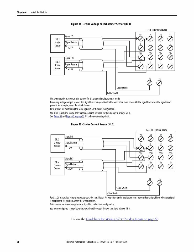
Chapter 4 Install the Module
Figure 38 - 3-wire Voltage or Tachometer Sensor (SIL 3)
Figure 39 - 3-wire Current Sensor (SIL 3)
Follow the Guidelines for Wiring Safety Analog Inputs on page 66.
V0 V1 V2 V3
I0 I1 I2 I3
COM COM COM COM
S0
FE
S1 S2 S3
FE
This wiring configuration can also be used for SIL 2 redundant Tachometer mode.
For analog voltage-output sensors, the signal levels for operation for the application must be outside the signal level when the signal is not present, for example, when the wire is broken.
Field sensors are monitoring the same signal in a redundant configuration.
You must configure a safety discrepancy deadband between the two signals to achieve SIL 3.
SIL 23-wire Sensor
1734-TB Terminal Bases
Signal (V)
+24V
Cable Shield
Cable Shield
+24V
SIL 23-wire Sensor
Signal (V)
Signal Return
Signal Return
See Figure 44 and Figure 45 on page 73 for tachometer wiring detail.
V0 V1 V2 V3
I0 I1 I2 I3
COM COM COM COM
S0
FE
S1 S2 S3
FE
For 0…20 mA analog current-output sensors, the signal levels for operation for the application must be outside the signal level when the signal is not present, for example, when the wire is broken.
Field sensors are monitoring the same signal in a redundant configuration.
You must configure a safety discrepancy deadband between the two signals to achieve SIL 3.
SIL 23-wire Sensor
1734-TB Terminal Bases
Signal (I)
+24V
Cable Shield
Cable Shield
+24V
SIL 23-wire Sensor
Signal (I)
Signal Return
Signal Return
70 Rockwell Automation Publication 1734-UM013K-EN-P - October 2015

Install the Module Chapter 4
Figure 40 - 4-wire Voltage or Tachometer Sensor (SIL 3)
Figure 41 - 4-wire Current Sensor (SIL 3)
Follow the Guidelines for Wiring Safety Analog Inputs on page 66.
FE FE
V0 V1 V2 V3
I0 I1 I2 I3
COM COM COM COM
COM COM COM COM
S0 S1 S2 S3
S0 S1 S2 S3
This wiring configuration may also be used for SIL 2 redundant Tachometer mode.
Signal Return and Common are at the same potential.
Field sensors are monitoring the same signal in a redundant configuration.
You must configure a safety discrepancy deadband between the two signals to achieve SIL 3.
SIL 24-wire Sensor
1734-TOP3 Terminal Bases
Signal (V)
+24V
Cable Shield
Signal Return
Common
SIL 24-wire Sensor
Signal (V)
+24V
Signal Return
Common
Cable Shield
See Figure 44 and Figure 45 on page 73 for tachometer wiring detail.
FE FE
V0 V1 V2 V3
I0 I1 I2 I3
COM COM COM COM
COM COM COM COM
S0 S1 S2 S3
S0 S1 S2 S3
Signal Return and Common are at the same potential.
Field sensors are monitoring the same signal in a redundant configuration.
You must configure a safety discrepancy deadband between the two signals to achieve SIL 3.
SIL 24-wire Sensor
1734-TOP3 Terminal Bases
Signal (I)
+24V
Cable Shield
Signal Return
Common
SIL 24-wire Sensor
Signal (I)
+24V
Signal Return
Common
Cable Shield
Rockwell Automation Publication 1734-UM013K-EN-P - October 2015 71

Chapter 4 Install the Module
In the following two examples, the negative terminal of the sensor power supply and that of the 1734 terminal base COMMON must be at the same potential. Use of an external power supply limits diagnostics and increases susceptibility to noise.
Follow the Guidelines for Wiring Safety Analog Inputs on page 66.
Figure 42 - 4-wire Voltage or Tachometer Sensor (SIL 2) with External Power Supply
Figure 43 - 4-wire Current Sensor (SIL 2) with External Power Supply
IMPORTANT You are responsible for making sure that the sensor is receiving appropriate
power. Safety sensors that are not properly powered do not always deliver
accurate signals to the analog input module.
V0
DC
V1 V2 V3
I0 I1 I2 I3
COM COM COM COM
S0
FE
S1 S2 S3
+
-
Signal Return and Common are at the same potential.
1734-TB Terminal Bases
Signal (V)
+24V
Cable Shield
Signal Return4-wire Sensor
See Figure 44 and Figure 45 on page 73 for tachometer wiring detail.
V0
DC
V1 V2 V3
I0 I1 I2 I3
COM COM COM COM
S0
FE
S1 S2 S3
+
-
Signal Return and Common are at the same potential.
1734-TB Terminal Bases
Signal (V)
+24V
Cable Shield
Signal Return4-wire Sensor
72 Rockwell Automation Publication 1734-UM013K-EN-P - October 2015

Install the Module Chapter 4
Figure 44 - Safety Analog Input Wiring for Sinking Tachometer Sensor
Figure 45 - Safety Analog Input Wiring for Sourcing Tachometer Sensor
Follow the Guidelines for Wiring Safety Analog Inputs on page 66.
V0 V1 V2 V3
I0 I1 I2 I3
COM COM COM COM
COM COM COM COM
S0 S1 S2 S3
S0 S1 S2 S3
Sinking Sensor(NPN-type)
1734-TOP3 Terminal Bases
Metal Oxide or Carbon Composition
1k2W
25
20
15
10
5
0
Edge-to-edge TimeMeasured Here
1734-IE4S with Trigger = Falling Edge
Transistor Pull-down
Resistor Pull-up
Elec
tron
ics
V0 V1 V2 V3
I0 I1 I2 I3
COM COM COM COM
COM COM COM COM
S0 S1 S2 S3
S0 S1 S2 S3
1734-TOP3 Terminal BasesSourcing Sensor
(PNP-type)
Metal Oxide or Carbon Composition
1k2W
25
20
15
10
5
0
Edge-to-edge TimeMeasured Here
1734-IE4S with Trigger = Rising Edge
Resistor Pull-down
Transistor Pull-up
Elec
tron
ics
Rockwell Automation Publication 1734-UM013K-EN-P - October 2015 73

Chapter 4 Install the Module
Notes:
74 Rockwell Automation Publication 1734-UM013K-EN-P - October 2015
Chapter 5
Configure the Module in a GuardLogix Controller System
Setting Up the Module When using a GuardLogix® controller on an EtherNet/IP network, configure the POINT Guard I/O™ modules by using the Logix Designer application.
At the bottom of each dialog box, click Help for information about how to complete entries in that dialog box. At the bottom of warning dialog boxes, click Help for information about that specific error.
When first setting up your POINT Guard I/O modules on an EtherNet/IP network, perform the following steps.
1. Add and Configure the Ethernet Bridge Module.
2. Add and Configure the 1734 Ethernet Adapter.
3. Add and Configure Safety Digital Input Modules.
4. Add and Configure Safety Digital Output Modules.
5. Add and Configure Safety Analog Input Modules
Topic Page
Setting Up the Module 75
Add and Configure the Ethernet Bridge Module 76
Add and Configure the 1734 Ethernet Adapter 76
Add and Configure Safety Digital Input Modules 79
Add and Configure Safety Digital Output Modules 88
Add and Configure Safety Analog Input Modules 93
Values and States of Tags 102
Configure Safety Connections 104
Configuration Ownership 105
Saving and Downloading the Module Configuration 106
IMPORTANT You must configure each point that will be used as a safety input or output.
By default, all safety input and output points are disabled.
TIP If you need an add-on profile, visit the My Support website at
http://support.rockwellautomation.com/ControlFLASH/LogixProfiler.asp.
Rockwell Automation Publication 1734-UM013K-EN-P - October 2015 75

Chapter 5 Configure the Module in a GuardLogix Controller System
Add and Configure the Ethernet Bridge Module
Follow this procedure to add and configure the Ethernet bridge module. In this example, we use a 1756 GuardLogix controller.
1. From the I/O Configuration tree, right-click 1756 Backplane, 1756-Axx, and choose New Module.
2. In the Select Modules dialog box, check Communication and Allen-Bradley®.
3. Choose an Ethernet module from the list and click Create.
In this example, we chose the 1756-EN2T bridge module. These module revisions support CIP Safety.
4. Specify the properties for the new module.
a. In the Name field of the New Module dialog box, type the name of the Ethernet bridge module.
b. In the Description field, type an optional description.c. In the IP Address field, type the IP address.d. In the Slot field, choose the slot number.
Cat. No. Compatible Major Revision
1756-EN2F 1 or later
1756-EN2T 1 or later
1756-ENBT 3 or later
1756-EN2TR 3 or later
1756-EN3TR 3 or later
1768-ENBT 3 or later
76 Rockwell Automation Publication 1734-UM013K-EN-P - October 2015

Configure the Module in a GuardLogix Controller System Chapter 5
5. To edit the Module Definition, click Change.a. In the Revision fields, choose the major and minor revisions.b. From the Electronic Keying pull-down menu, choose the appropriate
keying method.
6. Click OK.
The I/O Configuration tree displays the Ethernet connection.
Add and Configure the 1734 Ethernet Adapter
1. Right-click the Ethernet connection and choose New Module.
2. On the Select Module dialog box, check Communication and Allen-Bradley.
3. Choose an Ethernet adapter from the list and click Create.
Choose Description
Compatible Module Allows a module to determine whether it can emulate the module that is defined in the configuration that is sent from the controller.
Disable Keying None of the parameters in the physical module and module that is configured in the software must match. Do not choose Disable Keying.
Exact Match All parameters must match or the inserted module rejects a connection to the controller.
Rockwell Automation Publication 1734-UM013K-EN-P - October 2015 77
Chapter 5 Configure the Module in a GuardLogix Controller System
4. Specify the general properties of the Ethernet adapter.
a. In the Name field of the New Module dialog box, type the name of the 1734 Ethernet adapter.
b. In the Description field, type a description, if desired.c. In the IP Address field, type the IP address.
5. To edit the Ethernet Adapter Module Definition, click Change..
a. In the Revision fields, choose the major and minor revisions.
b. From the Electronic Keying pull-down menu, choose the appropriate keying method.
IMPORTANT 1734-AENT adapter firmware must be major revision 3 or later to
support POINT Guard I/O modules.
Choose Description
Exact Match Module and type series must exactly match or the module is rejected by the controller.
Compatible Module Controller checks module type and revision for compatibility. Compatible modules that match or are newer are accepted.
Disable Keying Controller checks module type, but accepts any version. Do not choose Disable Keying.
78 Rockwell Automation Publication 1734-UM013K-EN-P - October 2015

Configure the Module in a GuardLogix Controller System Chapter 5
c. From the Connection pull-down menu, choose the appropriate connection for the 1734 Ethernet adapter.
d. From the Chassis Size pull-down menu, choose the number of POINT I/O modules that are attached to the 1734 Ethernet adapter plus 1 for the 1734 Ethernet adapter.
6. Click OK to return to the Module Properties dialog box.
7. Click OK again to apply your changes.
The I/O Configuration tree displays the 1734 Ethernet adapter.
Add and Configure Safety Digital Input Modules
To include a safety digital input module in the project, you add the module under the I/O chassis in the I/O Configuration tree. Then configure the general properties of the module, configure the digital inputs, and configure test outputs as described in the following sections.
Add the Safety Digital Input Module
To add the POINT Guard I/O safety digital input module, follow these steps.
Choose Description
Listen Only Read or verify standard digital I/O data only, but does not control the modules. (When you have multiple controllers, one controller is used to control and the other controllers are used to monitor.)
None The adapter makes a direct connection to each of the module’s listed under the 1734-AENT adapter in the I/O Configuration tree.
Rack Optimization
Standard digital I/O data is collected into one rack image. POINT specialty, analog, or safety (POINT Guard I/O) modules do not use rack optimization.
TIP If there are no standard digital I/O modules in your POINT I/O™
system, choose None.
IMPORTANT Do not count terminal bases. Enter only the number of physical modules that
are installed, plus 1 for the adapter. This number must match exactly. You
cannot enter a higher number anticipating future expansion.
Each POINT Guard module that you configure can consume up to 2 connections
of the 20 connection limit within the 1734-AENT or 1734-AENTR modules. Be
sure that you are aware of and design your POINT system with these limits in
mind.
Rockwell Automation Publication 1734-UM013K-EN-P - October 2015 79

Chapter 5 Configure the Module in a GuardLogix Controller System
1. Right-click the POINT I/O Chassis and choose New Module.
2. From the Select Module dialog box, check Digital and Allen-Bradley.
3. Select an input module and click Create.
4. Specify the general properties of the module.
a. In the Name field of the New Module dialog box, type a unique name for the input module.
80 Rockwell Automation Publication 1734-UM013K-EN-P - October 2015

Configure the Module in a GuardLogix Controller System Chapter 5
b. From the Module Number pull-down menu, choose a unique module number that corresponds to the position of the module in the chassis.
c. In the Description field, type a description, if desired.d. In the Safety Network Number field, use the default setting.
For a detailed explanation of the safety network number (SNN), see the GuardLogix Controller Systems Safety Reference Manuals that are listed in the Additional Resources on page 13. However, in most cases, you use the default that is provided by the Logix Designer application.
The purpose of the safety network number (SNN) is to make sure that every module in a system can be uniquely identified. We suggest that all safety modules on a network have the same SNN, to make documentation easier. During configuration, the Logix Designer application defaults an SSN of a safety device to match the SNN of the lowest safety node on each network.
5. To edit the Module Definition, click Change.
a. In the Series field, choose the input series letter of the module.b. In the Revision fields, choose the input revision number of the module.c. From the Electronic Keying pull-down menu, choose the appropriate
keying method for the input module.
d. From the Configured By pull-down menu, choose the appropriate method by which this module is configured.
Choose Description
Exact Match All parameters must match or the inserted module rejects a connection to the controller.
Compatible Module
Allows an I/O module to determine whether it can emulate the module that is defined in the configuration that is sent from the controller.
Choose Description
This Controller This selection directs the controller to configure the module.
External Means This selection directs the controller to establish a safety input connection only, and the controller doesn’t configure the module or control the Test Outputs.
Rockwell Automation Publication 1734-UM013K-EN-P - October 2015 81

Chapter 5 Configure the Module in a GuardLogix Controller System
e. From the Input Data pull-down menu, choose Safety or None.
f. From the Output Data pull-down menu, choose from the following options.
Choose Description
Safety These tags are created for the target module:• RunMode for module mode• ConnectionFaulted for communication status• Safety Data for safety inputs from the module
Choose Description
None Results in an input only connection to the module. Inputs and status are read, but no outputs are written. You can still use the test outputs as pulse test outputs or a power supply. If you are not controlling the test outputs of the module via application logic, this is the recommended setting.
Test(1)
(1) To have this choice from the pull-down menu, you must choose ‘This Controller’ from the Configured By pull-down
menu.
Creates these tags to enable application logic control of the test outputs on the module. This selection allows the test outputs to be used as standard outputs and muting outputs.
IMPORTANT When test outputs are configured as standard outputs, they
must not be used for safety purposes.
82 Rockwell Automation Publication 1734-UM013K-EN-P - October 2015

Configure the Module in a GuardLogix Controller System Chapter 5
g. From the Input Status pull-down menu, choose from the following options.
h. From the Data Format pull-down menu, use the default ‘Integer’.
Choose Description
None There are no status tags.
Pt. Status There is one status tag for each input point.
Combined Status - Muting
• One BOOL tag represents an AND of the status bits for all input points. For example, if any input channel has a fault, this bit goes LO.(1)
• One BOOL tag represents the Input Power Status (error bit) from the input assembly.
• A muting status tag for test output T1 and T3.
(1) When using combined status, use explicit messaging to read individual point status for diagnostic purposes.
Pt. Status - Muting There is a muting status tag for test output T1 and T3 with point status for each input point.
Pt. Status-Muting-Test Output
• Status tags for each of the input points. • Muting status tag for test output T1 and T3.• Status tags for each of the test outputs.
Rockwell Automation Publication 1734-UM013K-EN-P - October 2015 83
Chapter 5 Configure the Module in a GuardLogix Controller System
6. Click OK to return to the Module Properties dialog box.
7. Click OK again to apply your changes.
The I/O Configuration tree displays the module.
Configure the Safety Digital Inputs
To configure the safety digital inputs, follow this procedure.
1. From the Module Properties dialog box, click the Input Configuration tab.
2 3 4
5
6
7
84 Rockwell Automation Publication 1734-UM013K-EN-P - October 2015
Configure the Module in a GuardLogix Controller System Chapter 5
2. Assign the Point Operation Type.
When you choose Equivalent or Complementary, you must also assign a Discrepancy Time.
A discrepancy time setting of 0 ms means that the channels in a dual configuration can be discrepant for an infinite amount of time without a fault being declared.
For a discrepancy time setting of 0 ms, the evaluated status of the inputs still goes to the safe state due to a ‘cycle inputs’ required condition. However, with a 0 ms discrepancy time setting, a fault is not declared.
A ‘cycle inputs’ required condition occurs when one input terminal goes from its normal Active->Inactive->Active state while the other input terminal remains in its normal Active state. Even though no fault is declared, the inputs must be cycled through the safe state before the evaluated status of the inputs can return to the Active state. When in a ‘cycle inputs’ required condition, the logical state does not necessarily match the voltage at the terminals.
Choose Description
Single Inputs are treated as single channels.
Dual-channel safety inputs can be configured as two individual single channels. This configuration does not affect pulse testing because it is handled on an individual channel basis.
IMPORTANT: Use single-channel mode when you intend to use the GuardLogix safety application instructions.
Equivalent Inputs are treated as a dual-channel pair. The channels must match within the discrepancy time or an error is generated.
Complementary Inputs are treated as a dual-channel pair. They must be in opposite states within the discrepancy time or an error is generated.
IMPORTANT Configuring discrepancy time on safety I/O modules masks input
discrepancies that are detected by the controller safety instructions.
The controller reads status to obtain this fault information.
Rockwell Automation Publication 1734-UM013K-EN-P - October 2015 85

Chapter 5 Configure the Module in a GuardLogix Controller System
3. Assign the Point Mode.
4. Assign a Test Source for each safety input on the module you want to pulse test.
5. Assign the Input Delay Time, Off -> On (0…126 ms, in increments of 6 ms).
Filter time is for OFF to ON transition. Input must be high after input delay has elapsed before it is set logic 1. This delay time is configured per channel with each channel tuned to match the characteristics of the field device, for maximum performance.
6. Assign the Input Delay Time, Off -> On (0…126 ms, in increments of 6 ms).
Filter time is ON to OFF transition. Input must be low after input delay has elapsed before it is set logic 0. This delay time is configured per channel with each channel tuned to match the characteristics of the field device, for maximum performance.
Choose Description
Not Used The input is disabled. If 24V is applied to the input terminal it remains logic 0.
Safety Pulse Test Pulse testing is performed on this input circuit. A test source on the POINT Guard I/O module must be used as the 24V source for this circuit. The test source is configured by using the test source pull-down menu. The pulse test detects shorts to 24V and channel-to-channel shorts to other inputs.
Safety A safety input is connected but there is no requirement for the POINT Guard I/O module to perform a pulse test on this circuit. An example is a safety device that performs its own pulse tests on the input wires, such as a light curtain.
Standard A standard device, such as a reset switch, is connected. This point cannot be used in dual-channel operation.
Choose Description
None
If pulse testing is performed on an input point, then the test source that is sourcing the 24V for the input circuit must be selected.
If the incorrect test source is entered, the result is pulse test failures on that input circuit.
Test Output 0
Test Output 1(1)
Test Output 2
Test Output 3(1)
(1) Test Output 1 and 3 incorporate optional muting functionality.
86 Rockwell Automation Publication 1734-UM013K-EN-P - October 2015
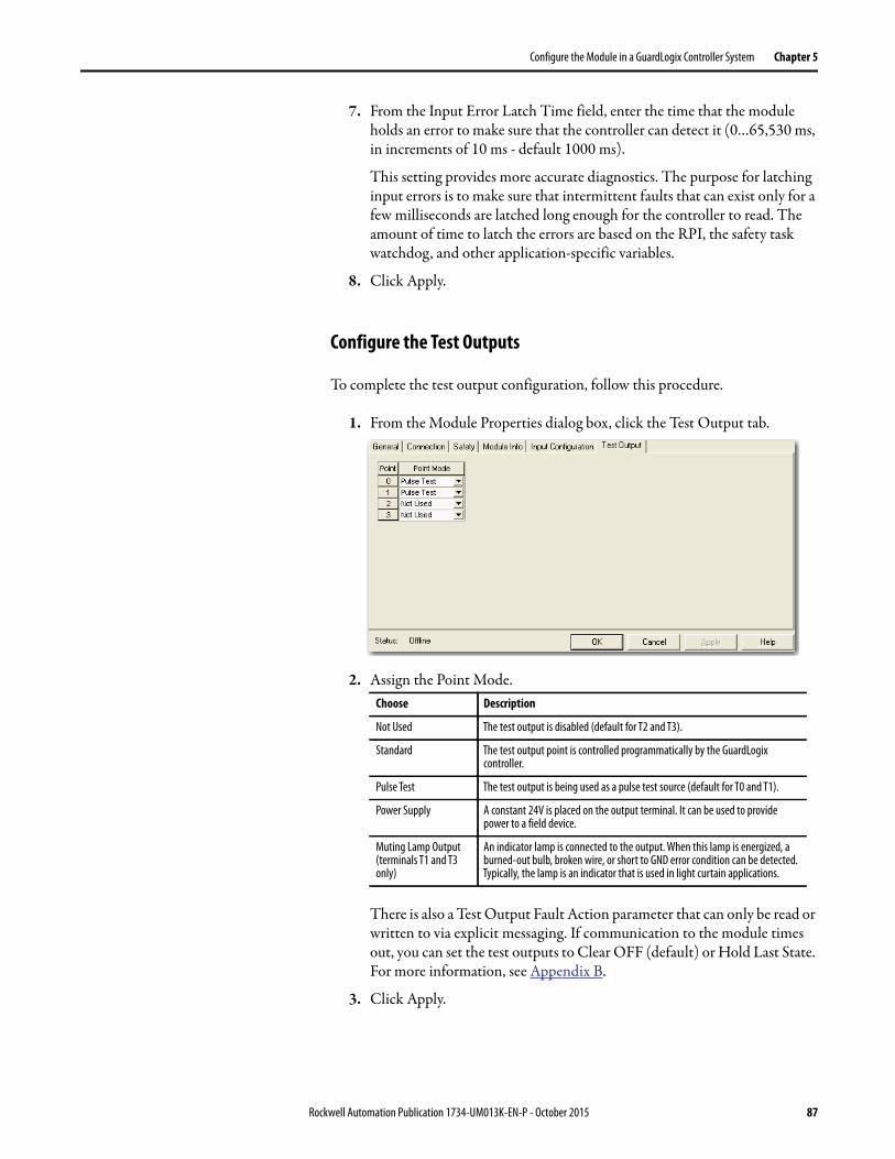
Configure the Module in a GuardLogix Controller System Chapter 5
7. From the Input Error Latch Time field, enter the time that the module holds an error to make sure that the controller can detect it (0…65,530 ms, in increments of 10 ms - default 1000 ms).
This setting provides more accurate diagnostics. The purpose for latching input errors is to make sure that intermittent faults that can exist only for a few milliseconds are latched long enough for the controller to read. The amount of time to latch the errors are based on the RPI, the safety task watchdog, and other application-specific variables.
8. Click Apply.
Configure the Test Outputs
To complete the test output configuration, follow this procedure.
1. From the Module Properties dialog box, click the Test Output tab.
2. Assign the Point Mode.
There is also a Test Output Fault Action parameter that can only be read or written to via explicit messaging. If communication to the module times out, you can set the test outputs to Clear OFF (default) or Hold Last State. For more information, see Appendix B.
3. Click Apply.
Choose Description
Not Used The test output is disabled (default for T2 and T3).
Standard The test output point is controlled programmatically by the GuardLogix controller.
Pulse Test The test output is being used as a pulse test source (default for T0 and T1).
Power Supply A constant 24V is placed on the output terminal. It can be used to provide power to a field device.
Muting Lamp Output (terminals T1 and T3 only)
An indicator lamp is connected to the output. When this lamp is energized, a burned-out bulb, broken wire, or short to GND error condition can be detected. Typically, the lamp is an indicator that is used in light curtain applications.
Rockwell Automation Publication 1734-UM013K-EN-P - October 2015 87
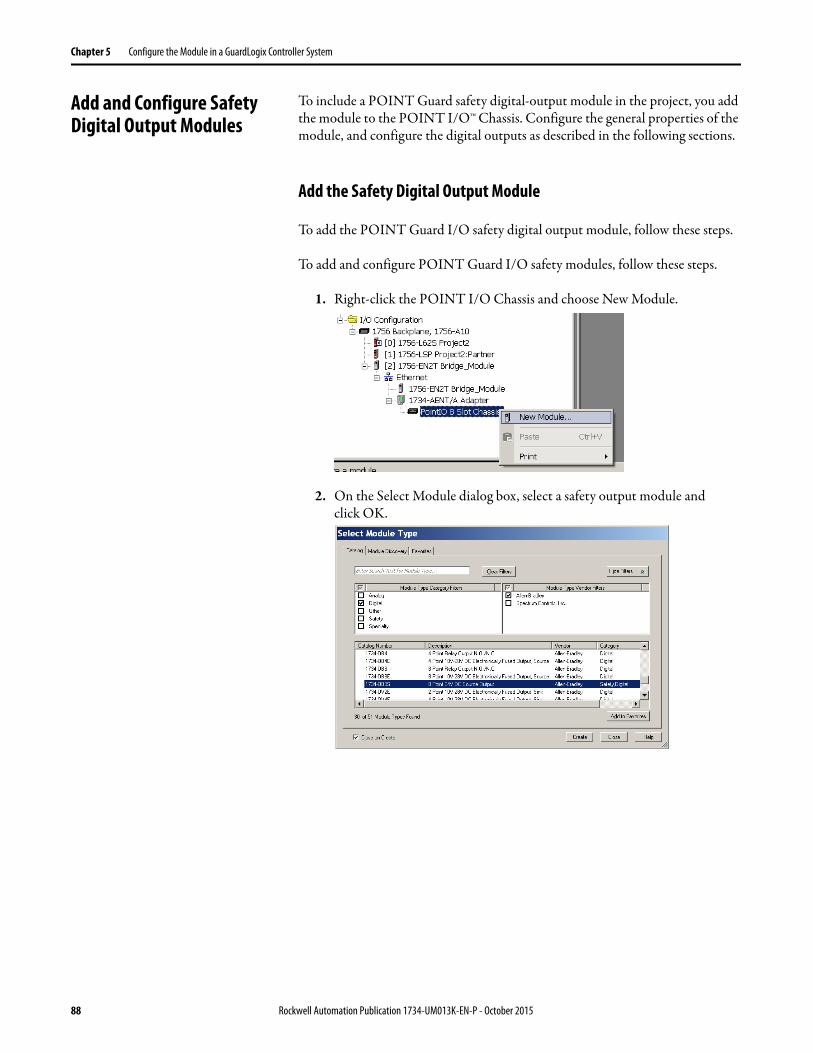
Chapter 5 Configure the Module in a GuardLogix Controller System
Add and Configure Safety Digital Output Modules
To include a POINT Guard safety digital-output module in the project, you add the module to the POINT I/O™ Chassis. Configure the general properties of the module, and configure the digital outputs as described in the following sections.
Add the Safety Digital Output Module
To add the POINT Guard I/O safety digital output module, follow these steps.
To add and configure POINT Guard I/O safety modules, follow these steps.
1. Right-click the POINT I/O Chassis and choose New Module.
2. On the Select Module dialog box, select a safety output module and click OK.
88 Rockwell Automation Publication 1734-UM013K-EN-P - October 2015
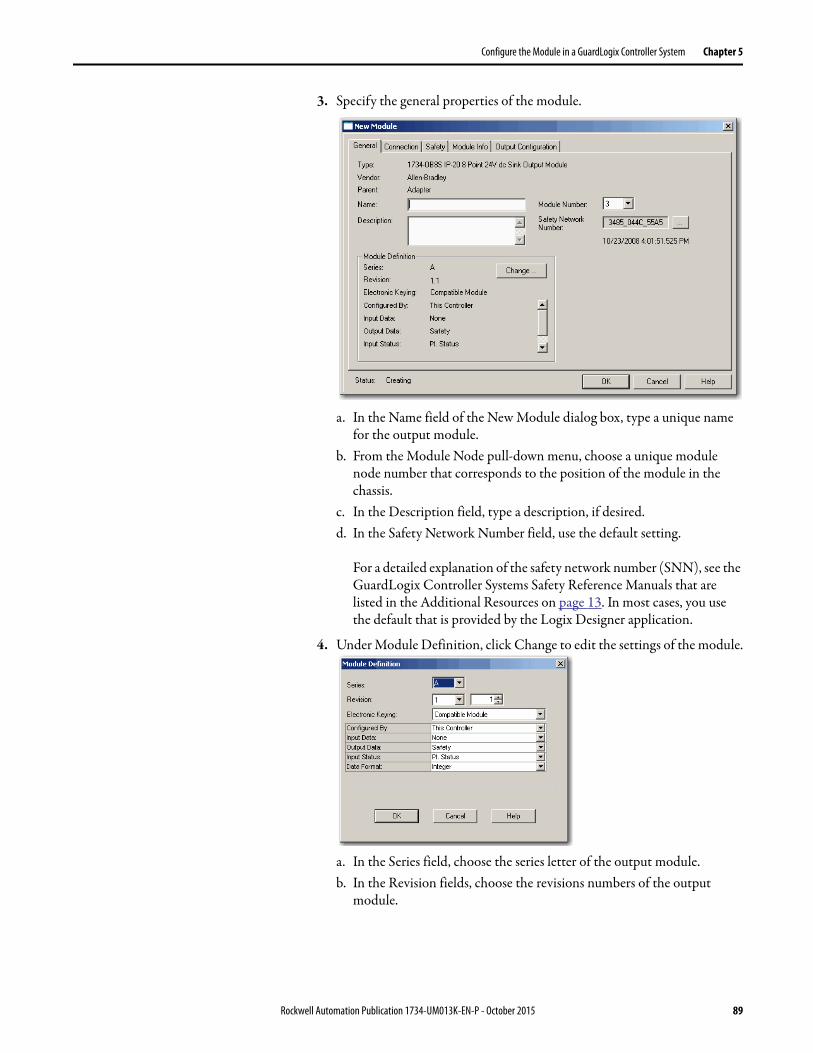
Configure the Module in a GuardLogix Controller System Chapter 5
3. Specify the general properties of the module.
a. In the Name field of the New Module dialog box, type a unique name for the output module.
b. From the Module Node pull-down menu, choose a unique module node number that corresponds to the position of the module in the chassis.
c. In the Description field, type a description, if desired.d. In the Safety Network Number field, use the default setting.
For a detailed explanation of the safety network number (SNN), see the GuardLogix Controller Systems Safety Reference Manuals that are listed in the Additional Resources on page 13. In most cases, you use the default that is provided by the Logix Designer application.
4. Under Module Definition, click Change to edit the settings of the module.
a. In the Series field, choose the series letter of the output module.b. In the Revision fields, choose the revisions numbers of the output
module.
Rockwell Automation Publication 1734-UM013K-EN-P - October 2015 89

Chapter 5 Configure the Module in a GuardLogix Controller System
c. From the Electronic Keying pull-down menu, choose the appropriate keying method from the following options.
d. From the Configured By pull-down menu, choose the method by which this module is configured.
e. From the Input Data pull-down menu, choose None.None is the only valid selection, as this module is an output-only safety module.
f. From the Output Data pull-down menu, choose from the following:
Choose Description
Exact Match All parameters must match or the inserted module rejects a connection to the controller.
Compatible Module Lets an I/O module determine whether it can emulate the module that is defined in the configuration that is sent from the controller.
Choose Description
This Controller This selection directs the controller to configure and control the safety outputs.The Output Data selection is set to Safety.
External Means This selection directs the controller to establish a safety input connection only, and the controller does not configure the module or be able to control the safety outputs.The Output Data selection is set to None.
Choose Description
Safety Automatically selected when Configured By = This controller. Results in an output connection. Selecting Safety creates output tags and enables these outputs for use in the Safety Task.
None Automatically selected when Configured By = External. Selecting None results in an input only connection to the module. Status is read, but no outputs are written.
90 Rockwell Automation Publication 1734-UM013K-EN-P - October 2015
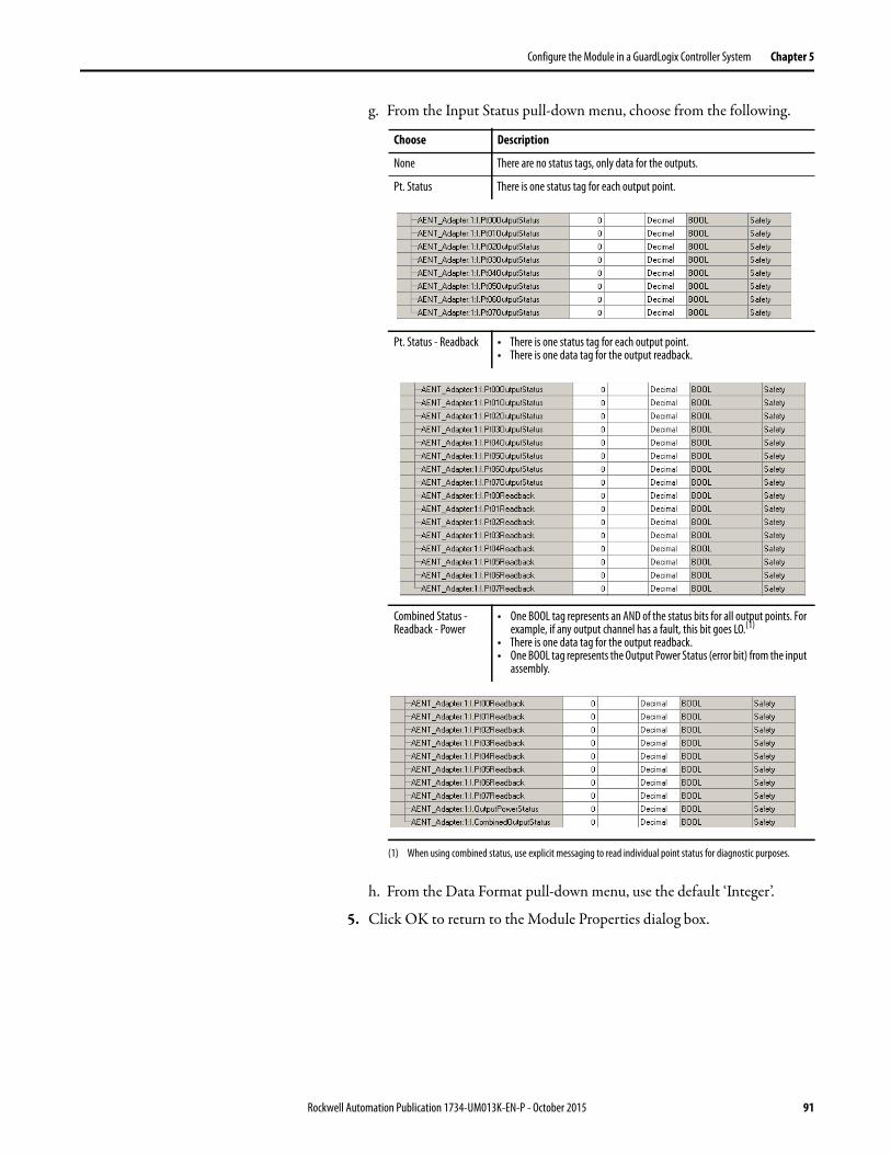
Configure the Module in a GuardLogix Controller System Chapter 5
g. From the Input Status pull-down menu, choose from the following.
h. From the Data Format pull-down menu, use the default ‘Integer’.
5. Click OK to return to the Module Properties dialog box.
Choose Description
None There are no status tags, only data for the outputs.
Pt. Status There is one status tag for each output point.
Pt. Status - Readback • There is one status tag for each output point.• There is one data tag for the output readback.
Combined Status - Readback - Power
• One BOOL tag represents an AND of the status bits for all output points. For example, if any output channel has a fault, this bit goes LO.(1)
• There is one data tag for the output readback.• One BOOL tag represents the Output Power Status (error bit) from the input
assembly.
(1) When using combined status, use explicit messaging to read individual point status for diagnostic purposes.
Rockwell Automation Publication 1734-UM013K-EN-P - October 2015 91

Chapter 5 Configure the Module in a GuardLogix Controller System
6. Click OK again to apply your changes.
The I/O Configuration tree displays the 1734-OB8S module.
Configure the Safety Digital OutputsTo configure the safety digital outputs, follow this procedure.
1. From the Module Properties dialog box, click the Output Configuration tab.
2. Assign the Point Operation Type.
3. Assign the Point Mode.
Choose Description
Single The output is treated as one channel.
Dual (default) The POINT Guard I/O module treats the outputs as a pair. It always sets them HI or LO as a matched pair. Safety logic must set both of these outputs ON or OFF simultaneously or the module declares a channel fault.
Choose Description
Not Used The output is disabled.
Safety The output point is enabled and does not perform a pulse test on the output.
Safety Pulse Test
The output point is enabled and performs a pulse test on the output. When the output is energized, the output pulses low briefly. The pulse test detects whether the output is functioning properly.
92 Rockwell Automation Publication 1734-UM013K-EN-P - October 2015

Configure the Module in a GuardLogix Controller System Chapter 5
4. In the Output Error Latch Time field, enter the time that the module holds an error to make sure that the controller can detect it (0…65,530 ms, in increments of 10 ms - default 1000 ms).This action provides more accurate diagnostics. The purpose for latching output errors is to make sure that intermittent faults that can exist only for a few milliseconds are latched long enough for the controller to read. The amount of time to latch the errors is based on the RPI, the safety task watchdog, and other application-specific variables.
5. Click Apply.
Add and Configure Safety Analog Input Modules
To include a POINT Guard safety analog input module in the project, you add the module to the POINT I/O™ Chassis, configure the general properties of the module, and configure the analog inputs as described in the following sections.
Add the Safety Analog Input Module
Follow these steps to add the POINT Guard I/O safety analog input module.
1. Right-click the POINT I/O Chassis and choose New Module.
2. From the Select Module dialog box, select an analog input module and click Create.
Rockwell Automation Publication 1734-UM013K-EN-P - October 2015 93
Chapter 5 Configure the Module in a GuardLogix Controller System
3. Specify the general properties of the module.
a. In the Name field of the New Module dialog box, type a unique name for the analog input module.
b. From the Module Number pull-down menu, choose a unique module number that corresponds to the position of the module in the chassis.
c. In the Description field, type a description, if desired.d. In the Safety Network Number field, use the default setting.
For a detailed explanation of the safety network number (SNN), see the GuardLogix Controller Systems Safety Reference Manuals that are listed in the Additional Resources on page 13. In most cases, you use the default that is provided by the Logix Designer application.
The safety network number (SNN) is a unique number that identifies a safety subnet. We suggest that all safety modules on a network have the same SNN, to make documentation easier. During configuration, the Logix Designer application defaults the SNN of a safety device to match the SNN of the lowest safety node on the network.
4. To open the Module Definition dialog box, click Change.
a. In the Series field, choose the series letter of the analog input module.b. In the Revision fields, choose the revision number of the module.
94 Rockwell Automation Publication 1734-UM013K-EN-P - October 2015

Configure the Module in a GuardLogix Controller System Chapter 5
c. From the Electronic Keying pull-down menu, choose the appropriate keying method for the input module.
d. From the Configured By pull-down menu, choose the appropriate method by which this module is configured.
e. From the Input Data pull-down menu, choose Safety.f. From the Output Data pull-down menu, choose from the following.
g. From the Process Data pull-down menu, choose from the following.
h. From the Data Format pull-down menu, use the default ‘Integer’.
5. Click OK to return to the Module Properties dialog box.
6. Click OK again to apply your changes.
The I/O Configuration tree displays the 1734-IE4S module.
Choose Description
Exact Match All parameters must match or the inserted module rejects a connection to the controller.
Compatible Module
Allows an I/O module to determine whether it can emulate the module that is defined in the configuration that is sent from the controller.
Choose Description
This Controller This selection directs the controller to configure the Inputs.
External Means This selection directs the controller to establish a safety input connection only, and the controller does not configure the module.
Choose Description
None An output tag is not generated.
Safety-Tachometer This option is available when the Configured By selection is This Controller. The output tag contains data members for safety output data that is needed for Tachometer mode. If you are using Tachometer mode, you must choose this setting; otherwise, you are not be able to configure other Tachometer parameters.
Choose Description
Status The input tag contains safety analog input data from the module.
Status - Alarms These tags are created for the target module:• Safety data for individual process alarms• Safety data for safety analog inputs from the module
Status - Alarms - Faults These tags are created for the target module:• Safety data for individual process alarms• Safety data for faults• Safety data for safety analog inputs from the module
Rockwell Automation Publication 1734-UM013K-EN-P - October 2015 95

Chapter 5 Configure the Module in a GuardLogix Controller System
Configure the Safety Analog Input Channel Operation
To configure the safety analog input channels, follow this procedure.
1. From the Module Properties dialog box, click the Safety Input Configuration tab.
2. Assign the Operation Type.
3. If you chose Equivalent, you must also assign a Discrepancy Time, from 0…65,530 ms in 10 ms increments.
This measurement is the amount of time the two channels can differ from each other (larger than the deadband value) before a discrepancy error is declared. A discrepancy time setting of 0 ms means that the channels in a dual configuration can be discrepant for an infinite amount of time without a fault being declared. This setting would effectively eliminate the usefulness of dual channel mode.
4. Configure a deadband for the paired safety analog inputs.
The deadband can be any value from 0…32767 (engineering units) in increments of 1. When the paired input values exceed the deadband tolerance for longer than the Discrepancy Time, a discrepancy fault occurs.
5. If desired, configure a Channel Offset for the paired safety analog inputs.
Choose Description
Single Inputs are treated as single channels. Dual-channel safety inputs can be configured as two individual, single channels.
IMPORTANT: Use single-channel mode when you intend to use the GuardLogix safety application instructions.
Equivalent Inputs are treated as a dual-channel equivalent pair. The channels must match within the discrepancy time or an error is generated.
IMPORTANT If you are using a Dual-channel Analog (DCA) safety instruction in
your application program, you must configure the 1734-IE4S module
for single-channel operation. Analog input pairs are then evaluated
as pairs and compared to each other in the application logic.
TIP Configure a deadband value for applications that use two sensors to
measure the same variable; otherwise, spurious trips can occur.
96 Rockwell Automation Publication 1734-UM013K-EN-P - October 2015

Configure the Module in a GuardLogix Controller System Chapter 5
The channel offset can be any value from -32768…32767 (engineering units) in increments of 1. Configure an offset when differences in the sensors nominal input signals would otherwise exceed the desired deadband. The channel offset is applied from the second to the first member of the channel pair, that is, from channel 1 to channel 0 or from channel 3 to channel 2.
6. In the Input Error Latch Time field, enter the time that the module holds an error to make sure that the controller can detect it (0…65,530 ms, in increments of 10 ms - default 1000 ms).
This setting provides more accurate diagnostics. The purpose for latching input errors is to make sure that intermittent faults that can exist only for a few milliseconds are latched long enough for the controller to read. The amount of time to latch the errors must be based on the RPI, the safety task watchdog, and other application-specific variables.
7. Click Apply.
Configure the Safety Analog Inputs
To configure the analog input points, follow these steps.
1. From the Module Properties dialog box, click the Input Configuration tab.
2. Assign the Point Mode.
If the channel operation is configured as dual-channel equivalent, when you click Apply, channel 1 is set to the same value as channel 0 and channel 3 is set to the same value as channel 2.
3. Configure the module for current, voltage, or tachometer inputs.
Choose Description
Not Used The input is disabled.
Safety Safety-related analog input value
Standard Standard analog input value, not being used for a safety function
Rockwell Automation Publication 1734-UM013K-EN-P - October 2015 97

Chapter 5 Configure the Module in a GuardLogix Controller System
4. Configure an input filter.
A single-pole, anti-aliasing filter of 10 Hz is followed by a four-pole digital filter. Choose from the following available corner frequencies.• 1 Hz (recommended for Tachometer mode)• 5 Hz• 10 Hz• 50 Hz
For more information on the filter frequencies and step response, see the technical specifications for the 1734-IE4S module on page 172 or Digital Input Filter on page 32.
5. Assign High and Low Engineering scaling values for the inputs, if desired.
The valid range for both the High and Low Engineering settings is -30000…30000, in increments of 1. Scaling lets the module report in engineering units such as degrees, PSI, CFM, and percent, rather than in raw counts.
If the channel operation is configured as dual channel equivalent, when you click Apply, channel 1 is set to the same value as channel 0 and channel 3 is set to the same value as channel 2 if the channel operation is configured as dual channel equivalent.
6. To indicate how each sensor is powered, set the Sensor Power Supply value to External or Module.
Configure Safety Analog Input Alarms (optional)
TIP Set this value to Module to supply power to the sensors connected to
the POINT Guard Analog Input module. This value allows the module
to detect a loss of sensor power.
TIP If you are using a Dual-channel Analog (DCA) safety instruction in your
application program, we recommend that you do not configure these values
on the module. Instead, to facilitate troubleshooting, use the application
program to check for high and low alarm values via the Dual Channel Analog
Input instruction or other data comparison instructions.
98 Rockwell Automation Publication 1734-UM013K-EN-P - October 2015

Configure the Module in a GuardLogix Controller System Chapter 5
To configure alarms for each of the safety analog input channels, follow these steps.
1. From the Module Properties dialog box, click the Alarm tab.
2. To configure each channel, click 0, 1, 2, or 3, as appropriate.
3. To enable the alarm, check the boxes:• Enable High High - Low Low Alarms• Enable High - Low Alarms
4. Type the alarm values from -32768…32767 in the appropriate fields, following these guidelines:• The High High alarm value must be greater than or equal to the High
alarm value.• The High alarm value must be greater that the Low alarm value.• The Low Low alarm value must be less than or equal to the Low alarm
value.• These values are based on the engineering units that are configured on
page 98.
5. Configure a deadband value for the High High - Low Low alarms and High - Low alarms, if desired.
The valid range is 0…32767. The deadband lets the alarm status bit remain set, despite the alarm condition disappearing, as long as the input data remains within the deadband of the alarm. These values are based on the Engineering units that are configured on page 98.
For more information on this feature, see Process Alarms on page 33
Rockwell Automation Publication 1734-UM013K-EN-P - October 2015 99

Chapter 5 Configure the Module in a GuardLogix Controller System
Configure Tachometer Operation
You can only configure the module for tachometer operation if your Module Definition includes Output Data for Safety-Tachometer.
Follow these steps to define how the module operates in Tachometer mode.
1. From the Module Properties dialog box, click the Tachometer Configuration tab.
2. Turn Dual Low Detection ON or OFF for each channel pair.
To increase the diagnostic coverage of your speed sensing loop, you must determine whether the two tachometer sensors you are using to sense speed are shorted together. That is, you must be able to detect a channel-to-channel fault. One method is to implement two tachometer sensors so that, during normal operation, their pulse trains are never low simultaneously. When Dual Low Detection is ON, the module detects this condition as a fault. This fault indicates that the two sensors are shorted together.
To use this feature, you must use Channels 0 and 1 together, and Channels 2 and 3 together. Channels 0 and 1 have the same setting and channels 2 and 3 have the same setting.
100 Rockwell Automation Publication 1734-UM013K-EN-P - October 2015
Configure the Module in a GuardLogix Controller System Chapter 5
3. Configure the Trigger to indicate if the module channels must count pulses on the rising edge or falling edge.
When the module is configured as Dual, channels 0 and 1 have the same setting and channels 2 and 3 have the same setting.
4. Specify a tachometer Off Level in volts for each channel.
This level is the voltage at which the module considers the tachometer sensor to be OFF for tachometer speed calculation purposes.
The valid range is 0…23V in increments of 1V. The default setting of 5V must be satisfactory for a 0...24V DC signal. For a 0...5V DC signal, a setting of 1V is recommended.
See Off and On Signal Levels on page 37 for more information on the Off and On Levels.
When the module is configured as Dual Channel Equivalent, channels 0 and 1 have the same setting and channels 2 and 3 have the same setting.
5. Specify a tachometer On Level in volts for each channel.
This level is the voltage at which the module considers the tachometer sensor to be ON for tachometer speed calculation purposes
The valid range is 1…24V in increments of 1V. The default setting of 11V must be satisfactory for a 0...24V DC signal. For a 0...5V DC signal, a setting of 4V is recommended.
See Off and On Signal Levels on page 37 for more information on the Off and On Levels.
When the module is configured as dual-channel Equivalent, channels 0 and 1 have the same setting and channels 2 and 3 have the same setting. The tachometer On Level must be greater than the tachometer Off Level.
Rockwell Automation Publication 1734-UM013K-EN-P - October 2015 101

Chapter 5 Configure the Module in a GuardLogix Controller System
Values and States of Tags This table shows the values and states of the tags.
Data Description
Digital Input Data
Run ModeSTANDARD
Indicates whether consumed data is actively being updated by a device that is in one of these states:
• Run mode: 1 Idle State: 0
Connection FaultedSTANDARD
Indicates the validity of the safety connection between the safety producer and the safety consumer.
• Valid: 0 Faulted: 1
Safety Input DataSAFETY
Indicates the ON/OFF state of each input circuit.
• ON: 1 OFF: 0
Combined Safety Input StatusSAFETY
An AND of the status of all input circuits.
• All circuits are normal: 1• An error was detected in one or more input circuits: 0
Individual Safety Input StatusSAFETY
Indicates the status of each input circuit.
• Normal: 1 Fault (Alarm): 0
Combined Safety Output StatusSAFETY
An AND of the status of all safety output circuits.
• All circuits are normal: 1• An error has been detected in one or more output circuits: 0
Individual Safety Output StatusSAFETY
Indicates the status of each safety output circuit.
• Normal: 1 Fault (Alarm): 0
Muting Lamp StatusSAFETY
Indicates the status when circuits T1 and T3 are configured as the muting lamp output.
• Normal: 1 Fault (Alarm): 0
Output Readback STANDARD
Monitors the presence of 24V on the output circuit. Readback is ON (1) if 24V is on output terminal.
• ON: 1 OFF: 0
Individual Test Output StatusSTANDARD
Indicates the status of each of the test output circuits.
• Normal: 1 Fault (Alarm): 0
Input Power Error Bit
STANDARD
Indicates field power that is supplied is within specification.
• Power error: 1 Power OK: 0
Output Power Error Bit
STANDARD
Indicates field power that is supplied is within specification.
• Power error: 1 Power OK: 0
Digital Output Data
Safety Output DataSAFETY
Controls the safety output.
• ON: 1 OFF: 0
Standard Output DataSTANDARD
Controls the test output when Test Output mode is set to a standard output.
• ON: 1 OFF: 0
102 Rockwell Automation Publication 1734-UM013K-EN-P - October 2015

Configure the Module in a GuardLogix Controller System Chapter 5
Analog Input Data
Run Mode STANDARD
Indicates whether consumed data is actively being updated by a device that is in one of these states:
• Run mode: 1 Idle State: 0
Connection FaultedSTANDARD
Indicates the validity of the safety connection between the safety producer and the safety consumer.
• Valid: 0 Faulted: 1
Safety Input Data
SAFETY
Value of analog input data
Individual Safety Input Status
SAFETY
Indicates the status of each safety input circuit.
Normal: 1 Fault (Alarm): 0
Individual Status - Process AlarmsSTANDARD
Indicates whether each Safety Input Data value of a channel is between the configured High and Low Alarm values.
Normal: 1 Alarm: 0
Individual Status - Fault ReasonSTANDARD
Input Point Fault Reason
Individual HH Alarm StatusSTANDARD
Individual High High Alarm Status
Normal: 1 Alarm: 0
Individual H Alarm StatusSTANDARD
Individual High Alarm Status
Normal: 1 Alarm: 0
Individual L Alarm StatusSTANDARD
Individual Low Alarm Status
Normal: 1 Alarm: 0
Individual LL Alarm StatusSTANDARD
Individual Low Low Alarm Status
Normal: 1 Alarm: 0
Individual Tachometer OverfrequencySAFETY
When the input is configured for Tachometer mode, this data indicates an overfrequency condition; that is, when pulses are faster than 1000 Hz.
Normal: 1 Fault: 0
Individual Tachometer Under-frequencySAFETY
When the input is configured for Tachometer mode, this data indicates an under-frequency condition; that is, when pulses are slower than 1 Hz.
Normal: 1 Fault: 0
Individual Tachometer Dual LowSAFETY
Indicates that both channels are low when the input is configured for Tachometer mode.
Normal: 1 Fault: 0
Input PowerSTANDARD
Indicates that input power over- or under-range.
Normal: 1 Fault: 0
Analog Output Data Reset TachometerSAFETY
Resets a latched overfrequency condition and enables the module to begin calculating frequency again.
• No reset: 0 Reset: 1
Data Description
IMPORTANT In the previous table, ‘SAFETY’ denotes information the controller can use in
safety-related functions. ‘STANDARD’ denotes additional information that
must not be directly used for safety functions.
ATTENTION: Do not rely on data readback to detect faults. You must monitor
status bits to detect faults.
Rockwell Automation Publication 1734-UM013K-EN-P - October 2015 103
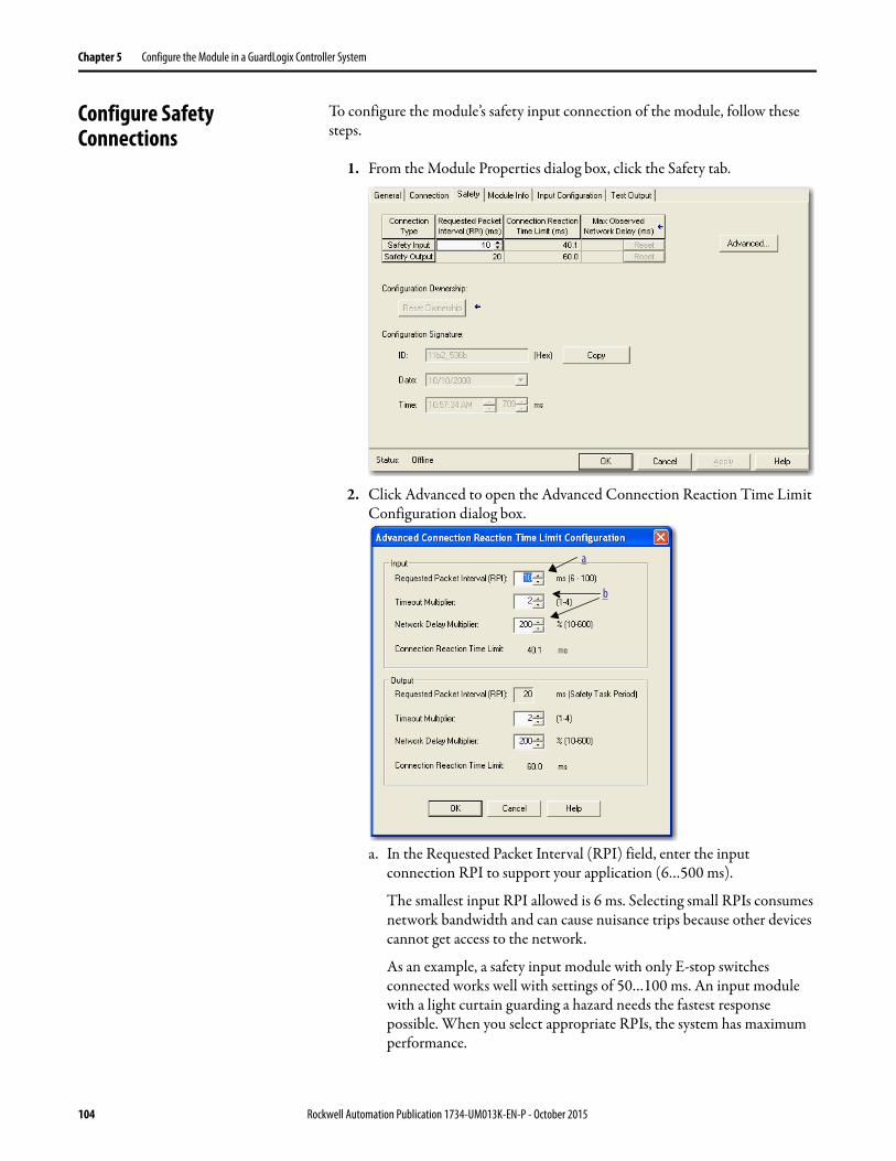
Chapter 5 Configure the Module in a GuardLogix Controller System
Configure Safety Connections
To configure the module’s safety input connection of the module, follow these steps.
1. From the Module Properties dialog box, click the Safety tab.
2. Click Advanced to open the Advanced Connection Reaction Time Limit Configuration dialog box.
a. In the Requested Packet Interval (RPI) field, enter the input connection RPI to support your application (6…500 ms).
The smallest input RPI allowed is 6 ms. Selecting small RPIs consumes network bandwidth and can cause nuisance trips because other devices cannot get access to the network.
As an example, a safety input module with only E-stop switches connected works well with settings of 50…100 ms. An input module with a light curtain guarding a hazard needs the fastest response possible. When you select appropriate RPIs, the system has maximum performance.
a
b
104 Rockwell Automation Publication 1734-UM013K-EN-P - October 2015
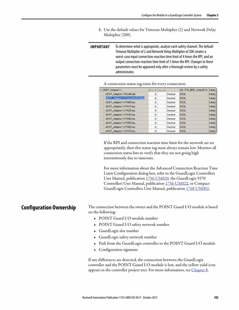
Configure the Module in a GuardLogix Controller System Chapter 5
b. Use the default values for Timeout Multiplier (2) and Network Delay Multiplier (200).
A connection status tag exists for every connection.
If the RPI and connection reaction time limit for the network are set appropriately, then this status tag must always remain low. Monitor all connection status bits to verify that they are not going high intermittently due to timeouts.
For more information about the Advanced Connection Reaction Time Limit Configuration dialog box, refer to the GuardLogix Controllers User Manual, publication 1756-UM020, the GuardLogix 5570 Controllers User Manual, publication 1756-UM022, or Compact GuardLogix Controllers User Manual, publication 1768-UM002.
Configuration Ownership The connection between the owner and the POINT Guard I/O module is based on the following:
• POINT Guard I/O module number• POINT Guard I/O safety network number• GuardLogix slot number• GuardLogix safety network number• Path from the GuardLogix controller to the POINT Guard I/O module• Configuration signature
If any differences are detected, the connection between the GuardLogix controller and the POINT Guard I/O module is lost, and the yellow yield icon appears in the controller project tree. For more information, see Chapter 8.
IMPORTANT To determine what is appropriate, analyze each safety channel. The default
Timeout Multiplier of 2 and Network Delay Multiplier of 200 creates a
worst-case input connection-reaction time limit of 4 times the RPI, and an
output connection-reaction time limit of 3 times the RPI. Changes to these
parameters must be approved only after a thorough review by a safety
administrator.
Rockwell Automation Publication 1734-UM013K-EN-P - October 2015 105
http://www.literature.rockwellautomation.com/idc/groups/literature/documents/um/1756-um022_-en-p.pdf
Chapter 5 Configure the Module in a GuardLogix Controller System
Saving and Downloading the Module Configuration
After you configure a module, it is recommended that you save and download the configuration.
If, after downloading the program, the MS and NS status indicators on the POINT Guard I/O module are not both solid green, a loss of ownership potentially occurred. A yellow yield icon in the project tree also indicates a loss of ownership. For more information, see Chapter 8.
Using ControlFLASH Software to Update POINT Guard I/O Modules
In addition, the 1734-IE4S safety analog input module requires field power to be applied while updating the firmware of the module. If a ControlFLASH update fails, check the ControlFLASH log by clicking View Log on the Update Status dialog box.
If the last message is ‘[FAILURE] Update: Error #11001: Unknown General Status error code received. GS = 0xD0, ES = 0x0001,’ verify that field power is connected to the module and restart the download.
IMPORTANT When you use ControlFLASH™ software to update a module, the software stops
a running safety I/O connection. You must inhibit I/O connections before
updating a POINT Guard I/O module.
TIP The module receives it's field power from the 24V DC connection to the power
supply feeding it, for example a 1734-AENT, 1734-FPD, or 1734-EP24DC
module. Make sure that 24V DC power is connected to these modules before
performing a flash update of the 1734-IE4S.
106 Rockwell Automation Publication 1734-UM013K-EN-P - October 2015
Chapter 6
Configure the Module for a SmartGuard Controller
This chapter provides information about how to configure a SmartGuard™ controller and POINT Guard I/O™ modules by using USB (Universal Serial Bus) connectivity. See the corresponding RSNetWorx™ for DeviceNet software help files for network-configurator operating procedures.
Topic Page
Before You Begin 108
Set the Node Address 108
Auto-addressing with a 1734-PDN Adapter 110
Set Up Your DeviceNet Network 112
Configure the POINT Guard I/O Modules 113
Configure the SmartGuard Controller 122
Save and Download Module Configuration 127
TIP For information about RSNetWorx for DeviceNet software, from the Help
menu, choose RSNetWorx Help.
Rockwell Automation Publication 1734-UM013K-EN-P - October 2015 107
Chapter 6 Configure the Module for a SmartGuard Controller
Before You Begin Confirm that you have these required items:• RSNetWorx for DeviceNet software
• RSLinx® software, version 2.51 or later• SmartGuard USB driver
The SmartGuard USB driver is already be in your RSLinx® software. If it is not, load the driver onto your computer, and be aware of the folder location as you browse to it later.
• Personal computer with a Microsoft Windows 2000, Microsoft Windows 2000 Terminal Server, or Microsoft Windows XP operating system
• 1734-PDN adapter• SmartGuard controller and POINT Guard I/O module EDS files
Load the proper electronic data sheet (EDS) files by using the EDS Hardware Installation Tool at http://www.rockwellautomation.com/resources/eds/.
Include your 1752 SmartGuard controller and POINT Guard I/O modules.
Set the Node Address Use RSNetWorx for DeviceNet software to set the node address of POINT Guard I/O modules. The module has an out-of-box preset node address of 63. We suggest that you connect and set the modules one at a time. Otherwise, the address conflicts (all of them at 63) prevents communication with some of the modules.
Cat. No. Required Version
1734-IB8S, 1734-OB8S 9 or later
1734-IE4S 10 or later
Cat. No. EDS File
1734-IB8S 0010023000F0100
1734-OB8S 001002300100100
1734-IE4S 0001002A00010100
IMPORTANT The unique identifier for a safety node is a combination of the safety network
number (SNN) and node address. When the SNN is set, the current node
address is used to generate and store this identifier in nonvolatile memory.
Once the identifier is set, for safety reasons, the node address cannot be
changed unless specific action is taken to reset the POINT Guard I/O SSN of the
module. For this reason, you are required to set the node address before the
application of an SNN.
108 Rockwell Automation Publication 1734-UM013K-EN-P - October 2015
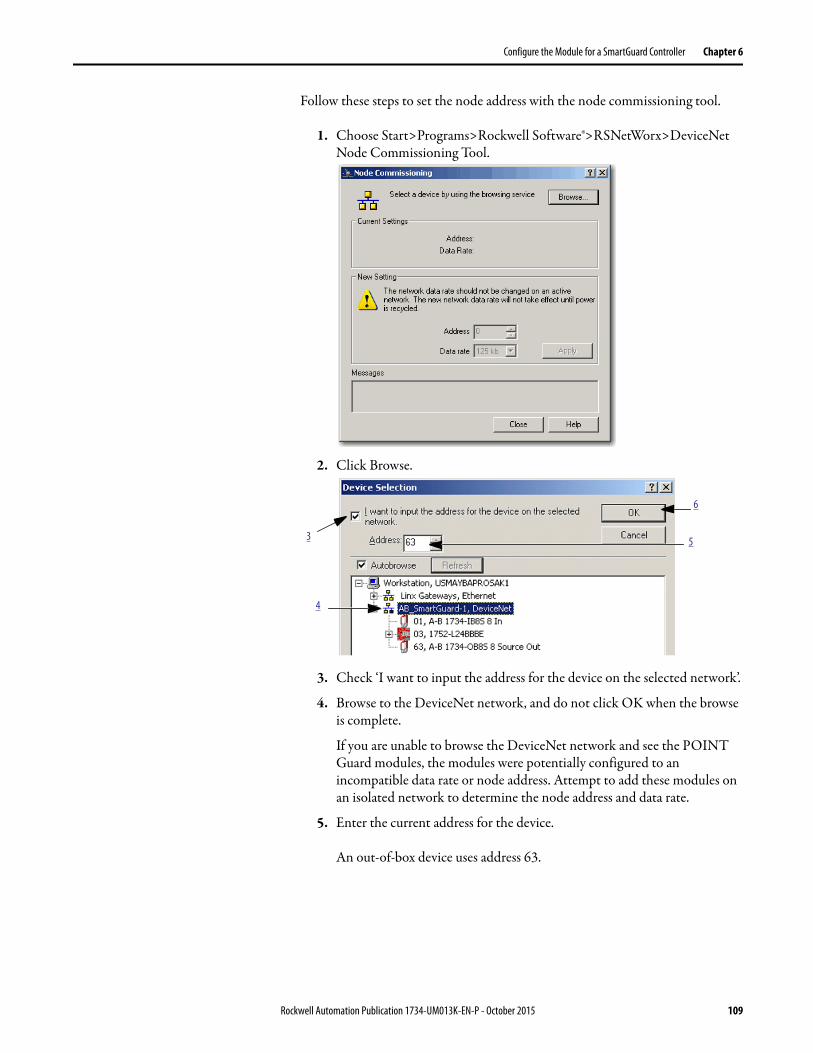
Configure the Module for a SmartGuard Controller Chapter 6
Follow these steps to set the node address with the node commissioning tool.
1. Choose Start>Programs>Rockwell Software®>RSNetWorx>DeviceNet Node Commissioning Tool.
2. Click Browse.
3. Check ‘I want to input the address for the device on the selected network’.
4. Browse to the DeviceNet network, and do not click OK when the browse is complete.
If you are unable to browse the DeviceNet network and see the POINT Guard modules, the modules were potentially configured to an incompatible data rate or node address. Attempt to add these modules on an isolated network to determine the node address and data rate.
5. Enter the current address for the device.
An out-of-box device uses address 63.
3
4
5
6
Rockwell Automation Publication 1734-UM013K-EN-P - October 2015 109

Chapter 6 Configure the Module for a SmartGuard Controller
6. Click OK
7. Enter the new address for the device.
8. Click Apply.
9. Look for confirmation in the messages section.
Auto-addressing with a 1734-PDN Adapter
With sequential auto-addressing, the leftmost node address is configured and a parameter is set in that module to automatically assign addresses to the nodes that reside to the right of the module. The leftmost node can be a POINT Guard I/O module or a standard POINT I/O module.
Follow these steps to use the auto-address feature.
1. Reset any modules that you are not sure are out-of-box.
2. Attach the first module to the 1734-PDN adapter.
3. Use the node commissioning tool to set the node address of this module.
4. Attach the additional nodes to the right of the module that is used insteps 2 and 3.
5. Perform the auto-address feature on the module that is used in steps 2 and 3.
7
8
9
110 Rockwell Automation Publication 1734-UM013K-EN-P - October 2015

Configure the Module for a SmartGuard Controller Chapter 6
A. Set the address of the leftmost I/O module.
B. When you configure the leftmost module, set Sequential AutoAddress to ‘Sequential Address’.
The module sequences the rest of the modules to its right in the group.
Rockwell Automation Publication 1734-UM013K-EN-P - October 2015 111
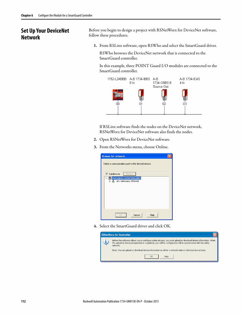
Chapter 6 Configure the Module for a SmartGuard Controller
Set Up Your DeviceNet Network
Before you begin to design a project with RSNetWorx for DeviceNet software, follow these procedures.
1. From RSLinx software, open RSWho and select the SmartGuard driver.
RSWho browses the DeviceNet network that is connected to the SmartGuard controller.
In this example, three POINT Guard I/O modules are connected to the SmartGuard controller.
If RSLinx software finds the nodes on the DeviceNet network, RSNetWorx for DeviceNet software also finds the nodes.
2. Open RSNetWorx for DeviceNet software.
3. From the Networks menu, choose Online.
4. Select the SmartGuard driver and click OK.
112 Rockwell Automation Publication 1734-UM013K-EN-P - October 2015
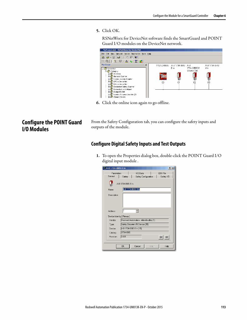
Configure the Module for a SmartGuard Controller Chapter 6
5. Click OK.
RSNetWorx for DeviceNet software finds the SmartGuard and POINT Guard I/O modules on the DeviceNet network.
6. Click the online icon again to go offline.
Configure the POINT Guard I/O Modules
From the Safety Configuration tab, you can configure the safety inputs and outputs of the module.
Configure Digital Safety Inputs and Test Outputs
1. To open the Properties dialog box, double-click the POINT Guard I/O digital input module .
Rockwell Automation Publication 1734-UM013K-EN-P - October 2015 113

Chapter 6 Configure the Module for a SmartGuard Controller
2. Click the Safety Configuration tab.
3. Double-click each set of input points to edit their configuration.
Parameter Name Value Description Default
Input Point Operation Type Single Channel Use as single channel. Single
Dual-channel Equivalent Use as dual-channel. Normal when both channels are ON or OFF.
Dual-channel Complementary Use as dual-channel. Normal when one channel is ON and the other channel is OFF.
Input Point Mode Not Used External input device is not connected. Not Used
Safety Pulse Test Use with a contact output device and in combination with a test output. When you use this setting, short-circuits between input signal lines and the power supply (positive side) and short-circuits between input signal lines can be detected.
Safety A solid-state output safety sensor is connected.
Standard A standard device, such as a reset switch, is connected.
114 Rockwell Automation Publication 1734-UM013K-EN-P - October 2015
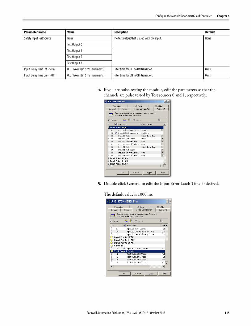
Configure the Module for a SmartGuard Controller Chapter 6
4. If you are pulse-testing the module, edit the parameters so that the channels are pulse tested by Test sources 0 and 1, respectively.
5. Double-click General to edit the Input Error Latch Time, if desired.
The default value is 1000 ms.
Safety Input Test Source None The test output that is used with the input. None
Test Output 0
Test Output 1
Test Output 2
Test Output 3
Input Delay Time Off -> On 0…126 ms (in 6 ms increments) Filter time for OFF to ON transition. 0 ms
Input Delay Time On -> Off 0…126 ms (in 6 ms increments) Filter time for ON to OFF transition. 0 ms
Parameter Name Value Description Default
Rockwell Automation Publication 1734-UM013K-EN-P - October 2015 115

Chapter 6 Configure the Module for a SmartGuard Controller
6. Double-click Test Output Points to edit their configuration.
7. Click Apply and OK.
Configure Digital Safety Outputs
1. To display the parameters for editing, double-click each group of Outputs Points.
Parameter Name Value Description Default
Test Output Mode Not Used An external device is not connected. Not Used
Standard The output is connected to a standard device.
Pulse Test A contact output device is connected. Use in combination with a safety input.
Power Supply The power supply of a Safety Sensor is connected. The voltage that is supplied to I/O power (V, G) is output from the test output terminal.
Muting Lamp Output(Terminal T1 or T3 only)
An indicator is connected and turned ON to detect broken lines in an external indicator.
Parameter Name Value Description Default
Output Point Mode Not Used An external output device is not connected. Not Used
Safety When the output is ON, the test pulse is not output (remains ON).
Safety Pulse Test When you use this function, short-circuits between output signal lines and the power supply (positive side) and short-circuits between output signal lines can be detected.
Output Point Operation Type
Single Channel Use as single channel. Dual-channel
Dual-channel Use as dual-channel. When both channels are normal, outputs can be turned ON.
Safety Output Error Latch Time
0…65,530 ms(in 10 ms increments)
Safety output errors are latched for this time. 1000 ms
116 Rockwell Automation Publication 1734-UM013K-EN-P - October 2015
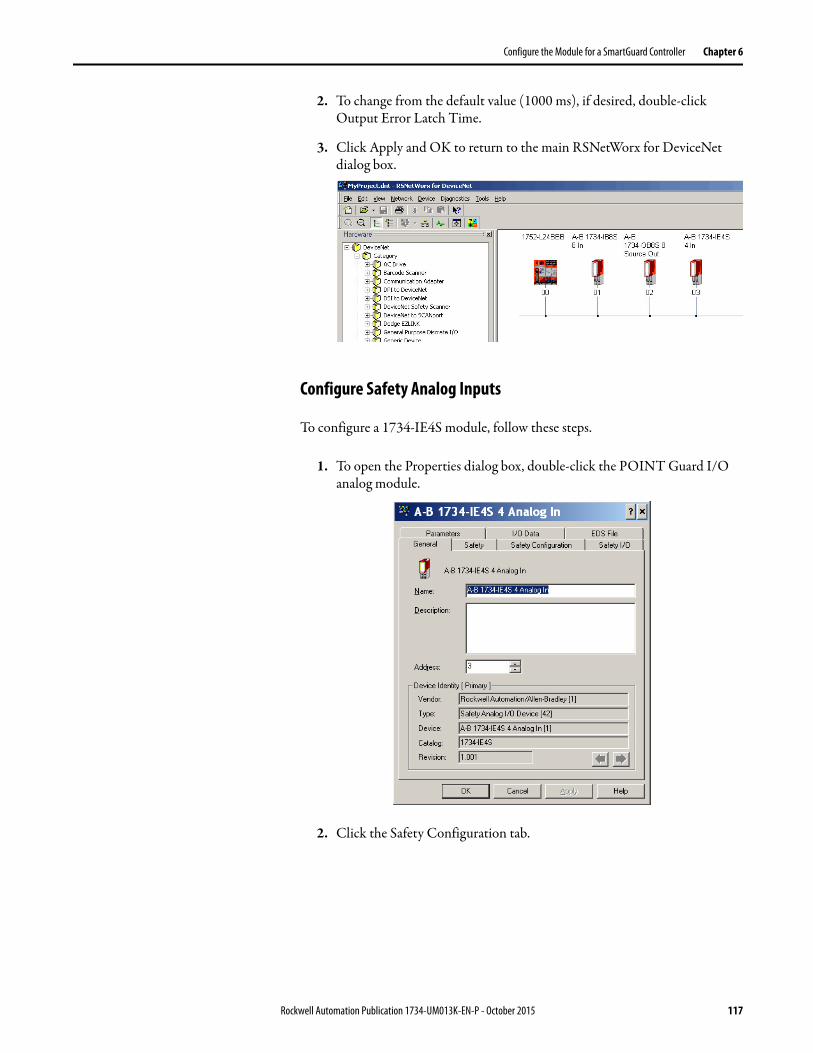
Configure the Module for a SmartGuard Controller Chapter 6
2. To change from the default value (1000 ms), if desired, double-click Output Error Latch Time.
3. Click Apply and OK to return to the main RSNetWorx for DeviceNet dialog box.
Configure Safety Analog Inputs
To configure a 1734-IE4S module, follow these steps.
1. To open the Properties dialog box, double-click the POINT Guard I/O analog module.
2. Click the Safety Configuration tab.
Rockwell Automation Publication 1734-UM013K-EN-P - October 2015 117

Chapter 6 Configure the Module for a SmartGuard Controller
3. To display the parameters for editing, double-click each group of Dual Channel Safety Inputs.
Parameter Name Value Description Default
Channel type Single Inputs are treated as single channels. Dual-channel safety inputs can be configured as two individual, single channels.
SingleEquivalent Inputs are treated as a dual-channel equivalent pair. The channels must match within the
discrepancy time or an error is generated.
Discrepancy time 0…65,530(in 10 ms increments)
When Dual Channel mode is selected, this value is the amount of time the two channels can differ from each other (larger than the deadband value) before a discrepancy error is declared. A discrepancy time setting of 0 ms means that the channels in a dual configuration can be discrepant for an infinite amount of time without a fault being declared, effectively eliminating the usefulness of dual channel mode.
100 ms
Discrepancy deadband 0…32767(in engineering units)
In Dual Channel mode, when the paired input values exceed the deadband tolerance for longer than the Discrepancy Time, a discrepancy fault occurs.
0
Channel offset -32768…32767(in engineering units)
Offset value for dual channel mode only. Configure an offset when differences in the sensors nominal input signals would otherwise exceed the desired deadband.
0
TIP Configure a deadband value for applications that use two sensors to measure the same variable; otherwise, spurious trips can occur.
118 Rockwell Automation Publication 1734-UM013K-EN-P - October 2015
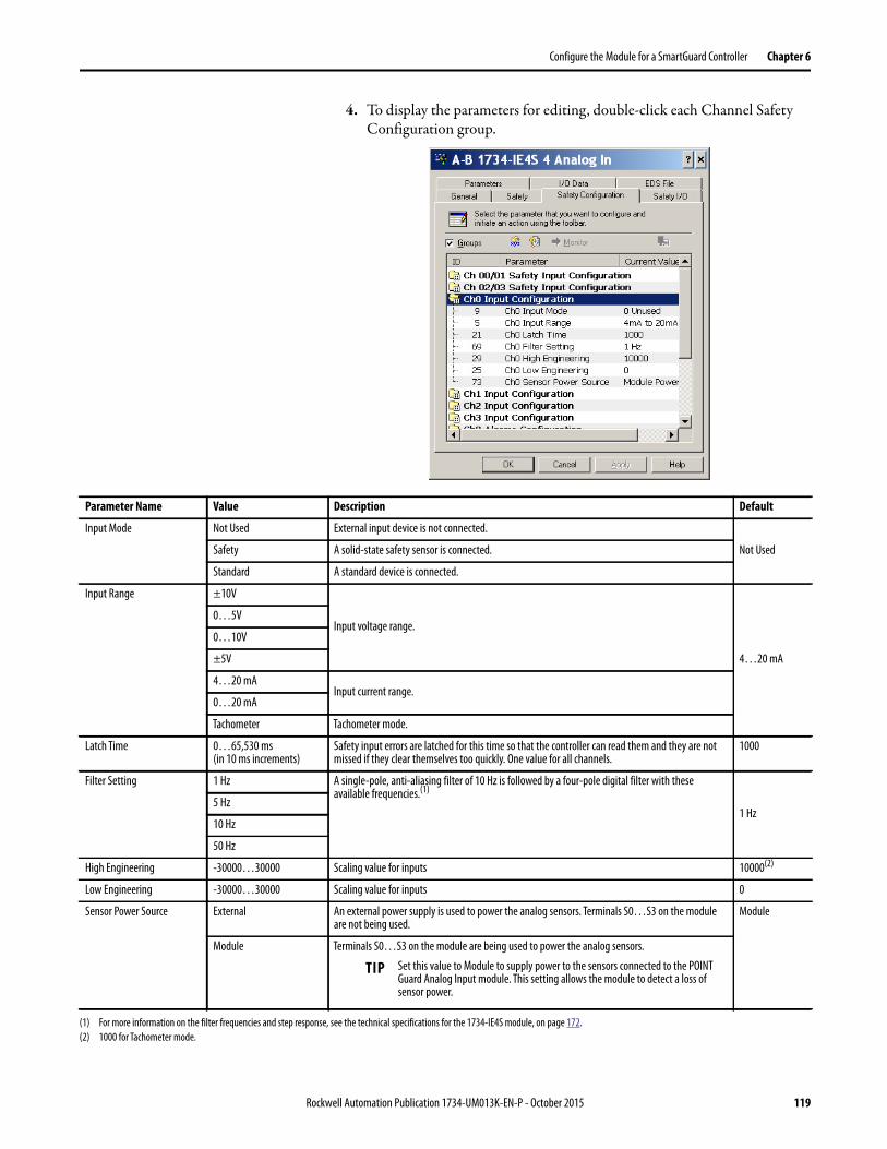
Configure the Module for a SmartGuard Controller Chapter 6
4. To display the parameters for editing, double-click each Channel Safety Configuration group.
Parameter Name Value Description Default
Input Mode Not Used External input device is not connected.
Not UsedSafety A solid-state safety sensor is connected.
Standard A standard device is connected.
Input Range ±10V
Input voltage range.
4…20 mA
0…5V
0…10V
±5V
4…20 mAInput current range.
0…20 mA
Tachometer Tachometer mode.
Latch Time 0…65,530 ms(in 10 ms increments)
Safety input errors are latched for this time so that the controller can read them and they are not missed if they clear themselves too quickly. One value for all channels.
1000
Filter Setting 1 Hz A single-pole, anti-aliasing filter of 10 Hz is followed by a four-pole digital filter with these available frequencies.(1)
1 Hz5 Hz
10 Hz
50 Hz
High Engineering -30000…30000 Scaling value for inputs 10000(2)
Low Engineering -30000…30000 Scaling value for inputs 0
Sensor Power Source External An external power supply is used to power the analog sensors. Terminals S0…S3 on the module are not being used.
Module
Module Terminals S0…S3 on the module are being used to power the analog sensors.
(1) For more information on the filter frequencies and step response, see the technical specifications for the 1734-IE4S module, on page 172.
(2) 1000 for Tachometer mode.
TIP Set this value to Module to supply power to the sensors connected to the POINT Guard Analog Input module. This setting allows the module to detect a loss of sensor power.
Rockwell Automation Publication 1734-UM013K-EN-P - October 2015 119
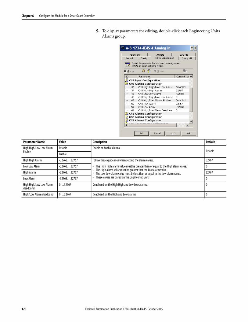
Chapter 6 Configure the Module for a SmartGuard Controller
5. To display parameters for editing, double-click each Engineering Units Alarms group.
Parameter Name Value Description Default
High High/Low Low Alarm Enable
Disable Enable or disable alarms.Disable
Enable
High High Alarm -32768…32767 Follow these guidelines when setting the alarm values.
• The High High alarm value must be greater than or equal to the High alarm value.• The High alarm value must be greater that the Low alarm value.• The Low Low alarm value must be less than or equal to the Low alarm value.• These values are based on the Engineering units
32767
Low Low Alarm -32768…32767 0
High Alarm -32768…32767 32767
Low Alarm -32768…32767 0
High High/Low Low Alarm deadband
0…32767 Deadband on the High High and Low Low alarms. 0
High/Low Alarm deadband 0…32767 Deadband on the High and Low alarms. 0
120 Rockwell Automation Publication 1734-UM013K-EN-P - October 2015
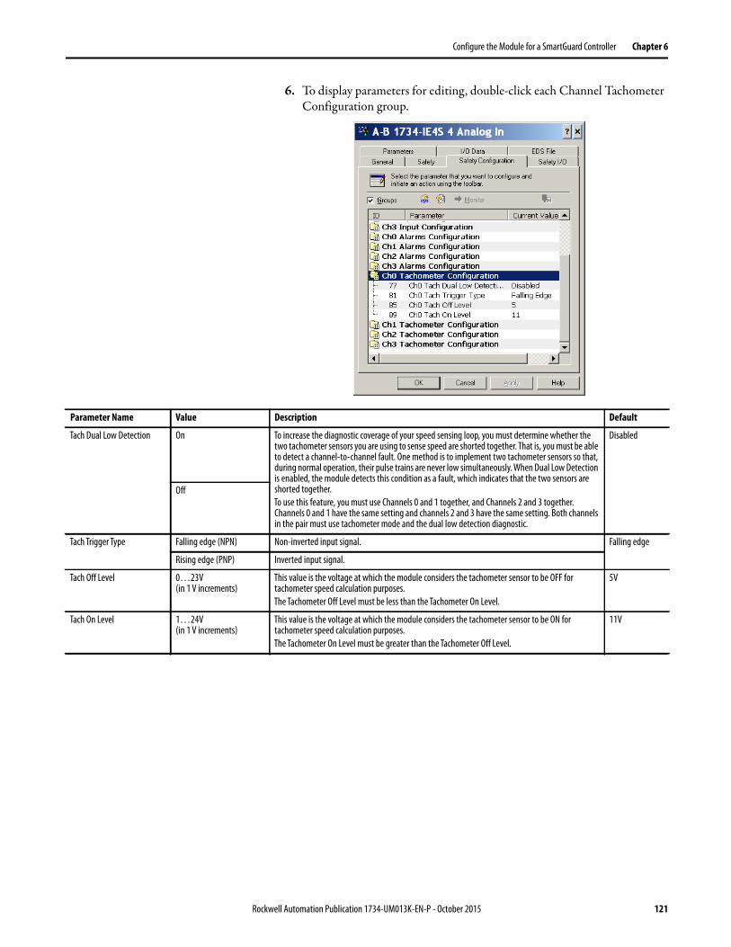
Configure the Module for a SmartGuard Controller Chapter 6
6. To display parameters for editing, double-click each Channel Tachometer Configuration group.
Parameter Name Value Description Default
Tach Dual Low Detection On To increase the diagnostic coverage of your speed sensing loop, you must determine whether the two tachometer sensors you are using to sense speed are shorted together. That is, you must be able to detect a channel-to-channel fault. One method is to implement two tachometer sensors so that, during normal operation, their pulse trains are never low simultaneously. When Dual Low Detection is enabled, the module detects this condition as a fault, which indicates that the two sensors are shorted together.
To use this feature, you must use Channels 0 and 1 together, and Channels 2 and 3 together. Channels 0 and 1 have the same setting and channels 2 and 3 have the same setting. Both channels in the pair must use tachometer mode and the dual low detection diagnostic.
Disabled
Off
Tach Trigger Type Falling edge (NPN) Non-inverted input signal. Falling edge
Rising edge (PNP) Inverted input signal.
Tach Off Level 0…23V (in 1 V increments)
This value is the voltage at which the module considers the tachometer sensor to be OFF for tachometer speed calculation purposes.
The Tachometer Off Level must be less than the Tachometer On Level.
5V
Tach On Level 1…24V (in 1 V increments)
This value is the voltage at which the module considers the tachometer sensor to be ON for tachometer speed calculation purposes.
The Tachometer On Level must be greater than the Tachometer Off Level.
11V
Rockwell Automation Publication 1734-UM013K-EN-P - October 2015 121

Chapter 6 Configure the Module for a SmartGuard Controller
Configure the SmartGuard Controller
To configure input and output connections to the controller and complete the setup of the controller, follow the procedures in the next sections.
Set Up the Input and Output Connections
1. In RSNetWorx for DeviceNet software, right-click the SmartGuard controller and choose Properties.
2. Click the Safety Connection tab to see a list of all Safety I/O modules currently in your project.
122 Rockwell Automation Publication 1734-UM013K-EN-P - October 2015

Configure the Module for a SmartGuard Controller Chapter 6
3. Right-click the POINT Guard I/O module and choose Add Connection.
The Add Safety Connection dialog box appears.
You can add individual safety connections for the inputs and outputs. The SmartGuard 600 controller can have up to 32 connections.
Rockwell Automation Publication 1734-UM013K-EN-P - October 2015 123

Chapter 6 Configure the Module for a SmartGuard Controller
4. To add a safety connection, from the Connection Name pull-down menu, choose one of these options.
The more status that is read, the larger the packet size.
5. From the Connection Type pull-down menu, for this example choose Multicast.
6. From the Configuration pull-down menu, for this example choose Configuration signature must match.
Choose Description
1734
-IB8
S
[IN] Safety Control of safety inputs
[IN] Safety + Combined Status(1) - Muting
• Control of safety inputs• Status for 1 bit for all inputs• Muting status is available
[IN] Safety + Pt. Status • Control of safety inputs• Individual status for each input point
[IN] Safety + Pt. Status - Muting
• Control of safety inputs• Individual status for each input point• Muting status available
[IN] Safety + Pt. Status- Muting - Test Output
• Control of safety inputs• Individual status for each input point• Muting status available• Test output status available
[OUT] Test Control of test outputs
1734
-OB8
S
[IN] Safety Monitor - Combined Status - Power
• Monitor safety outputs• Status for 1 bit for all outputs• Power status available
[IN] Safety Output Status • Individual status for each output point
[IN] Safety Output Status+ Monitor
• Individual status for each output point• Monitor safety outputs
[OUT] Safety Control of safety outputs
1734
-IE4
S(2)
[IN] Channel and Combined Alarm Status
Combined channel status and alarm status for each input point
[IN] Channel Status, Alarm Status
• Individual status for each input point• Combined alarm status for each input point• Power status
[OUT] Tach Reset Resets a latched overfrequency condition and enables the module to begin to calculate frequency again.
(1) Most digital input connections use Combined Status.
(2) Other connection options are available via RSNetWorx for DeviceNet software, but their use with a SmartGuard controller
is not recommended.
124 Rockwell Automation Publication 1734-UM013K-EN-P - October 2015

Configure the Module for a SmartGuard Controller Chapter 6
7. In the Requested Packet Interval (RPI) box, enter 10 ms.
8. In the Connection Reaction Time Limit (CRTL), enter 40.1 ms.
9. Click Add.
This value limits the packet size for normal communication. If detailed status is required when a fault occurs, the data can be read explicitly via MSG instructions.
10. Repeat steps 3…9 for each connection, being sure to assign input and output connections.
Notice that the connections for the 1734-IB8S module have 2 bytes. If you had selected individual point status, the input connection would be5 bytes.
11. Click Apply.
For further details, see the SmartGuard 600 Controllers User Manual, publication 1752-UM001, and SmartGuard 600 Controllers Safety Reference Manual, publication 1752-RM001.
Rockwell Automation Publication 1734-UM013K-EN-P - October 2015 125
http://www.literature.rockwellautomation.com/idc/groups/literature/documents/um/1752-um001_-en-p.pdf
http://www.literature.rockwellautomation.com/idc/groups/literature/documents/um/1752-um001_-en-p.pdf

Chapter 6 Configure the Module for a SmartGuard Controller
Complete the Set Up of the SmartGuard Controller
1. From the 1752-L24BBB dialog box, click Apply and then OK to accept the connection.
2. Place RSNetWorx from DeviceNet software back into Online mode. a. If you see this dialog box, click Yes to save changes.
b. Click OK to upload or download device information.
You see the following nodes after the browse.
126 Rockwell Automation Publication 1734-UM013K-EN-P - October 2015

Configure the Module for a SmartGuard Controller Chapter 6
Save and Download Module Configuration
We recommend that after a module is configured you save your work
If the MS and NS status indicators on the POINT Guard I/O module are not both solid green after download, ownership has the potential to have been lost. The ownership is based on the following:
• POINT Guard I/O module number• POINT Guard I/O safety network number • SmartGuard slot number• SmartGuard safety network number• Path from SmartGuard controller to POINT Guard I/O module• Configuration signature
If any of the preceding parameters change, the connection between the SmartGuard controller and the POINT Guard I/O module is lost, and a yellow yield icon appears in the RSNetWorx for DeviceNet tree. For more information, see Chapter 8.
IMPORTANT If you have not followed the configuration guidelines in the parameter tables
found in Configure Safety Analog Inputs on page 117, the error message
“Invalid Configuration Parameter occurred while attempting to configure the
safety device” appears in the Error Log during download.
Rockwell Automation Publication 1734-UM013K-EN-P - October 2015 127

Chapter 6 Configure the Module for a SmartGuard Controller
Notes:
128 Rockwell Automation Publication 1734-UM013K-EN-P - October 2015

Chapter 7
Configuring Safety Connections between a GuardLogix Controller and POINT Guard I/O Modules on a DeviceNet Network
To use POINT Guard I/O™ modules with a GuardLogix® controller via a DeviceNet network, you must use a 1734-PDN module in place of an adapter. When using a 1734-PDN module, you must use RSNetWorx™ for DeviceNet software to configure the POINT Guard I/O modules. The Generic DeviceNet Safety Module profile in the Logix Designer application to use the module data inside of the safety task.
Configure the Module in RSNetWorx for DeviceNet Software
Before you can add the module to the GuardLogix controller project, you must perform a number of tasks in RSNetWorx for DeviceNet software.
1. Set the node address of the module by using the Node Commissioning Tool. See Set the Node Address on page 108.
2. Configure the inputs and outputs of the module. See the following sections:• Configure Digital Safety Inputs and Test Outputs on page 113• Configure Digital Safety Outputs on page 116• Configure Safety Analog Inputs on page 117
Topic Page
Configure the Module in RSNetWorx for DeviceNet Software 129
Add the POINT Guard I/O Module to the Controller Project 130
Complete the Safety Configuration 134
Download the DeviceNet Network Configuration 136
Verify Your DeviceNet Safety Configuration 137
Rockwell Automation Publication 1734-UM013K-EN-P - October 2015 129

Chapter 7 Configuring Safety Connections between a GuardLogix Controller and POINT Guard I/O Modules on a DeviceNet Network
Add the POINT Guard I/O Module to the Controller Project
Follow these steps to connect to the controller.
1. In the Logix Designer application, right-click the DeviceNet network and choose New Module.
2. In the Select Module Type dialog box, check Safety and Allen-Bradley®.
3. Select the Generic DeviceNet Safety Module and click Create.
4. On the New Module dialog box, click Change.
130 Rockwell Automation Publication 1734-UM013K-EN-P - October 2015

Configuring Safety Connections between a GuardLogix Controller and POINT Guard I/O Modules on a DeviceNet Network Chapter 7
5. On the Module Definition dialog box, set these parameters for your module.
6. Click the Connection tab.
7. Set the Configuration Assembly Instance to 864 for all POINT Guard modules.
Cat. No. Product Type Product Code
1734-IB8S 35 15
1734-OB8S 35 16
1734-IE4S 42 1
1734-IB8S Module 1734-IE4S Module
Rockwell Automation Publication 1734-UM013K-EN-P - October 2015 131
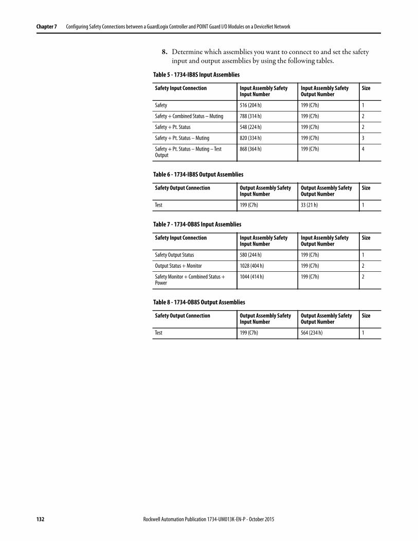
Chapter 7 Configuring Safety Connections between a GuardLogix Controller and POINT Guard I/O Modules on a DeviceNet Network
8. Determine which assemblies you want to connect to and set the safety input and output assemblies by using the following tables.
Table 5 - 1734-IB8S Input Assemblies
Safety Input Connection Input Assembly Safety Input Number
Input Assembly Safety Output Number
Size
Safety 516 (204 h) 199 (C7h) 1
Safety + Combined Status – Muting 788 (314 h) 199 (C7h) 2
Safety + Pt. Status 548 (224 h) 199 (C7h) 2
Safety + Pt. Status – Muting 820 (334 h) 199 (C7h) 3
Safety + Pt. Status – Muting – Test Output
868 (364 h) 199 (C7h) 4
Table 6 - 1734-IB8S Output Assemblies
Safety Output Connection Output Assembly Safety Input Number
Output Assembly Safety Output Number
Size
Test 199 (C7h) 33 (21 h) 1
Table 7 - 1734-OB8S Input Assemblies
Safety Input Connection Input Assembly Safety Input Number
Input Assembly Safety Output Number
Size
Safety Output Status 580 (244 h) 199 (C7h) 1
Output Status + Monitor 1028 (404 h) 199 (C7h) 2
Safety Monitor + Combined Status + Power
1044 (414 h) 199 (C7h) 2
Table 8 - 1734-OB8S Output Assemblies
Safety Output Connection Output Assembly Safety Input Number
Output Assembly Safety Output Number
Size
Test 199 (C7h) 564 (234 h) 1
132 Rockwell Automation Publication 1734-UM013K-EN-P - October 2015

Configuring Safety Connections between a GuardLogix Controller and POINT Guard I/O Modules on a DeviceNet Network Chapter 7
Individual members of each assembly are listed in Appendix F.
9. Click OK.
10. On the Safety Tab, uncheck the Configuration Signature checkbox.
11. Click OK and OK again to add the module to the I/O Configuration tree.
Table 9 - 1734-IE4S Input Assemblies
Safety Input Connection Input Assembly Safety Input Number
Input Assembly Safety Output Number
Size
Safety + Status 402 (192 h) 199 (C7h) 9
Safety + Status + Alarms 786 (312 h) 199 (C7h) 13
Safety + Status + Process Status + Fault Reason + Alarms
802 (322 h) 199 (C7h) 18
Table 10 - 1734-IE4S Output Assemblies
Safety Output Connection Output Assembly Safety Input Number
Output Assembly Safety Output Number
Size
Safety Tachometer 199 (C7h) 770 (302 h) 1
IMPORTANT If you are using the 1734-IE4S module with a GuardLogix system, use the
application program to evaluate any dual channel requirements and determine
any process alarms.
Rockwell Automation Publication 1734-UM013K-EN-P - October 2015 133
Chapter 7 Configuring Safety Connections between a GuardLogix Controller and POINT Guard I/O Modules on a DeviceNet Network
Complete the Safety Configuration
Follow these steps to copy the configuration signature and safety network number from RSNetWorx for DeviceNet software to the generic profile you configure in the Logix Designer application.
1. In RSNetWorx for DeviceNet software, double-click the module.
2. On the Safety tab, click Copy Signature.
3. In the Logix Designer application, right-click the DEVICENET-SAFETYMODULE and choose Properties.
134 Rockwell Automation Publication 1734-UM013K-EN-P - October 2015
Configuring Safety Connections between a GuardLogix Controller and POINT Guard I/O Modules on a DeviceNet Network Chapter 7
4. On the Safety tab, check the Configuration Signature checkbox.
5. Click Paste.
6. In RSNetWorx for DeviceNet software, click Copy to copy the safety network number.
Rockwell Automation Publication 1734-UM013K-EN-P - October 2015 135
Chapter 7 Configuring Safety Connections between a GuardLogix Controller and POINT Guard I/O Modules on a DeviceNet Network
7. On the General tab in the Logix Designer application, click next to the safety network number field.
8. Click Paste.
Download the DeviceNet Network Configuration
Before you download, you must go online to the DeviceNet network by using RSNetWorx for DeviceNet software. Your computer and the devices you wish to communicate with must be connected to the DeviceNet network.
When you go online to a DeviceNet network, RSNetWorx for DeviceNet software browses the network one time and shows you the devices on the network. If you go online, this action does not upload (read) or download (change) the parameters of any of the devices.
To download the DeviceNet network configuration, follow these steps.
1. Go online by clicking the online icon.
2. Browse to the DeviceNet network and click OK at the prompt.
3. Download your configuration to the network by right-clicking the device and then choose Download to Device.
4. To download, click yes.
136 Rockwell Automation Publication 1734-UM013K-EN-P - October 2015
Configuring Safety Connections between a GuardLogix Controller and POINT Guard I/O Modules on a DeviceNet Network Chapter 7
Verify Your DeviceNet Safety Configuration
The Safety Device Verification Wizard, which is accessed from RSNetWorx for DeviceNet software, guides you through the verification of the configuration of your safety devices and provides the means for safety-locking those devices. The verification process includes upload and comparison of the configuration that is stored in the device and the configuration that is stored in the RSNetWorx for DeviceNet software configuration file. The configuration is displayed in a report to facilitate visual verification and record keeping.
To run the Safety Device Verification Wizard, follow these steps.
1. Choose Network >Safety Device Verification Wizard.
2. On the Welcome dialog box, click Next.
IMPORTANT Before running the Safety Device Verification Wizard, you must browse and
upload your network and test the safety devices and all of their safety
functions on your network to verify that they are operating properly. You must
fully test your application before safety-locking your devices.
IMPORTANT Some devices on your network can not support verification by the Safety
Device Verification Wizard. To determine the method that is required for
verifying these devices, consult the user documentation.
Rockwell Automation Publication 1734-UM013K-EN-P - October 2015 137
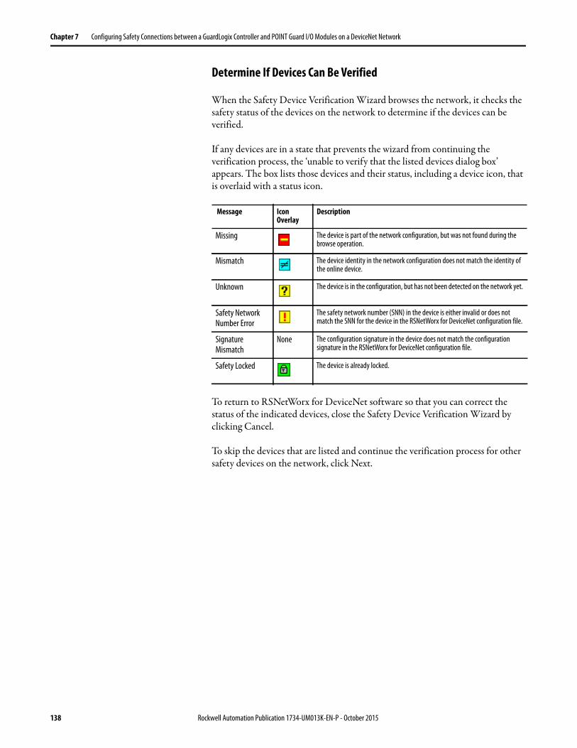
Chapter 7 Configuring Safety Connections between a GuardLogix Controller and POINT Guard I/O Modules on a DeviceNet Network
Determine If Devices Can Be Verified
When the Safety Device Verification Wizard browses the network, it checks the safety status of the devices on the network to determine if the devices can be verified.
If any devices are in a state that prevents the wizard from continuing the verification process, the ‘unable to verify that the listed devices dialog box’ appears. The box lists those devices and their status, including a device icon, that is overlaid with a status icon.
To return to RSNetWorx for DeviceNet software so that you can correct the status of the indicated devices, close the Safety Device Verification Wizard by clicking Cancel.
To skip the devices that are listed and continue the verification process for other safety devices on the network, click Next.
Message Icon Overlay
Description
Missing The device is part of the network configuration, but was not found during the browse operation.
Mismatch The device identity in the network configuration does not match the identity of the online device.
Unknown The device is in the configuration, but has not been detected on the network yet.
Safety Network Number Error
The safety network number (SNN) in the device is either invalid or does not match the SNN for the device in the RSNetWorx for DeviceNet configuration file.
Signature Mismatch
None The configuration signature in the device does not match the configuration signature in the RSNetWorx for DeviceNet configuration file.
Safety Locked The device is already locked.
138 Rockwell Automation Publication 1734-UM013K-EN-P - October 2015
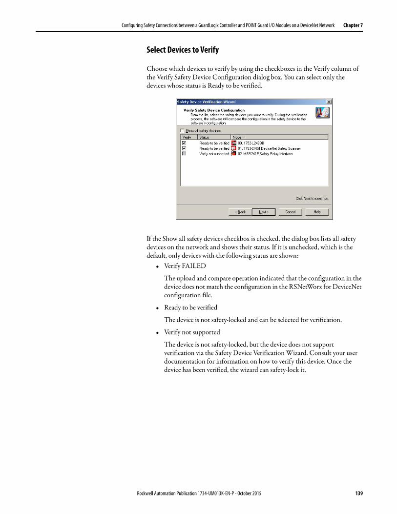
Configuring Safety Connections between a GuardLogix Controller and POINT Guard I/O Modules on a DeviceNet Network Chapter 7
Select Devices to Verify
Choose which devices to verify by using the checkboxes in the Verify column of the Verify Safety Device Configuration dialog box. You can select only the devices whose status is Ready to be verified.
If the Show all safety devices checkbox is checked, the dialog box lists all safety devices on the network and shows their status. If it is unchecked, which is the default, only devices with the following status are shown:
• Verify FAILED
The upload and compare operation indicated that the configuration in the device does not match the configuration in the RSNetWorx for DeviceNet configuration file.
• Ready to be verified
The device is not safety-locked and can be selected for verification.
• Verify not supported
The device is not safety-locked, but the device does not support verification via the Safety Device Verification Wizard. Consult your user documentation for information on how to verify this device. Once the device has been verified, the wizard can safety-lock it.
Rockwell Automation Publication 1734-UM013K-EN-P - October 2015 139
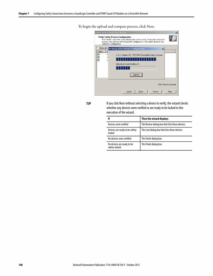
Chapter 7 Configuring Safety Connections between a GuardLogix Controller and POINT Guard I/O Modules on a DeviceNet Network
To begin the upload and compare process, click Next.
TIP If you click Next without selecting a device to verify, the wizard checks
whether any devices were verified or are ready to be locked in this
execution of the wizard.
If Then the wizard displays
Devices were verified The Review dialog box that lists those devices.
Devices are ready to be safety-locked
The Lock dialog box that lists those devices.
No devices were verified The Finish dialog box.
No devices are ready to be safety-locked
The Finish dialog box.
140 Rockwell Automation Publication 1734-UM013K-EN-P - October 2015

Configuring Safety Connections between a GuardLogix Controller and POINT Guard I/O Modules on a DeviceNet Network Chapter 7
Review the Safety Device Verification Reports
The Review page displays safety devices with status of either Verify FAILED or Ready to be Safety Locked.
1. Click Review in the Report column to launch the HTML report of the device in your default browser.
2. To generate an HTML verification report for all devices listed, click Review All.
3. Review and print the verification reports for your records.
Lock Safety Devices
TIP If the status of a device is Verify FAILED, more information is provided
in the verification failure report.
IMPORTANT You must review the device configurations and record the configuration
signatures before operating a safety application.
IMPORTANT Before you lock your safety device configurations, you must perform all
verification steps that are required for your application.
Rockwell Automation Publication 1734-UM013K-EN-P - October 2015 141

Chapter 7 Configuring Safety Connections between a GuardLogix Controller and POINT Guard I/O Modules on a DeviceNet Network
1. Choose which devices to safety-lock by checking the checkbox in the Lock column for each device that is ready to be safety-locked.
2. You must check the acknowledgement checkbox before the locking process can continue.
3. Click Next.
The wizard performs a final comparison of the configuration signature in each safety device to its configuration signature in RSNetWorx for DeviceNet software before locking the device.
4. View the Safety Device Verification Wizard Summary
Before closing, the wizard displays a summary of all safety devices that were safety-locked. It also displays the number of safety devices that still must be safety-locked, and lets you display the verified and safety-locked state of all safety devices on the network.
5. To close the wizard, click Finish.
142 Rockwell Automation Publication 1734-UM013K-EN-P - October 2015

Chapter 8
Replacing POINT Guard I/O Modules
This chapter provides information on replacing POINT Guard I/O™ modules when they are connected to GuardLogix® or SmartGuard™ controllers. For more information on these controllers, refer to the controller publications listed in the Additional Resources on page 13.
A major difference in functionality between the GuardLogix and SmartGuard safety controllers affects the replacement of safety I/O modules. GuardLogix controllers retain I/O module configuration onboard and are able to download the configuration to the replacement module. SmartGuard controllers do not retain I/O module configuration, so you must use RSNetWorx™ for DeviceNet software to download the configuration to the replacement module.
The Safety Network Number Replacing a safety I/O module that sits on a CIP safety network is more complicated than replacing standard devices because of the safety network number (SNN). The module number and SNN make up the DeviceID of the safety module. Safety devices require this more complex identifier to make sure that duplicate module numbers do not compromise communication between the correct safety devices.
Topic Page
The Safety Network Number 143
Manually Setting the Safety Network Number 144
Resetting a Module to Out-of-box Condition 145
Replacing a Module in a GuardLogix System on an EtherNet/IP Network 148
Replacing a Module When Using a SmartGuard or GuardLogix Controller on a DeviceNet Network
155
Rockwell Automation Publication 1734-UM013K-EN-P - October 2015 143
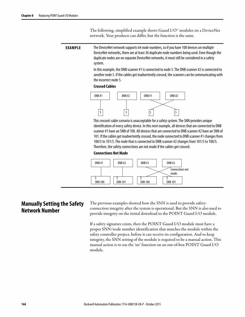
Chapter 8 Replacing POINT Guard I/O Modules
The following, simplified example shows Guard I/O™ modules on a DeviceNet network. Your products can differ, but the function is the same.
Manually Setting the Safety Network Number
The previous examples showed how the SNN is used to provide safety-connection integrity after the system is operational. But the SNN is also used to provide integrity on the initial download to the POINT Guard I/O module.
If a safety signature exists, then the POINT Guard I/O module must have a proper SNN/node number identification that matches the module within the safety controller project, before it can receive its configuration. And to keep integrity, the SNN setting of the module is required to be a manual action. This manual action is to use the ‘set’ function on an out-of-box POINT Guard I/O module.
EXAMPLE The DeviceNet network supports 64 node numbers, so if you have 100 devices on multiple
DeviceNet networks, there are at least 36 duplicate node numbers being used. Even though the
duplicate nodes are on separate DeviceNet networks, it must still be considered in a safety
system.
In this example, the DNB scanner #1 is connected to node 5. The DNB scanner #2 is connected to
another node 5. If the cables get inadvertently crossed, the scanners can be communicating with
the incorrect node 5.
Crossed Cables
This crossed-cable scenario is unacceptable for a safety system. The SNN provides unique
identification of every safety device. In this next example, all devices that are connected to DNB
scanner #1 have an SNN of 100. All devices that are connected to DNB scanner #2 have an SNN of
101. If the cables get inadvertently crossed, the node connected to DNB scanner #1 changes from
100/5 to 101/5. The node that is connected to DNB scanner #2 changes from 101/5 to 100/5.
Therefore, the safety connections are not made if the cables get crossed.
Connections Not Made
DNB #1 DNB #2 DNB #1 DNB #2
5 5 5 5
DNB #1 DNB #2 DNB #1 DNB #2
5SNN 100
5SNN 101
5SNN 100
5SNN 101
Connections not made.
144 Rockwell Automation Publication 1734-UM013K-EN-P - October 2015
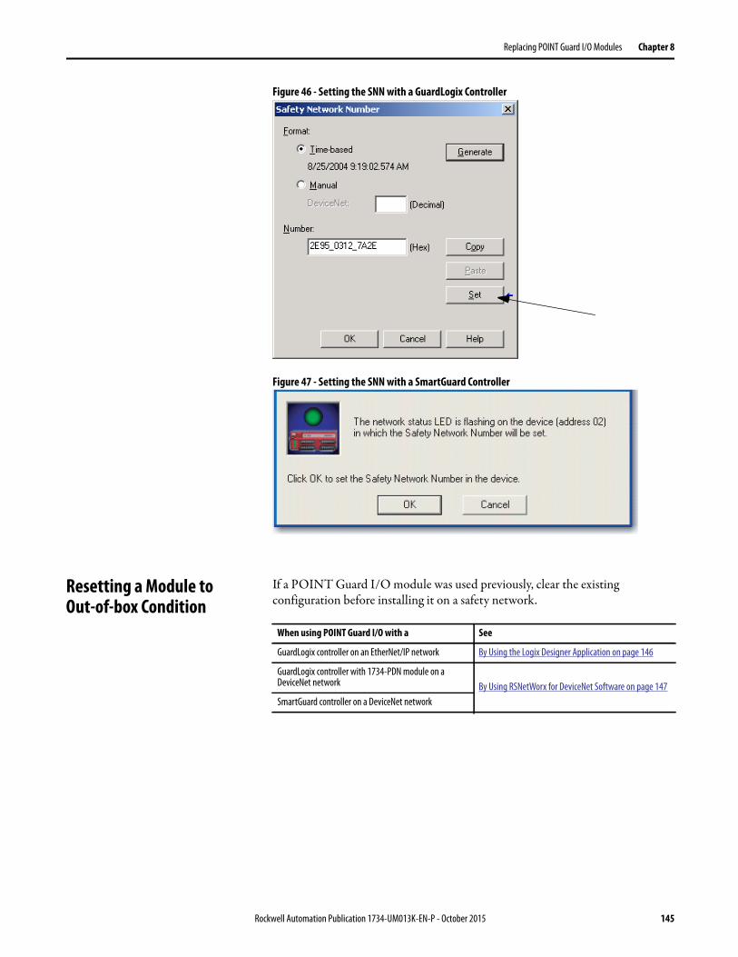
Replacing POINT Guard I/O Modules Chapter 8
Figure 46 - Setting the SNN with a GuardLogix Controller
Figure 47 - Setting the SNN with a SmartGuard Controller
Resetting a Module to Out-of-box Condition
If a POINT Guard I/O module was used previously, clear the existing configuration before installing it on a safety network.
When using POINT Guard I/O with a See
GuardLogix controller on an EtherNet/IP network By Using the Logix Designer Application on page 146
GuardLogix controller with 1734-PDN module on a DeviceNet network By Using RSNetWorx for DeviceNet Software on page 147
SmartGuard controller on a DeviceNet network
Rockwell Automation Publication 1734-UM013K-EN-P - October 2015 145

Chapter 8 Replacing POINT Guard I/O Modules
By Using the Logix Designer Application
When the Logix Designer application is online, the Safety tab of the Module Properties dialog box displays the current configuration ownership. When the opened project owns the configuration, Local is displayed. When a second device owns the configuration, Remote is displayed, along with the safety network number (SNN), and node address or slot number of the configuration owner. Communication error is displayed if the module read fails.
If the connection is Local, you must inhibit the module connection before you reset ownership. To inhibit the module:
1. Right-click the module and choose Properties.
2. Click the Connection tab.
3. Check the inhibit module checkbox.
4. Click Apply and then OK.
Follow these steps to reset the module to its out-of-box configuration when online.
1. Right-click the module and choose Properties.
2. Click the Safety tab.
3. Click Reset Ownership.
146 Rockwell Automation Publication 1734-UM013K-EN-P - October 2015
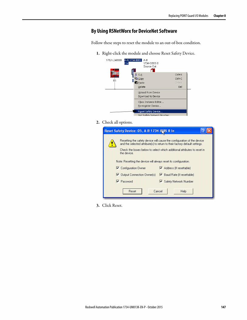
Replacing POINT Guard I/O Modules Chapter 8
By Using RSNetWorx for DeviceNet Software
Follow these steps to reset the module to an out-of-box condition.
1. Right-click the module and choose Reset Safety Device.
2. Check all options.
3. Click Reset.
Rockwell Automation Publication 1734-UM013K-EN-P - October 2015 147

Chapter 8 Replacing POINT Guard I/O Modules
Replacing a Module in a GuardLogix System on an EtherNet/IP Network
If you are relying on a portion of the CIP Safety system to maintain SIL 3 behavior during module replacement and functional testing, you must not use the Configure Always feature. Go to Replacement with ‘Configure Only When No Safety Signature Exists’ Enabled on page 148.
If you are not relying on the entire routable CIP Safety control system to maintain SIL 3/PLe during the replacement and functional testing of a module, you can use the Configure Always feature. Go to Replacement with ‘Configure Always’ Enabled on page 153.
Module replacement is configured on the Safety tab of the GuardLogix controller.
Replacement with ‘Configure Only When No Safety Signature Exists’ Enabled
When a module is replaced, the configuration is downloaded from the safety controller if the DeviceID of the new module matches the original. The DeviceID is a combination of the node/IP address and the safety network number (SNN) and is updated whenever the SNN is set.
148 Rockwell Automation Publication 1734-UM013K-EN-P - October 2015
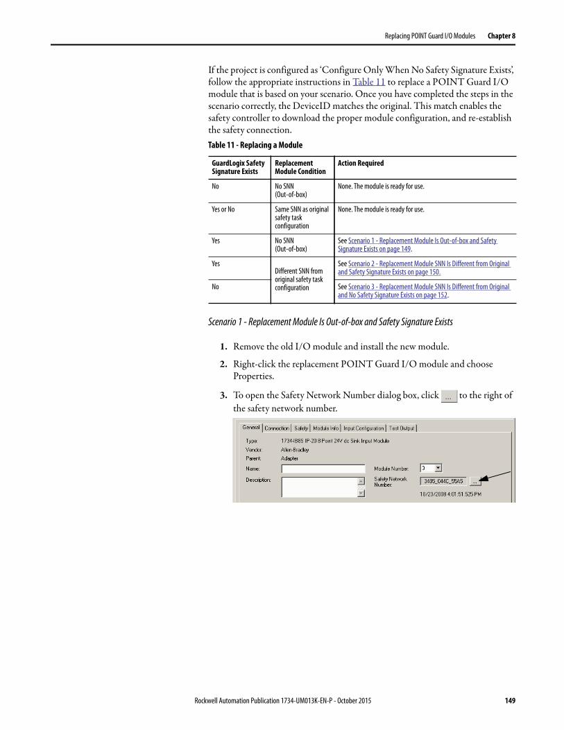
Replacing POINT Guard I/O Modules Chapter 8
If the project is configured as ‘Configure Only When No Safety Signature Exists’, follow the appropriate instructions in Table 11 to replace a POINT Guard I/O module that is based on your scenario. Once you have completed the steps in the scenario correctly, the DeviceID matches the original. This match enables the safety controller to download the proper module configuration, and re-establish the safety connection.
Scenario 1 - Replacement Module Is Out-of-box and Safety Signature Exists
1. Remove the old I/O module and install the new module.
2. Right-click the replacement POINT Guard I/O module and choose Properties.
3. To open the Safety Network Number dialog box, click to the right of the safety network number.
Table 11 - Replacing a Module
GuardLogix Safety Signature Exists
Replacement Module Condition
Action Required
No No SNN(Out-of-box)
None. The module is ready for use.
Yes or No Same SNN as original safety task configuration
None. The module is ready for use.
Yes No SNN (Out-of-box)
See Scenario 1 - Replacement Module Is Out-of-box and Safety Signature Exists on page 149.
YesDifferent SNN from original safety task configuration
See Scenario 2 - Replacement Module SNN Is Different from Original and Safety Signature Exists on page 150.
No See Scenario 3 - Replacement Module SNN Is Different from Original and No Safety Signature Exists on page 152.
Rockwell Automation Publication 1734-UM013K-EN-P - October 2015 149
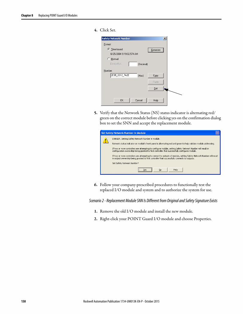
Chapter 8 Replacing POINT Guard I/O Modules
4. Click Set.
5. Verify that the Network Status (NS) status indicator is alternating red/green on the correct module before clicking yes on the confirmation dialog box to set the SNN and accept the replacement module.
6. Follow your company-prescribed procedures to functionally test the replaced I/O module and system and to authorize the system for use.
Scenario 2 - Replacement Module SNN Is Different from Original and Safety Signature Exists
1. Remove the old I/O module and install the new module.
2. Right-click your POINT Guard I/O module and choose Properties.
150 Rockwell Automation Publication 1734-UM013K-EN-P - October 2015
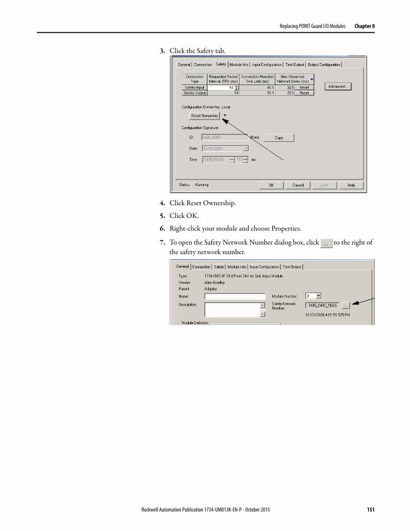
Replacing POINT Guard I/O Modules Chapter 8
3. Click the Safety tab.
4. Click Reset Ownership.
5. Click OK.
6. Right-click your module and choose Properties.
7. To open the Safety Network Number dialog box, click to the right of the safety network number.
Rockwell Automation Publication 1734-UM013K-EN-P - October 2015 151

Chapter 8 Replacing POINT Guard I/O Modules
8. Click Set.
9. Verify that the Network Status (NS) status indicator is alternating red/green on the correct module before clicking yes on the confirmation dialog box to set the SNN and accept the replacement module.
10. Follow your company-prescribed procedures to test the replaced I/O module and system and to authorize the system for use.
Scenario 3 - Replacement Module SNN Is Different from Original and No Safety Signature Exists
1. Remove the old I/O module and install the new module.
2. Right-click your POINT Guard I/O module and choose Properties.
152 Rockwell Automation Publication 1734-UM013K-EN-P - October 2015

Replacing POINT Guard I/O Modules Chapter 8
3. Click the Safety tab.
4. Click Reset Ownership.
5. Click OK.
6. Follow your company-prescribed procedures to test the replaced I/O module and system and to authorize the system for use.
Replacement with ‘Configure Always’ Enabled
When the ‘Configure Always’ feature is enabled, the controller automatically checks for and connects to a replacement module that meets all the following requirements:
• The controller has configuration data for a compatible module at that network address.
• The module is in out-of-box condition or has an SNN that matches the configuration.
If the project is configured for ‘Configure Always’, follow the appropriate steps to replace a POINT Guard I/O module.
ATTENTION: Enable the ‘Configure Always’ feature only if the entire CIP Safety
Control System is not being relied on to maintain SIL 3 behavior during the
replacement and functional testing of a module.
Do not place modules that are in the out-of-box condition on a CIP Safety network
when the Configure Always feature is enabled, except while following this
replacement procedure.
Rockwell Automation Publication 1734-UM013K-EN-P - October 2015 153

Chapter 8 Replacing POINT Guard I/O Modules
1. Remove the old I/O module and install the new module.
2. Right-click your POINT Guard I/O module and choose Properties.
3. Click the Safety tab.
4. Click Reset Ownership.
5. Click OK.
6. Follow your company-prescribed procedures to functionally test the replaced I/O module and system and to authorize the system for use.
If Then
the module is in out-of-box condition go to step 6.
No action is needed for the GuardLogix controller to take ownership of the module.
an SNN mismatch error occurs go to the next step to reset the module to out-of-box condition.
154 Rockwell Automation Publication 1734-UM013K-EN-P - October 2015

Replacing POINT Guard I/O Modules Chapter 8
Replacing a Module When Using a SmartGuard or GuardLogix Controller on a DeviceNet Network
To replace an I/O module when the module and the controller are on a DeviceNet network, follow these steps.
1. Replace the module and match the node number of the original module.
2. In RSNetWorx for DeviceNet software, open your project.
If the replacement module is out-of-box or has an SNN that does not match the original module, the module appears with an exclamation mark.
3. Right-click the module and choose Download to Device.
4. Click Yes to confirm.
5. To set the SNN on the replacement module, click Download on the Safety Network Number Mismatch dialog box.
Rockwell Automation Publication 1734-UM013K-EN-P - October 2015 155

Chapter 8 Replacing POINT Guard I/O Modules
6. Verify that the (NS) Network status indicator is flashing on the correct module and click OK to set the SNN on that device.
RSNetWorx for DeviceNet software confirms that the SNN has been set.
Once the download successfully completes, the main project view displays this message: ‘The device at address xx has been downloaded. Any device-specific messages that are related to the download operation are displayed separately.’
156 Rockwell Automation Publication 1734-UM013K-EN-P - October 2015

Replacing POINT Guard I/O Modules Chapter 8
If the configuration is correct based on the original DNT file, the SNN and configuration signature now match that of the original. If you are already connected to the controller, a connection is made. The controller does not need to be taken out of Run mode to download to the replacement module.
If you download this configuration to a temporary setup, place the module on the network and it automatically connects to the controller.
If the configuration downloaded to the module was not from the original DNT file, the configuration signature does not match the original. Even if you recreate the same parameters in a new DNT file, the time and date portions of the signature are different so the connection to the controller is not made. If this situation occurs, click the Safety Connection tab for the controller that prompted you that the configuration signature is different and provides you with the option to match the new configuration signature. However, you must first revalidate the safety system because it is not using the original DNT file.
7. Click Yes.
This selection takes the controller out of Run mode and prompts you to download the changes.
8. Click Yes to download the new connection configuration to the SmartGuard controller.
After the download is complete, place the controller back in Run mode and the connection to the replacement module is established.
9. Follow your company-prescribed procedures to functionally test the replaced I/O module and system and to authorize the system for use.
Rockwell Automation Publication 1734-UM013K-EN-P - October 2015 157

Chapter 8 Replacing POINT Guard I/O Modules
Notes:
158 Rockwell Automation Publication 1734-UM013K-EN-P - October 2015
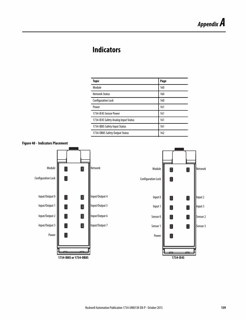
Appendix A
Indicators
Figure 48 - Indicators Placement
Topic Page
Module 160
Network Status 160
Configuration Lock 160
Power 161
1734-IE4S Sensor Power 161
1734-IE4S Safety Analog Input Status 161
1734-IB8S Safety Input Status 161
1734-OB8S Safety Output Status 162
Module Network
Power
Input/Output 0
Input/Output 1
Input/Output 2
Input/Output 3
Input/Output 5
Input/Output 6
Input/Output 7
Input/Output 4
Configuration Lock
1734-IB8S or 1734-OB8S
Module Network
Power
Input 0
Input 1
Sensor 0
Sensor 1
Input 3
Sensor 2
Sensor 3
Input 2
Configuration Lock
1734-IE4S
Rockwell Automation Publication 1734-UM013K-EN-P - October 2015 159
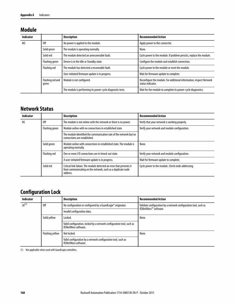
Appendix A Indicators
Module
Network Status
Configuration Lock
Indicator Description Recommended Action
MS Off No power is applied to the module. Apply power to this connector.
Solid green The module is operating normally. None.
Solid red The module detected an unrecoverable fault. Cycle power to the module. If problem persists, replace the module.
Flashing green Device is in the Idle or Standby state. Configure the module and establish connection.
Flashing red The module has detected a recoverable fault. Cycle power to the module or reset the module.
User-initiated firmware update is in progress. Wait for firmware update to complete.
Flashing red and green
Module is not configured. Reconfigure the module. For additional information, inspect Network status indicator.
The module is performing its power-cycle diagnostic tests. Wait for the module to complete its power-cycle diagnostics.
Indicator Description Recommended Action
NS Off The module is not online with the network or there is no power. Verify that your network is working properly.
Flashing green Module online with no connections in established state. Verify your network and module configuration.
The module identified the communication rate of the network but no connections are established.
Solid green Module online with connections in established state. The module is operating normally.
None.
Flashing red One or more I/O connections are in timed-out state. Verify your network and module configuration.
A user-initiated firmware update is in progress. Wait for firmware update to complete.
Solid red Critical link failure. The module detected an error that prevents it from communicating on the network, such as a duplicate node address.
Cycle power to the module. Check node addressing.
Indicator Description Recommended Action
LK(1) Off No configuration or configured by a GuardLogix® originator. Validate configuration by a network configuration tool, such as RSNetWorx™ software.
Invalid configuration data.
Solid yellow Locked. None.
Valid configuration, locked by a network configuration tool, such as RSNetWorx software.
Flashing yellow Not locked. None.
Valid configuration by a network configuration tool, such as RSNetWorx software.
(1) Not applicable when used with GuardLogix controllers.
160 Rockwell Automation Publication 1734-UM013K-EN-P - October 2015

Indicators Appendix A
Power
1734-IE4S Sensor Power
1734-IE4S Safety Analog Input Status
1734-IB8S Safety Input Status
Indicator Description Recommended Action
PWR Off No field power applied. Apply field power.
Green Normal condition, field power supplied and within specification. None.
Yellow Field power out of specification. The module is configured to use sensor power, and either the sensor is drawing too much current (short in the wiring or sensor), or the sensor is not drawing any current (broken wire or sensor).
Check your connectors, wiring, and voltages.
Indicator Description Recommended Action
S0…S3 Off Sensor power is not used. None.
Green Sensor power is used. None.
Red Over-current or under-current sensor power fault. Check connectors, wiring, and power supply.
Indicator Description Recommended Action
0…3(1) Off Safety analog input is not used or the module is being configured. Reconfigure the channel, if desired.
Yellow Safety analog input is configured for use and no faults exist. None.
Red A fault has been detected in the analog input signal path. Check the fault code in the module that uses one of the data assemblies that contains the Fault Reason. See Appendix B for details.
Check configuration, field wiring, and devices. If no problem found, replace module.
Flashing red A fault has been detected in the partner input signal path of a dual-input configuration.
Check the field wiring and verify your configuration for the partner circuit. If no problem found, replace module.
(1) Indicator behavior in Tachometer mode facilitates machine setup and troubleshooting. When the tachometer signal is below the configured OFF threshold, the indicator is off. When the tachometer signal
is above the ON threshold, the indicator is yellow. Status indicator behavior during normal operation is dependent upon the module update rate and is not intended to indicate the actual tachometer
input. When the input rate is above 30 Hz, the status indicator is solid yellow. When the input rate is below 30 Hz, the status indicator is flashing yellow as the signal turns on and off.
Indicator Description Recommended Action
0…7 Off Safety input is off, or module is being configured. Turn on the safety input or reconfigure the channel, if desired.
Yellow Safety input is on. None.
Red A fault in the external wiring or input circuit has been detected. Check configuration, field wiring, and devices. If no problem found, replace module.
Flashing red A fault in the partner input circuit of a dual-input configuration has been detected.
Check the field wiring and verify your configuration for the partner circuit. If no problem found, replace module.
Rockwell Automation Publication 1734-UM013K-EN-P - October 2015 161

Appendix A Indicators
1734-OB8S Safety Output StatusIndicator Description Recommended Action
0…7 Off Safety output is off, or module is being configured. Turn on the safety output or reconfigure the channel, if desired.
Yellow Safety output is on. None.
Red A fault in the output circuit has been detected. Check the circuit wiring and end device. If no problem found, replace module.
The tag values in a dual output configuration do not have the same value.
Make sure that logic is driving tag values to the same state (off or on).
Flashing red A fault in the partner output circuit of a dual-output configuration has been detected.
Check the circuit wiring and end device of the partner. If no problem found, replace module.
162 Rockwell Automation Publication 1734-UM013K-EN-P - October 2015
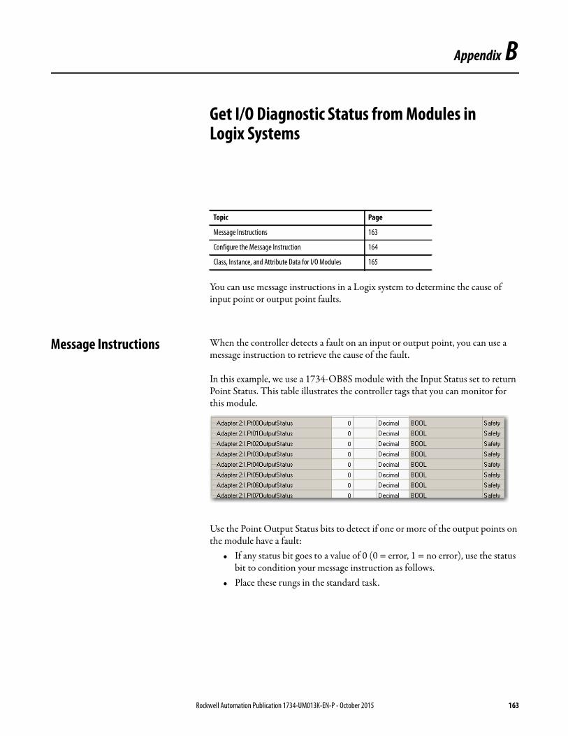
Appendix B
Get I/O Diagnostic Status from Modules in Logix Systems
You can use message instructions in a Logix system to determine the cause of input point or output point faults.
Message Instructions When the controller detects a fault on an input or output point, you can use a message instruction to retrieve the cause of the fault.
In this example, we use a 1734-OB8S module with the Input Status set to return Point Status. This table illustrates the controller tags that you can monitor for this module.
Use the Point Output Status bits to detect if one or more of the output points on the module have a fault:
• If any status bit goes to a value of 0 (0 = error, 1 = no error), use the status bit to condition your message instruction as follows.
• Place these rungs in the standard task.
Topic Page
Message Instructions 163
Configure the Message Instruction 164
Class, Instance, and Attribute Data for I/O Modules 165
Rockwell Automation Publication 1734-UM013K-EN-P - October 2015 163

Appendix B Get I/O Diagnostic Status from Modules in Logix Systems
This sample ladder logic is monitoring the status of output point 3. This ladder logic rung examines the Output Point Status and, when a fault is detected (0 = error), the message instruction is executed.
Configure the Message Instruction
Follow this procedure to edit the Message Configuration dialog box.
1. In the Message Instruction in the ladder logic, click the icon.
2. On the Configuration tab, enter the appropriate data for what you want to monitor.a. From the Service Type pull-down menu, choose Get Attribute Single.b. Enter the Class, Instance, and Attribute data, that refers to the
appropriate tables on pages 165…166.
3. On the Communication tab, specify the path for the message.
This example illustrates values that you enter to determine the reason for the fault on Output 3.
Figure 49 - Message Instruction Configuration Example
TIP When entering the Instance value, enter the input/output point plus 1
In this example, Output Point 3 is Instance 4.
164 Rockwell Automation Publication 1734-UM013K-EN-P - October 2015

Get I/O Diagnostic Status from Modules in Logix Systems Appendix B
Class, Instance, and Attribute Data for I/O Modules
Use the information in the following tables to configure your message instruction.
Table 12 - Digital Safety Input Module (1734-IB8S)
Service Type Function Command (hex) Response (hex)
Service Code
Class ID Instance ID Attribute ID Data Size
Get Attribute Single
Reads the cause for the safety digital input fault that is specified by the Instance ID (1…8).
0E 3D 01…08 6E - 0: No error 01: Configuration invalid02: External test signal error03: Internal input error04: Discrepancy error05: Error in the other dual channel input
Table 13 - Digital Safety Input Module Test Outputs (1734-IB8S)
Service Type Function Command (hex) Response (hex)
Service Code
Class ID Instance ID Attribute ID Data Size
Get Attribute Single
Reads the cause of the test output fault that is specified by the Instance ID (1…4).
0E 09 01…04 76 - 0 = No error01: Configuration invalid02: Overload detected03: Cross circuit detected05: Output ON error06: Undercurrent detected for muting lamp
Set Attribute Single
Configures the test output to turn off or hold its last state after a communication error for an output that is specified by the Instance ID.
10 09 01…04 05 1 byte 00: Clear01: Hold
-
Table 14 - Digital Safety Output Module (1734-OB8S)
Service Type Function Command (hex) Response (hex)
Service Code
Class ID Instance ID Attribute ID Data Size
Get Attribute Single
Reads the cause for the safety digital output fault that is specified by the Instance ID (1…8).
0E 3B 01…08 6E - 0: No error01: Configuration invalid02: Over current detected03: Short circuit detected04: Output ON error05: Error in the other dual channel output06: N/A07: N/A08: Dual channel violation09: Short circuit detected at safety output
Rockwell Automation Publication 1734-UM013K-EN-P - October 2015 165

Appendix B Get I/O Diagnostic Status from Modules in Logix Systems
Table 15 - Safety Analog Input Module (1734-IE4S)
Service Type Function Command (hex) Response (hex)(1)
Service Code
Class ID Instance ID Attribute ID Data Size
Get Attribute Single
Reads the cause of the safety analog input fault that is specified by the Instance ID (1…4).
0E 49 01…04 6 - 00: Reserved01: No error02: Signal over-range03: Signal under-range04: Signal test failure05: Dual-channel discrepancy06: Error in the other dual-channel input08: Reserved
100: Sensor supply overcurrent101: Sensor supply undercurrent102: Analog-digital converter (ADC) CPU Timing Fault(2)
103: 3.3V undervoltage104: 3.3V overvoltage105: CPU fault106: Flash fault107: RAM fault108: Single-channel discrepancy109: Tach Dual Low110: Undefined error111: Flash enable fault112: Serial pattern fault113: Channel uniqueness fault114: Watchdog fault115: Sync timeout fault116: Missing clock fault117: SCI Tx fault118: ADC fault119: ADC neighbor 1.8V fault120: ADC channel configuration mismatch121: SPI sequence number mismatch122: Runtime 3.3V over- or undervoltage error123: Reserved124: Reserved125: Field I/O power is missing126: Startup 3.3V over- or undervoltage error127: Sensor power/input wiring error
Get Attribute Single
Reads the data that is associated with the given instance of the defined assembly
0E 4 946 3 6(3) Input power
(1) See the fault code definitions in Table 16 for details.
(2) Missing clock, watchdog timeout.
(3) For this instance, specify the Destination Tag to be a SINT[6].
166 Rockwell Automation Publication 1734-UM013K-EN-P - October 2015

Get I/O Diagnostic Status from Modules in Logix Systems Appendix B
Table 16 - Fault Code Definitions for 1734-IE4S Modules
Fault Code Description Definition Recommended Action
2 Signal Over Range Exceeded configured range Check field wiring and/or power
3 Signal Under Range Under configured range Check field wiring and/or power
4 Signal Test Failure Undefined error for IE4S If the problem persists, replace module
5 Dual Channel Discrepancy Exceeded tolerance between dual channels Check field sensors to determine cause of discrepancy
6 Error in other Dual Channel Input
Partner channel faulted Troubleshoot partner channel fault
100 Sensor Supply Overcurrent Exceeded specification Check field wiring and sensor power draw
101 Sensor Undercurrent Too little current drawn from sensor power Check field wiring and sensor power draw
102 ADC CPU Timing Fault ADC missed a clock, failed a sync, or watchdog (combination flag)
If the problem persists, replace module
103 3.3V Undervoltage 3.3V supply voltage was detected too low If the problem persists, replace module
104 3.3V Overvoltage 3.3V supply voltage was detected too high If the problem persists, replace module
105 CPU Fault ADC failed register, instruction, or flag diagnostic If the problem persists, replace module
106 Flash Fault FLASH test detected bit errors If the problem persists, replace module
107 RAM fault RAM test detected bit errors If the problem persists, replace module
108 Single Channel Discrepancy
Dual measurements of single channel disagree If the problem persists, replace module
109 Tach Dual Low Both channels LO at same time Check sensor signal timing
110 Undefined Error Undefined error If the problem persists, replace module
111 Flash Enable Fault ADC's nonvolatile memory drawing too much current (micro jumped to nonvolatile for some reason)
If the problem persists, replace module
112 Serial Pattern Fault Serial communication pattern errors detected Check field wiring for proper grounding/shieldingVerify that the temperature within the enclosure is not excessiveIf the problem persists, replace module
113 Channel Uniqueness Fault Pulse test of ADC multiplexor revealed improper channel
If the problem persists, replace module
114 Watchdog Fault ADC watchdog timed out If the problem persists, replace module
115 Sync Timeout Fault ADC conversion out of sync If the problem persists, replace module
116 Missing Clock fault ADC detected a missing clock If the problem persists, replace module
117 SCI Tx fault Serial communication bit errors detected Check field wiring for proper grounding/shieldingVerify that temperature within enclosure is not excessiveIf the problem persists, replace module
118 ADC fault ADC test pattern failure If the problem persists, replace module
119 ADC neighbor 1.8V fault ADC detected out-of-range voltage on its partner If the problem persists, replace module
120 ADC channel config mismatch
Dual ADCs are not configured the same If the problem persists, replace module
121 SPI sequence number mismatch
Serial communication state machines are out of sync If the problem persists, replace module
122 Runtime 3.3V over/under error
3.3V supply voltage was detected too high or too low If the problem persists, replace module
125 Field I/O power is missing 24V power is not within specification Check field power supply and wiring
126 Startup 3.3V over/under error
OV-UV detector failed startup test If the problem persists, replace module
127 Sensor power/input wiring error
Sensor power to input signal violation detected Check field wiring
Rockwell Automation Publication 1734-UM013K-EN-P - October 2015 167

Appendix B Get I/O Diagnostic Status from Modules in Logix Systems
Notes:
168 Rockwell Automation Publication 1734-UM013K-EN-P - October 2015

Appendix C
Specifications
Technical Specifications for Series A Modules
Safety Digital Input Module Specifications
Topic Page
Technical Specifications for Series A Modules 169
Technical Specifications for Series B Modules 181
Environmental Specifications 185
Certifications 187
Legislations and Standards 187
Attribute 1734-IB8S Series A
Safety Input
Inputs per module 8
Input type Current sinking
Voltage, on-state input 11…30V, 3.5 mA DC
Voltage, off-state input, max 5V, 3.5 mA DC
Current, on-state input, min 3.3 mA
Current, off-state, max 1.3 mA
IEC 61131-2 (input type) Type 3
Reaction time <16.2 ms
Pulse Test Output
Output type Current sourcing
Number of sources (T0, T1M, T2, T3M) 4
Test output current (each output point) 0.7 A max
Aggregate current of test outputs per module 2.8 A @ 40 °C (104 °F)
Pulse width 525 s
Pulse period 144 ms
Maximum field capacitance limit that is permitted per test output
100 nF
Current, max (when used to control muting lamp) 25 mA (to avoid fault when used as a muted lamp output)
Current, min (when used to control muting lamp) 5 mA (at which fault indication is generated when used as a muted lamp output)
Rockwell Automation Publication 1734-UM013K-EN-P - October 2015 169

Appendix C Specifications
1734-IB8S temperature vs. current derating for both horizontal and vertical installations
Residual voltage, max 0.3V
Output leakage current, max 0.1 mA
Short circuit protection Yes
POINTBus™
POINTBus current, max 175 mA
Power dissipation, max(1) 3.4 W
Power dissipation, typical 2.44 W
Thermal dissipation, max 11.62 BTU/hr
Isolation voltage 50V (continuous), Basic Insulation Type between field side and systemNo isolation between individual channelsType tested at 707V DC for 60 s
Power bus, operating supply voltage 24V DC nom
Power bus, operating voltage range 19.2…28.8V DC
Power bus current (No Load), max 25 mA
Input filter time, OFF to ON(2) 0…126 ms (in 6 ms increments)
Input filter time, ON to OFF(2)
Terminal base screw torque See terminal base specifications
Indicators 1 yellow lock status indicator1 green/yellow power status indicator8 I/O channel status indicators
Keyswitch positions (left and right) 1734-IB8S: Key 1 = 8 (left); Key 2 = 1 (right)1734-OB8S: Key 1 = 8 (left); Key 2 = 2 (right)
North America temp code T4
IEC temp code T4
Enclosure type rating None (open-style)
Wiring category(3) 2 - on signal ports
Wire size Determined by installed terminal block
Weight, approx 62.4 g (2.2 oz)
Dimensions (HxWxD), approx (without terminal block) 77 x 25 x 55 mm (3.03 x 0.98 x 2.17 in.)
(1) Maximum power dissipation applies when using 28.8V DC module supply, 30V DC on all inputs and maximum power dissipated
with all four test outputs in the ON state.
(2) Input off-to-on filter time is the time from a valid input signal to recognition by the module. Input on-to-off time is the time from a
valid input signal to recognition by the module.
(3) Use this conductor category information for planning conductor routing. See the Industrial Automation Wiring and Grounding
Guidelines, publication 1770-4.1.
Attribute 1734-IB8S Series A
2.8 A
-20 °C(-4 °F)
40 °C(104 °F)
55 °C(131 °F)
2.0 A
170 Rockwell Automation Publication 1734-UM013K-EN-P - October 2015

Specifications Appendix C
Safety Digital Output Module Specifications
Attribute 1734-OB8S Series A
Safety Output
Outputs per module 8
Output type Current sourcing
Output current (each output point) 1 A max
Pulse width 475 s
Pulse period 575 ms
Maximum field capacitance limit permitted per output 950 nF
On-state voltage drop 0.165V
Leakage current, max 0.1 mA
Short-circuit detection Yes (short high and low and cross-circuit fault detect)
Short-circuit protection Electronic
Aggregate current of outputs per module 8 A (4 A per terminal base) @ 40 °C (104 °F)
1734-OB8S temperature vs. current derating for both horizontal and vertical installations
Reaction time <6.2 ms
POINTBus
POINTBus current, max 190 mA
Power dissipation, max(1) 4.5 W
Power dissipation, typical 3.02 W
Thermal dissipation, max 15.38 BTU/hr
Isolation voltage 50V (continuous), Basic Insulation Type between field side and systemNo isolation between individual channelsType tested at 707V DC for 60 s
Power bus, operating supply voltage 24V DC nom
Power bus, operating voltage range 19.2…28.8V DC
Power bus current (No Load), max 75 mA
Input filter time, OFF to ON(2) 0…126 ms (in 6 ms increments)
Input filter time, ON to OFF(2)
Terminal base screw torque See terminal base specifications
Indicators 1 yellow lock status indicator1 green/yellow power status indicator8 I/O channel status indicators
8 A
6 A
-20 °C(-4 °F)
40 °C(104 °F)
55 °C(131 °F)
4 A
Rockwell Automation Publication 1734-UM013K-EN-P - October 2015 171

Appendix C Specifications
Safety Analog Input Module Specifications
Keyswitch positions (left and right) Key 1 = 8 (left); Key 2 = 2 (right)
Pilot duty rating Not rated
North America temp code T4
IEC temp code T4
Enclosure type rating None (open-style)
Wiring category(3) 2 - on signal ports
Wire size Determined by installed terminal block
Weight, approx 62.4 g (2.2 oz)
Dimensions (HxWxD), approx (without terminal block) 77 x 25 x 55 mm (3.03 x 0.98 x 2.17 in.)
(1) Maximum power dissipation applies when using 28.8 V DC module supply and maximum power dissipated for all eight outputs in
the ON state.
(2) Input off-to-on filter time is the time from a valid input signal to recognition by the module. Input on-to-off time is the time from a
valid input signal to recognition by the module.
(3) Use this conductor category information for planning conductor routing. See the Industrial Automation Wiring and Grounding
Guidelines, publication 1770-4.1.
Attribute 1734-IE4S Series A
Safety Analog Input
Inputs per module 4 single-ended
Input type Software-configurable for voltage, current, or tachometer
Input voltage mode ranges ±5V, ±10V, 0…5V, 0…10V
Input current mode ranges 0…20 mA, 4…20 mA
Input tachometer mode ranges 0…24V with configurable ON and OFF thresholds in 1V increments
Voltage code range Bipolar modes: -32768/+32767Unipolar modes: 0/+32767
Current code range (4…20 mA mode) -8192…32767
Tachometer code range 0…1000
Voltage overrange thresholds @ ±10V: 10.0V@0 …10V: 10.0V
@±5V: 5.0V@0…5V: 5.0V
Voltage underrange thresholds @ ±10V: -10.0V@0 …10V: 0.5V
@±5V: -5.0V@0…5V: 0.25V
Current overrange thresholds @ 0…20 mA: 20.0 mA @4…20 mA: 20.0 mA
Current underrange thresholds @ 0…20 mA: 0.5 mA @4…20 mA: 4.0 mA
Tachometer frequency range 1…1000 Hz
Tachometer overrange threshold 1 kHz
ADC resolution 12 bits
Filter Single-pole anti-aliasing filter:• Filter frequency = 10 Hz
Followed by four-pole digital filterAvailable corner frequencies, approx.
• 1 Hz• 5 Hz
• 10 Hz• 50 Hz
Attribute 1734-OB8S Series A
172 Rockwell Automation Publication 1734-UM013K-EN-P - October 2015

Specifications Appendix C
Step response to 63% (approx.)(1) Filter frequency @ 1 Hz = 450 msFilter frequency @ 5 Hz = 125 msFilter frequency @ 10 Hz = 72 msFilter frequency @ 50 Hz = 25 ms
Normal mode rejection Filter frequency @ 1 Hz:
-3 dB @ 0.7 Hz-70 dB @ 50 Hz-70 dB @ 60 Hz
Filter frequency @ 5 Hz:
-3 dB @ 2.6 Hz-70 dB @ 50 Hz-70 dB @ 60 Hz
Filter frequency @ 10 Hz:
-3 dB @ 4.8 Hz-50 dB @ 50 Hz-50 dB @ 60 Hz
Filter frequency @ 50 Hz:
-3 dB @ 10.2 Hz-20 dB @ 50 Hz-20 dB @ 60 Hz
Voltage mode input impedance > 200K Ohms
Current mode input impedance <100 Ohms
Tachometer mode input impedance > 200K Ohms
Data value format 16 bit, two’s complement
Accuracy Voltage mode @ 25° C [77° F]: ±0.5% full scale Drift: ±0.02% full scale/°C
Current mode(3) @ 25° C [77° F]: ±0.6% full scale Drift: ±0.03% full scale/°C
Tachometer mode @ 25° C [77° F]: ±2% gain errordrift: ±0.1%/°C additional gain error, due to temperatureExample for a module at 100 Hz and 55 °C:Accuracy = 100 Hz x (0.02 + (0.001 x (55…25))) = 100 Hz x (0.02 + 0.03) = ±5 Hz error
Calibration Factory-calibrated; no user-calibration
Maximum overload on inputs ±30V
Isolation Voltage 50V continuous- basic Insulation Type, I/O and field power to system
Type tested at 500V AC for 60 secondsNo isolation between individual I/O or I/O to field power
I/O scan rate 6 ms
Indicators 4 analog input (yellow/red)4 sensor power (green/red)1 power (green/yellow)
Keyswitch positions (left and right) Key 1 = 8 (left); Key 2 = 3 (right)
North America temp code T4A
IEC temp code T4
Enclosure type rating None (open-style)
Pilot Duty Rating Sensor outputs not rated
Wiring category(2) 2 - on signal ports1 - on power ports
Wire Type Shielded on signal ports
Wire size Determined by installed terminal block
Weight, approx. 68 g (2.4 oz)
Dimensions (HxWxD), approx. (without terminal block)
77 x 25 x 55 mm (3.03 x 0.98 x 2.17 in.)
Attribute 1734-IE4S Series A
Rockwell Automation Publication 1734-UM013K-EN-P - October 2015 173

Appendix C Specifications
POINTBus
POINT Bus current, max 110 mA @ 5V
Power Dissipation, max 2.2 W
Thermal Dissipation, max 7.5 BTU/hr
Field Power Input 19.2…28.8V DC, 65 mA, Class 2
Sensor Output
Output type Sensor power supply, 24V DC
Rated output current per point 150 mA max. per output @ 55°C (131 °F)
On-state voltage drop 0.5V
Leakage current, max < 0.1 mA
Over current detection Yes
Open load detection Yes
Sensor Supply Undercurrent Fault Detected at < 4.0 mA (2.5 mA typical)
Aggregate current of sensor outputs per module
600 mA
Terminal base screw torque See terminal base specifications
(1) For more information, see Step Response and Filter Response for 1734-IE4S Modules on page 175.
(2) Use this conductor category information for planning conductor routing. See the Industrial Automation Wiring and Grounding
Guidelines, publication 1770-4.1.
(3) For more information, see Figure 59, Accuracy Drift vs. Temperature (Current mode) on page 180.
Attribute 1734-IE4S Series A
174 Rockwell Automation Publication 1734-UM013K-EN-P - October 2015
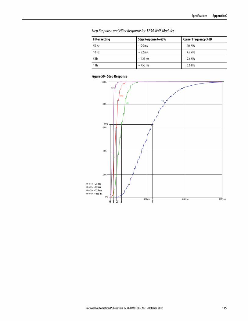
Specifications Appendix C
Step Response and Filter Response for 1734-IE4S Modules
Figure 50 - Step Response
Filter Setting Step Response to 63% Corner Frequency-3 dB
50 Hz ~ 25 ms 10.2 Hz
10 Hz ~ 72 ms 4.75 Hz
5 Hz ~ 125 ms 2.62 Hz
1 Hz ~ 450 ms 0.68 Hz
50 Hz
10 Hz
5 Hz1 Hz
100%
80%
60%63%
40%
400 ms 800 ms 1200 ms
20%
0%
0 1 2 3 4
0 ->1= ~25 ms0 ->2= ~72 ms0 ->3= ~125 ms0 ->4= ~450 ms
Rockwell Automation Publication 1734-UM013K-EN-P - October 2015 175

Appendix C Specifications
Figure 51 - Frequency Response of Current Input with Filter = 1 Hz
Figure 52 - Frequency Response of Current Input with Filter = 5 Hz
0.01 0.10 1.00 10.00 100.00 10000.001000.00
-30
-20
-10
-40
-70
-80
-60
-50
-90
Frequency (Hz)
Freq
uenc
y Res
pons
e (dB
)
ADC resolution = -72.2 dB
0.01 0.10 1.00 10.00 100.00 10000.001000.00
-30
-20
-10
-40
-70
-80
-60
-50
-90
Frequency (Hz)
Freq
uenc
y Res
pons
e (dB
)
ADC resolution = -72.2 dB
176 Rockwell Automation Publication 1734-UM013K-EN-P - October 2015

Specifications Appendix C
Figure 53 - Frequency Response of Current Input with Filter = 10 Hz
Figure 54 - Frequency Response of Current Input with Filter = 50 Hz
0.01 0.10 1.00 10.00 100.00 10000.001000.00
-30
-20
-10
0
-40
-70
-60
-50
-80
Frequency (Hz)
Freq
uenc
y Res
pons
e (dB
)
ADC resolution = -72.2 dB
0.01 0.10 1.00 10.00 100.00 10000.001000.00
-30
-20
-10
-40
-70
-60
-50
-80
Frequency (Hz)
Freq
uenc
y Res
pons
e (dB
)
ADC resolution = -72.2 dB
0.01 0.10 1.00 10.00 100.00 10000.001000.00
-30
-20
-10
-40
-70
-60
-50
-80
ADC resolution = -72.2 dB
Rockwell Automation Publication 1734-UM013K-EN-P - October 2015 177

Appendix C Specifications
Figure 55 - Frequency Response of Voltage Input with Filter = 1 Hz
Figure 56 - Frequency Response of Voltage Input with Filter = 5 Hz
0.01 0.10 1.00 10.00 100.00 10000.001000.00
-30
-20
-10
0
-40
-70
8 0
-60
-50
-90
Frequency (Hz)
Freq
uenc
y Res
pons
e (dB
)
ADC resolution = -72.2 dB
0.01 0.10 1.00 10.00 100.00 10000.001000.00
-30
-20
-10
0
-40
-70
8 0
-60
-50
-90
Frequency (Hz)
Freq
uenc
y Res
pons
e (dB
)
ADC resolution = -72.2 dB
178 Rockwell Automation Publication 1734-UM013K-EN-P - October 2015

Specifications Appendix C
Figure 57 - Frequency Response of Voltage Input with Filter = 10 Hz
Figure 58 - Frequency Response of Voltage Input with Filter = 50 Hz
0.01 0.10 1.00 10.00 100.00 10000.001000.00
-30
-20
-10
0
-40
-70
-60
-50
-80
Frequency (Hz)
Freq
uenc
y Res
pons
e (dB
)
ADC resolution = -72.2 dB
0.01 0.10 1.00 10.00 100.00 10000.001000.00
-30
-20
-10
0
-40
-70
-60
-50
-80
Frequency (Hz)
Freq
uenc
y Res
pons
e (dB
)
ADC resolution = -72.2 dB
Rockwell Automation Publication 1734-UM013K-EN-P - October 2015 179

Appendix C Specifications
Drift and Temperature
In Current mode, the accuracy drift of the 1734-IE4S module is very dependent on the temperature of the module and the amount of current being measured. As shown in Figure 59 below, the drift of the module increases greatly when currents above 16 mA are measured. To help preserve the accuracy of the1734-IE4S module in Current mode, choose a sensor for your application that can operate in the middle of its range and not at the outer limits.
Figure 59 - Accuracy Drift vs. Temperature (Current mode)
Temperature (°C)
Drift (%/°C)
180 Rockwell Automation Publication 1734-UM013K-EN-P - October 2015

Specifications Appendix C
Technical Specifications for Series B Modules
Safety Digital Input Module Specifications
Attribute 1734-IB8S Series B
Safety Input
Inputs per module 8
Input type Current sinking
Voltage, on-state input 11…30V DC, 3.5 mA @ 40 °C (104 °F), Class 2
11…28.8V DC, 3.5 mA @ 55 °C (131 °F), Class 2
1734-IB8S Series B temperature vs. safety input voltage (max) derating for both horizontal and vertical installations
Voltage, off-state input, max 5V DC
Current, on-state input, min 3.3 mA
Current, off-state, max 1.3 mA
IEC 61131-2 (input type) Type 3
Reaction time <16.2 ms
Pulse Test Output
Output type Current sourcing
Number of sources (T0, T1M, T2, T3M) 4
Test output current (each output point) 0.7 A @ 40 °C (104 °F)
0.5 A @ 55 °C (131 °F)
1734-IB8S Series B temperature vs. current per test output point derating for both horizontal and vertical installations
Aggregate current of test outputs per module 2.8 A @ 40 °C (104 °F)
0.55 A @ 55 °C (131 °F)
30V
-20 °C(-4 °F)
40 °C(104 °F)
55 °C(131 °F)
28.8V
0.7 A
-20 °C(-4 °F)
40 °C(104 °F)
55 °C(131 °F)
0.5 A
Rockwell Automation Publication 1734-UM013K-EN-P - October 2015 181

Appendix C Specifications
1734 -IB8S Series B temperature vs. aggregate current per module derating for both horizontal and vertical installations
Pulse width 525 s
Pulse period 144 ms
Maximum field capacitance limit permitted per test output
100 nF
Current, max (when used to control muting lamp) 25 mA (to avoid fault when used as a muted lamp output)
Current, min (when used to control muting lamp) 5 mA (at which fault indication is generated when used as a muted lamp output)
Residual voltage, max 0.3V
Output leakage current, max 0.1 mA
Short circuit protection Yes
POINTBus
POINTBus current, max 110 mA
Power dissipation, max (1) 3.0 W
Thermal dissipation, max 10.25 BTU/hr
Power dissipation, typical(2) 2.25 W
Isolation Voltage 50V (continuous), Basic Insulation Type between field side and system.
No isolation between individual channels.
Type tested at 500V AC for 60 s.
Power bus, operating supply voltage 24V DC nom, Class 2
Power bus, operating voltage range 19.2…28.8V DC, Class 2
Power bus current (no load), max 25 mA
Attribute 1734-IB8S Series B
2.8 A
-20 °C(-4 °F)
40 °C(104 °F)
55 °C(131 °F)
0.55 A
182 Rockwell Automation Publication 1734-UM013K-EN-P - October 2015
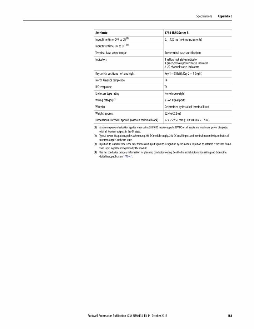
Specifications Appendix C
Input filter time, OFF to ON(3) 0…126 ms (in 6 ms increments)
Input filter time, ON to OFF(2)
Terminal base screw torque See terminal base specifications
Indicators 1 yellow lock status indicator1 green/yellow power status indicator8 I/O channel status indicators
Keyswitch positions (left and right) Key 1 = 8 (left); Key 2 = 1 (right)
North America temp code T4
IEC temp code T4
Enclosure type rating None (open-style)
Wiring category(4) 2 - on signal ports
Wire size Determined by installed terminal block
Weight, approx. 62.4 g (2.2 oz)
Dimensions (HxWxD), approx. (without terminal block) 77 x 25 x 55 mm (3.03 x 0.98 x 2.17 in.)
(1) Maximum power dissipation applies when using 28.8V DC module supply, 30V DC on all inputs and maximum power dissipated
with all four test outputs in the ON state.
(2) Typical power dissipation applies when using 24V DC module supply, 24V DC on all inputs and nominal power dissipated with all
four test outputs in the ON state.
(3) Input off-to-on filter time is the time from a valid input signal to recognition by the module. Input on-to-off time is the time from a
valid input signal to recognition by the module.
(4) Use this conductor category information for planning conductor routing. See the Industrial Automation Wiring and Grounding
Guidelines, publication 1770-4.1.
Attribute 1734-IB8S Series B
Rockwell Automation Publication 1734-UM013K-EN-P - October 2015 183

Appendix C Specifications
Safety Digital Output Module Specifications
Attribute 1734-OB8S Series B
Safety Output
Outputs per module 8
Output type Current sourcing
Output current (each output point), max 1 A @ 40 °C (104 °F)
0.5 A @ 55 °C (131 °F)
1734-OB8S Series B temperature vs. current per output point � derating for both horizontal and vertical installations
Aggregate current of outputs per module(1) 8 A (4 A per terminal base) @ 40 °C (104 °F)
2A (1A per terminal base) @ 55 °C (131 °F)
1734-OB8S Series B temperature vs. aggregate current per module derating for both horizontal and vertical installations(1)
Pulse width 475 s
Pulse period 575 ms
Maximum field capacitance limit permitted per output 950 nF
On-state voltage drop 0.165V
Leakage current, max 0.1 mA
Short-circuit detection Yes (short high and low and cross-circuit detect)
Short-circuit protection Electronic
Reaction time <6.2 ms
POINTBus
POINTBus current, max 125 mA
Power dissipation, max(2) 3.5 W
Thermal dissipation, max 11.96 BTU/hr
Power dissipation, typical(3) 2.5 W
Isolation voltage 50V (continuous), Basic Insulation Type between field side and systemNo isolation between individual channelsType tested at 860V AC DC for 60 s
Power bus, operating supply voltage 24V DC nom, Class 2
1 A
0.5 A
-20 °C(-4 °F)
40 °C(104 °F)
55 °C(131 °F)
8 A
2 A
-20 °C(-4 °F)
40 °C(104 °F)
55 °C(131 °F)
184 Rockwell Automation Publication 1734-UM013K-EN-P - October 2015
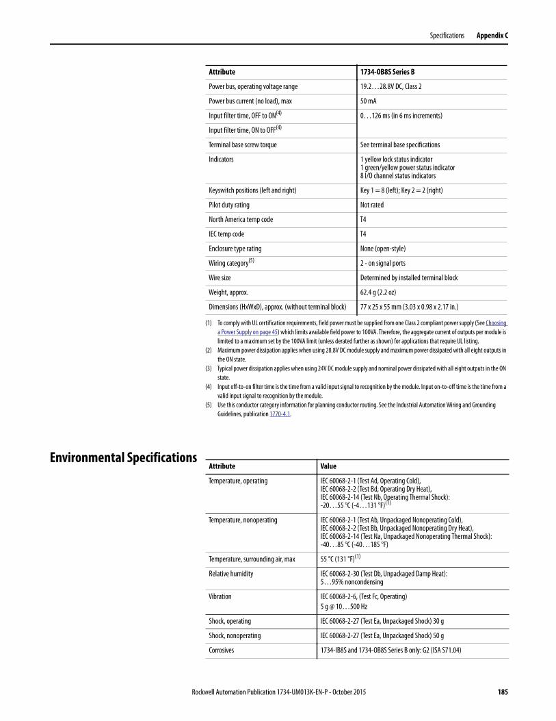
Specifications Appendix C
Environmental Specifications
Power bus, operating voltage range 19.2…28.8V DC, Class 2
Power bus current (no load), max 50 mA
Input filter time, OFF to ON(4) 0…126 ms (in 6 ms increments)
Input filter time, ON to OFF(4)
Terminal base screw torque See terminal base specifications
Indicators 1 yellow lock status indicator1 green/yellow power status indicator8 I/O channel status indicators
Keyswitch positions (left and right) Key 1 = 8 (left); Key 2 = 2 (right)
Pilot duty rating Not rated
North America temp code T4
IEC temp code T4
Enclosure type rating None (open-style)
Wiring category(5) 2 - on signal ports
Wire size Determined by installed terminal block
Weight, approx. 62.4 g (2.2 oz)
Dimensions (HxWxD), approx. (without terminal block) 77 x 25 x 55 mm (3.03 x 0.98 x 2.17 in.)
(1) To comply with UL certification requirements, field power must be supplied from one Class 2 compliant power supply (See Choosing
a Power Supply on page 45) which limits available field power to 100VA. Therefore, the aggregate current of outputs per module is
limited to a maximum set by the 100VA limit (unless derated further as shown) for applications that require UL listing.
(2) Maximum power dissipation applies when using 28.8V DC module supply and maximum power dissipated with all eight outputs in
the ON state.
(3) Typical power dissipation applies when using 24V DC module supply and nominal power dissipated with all eight outputs in the ON
state.
(4) Input off-to-on filter time is the time from a valid input signal to recognition by the module. Input on-to-off time is the time from a
valid input signal to recognition by the module.
(5) Use this conductor category information for planning conductor routing. See the Industrial Automation Wiring and Grounding
Guidelines, publication 1770-4.1.
Attribute 1734-OB8S Series B
Attribute Value
Temperature, operating IEC 60068-2-1 (Test Ad, Operating Cold),IEC 60068-2-2 (Test Bd, Operating Dry Heat),IEC 60068-2-14 (Test Nb, Operating Thermal Shock):-20…55 °C (-4…131 °F)(1)
Temperature, nonoperating IEC 60068-2-1 (Test Ab, Unpackaged Nonoperating Cold),IEC 60068-2-2 (Test Bb, Unpackaged Nonoperating Dry Heat),IEC 60068-2-14 (Test Na, Unpackaged Nonoperating Thermal Shock):-40…85 °C (-40…185 °F)
Temperature, surrounding air, max 55 °C (131 °F)(1)
Relative humidity IEC 60068-2-30 (Test Db, Unpackaged Damp Heat):5…95% noncondensing
Vibration IEC 60068-2-6, (Test Fc, Operating)
5 g @ 10…500 Hz
Shock, operating IEC 60068-2-27 (Test Ea, Unpackaged Shock) 30 g
Shock, nonoperating IEC 60068-2-27 (Test Ea, Unpackaged Shock) 50 g
Corrosives 1734-IB8S and 1734-OB8S Series B only: G2 (ISA S71.04)
Rockwell Automation Publication 1734-UM013K-EN-P - October 2015 185
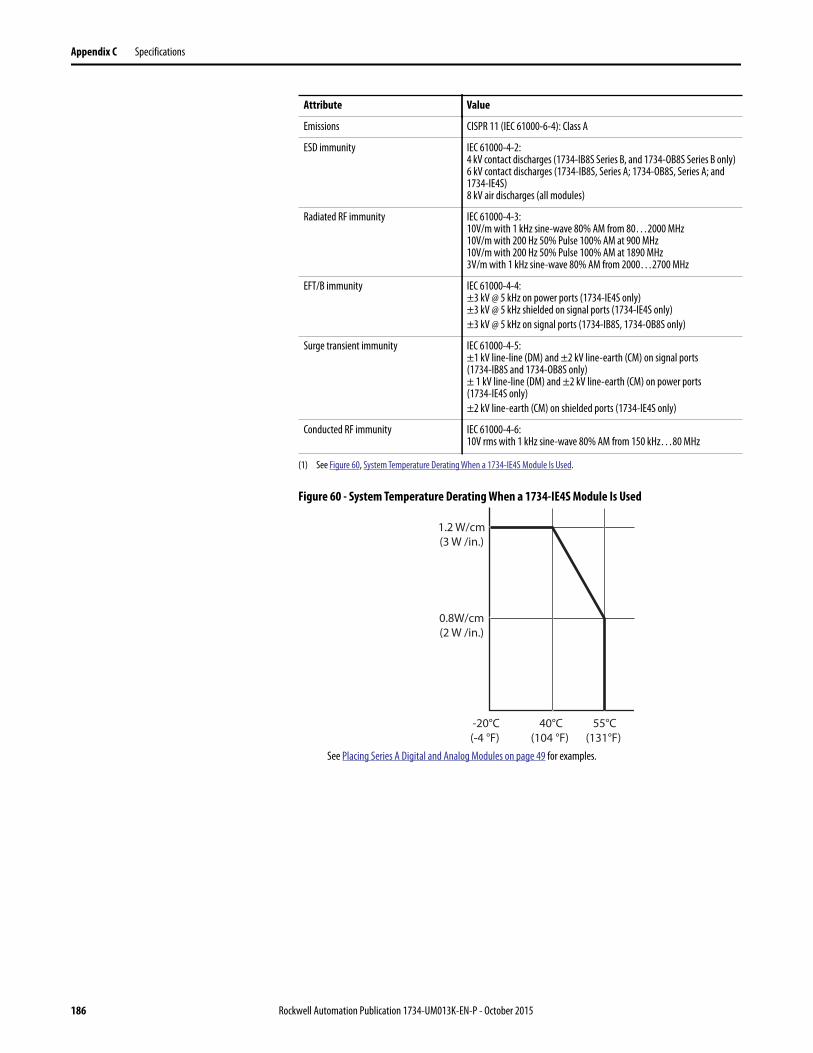
Appendix C Specifications
Figure 60 - System Temperature Derating When a 1734-IE4S Module Is Used
Emissions CISPR 11 (IEC 61000-6-4): Class A
ESD immunity IEC 61000-4-2:4 kV contact discharges (1734-IB8S Series B, and 1734-OB8S Series B only) 6 kV contact discharges (1734-IB8S, Series A; 1734-OB8S, Series A; and 1734-IE4S) 8 kV air discharges (all modules)
Radiated RF immunity IEC 61000-4-3:10V/m with 1 kHz sine-wave 80% AM from 80…2000 MHz10V/m with 200 Hz 50% Pulse 100% AM at 900 MHz10V/m with 200 Hz 50% Pulse 100% AM at 1890 MHz3V/m with 1 kHz sine-wave 80% AM from 2000…2700 MHz
EFT/B immunity IEC 61000-4-4:±3 kV @ 5 kHz on power ports (1734-IE4S only)±3 kV @ 5 kHz shielded on signal ports (1734-IE4S only)
±3 kV @ 5 kHz on signal ports (1734-IB8S, 1734-OB8S only)
Surge transient immunity IEC 61000-4-5:±1 kV line-line (DM) and ±2 kV line-earth (CM) on signal ports (1734-IB8S and 1734-OB8S only)± 1 kV line-line (DM) and ±2 kV line-earth (CM) on power ports (1734-IE4S only)
±2 kV line-earth (CM) on shielded ports (1734-IE4S only)
Conducted RF immunity IEC 61000-4-6:10V rms with 1 kHz sine-wave 80% AM from 150 kHz…80 MHz
(1) See Figure 60, System Temperature Derating When a 1734-IE4S Module Is Used.
Attribute Value
1.2 W/cm(3 W /in.)
0.8W/cm(2 W /in.)
-20°C(-4 °F)
40°C(104 °F)
55°C(131°F)
See Placing Series A Digital and Analog Modules on page 49 for examples.
186 Rockwell Automation Publication 1734-UM013K-EN-P - October 2015

Specifications Appendix C
Certifications POINT Guard I/O™ modules have the following certifications, when product is marked.
1734-IE4S, 1734-IB8S Series B, and 1734-OB8S Series B modules are certified for use to help meet the following:
• NFPA 85 - Burners• NFPA 86 - Furnaces• NFPA 72 – Fire Alarms
1734-IE4S, 1734-IB8S, and 1734-OB8S are certified to help meet NFPA79 – Electrical Installation of Industrial Machinery.
1734-IE4S, 1734-IB8S Series B, and 1734-OB8S Series B modules are certified to help meet the following: EN14459 and EN13611 (suitable for use in Group 1, Class C burner control system applications).
Legislations and Standards Familiarize yourself with related legislation and standards information. Relevant international standards include the following:
• IEC 61508 (SIL 1…3)• IEC 61131-6• IEC 60204-1• IEC 62061• ISO 13849-1
Certification(when product is marked)(1)
(1) See the Product Certification link at http://www.ab.com for Declaration of Conformity, Certificates, and other certification details.
1734-IB8S, 1734-OB8S, 1734-IE4S
c-UL-us Listed Industrial Control Equipment, certified for US and Canada.See UL File E65584.
UL Listed for Class I, Division 2, Group A,B,C,D Hazardous Locations, certified for U.S. and Canada. See UL File E194810.
CE European Union 2004/108/EC EMC Directive, compliant with:• EN 61326-1; Meas./Control/Lab., Industrial Requirements• EN 61000-6-2; Industrial Immunity• EN6100-6-4; Industrial Emissions• EN 61131-2; Programmable Controllers (Clause 8, Zone A & B)
Ex European Union 94/9/EC ATEX Directive, compliant with:• EN 60079-15; Potentially Explosive Atmospheres, Protection ‘n’• EN 60079-0; General Requirements II 3 G Ex nA IIC T4 Gc X
RCM Australian Radiocommunications Act compliant with: EN 61000-6-4; Industrial Emissions
Functional Safety Certified by TÜV Rheinland(2): capable of SIL CL 3 (IEC 61508, IEC 62061) and PLe/Cat. 4 (ISO13849-1)
(2) When used with specified Firmware Revisions.
ODVA ODVA conformance tested to CIP Safety on DeviceNet specifications
KC Korean Registration of Broadcasting and Communications Equipment, compliant with:• Article 58-2 of Radio Waves Act, Clause 3
Rockwell Automation Publication 1734-UM013K-EN-P - October 2015 187

Appendix C Specifications
Notes:
188 Rockwell Automation Publication 1734-UM013K-EN-P - October 2015

Appendix D
Safety Data
This appendix lists calculated values for probability of failure on demand (PFD), probability of failure per hour (PFH), and mean time to failure (MTTF). PFD and PFH calculations comply with IEC61508, edition 2, 2010.
Calculated values of probability of failure on demand and probability of failure per hour appear in the table. Both must be calculated for the devices within the system to comply with the SIL level required for application.
You must be responsible for following the requirements of ISO 13849-1:2008, to assess performance levels in their safety system.
Every I/O module must be functionally tested by individually toggling each input point and also verify that the controller detects it within the proof test interval.
Additionally, each output point must be individually toggled by the controller and user-verified that the output point changes state.
For more information, see these publications.
Resource Description
GuardLogix® 5570 Controller Systems Safety Reference Manual, publication 1756-RM099
Provides information on safety application requirements for GuardLogix 5570 controllers in Studio 5000 Logix Designer® projects.
GuardLogix Controller Systems Safety Reference Manual, publication 1756-RM093
Provides information on safety application requirements for GuardLogix 5560 and 5570 controllers in RSLogix™ 5000 projects.
Rockwell Automation Publication 1734-UM013K-EN-P - October 2015 189
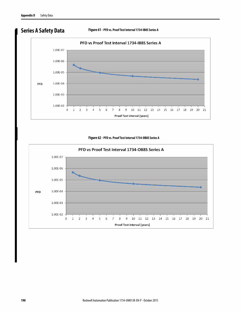
Appendix D Safety Data
Series A Safety Data Figure 61 - PFD vs. Proof Test Interval 1734-IB8S Series A
Figure 62 - PFD vs. Proof Test Interval 1734-OB8S Series A
190 Rockwell Automation Publication 1734-UM013K-EN-P - October 2015

Safety Data Appendix D
Figure 63 - PFD vs. Proof Test Interval 1734-IE4S Series A Single Channel
Figure 64 - PFD vs. Proof Test Interval 1734-IE4S Series A Dual Channel
Rockwell Automation Publication 1734-UM013K-EN-P - October 2015 191
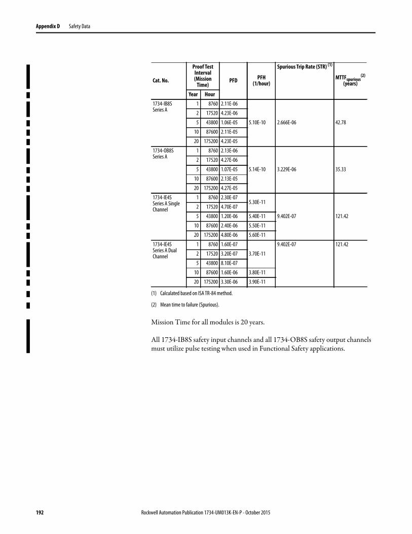
Appendix D Safety Data
Mission Time for all modules is 20 years.
All 1734-IB8S safety input channels and all 1734-OB8S safety output channels must utilize pulse testing when used in Functional Safety applications.
Cat. No.
Proof Test Interval(Mission
Time)PFD PFH
(1/hour)
Spurious Trip Rate (STR) (1)
(1) Calculated based on ISA TR-84 method.
MTTFspurious(2)
(years)
(2) Mean time to failure (Spurious).
Year Hour
1734-IB8S Series A
1 8760 2.11E-06
5.10E-10 2.666E-06 42.78
2 17520 4.23E-06
5 43800 1.06E-05
10 87600 2.11E-05
20 175200 4.23E-05
1734-OB8S Series A
1 8760 2.13E-06
5.14E-10 3.229E-06 35.33
2 17520 4.27E-06
5 43800 1.07E-05
10 87600 2.13E-05
20 175200 4.27E-05
1734-IE4S Series A Single Channel
1 8760 2.30E-075.30E-11
9.402E-07 121.42
2 17520 4.70E-07
5 43800 1.20E-06 5.40E-11
10 87600 2.40E-06 5.50E-11
20 175200 4.80E-06 5.60E-11
1734-IE4S Series A Dual Channel
1 8760 1.60E-07
3.70E-11
9.402E-07 121.42
2 17520 3.20E-07
5 43800 8.10E-07
10 87600 1.60E-06 3.80E-11
20 175200 3.30E-06 3.90E-11
192 Rockwell Automation Publication 1734-UM013K-EN-P - October 2015

Safety Data Appendix D
Series B Safety Data Figure 65 - PFD vs. Proof Test Interval 1734-IB8S Series B Single Channel
Figure 66 - PFD vs. Proof Test Interval 1734-OB8S Series B Single Channel(1)
(1) 1734-OB8S single channel mode is only certified for functional safety applications with Process Safety Times ≥ 600 msec OR with Demand Rates ≤ 1 Demand per Minute.
Rockwell Automation Publication 1734-UM013K-EN-P - October 2015 193

Appendix D Safety Data
Figure 67 - PFD vs. Proof Test Interval 1734-IB8S Series B Dual Channel
Figure 68 - PFD vs. Proof Test Interval 1734-OB8S Series B Dual Channel
194 Rockwell Automation Publication 1734-UM013K-EN-P - October 2015

Safety Data Appendix D
Mission Time for all modules is 20 years.
All 1734-IB8S safety input channels and all 1734-OB8S safety output channels must utilize pulse testing when used in Functional Safety applications.
Catalog Number
Proof Test Interval (Mission Time)
PFD PFH (1/hour) Spurious Trip Rate (STR)(2)
(2) Calculated based on ISA TR-84 method.
MTTF spurious(years)(3)
(3) Mean time to failure (spurious).
Year Hour
1734-IB8SSeries B
Single Channel
1 8760 2.42E-06 5.61E-10 2.709E-06 42.14
2 17520 4.85E-06
5 43800 1.21-05
10 87600 2.43E-05
20 175200 4.89E-05
1734-OB8SSeries B(1) Single Channel
(1) 1734-OB8S single channel mode is only certified for functional safety applications with process safety times ≥ 600 ms or with
demand rates ≤ 1 demand per minute.
1 8760 2.02E-05 4.62E-09 3.243E-06 35.20
2 17520 4.04E-05
5 43800 1.01E-04
10 87600 2.02E-04
20 175200 4.04E-04
1734-IB8SSeries B
Dual Channel
1 8760 4.89E-07 1.20E-10 2.709E-06 42.14
2 17520 9.80E-07
5 43800 2.47E-06
10 87600 5.00E-06
20 175200 1.02E-05
1734-0B8SSeries B
Dual Channel
1 8760 4.89E-07 1.20E-10 3.243E-06 35.20
2 17520 9.81E-07
5 43800 2.47E-06
10 87600 5.00E-06
20 175200 1.02E-05
Rockwell Automation Publication 1734-UM013K-EN-P - October 2015 195
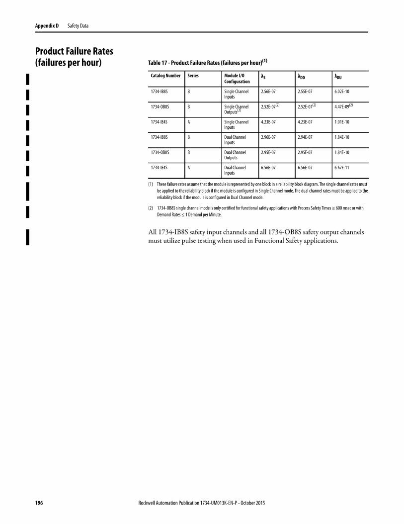
Appendix D Safety Data
Product Failure Rates (failures per hour)
All 1734-IB8S safety input channels and all 1734-OB8S safety output channels must utilize pulse testing when used in Functional Safety applications.
Table 17 - Product Failure Rates (failures per hour)(1)
(1) These failure rates assume that the module is represented by one block in a reliability block diagram. The single channel rates must
be applied to the reliability block if the module is configured in Single Channel mode. The dual channel rates must be applied to the
reliability block if the module is configured in Dual Channel mode.
Catalog Number Series Module I/O Configuration
λS λDD λDU
1734-IB8S B Single Channel Inputs
2.56E-07 2.55E-07 6.02E-10
1734-OB8S B Single Channel Outputs(2)
(2) 1734-OB8S single channel mode is only certified for functional safety applications with Process Safety Times ≥ 600 msec or with
Demand Rates ≤ 1 Demand per Minute.
2.52E-07(2) 2.52E-07(2) 4.47E-09(2)
1734-IE4S A Single Channel Inputs
4.23E-07 4.23E-07 1.01E-10
1734-IB8S B Dual Channel Inputs
2.96E-07 2.94E-07 1.84E-10
1734-OB8S B Dual Channel Outputs
2.95E-07 2.95E-07 1.84E-10
1734-IE4S A Dual Channel Inputs
6.56E-07 6.56E-07 6.67E-11
196 Rockwell Automation Publication 1734-UM013K-EN-P - October 2015

Appendix E
Configuration Parameters
This appendix lists parameters that can be configured via the Logix Designer application.
Topic Page
Table 18 Safety Digital Input Parameters 197
Table 19 Test Output Parameters 198
Table 20 Safety Digital Output Parameters 198
Table 21 Safety Analog Input Parameters 198
Table 18 - Safety Digital Input Parameters
Parameter Name(1) Value Description Default
x Input Delay Time Off -> On
0…126 ms (in increments of 6 ms)
Filter time for OFF to ON transition.
x Input Delay TimeOn -> Off
0…126 ms (in increments of 6 ms)
Filter time for ON to OFF transition.
x Input Point Mode Not Used External input device is not connected.
Safety Pulse Test Use with a contact output device and in combination with a test output. With the use of this setting, short-circuits between input signal lines and the power supply (positive side) and short-circuits between input signal lines can be detected.
Safety A solid-state output safety sensor is connected.
Standard A standard device, such as a reset switch, is connected.
x Safety Input Test Source Not Used The test output that is used with the input.
Test Output 0
Test Output 1
Test Output 2
Test Output 3
x Input Point Operation Type Single Channel Use as single channel.
Dual-channel Equivalent Use as dual-channel. Normal when both channels are ON or OFF.
Dual-channel Complementary Use as dual-channel. Normal when one channel is ON and the other channel is OFF.
x Safety Input Error Latch Time 0…65,530 ms(in increments of 10 ms)
Safety input or test output errors are latched for this time. 1000 ms
(1) Parameters that are directly related to safety are marked with an x in the left column.
Rockwell Automation Publication 1734-UM013K-EN-P - October 2015 197

Appendix E Configuration Parameters
Table 19 - Test Output Parameters
Parameter Name(1) Value Description Default
x Test Output Mode Not Used An external device is not connected. Not Used
Standard The output is connected to a standard device.
Pulse Test A contact output device is connected. Use in combination with a safety input.
Power Supply The power supply of a Safety Sensor is connected. The voltage that is supplied to I/O power (V, G) is output from the test output terminal.
Muting Lamp Output (Terminal T1 or T3 only)
An indicator is connected and turned ON to detect broken lines in an external indicator.
Test Output Fault Action Clear OFF Action to perform when a communication error is detected. Clear OFF
Hold Last Data
(1) Parameters that are directly related to safety are marked with an x in the left column.
Table 20 - Safety Digital Output Parameters
Parameter Name(1) Value Description Default
x Output Point Mode Not Used An external output device is not connected. Not Used
Safety When the output is ON, the test pulse is not output (remains ON).
Safety Pulse Test With use of this function, short-circuits between output signal lines and the power supply (positive side) and short-circuits between output signal lines can be detected.
x Output Point Operation Type Single Channel Use as single channel. Dual-channel
Dual-channel Use as dual-channel. When both channels are normal, outputs can be turned ON.
x Safety Output Error Latch Time
0…65,530 ms(in increments of 10 ms)
Safety output errors are latched for this time. 1000 ms
(1) Parameters that are directly related to safety are marked with an x in the left column.
Parameter Name Value Description Default
Test Output Idle State(1) Clear OFF or Keep Output Data Definition of output data is in idle state. Clear OFF
(1) Set only through Explicit Messaging. See for Appendix B more information.
Table 21 - Safety Analog Input Parameters
Parameter Name(1) Value Description Default
x Input Point Mode Not Used External input device is not connected.
Not UsedSafety A solid-state safety sensor is connected.
Standard A device that is not used in the safety loop is connected.
Range ±10V
Input voltage range.
4…20 mA
0…5V
0…10V
±5V
4…20 mAInput current range.
0…20 mA
Tachometer Tachometer mode.
198 Rockwell Automation Publication 1734-UM013K-EN-P - October 2015
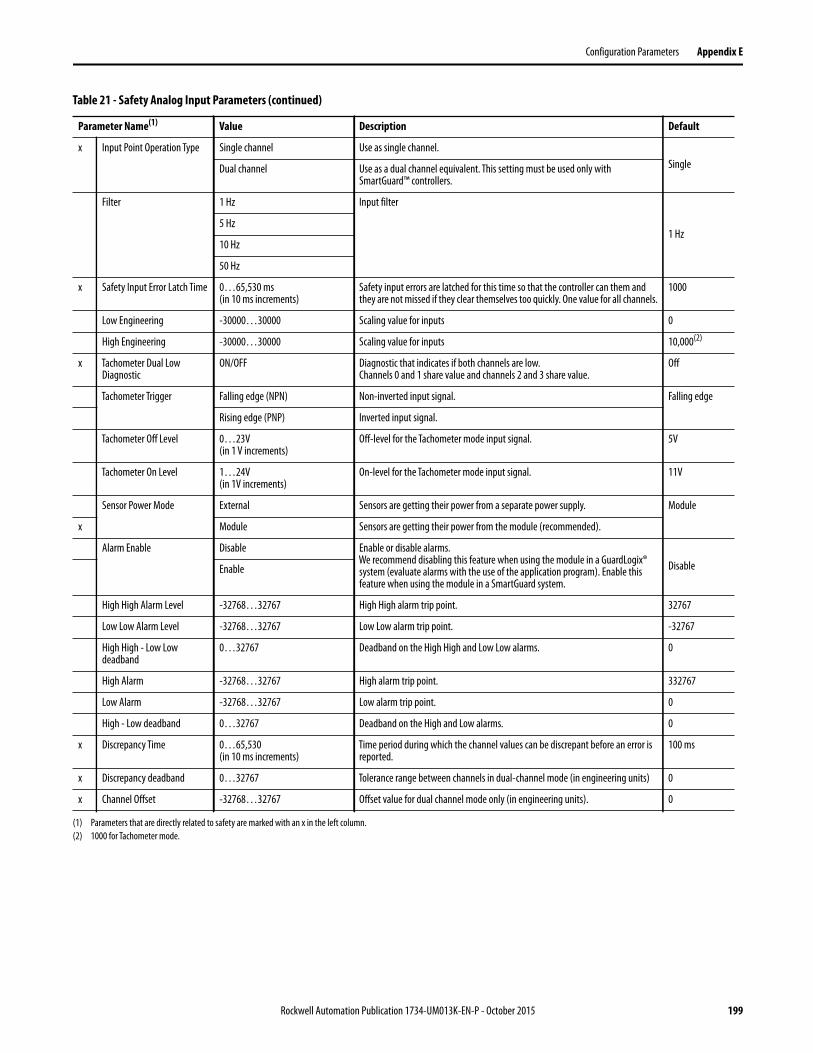
Configuration Parameters Appendix E
x Input Point Operation Type Single channel Use as single channel.
SingleDual channel Use as a dual channel equivalent. This setting must be used only with SmartGuard™ controllers.
Filter 1 Hz Input filter
1 Hz5 Hz
10 Hz
50 Hz
x Safety Input Error Latch Time 0…65,530 ms(in 10 ms increments)
Safety input errors are latched for this time so that the controller can them and they are not missed if they clear themselves too quickly. One value for all channels.
1000
Low Engineering -30000…30000 Scaling value for inputs 0
High Engineering -30000…30000 Scaling value for inputs 10,000(2)
x Tachometer Dual Low Diagnostic
ON/OFF Diagnostic that indicates if both channels are low.Channels 0 and 1 share value and channels 2 and 3 share value.
Off
Tachometer Trigger Falling edge (NPN) Non-inverted input signal. Falling edge
Rising edge (PNP) Inverted input signal.
Tachometer Off Level 0…23V(in 1 V increments)
Off-level for the Tachometer mode input signal. 5V
Tachometer On Level 1…24V(in 1V increments)
On-level for the Tachometer mode input signal. 11V
Sensor Power Mode External Sensors are getting their power from a separate power supply. Module
x Module Sensors are getting their power from the module (recommended).
Alarm Enable Disable Enable or disable alarms.We recommend disabling this feature when using the module in a GuardLogix® system (evaluate alarms with the use of the application program). Enable this feature when using the module in a SmartGuard system.
DisableEnable
High High Alarm Level -32768…32767 High High alarm trip point. 32767
Low Low Alarm Level -32768…32767 Low Low alarm trip point. -32767
High High - Low Low deadband
0…32767 Deadband on the High High and Low Low alarms. 0
High Alarm -32768…32767 High alarm trip point. 332767
Low Alarm -32768…32767 Low alarm trip point. 0
High - Low deadband 0…32767 Deadband on the High and Low alarms. 0
x Discrepancy Time 0…65,530(in 10 ms increments)
Time period during which the channel values can be discrepant before an error is reported.
100 ms
x Discrepancy deadband 0…32767 Tolerance range between channels in dual-channel mode (in engineering units) 0
x Channel Offset -32768…32767 Offset value for dual channel mode only (in engineering units). 0
(1) Parameters that are directly related to safety are marked with an x in the left column.
(2) 1000 for Tachometer mode.
Table 21 - Safety Analog Input Parameters (continued)
Parameter Name(1) Value Description Default
Rockwell Automation Publication 1734-UM013K-EN-P - October 2015 199

Appendix E Configuration Parameters
Notes:
200 Rockwell Automation Publication 1734-UM013K-EN-P - October 2015

Appendix F
I/O Assemblies
Input Assemblies
Topic Page
Input Assemblies 201
Output Assemblies 202
Analog Input Assemblies 202
Configuration Assemblies 204
Using Data from Modules Configured Via the Generic Profile 210
Table 22 - 1734-IB8S Input Assemblies
Instance Decimal (hex)
Connection Type
Byte Bit 7 Bit 6 Bit 5 Bit 4 Bit 3 Bit 2 Bit 1 Bit 0
516 (204 h) Safety and Standard
0 Safety Input 7
Safety Input 6
Safety Input 5 Safety Input 4 Safety Input 3 Safety Input 2 Safety Input 1 Safety Input 0
548 (224 h) Safety Only 0 Safety Input 7
Safety Input 6
Safety Input 5 Safety Input 4 Safety Input 3 Safety Input 2 Safety Input 1 Safety Input 0
1 Safety Input 7 Status
Safety Input 6 Status
Safety Input 5 Status
Safety Input 4 Status
Safety Input 3 Status
Safety Input 2 Status
Safety Input 1 Status
Safety Input 0 Status
768 (300 h) Standard Only 0 Reserved Input Power Error
788 (314 h) Safety and Standard
0 Safety Input 7
Safety Input 6
Safety Input 5 Safety Input 4 Safety Input 3 Safety Input 2 Safety Input 1 Safety Input 0
1 Combined Safety Input Status
Reserved Input Power Error(1)
Reserved Reserved Reserved Muting Lamp 3 Status
Muting Lamp 1 Status
820 (334 h) Safety and Standard
0 Safety Input 7
Safety Input 6
Safety Input 5 Safety Input 4 Safety Input 3 Safety Input 2 Safety Input 1 Safety Input 0
1 Safety Input 7 Status
Safety Input 6 Status
Safety Input 5 Status
Safety Input 4 Status
Safety Input 3 Status
Safety Input 2 Status
Safety Input 1 Status
Safety Input 0 Status
2 Reserved Input Power Error(1)
Reserved Muting Lamp 3 Status
Muting Lamp 1 Status
868 (364 h) Safety and Standard
0 Safety Input 7 Safety Input 6 Safety Input 5 Safety Input 4 Safety Input 3 Safety Input 2 Safety Input 1 Safety Input 0
1 Safety Input 7 Status
Safety Input 6 Status
Safety Input 5 Status
Safety Input 4 Status
Safety Input 3 Status
Safety Input 2 Status
Safety Input 1 Status
Safety Input 0 Status
2 Reserved Test Output 3 Status
Test Output 2 Status
Test Output 1 Status
Test Output 0 Status
3 Reserved Input Power Error(1)
Reserved Muting Lamp 3 Status
Muting Lamp 1Status
899 (383 h) Standard 0 Reserved Input Power Error
1 Reserved Test Output 3 Status
Test Output 2 Status
Test Output 1 Status
Test Output 0 Status
(1) This data is diagnostic only and does not have safety integrity.
Rockwell Automation Publication 1734-UM013K-EN-P - October 2015 201

Appendix F I/O Assemblies
Output Assemblies
Analog Input Assemblies
Table 23 - 1734-OB8S Input Assemblies
Instance Decimal (hex)
Connection Type
Byte Bit 7 Bit 6 Bit 5 Bit 4 Bit 3 Bit 2 Bit 1 Bit 0
580 (244 h) Safety and Standard
0 Safety Output 7 Status
Safety Output 6 Status
Safety Output 5 Status
Safety Output 4 Status
Safety Output 3 Status
Safety Output 2 Status
Safety Output 1 Status
Safety Output 0 Status
1028 (404 h) Safety and Standard
0 Safety Output 7 Status
Safety Output 6 Status
Safety Output 5 Status
Safety Output 4 Status
Safety Output 3 Status
Safety Output 2 Status
Safety Output 1 Status
Safety Output 0 Status
1 Safety Output Monitor 7
Safety Output Monitor 6
Safety Output Monitor 5
Safety Output Monitor 4
Safety Output Monitor 3
Safety Output Monitor 2
Safety Output Monitor 1
Safety Output Monitor 0
1044 (414 h) Safety and Standard
0 Safety Output Monitor 7
Safety Output Monitor 6
Safety Output Monitor 5
Safety Output Monitor 4
Safety Output Monitor 3
Safety Output Monitor 2
Safety Output Monitor 1
Safety Output Monitor 0
1 Reserved Combined Output Status
Reserved Output Power Error(1)
Reserved
(1) This data is diagnostic only and does not have safety integrity.
Table 24 - Output Assemblies for all POINT Guard I/O™ Modules
Instance Decimal (hex)
Module Connection Type
Byte Bit 7 Bit 6 Bit 5 Bit 4 Bit 3 Bit 2 Bit 1 Bit 0
33 (21 h) 1734-IB8S Safety(1) 0Reserved
Standard Output 3
Standard Output 2
Standard Output 1
Standard Output 0
564 (234 h) 1734-OB8S Safety Only 0 Safety Output 7
Safety Output 6
Safety Output 5
Safety Output 4
Safety Output 3
Safety Output 2
Safety Output 1
Safety Output 0
770 (302 h) 1734-IE4S Safety 0 Reserved Reserved Reserved Reserved Reset Tach 3(2)
Reset Tach 2(2)
Reset Tach 1(2)
Reset Tach 0(2)
(1) Only outputs 1 and 3 are configurable to Muting or Test Outputs. This assembly is accessible only over a Safety connection.
(2) When set (1), this bit specifies a reset of an overfrequency condition on the tachometer counter. Clear this bit to allow the tachometer channel to operate.
Table 25 - 1734-IE4S Input Assemblies
Instance Decimal (hex)
Connection Type
Byte High Byte Low Byte
402 (192 h)Safety and Standard
0, 1 Input 0 Input 0
2, 3 Input 1 Input 1
4, 5 Input 2 Input 2
6, 7 Input 3 Input 3
Bit 7 Bit 6 Bit 5 Bit 4 Bit 3 Bit 2 Bit 1 Bit 0
8 Reserved Reserved Reserved Reserved Ch 3 Input Status
Ch 2 Input Status
Ch 1 Input Status
Ch 0 Input Status
202 Rockwell Automation Publication 1734-UM013K-EN-P - October 2015

I/O Assemblies Appendix F
Instance Decimal (hex)
Connection Type
Byte High Byte Low Byte
786 (312 h)Safety and Standard
0, 1 Input 0 Input 0
2, 3 Input 1 Input 1
4, 5 Input 2 Input 2
6, 7 Input 3 Input 3
Bit 7 Bit 6 Bit 5 Bit 4 Bit 3 Bit 2 Bit 1 Bit 0
8 Reserved Reserved Reserved Reserved Ch 3 Input Status
Ch 2 Input Status
Ch 1 Input Status
Ch 0 Input Status
9
Alarms 0(1)
Reserved Tachometer Dual Low
Tachometer Underfrequency
Tachometer Overfrequency
Low Alarm Status
High Alarm Status
Low Low Alarm Status
High High Alarm Status
10
Alarms 1(1)
Reserved Tachometer Dual Low
Tachometer Underfrequency
Tachometer Overfrequency
Low Alarm Status
High Alarm Status
Low Low Alarm Status
High High Alarm Status
11
Alarms 2(1)
Reserved Tachometer Dual Low
Tachometer Underfrequency
Tachometer Overfrequency
Low Alarm Status
High Alarm Status
Low Low Alarm Status
High High Alarm Status
12
Alarms 3(1)
Reserved Tachometer Dual Low
Tachometer Underfrequency
Tachometer Overfrequency
Low Alarm Status
High Alarm Status
Low Low Alarm Status
High High Alarm Status
Instance Decimal (hex)
Connection Type
Byte High Byte Low Byte
802 (322 h)Safety and Standard
0, 1 Input 0 Input 0
2, 3 Input 1 Input 1
4, 5 Input 2 Input 2
6, 7 Input 3 Input 3
Bit 7 Bit 6 Bit 5 Bit 4 Bit 3 Bit 2 Bit 1 Bit 0
8 Ch 3Combined Alarm Status
Ch 2 Combined Alarm Status
Ch 1 Combined Alarm Status
Ch 0 Combined Alarm Status
Ch 3 Input Status
Ch 2 Input Status
Ch 1 Input Status
Ch 0 Input Status
9 Fault Reason 0
10 Fault Reason 1
11 Fault Reason 2
12 Fault Reason 3
13
Alarms 0(1)
Reserved Tachometer Dual Low
Tachometer Underfrequency
Tachometer Overfrequency
Low Alarm Status
High Alarm Status
Low Low Alarm Status
High High Alarm Status
14
Alarms 1(1)
Reserved Tachometer Dual Low
Tachometer Underfrequency
Tachometer Overfrequency
Low Alarm Status
High Alarm Status
Low Low Alarm Status
High High Alarm Status
15
Alarms 2(1)
Reserved Tachometer Dual Low
Tachometer Underfrequency
Tachometer Overfrequency
Low Alarm Status
High Alarm Status
Low Low Alarm Status
High High Alarm Status
16
Alarms 3(1)
Reserved Tachometer Dual Low
Tachometer Underfrequency
Tachometer Overfrequency
Low Alarm Status
High Alarm Status
Low Low Alarm Status
High High Alarm Status
17 Reserved Reserved Reserved Reserved Reserved Reserved Reserved Input Power
Instance Decimal (hex)
Connection Type
Byte Bit 7 Bit 6 Bit 5 Bit 4 Bit 3 Bit 2 Bit 1 Bit 0
930 (3A2h) Safety and Standard
0 Ch 3Combined Alarm Status
Ch 2 Combined Alarm Status
Ch 1 Combined Alarm Status
Ch 0 Combined Alarm Status
Ch 3 Input Status
Ch 2 Input Status
Ch 1 Input Status
Ch 0 Input Status
Table 25 - 1734-IE4S Input Assemblies (continued)
Rockwell Automation Publication 1734-UM013K-EN-P - October 2015 203

Appendix F I/O Assemblies
Configuration Assemblies See the appropriate table for 1734-IB8S, 1734-OB8S, and 1734-IE4S configuration assembly data.
Instance Decimal (hex)
Connection Type
Byte Bit 7 Bit 6 Bit 5 Bit 4 Bit 3 Bit 2 Bit 1 Bit 0
946 (3B2h)Safety and Standard
0Ch 3Combined Alarm Status
Ch 2 Combined Alarm Status
Ch 1 Combined Alarm Status
Ch 0 Combined Alarm Status
Ch 3 Input Status
Ch 2 Input Status
Ch 1 Input Status
Ch 0 Input Status
1
Alarms 0(1)
Reserved Tachometer Dual Low
Tachometer Underfrequency
Tachometer Overfrequency
Low Alarm Status
High Alarm Status
Low Low Alarm Status
High High Alarm Status
2
Alarms 1(1)
Reserved Tachometer Dual Low
Tachometer Underrange
Tachometer Overrange
Low Alarm Status
High Alarm Status
Low Low Alarm Status
High High Alarm Status
3
Alarms 2(1)
Reserved Tachometer Dual Low
Tachometer Underrange
Tachometer Overrange
Low Alarm Status
High Alarm Status
Low Low Alarm Status
High High Alarm Status
4
Alarms 3(1)
Reserved Tachometer Dual Low
Tachometer Underrange
Tachometer Overrange
Low Alarm Status
High Alarm Status
Low Low Alarm Status
High High Alarm Status
5 Reserved Reserved Reserved Reserved Reserved Reserved Reserved Input Power (1)
(1) 0 = fault; 1 = within range.
Table 25 - 1734-IE4S Input Assemblies (continued)
Table 26 - Configuration Assemblies for 1734-OB8S Output Modules
Instance Decimal (hex)
Byte Field Class (hex) Instance (decimal)
Attribute (decimal)
864 (360 h) 0 Safety Output Latch Error Time (low byte) 3B 0 8
1 Safety Output Latch Error Time (high byte)
2 Safety Output 0 Channel Mode 3B 1 6
3 Safety Output 1 Channel Mode 2
4 Safety Output 2 Channel Mode 3
5 Safety Output 3 Channel Mode 4
6 Safety Output 4 Channel Mode 5
7 Safety Output 5 Channel Mode 6
8 Safety Output 6 Channel Mode 7
9 Safety Output 7 Channel Mode 8
10 Dual-channel Safety Output 0 Mode 3F 1 3
11 Dual-channel Safety Output 1 Mode 2
12 Dual-channel Safety Output 2 Mode 3
13 Dual-channel Safety Output 3 Mode 4
204 Rockwell Automation Publication 1734-UM013K-EN-P - October 2015

I/O Assemblies Appendix F
Table 27 - Configuration Assemblies for 1734-IB8S Input Modules
Instance Decimal (hex)
Byte Field Class (hex) Instance (decimal)
Attribute (decimal)
864 (360 h) 0 Test Output 0 Mode 9 1 13
1 Test Output 1 Mode 2
2 Test Output 2 Mode 3
3 Test Output 3 Mode 4
4 Safety Input Latch Error Time (low byte) 3D 0 8
5 Safety Input Latch Error Time (high byte)
6 Safety Input 0 Off_On_Delay (low byte) 1 5
7 Safety Input 1 Off_On_Delay (high byte)
8 Safety Input 0 On_Off_Delay (low byte) 6
9 Safety Input 0 On_Off_Delay (high byte)
10 Safety Input 0 Channel Mode 8
11 Safety Input 0 Test Source 9
… Safety Input 1…6 Configuration Data … …
48 Safety Input 7 Off_On_Delay (low byte) 8 5
49 Safety Input 7 Off_On_Delay (high byte)
50 Safety Input On_Off_Delay (low byte) 6
51 Safety Input On_Off_Delay (high byte)
52 Safety Input 7 Channel Mode 8
53 Safety Input 7 Test Source 9
54 Dual-channel Safety Input 0 Mode 348 1 3
55 Pad Byte (0x00) … … …
56 Dual-channel Safety Input 0 Discrepancy Time (low byte) 348 1 5
57 Dual-channel Safety Input 0 Discrepancy Time (high byte)
… Dual-channel Safety Input 1…2 Configuration … … …
66 Dual-channel Safety Input 3 Mode 348 4 3
67 Pad Byte (0x00) … … …
68 Dual-channel Safety Input 3 Discrepancy Time (low byte) 348 4 5
69 Dual-channel Safety Input 3 Discrepancy Time (high byte)
Rockwell Automation Publication 1734-UM013K-EN-P - October 2015 205

Appendix F I/O Assemblies
Table 28 - Configuration Assemblies for 1734-IE4S Input Modules
Instance Decimal (hex)
Byte Field Class (hex)
Instance (decimal)
Attribute (decimal)
Description
864 (360 h) 0 Input Type (Dual Channel Mode) 4B 1 1
Safety Input 0 Configuration Data
1 Input Range 49 1 3
2 Input Channel Mode 49 1 4
3 Filter Setting 49 1
4 Input Error Latch Time (Low Byte) 49 1 8
5 Input Error Latch Time (High Byte) 49 1 8
6 Low Engineering (Low Byte) 49 1 14
7 Low Engineering (High Byte) 49 1 14
8 High Engineering (Low Byte) 49 1 15
9 High Engineering (High Byte) 49 1 15
10 Tach Dual Low Check 49 1 104
11 Tach Trigger 49 1 105
12 Tach OFF Level 49 1 106
13 Tach ON Level 49 1 107
14 Sensor Power Mode 49 1 103
15 High High/Low Low Alarm Enable 49 1 17
16 High High/Low Low Alarm Trip High (Low Byte) 49 1 18
17 High High/Low Low Alarm Trip High (High Byte) 49 1 18
18 High High/Low Low Alarm Trip Low Low(Low Byte) 49 1 19
19 High High/Low Low Alarm Trip Low Low(High Byte) 49 1 19
20 High High/Low Low Alarm Deadband (Low Byte) 49 1 20
21 High High/Low Low Deadband (High Byte) 49 1 20
22 Pad Byte (Reserved) 49 … …
23 High/Low Alarm Enable 49 1 22
24 High/Low Alarm Trip High (Low Byte) 49 1 23
25 High/Low Alarm Trip High (High Byte) 49 1 23
26 High/Low Alarm Trip Low (Low Byte) 49 1 24
27 High/Low Alarm Trip Low (High Byte) 49 1 24
28 High/Low Alarm Deadband (Low Byte) 49 1 25
29 High/Low Alarm Deadband High Byte) 49 1 25
30 Pad Byte 1 … … …
31 Pad Byte 2 … … …
206 Rockwell Automation Publication 1734-UM013K-EN-P - October 2015

I/O Assemblies Appendix F
864 (360 h) 32 Input Type (Dual Channel Mode) 4B 2 1
Safety Input 1 Configuration Data
33 Input Range 49 2 3
34 Input Channel Mode 49 2 4
35 Filter Setting 49 2
36 Input Error Latch Time (Low Byte) 49 2 8
37 Input Error Latch Time (High Byte) 49 2 8
38 Low Engineering (Low Byte) 49 2 14
39 Low Engineering (High Byte) 49 2 14
40 High Engineering (Low Byte) 49 2 15
41 High Engineering (High Byte) 49 2 15
42 Tach Dual Low Check 49 2 104
43 Tach Trigger 49 2 105
44 Tach OFF Level 49 2 106
45 Tach ON Level 49 2 107
46 Sensor Power Mode 49 2 103
47 High High/Low Low Alarm Enable 49 2 17
48 High High/Low Low Alarm Trip High (Low Byte) 49 2 18
49 High High/Low Low Alarm Trip High (High Byte) 49 2 18
50 High High/Low Low Alarm Trip Low Low(Low Byte) 49 2 19
51 High High/Low Low Alarm Trip Low Low(High Byte) 49 2 19
52 High High/Low Low Alarm Deadband (Low Byte) 49 2 20
53 High High/Low Low Deadband (High Byte) 49 2 20
54 Pad Byte (Reserved) 49 … …
55 High/Low Alarm Enable 49 2 22
56 High/Low Alarm Trip High (Low Byte) 49 2 23
57 High/Low Alarm Trip High (High Byte) 49 2 23
58 High/Low Alarm Trip Low (Low Byte) 49 2 24
59 High/Low Alarm Trip Low (High Byte) 49 2 24
60 High/Low Alarm Deadband (Low Byte) 49 2 25
61 High/Low Alarm Deadband High Byte) 49 2 25
62 Pad Byte 1 … … …
63 Pad Byte 2 … … …
Table 28 - Configuration Assemblies for 1734-IE4S Input Modules (continued)
Instance Decimal (hex)
Byte Field Class (hex)
Instance (decimal)
Attribute (decimal)
Description
Rockwell Automation Publication 1734-UM013K-EN-P - October 2015 207
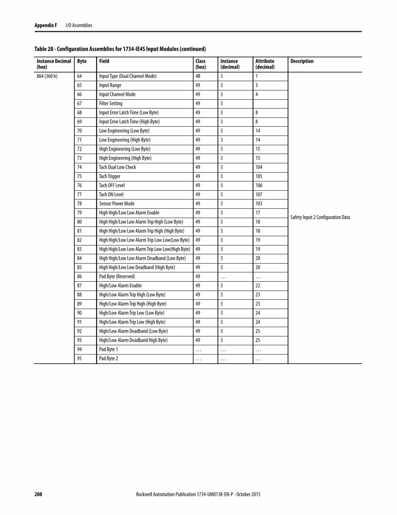
Appendix F I/O Assemblies
864 (360 h) 64 Input Type (Dual Channel Mode) 4B 3 1
Safety Input 2 Configuration Data
65 Input Range 49 3 3
66 Input Channel Mode 49 3 4
67 Filter Setting 49 3
68 Input Error Latch Time (Low Byte) 49 3 8
69 Input Error Latch Time (High Byte) 49 3 8
70 Low Engineering (Low Byte) 49 3 14
71 Low Engineering (High Byte) 49 3 14
72 High Engineering (Low Byte) 49 3 15
73 High Engineering (High Byte) 49 3 15
74 Tach Dual Low Check 49 3 104
75 Tach Trigger 49 3 105
76 Tach OFF Level 49 3 106
77 Tach ON Level 49 3 107
78 Sensor Power Mode 49 3 103
79 High High/Low Low Alarm Enable 49 3 17
80 High High/Low Low Alarm Trip High (Low Byte) 49 3 18
81 High High/Low Low Alarm Trip High (High Byte) 49 3 18
82 High High/Low Low Alarm Trip Low Low(Low Byte) 49 3 19
83 High High/Low Low Alarm Trip Low Low(High Byte) 49 3 19
84 High High/Low Low Alarm Deadband (Low Byte) 49 3 20
85 High High/Low Low Deadband (High Byte) 49 3 20
86 Pad Byte (Reserved) 49 … …
87 High/Low Alarm Enable 49 3 22
88 High/Low Alarm Trip High (Low Byte) 49 3 23
89 High/Low Alarm Trip High (High Byte) 49 3 23
90 High/Low Alarm Trip Low (Low Byte) 49 3 24
91 High/Low Alarm Trip Low (High Byte) 49 3 24
92 High/Low Alarm Deadband (Low Byte) 49 3 25
93 High/Low Alarm Deadband High Byte) 49 3 25
94 Pad Byte 1 … … …
95 Pad Byte 2 … … …
Table 28 - Configuration Assemblies for 1734-IE4S Input Modules (continued)
Instance Decimal (hex)
Byte Field Class (hex)
Instance (decimal)
Attribute (decimal)
Description
208 Rockwell Automation Publication 1734-UM013K-EN-P - October 2015
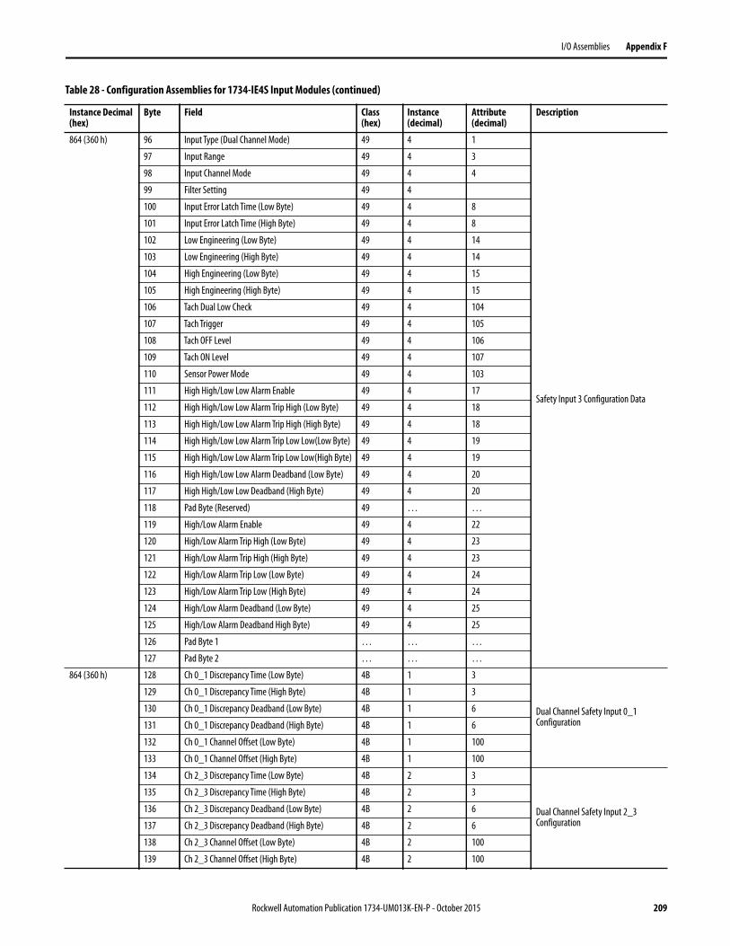
I/O Assemblies Appendix F
864 (360 h) 96 Input Type (Dual Channel Mode) 49 4 1
Safety Input 3 Configuration Data
97 Input Range 49 4 3
98 Input Channel Mode 49 4 4
99 Filter Setting 49 4
100 Input Error Latch Time (Low Byte) 49 4 8
101 Input Error Latch Time (High Byte) 49 4 8
102 Low Engineering (Low Byte) 49 4 14
103 Low Engineering (High Byte) 49 4 14
104 High Engineering (Low Byte) 49 4 15
105 High Engineering (High Byte) 49 4 15
106 Tach Dual Low Check 49 4 104
107 Tach Trigger 49 4 105
108 Tach OFF Level 49 4 106
109 Tach ON Level 49 4 107
110 Sensor Power Mode 49 4 103
111 High High/Low Low Alarm Enable 49 4 17
112 High High/Low Low Alarm Trip High (Low Byte) 49 4 18
113 High High/Low Low Alarm Trip High (High Byte) 49 4 18
114 High High/Low Low Alarm Trip Low Low(Low Byte) 49 4 19
115 High High/Low Low Alarm Trip Low Low(High Byte) 49 4 19
116 High High/Low Low Alarm Deadband (Low Byte) 49 4 20
117 High High/Low Low Deadband (High Byte) 49 4 20
118 Pad Byte (Reserved) 49 … …
119 High/Low Alarm Enable 49 4 22
120 High/Low Alarm Trip High (Low Byte) 49 4 23
121 High/Low Alarm Trip High (High Byte) 49 4 23
122 High/Low Alarm Trip Low (Low Byte) 49 4 24
123 High/Low Alarm Trip Low (High Byte) 49 4 24
124 High/Low Alarm Deadband (Low Byte) 49 4 25
125 High/Low Alarm Deadband High Byte) 49 4 25
126 Pad Byte 1 … … …
127 Pad Byte 2 … … …
864 (360 h) 128 Ch 0_1 Discrepancy Time (Low Byte) 4B 1 3
Dual Channel Safety Input 0_1 Configuration
129 Ch 0_1 Discrepancy Time (High Byte) 4B 1 3
130 Ch 0_1 Discrepancy Deadband (Low Byte) 4B 1 6
131 Ch 0_1 Discrepancy Deadband (High Byte) 4B 1 6
132 Ch 0_1 Channel Offset (Low Byte) 4B 1 100
133 Ch 0_1 Channel Offset (High Byte) 4B 1 100
134 Ch 2_3 Discrepancy Time (Low Byte) 4B 2 3
Dual Channel Safety Input 2_3 Configuration
135 Ch 2_3 Discrepancy Time (High Byte) 4B 2 3
136 Ch 2_3 Discrepancy Deadband (Low Byte) 4B 2 6
137 Ch 2_3 Discrepancy Deadband (High Byte) 4B 2 6
138 Ch 2_3 Channel Offset (Low Byte) 4B 2 100
139 Ch 2_3 Channel Offset (High Byte) 4B 2 100
Table 28 - Configuration Assemblies for 1734-IE4S Input Modules (continued)
Instance Decimal (hex)
Byte Field Class (hex)
Instance (decimal)
Attribute (decimal)
Description
Rockwell Automation Publication 1734-UM013K-EN-P - October 2015 209
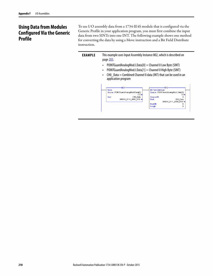
Appendix F I/O Assemblies
Using Data from Modules Configured Via the Generic Profile
To use I/O assembly data from a 1734-IE4S module that is configured via the Generic Profile in your application program, you must first combine the input data from two SINTs into one INT. The following example shows one method for converting the data by using a Move instruction and a Bit Field Distribute instruction.
EXAMPLE This example uses Input Assembly Instance 802, which is described on
page 203.
• POINTGuardAnalogMod.I.Data[0] = Channel 0 Low Byte (SINT)
• POINTGuardAnalogMod.I.Data[1] = Channel 0 High Byte (SINT)
• CH0_Data = Combined Channel 0 data (INT) that can be used in an application program
210 Rockwell Automation Publication 1734-UM013K-EN-P - October 2015

Appendix G
History of Changes
This appendix summarizes the changes that were made in each revision of this manual.
1734-UM013I-EN-P, May 2013
1734-UM013H-EN-P, August 2012
1734-UM013G-EN-P, August 2012
1734-UM013F-EN-P, June 2012
Change
Added introduction to Studio 5000 Environment
Added GuardLogix® 5570 Controller Systems Safety Reference Manual to Additional Resources
Added new diagram for 2-wire Current (4…20 mA) Sensor (SIL1 or SIL2) with Resistor
Added Fault Code Definitions for 1734-IE4S Modules
Updated Safety Data
Change
Updated the specification for Tachometer mode
Change
Updated compliance references
Updated Warning statements concerning compliance
Updated the Ex Certification
Updated the History
Change
Expanded Additional Resources to include terminal assembly and power supply installation instruction publications
Added information on safety analog inputs
Added RSLogix™ 5000 software minimum version requirements
Updated references to controller safety system publications
Added information on safe states of the analog input module
Information on module configuration when using the GuardLogix safety application instructions
Added safety analog input features
Updated the description of the muting lamp test
Added Analog I/O Status Data
New Chapter: Guidelines for Placing Power Supplies and Modules in a System
Identified key positions for 1734-IE4S modules
Rockwell Automation Publication 1734-UM013K-EN-P - October 2015 211

Appendix G History of Changes
1734-UM013E-EN-P, March 2012
Not published.
1734-UM013D-EN-P, September 2011
1734-UM013C-EN-P, August 2010
Updated information on wiring POINT Guard I/O™ modules including 1734-IE4S modules
Illustrated 1734-IE4S field connections
Safety analog-input-module wiring guidelines and examples
List of Rockwell Automation® Bulletin 1606 PELV/SELV- compliant power supplies
Revised power supply considerations and examples
Updated Ethernet adapter configuration procedures
Clarified information on ‘cycle inputs’ condition
Corrected status tags for output modules
Configuring the 1734-IE4S module when used in a GuardLogix system
Configuring the 1734-IE4S module when used in a SmartGuard™ system
New chapter: Configuring Safety Connections between a GuardLogix Controller and POINT Guard I/O Modules on a DeviceNet Network
Information on resetting the module to out-of-box condition is now in the chapter on replacing a module
Revised information on replacing I/O modules in GuardLogix systems
Revised information on replacing I/O modules in SmartGuard systems
Added description of Sensor Power status indicator on 1734-IE4S modules
Information on using a Message instruction to access information on safety analog input faults
Specifications for 1734-IE4S modules
Step response and filter response data for 1734-IE4S
Temperature derating for 1734-IE4S modules
Updated legislation and standards section and moved it to follow certifications
Updated safety data, including PFD/PFH values, MTTF, and STR
List of safety analog input module configuration parameters
Information on the safety analog input module’s I/O and configuration assemblies
Added a history of changes
Change
ChangeUpdated values for maximum power dissipation and maximum thermal dissipation
ChangeMuting lamp operation (test outputs T1 and T3)
Updated surrounding air specification
Revised TÜV certification
212 Rockwell Automation Publication 1734-UM013K-EN-P - October 2015

History of Changes Appendix G
1734-UM013B-EN-P, June 2009
1734-UM013A-EN-P, February 2009
Initial release
ChangeRevised information ISO International Standard
IEC European Standard
Environment and enclosure
Removal and insertion under power
Monitoring a test output status attribute ID
1734-IB8S Input voltage specification
Off-state input voltage specification
1734-IB8S and 1734-OB8S temperature ranges
Isolation voltage specification
North American Temperature Code
Radiated RF Immunity specification
CE certification
TÜV certification
New information European Hazardous Location Approval
Warning statement about European Zone 2 certification
North American Hazardous Location Approval
Setting the node address of a POINT Guard I/O module
Resetting POINT Guard I/O modules to out-of-box condition
Auto-addressing with a 1734-PDN adapter
IEC Temperature Code
c-UL-us certification
Ex certification
ODVA certification
Rockwell Automation Publication 1734-UM013K-EN-P - October 2015 213

Appendix G History of Changes
Notes:
214 Rockwell Automation Publication 1734-UM013K-EN-P - October 2015

Index
Numerics1734-AENT 18
add and configure 77firmware revision 78
1734-AENTR 18
1734-EP24DC 46, 47, 48
1734-EPAC 46
1734-FPD 46, 47
1734-IB8Sfield connections 60muting lamp operation 42
1734-IB8S input assembly 132
1734-IB8S output assembly 132
1734-IE4Sfield connections 61input range 31power supply 58
1734-IE4S input assembly 133
1734-OB8Sfield connections 60
1734-OB8S input assembly 132
1734-OB8S output assembly 132, 133
1734-PDN 18, 108
auto-addressing 1101734-TB 54, 66
1734-TB3 54
1734-TB3S 54
1734-TBS 54
1734-TOP 54, 66
1734-TOP3 54, 66
1734-TOP3S 54
1734-TOPS 54
1756-EN2T/A 76
Aactivate safety input data 30
Active state 85
adapter 77
add safety connection 123
Advanced Connection Reaction Time Limit 104
alarm 33, 99
configuration 99deadband 34, 99over-range 44under-range 44
Alarm tab 99
analog input 19
configuration tab 96configure 93data 103status indicator 161wiring 58, 66-72
architectures 20
auto-addressing 110
Bbroken wire 31
detection 19, 44, 87Bulletin 100S 16
Bulletin 440G 16
Bulletin 440H 16
Bulletin 440K 16
Bulletin 440P 16
Bulletin 700S 16
Bulletin 800F 16
Bulletin 800T 16
Bulletin 802T 16
CCategory 18, 19, 21
certification body 16
channel offset 96
chassis size 79
CIP safety 143
architectures 20protocol 18, 154
Class 2 45
cleaning modules 17
combined input status 44, 124
tag 83tags 102
combined output status 44, 124
tags 102common terms 11
communicationconnections 44
compatible module 77, 78, 81, 90, 95
conductors 59
configurationassemblies 204download 106, 127ownership 105, 146safety 113save 106, 127settings 197verify 137-142
configuration lockstatus indicator 160
configuration signature 105
comparison 142copy 134mismatch 138
configurealways 153
connection 11
example 144lost 44removable terminal block 57safety input 104
connection faultedtags 102, 103, 105
connection reaction time limit 125
Rockwell Automation Publication 1734-UM013K-EN-P - October 2015 215

contactors 16
controller I/O data 27
controlling devices 16
copyconfiguration signature 134safety network number 135
crossed cable example 144
current input range 31
cycle inputs 85
DDC voltages 59
DCAsee Dual-channel Analog safety instruction
DCAFsee Dual-channel Analog safety instruction
deadband 34, 96
alarm 99tolerance 35
delay time 86
derating1734-IB8S 1701734-IE4S 1861734-OB8S 171
device statusSafety Device Verification Wizard 138verification 139
DeviceNet safetyarchitecture 21conformance test 187
devices, safety 18
diagnostic data 44
digital input 18
modules 79status indicator 161
digital output 3, 19
status indicator 162DIN rail 59
disable keying 77, 78
discharge, electrostatic 54
discrepancy fault 96, 118
discrepancy time 18, 19, 27, 28, 29, 85, 96
door interlocking switch 16
door monitoring switch 62
download configuration 106, 127
download DeviceNet configuration 136-142
dual low inputs detection 100
dual-channel 92
complementary 27, 29, 85complimentary 23discrepancy error 44discrepancy fault 35equivalent 23, 24, 27, 28, 31, 35, 85, 96, 97,
118mode 18, 19, 27, 40, 41safety contactors 65wiring 63, 65
Dual-channel Analog safety instruction 96, 98
EEDS
See electronic data sheetelectronic data sheet 11, 108
electronic keying 90, 95
electrostatic discharge 54
emergency stop switch 16, 62, 104
wiring 63EN
60079-0 5260079-15 52
enclosure 53
environment 53
equivalent 28
E-stopSee emergency stop switch
EtherNet/IPsafety architecture 20
Ethernet/IPmodule 76
exact match 77, 78, 81, 90, 95
exampleconnections not made 144crossed cable 144
explicit messaging 83, 87
external means 81, 90, 95
Ffalling edge 101
faultdetection 26, 28, 40, 41monitoring 18reason 103, 165recovery 30, 41
fault detection 29
fieldconnection 60power 46
field power distributor 46, 47
filter 98
firmware 16
functional verification test 21
Ggate monitoring switch
wiring 63generic DeviceNet safety module profile 129,
130
glossary 11
grounding 59
GuardLogix controller 129
SNN 145Guardmaster product 16
216 Rockwell Automation Publication 1734-UM013K-EN-P - October 2015

Hhazardous location 52, 53
High alarm 33, 44, 99
status 103High Engineering value 31, 98
High High alarm 33, 44, 99
status 103hold last state 87
II/O
assemblies 201replacement 153status data 18
icondevice status 138
IEC60204-1 18761131-2 18761508 15, 18762061 187
inputassemblies 201signal lines 25
input assembly1734-IB8S 1321734-IE4S 1331734-OB8S 132
input configuration tab 84
input data 82, 102
input delay time 86
input delaysSee on-delay and off-delay
input error latch time 87, 97
input filter 98
input power error bit 102
input statusanalog 44combined 44point 44tags 83
installI/O modules 56mounting base 54removable terminal block 57
ISO 13849-1 15, 187
Kkeyswitches 56
Llegislations and standards 187
light curtain 62
limit switches 16
listen only 79
lockSee safety-lock
Logix Designer application 75
reset module 146lost connection 44
Low alarm 33, 44, 99
status 103Low Engineering value 31, 98
Low Low alarm 33, 44, 99
status 103Low Voltage Directive 45
LVD 45
Mmasters 11
mean time between failure 189
message instructions 163
configure 164mismatch
configuration signature 138missing device
icon 138module
guidelines 11, 15precautions 17status indicator 160
mounting 54-58
mounting baseassembly 54connect the module 56install 54installation 54remove 58uninstall 58
MS status indicator 106, 127
muting lamp 19, 42, 87
status 102muting status 124
tag 83
Nnetwork adapters 18
network delay multiplier 105
network status indicatorSee NS status indicator
node address 108
node conditioning tool 109
NPN-style sensors 36, 66
NS status indicator 106, 127, 150, 152, 156, 160
OODVA 11, 187
off-delay 18, 30, 86
off-level 37
on-delay 18, 30, 86
on-level 37
Rockwell Automation Publication 1734-UM013K-EN-P - October 2015 217
online button 136
out-of-box 149
reset module 145output
assemblies 202monitor 44safe state 23signals 19
output assembly1734-IB8S 1321734-OB8S 132, 133
Output Configuration tab 92
output data 102
menu 82tag 102tags 82
Output Error Latch Time 93
output power error bit 102
output readbacktags 102
output statuscombined 44monitor 44point 44test outputs 44
overfrequency bit 38
ownership 105, 127
Ppacket size 124, 125
parameterssafety configuration 115, 118
PELV 45
Performance Level 18, 19
PFD 11, 21
See probability of failure on demand.PFH 11, 21
See probability of failure per hour.PL 21
PLC controllers 20
PNP-style sensors 36, 66
point input status 44, 102, 124
Point modedigital input 86test output 87
point operation type 85
point output status 44
tags 102POINTBus
backplane 45, 46Pollution Degree 2 53
powerfield 46status 124status indicator 161
power supply 45, 46
examples 47-48external 58, 72sensor outputs 72
probability of failureon demand 11, 189per hour 11, 189
process alarms 33
configuration 99tags 103
proof test 11
protected extra-low voltage 45
publications, related 13
pulse count 101
pulse period 25, 39
pulse test 19, 86, 92
output specifications 169, 181pulse testing 86
pulse width 25, 39
push button 61
Rrack optimization 79
readback 103
tags 102ready to be safety locked 141
ready to be verified 139
redundant control 19
related publications 13
relays with focibly-guided contacts 16
removable terminal block 54, 57
connect 57remove
mounting base 58replace
configure always enabled 153configure only… enabled 148modules 17, 155
requested packet interval 104
resetmodule 145ownership 146
resistors 66
response time 39
rising edge 101
risk assessment 16
RPI 104
RSLinx software 108, 112
RSLogix 5000 softwareversion 20
RSNetWorx for DeviceNet software 15, 107, 112, 143
reset module 147version 20
RSWho 112
RTB 57
See removable terminal blockrun mode
tag 102, 103
218 Rockwell Automation Publication 1734-UM013K-EN-P - October 2015

Ssafe state 23, 24
safetyadministrator 11, 17analog input 19analog inputs 31application requirements 21configuration 113configuration tab 113, 117devices 18digital input data 26digital input modules 79digital inputs 18, 24digital outputs 3, 19, 39, 41extra-low voltage 45input connection 104input data 30input fault recovery 30input status 26inputs 124monitor 124output modules 88output specifications 171, 184output with test pulse 39outputs 17, 23, 124sensors 16system architecture 20tab 104
safety connection tab 122
safety contactorwiring 64, 65
Safety Device Verification Wizarddefinition 137device status 138reports 141run 137safety-lockselect devices 139summary 142upload and compare 140Welcome page 137
safety extra-low voltage 45
safety instruction 96, 98
safety network number 11, 21, 81, 89, 94, 105, 143, 144
copy 135error icon 138mismatch 155setting 144-145
safety signature 21, 144
safety task watchdog 93, 97
safety-lockdevicesicon 138
save 106, 127
scalinganalog inputs 31
schematic diagrams 61
SELV 45
sensor poweroutputs 58over-range 44status indicator 161under-range 44
sensorsNPN-style 36PNP-style 36power supply 72, 98wiring 66
sequential auto-addressing 110
short-circuitbetween input signal lines 25detection 18
short-circuit detection 19
SIL 21
single-channel 23, 24, 85, 92, 96, 118
discrepancy error 44mode 18, 19, 26, 31safety contactor 64wiring 64
slaves 11
SLogix 5000 softwareversion 20
SmartGuard controllerSNN 145
SNN 11, 21
See safety network numberSee safety network number.
standard 11
output data 102outputs 19
standardslegislations 187
states of tags 102
status bitsinput power error 102muting 42, 43output power error 102
status data 43, 102, 103
input and controller 27status indicators 17, 106, 159
analog inputs 161configuration 160module 160network 160safety input 161safety output 162sensor power 161
stuck high faults 41
Studio 5000 environment 11
version 20suitability for use 16
switchdoor interlocking 16door monitoring 62emergency stop 104gate monitoring 63limit 16
system reaction time 21
Rockwell Automation Publication 1734-UM013K-EN-P - October 2015 219

Ttachometer
dual low inputs detection 44, 100, 103frequency 36frequency over-range 44frequency under-range 44input wiring 58mode 31, 36, 100off-level 37, 101on-level 37, 101overfrequency 103reset 103status indicator 161under-frequency 103wiring 66
tags 102
combined input status 83input data 82input status 83muting status 83output data 82, 90output status 91status and alarms 95status, alarms, fault 95values 102, 103
terminology 11
Test Output Fault Action parameter 87
test outputs 17, 18, 19, 24, 42, 43, 82, 83, 86
clear off 87configure 87hold last state 87status 44, 124status tags 102tab 87
test pulse 25, 39
test source 86
this controller 81, 90, 95
timeout multiplier 105
UUL 45
uninstallmounting base 58
unknown deviceicon 138
upload and compareSafety Device Verification Wizard 140
USB 107, 108
Vverification reports
failure report 141Safety Device Verification Wizard 141
verifyDeviceNet Safety configuration 137-142FAILED 141select devices 139
verify failed 139
verify not supported 139
voltage input range 31
Wwarning
configuration 99welcome page 137
wiringanalog inputs 66-72conductors 59dual-channel devices 63emergency stop switch 63examples 63-72gate monitoring switch 63modules 58-72redundant safety contactor 65safety contactor 64sensors 66single-channel 64tachometer inputs 66
220 Rockwell Automation Publication 1734-UM013K-EN-P - October 2015


Publication 1734-UM013K-EN-P - October 2015Supersedes Publication 1734-UM013J-EN-P - March 2013 Copyright © 2015 Rockwell Automation, Inc. All rights reserved. Printed in the U.S.A.
Rockwell Automation Support
Rockwell Automation provides technical information on the Web to assist you in using its products.At http://www.rockwellautomation.com/support you can find technical and application notes, sample code, and links to software service packs. You can also visit our Support Center at https://rockwellautomation.custhelp.com/ for software updates, support chats and forums, technical information, FAQs, and to sign up for product notification updates.
In addition, we offer multiple support programs for installation, configuration, and troubleshooting. For more information, contact your local distributor or Rockwell Automation representative, or visithttp://www.rockwellautomation.com/services/online-phone.
Installation Assistance
If you experience a problem within the first 24 hours of installation, review the information that is contained in this manual. You can contact Customer Support for initial help in getting your product up and running.
New Product Satisfaction Return
Rockwell Automation tests all of its products to help ensure that they are fully operational when shipped from the manufacturing facility. However, if your product is not functioning and needs to be returned, follow these procedures.
Documentation Feedback
Your comments will help us serve your documentation needs better. If you have any suggestions on how to improve this document, complete this form, publication RA-DU002, available at http://www.rockwellautomation.com/literature/.
United States or Canada 1.440.646.3434
Outside United States or Canada Use the Worldwide Locator at http://www.rockwellautomation.com/rockwellautomation/support/overview.page, or contact your local Rockwell Automation representative.
United States Contact your distributor. You must provide a Customer Support case number (call the phone number above to obtain one) to your distributor to complete the return process.
Outside United States Please contact your local Rockwell Automation representative for the return procedure.
Rockwell Otomasyon Ticaret A.Ş., Kar Plaza İş Merkezi E Blok Kat:6 34752 İçerenköy, İstanbul, Tel: +90 (216) 5698400
Rockwell Automation maintains current product environmental information on its website at
http://www.rockwellautomation.com/rockwellautomation/about-us/sustainability-ethics/product-environmental-compliance.page.