Pocket Size Digital Multimeter Models: 72-8150 and 72-8155 · Models: 72-8150 and 72-8155 Pocket...
12
1 Models: 72-8150 and 72-8155 Pocket Size Digital Multimeter
Transcript of Pocket Size Digital Multimeter Models: 72-8150 and 72-8155 · Models: 72-8150 and 72-8155 Pocket...
1
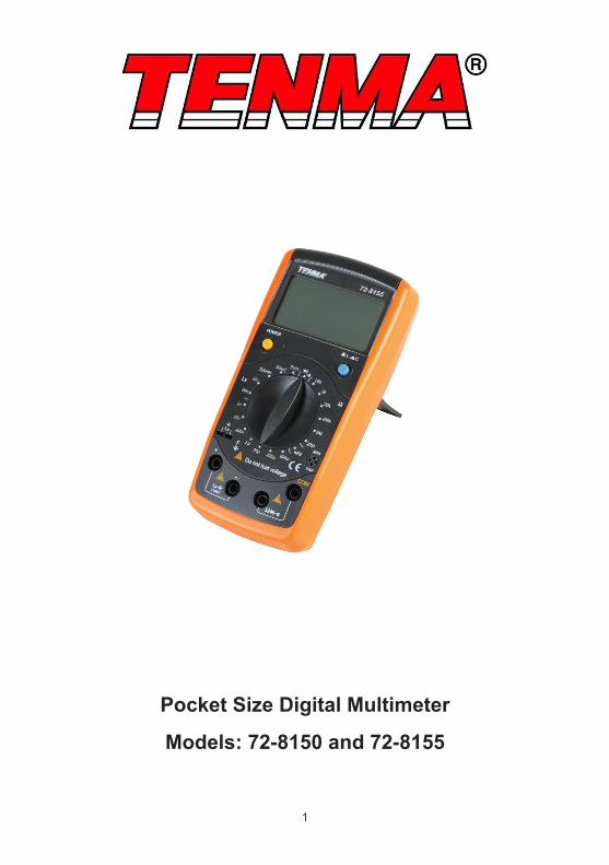
Models: 72-8150 and 72-8155
Pocket Size Digital Multimeter
2
Please read these instructions carefully before use and retain for future reference.• Please operate according to this manual, otherwise the protection provided by the
device will be impaired or fail.• Check the test leads, probe and case insulation condition before using. If you find
any breakage, damage or abnormality, or you consider the device is broken, stop using the device immediately.
• When using the test probes, keep your fingers behind the finger protection rings. • Ensure all inputs are less than the range selected otherwise it may cause electrical
shock or meter damage.• Do not apply voltage to the meter.• Disconnect circuit power and discharge all high-voltage capacitors before testing
resistance, continuity, capacitance or diodes.• Do not use the meter with the back cover removed.• Do not adjust the range selector during measurement.• Replace the batteries as soon as the low battery indicator appears on the display.• Remove dead batteries from the meter or if it is not going to be used for a long
time.• Never mix old and new batteries together, or different types of batteries.• Never dispose of batteries in a fire, or attempt to recharge ordinary batteries.• Before replacing the battery, turn off the meter and disconnect all the test probes.• To prolong battery life turn off the meter after use..
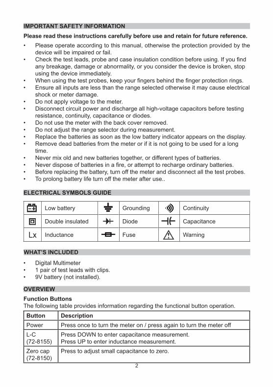
ELECTRICAL SYMBOLS GUIDE
WHAT’S INCLUDED
• Digital Multimeter• 1 pair of test leads with clips.• 9V battery (not installed).
IMPORTANT SAFETY INFORMATION
OVERVIEW
Low battery Grounding Continuity
Double insulated Diode Capacitance
Lx Inductance Fuse Warning
Function ButtonsThe following table provides information regarding the functional button operation.
Button DescriptionPower Press once to turn the meter on / press again to turn the meter offL-C (72-8155)
Press DOWN to enter capacitance measurement. Press UP to enter inductance measurement.
Zero cap (72-8150)
Press to adjust small capacitance to zero.

3
RANGE SELECTOR FUNCTIONS AND DISPLAY
ΩΩΩ
1
2
3
45
6
7
No Symbol Meaning1 Data hold is active.2 The battery is low.3 ß Transistor test.
4 Diode test.5 The continuity buzzer is on.6
pFnFμFmF
Measurement of unit of capacitance.Picofarad. 1 x 10-12 or 0.000000000001farads.Nanofarad. 1 x 10⁻⁹ or 0.000000001farads.Microfarad.1 x 10-6 or 0.000001 farads.Millifarad. 1 x 10⁻³ or 0.001 farads.
7
k M
Measurement of unit of resistance.Ohm.kiloohm. 1 x 10³ or 1000 ohms.Megaohm. 1 x 10⁶ or 1,000,000 ohms.
8H
mH
Measurement of unit of inductance.Henry.mH. Millihenry 1 x 10⁻³ or 0.001 henry.
H
1. LCD display
2. L-C switch / zero capacitance adjustment switch
3. Transistor jack.
4. Resistance, diode and continuiyty terminal.
5. Capacitance and inductance terminal.
6. Range selector.
7. Power.

4
Measuring Continuity.
• To test for continuity, do the following:1. Insert the red test clip into the Ω terminal and the black test clip into the
COM terminal.2. Set the range selector to .• Connect the test clips across with the
object being measured.• The beeper sounds continuously when
the resistance value of the tested circuit ≤10Ω .
• The beeper may not sound when the resistance value of the test circuit >100Ω.
• The meter displays the value of the test resistance.
OPERATION
Measuring Resistance.
• To measure voltage, do the following:1. Insert the red test clip into the Ω terminal and the black test clip into COM
terminal.2. Set the range selector to Ω.• The resistance ranges are 20Ω, 200Ω, 2kΩ,
20kΩ, 200kΩ, 2MΩ, 20MΩ and 2000MΩ.• Connect the test clips across the object
being measured.• The measured value shows on the display.Note: When measuring at 20Ω and 200Ω range, the test clips can add 0.1 to 0.3Ω error to resistance. To obtain precise readings in these low-resistance measurement, short circuit the input terminals beforehand and record the reading obtained and subtract this from the measured reading displayed.• The meter displays “1” when there is no input, for example, open circuit situation.• For high resistance measurement (>1MΩ), it is normal to take several seconds to
obtain a stable reading.• When resistance measurement has been completed, disconnect the connection
between the test clips and the circuit under test and remove the test clips from the input terminals of the meter.

5
Measuring Diode.
Use the diode test to check diodes, transistors, and other semiconductor devices. The diode test sends a current through the semiconductor junction, and then measures the voltage drop across the junction. Note: A good silicon junction drops between 500mV and 800mV.• To test a diode out of a circuit, do the following:1. Insert the red test clip into the
Ω terminal and the black test clip into the COM terminal.
2. Set the range selector to .• For forward voltage drop readings on
any semiconductor component, place the red test clip on the component’s anode and place the black test clip on the component’s cathode.
• The display shows the diode forward voltage drop’s nearest value.
• When diode test has been completed, disconnect the connection between the test clips and the circuit under test and remove the test clips from the input terminals of the meter.
Transistor testing.
• To test transistors, do the following:1. Set the rotary switch to hFE measurement mode.
Check if the transistor is PNP or NPN type2. Insert the transistor to be measured to the
corresponding Transistor Jack.• The display shows the transistors nearest value.• When transistor measurement has been
completed, disconnect the connection between the test clips and the circuit under test and remove the test clips from the input terminals of the meter.

6
Measuring Capacitance.
• To measure capacitance, do the following:1. Insert the red test clip into the CAP+
terminal and the black test clip into the CAP- terminal. For small value capacitor measurement, insert the capacitor into the small value jack.
2. Set the range selector to F. If the value of capacitor to be measured is unknown, use the maximum measurement position 600μF and decrease the range step by step until a satisfactory reading is obtained and the overload icon “1” is not showing.
• When testing polarized capacitors, use the red test clip on the capacitor’s positive lead, and the black test clip on the capacitor’s negative lead. With non-polarized capacitors, either direction is acceptable.
• When measuring small value capacitor, that is 200pF, 2nF and 20nF, first open circuit the test clips or the Small Value Capacitance Jack, then turn the Capacitance Zero Adjustment Switch to adjust zero (72-8150 model).
• The meter displays the measured value.• When capacitance measurement has been completed, disconnect the connection
between the test clips and the item under test and remove the test clips from the input terminals of the meter
• To minimize the effect of capacitance stored in the test clips, the test clips should be as short as possible.
Note: The meter cannot check the quality of the capacitor.
• Stable and solid connections are essential when measuring large capacitors.• When the tested capacitor is leaking or damaged and the tested value is
not stable, the capacitor may have problems. You need to use other tools or equipment to check and confirm.

7
Measuring Inductance (72-8155 only) • To measure inductance, do the
following:1. Set the rotary switch to Lx
measurement mode. If the tested inductance value is unknown, use the maximum measurement position and decrease the range step by step until a satisfactory reading is obtained.
2. Insert the test clips into the corresponding Lx input terminals.
• The measured value shows on the display.
• When measuring inductors in the 2mH range, you should first short circuit the test leads and note the measured inductance value of the leads. Then the correct reading is the measured reading, minus the short circuit value.
• The small value jack on the surface of the meter should be used when measuring small value inductors.
Note: The meter cannot check the quality of the inductance.
• When inductance measurement has been completed, disconnect the connection between the test clips and the circuit under test and remove the test clips from the input terminals of the meter.
BATTERY AND FUSE REPLACEMENT
• If icon appears on LCD, please replace the battery as follows:
1. Disconnect test probes from circuits being measured, turn range selector to OFF position.
2. Remove the screw from the battery cover, and separate the battery cover from the rear casing.
3. Replace the 9V alkaline battery with a new one (NEDA1604 or 0062 or 6F22 or 006P) noting the correct polarity.
4. Refit the battery cover and tighten the screw. Battery
Screw

8
Replacing the Fuses.
Warning: To avoid electrical shock, personal injury or damage to the meter, use specified fuses ONLY in accordance with the following procedure.
1. Turn the meter power off and remove all connections from the terminals.
2. Remove the screw from the battery compartment, and separate the battery compartment from the case bottom.
3. Remove the screws from the case bottom, and separate the case top from the case bottom.
4. Remove the fuse by gently prying one end loose, then take out the fuse from its holder.
5. Install ONLY replacement fuses with the identical type and specification as follows and make sure the fuse is fixed firmly in it’s holder. Fuse 1: 0.315A, 250V, fast type fuse, 5x20 mm.
6. Replace the battery compartment and the case top, and reinstall the screw.7. Replace the case bottom and case top, and reinstall the screws.
Note: Fuse replacement is seldom required. Blown fuses are typically a result of improper use.
Screw

9
SPECIFICATIONS
Maximum Display 1999.Measurement Speed Updates 2-3 times /second.Polarity Auto. (Display “-“ when negative)Overload Indication Display “1”Range Manual RangingCapacitance zero adjustment around ±20pFTemperature:OperatingStorage
0oC~40oC (32oF ~104oF).-10oC~50oC (14oF~122oF).
Relative Humidity 75% @ 0oC - 30oC;50% @ 31 - 40oC.
Altitude Operating: 2,000 m.Storage 10,000 m.Battery Type One piece of 9V Alkaline
(NEDA1604 or 0062 or 6F22 or 006P).
Low Battery Display
Dimensions 6.77” (H) x 3.27” (W) x 1.50”(D).Weight Approximate 310g (including battery).Safety/Compliances EMC EN61326.
10
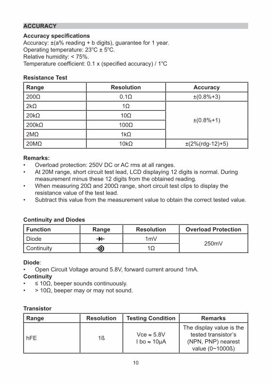
Accuracy specifications Accuracy: ±(a% reading + b digits), guarantee for 1 year.Operating temperature: 23oC ± 5oC.Relative humidity: < 75%.Temperature coefficient: 0.1 x (specified accuracy) / 1oC
Resistance TestRange Resolution Accuracy200Ω 0.1Ω ±(0.8%+3)2kΩ 1Ω
±(0.8%+1)20kΩ 10Ω200kΩ 100Ω2MΩ 1kΩ20MΩ 10kΩ ±(2%(rdg-12)+5)
Remarks:• Overload protection: 250V DC or AC rms at all ranges.• At 20M range, short circuit test lead, LCD displaying 12 digits is normal. During
measurement minus these 12 digits from the obtained reading.• When measuring 20Ω and 200Ω range, short circuit test clips to display the
resistance value of the test lead.• Subtract this value from the measurement value to obtain the correct tested value.
ACCURACY
Continuity and DiodesFunction Range Resolution Overload ProtectionDiode 1mV
250mVContinuity 1Ω
Diode:• Open Circuit Voltage around 5.8V, forward current around 1mA.Continuity• ≤ 10Ω, beeper sounds continuously.• > 10Ω, beeper may or may not sound.
TransistorRange Resolution Testing Condition Remarks
hFE 1ß Vce ≈ 5.8VI bo ≈ 10μA
The display value is thetested transistor’s
(NPN, PNP) nearestvalue (0~1000ß)
11
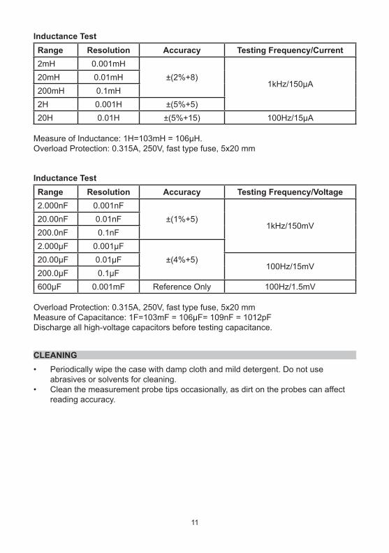
Inductance TestRange Resolution Accuracy Testing Frequency/Current2mH 0.001mH
±(2%+8)1kHz/150µA
20mH 0.01mH200mH 0.1mH2H 0.001H ±(5%+5)20H 0.01H ±(5%+15) 100Hz/15µA
Measure of Inductance: 1H=103mH = 106μH.Overload Protection: 0.315A, 250V, fast type fuse, 5x20 mm
Inductance TestRange Resolution Accuracy Testing Frequency/Voltage2.000nF 0.001nF
±(1%+5)1kHz/150mV
20.00nF 0.01nF200.0nF 0.1nF2.000µF 0.001µF
±(4%+5)20.00µF 0.01µF100Hz/15mV
200.0µF 0.1µF600µF 0.001mF Reference Only 100Hz/1.5mV
Overload Protection: 0.315A, 250V, fast type fuse, 5x20 mmMeasure of Capacitance: 1F=103mF = 106μF= 109nF = 1012pFDischarge all high-voltage capacitors before testing capacitance.
CLEANING• Periodically wipe the case with damp cloth and mild detergent. Do not use
abrasives or solvents for cleaning.• Clean the measurement probe tips occasionally, as dirt on the probes can affect
reading accuracy.

12
INFORMATION ON WASTE DISPOSAL FOR CONSUMERS OF ELECTRICAL & ELECTRONIC EQUIPMENTThese symbols indicate that separate collection of Waste Electrical and Electronic Equipment (WEEE) or waste batteries is required. Do not dispose of these items with general household waste. Separate for the treatment, recovery and recycling of the materials used. Waste batteries can be returned to any waste battery recycling point which are provided by most battery retailers. Contact your local authority for details of the battery and WEEE recycling schemes available in your area.
Made in China. PR2 9PPMan Rev 1.0