Pocket Guidefor Road Construction and Maintenance
64
Part 1: Inspector’s Job Guide for Highway and Street Construction Part 2: Road and Highway Maintenance Tables Part 3: Asphalt Paving Inspection Check List Part 4: Chip Seal Application Check List Part 5: Concrete Paving Check List Page 63: Bureau Contact Information PUB 372 (10-13) penndot > municipal services Pocket Guide for Road Construction and Maintenance www.dot.state.pa.us
Transcript of Pocket Guidefor Road Construction and Maintenance

Part 1:Inspector’s Job Guide for Highway and Street Construction
Part 2:Road and Highway Maintenance Tables
Part 3:Asphalt Paving Inspection Check List
Part 4:Chip Seal Application Check List
Part 5:Concrete Paving Check List
Page 63:Bureau Contact Information
PUB 372 (10-13)
penndot > municipal services
Pocket Guide for Road Construction and Maintenance
www.dot.state.pa.us

- 1 -
PART 1Inspector’s Job Guidefor Highway & Street
ConstructionPage
Duties Before Beginning Inspection . . . . . . . . . . . . 2
Safety . . . . . . . . . . . . . . . . . . . . . . . . . . . . . . . . . . . 2
Uniform Color Code . . . . . . . . . . . . . . . . . . . . . . . . 2
Wind Chill Equivalent Temperatures . . . . . . . . . . . 3
Plant Mix Bituminous Paving . . . . . . . . . . . . . . . . . 4
Aggregate Course and Truck Scale . . . . . . . . . . . . 5
Culvert Pipe Installation . . . . . . . . . . . . . . . . . . . . . 6
Storm Sewer Installation . . . . . . . . . . . . . . . . . . . . 7
Grading. . . . . . . . . . . . . . . . . . . . . . . . . . . . . . . . . . 8
Seeding, Finishing, Etc. . . . . . . . . . . . . . . . . . . . . . 9
Structures . . . . . . . . . . . . . . . . . . . . . . . . . . . . . . . 10
Geotextiles . . . . . . . . . . . . . . . . . . . . . . . . . . . . . . 13
Bituminous Surface Treatment . . . . . . . . . . . . . . . 14
IntroductionThese guides are intended to cover the very basicduties of inspection by reference to key activities.The guides must be supplemented by reference tocontract documents specifications, special provi-sions, instructional manuals, and guidance by theproject engineer.
uuu

Duties Before BeginningInspection
PA One Call, 1-800-242-1776, www. paonecall.org1. Review plans, special provisions, Construction
and Materials Manual, and specifications thatapply to your assigned duties. Are all requiredpermits obtained and copies onsite? PA Onecall notified? E&S controls in place?
2. Discuss your responsibility and authority withthe project engineer who has day-to-day projectresponsibility.
3. Review the format and required content of yourinspection diary.
4. Review required testing procedure and forms.Read the QC documents.
5. Discuss notification, changes, corrections,delays, rejections, tolerances, and checks withthe project engineer.
6. Ask Questions! If you are not 100% sure ofyour duties, go over them again with the projectengineer.
SafetyReview all operating procedures to assure that activ-ities are performed in the safest manner. Safety iseveryone’s responsibility! When performing dutiesin the presence of traffic, review necessary trafficcontrol requirements.
Uniform Color Code(For Underground Utility Markings)American Public Works Association
White: Proposed Excavation.
Pink: Temporary Survey Markings.
Red: Electric Power Lines, Cables, Conduit andLighting Cables.
Yellow: Gas, Oil, Steam, Petroleum or GaseousMaterials.
Orange: Communication, Alarm or Signal Lines, Cableor Conduit.
Blue: Potable Water.
Purple: Reclaimed Water, Irrigation and Slurry Lines.
Green: Sewers and Drain Lines.
- 2 -
- 3 -
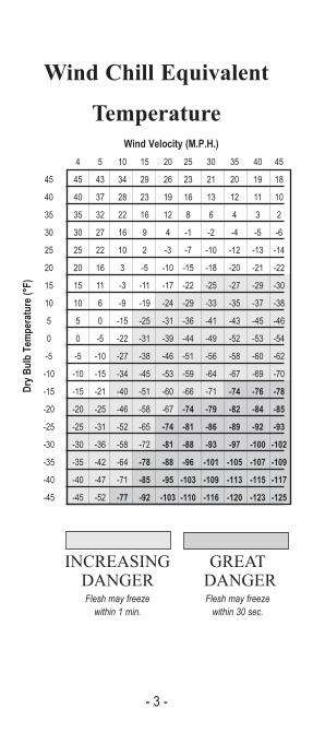
Wind Chill Equivalent
TemperatureWind Velocity (M.P.H.)
4 5 10 15 20 25 30 35 40 45
45 45 43 34 29 26 23 21 20 19 18
40 40 37 28 23 19 16 13 12 11 10
35 35 32 22 16 12 8 6 4 3 2
30 30 27 16 9 4 -1 -2 -4 -5 -6
25 25 22 10 2 -3 -7 -10 -12 -13 -14
20 20 16 3 -5 -10 -15 -18 -20 -21 -22
15 15 11 -3 -11 -17 -22 -25 -27 -29 -30
10 10 6 -9 -19 -24 -29 -33 -35 -37 -38
5 5 0 -15 -25 -31 -36 -41 -43 -45 -46
0 0 -5 -22 -31 -39 -44 -49 -52 -53 -54
-5 -5 -10 -27 -38 -46 -51 -56 -58 -60 -62
-10 -10 -15 -34 -45 -53 -59 -64 -67 -69 -70
-15 -15 -21 -40 -51 -60 -66 -71 -74 -76 -78
-20 -20 -25 -46 -58 -67 -74 -79 -82 -84 -85
-25 -25 -31 -52 -65 -74 -81 -86 -89 -92 -93
-30 -30 -36 -58 -72 -81 -88 -93 -97 -100 -102
-35 -35 -42 -64 -78 -88 -96 -101 -105 -107 -109
-40 -40 -47 -71 -85 -95 -103 -109 -113 -115 -117
-45 -45 -52 -77 -92 -103 -110 -116 -120 -123 -125
INCREASING GREATDANGER DANGERFlesh may freeze Flesh may freeze within 1 min. within 30 sec.
Dry Bulb Temperature (°F)

- 4 -
Plant Mix Bituminous Paving1. Check equipment for specification compliance, and
discuss paving and rolling sequence with contractor.Review all QC documents. Is a Pre-Pave meetingrequired?
2. Check that the surface is smooth, firmly compacted and atcorrect cross section, grade, and alignment. Existingbituminous and concrete bases are to be clean and free ofloose material, and tacked. Excessive joint and cracksealing material should be removed. Pre-level all unevensurfaces.
3. Ensure that truck boxes are clean to prevent build-up (donot use kerosene, diesel fuel or fuel oil). Loads must becovered.
4. Check temperature frequently and be aware of theacceptable temperature range of mix.
5. Insure that scale inspector verifies and initials eachdelivery ticket, unless automated printer is used.
6. Check that paving inspector collects, checks, and initialseach delivery ticket.
7. Observe loads for proper size and shape. Materialsshould have consistent color, complete aggregate coating,and a minimum of segregation.
8. Check that paver maintains a speed which will minimizestop and start operations.
9. Check that paver maintains correct line, grade and crossslope, and has the automatic controls adjusted tominimize screed “bounce” or “drift.”
10. Check mat width, thickness, and yield.
11. Check that construction joints are tight and flush withadjacent surfaces.
12. Insure that mat has a uniform appearance and is free oflongitudinal seams.
13. Check that rolling is as continuous as possible and atproper speed with drive wheel nearest paver. Discussrolling pattern with project engineer, paving foreman ortechnician.
14. Cease vibratory rolling when checking or cracking occurs,or at a specified minimum temperature.
15. Finish rolling to remove all marks and bumps.
16. Monitor density tests to ensure adequate compaction.
17. Check surface with a rolling straightedge for ride quality.
18. Daily records include: workers, hours, equipment, lengthspaved, course, depth, width, tonnage, yield, weather,temperatures, and problems encountered.

- 5 -
Aggregate Courseand Truck Scale
1. Prior to placing base, verify that grade is true tocorrect cross-section and alignment. Check thatsubgrade or subbase is free of ruts, large stones,and excess dust.
2. Observe loads for proper size and makeup.3. Generally, begin placement near the source of sup-
ply. Lifts should not exceed 8” of thickness unlessotherwise approved by the engineer.
4. Check depth and yield (tons per linear feet) toassure uniform coverage.
5. Monitor base preparation needs: mixing by graderto eliminate segregation and hauling ruts, water tocontrol dust and aid in obtaining compaction, androlling to obtain density.
6. Obtain compaction of each lift before placing thenext lift.
7. Collect, check, and initial the weigh ticket for eachload as it arrives at the site.
8. Daily records include: workers, hours, equipment,location, lift thickness, quantity, and yield.

- 6 -
Culvert Pipe Installation1. Review plans and specifications for culvert
installation. PA One call complete?
2. Verify size, type, and length of pipe versus certi-fication numbers.
3. Check pipe for approval stamp and inspect forany subsequent damage or defects.
4. Review control stakes and adjacent terrain forproper drainage.
5. Check trench for proper width and shoringneeds, follow OSHA safety requirements.
6. Check bed for proper grade and compaction.Check shape of bed with template.
7. Place tongue end of concrete pipe in direction offlow and lap in metal pipe so that flow is overlap.
8. Check that concrete pipe joints are snug and liftholes plugged. Banding for corrugated metalpipe shall be installed in accordance with speci-fications.
9. Determine pay length while installing pipe bymultiplying the number of sections by their nom-inal length.
10. Ensure that backfill material is free of large rocksand debris.
11. Check that backfill is placed in accordance withspecifications or as directed by engineer.
12. When complete, verify that pipe is in properalignment and undamaged.
13. Daily records include: trenching, placement andbackfilling information, item, pay length, loca-tion, heat numbers, crew, equipment, and prob-lems encountered.
- 7 -
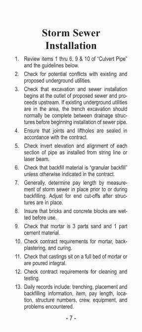
Storm SewerInstallation
1. Review items 1 thru 6, 9 & 10 of “Culvert Pipe”and the guidelines below.
2. Check for potential conflicts with existing andproposed underground utilities.
3. Check that excavation and sewer installationbegins at the outlet of proposed sewer and pro-ceeds upstream. If existing underground utilitiesare in the area, the trench excavation shouldnormally be complete between drainage struc-tures before beginning installation of sewer pipe.
4. Ensure that joints and liftholes are sealed inaccordance with the contract.
5. Check invert elevation and alignment of eachsection of pipe as installed from string line orlaser beam.
6. Check that backfill material is “granular backfill”unless otherwise indicated in the contract.
7. Generally, determine pay length by measure-ment of storm sewer in place prior to or duringbackfilling. Adjust for end cut-offs after struc-tures are in place.
8. Insure that bricks and concrete blocks are wet-ted before use.
9. Check that mortar is 3 parts sand and 1 partcement material.
10. Check contract requirements for mortar, back-plastering, and curing.
11. Check that castings sit on a full bed of mortar orare poured integral.
12. Check contract requirements for cleaning andtesting.
13. Daily records include: trenching, placement andbackfilling information, item, pay length, loca-tion, structure numbers, crew, equipment, andproblems encountered.

- 8 -
Grading1. Review grading and erosion and control plans.2. Inspect clearing and grubbing limits, and measure
quantities. Check contract for disposal of firewoodand debris.
3. Monitor salvaging of topsoil to ensure properdrainage and erosion control.
4. Insure unstable material below subgrade is undercutand measured for final pay. Check with project engi-neer to establish the need for undercut.
5. Ensure that all rock at subgrade elevation is under-cut 6“.
6. Check that masonry walls, floors, and foundations;and pavement near subgrade elevation is brokendown and removed to the depth specified below sub-grade.
7. Intermix large stones, rock, and broken concrete withsoil to prevent voids.
8. Ensure that the embankment is placed and com-pacted full width in layers normally not exceeding 8”.
9. Check for compaction and stability by visual obser-vation of subgrade and the embankment under earthmoving equipment or per the contract language.
10. Route hauling and leveling equipment over the fullwidth of the embankment.
11. If required, enlist water and special compactingequipment.
12. Consideration must be given to continued drainageand erosion control throughout operations.
13. Check that culverts are “bridged”, as per specifica-tions, with sufficient embankment to prevent damagefrom hauling equipment.
14. Check with engineer prior to permitting hauling overstructures.
15. Daily records include: location, type of work, work-ers, hours, equipment, quantities, soil types, layerthickness, relative moisture, degree of compaction,information on rutting or displacement, weather con-ditions and problems encountered.
- 9 -
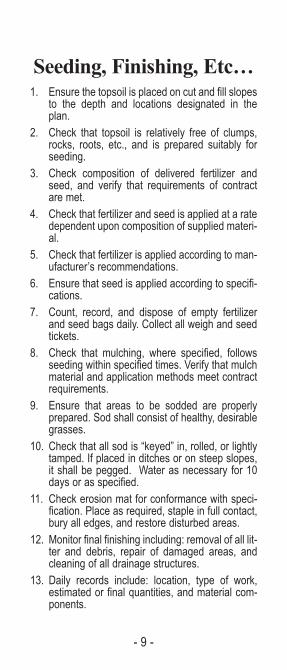
Seeding, Finishing, Etc…1. Ensure the topsoil is placed on cut and fill slopes
to the depth and locations designated in theplan.
2. Check that topsoil is relatively free of clumps,rocks, roots, etc., and is prepared suitably forseeding.
3. Check composition of delivered fertilizer andseed, and verify that requirements of contractare met.
4. Check that fertilizer and seed is applied at a ratedependent upon composition of supplied materi-al.
5. Check that fertilizer is applied according to man-ufacturer’s recommendations.
6. Ensure that seed is applied according to specifi-cations.
7. Count, record, and dispose of empty fertilizerand seed bags daily. Collect all weigh and seedtickets.
8. Check that mulching, where specified, followsseeding within specified times. Verify that mulchmaterial and application methods meet contractrequirements.
9. Ensure that areas to be sodded are properlyprepared. Sod shall consist of healthy, desirablegrasses.
10. Check that all sod is “keyed” in, rolled, or lightlytamped. If placed in ditches or on steep slopes,it shall be pegged. Water as necessary for 10days or as specified.
11. Check erosion mat for conformance with speci-fication. Place as required, staple in full contact,bury all edges, and restore disturbed areas.
12. Monitor final finishing including: removal of all lit-ter and debris, repair of damaged areas, andcleaning of all drainage structures.
13. Daily records include: location, type of work,estimated or final quantities, and material com-ponents.

- 10 -
StructuresGENERAL1. Review field controls for horizontal and vertical
alignment.2. Review utility installations and railroad
company requirements.3. Check earth foundation for correct elevation and
suitable bearing value.
PILING1. Check and document the type, length, size, heat
numbers, condition, and certification.2. Check the layout for correct location.3. Review driving operation for proper hammer,
pile cap, cushion block, hammer operation, pilesplices, and bearing formula.
4. Review subsurface exploration log with projectengineer and anticipate driving characteristics.
5. Obtain minimum penetration and bearing. Donot over-drive. Contact engineer if penetrationvaries significantly from plan.
6. After driving, check placement and alignmentand inspect for damage from driving.
7. Record unit, pile number, penetration data,driven length, cut-off length, and bearingformula.
FORMS1. Check and document condition, location,
alignment, elevations, dimension, and stability.
(Structures continued next page)

- 11 -
Structures (continued)
REINFORCEMENT1. Require proper job-site storage.2. Check condition, size, steel grade, length,
number, spacing, form clearance, support, barties, mat tie down, lap, and embedment.
3. Check anchor bolt and conduit placement.
4. Record number, length, size, and grade of bars.
CONCRETE PLACEMENT
1. Check mix, air, slump, placement, and consolidation.
2. Check form alignment during pour.
3. Collect concrete delivery tickets, verify andinitial entries. Record any addition of water, mix-ing revolutions, and time the truck completeddischarge.
4. Be aware of the time concrete was batched andof allowable time for placement.
5. Check concrete pour and consolidation.
6. Check for proper curing and cold weatherprotection.
7. Check backfill restrictions and requirements.
8. Record workers, hours, equipment, pour loca-tion, volume, air, slump, and test cylinder data.
BEAMS AND GIRDERS
1. Make visual checks for in-transit and erectiondamage, alignment tolerances, defects, anddimensional requirements.
2. Require proper job-site storage, if not set inplace on arrival.
3. Inspect bearing devices and girder seats.
4. Check in-place alignment, camber, anchor bolts,and tie downs.
5. Review field welding and bolting requirements.(Structures continued next page)

- 12 -
Structures (continued)
DECKS
1. Before beginning pour, inspect all finishing andcuring equipment for condition and adjustment.Perform “dry run” with finishing machinery.Check and record bar steel embedment anddeck thickness. Attend pre-pour conference.
2. Perform items listed under “ConcretePlacement” plus the following:
(a) During the pour, continually check and record bar steel embedment and deck thickness, also observe deflection of finishing rails and forms. Alert contractor if problems develop.
(b) Be aware of proper vibration procedure.
(c) Inspect straight edging and surface texturing.
3. Check curing and cold weather protection.
4. Daily records include: pour location, volume, air,slump and problems encountered. Also, makenecessary cylinders.
- 13 -
Geotextiles1. Review geotextile specifications. Check for:
protective shipping wrapper, tensile strength,elongation, permeability, puncture strength,apparent opening size, burst strength, abrasionresistance, ultraviolet resistance etc…
2. Check that geotextile is placed in the mannerand at the location shown on the project plans.
3. Insure that the fabric is placed on a surfacewhich is free of obstructions and debris.
4. While being placed, give consideration to over-lap, sewing, or gluing. If overlapped, the fabricshould be placed such that the preceding rolloverlaps the following roll in the direction inwhich the fill material is being spread.
5. Insure that geotextile is covered within the timespecified.
6. Insure that any sections damaged during instal-lation are repaired using a piece of fabric largeenough to cover the damaged area, and to meetoverlap requirements.
7 Note that geotextile is usually paid for by meas-uring the square yards of area covered (notincluding overlap).
8. Consider additional inspection procedures thatmay be necessary for specific geotextile uses,such as: drainage, stabilization, separation, rein-forcement, and erosion controls.

- 14 -
Bituminous SurfaceTreatment
1. Be familiar with the specifications and methods appli-cable to the work -- this type of construction proceedsrapidly!
2. Check that all testing equipment is available.3. Check asphalt distributor and all other equipment to
ensure that it meets specifications.4. Check the condition and adjustment of the asphalt pump,
spray bar, and spray nozzles. The asphalt pump shouldprovide uniform pressure. The nozzles should be set uni-formily at the proper angle from the axis of the spray bar.The height of the spary bar should provide correct over-lap of the spray from each nozzle.
5. Check the motor graders, rollers, spreader boxes, etc., toensure that they are in good operating condition.
6. Check that the roadway to be treated is smooth, com-pacted, and has a uniform grade and cross section.Existing surface should be clean and free of loose patch-es or excessive joint and crack sealing materials. Pre-level or grade uneven surfaces.
7. Inspect the stockpiled aggregate to determine the gradingof the material. Aggregate should be damp at the time ofloading onto trucks for hauling to the roadway. (Asphalt willnot readily coat dry or dusty aggregate.)
8. Test the spray bar and nozzles immediately prior to start-ing the application.
9. Keep a record of each load applied, showing area treat-ed, gallons spread, and temperature of the asphalt.
10. Check that cover stone is applied at the specified rateimmediately after the application of the asphalt. Insurethat the spread of asphalt is not extended beyond thearea that can be covered within the allowed time.
11. Cover any areas where there are skips or omissions.12. Check that rolling is conducted as soon as possible fol-
lowing application of the cover stone in order to properlyimbed the cover stone in the asphalt.
13. Broom the surface after curing to remove any loose orexcessive cover stone.
14. Daily records include: workers, hours, equipment, stationstreated, materials used, depth, width, tonnage, yield, weath-er, temperatures and problems encountered.

- 15 -
PART 2Road and HighwayMaintenance Tables
PageSuperpave and Corresponding PENNDOTCourses and Thickness . . . . . . . . . . . . . . . . . . . . . . . . . . . . 16PG Grade Determination . . . . . . . . . . . . . . . . . . . . . . . . . . . 17Skid Resistance Level (SRL) Determination Chart . . . . . . . 18
Equivalent Single Axle Loads (ESALS) Chart . . . . . . . . . . . 18
Lineal Feet Covered by a 1,000-Gallon Tank . . . . . . . . . . . 19
Gallons of Asphalt Required per Mile for Various Rates of Application . . . . . . . . . . . . . . . 20Tons of Aggregate Required per Mile for Various Rates of Application . . . . . . . . . . . . . . . 21
Cubic Yards of Material Requiredper 100 Lineal Feet . . . . . . . . . . . . . . . . . . . . . . . . . . . . . . . 22
Pounds of Aggregate Required per Square Yard. . . . . . . . . 23
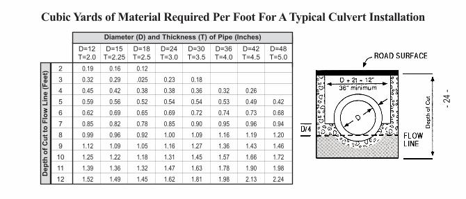
Cubic yards of Material Required per Foot for a Typical Culvert Installation . . . . . . . . . . . . . . 24
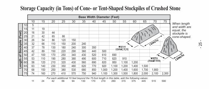
Storage Capacity (in tons) of Cone- or Tent-Shaped Stockpiles of Crushed Stone . . . . . . . . . . . . . 25
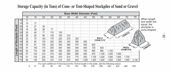
Storage Capacity (in tons) of Cone- or Tent-Shaped Stockpiles of Sand or Gravel . . . . . . . . . . . . . 26
Square Yards of Road Surface for Various Road Widths . . . . . . . . . . . . . . . . . . . . . . . . . . . 27
Mowing and Spraying Strip Widths . . . . . . . . . . . . . . . . . . . 28
Compacted Hot Mix . . . . . . . . . . . . . . . . . . . . . . . . . . . . . . . 28
Compacted Weights of Various Materials . . . . . . . . . . . . . . 29
Loose Weights of Various Materials. . . . . . . . . . . . . . . . . . . 30
Conversion Factors ( Length and Area) . . . . . . . . . . . . . . . . 31
Conversion Factors (Volume, Force, Velocity). . . . . . . . . . . 32
Conversion Factors (Common Fractions toDecimal Numbers) . . . . . . . . . . . . . . . . . . . . . . . . . . . . . . . . 33
Perimeter, Area and Volume Formulas . . . . . . . . . . . . . . . . 34

- 16-
Superpave and Corresponding PennDOT Courses and Thickness
Superpave 37.5mm Base Course
Superpave 25mm Base Course
Superpave 25mm Binder Course
Superpave 19mm Binder Course
Superpave 12.5mm Wearing Course*
Superpave 9.5mm Wearing Course *
Superpave Paving Course
Course-Graded BCBC
Typical BCBC
Typical ID-2 Binder Course
Fine-Graded ID-2 Binder Course
Coarse-Graded ID-2 Wearing
Typical ID-2 Wearing Course
Corresponding PennDOTConventional Paving Course
4.5”
3”
3”
2.5”
2”
1.5”
MinimumThickness
as designed
as designed
5.5”
4.5”
3”
2”
MaximumThickness
as designed
as designed
5.5”
4.5”
3”
2”
MaximumConstruction Lift
* When used as a wearing course, not for Scratch or Leveling. Recommended using 9.5mm for Scratch or Leveling, 60 to 110 Lb/sy
Mixture Comparison Chart Superpave Material Thickness
Superpave 9.5mm Fine-Graded Wearing Course* Typical ID Fine-Graded 1” 1.5” 1.5”

- 17 -
PG 58-28 Use where AC-10 was specified in thepast (cold weather climates).. Do notuse on steep down or up grades or inheavy truck traffic areas.
PG 64-22 Use where AC-20 was specified in thepast (most common in Pennsylvania).Can be used in any part of the stateunder most traffic conditions.
PG 76-22 Use where Polymer Modified AsphaltCement is specified. Can be used inany part of the State under heavytraffic conditions, at intersections, or atlocations where rutting has occurred inthe past.
PG Grade Determination
For example, an asphalt classified as a PG 64-22means that the asphalt will meet the high temperaturephysical property requirements of the pavement downto -8°F. PG 64-22 is the liquid asphalt (asphalt cement)that should be specified in most applications.
Placement Temperatures
PG 58-22 260°F to 310°F
PG 64-22 265°F to 320°F
PG 76-22 285°F to 330°F
* Includes Warm and Hot Mix
1. Warm Mix is a generic term for various technologiesallowing asphalt paving materials to be producedand placed at lower temperatures.
2. The temperature of warm mix asphalt (WMA) mustbe below the maximum allowable temperature ofHot Mix asphalt (HMA). See below.
3. Warm mix allows some kind of an approved additiveto be placed in the mix at the plant. The additivereduces the viscosity and increases the workabilityat a lower temperature. This allows lower mixingand placement/compaction temperatures.
4. Compaction is achieved at much lower tempera-tures. For additional information please consult yourDistricts Municipal Office, Districts Materials person-nel or your supplier .
What is Warm Mix Asphalt?

- 18 -
Skid Resistance Level (SRL)Determination Criteria
M; Blend of Hand L; Blendof G and L;Blend of E
and L
Above 10,000 Above 20,000 E
Initial or CurrentOne-Way ADT
Initial or CurrentTwo-Way ADT
SRLDesigation
2,501-10,000 5,000-20,000H; Blend of Eand M, Blend
of E & G
1,501-2,500 3,001-5,000G; Blend of Hand M; Blendof E and L
501-1,500 1,001-3,00
0-500 0-1,000 L
1 truck/day = 7,300 ESAL’s
Note: Truck/Day calculations utilizing a 1 ESAL truck,however different truck configurations have different ESAL values.
Contact your District Municipal Services or ConstructionOffice for assiastance if needed.
Practical ESAL’sComparison(20 year life)
ESAL’s = Trucks/Day
0.0 to 0.3 mil = 0 to 40
10 trucks/day = 73,000 ESAL’s
0.3 to 3. mil = 40 to 400
100 trucks/day = 730,000 ESAL’s
3. to 30. mil = 400 to 3,900
over 30. mil = over 3,900

- 19-
Lineal Feet Covered By A 1,000-Gallon TankGallons Per Square Yard
89
1011121415161820222425262830
0.1011,250
10,000
9,000
8,182
7,500
6,429
6,000
5,625
5,000
4,500
4,091
3,750
3,600
3,462
3,214
3,000
0,157,500
6,667
6,000
5,455
5,000
4,286
4,000
3,750
3,333
3,000
2,727
2,500
2,400
2,308
2,143
2,000
0.205,625
5,000
4,500
4,091
3,750
3,214
3,000
2,813
2,500
2,250
2,045
1,875
1,800
1,731
1,607
1,500
0.254,500
4,000
3,600
3,273
3,000
2,571
2,400
2,250
2,000
1,800
1,636
1,500
1,440
1,385
1,286
1,200
0.303,750
3,333
3,000
2,727
2,500
2,143
2,000
1,875
1,667
1,500
1,364
1,250
1,200
1,154
1,071
1,000
0.333,375
3,000
2,700
2,455
2,250
1,929
1,800
1,688
1,500
1,350
1,227
1,125
1,080
1,038
964
900
0.353,214
2,857
2,571
2,338
2,143
1,837
1,714
1,607
1,429
1,286
1,169
1,071
1,029
989
918
857
0.402,813
2,500
2,250
2,045
1,875
1,607
1,500
1,406
1,250
1,125
1,023
938
900
865
804
750
0.502,250
2,000
1,800
1,636
1,500
1,286
1,200
1,125
1,000
900
818
750
720
692
643
600
0.601,875
1,667
1,500
1,364
1,250
1,071
1,000
938
833
750
682
625
600
577
536
500
0.701,607
1,429
1,286
1,169
1,071
918
857
804
714
643
584
536
514
495
459
429
0.801,406
1,250
1,125
1,023
938
804
750
703
625
563
511
469
450
433
402
375
0.901,250
1,111
1,000
909
833
714
667
625
556
500
455
417
400
385
357
333
1.001,125
1,000
900
818
750
643
600
563
500
450
409
375
360
346
321
300
1.25900
800
720
655
600
514
480
450
400
360
327
300
288
277
257
240
1.50750
667
600
545
500
429
400
375
333
300
273
250
240
231
214
200
2.00563
500
450
409
375
321
300
281
250
225
205
188
180
173
161
150

- 20-
Gallons of Asphalt Required Per Mile for Various Application Rates
89
1011121415161820222425262830
0.10469
528
587
645
704
821
880
939
1,056
1,173
1,291
1,408
1,467
1,525
1,643
1,760
0.15704
792
880
968
1,056
1,232
1,320
1,408
1,584
1,760
1,936
2,112
2,200
2,288
2,464
2,640
0.20939
1,056
1,173
1,291
1,408
1,643
1,760
1,877
2,112
2,347
2,581
2,816
2,933
3,051
3,285
3,520
0.251,173
1,320
1,467
1,613
1,760
2,053
2,200
2,347
2,640
2,933
3,227
3,520
3,667
3,813
4,107
4,400
0.301,408
1,584
1,760
1,936
2,112
2,464
2,640
2,816
3,168
3,520
3,872
4,224
4,400
4,576
4,928
5,280
0.331,564
1,760
1,956
2,151
2,347
2,738
2,933
3,129
3,520
3,911
4,302
4,693
4,889
5,084
5,476
5,867
0.351,643
1,848
2,053
2,259
2,464
2,875
3,080
3,285
3,696
4,107
4,517
4,928
5,133
5,339
5,749
6,160
0.401,877
2,112
2,347
2,581
2,816
3,285
3,520
3,755
4,224
4,693
5,163
5,632
5,867
6,101
6,571
7,040
0.502,347
2,640
2,933
3,227
3,520
4,107
4,400
4,693
5,280
5,867
6,453
7,040
7,333
7,627
8,213
8,800
0.602,816
3,168
3,520
3,872
4,224
4,928
5,280
5,632
6,336
7,040
7,744
8,448
8,800
9,152
9,856
10,560
0.703,285
3,696
4,107
4,517
4,928
5,749
6,160
6,571
7,392
8,213
9,035
9,856
10,267
10,677
11,499
12,320
0.803,755
4,224
4,693
5,163
5,632
6,571
7,040
7,509
8,448
9,387
10,325
11,264
11,733
12,203
13,141
14,080
0.904,224
4,752
5,280
5,808
6,336
7,392
7,920
8,448
9,504
10,560
11,616
12,672
13,200
13,728
14,784
15,840
1.004,693
5,280
5,867
6,453
7,040
8,213
8,800
9,387
10,560
11,733
12,907
14,080
14,667
15,253
16,427
17,600
1.255,867
6,600
7,333
8,067
8,800
10,267
11,000
11,733
13,200
14,667
16,133
17,600
18,333
19,067
20,533
22,000
1.507,040
7,920
8,800
9,680
10,560
12,320
13,200
14,080
15,840
17,600
19,360
21,120
22,000
22,880
24,640
26,400
2.009,387
10,560
11,733
12,907
14,080
16,427
17,600
18,773
21,120
23,467
25,813
28,160
29,333
30,507
32,853
35,200
Road Width (Feet)
Gallons Per Square Yard

- 21-
Tons of Aggregate Required Per Mile For Various Application Rates
89
1011121415161820222425262830
37
8
9
10
11
12
13
14
16
18
19
21
22
23
25
26
512
13
15
16
18
21
22
23
26
29
32
35
37
38
41
44
716
18
21
23
25
29
31
33
37
41
45
49
51
53
57
62
819
21
23
26
28
33
35
38
42
47
52
56
59
61
66
70
1023
26
29
32
35
41
44
47
53
59
65
70
73
76
82
88
1228
32
35
39
42
49
53
56
63
70
77
84
88
92
99
106
1535
40
44
48
53
62
66
70
79
88
97
106
110
114
123
132
2047
53
59
65
70
82
88
94
106
117
129
141
147
153
164
176
2559
66
73
81
88
103
110
117
132
147
161
176
183
191
205
220
3070
79
88
97
106
123
132
141
158
176
194
211
220
229
246
264
3582
92
103
113
123
144
154
164
185
205
226
246
257
267
287
308
4094
106
117
129
141
164
176
188
211
235
258
282
293
305
329
352
45106
119
132
145
158
185
198
211
238
264
290
317
330
343
370
396
50117
132
147
161
176
205
220
235
264
293
323
352
367
381
411
440
100235
264
293
323
352
411
440
469
528
587
645
704
733
763
821
880
Road Width (Feet)
Pounds Per Square Yard

- 22-
Cubic Yards of Material Required Per 100 Lineal Feet
89
1011121415161820222425262830
0.5”1.2
1.4
1.5
1.7
1.9
2.2
2.3
2.5
2.8
3.1
3.4
3.7
3.9
4.0
4.3
4.6
0.75”1.9
2.1
2.3
2.5
2.8
3.2
3.5
3.7
4.2
4.6
5.1
5.6
5.8
6.0
6.5
6.9
1.0”2.5
2.8
3.1
3.4
3.7
4.3
4.6
4.9
5.6
6.2
6.8
7.4
7.7
8.0
8.6
9.3
1.5”3.7
4.2
4.6
5.1
5.6
6.5
6.9
7.4
8.3
9.3
10.2
11.1
11.6
12.0
13.0
13.9
2.0”4.9
5.6
6.2
6.8
7.4
8.6
9.3
9.9
11.1
12.3
13.6
14.8
15.4
16.0
17.3
18.5
2.5”6.2
6.9
7.7
8.5
9.3
10.8
11.6
12.3
13.9
15.4
17.0
18.5
19.3
20.1
21.6
23.1
3.0”7.4
8.3
9.3
10.2
11.1
13.0
13.9
14.8
16.7
18.5
20.4
22.2
23.1
24.1
25.9
27.8
3.5”8.6
9.7
10.8
11.9
13.0
15.1
16.2
17.3
19.4
21.6
23.8
25.9
27.0
28.1
30.2
32.4
4.0”9.9
11.1
12.3
13.6
14.8
17.3
18.5
19.8
22.2
24.7
27.2
29.6
30.9
32.1
34.6
37.0
4.5”11.1
12.5
13.9
15.3
16.7
19.4
20.8
22.2
25.0
27.8
30.6
33.3
34.7
36.1
38.9
41.7
5.0”12.3
13.9
15.4
17.0
18.5
21.6
23.1
24.7
27.8
30.9
34.0
37.0
38.6
40.1
43.2
46.3
6.0”14.8
16.7
18.5
20.4
22.2
25.9
27.8
29.6
33.3
37.0
40.7
44.4
46.3
48.1
51.9
55.6
8.0”19.8
22.2
24.7
27.2
29.6
34.6
37.0
39.5
44.4
49.4
54.3
59.3
61.7
64.2
69.1
74.1
10.0”24.7
27.8
30.9
34.0
37.0
43.2
46.3
49.4
55.6
61.7
67.9
74.1
77.2
80.2
86.4
92.6
12.0”29.6
33.3
37.0
40.7
44.4
51.9
55.6
59.3
66.7
74.1
81.5
88.9
92.6
96.3
103.7
111.1
Road Width (Feet)
Cubic Yards of Loose Aggregate Required for Various Depths (Inches)

Pounds of Aggregate Required Per Square Yard
1,8001,9002,0002,1002,2002,3002,4002,5002,6002,7002,8002,9003,0003,1003,2003,3003,4003,5003,600
1”505356586164676972757881838689929497100
2”100106111117122128133139144150156161167172178183189194200
3”150158167175183192200208217225233242250258267275283292300
4”200211222233244256267278289300311322333344356367378389400
5”250264278292306319333347361375389403417431444458472486500
6”300317333350367383400417433450467483500517533550567583600
7”350369389408428447467486506525544564583603622642661681700
8”400422444467489511533556578600622644667689711733756778800
9”450475500525550575600625650675700725750775800825850875900
10”5005285565836116396676947227507788068338618899179449721,000
11”5505816116426727037337647948258568869179479781,0081,0391,0691,100
12”6006336677007337678008338679009339671,0001,0331,0671,1001,1331,1671,200
- 23-
Pounds of Compacted Aggregate Per Square Yard for Various Depths (Inches)
Pounds of Aggregate Per Cubic Yard
D=12T=2.0
D=15T=2.25
D=18T=2.5
D=24T=3.0
D=30T=3.5
D=36T=4.0
D=42T=4.5
D=48T=5.0
- 24-
Cubic Yards of Material Required Per Foot For A Typical Culvert Installation
23456789101112
0.19
0.32
0.45
0.59
0.62
0.85
0.99
1.12
1.25
1.39
1.52
0.16
0.29
0.42
0.56
0.69
0.82
0.96
1.09
1.22
1.36
1.49
0.12
.025
0.38
0.52
0.65
0.78
0.92
1.05
1.18
1.32
1.45
0.23
0.38
0.54
0.69
0.85
1.00
1.16
1.31
1.47
1.62
0.18
0.36
0.54
0.72
0.90
1.09
1.27
1.45
1.63
1.81
0.32
0.53
0.74
0.95
1.16
1.36
1.57
1.78
1.98
0.26
0.49
0.73
0.96
1.19
1.43
1.66
1.90
2.13
0.42
0.68
0.94
1.20
1.46
1.72
1.98
2.24
Diameter (D) and Thickness (T) of Pipe (Inches)Depth of C
ut to Flow Line (Feet)
1015202530354045505560657075
10511162126323742475358636874
15
19304254667889100110120140150160
20
446586110130150170190210230250270
25
86120150180220250280320350380410
30
150200240290340380430480530570
35
240300360430490560620680750
40
350440520600690770850940
45
5006107108209201,0001,100
50
6908209501,1001.2001,300
55
9101,1001,2001,4001,500
60
1,2001,4001,6001,800
65
1,5001,7002,000
70
1,9002,100
75
2,300
Storage Capacity (in Tons) of Cone- or Tent-Shaped Stockpiles of Crushed Stone
Length of Stockpile (Feet)
Base Width Diameter (Feet)
11 24 42 66 94 130 170 210 260 315 375 445 515 590For each additional 10 feet beyond the 75-foot length in this table, add the following values:
When lengthand width areequal, the stockpile iscone-shaped.
- 25-
1015202530354045505560657075
10510141924283338434752576166
15
1727384859708091100110120130140
20
39587796120130150170190210230250
25
77110140170200220250280310340370
30
130180220260300340390430470510
35
210270330380440500560610670
40
320390470540620690770840
45
4505406407408309301,000
50
6207308509701,1001,200
55
8209601,1001,2001,400
60
1,1001,2001,4001,600
65
1,4001,6001,800
70
1,7001,900
75
2,100
Storage Capacity (in Tons) of Cone- or Tent-Shaped Stockpiles of Sand or Gravel
Length of Stockpile (Feet)
Base Width Diameter (Feet)
. 9 21 38 59 85 115 150 190 235 285 340 400 460 530For each additional 10 feet beyond the 75-foot length in this table, add the following values:
When lengthand width areequal, the stockpile iscone-shaped.
- 26-
- 27 -
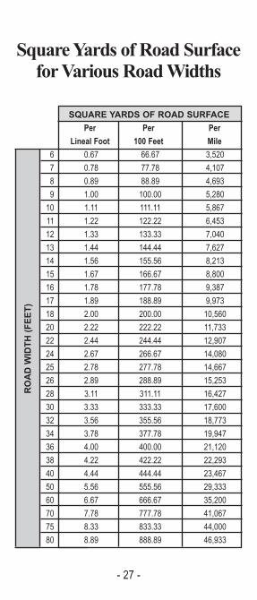
Square Yards of Road Surfacefor Various Road Widths
SQUARE YARDS OF ROAD SURFACEPer Per Per
Lineal Foot 100 Feet Mile
6 0.67 66.67 3,520
7 0.78 77.78 4,107
8 0.89 88.89 4,693
9 1.00 100.00 5,280
10 1.11 111.11 5,867
11 1.22 122.22 6,453
12 1.33 133.33 7,040
13 1.44 144.44 7,627
14 1.56 155.56 8,213
15 1.67 166.67 8,800
16 1.78 177.78 9,387
17 1.89 188.89 9,973
18 2.00 200.00 10,560
20 2.22 222.22 11,733
22 2.44 244.44 12,907
24 2.67 266.67 14,080
25 2.78 277.78 14,667
26 2.89 288.89 15,253
28 3.11 311.11 16,427
30 3.33 333.33 17,600
32 3.56 355.56 18,773
34 3.78 377.78 19,947
36 4.00 400.00 21,120
38 4.22 422.22 22,293
40 4.44 444.44 23,467
50 5.56 555.56 29,333
60 6.67 666.67 35,200
70 7.78 777.78 41,067
75 8.33 833.33 44,000
80 8.89 888.89 46,933
ROAD WIDTH (FEE
T)

- 28 -
Mowing and SprayingStrip Widths
If you have a strip of a certain width to mow orspray, how many acres are in one mile or how manymiles must you travel to equal one acre?
43,560 SF = 1 Acre
Approximate Miles Acres in Traveled toa Mile Equal One Acre
1 0.12 8.25
2 0.24 4.13
3 0.36 2.75
4 0.48 2.06
5 0.61 1.65
6 0.73 1.38
7 0.85 1.18
8 0.97 1.03
9 1.09 0.92
10 1.21 0.83
12 1.45 0.69
14 1.70 0.59
16.5 2.00 0.50
Compacted Hot MixDepth Compacted Square Yards
(Inches) Per Ton1.0 18.0
1.5 12.0
2.0 9.0
2.5 7.1
3.0 6.0
STRIP WIDTH (FEE
T)

- 29 -
Compacted Weightsof Various Materials
Pounds Pounds Apx. PoundsType of Per Per Per Sq. YardMaterial Cubic Foot Cubic Yard Per 1” DepthTrap 122 3,300 92
Rock 127 3,420 95
131 3,530 98
Granite or 113 3,060 85
Limestone 118 3,180 88
122 3,300 92
Sandstone 105 2,830 79
109 2,950 82
113 3,060 85
118 3,180 88
Sand 105 2,830 79
109 2,950 82
113 3,060 85
118 3,180 88
Slag 70 1,890 53
83 2,240 62
96 2,590 72
109 2,950 82
Cement 115 3,100 86
Bituminous 130 3,510 97
145 3,910 109
160 4,320 120

- 30 -
Loose Weights ofVarious Materials
Pounds Pounds Apx. PoundsType of Per Per Per Sq. YardMaterial Cubic Foot Cubic Yard Per 1” DepthTrap 96 2,590 72
Rock 100 2,690 75
103 2,780 77
Granite or 90 2,410 67
Limestone 93 2,500 69
96 2,590 72
Sandstone 82 2,220 62
86 2,320 64
90 2,410 66
93 2,500 70
Sand 97 2,630 73
101 2,740 76
106 2,850 79
110 2,960 82
Slag 55 1,480 41
65 1,760 49
76 2,040 57
86 2,320 64
Cement 91 2,480 69
Bituminous 100 2,700 75
116 3,130 87
128 3,460 96

Conversion FactorsLENGTH
To Convert (A) To (B) Multiply (A) ByInches Feet 0.0833
Inches Yards 0.028
Feet Inches 12
Feet Yards 0.33
Feet Rods 0.06
Yards Inches 36
Yards Feet 3
Yards Rods 0.18
Rods Inches 198
Rods Feet 16.5
Rods Yards 5.5
Miles Feet 5,280
Miles Yards 1,760
Miles Rods 320
- 31 -
AREATo Convert (A) To (B) Multiply (A) By Square Inches Square Feet 0.007
Square Feet Square Inches 144
Square Feet Square Yards 0.11
Square Yards Square Inches 1,296
Square Yards Square Feet 9
Square Yards Square Rods 0.03
Square Rods Square Feet 272.25
Square Rods Square Yards 30.25
Acres Square Feet 43,560
Acres Square Yards 4,840
Acres Square Rods 160

- 32 -
Conversion FactorsVOLUME
To Convert (A) To (B) Multiply (A) ByCubic Feet Cubic Inches 1,728
Cubic Feet Cubic Yards 0.04
Cubic Feet Gallons 7.48
Cubic Yards Cubic Feet 27
Cubic Yards Gallons 202
Quarts Pints 2
Quarts Gallons 0.25
Gallons Pints 8
Gallons Quarts 4
Gallons Cubic Feet 0.13
FORCETo Convert (A) To (B) Multiply (A) By
Ounces Pounds 0.06
Pounds Ounces 16
Tons (short) Pounds 2,000
Tons (metric) Pounds 2,204
VELOCITYTo Convert (A) To (B) Multiply (A) By
Miles/Hour Feet/Minute 88
Miles/Hour Feet/Second 1.47
- 33 -
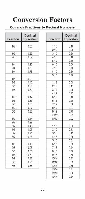
Conversion FactorsCommon Fractions to Decimal Numbers
Decimal Fraction Equivalent
1/2 0.50
1/3 0.332/3 0.67
1/4 0.252/4 0.503/4 0.75
1/5 0.202/5 0.403/5 0.604/5 0.80
1/6 0.172/6 0.333/6 0.504/6 0.675/6 0.83
1/7 0.142/7 0.293/7 0.434/7 0.575/7 0.716/7 0.86
1/8 0.132/8 0.253/8 0.384/8 0.505/8 0.636/8 0.757/8 0.88
Decimal Fraction Equivalent
1/10 0.102/10 0.203/10 0.304/10 0.405/10 0.506/10 0.607/10 0.708/10 0.809/10 0.90
1/12 0.082/12 0.173/12 0.254/12 0.335/12 0.426/12 0.507/12 0.588/12 0.679/12 0.7510/12 0.8311/12 0.92
1/16 0.062/16 0.133/16 0.194/16 0.255/16 0.316/16 0.387/16 0.448/16 0.509/16 0.5610/16 0.6311/16 0.6912/16 0.7513/16 0.8114/16 0.8815/16 0.94

- 34 -
Perimeter, Area, and Volume Formulas
PERIMETER = PScalene Triangle P = a + b + c
Isosceles Triangle P = 2a + b
Equilateral Triangle P = 3s
Quadrilateral Triangle P = a + b + c + d
Rectangle P = 2l + 2w
Square P = 4s
Circle P = 3.14 x d
AREA = ARectangle A = lw
Square A = lw or A = s2
Parallelogram A = bh
Triangle A = 1/2 bh
Trapezoid A = 1/2 h (b1 + b2)
Circle A = 3.14 x r2
Cube A = 6e2
VOLUME = VCylinder V = bh
Rectangular Solid V = lwh
Cube V = e3
Circular Cylinder V = 3.14 x r2 x h
Pyramid V = 1/3 bh
Cone V = 1/3 bh or 1/3 3.14r2 h
Sphere V = (4 x 3.14 x r3)/3

- 35 -
PART 3Asphalt Paving Inspection
Check ListPage
Preliminary Responsibilities . . . . . . . . . . . 36Milling . . . . . . . . . . . . . . . . . . . . . . . . . . . . 36Equipment Inspections . . . . . . . . . . . . . . . 37Tack Coat . . . . . . . . . . . . . . . . . . . . . . . . . 38Traffic Control, Weather Requirements . . 39Paving Operation . . . . . . . . . . . . . . . . . . . 40Placement of Mix . . . . . . . . . . . . . . . . . . . 41Compaction . . . . . . . . . . . . . . . . . . . . . . . 42Construction Transverse Joints . . . . . . . . 42

- 36 -
PreliminaryResponsibilities
DOCUMENT REVIEWo Bid Specifications.o Special Provisions.o Construction Manual.o Traffic Control Plan (TCP).
COORDINATION OF WORKo Utility companies are contacted and
work is coordinated.o If necessary, manhole elevations are
adjusted.o Any planned road excavations are
completed before paving begins.o Local businesses’ access times are
arranged.o Local businesses’ entrances and exits
are discussed.
FIELD REVIEWo I am wearing appropriate safety gear.o Necessary repair areas are marked.o Necessary repairs are made before
paving begins.
Millingo Pavement is milled to proper depth.o Milling equipment does not rip or tear
the surface.o Dust is controlled during milling.o Check for traffic signal sensor loop
detectors. o Coordinate with Traffic Light
maintenance provider before milling begins.

- 37 -
Equipment InspectionsHAUL TRUCKS
o Back-up alarms working.o No fuels or oil leaks.o Tarps are required.o Releasing agent is drained completely
before mix is placed in truck.o Inspect hauling trucks for foreign debris
each day before loading.
PAVERo Flow control gates are adjusted to allow
right amount of material flow.o Screed surface is smooth.o Leading edge of screed set slightly
higher about 3/8 inch than trailing edge.o If an extension is used, auger is same
length as extension.o Depth screws properly set at beginning
of operation.o Grade and slope set properly.o If skis are used, sensing device is mounted
between 6 1/2 to 11 1/2 feet
ROLLERSo Steel-wheel rollers’ drums are smooth.o Scrapers and mats are in good condition.o Steel-wheel rollers’ nozzles are working
properly.o No oil or fuel leaks under roller.o Pneumatic-tire rollers’ tires properly
inflated, within 5 psi of each other.o Pneumatic-tire rollers’ have a working
weight capacity of at least 300 lbs per inch of width of tread.
HAND TOOLSo Lutes are used for joint construction, not rakes.o While in use, hand tools are
cleaned with a putty knife, not diesel fuel.

- 38 -
Tack CoatMATERIAL
o Approved type of tack coat is used as specified by contract documents.
o Tack has been sampled and submitted for testing.
PRELIMINARYo Surface is clean and dry before
application.o Tack is heated within proper
temperature range prior to application.
EQUIPMENTo Nozzles are clean and unplugged.o Nozzles angled in same direction.
APPLICATIONo Tack is applied evenly and uniformly.o Tack all vertical faces.o Tack is applied at specified application
rate.o More tack is not applied that can be
covered in the same day.o Traffic and dirt are kept off the tack
coat.o When emulsions are used, the material
loses its water content before the mixis placed (turns from brown to blackand becomes sticky and tacky).

- 39 -
Traffic Controlo Signs and devices used match traffic
control plan.o Set-up complies with the latest version
of Publication 213.o Flaggers MUST be trained.o Flaggers do not hold traffic too long.o Unsafe conditions, if any, are reported
to supervisor.
o Signs are removed or covered when they no longer apply.
Weather Requirementso Local specs checked for minimum air
and surface temperature requirements.o Any applicable calendar restrictions are
observed.o Paving does not begin if rain is likely.

- 40 -
Paving OperationDELIVERY OF MIX
o Ticket collected from each haul truck.o Time mix is received and where it is
placed recorded on ticket.o Mix meets minimum temperature
requirement usually 260 to 285 degrees Fahrenheit.
o There are no lumps, blue smoke, or steam (indications that mix is too hot orcold. If so, may call for rejection).
o There are no uncoated particles, and the mix is not soupy, stiff or dull (indications of inadequate asphalt) If so, may call for rejection.
o There are no pockets of fine or coarseaggregates (indicates segregation) If so, may call for rejection.
o Station numbers noted to determineamount of material to be placed.
o Haul trucks maintain a constant supply of material to paver.
- 41 -
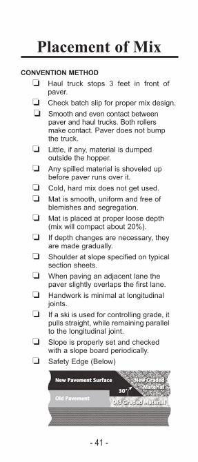
Placement of MixCONVENTION METHOD
o Haul truck stops 3 feet in front ofpaver.
o Check batch slip for proper mix design.o Smooth and even contact between
paver and haul trucks. Both rollers make contact. Paver does not bump the truck.
o Little, if any, material is dumped outside the hopper.
o Any spilled material is shoveled up before paver runs over it.
o Cold, hard mix does not get used.o Mat is smooth, uniform and free of
blemishes and segregation.o Mat is placed at proper loose depth
(mix will compact about 20%).o If depth changes are necessary, they
are made gradually.o Shoulder at slope specified on typical
section sheets.o When paving an adjacent lane the
paver slightly overlaps the first lane.o Handwork is minimal at longitudinal
joints.o If a ski is used for controlling grade, it
pulls straight, while remaining parallelto the longitudinal joint.
o Slope is properly set and checked with a slope board periodically.
o Safety Edge (Below)
- 42 -
Compactiono When rollers reverse direction, they
stop gradually and reverse smoothly without scuffing, pushing or marring the mat.
o Rollers do not stop on the hot mat(except to reverse direction).
o Rollers proceed in as straight a line as possible. Turns are smooth and gradual not sharp.
o On super elevations, rolling starts onlow side, with each successive pass 6 to 12 inches to the high side.
o Density is checked and meets agency’s minimum requirements.
ConstructingTransverse Joints
o Material is cut away at a point wherethe required depth and slope are maintained.
o If paper is used, the paper extends the full length and width of the taper.
o Transition is formed at the proper taper.o Surrounding pavement is clean
before paving begins again.o Face of joint is vertical.o Joint face, and area where taper was
made are tacked.o Excess material is removed after
paver goes by.o Joint receives same compaction as
the rest of the mat.o Transition is smooth. Any high or low
spots are corrected.

- 43 -
PART 4Chip Seal Application
Check ListPage
Preliminary Responsibilities . . . . . . . . . 44 Equipment Inspections . . . . . . . . . . . . . 45Surface Preparation, Weather RequirementsDetermining Application Rates . . . . . . . 46Checking Application Rates . . . . . . . . . 47Traffic Control, Oil Application, Aggregate Application. . . . . . . . . . . . . . 48Rolling, Truck Operation, Longitudinal Joints,Transverse Joints . . . . . . . . . . . . . . . . . 49Brooming, Opening Chip Seal to Traffic. . . . . . . . . 50Common Problems and Solutions . . . . 50

- 44 -
PreliminaryResponsibilities
DOCUMENT REVIEWo Bid Specificationso Special Provisionso Construction Manualo Traffic Control Plan (TCP)
MATERIALS CHECKSo Type of oil to be used is compat-
ible with Aggregateso Oil is from an approved sourceo Oil is sampled and submitted for
testing, if requiredo All aggregates are close to the
same size
o Aggregates are clean
o Aggregates used with emulsionsare in surface-damp condition
o Test strip if required

- 45 -
Equipment InspectionsBROOM
o Bristles are proper length.o Broom can be adjusted vertically
to avoid excess pressure.
DISTRIBUTORo Distributor is properly calibrated.o Nozzles are uniformly angled 15 to
30 degrees from spray bar.o Spray checked for uniformity
and overlap before applicationsbegins.
AGGREGATE SPREADER
o Aggregate spreader is calibrated.o Gate controls work properly.o Scalping screen is in good condition.
ROLLERSo Roller tire pressures comply with
manufacturers specifications.o Pressure is uniform from one tire
to the next.
ALL EQUIPMENTo All equipment is free of leaks.

- 46 -
Surface Preparationo Existing surface inspected for
drainage problems.o Potholes are repaired and cracks are
sealed.
o Rutting, bleeding, and corrugations are repaired.
o Existing surface is completely clean and dry.
o Do not apply scratch coat prior to the chip seal application.
Weather Requirementso Air and surface temperatures meet
agency requirements.o Air and surface temperatures
checked at coolest location on project.
o Application of oil does not begin if excessive wind will cause problems.
o Application of oil does not begin if rainis likely.
DeterminingApplication Rateso Agency guidelines and requirements
are followed.o More oil is applied to dried-out and
porous surfaces.
o Less oil is applied to smooth, non-porous,and asphalt-rich surfaces.
o Less oil is applied on roads with hightraffic volumes.

- 47 -
Checking ApplicationRates
OIL - METHOD Ao Weight of 1 square yard pan or
non-woven geotextile material is recorded.o 1 square yard pan or non-woven
geotextile material placed on road surface.
o Distributor applies oil over pan or material o Pan and oil or geotextile material and
oil is weighed.o Weight of pan or material without oil is
subtracted from weight of pan or material with oil.
OIL - METHOD Bo Gallons of oil in distributor is measure
while distributor is parked on level ground.
o Distributor applies oil to test section withknown surface area.
o Gallons applied divided by square yardscovered equal gallons per square yard.
AGGREGATES
o Weight of 1 square yard tarp is recorded.
o 1 square yard tarp placed on road surface.
o Chipper applies aggregates over tarp.o Tarp and aggregates are weighed.o Weight of tarp without aggregates is
subtracted from weight of tarps with aggregates.

- 48 -
Traffic Controlo Signs and devices used match traffic
control plan.o Set-up complies with the latest version
of Publication 213.o Flaggers do not hold traffic too long.o Unsafe conditions, if any, are reported
to the supervisor.o Pilot car leads traffic slowly [25 mph
or less] over fresh chip seals.o Signs are removed or covered when
they no longer apply.
Oil Applicationo Application starts and stops with neat,
straight edges.o Application starts and stops on building
paper.o Application appears uniform.o Application is stopped as soon as
problems are detected.
Aggregate Applicationo Enough trucks are on hand to keep a
steady supply of chips for the spreader.o Application starts and stops with neat,
straight edges.o Application starts and stops on building
paper. o Aggregate spreader follows closely [30
yards or less] behind disributor when emulsion is used.
o Spreader travels slowly enough to avoidaggregates rolling when they hit the surface.
o No oil is on top of the Aggregates.
- 49 -
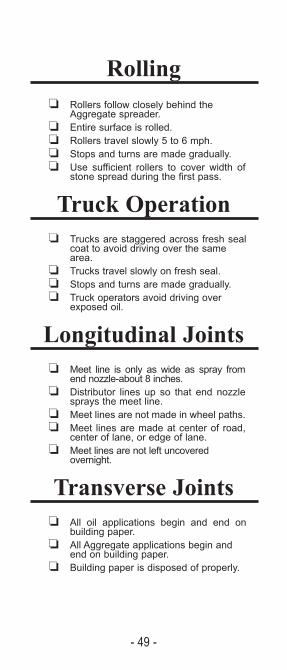
Rollingo Rollers follow closely behind the
Aggregate spreader.o Entire surface is rolled.o Rollers travel slowly 5 to 6 mph.o Stops and turns are made gradually.o Use sufficient rollers to cover width of
stone spread during the first pass.
Truck Operationo Trucks are staggered across fresh seal
coat to avoid driving over the same area.
o Trucks travel slowly on fresh seal.o Stops and turns are made gradually.o Truck operators avoid driving over
exposed oil.
Longitudinal Jointso Meet line is only as wide as spray from
end nozzle-about 8 inches.o Distributor lines up so that end nozzle
sprays the meet line.o Meet lines are not made in wheel paths.o Meet lines are made at center of road,
center of lane, or edge of lane.o Meet lines are not left uncovered
overnight.
Transverse Jointso All oil applications begin and end on
building paper.o All Aggregate applications begin and
end on building paper.o Building paper is disposed of properly.

- 50 -
Broomingo Brooming begins as soon as possible.o Brooming does not begin until sufficient
bond has formed between oil and chips.o Brooming does not dislodge aggregate.
Opening Chip Seal toTraffic
o Traffic travels slowly [25 mph or less] over fresh seal coat.
o Reduced speed limit signs are usedwhen pilot cars are not used.
Common Problemsand Solutions
1. Excessive splattering of oil: Spray pressure too high
2. Non-uniform oil application:Spray pressure too low; clogged noz zles.
3. Concentrations of oil:Leak in distributor plumbing; Excessive application rate.
4. Exposed oil after Aggregate application:Clogged or malfunctioning gate.
5. Excessive Aggregates:Malfunctioning gate;Overloading the spreader.
6. Oil on top of Aggregate:Spreader speed too fast improper truckor roller operation.
7. Concentration of oil in wheel only: Traffic on too soon or excessive application rate.
- 51 -
PART 5Concrete Paving
Check ListPage
Concrete Paving. . . . . . . . . . . . . . . . . . . . 52Sidewalks, Bikeways, Curb, and Gutter . . 57Forms . . . . . . . . . . . . . . . . . . . . . . . . . . . . 59Flowable Fill . . . . . . . . . . . . . . . . . . . . . . . 60Pervious Concrete . . . . . . . . . . . . . . . . . . 61

- 52 -
Concrete Paving1. Subgrade
(a) Check that base is graded and compactedproperly.
(b) Any soft spots in base have been corrected(c) Properly referenced for line and grade(d) Trimmed to correct elevation and cross-slope
using outside control from referenced lines(string line)
(e) Low points are properly located and marked
2. Review field controls for line and grade andbecome familiar with paving sequence.
3. Verify that utilities work and conduits arecomplete. Pre-locate utility fixtures to be pouredin pavement.
4. Load transfer devices(a) Placed within tolerances(b) Firmly fastened down(c) Correctly located(d) Locations marked for saw crew(e) Properly lubricated(f) Dowels correct size and length(g) Dowels located parallel to the longitudinal axis
5. Grade moist before placing concrete
6. Check the following equipment(a) Paver(1) Check hydraulic vibrators for oil leaks(2) Assure all vibrators working properly(3) Check Bars inserters correctly(4) Correct width
(b) Texturing equipment(c) Curing machine(d) Air Meters
7. Have all ADA issues been addressed

- 53 -
8. Verify Concrete mix design
(a) Prescription mix or reviewed by engineer
(b) Class and percent of fly ash (when included)
(c) Admixtures
(d) Admixture proportions
(e) Water/cement ratio
(f) Slump
(g) Target air
(h) Strength
9. Paving Gaps
(a) Properly located and marked
(b) Payment procedures agreed upon
10. All driveways located and marked
11. Concrete delivery when mixed in a central plant
(a) High early loads noted
(b) Random check of discharge within time limits
12. Transverse and longitudinal joint layoutdiscussed and agreed with contractor
(a) Joint spacing is proper for thickness specified
(b) Length to width ratios not exceeded
(c) Acute angles greater that 60 degrees
13. Concrete delivery when mixed in a transit/truckmixer
(a) Concrete tickets
(a) Tickets with each load
(a) All information on each ticket
(b) Amount of added water documented
(c) When water is added, is water/cement ratioexceeded
(d) Transit/truck mixers using the correct numberof revolutions before discharging and afteradding water and/or admixtures
(e) High early loads noted

- 54 -
14. During Concrete placement
(a) Check temperature of concrete within specification
(b) Check air temperatures
(c) Placed so minimum rehandling is required
(d) Signs of segregation
(e) Slump (consistency) visually similar for each load
(f) Discharge complete within specified time limits
(g) All concrete removed from non-agitating trucks
(h) Foot prints in fresh concrete vibrated (whenoccurring behind screed)
(i) When placing a transverse construction joint, isit at least four (4) feet from any transversesawed (weakened plane) contraction joint
(j) Proper vibrations performed around manholes,inlets, etc.
(k) Proper operation of hand/spud vibrators
15. Finished pavement
(a) Proper width
(b) Proper thickness (using probing technique)
(c) Proper crown
(d) Proper super-elevation (when required)
(e) Edge slump within specifications
16. Testing
(a) Taking air tests per specifications
(b) Making cylinders for open to traffic
(c) Making cylinders for strength verifications
(d) Handling cylinders per specifications
(e) Taking slump tests if required per specifications
17. Longitudinal construction joints
(a) Properly located
(b) At lane lines (unless otherwise specified)
(c) Accommodation for manholes, etc.

- 55 -
18. Tie bars (when required)
(a) Inserted by approved method
(b) Inserted at proper location
(c) Epoxy coated
(d) Correct size
(e) Correct length
(f) Correct depth
(g) Correct spacing
(h) Proper treatment at transverse joints (either leftout or not bent out)
19. Longitudinal sawed (weakened plane) joints
(a) Properly located
(b) Accommodation for manholes, etc.
(c) At lane lines (unless otherwise specified)
20. Transverse sawed (weakened plane) joints
(a) Properly located and marked
(b) Manholes, inlets, etc. accommodated
(c) Matches adjacent joints
(d) Matches tolerances for load transfer devices
21. Expansion joints (Pre-formed joint filler material placed as required on the plans)
22. Paver leaving an acceptable finish
23. Any hand finishing required
24. Straight-edging shows smoothness within tolerance
25. Any water being added to the surface to assistfinishing
26. Burlap drag being kept at proper moisture (if being used)
27. Stationing being stamped into the pavement at the correct location (when required)
28. Texturing consistent

- 56 -
29. Cold weather protection required (contractor& municipality agree on basis for determining low temperature)
30. Material available to protect the pavement from rain.
31. Curing
(a) Cure placed within the specified time
(b) Application rate correct
(c) Placed on both vertical and horizontal surface
(d) Been approved
32. Check Joint Sawing Operation
(a) Saw joints been properly located and marked
(b) Within specified tolerance over load transferdevices (if specified)
(c) Joints sawed before cracking occurs
(d) Spalling occurring when joints are sawed.
(e) Proper width and depth
(f) Accommodate manholes, inlets, etc.
33. Sealing
(a) Concrete cured properly before sealing starts
(b) Approved materials
(c) Sealant placed to the specified tolerances
(d) Material recessed 3/16 of an inch
34. Pavement strength at 3000 PSI before opening to traffic

- 57 -
Sidewalks, Bikeways,Curb and Gutter
1. Subgrade
(a) Graded and compacted properly
(b) Soft spots identified and corrected
(c) Cross slope, elevation, and alignment correct
2. Reinforcing
(a) Required
(b) If so, what kind
(c) Correctly placed
3. Forms (when used)
(a) Set to proper line and elevation
(b) Set per grade stakes
(c) Firmly set and staked
(d) Correct dimensions
(e) Lightly oiled for concrete release
(f) Correctly set for inlet sections, handicap rampsand driveways
(g) Correctly set to handle all drainage per plantypical section
4. Placing integral or non-integral curb & gutter
(a) Has grade been trimmed to correct cross slopand elevation
(b) Is gradeline correct per grade stakes
(c) Are inlet sections, handicap ramps, anddriveways correctly located and marked
(d) Proper drainage to inlets
(e) Is pan being constructed to spill or catch pertypical section.
(f) Is alignment correct
(g) Does extruded section meet plan typical
- 58 -
5. Concrete
(a) Approved Class
(b) Test requirements being met
(c) Acceptable finish being achieved
(d) Properly consolidated
(e) Grade moist before placing concrete
(f) Finish accomplished without use of water
(g) Curing compound of an approved type, appliedat appropriate time and rate
(h) Cold weather protection necessary
6. Joints
(a) Edged where required
(b) Expansion material of correct type placedwhere required
(c) Expansion material extending full depth
(d) Types and locations match joints in adjacentconcrete
(e) Transverse type per plan
(f) Expansion material an approved type
7. Is backfill being started at correct time (verify ifcure time or proper strength)

- 59 -
Forms1. Forms mortar tight and sufficiently rigid to prevent
excessive deflections.
2. Metal forms of adequate thickness and design toremain true to shape
3. Metal forms present a smooth surface and the jointsalign properly
4. Inside surfaces cleaned of all dirt, mortar, and foreignmaterials
5. Acceptable form oil is being used
6. All materials, (e.g. conduits, drains, utility block-outs,anchoring devices, etc.) to be embedded placed andadequately secured
7. Backforms being used properly
8. All dirt, chips, sawdust, water, or other foreign materi-als been removed from within the forms
9. Wood forms oiled or moistened prior to concreteplacement
10.Concrete obtained required strength and/or minimumelapsed time per specifications prior to form removal

- 60 -
Flowable FillCONSTRUCTION
Placement
1. If necessary, construct formwork of adequate strengthto withstand lateral pressure exerted by fluid material(PUB 408).
2. Do not place material through flowing water. Removeand replace any flowable fill damaged by water or rain-fall.
3. Verify that there are no lumps in the material. If lumpsare present they should be broken up.
4. Verify that all bleed water has dissipated prior to placing next lift of material.
5. Protect surface of material from frost, erosion, or otherdamage with an approved material
• Structural Backfill – Place flowable backfill in lifts toprevent lateral pressures from exceeding the resistancecapacity of the structure. Protect structure drains fromcontamination of flowable backfill materials with appro-priate geotextile material. Protect structure, utilities, etc.from movement or misalignment during placing ofmaterial.
• Pipe Bedding & Backfill – Place adequate support toprovide minimum required bedding from trench bottomto bottom of pipe. Protect pipe from backfill materialintrusion by wrapping appropriate geotextile materialaround pipe. Prevent floating of pipe by placing fillmaterial in lifts or with sand bags, etc. to ballast the pipeuntil lift is set.
• Utility Trench Backfill – Provide adequate tie downs orweights to prevent pipe from floating during materialplacement.
Opening the Pavement to Traffic
• For Types A, B, and C material do not open to trafficuntil at least one hour after bleed water has dissipatedand as allowed by the Representative.
• For Type D material open to traffic as approved by theRepresentative.
- 61 -
Pervious ConcreteCONSTRUCTION
Placement - Manual
1. Ensure that sub-grade and base material has beenproperly prepared and possesses suitable perme-ability.
2. Base material should be level (free of ruts) and mois-tened prior to concrete placement.
3. Forms should be of adequate strength to supportplacing equipment. Enough pins/stakes should beused to prevent lateral movement of forms.
4. Concrete should be placed as quickly as possibleand as close to its final position as practical.
5. Pumping is not recommended.
6. Concrete should be placed “high” and compacted toproper grade. A roller screed is recommended forplacement purposes.
7. Additional compaction may be required along theform edges to maintain structural integrity after theforms have been removed.
8. Jointing in green concrete may be accomplished witha concrete saw or through the use of a jointing toolreferred to as a “pizza cutter” (preferred method).
9. Joint depth to be D/3 or D/4.
10.Joint spacing should follow the recommendation ofthe project designer.

- 62 -
CURING
1. Curing should commence almost immediately (within 20 minutes) after concrete has been placedand jointed.
2. Traditional membrane curing compounds are notrecommended.
3. A 6 mil. (or thicker) polyethylene sheet should beused for curing purposes. Misting the surface of theconcrete prior to placement of the plastic is suggested if the concrete has lost its sheen.
4. The cover should be secured to ensure the concrete remains covered. Dirt, sand or other granular materials are not recommended.
5. Plastic should remain in place for a minimum of 7days. If supplementary materials are used in theconcrete mix, cure time may be extended to 10days.
6. The pavement should not be trafficked during thecuring period.
7. Cold/Hot weather protection techniques should be applied as necessary.

- 63 -
PENNDOT Municipal Services
Bureau of Municipal Services . . . . (717) 787-2183Programs & Services Division . . . . (717) 772-1772Financial Consulting Division . . . . . (717) 783-8588The Agility Center . . . . . . . . . . . . . (717) 705-1333
District Supervisors Phone Numbers
This publication is brought to you by the Pennsylvania Department ofTransportation, Bureau of Municipal Services and Bureau of Planning and
Research with support from the Federal Highway Administration.
District 1 - 814) 678-7142 | 255 Elm Street | Oil City, PA 16301
District 2 - (814) 765-0408 | 1924-30 Daisy Street | P.O. Box 342 Clearfield, PA 16830
District 3 - (570) 368-4239| 715 Jordan Avenue | P.O. Box 218 Montoursville, PA 17754
District 4 - (570) 963-4052 | 55 Keystone Industrial ParkDunmore, PA 18512
District 5 - (610) 871-4151 | 1002 Hamilton StreetAllentown, PA 18101-1013
District 6 - (610) 205-6541 | 7000 Geerdes BoulevardKing of Prussia, PA 19406
District 8 - (717) 787-4839 | 2140 Herr StreetHarrisburg, PA 17103-1699
District 9 - (814) 696-7221 | 1620 North Juniata StreetHollidaysburg, PA 16648
District 10 - (724) 357-7986 | 2550 Oakland Avenue | P.O. Box 429 Indiana, PA 15701-0429
District 11 - (412) 429-4813 | 45 Thoms Run RoadBridgeville, PA 15017
District 12 - (724) 439-7136 | P.O. Box 459 | N. Gallatin Avenue, Ext. Uniontown, PA 15401
“SAFETY IS NO ACCIDENT.”Here is a link to available training:http://www.toolboxtopics.com/Construction/index.htm