Pocket Guide to cable management - Atlas Copco · Welcome to our pocket guide to cable management....
24
Pocket guide to cable management
Transcript of Pocket Guide to cable management - Atlas Copco · Welcome to our pocket guide to cable management....
Pocket guide to cable management

2 P O C K E T G U I D E T O C A B L E M A N A G E M E N T
CABLE MANAGEMENTWelcome to our pocket guide to cable management. You are strongly recommended to read it prior to planning and in-stalling the cables provided with equipment from Atlas Copco Industrial Technique.
As with many industrial systems, cables are a main failure point especially in applications where the cables are subject to repetitive motion. Atlas Copco has developed this pocket guide to help you find effective solutions to your facilities unique cable needs. It includes information developed from Atlas Copco’s many years of industrial experience and will help in limiting your cable relative failures.
For additional information or assistance, please contact your Atlas Copco representative.
3P O C K E T G U I D E T O C A B L E M A N A G E M E N T
CONTENTS
Chapter ................................................................................................. Page
1. Definition of cable management ...................................................... 4
2. Cable management for fixtured tools/torque tubes ...................... 5
2.1 Overview of fixtured tools ........................................................... 5
2.2 Setting tool cable length in relation to restraint cables ............ 6
2.3 How to fixture an angle tool ....................................................... 6
2.4 Special tools ................................................................................. 6
3. Cable management for handtooling using a cable balancer ......... 7
4. Cable management for resting the tool .......................................... 9
4.1 Tools tray ....................................................................................... 9
4.2 Tool hook ....................................................................................... 9
4.3 Suspension yoke .......................................................................... 9
5. Cables .................................................................................................10
5.1 Benefits of a flat cable ............................................................... 10
5.2 Bending radius for tool cables .................................................. 12
5.3 Recommended cable length ..................................................... 13
6. Protection of cables using cable accessories ................................ 14
6.1 Accessories ................................................................................. 14
7. Securing the cable ........................................................................... 15
7.1 Use common sense when securing cables .............................. 15
7.2 Method of securing the cable .................................................... 17
8. Check points ..................................................................................... 18
8.1 Before installation ...................................................................... 18
8.2 During the installation ................................................................19
8.3 After the installation ................................................................... 21

4 P O C K E T G U I D E T O C A B L E M A N A G E M E N T
1. DEFINITION OFCABLE MANAGEMENTCables are used in conjunction with all Atlas Copco tools and assembly equipment, including: handheld tools, fixtured hand tools or when spindle “motors only” are provided for incor-poration into various types of machine automation.
In the case of fastening equipment, cables connect the following functions:• Power supply• Controller• Nutrunner• Accessory
Tool tray, see page 9.

5P O C K E T G U I D E T O C A B L E M A N A G E M E N T
2. CABLE MANAGEMENT FORFIXTURED TOOLS/TORQUE TUBES2.1 Overview of fixtured tools
Controller
Atlas Copco controller stand
Cable connector
Whip cable
Mid full stop
Restraint cable adjusted in field
Cable connector

6 P O C K E T G U I D E T O C A B L E M A N A G E M E N T
2.2 Setting tool cable length in relation torestraint cables
(Hand tool cable shown).
Restraint cable length 26” nominal (shown extended).
Tool cable linear min. length 28‘ as measured from top of the cable shoe center (shown extended).
Note:This view shows a typical hand tool cable installation on Atlas Copco cable shoe(s).
• Final adjustment should be made on site to suit condi-tions.
• Tool cable lengths may vary due to foot traffic or work station requirements and will then require a shorter restraint cable adjustment.
• Restraint cable length must always be shorter than tool cable length to limit cable stress (as shown).
2.3 How to fixture an angle type tool
(Hand tool Tensor ST shown).
2.4 Special tools
Specials are best defined as all other tool options, including– H.A.D. (Hold and Drive) tools– F.S. (Flush Socket) tools– Tools fitted with external electric accessories, such as Bar
Code scanner, P-Set selector, I/O bit selector, etc.– and any other adaption, except for the standard ETV
angle tools.
In cases where these special types of tool are being consid-ered for mounting to any form of end effector, torque tube etc. and/or the direct fitment of a reaction device onto any part of the tool body, you are strongly advised to seek the support and approval of Atlas Copco Tools.
The illustration serves as a basic guideline for mounting options. As you can see in the illustration, the mounting options are broken down into three categories:
Primary
Secondary
No Mounting Allowed

7P O C K E T G U I D E T O C A B L E M A N A G E M E N T
3. CABLE MANAGEMENT FOR HANDTOOLING USING A CABLE BALANCER
A cable balancer helps to manage the excess cable when the tool and cable are not extended.
Also shown above is the use of a cable clamp bracket. This bracket is used to attach the cable balancer to the cable.
A cable balancer is equipped with a “stop” (shown above) and its tension is adjustable, thus enabling a specific set up at the workstation to suit the operator.
Note:Adjust restraint cable lengths and electrical cable length such that the length of the restraint cable between cable trolleys is shorter than that of the electrical cables between trolleys.
8 P O C K E T G U I D E T O C A B L E M A N A G E M E N T
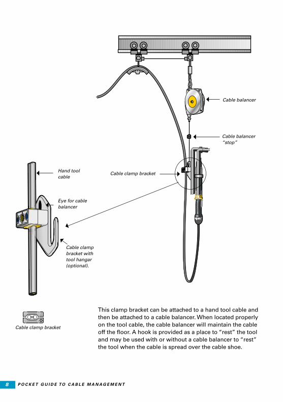
This clamp bracket can be attached to a hand tool cable and then be attached to a cable balancer. When located properly on the tool cable, the cable balancer will maintain the cable off the floor. A hook is provided as a place to “rest” the tool and may be used with or without a cable balancer to “rest” the tool when the cable is spread over the cable shoe.
Cable balancer
Cable balancer “stop”
Hand tool cable
Eye for cable balancer
Cable clamp bracket with tool hangar (optional).
Cable clamp bracket
Cable clamp bracket

9P O C K E T G U I D E T O C A B L E M A N A G E M E N T
4. CABLE MANAGEMENT WITHREGARD TO RESTING THE TOOL
4.1 Tool tray
When a hand tool is not attached to a torque tube balancer, cable balancer or support/suspending element, a tool tray or tool hook should be provided. Hand tools and cables are sub-jected to rough treatment and misuse when the operator is not provided with a convenient place to rest the tool safely.
4.2 Tool hook
Atlas Copco offers a bracket that clamps onto the tool cable to provide a place to hang the tool. Suspension yokes are avail-able for attaching to the tool. They have an eyelet that can be used to hang the tool by means of a hook. (See page 4).
4.3 Suspension yoke
A “suspension yoke” is available for almost all Atlas Copco hand tools. There are various types of yoke to suit the re-quirements of different tools.
Suspension yokes
Hand tool using suspension yoke.
10 P O C K E T G U I D E T O C A B L E M A N A G E M E N T
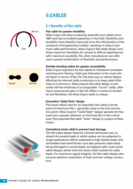
Round
Round
Flat
Tensor
High
Kevlar
Low
5. CABLES
5.1 Benefits of flat cable
Flat cable for greater durabilityAtlas Copco has been producing assembly tool cables since1987 and has unrivalled experience in the field. Flexibility and durability have steadily improved since the introduction of the company’s first-generation cables, resulting in today’s opti-mum cable performance. Atlas Copco’s flat-cable design com-bines maximum flexibility (for access to difficult applications) with maximum durability. No other manufacturer can offer such a potent combination of flexibility and performance.
Smaller bending radius for greater accessibilityAtlas Copco engineers its tool cables to withstand consistentand long-term flexing. Cable size (diameter) is the most criti-cal factor in terms of flex life. The best way to reduce fatigueaffecting the internal cable conductors is to keep cable thick-ness to a minimum. Atlas Copco’s flat-cable design is justunder half the thickness of a comparable “round” cable, offer-ing an exponential gain in flex life. When it comes to durabil-ity and flexibility, the Atlas Copco cable is unique.
Innovative ‘Cable Twist’ designThe most critical area for an assembly tool cable is at the point of maximum flex – generally close to the tool connec-tion point. Atlas Copco’s “Cable Twist” design spreads the flex load over a greater distance, to minimize flex in the critical area. This patented flat-cable “twist” design is unique to Atlas Copco.
Centralized strain relief to prevent lead damageThe flat-cable design features a Kevlar-reinforced core, toabsorb the tensile loads to which cables can be subjected intough applications. When subjected to high tensile loads, thiscentralized load-relief Kevlar core also prevents cable leadsbeing damaged or compressed, as happens with most roundcable designs which have the strain relief outside the cableleads. For maximum signal integrity, the flat cable design also ensures optimum separation of high and low voltage conduc-tors.
11P O C K E T G U I D E T O C A B L E M A N A G E M E N T
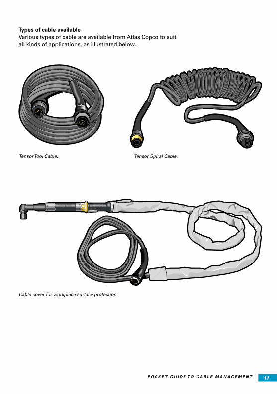
Types of cable availableVarious types of cable are available from Atlas Copco to suit all kinds of applications, as illustrated below.
Tensor Tool Cable. Tensor Spiral Cable.
Cable cover for workpiece surface protection.

12 P O C K E T G U I D E T O C A B L E M A N A G E M E N T
5.2. Bending radius for tool cables
All Atlas Copco tool cables are designed to be bent or flexed. However, a related and frequently asked question is – how tightly can you bend a cable without damaging it?
The answer depends primarily on the specific cable being considered for the tool involved.
What is the minimum bending radius? Take a look at the illustration to the left: In the drawing, a cable is being bent around a radius of 5”. The bend could be the result of pulling a cable around a curve in an above ground conduit or underground duct. It could also be the result of laying the cable in the bend of a cable tray.
The radius of a circle is always half the diameter. In the wire and cable industry, we usually give the minimum bending ra-dius as a multiple of the cable diameter.
Below you can find a table of minimum bending radii for vari-ous cable types:
The rated voltage of the cables mentioned below should not exceed 0.6/1 kV.
Thus 4 d for an 8 mm diameter cable in a tray means that the minimum bending radius is 32 mm.
Cable material = Polyurethane
Testing the cable by bending it 180 degrees.
270 deg.
0 deg.
90 deg.Radius
Cable
180 deg.
5”
1”
Flexible cables Up to 8 mm diameter Over 8 to 12 mm diameter
Over 12 to 20 mm diameter
Cables in trays 4 d 5 d 5 d
Cables in free mode 7 d 8 d 12 d
Forced operation (wind) 7 d 7 d 7 d
Chain operation 6 d 6 d 7 d
Rolling detour 10 d 10 d 10 d
Designation Chemical VDE Max. workingtemperature, °C
Tensile strength[N/mm2]
Stretch %
PUR Polyurethane 11 Y 80 35 – 50 500 – 700

13P O C K E T G U I D E T O C A B L E M A N A G E M E N T
5.3 Recommended cable length
This section describes recommended cable lengths for Atlas Copco tool cables for Tensor ST/SR/STR/ETX/QST. The cable is used to make the connection between the following com-ponents:
• Controller
• Tool (straight, angle, pistol, fixtured)
The cables for Tensor ST and Tensor SL are designed to carry digital-only signals between the controller and the tool card. The characteristics of the digital signals enable transmission in longer cables compared to analogue signals.
In the table below you can see the recommended cable length for our handheld and fixtured tools:
Tool type Signal type Recommendedcable length [m]
Tensor S Analogue 20
ETX Analogue 25
QST Digital 40
Tensor ST 31/61/81, SL, SR, STR Digital 50
Tensor ST10 Digital 30
14 P O C K E T G U I D E T O C A B L E M A N A G E M E N T
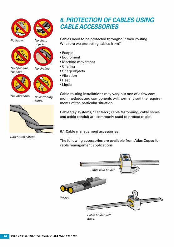
6. PROTECTION OF CABLES USINGCABLE ACCESSORIES
Cables need to be protected throughout their routing.What are we protecting cables from?
• People• Equipment• Machine movement• Chafing • Sharp objects• Vibration• Heat• Liquid
Cable routing installations may vary but one of a few com-mon methods and components will normally suit the require-ments of the particular situation.
Cable tray systems, “cat track”, cable festooning, cable shoes and cable conduit are commonly used to protect cables.
No liquid.
No open fire.No heat.
No sharp objects.
No vibrations. No corroding fluids.
No chafing.
Don’t twist cables.
6.1 Cable management accessories
The following accessories are available from Atlas Copco for cable management applications.
Cable with holder.
Cable holder with hook.
Wraps.

15P O C K E T G U I D E T O C A B L E M A N A G E M E N T
7. SECURING THE CABLE
7.1 Use common sense when securing cables
Typically, the greatest wear and tear on cables is caused by securing them incorrectly. The improper use of tie wraps, clamps, straps, tape, etc., are common causes of cable problems.
Examples:
• Over-tightening – tears cable covers, causes kinks and can create “hot spots”.
• Incorrect securing may restrict cable movement and exert a corkscrew effect on the cable.
• Incorrect securing can place excessive strain on cable connectors.
• Use of “tie wraps”, straps, tape, etc., may place unnecessary strain on cables. Cables that move need
reasonable freedom of movement.
• Poor placement when securing cables forces repetitive bending at a given point rather than over a length of
cable. Try to bend/flex over a greater length of cable.
• Remember it is important to stretch out and relax cable(s) prior to securing in order to remove cable “memory” fol-lowing shipping/packing.
Use common sense when securing cables!
Do not over-tighten the cable.
16 P O C K E T G U I D E T O C A B L E M A N A G E M E N T
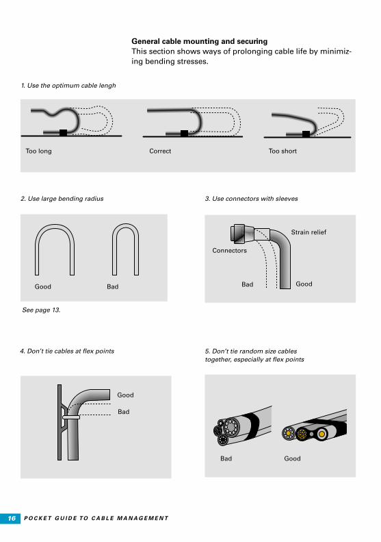
1. Use the optimum cable lengh
Too long Correct Too short
2. Use large bending radius 3. Use connectors with sleeves
Connectors
Strain relief
Bad GoodBadGood
4. Don’t tie cables at flex points
Bad
Good
5. Don’t tie random size cablestogether, especially at flex points
General cable mounting and securingThis section shows ways of prolonging cable life by minimiz-ing bending stresses.
Bad Good
See page 13.
17P O C K E T G U I D E T O C A B L E M A N A G E M E N T
7.2 Methods of securing the cable
Hand tools and cablesMoving in, out, over, under and around a given fastening operation exposes cables to sharp edges, rough pointed surfaces, pinch points and snags. These types of situation commonly cause the greatest abuse to cables. Attention to protecting cables from excessive exposure to these cable damaging conditions needs to be evaluated when designing the cable management system.
Whip cablesA specific fastening operation may have foreseeable cable damaging aspects which are unavoidable. In these instances a shorter “whip cable” can be provided with the expectation of replacing this intermediate, less expensive cable as required. The use and proper placement of a “whip cable” will also make cable replacement less time consuming. The use and stocking of a spare “whip cable” is recommended for practi-cally any application, whether it be a hand tool or a fixtured tool operation.
Panel/controller locationPanel/controller location must be determined in order to best specify cable length(s). Although panels for fixtured tools (non hand tools) are typically lagged to the floor, hand tool controllers may not be in a fixed position. Controllers may be mounted on Atlas Copco “stands” which may then be fastened to the floor or casters used. Controllers can also be mounted on a frame equipped with trolleys for use on a tool rail, allowing it to be moved along with the tool on the tool rail. Ultimately the length of cable should be specified by identifying the panel/controller location, the allocation for cable routing and the amount of “working travel” required by the operator.
18 P O C K E T G U I D E T O C A B L E M A N A G E M E N T
8. CHECK LIST
8.1 Before installation
1. The cables must be prepared for installation by removing any twists, bends or kinks in the cable.
2. When unpacking the cables, remove any tie wraps used during shipping.
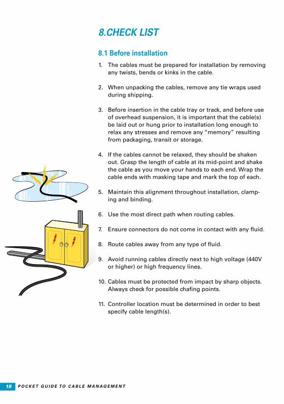
3. Before insertion in the cable tray or track, and before use of overhead suspension, it is important that the cable(s) be laid out or hung prior to installation long enough to relax any stresses and remove any “memory” resulting from packaging, transit or storage.
4. If the cables cannot be relaxed, they should be shaken out. Grasp the length of cable at its mid-point and shake the cable as you move your hands to each end. Wrap the cable ends with masking tape and mark the top of each.
5. Maintain this alignment throughout installation, clamp-ing and binding.
6. Use the most direct path when routing cables.
7. Ensure connectors do not come in contact with any fluid.
8. Route cables away from any type of fluid.
9. Avoid running cables directly next to high voltage (440V or higher) or high frequency lines.
10. Cables must be protected from impact by sharp objects. Always check for possible chafing points.
11. Controller location must be determined in order to best specify cable length(s).
19P O C K E T G U I D E T O C A B L E M A N A G E M E N T
8.2 During the installation
1. The minimum recommended bending radius of the cable should not be exceeded (see page 12 ). When multiple cables are in use, the cable with the greatest overall di-mension should be used in calculating minimum radius. It is best to follow the rule that “big bends are best”. The minimum bending radius must be increased when re-peated flexing will occur at given point on the cables.
2. Protect cable connectors from impact that will cause damage, such as dropping cables from elevated cable tray to floor level.
3. Do not weave cables between each other or wrap them around each other. Cables and/or hoses from other tools should not share hangers, trolleys, etc.
4. Do not secure cables at a connector, leave at least 5 inches between connector and cable straps, cable
clamp, etc. with the optimum goal of zero movement (including vibration) at the connector.
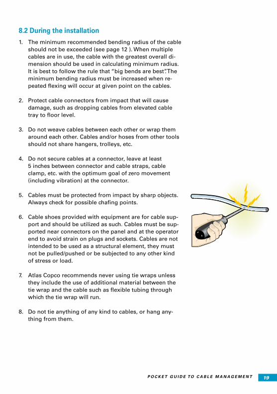
5. Cables must be protected from impact by sharp objects. Always check for possible chafing points.
6. Cable shoes provided with equipment are for cable sup-port and should be utilized as such. Cables must be sup-ported near connectors on the panel and at the operator end to avoid strain on plugs and sockets. Cables are not intended to be used as a structural element, they must not be pulled/pushed or be subjected to any other kind
of stress or load.
7. Atlas Copco recommends never using tie wraps unless they include the use of additional material between the tie wrap and the cable such as flexible tubing through which the tie wrap will run.
8. Do not tie anything of any kind to cables, or hang any-thing from them.
20 P O C K E T G U I D E T O C A B L E M A N A G E M E N T
9. Cables hung using a festooning type system must be secured to the individual cable trolley/saddle, avoiding sharp bends and be positioned to eliminate or minimize any torsion twisting. Cables must be routed properly to ensure ease of movement and eliminate any foreseeable wear or damage.
10. Strain relief cables should be used between cable trol-leys to eliminate pulling and stretching of cables by the operator when repeatedly positioning tool.
11. Cable loops should be consistent in length and typically not exceed 5 feet in depth between trolley saddles. Sufficient trolleys should be present in the system to support the entire length of moving cable and allow relaxed stacking of cable loops when the tool is in the idle, retracted, position.
12. Rail stops, end of travel stops and rotation limits should be incorporated into the system to prevent excessive cable wear and protect against over travel damage and torsional twisting.
13. Restraint cable length must always be shorter than tool cable length to limit cable stress.
21P O C K E T G U I D E T O C A B L E M A N A G E M E N T
8.3 After the installation
1. Route cables away from the operator, clear of worker traffic and away from any suspension obstructions.
2. Do not tie or hang anything whatsoever from cables.
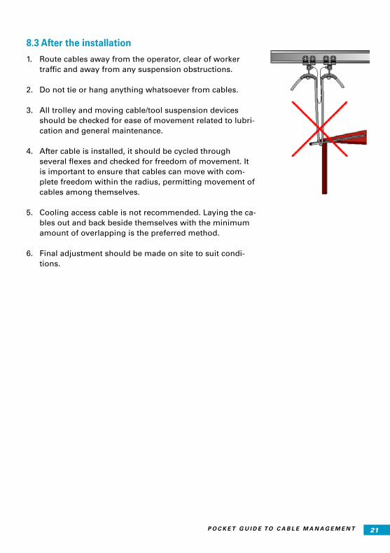
3. All trolley and moving cable/tool suspension devices should be checked for ease of movement related to lubri-cation and general maintenance.
4. After cable is installed, it should be cycled through several flexes and checked for freedom of movement. It is important to ensure that cables can move with com-plete freedom within the radius, permitting movement of cables among themselves.
5. Cooling access cable is not recommended. Laying the ca-bles out and back beside themselves with the minimum amount of overlapping is the preferred method.
6. Final adjustment should be made on site to suit condi-tions.

22 P O C K E T G U I D E T O C A B L E M A N A G E M E N T
POCKET GUIDES FROMATLAS COPCO INDUSTRIAL TECHNIQUE
Title Ordering No.
Air line distribution 9833 1266 01
Air motors 9833 9067 01
Cable management 9833 1640 01
Drilling with handheld machines 9833 8554 01
Error proofed production 9833 1437 01
Grinding 9833 8641 01
LEAN 9853 8215 01
Percussive tools 9833 1003 01
Power Tool Ergonomics (book) 9833 1162 01
Pulse tools 9833 1225 01
Riveting technique 9833 1124 01
Screwdriving 9833 1007 01
Statistical analysis technique 9833 8637 01
Testing and calibration in assembly technology 9833 1720 01
The art of ergonomics 9833 8587 01
Tightening technique 9833 8648 01
Vibrations in grinders 9833 9017 01
Vibration exposure assessment for power tools 9833 1508 01


9833
164
0 01
20
16:1
Jet
lag
/Bo
ard
wal
k. P
rin
ted
in S
wed
en.
© A
tlas
Co
pco
Ind
ust
rial
Tech
niq
ue
AB
. All
rig
hts
res
erve
d. N
o p
art
of
this
pu
blic
atio
n m
ay b
e re
pro
du
ced
wit
ho
ut
the
pri
or
per
mis
sio
n o
f th
e co
pyr
igh
t h
old
er.
COMMITTED TO SUSTAINABLE PRODUCTIVITY
www.atlascopco.com