PO-2033C LCD Panel Controller Board Support TTL … Panel Controller Board Support TTL & LVDS Panel...
12
PO-2033C LCD Panel Controller Board Support TTL & LVDS Panel For 4.3”~22” Digital LCD panel (Support resolution up to 1680*1050)
Transcript of PO-2033C LCD Panel Controller Board Support TTL … Panel Controller Board Support TTL & LVDS Panel...
PO-2033C LCD Panel Controller Board Support TTL & LVDS Panel
For 4.3”~22” Digital LCD panel (Support resolution up to 1680*1050)

PO-2033C SPEC
PO-2033C Specification Control board dimension: 108 (L) *81.5(W) * 16(H) (unit: mm)
Main application
1. PC LCD monitor 2. Industrial PC Monitor 3. Medical Use Monitor
Supporting for the resolution of LCD panel from to 4.3” 480*272 to 22” WSXGA(1680*1050)
Support LCD panel brand: AUO, CMO, LG, CPT, AMPIRE, DATAIMAGE, INNOLUX, SAMSUNG, HITACHI, SHARP, NEC.
Page 1 of 11

PO-2033C SPEC
Support PC Timing
Item Resolution H Freq.(kHz) V Freq.(Hz) 1 640*400 31.5 70 2 720*400 31.5 70
31.5 60 37.9 72 3 640*480 37.5 75 37.9 60 48.1 72 4 800*600/800*48046.9 75 48.4 60 56.5 70 5 1024*768 60 75
63.5 60 6 1280*1024
80 75 7 1680*1050 66.15 60
Main function
a. Support Input/ Output: 1. Audio input / output 2*1W(Optional) 2. VGA input 3. Support LVDS/ TTL interface output
b. Operating Function: 1. OSD control. (support Multilanguage) 2. IR remote (optional) 3. Auto-adjustment functions for frequency, phase, position and white-balance
c. Power: 1. Panel Power Selection: 3.3V, 5V, 12V 2. Standby Power Consumption: <1W 3. Power Input: 12V DC or 12V DC+5V DC
d. Operation Temperature: 0~50 degree C e. Storage Temperature; -10~+60 degree C
Page 2 of 11
PO-2033C SPEC
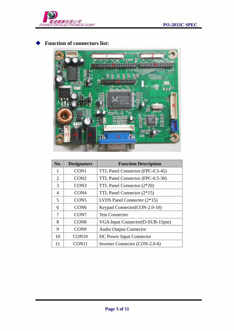
Function of connectors list:
No. Designators Function Description 1 CON1 TTL Panel Connector (FPC-0.5-45) 2 CON2 TTL Panel Connector (FPC-0.5-30) 3 CON3 TTL Panel Connector (2*20) 4 CON4 TTL Panel Connector (2*15) 5 CON5 LVDS Panel Connector (2*15) 6 CON6 Keypad Connector(CON-2.0-10) 7 CON7 Test Connector 8 CON8 VGA Input Connector(D-SUB-15pin) 9 CON9 Audio Output Connector 10 CON10 DC Power Input Connector 11 CON11 Inverter Connector (CON-2.0-6)
Page 3 of 11

PO-2033C SPEC
Pin define for TTL panel connector (CON1) 45PIN/0.5 FPC Pin Symbol Pin Symbol
1 GND 24 OG5 2 D-SHCLK 25 OG4 3 GND 26 GND 4 D-DE 27 OG3 5 GND 28 OG2 6 D-VSYNC 29 OG1 7 GND 30 OG0 8 D-HSYNC 31 GND 9 GND 32 OR7 10 NC 33 OR6 11 GND 34 OR5 12 OB7 35 OR4 13 OB6 36 GND 14 OB5 37 OR3 15 OB4 38 OR2 16 GND 39 OR1 17 OB3 40 OR0 18 OB2 41 PANEL-VCC 19 OB1 42 PANEL-VCC 20 OB0 43 NC 21 GND 44 NC 22 OG7 45 NC 23 OG6
Page 4 of 11

PO-2033C SPEC
Pin define for TTL connector (CON2)30PIN/0.5 FPC Pin Symbol Pin Symbol
1 GND 24 ER5 2 EB7 25 ER4 3 EB6 26 GND 4 EB5 27 ER3 5 EB4 28 ER2 6 GND 29 ER1 7 EB3 30 ER0 8 EB2 9 EB1 10 EB0 11 GND 12 EG7 13 EG6 14 EG5 15 EG4 16 GND 17 EG3 18 EG2 19 EG1 20 EG0 21 GND 22 ER7 23 ER6
Page 5 of 11

PO-2033C SPEC
Pin define for TTL connector (CON3)2*20 Pin Symbol Pin Symbol
1 PANEL-VCC 21 GND 2 PANEL-VCC 22 OG0 3 PANEL-VCC 23 OG1 4 PANEL-VCC 24 OG2 5 GND 25 OG3 6 GND 26 OG4 7 D-VSYNC 27 OG5 8 GND 28 OG6 9 D-HSYNC 29 OG7 10 GND 30 GND 11 D-DE 31 OB0 12 GND 32 OB1 13 OR0 33 OB2 14 OR1 34 OB3 15 OR2 35 OB4 16 OR3 36 OB5 17 OR4 37 OB6 18 OR5 38 OB7 19 OR6 39 GND 20 OR7 40 D-SHCLK
Page 6 of 11

PO-2033C SPEC
Adaptor Board pin define 1. For Hitachi: TX20D16VM2BAA, 40 Pin/ 0.5 FPC
Pin Symbol Pin Symbol 1 VDD 21 G4 2 VDD 22 G3 3 VDD 23 VSS 4 VDD 24 G2 5 NC 25 G1 6 DTMG 26 G0 7 VSS 27 VSS 8 NC 28 R5 9 VSS 29 R4 10 (IC) 30 R3 11 VSS 31 VSS 12 B5 32 R2 13 B4 33 R1 14 B3 34 R0 15 VSS 35 (IC) 16 B2 36 VSS 17 B1 37 VSS 18 B0 38 DCLK 19 VSS 39 VSS 20 G5 40 VSS
Page 7 of 11
PO-2033C SPEC
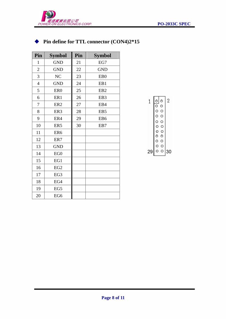
Pin define for TTL connector (CON4)2*15
Pin Symbol Pin Symbol 1 GND 21 EG7 2 GND 22 GND 3 NC 23 EB0 4 GND 24 EB1 5 ER0 25 EB2 6 ER1 26 EB3 7 ER2 27 EB4 8 ER3 28 EB5 9 ER4 29 EB6 10 ER5 30 EB7 11 ER6 12 ER7 13 GND 14 EG0 15 EG1 16 EG2 17 EG3 18 EG4 19 EG5 20 EG6
Page 8 of 11

PO-2033C SPEC
Pin define for LVDS connector (CON5) 2*15
Pin Symbol Pin Symbol 1 LCDVCC 16 RXOC+ 2 LCDVCC 17 RXO3- 3 LCDVCC 18 RXO3+ 4 GND 19 RXE0- 5 GND 20 RXO0+ 6 GND 21 RXO1- 7 RXO0- 22 RXO1+ 8 RXO0+ 23 RXO2- 9 RXO1- 24 RXO2+ 10 RXO1+ 25 GND 11 RXO2- 26 GND 12 RXO2+ 27 RXEC- 13 GND 28 RXEC+ 14 GND 29 RXE3-
15 RXOC- 30 RXE3+
Pin define for keypad connector(CON6) 10 PIN/2.0 pitch Pin Symbol Description 1 POWER Power on/off 2 LED_R To the red LED 3 LED_G To the green LED 4 GND GND, to the GROUND 5 + VOL+, next 6 - VOL-, previous 7 MENU Menu 8 AUTO Auto adjustment (color, position) 9 K5 Spare key 10 K6 Spare key
Page 9 of 11
PO-2033C SPEC
Pin define for Test connector(CON7) Pin Symbol
1 5V 2 RXD 3 TXD 4 GND
Pin define for VGA input connector(CON8)
Pin Symbol Pin Symbol
1 R 9 NC 2 G 10 GND 3 B 11 GND 4 GND 12 DDC_SDA 5 GND 13 HS 6 R-GND 14 VS 7 G-GND 15 DDC_SCL 8 B-GND
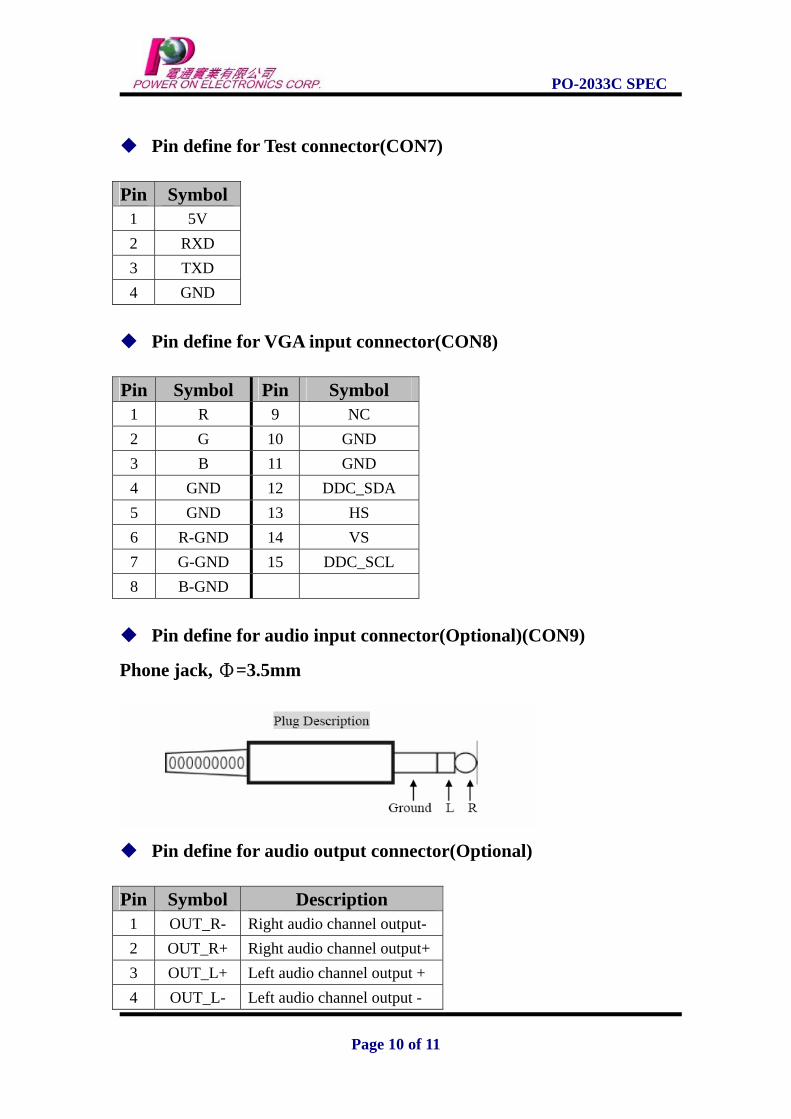
Pin define for audio input connector(Optional)(CON9)
Phone jack, Φ=3.5mm
Pin define for audio output connector(Optional)
Pin Symbol Description
1 OUT_R- Right audio channel output- 2 OUT_R+ Right audio channel output+ 3 OUT_L+ Left audio channel output + 4 OUT_L- Left audio channel output -
Page 10 of 11
PO-2033C SPEC
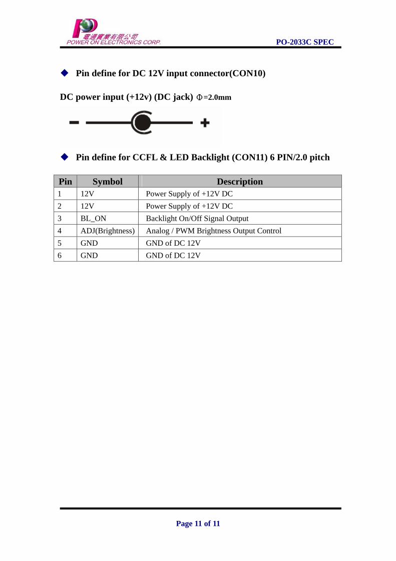
Pin define for DC 12V input connector(CON10) DC power input (+12v) (DC jack) Φ=2.0mm
Pin define for CCFL & LED Backlight (CON11) 6 PIN/2.0 pitch
Pin Symbol Description 1 12V Power Supply of +12V DC 2 12V Power Supply of +12V DC 3 BL_ON Backlight On/Off Signal Output 4 ADJ(Brightness) Analog / PWM Brightness Output Control 5 GND GND of DC 12V 6 GND GND of DC 12V
Page 11 of 11