
Pngrb Gsr808(e)
50
PETROLEUM AND NATURAL GAS REGULATORY BOARD NOTIFICATION New Delhi, the 11 th November, 2009 G.S.R. 808(E).-In exercise of the powers conferred by section 61 of the Petroleum and Natural Gas Regulatory Act, 2006 (19 of 2006), the Petroleum and Natural Gas Regulatory Board hereby makes the following regulations, namely:- 1. Short title and commencement. (1) These regulations may be called the Petroleum and Natural Gas Regulatory Board (Technical Standards and Specifications including Safety Standards for Natural Gas Pipelines) Regulations, 2009. (2) They shall come into force on the date of their publication in the Official Gazette. 2. Definitions. (3) In these regulations, unless the context otherwise requires, (a) “Act” means the Petroleum and Natural Gas Regulatory Board Act, 2006; (b) “active regulator” means a regulator in Pressure Regulating Station (PRS) that normally controls the outlet pressure; (c) “active and monitor regulator system” means an arrangement of two regulating devices in series, one (Active) normally to control the outlet pressure and the other (Monitor) to assume control in the event of failure of the active regulator; (d) “ASME B 31.8” means standard covering Gas Transmission and Distribution Piping System referred to in Annexure VI. (e) “Board” means the Petroleum and Natural Gas Regulatory Board established under sub-section (1) of section 3 of the Act; (f) “city gas distribution entity” means an entity authorised by the Board to lay, build, operate or expand the city or local natural gas distribution network; (g) “compressor station” means an installation on the pipeline having compressor units to boost gas pressure; (h) “creep relief valve” means a relief valve installed to relieve over pressure caused by creep in the system and having maximum 1 % flow capacity of such a system; (i) “intermediate pigging station ” means an installation having facility for receiving and launching of pigs for pigging operations; (j) “onshore” means areas other than offshore which shall form the scope of these standards. Feeder lines from jetty or other storage points shall also form a part of 1
Transcript of Pngrb Gsr808(e)

PETROLEUM AND NATURAL GAS REGULATORY BOARD
NOTIFICATION
New Delhi, the 11th November, 2009
G.S.R. 808(E).-In exercise of the powers conferred by section 61 of the Petroleum and Natural Gas Regulatory Act, 2006 (19 of 2006), the Petroleum and Natural Gas Regulatory Board hereby makes the following regulations, namely:-
1. Short title and commencement.
(1) These regulations may be called the Petroleum and Natural Gas Regulatory Board (Technical Standards and Specifications including Safety Standards for Natural Gas Pipelines) Regulations, 2009.
(2) They shall come into force on the date of their publication in the Official Gazette.
2. Definitions.
(3) In these regulations, unless the context otherwise requires,
(a) “Act” means the Petroleum and Natural Gas Regulatory Board Act, 2006;
(b) “active regulator” means a regulator in Pressure Regulating Station (PRS) that normally controls the outlet pressure;
(c) “active and monitor regulator system” means an arrangement of two regulating devices in series, one (Active) normally to control the outlet pressure and the other (Monitor) to assume control in the event of failure of the active regulator;
(d) “ASME B 31.8” means standard covering Gas Transmission and Distribution Piping System referred to in Annexure VI.
(e) “Board” means the Petroleum and Natural Gas Regulatory Board established under sub-section (1) of section 3 of the Act;
(f) “city gas distribution entity” means an entity authorised by the Board to lay, build, operate or expand the city or local natural gas distribution network;
(g) “compressor station” means an installation on the pipeline having compressor units to boost gas pressure;
(h) “creep relief valve” means a relief valve installed to relieve over pressure caused by creep in the system and having maximum 1 % flow capacity of such a system;
(i) “intermediate pigging station ” means an installation having facility for receiving and launching of pigs for pigging operations;
(j) “onshore” means areas other than offshore which shall form the scope of these standards. Feeder lines from jetty or other storage points shall also form a part of
1

the onshore pipelines. The offshore and onshore coverage as per this standard is depicted at Annexure- I;
(k) “operating company or operator” means an entity engaged in the operation of natural gas pipeline network with the authorization of the Board;
(l) “owner” means an entity that owns the natural gas pipeline network and has been authorized by the Board;
(m) “natural gas pipeline” means any pipeline including spur lines for transport of natural gas and includes all connected equipments and facilities, such as, compressors, storage facilities, metering units, etc. and gas pipelines for offshore and onshore coverage depicted at Annexure I but excludes-
(i) dedicated pipeline laid to transport natural gas to a specific customer to meet his requirement and not for resale;
(ii) pipelines in a city or local natural gas distribution network which are regulated by the Petroleum and Natural Gas Regulatory Board (Authorizing Entities to Lay, Build, Operate or Expand City or Local Natural Gas Distribution Networks) Regulations, 2008;
(n) “positive isolation” means the isolation with blind or spectacle blind in case of flanged joints or with welding the cap in case of welded joints;
(o) “right of user or right -of -way” means the area or portion of land within which the pipeline operator or owner has acquired the right through the Petroleum and Minerals Pipelines Act,1962 or in accordance with the agreement with the land owner or agency having jurisdiction over the land to lay and operate the natural gas pipelines;
(p) “slam shut valve” means a valve that is designed to close quickly in the event of an abnormal pressure (whether excess or low) being detected at a selected point in a gas pipeline system;
(q) “sub transmission pipeline” means a high pressure pipeline connecting the main natural gas pipeline to the city gate station but is owned by the CGD entity;
(r) “transmission system” means one or more segments of pipeline usually interconnected to form a network that transports gas from a gathering system, the outlet of a gas processing plant or a storage field to a high, medium or low-pressure pipeline system, a large-volume customer or another storage field;
(4) Words and expressions used and not defined in these regulations, but defined in the Act or in the rules or regulations made thereunder, shall have the meanings respectively assigned to them in the Act or in the rules or regulations, as the case may be.
3. Application.
(1) These regulations shall apply to all the entities authorised by the Board to lay, build, operate or expand natural gas pipelines under the Petroleum and Natural Gas Regulatory Board (Authorizing Entities to Lay, Build, Operate or Expand Natural Gas Pipelines) Regulations, 2008 and any other natural gas pipeline including dedicated pipelines notified by the Board from time to time.
2

(2) Definitions of design, material and equipment, welding, fabrication, installation, testing, commissioning, operation and maintenance and corrosion control of natural gas pipeline network shall be in accordance with the requirements of ASME B31.8 except in so far as such requirements are specifically cancelled, replaced or modified by the requirements specified in these regulations.
4. Scope.
(1) Requirements of these regulations shall apply to all existing and new natural gas pipelines including dedicated pipelines.
(2) These regulations shall cover pipeline design, materials and equipment, welding, fabrication, installation, testing, commissioning, operation and maintenance and corrosion control of common carrier or contract carrier natural gas pipelines (Transmission or Sub transmission) including safety requirements for natural gas pipelines. The pipelines coverage shall be as per Annexure I and includes dedicated pipelines for specific consumers.
5. Intent.
These standards are intended to ensure uniform application of design principles and to guide in selection and application of materials and components, equipment and systems and uniform operation and maintenance of the natural gas pipeline system and shall primarily focus on safety aspects of the employees and public and facilities associated with natural gas pipelines.
6. The standard.
Technical Standards and Specifications including Safety Standards (hereinafter referred to as standard) for natural gas pipelines are at Schedule I which cover Material and Equipment (Schedule 1A), Welding (Schedule 1B), Piping System Components and Fabrication (Schedule 1C), Design, Installation and Testing (Schedule 1D), Operating and Maintenance Procedures (Schedule 1E), Corrosion Control (Schedule 1F), Miscellaneous (Schedule 1G) as read with Annexure I to Annexure VI.
7. Compliance to these regulations.
(1) The Board shall monitor the compliance to these regulations either directly or through an accredited third party as per separate regulations on third party conformity assessment.
(2) If an entity has laid, built, constructed or expanded the natural gas pipeline network based on some other standard or is not meeting the requirements specified in these regulations, the entity shall carry out a detailed technical audit of its infrastructure through a Board authorized or approved third party agency. The entity thereafter shall submit the compliance report prepared by the third party along-with its time-bound mitigation plan and implementation schedule to the Board for authorization within six months from the date of notification of these regulations.
(3) The continuation of operation of existing natural gas pipeline network shall be allowed only if it meets the following requirements, namely:-
3

(i) The natural gas pipeline system shall have been tested initially at the time of commissioning in accordance with ASME B 31.8. The entity should have proper records of the same. Such test record shall have been valid for the current operation. Alternatively, if such a record is not available, the entity should produce in service test record of the natural gas pipeline network having been tested as per ASME B 31.8;
(ii) The natural gas pipeline system has leak detection system in position compressor station, gas receiving and terminal station and is operative;
(iii) There shall be protection of the system against third party damages:
Provided that-
(a) the entity shall submit self-certification in support of meeting the above requirements within a month of notification of these regulations;
(b) certifications referred to in para (a) shall be done for natural gas pipeline in construction and commissioning, operation and maintenance. The self certification shall be submitted to the Board with mitigation plan and implementation schedule;
(c) the critical components of the system as identified by the Board for such existing networks shall be complied with these regulations within a period specified at Appendix I and the authorized entity shall maintain the integrity of the existing natural gas pipeline system at all times; and
(d) provisions of these regulations related to operation and maintenance procedures shall also be applicable to all such existing installations.
8. Default and consequences.
(1) There shall be a system for ensuring compliance to the provision of these regulations through conduct of technical and safety audits during the construction, commissioning and operation phase, as well as on an on-going basis as may be specified from time to time.
(2) In the event of any default in sub regulation (1), the entity shall qualify as defaulting entity under the regulation 16(1) the of Petroleum and Natural Gas Regulatory Board (Authorizing Entities to Lay, Build, Operate or Expand Natural Gas Pipelines), Regulations, 2008.
(3) In case of any deviation or shortfall including any of the following defaults, the entity shall be given time limit for rectification of such deviation, shortfall, default and in case of non-compliance, the entity shall be liable for termination of operation or termination of authorization apart from any penal action under the provisions of the Act, namely:-
(a) if an entity fails to comply within the specified time limit of critical activities at Appendix I.
4
(b) the entity defaults three times under sub-regulation (1) of regulation 16 of the Petroleum and Natural Gas Regulatory Board (Authorizing Entities to Lay, Build, Operate or Expand Natural Gas Pipelines), Regulations, 2008.
(c) the entity is found operating the pipelines beyond the maximum allowable operating pressure (MAOP) conditions (either the original or de-rated pressure).
(d) the entity is found operating the pipeline system without conducting the hydro test as mentioned in these regulations;
(e) in the event of installations is found unsafe to be operated as per the third party periodic inspection assessment and compliance is not achieved within the notice period by the Board.
9. Requirements under other statutes.
It shall be necessary to comply with all statutory rules, regulations and Acts in force as applicable and requisite approvals shall be obtained from the relevant competent authorities for the natural gas pipeline system.
10. Miscellaneous.
(1) If any dispute arises with regards to the interpretation of any of the provisions of these regulations, the decision of the Board shall be final.
(2) The Board may at any time effect appropriate modifications in these regulations.
5

APPENDIX-ILIST OF CRITICAL ACTIVITIES
inNatural Gas Pipelines
*******
Sr. No.
Critical Infrastructure/ Activity/ Processes
Time period for implementation
Implementation plan
1
Test record for radiography, ultrasonic test or other applicable NDT methods (as carried out before commissioning)
6 monthscan be submitted in stages within 6 months
2Hydro-test (as carried out before commissioning)Report
6 monthscan be submitted in stages within 6 months
3 Pipeline cathodic protection record 6 monthscan be submitted in stages within 6 months
4 Pipeline As-built records 6 monthscan be submitted in stages within 6 months
5
Intelligent pigging shall be carried out to detect metal loss for the pipelines of size NPS of 12 inches and above and length of 10 Km and above.
2 years
If the pigging has not been done for more than 5 years for sour gas and 10 years for sweet gas pipeline, then the intelligent pigging shall be carried out within two years, otherwise relevant records shall be submitted.
6HSE Management System (including fire protection system)
6 months To be implemented
7Height of the vent shall be minimum 3 meters above working level
6 months Increase height of vent
8Gas detectors shall be installed at compressor station, gas receiving and delivery terminals
1year
Install gas detectors for SCADA backed up system, elsewhere hand held gas detector shall be provided
9Environmental friendly fire extinguishing flooding system for closed space.
2 years
For control room, switch gear and battery room, etc. (CO2 is acceptable only for unmanned station)
10HAZOP shall be done for all the pipeline facilities
1 yearHAZOP report to be submitted along with mitigation plan
6

Schedule I
Technical Standards and Specifications including Safety Standardsfor
Natural Gas Pipelines
Schedule-1A MATERIAL AND EQUIPMENT
Schedule-1B WELDING
Schedule-1C PIPING SYSTEM COMPONENTS AND FABRICATION DETAILS
Schedule-1D DESIGN, INSTALLATION AND TESTING
Schedule-1E OPERATING AND MAINTENANCE PROCEDURES
Schedule-1F CORROSION CONTROL
Schedule-1G MISCELLANEOUS
7

Schedule 1A
MATERIALS AND EQUIPMENT
MATERIALS AND EQUIPMENTS
All materials and equipments forming a permanent part of any piping system constructed according to this standard shall comply with the design and service requirements and shall be suitable for the intended fabrication or construction methods. For sour gas service requirements as per Schedule 1G shall be complied with.
MATERIALS FOR USE IN COLD CLIMATES
Materials to be used in facilities exposed to low ambient or low operating temperatures shall have adequate impact properties to prevent brittle fracture at such low temperatures.
MATERIAL SPECIFICATIONS
In addition to standards and specification covered in ASME B31.8, standards and specifications listed in Annexure II shall also be acceptable for manufacturing of various piping components forming part of the natural gas pipelines and associated facilities.
Steel Pipe
Carbon steel line pipe as per Line Pipe Specification API 5L, shall be Seamless, Electric Arc Welded (EAW) or Longitudinal / Helical Submerged Arc Welded (LSAW/HSAW) conforming to Product Specification Level (PSL 2).
Electric welded pipes manufactures to API Specification 5L shall also meet additional requirements specified under Annexure III of this standard
Carbon Equivalent
Maximum limits on Carbon Equivalent (CE) for steel line pipes shall be as follows:
For pipes having Carbon Content > 0.12%
CE(IIW) = C + Mn + Cr+Mo+V + Ni+Cu 6 5 15CE (IIW) value shall be ≤ 0.43%.
For pipes having Carbon Content ≤ 0.12%
CE(Pcm) =C + Si + Mn + Cu + Ni + Cr + Mo + V + 5B 30 20 20 60 20 15 10
CE (Pcm) value shall be ≤ 0.25%.
Mill Hydro Test
Line pipes should be hydrostatically tested in pipe mill using test pressure that produces a hoop stress equal to 95% of SMYS irrespective of material grade. For new pipeline, the test pressure shall be held for a minimum period of 15 sec.
Notch Toughness
For steel pipes of size NPS 2 and above, notch toughness shall be specified.
Ductile Iron Pipe
Use of ductile iron pipes is not permitted for natural gas pipelines.
EQUIPMENT SPECIFICATIONS
Equipment used in natural gas pipelines manufactured to standards listed in Annexure II of this standard shall also be acceptable.
8

Schedule 1B
WELDING
PREPARATION FOR WELDING
Butt WeldsNotches or laminations on pipe ends are not permitted and must be removed by cutting the pipe as a cylinder and re-beveling of pipe end or by grinding prior to welding.
Re-beveled ends shall be re-examined by Ultrasonic or magnetic particle methods if cut section is more than previously examined length.
Seal Welds
As far as practical seal welding of threaded joints should be avoided.
QUALIFICATION OF PROCEDURES AND WELDERS
Requirements for Piping Systems Operating at Hoop Stresses of 20% or more of the Specified Minimum Yield Strength
Welding procedures and welders for welding of gas pipelines shall be qualified as per API 1104 and shall include toughness testing requirements as applicable for the material to be welded.
Welding procedures and welders, for station piping shall be qualified as per ASME Boiler and Pressure Vessel (BPV) Code Section IX or API 1104.
INSPECTION OF WELDS
Inspection and Tests for Quality Control of Welds on Piping System intended to Operate at Hoops Stress Levels of 20% or
more of the Specified Minimum Yield Strength
All Non Destructive Testing (NDT) including radiographic examination shall be performed in accordance with the requirements of API 1104 except that no root crack shall be permitted.
Regardless of operating hoop stress as well as location class all carbon steel butt welds in natural gas pipelines shall be subjected to 100% radiographic examination and / or ultrasonic testing, The weld joints in vent and drain piping open to atmospheric pressure need not be radiographed/ ultrasonically tested. Such welds however shall be visually examined and root pass of at least 10% of such welds shall be examined by Liquid Penetrant Tesing.
All butt welded golden joints (i.e. welds joints which are not subjected to pressure testing, shall be subjected to 100% radiography as well as examination by ultrasonic techniques. Socket welded golden joins shall be tested by using Liquid Penetrant Inspection (LPI) method or wet Magnetic Particle Inspection (MPI) method
REPAIR OR REMOVAL OF DEFECTIVE WELDS IN PIPING INTENDED TO OPERATE AT HOOP STRESS LEVELS OF 20% OR MORE OF THE SPECIFIED MINIMUM YIELD STRENGTH
Welds having defects shall be removed or repaired in accordance with API 1104.
Repaired weld areas shall be subjected to additional radiography or ultrasonic testing after repair.


Schedule 1C
PIPING SYSTEM COMPONENTS AND FABRICATION DETAILS
PIPING SYSTEM COMPONENTS AND FABRICATION DETAILS
General
In addition to standards and specifications covered under ASME B 31.8 for various piping components, piping components manufactured conforming to standards and specifications listed under Annexure II of this standard shall be acceptable.
Valves and Pressure Reducing Devices
Valves having pressure containing components including body, bonnet, cover, end flanges etc. made of cast iron or ductile iron shall not be used
Flanges
Flanges made of cast iron, ductile iron and non-ferrous materials (brass or bronze) shall not be used.
Flanges and flanged components shall not be used in buried piping unless entire flange assembly is encapsulated in water tight and electrically insulating materials
Bolting
All stud bolts and nuts used in natural gas pipelines shall meet the design conditions as per applicable ASTM standards. Cast iron, brass or bronze materials are not permitted.
Fittings other than Valves and Flanges
Fittings made of cast iron and ductile iron shall not be used.
Gaskets
Plain and compressed asbestos gaskets shall not be used.

Schedule 1D
DESIGN, INSTALLATION AND TESTING
DESIGN INSTALLATION AND TESTING
General Provisions
The selection of design for natural gas pipelines shall be based on the gas properties, required flow rate operating pressure and the environmental conditions.
All components of the pipeline shall be designed to be suitable and fit for purpose throughout the design life.
Cross country pipeline of size less than NPS 4 shall not be used.
Other design Requirements
Necessary calculations shall be carried out to verify structural integrity and stability of the pipeline for the combined effect of pressure, temperature, bending, soil/pipe interaction, external loads and other environmental parameters as applicable, during all phases of work from installation to operation. Such calculations shall include but not limited to the following:
- Buoyancy control and stability analysis for pipeline section to be installed in areas subjected to flooding / submergence,
- Crossing analysis of major rivers. - Evaluation of potential for earthquake
occurrence along pipeline route and carrying out requisite seismic analysis to ensure safety and integrity of the pipeline system.
Buildings Intended for Human Occupancy and Location Classes for Design and Construction
For the purpose of determining number of buildings for human occupancy and
Location Class, 1 - mile distance shall be replaced by 1600 m and fractions thereof.
When a cluster of buildings intended for human occupancy, indicates that a basic mile (1600m) of pipeline should be identified as location class 2 or location class 3, may be terminated 200 m from the nearest building in the cluster on either side (i.e. at start of cluster and at end of cluster).
The boundary between location class 1 and location class 2 or location class 3 shall be at least 200m away from the building closest to the boundary.
STEEL PIPE
Additional Requirement for Nominal Wall Thickness
Consideration shall also be given to loading due to following while selecting nominal wall thickness t as per ASME B31.8 as appropriate:- Overburden loads- Dynamic and seismic loads- Cyclic and vibratory loads - Internal pressure fluctuations- Geo-technical loads (including slides,
differential settlement of piping, loss of support, and thermal effect of the pipeline on soil properties).
Design Factors (f) and Location Classes All exceptions to basic design factors to be used in design formula shall be as per Table 1 given herein this standard.
The minimum wall thickness for cross country pipelines of size NPS 4” and above shall be 6.4 mm.
Pipelines or Mains on Bridges

Pipelines on railroad and vehicular bridges should be avoided. Pipeline installed on
dedicated bridges shall be designed with design factor as indicated in Table 1.
Table 1 - Design Factors for Steel Pipe Construction
Notes:
(1) Higher thickness may be used if required to control stresses or stability during installation and operation.
(2) Wherever, Table 841.114B is referred in ASME B31.8 it shall be read as per Table 1 of this standard.
Facility Location Class1 2 3 4
Pipelines [Also See para. 840.21(b) of ASME B31.8]
0.72 0.60 0.50 0.40
Crossings of roads, without casing:(a) Private roads(a) Unimproved public roads(b) Roads, highways, or public streets,
with hard surface
0.720.600.60
0.600.600.50
0..500.500.50
0.400.400.40
Crossings of roads, with casing:(a) Private roads(b) Unimproved public roads (c) Roads, highways, or public streets,
with hard surface and Railway crossings
0.720.720.72
0.600.600.60
0.500.500.50
0.400.400.40
Pipelines on bridges 0.60 0.60 0.50 0.40
Parallel Encroachment of pipeline on roads and railways(a) Private roads(b) Unimproved public roads (c) Roads, highways, or public streets,
with hard surface and Railway crossings
0.720.720.60
0.600.600.60
0.500.500.50
0.400.400.40
River Crossing- open cut [1]0.72 0.60 0.50 0.40
Horizontal Direction Drilling (HDD) [1] 0.72 0.60 0.50 0.40Compressor station piping 0.50 0.50 0.50 0.40Fabricated assemblies (scraper traps, SV stations, pressure/flow control and metering facilities, etc.) [Also See para. 841.121 of ASME B31.8]
0.60 0.60 0.50 0.40
Near concentration of people in Location Classes 1 and 2 [2] 0.50 0.50 0.50 0.40

LOCATON AND LAYOUT OF PIPELINE INSTALLATIONS
• Location
Originating, intermediate and terminal facilities of pipeline such as Originating Compressor Station / Originating Station, Intermediate Compressor Station, Intermediate Pigging Station, Tap-off Station, Metering and Regulating Stations and Sectionalizing Valve Stations etc. should be located considering following aspects:
I. Functional and pipeline hydraulic requirements.
II. Environmental consideration based on Environmental Impact Assessment (EIA) and Risk Assessment (RA) study for the pipeline and stations.
III. The HAZOP and risk analysis. IV. The availability of space for
future augmentation of facilities.V. Approachability, water table and
flood level and natural drainage.
In addition to above, compressor station should be located at such clear distances from adjacent property not under control of the pipeline owner / operator so as to minimize the hazard of communication of fire to the compressor station from structures on adjacent property.
• Equipment Layout
Following aspects be considered while establishing station layout.
I. Station equipment and their sizesII. Utility requirement.
III. Flaring / cold venting requirements.
IV. Operation and maintenance philosophy of station equipment.
V. Requirement of space and access around the compressor shed / house
and other equipment VI. High Tension (HT) pole
structure, Transformers, Breakers and Motor Control Centre (MCC) etc shall be e located in non hazardous area.
VII. Over Head power lines shall not be allowed to pass directly above the process piping/equipment area and buildings.
Minimum Inter-distances between various station facilities and utilities shall be as per Annexure IV.
• Piping Layout
Station piping may be installed above ground or buried. Buried piping inside the terminal area should have a minimum cover of 1.0 m from top of pipe to finished ground level.
At internal storm water drains a minimum cover of 300 mm with additional concrete slab extending at least 500 mm on either side of pipe edge shall be provided.
Where buried pipes come above ground, the anti-corrosion coating on the buried pipe will continue for a length of at least 300 mm above ground.
Platforms and crossovers shall be provided for ease of operation and maintenance of above ground piping where required
All the above ground piping should be properly supported to withstand operational safety requirements.
PROTECTION OF FACILITIES
Properly laid out roads around various facilities shall be provided within the installation area for smooth access of fire tenders etc. in case of emergency.

Proper industry type boundary masonry wall at least three (3) mtrs high including 0.6 mtrs barbed wire on top shall be provided all around the major installation such as dispatch station, compressor station, Sectionalizing Valve (SV) station and delivery stations in line with MHA ( Ministry of Home Affairs) guidelines. For other installations 3.0 m high chain link fencing including 0.6 m barbed wire on top can also be provided.
Emergency exit with proper gate shall be provided in the earmarked zone at all compressor stations.Pipeline system should be equipped with following:
a. Supervisory Control and Data Acquisition (SCADA) System.b. Leak detection system with provision for identification / location of leak and isolation of affected section.c. Communication facilities d. Emergency Response and Disaster Management Plan (ERDMP)
SCADA & TELECOM REQUIREMENTS
Gas pipeline system should be monitored and controlled using SCADA or equivalent monitoring and control system to ensure effective and reliable control, management and supervision of the pipeline.
Compressor Stations, Intermediate Pigging Stations, Dispatch and Receiving Stations, Sectionalizing Valve stations with remote operation capabilities as well as Telecom Repeater Stations including voice communication facilities/ Cathodic Protection Stations (in case located independent of other facilities) should have suitable field signals’ connectivity with the control system. Application software modules / functions
should be based on the requirement of pipeline operating company.
Provision shall be made for transmitting the Pressure, Temperature, Flow measurement & gas composition data etc. through SCADA system to Central Gas Management Systems (as and when it is established) pertaining to gas entry , gas exit and compressor stations. Board shall allow a suitable time period to the entities for implementation of this system
PIPELINE SYSTEM AND COMPONENT
Utility Piping
All utility piping at Station shall comply with the requirement of ASME B31.3.
• Valves
Valves shall be provided for isolating sections of pipeline / station piping in order to:
a) Limit the hazard and damage from accidental discharge from pipeline/ piping;
b) Facilitate repair and maintenance of pipeline / piping facilities and critical equipments.
Stations Block valves with remote shut off provision from the control room shall be provided at the inlet and outlet of the compressor station piping to isolate the pipeline from compressor station facilities in case of emergency at compressor station
Mainline /Sectionalizing valves shall be installed on the pipeline for the operation and maintenance and control of emergencies. Spacing between mainline valves / sectionalizing valve in various Location Classes shall not exceed values given in Table 2.

Table 2
Overhead power lines shall not be allowed to cross directly over the process area of the valve station facilities.
The provisions of remote operation should be as per the operation and control philosophy adopted for the pipeline by the owner/operating company.
Mainline /Sectionalizing valve should preferably be installed below ground and be provided with suitable stem extension for ease of operation.
Sectionalizing block valve in the piggable section of pipeline shall be full bore type to allow safe passage of pigs. The bore size shall conform to API 6D / ISO-14313.
Actuator for the actuated valves may be selected based on type of valve, availability of power and project philosophy preferably operating on the fluid in the pipeline system.
As far as practical, all mainline isolation valves should be with butt weld ends. Flanged end valves shall not be used in buried piping except at the locations where hot tapping operation is to be carried out for which, buried valve with flanged ends may be used to facilitate mounting of hot tapping machine.
Valve surface shall be applied with suitable corrosion protection coating.
Sectionalizing Valve (s) station shall have blow down or vent line connection to evacuate the isolated pipeline section in case of an emergency and / or repair. The size of the connections for blowing down the mainline line shall be not be less than 1/3rd
of the mainline size.
All joints between the mainline pipe and the first valve on the branch, including the inlet to first valve, should be welded joint in order to restrict possible leakage which cannot be isolated by the closure of the valve.
• Pigging Facilities
Main gas pipelines and feeder lines, spur lines and branch lines of 4” and above size and length greater than 10 km shall be provided with pigging facilities.
Spacing between consecutive pigging stations shall be determined based on the diameter of pipeline, nature of pigging operation and capability of the pigs. Spacing in excess of 200 km shall be avoided.
Pigging stations shall be provided with all weather access road from the nearest road
• Bends
The minimum radius of Cold Field Bend shall be as per Table 3.
Use of Mitre bends shall not be permitted.
Table 3
Where ‘D ‘ is outside diameter of steel pipe.
The minimum bend radius for hot bends
Location ClassMaximum
Distance in Kms
1 322 243 164 8
Nominal Pipe Size (inch)
Minimum Bend Radius
12 and below 21D14 to 16 30 D
18 and above 40 D
shall be 3D.
• Insulating Joints
Insulating joints shall be provided to electrically isolate the buried pipeline from the above ground pipeline and station piping
• Branch Connections
Branch connections of size below NPS 2 are not recommended in buried pipeline section.
All branch connections from mainline shall be provided with an isolation valve located at a minimum possible distance from the main pipeline.
Where welded or forged branch connections are installed in the pipelines designed for pigging, special branch connections should be used to ensure that the pig is not damaged while passing the connection.
Flow tees or guided bar tees should be used to ensure smooth passage of pigs.
• Flanged or Threaded joints, Bolts, Nuts, Gasket and other Fittings
Threaded joints shall not be used in underground sections of cross country pipelines. Threaded joints may be permitted in above-ground stations / above ground section of SV stations, only if a welded isolation valve is provided before it.
The flanged joint shall be made using either spiral wound metallic gaskets or metallic ring type gaskets. Plain asbestos sheet / reinforced gaskets / CAF gaskets shall not be used.
• Metering Facilities
Appropriate type of meters shall be installed at all custody transfer points meeting requirements of American Gas Association (AGA) standard as agreed mutually between buyer and seller. Dry gas filters may be installed at the upstream of the meters if
required by the manufacturer of meters
• Electrical Installations of Pipeline Stations
Area Classification of Pipeline Installation, as basis for Selection of Electrical Equipment for Natural Gas Pipeline Station, shall follow IS-5572. The specification of Electrical equipments shall be in line with IS :- 5571, “Guide for selection of Electrical Equipment for Hazardous Area”.. Fire protection in Electrical installations shall be designed as per relevant IS standard as enclosed in Annexure II.
All electrical equipment, systems, structures and fencing, etc. shall be suitably earthed in accordance with IS 3043.
The earthing system shall have an earthing network grid with required number of electrodes. All Electrical equipment operating above 250 volts shall have two separate and distinct connections to earth grids. Separate earthing grid shall be provided for instrument and electrical power.
Lightening protection shall be provided as per the requirements of IS:2309. Self conducting structures having metal thickness of more than 4.8 mm may not require lightning protection with aerial rod and down conductors. They shall, however, be connected to the earthing system, at least, at two points at the base in line with relevant IS standard as enclosed in Annexure II.
• Instrumentation and Control System
Instrumentation and control system for the Pipeline system shall in general meet the requirement of API Standard API-RP-551 to API-RP-556 "Manual on Installation of Refinery Instruments and Control Systems.
• Communication

A reliable and dedicated communications system to interact between various stations including sectionalizing valve station, with remote operation capability, along the entire pipeline shall be designed, installed and maintained to ensure safe operations under both normal and emergency situations.
• Compressor Station
The compressor station(s) shall be designed in accordance with the requirements of ASME B31.8.
Typical facilities at a typical gas compressors stations is enclosed at Annexure- IV and shall consist of following:
Compressor
Centrifugal type process gas compressors shall be designed in accordance with API-617. Other Compressors shall be designed in accordance with API-618. For small size compressors, API-11P may also be considered
Compressor station for National Gas Grid shall have provision for reverse flow.
Gas after Coolers
Coolers may be installed to bring down the compressed gas temperature to desired level for maintaining coating integrity of the main pipeline before it is introduced in the downstream pipeline.
Station Bye Pass: Compressor station shall have a bye pass to facilitate flow of gas in to next section of the pipeline in the event of isolation of the compressor station for any reason.
• Other requirements
All gas compressor units shall be equipped with shutdown or alarm devices to operate in the event of inadequate cooling or lubrication of the units.
All compressor buildings or Compressors skids shall have fixed gas detectors to detect leakage of gas inside the unit and generate alarm and trip signals for the unit in case the gas concentration in air is more than 20% of lower explosive limit.
Fire & gas detectors shall be installed in the compressor buildings or compressors skids to initiate shut down of the unit, isolation of the compartment and release of clean agent / CO2 inside the unit in the event of occurrence of fire. In addition, compressor and compressor driver (Engine/Turbine/ motors skids) should be equipped with vibration monitoring devices with provisions for local and / or remote alarm shut down capabilities.
Environment friendly Flooding fire extinguishing system shall only be used either as an existing installation or when there is no manning the enclosure.
Flooding system for CO2 / clean agent shall be applicable only in case of enclosed compressor area,
Smoke detectors shall be installed in the control room of compressor station building, and cable trenches in electrical sub -station to initiate alarm in case of detection of smoke.
Conventional break glass type fire alarm system shall be installed at all strategic locations of the stations.
SAFETY DEVICES AND FEATURES
The safety system for compression facilities

and gas transportation system shall consist of following:
• Emergency Shutdown System
Compressor station shall be provided with an emergency shutdown system (ESD) for reliably and safely shutting down the station facilities in case of emergency and for venting out of gas when situation demands so. The ESD system shall have provision of shutdown all gas compressing equipments, all gas fired equipment, and shall de-energize the electrical facilities located in the vicinity of gas headers and in the compressor shed, except those that provide emergency lighting and those that are necessary for protection of the equipment.
Emergency shutdown system shall be operable from at least 2 locations away from the gas area of the station out of which one should be located in the field out side the compressor building.
• Pressure Limiting Devices
Over pressure shut off valves shall be provided upstream of pressure controlling system/regulators along with alarm provision in case of failure of the pressure control system / regulators.
Pipe size shall be such that gas velocities in the piping shall not be more than 20 mtr/sec for unfiltered gas and 40 mtr/sec for filtered gas at peak condition. Sound pressure level shall be the maximum limit prescribed by environment dept / pollution control board.
Any equipment or section of the pipeline containing Natural Gas in the form of trapped volume shall be protected against excessive pressure developed due to rise in surrounding temperature by installing suitable safety relief valves. The discharge of the safety relief valves shall be connected to vent line system. All such safety relief valves shall have lock open type isolation
valve upstream of relief valve. In addition lock open isolation valve downstream of relief valve shall be provided if vent is connected to flare header.
Pressure safety valves of sufficient capacity and sensitivity or other safety devices / system shall be installed to ensure that the normal operating pressure of the system does not exceeded by more than 10%, of the Maximum Allowable Operating Pressure (MAOP).
• Vent Lines
Vent line shall be designed and installed to vent out the gas from relief valves, if provided, to atmosphere. Blow down piping connected to vent line should extend to location where the discharge of gas shall not create a hazard to the compressor station or the surrounding area.
The discharge from safety valve shall be vented vertically upwards to atmosphere at an elevation of 3 meter (minimum) above working level or the tallest structure within a radius of 15 meters which ever is higher ( Only in case of Compressor station) for effective dispersion of hydrocarbons. In this case, isolation valves on down stream of safety valve are not required. Isolation valve shall be provided downstream of safety valve if the safety valve discharge line is connected to flare header.
INSTALLATION AND CONSTRUCTION
Pipeline shall be buried below ground level and unless construction above ground is found to be desirable for exceptional reasons.
• Pipeline Cover
Gas pipelines shall be buried with a minimum cover as specified in Table 4
In rocky areas and areas with hard soils /

gravels, minimum 150 mm thick padding of soft soil / sand shall be provided all around the pipe. If required protective layer of rock-shield / rock guard or concrete coating may be provided to prevent damage to coating / steel pipe during installation and testing in place of soft padding,
No dwellings or construction in any form shall be permitted within RoU.
• Excavation
In cultivable land and other specifically designated areas, the top 300mm soil excavated from the trench shall be stored separately. This top soil shall be replaced in original position after backfilling and compacting of the rest of the trench.
The width of trench shall be such that a minimum clear distance of 200mm for trench in normal soil and 300mm for trench in rock is maintained between edge of pipe and the trench wall at the bottom of the trench.
TABLE 4 - MINIMUM COVER REQUIREMENTS
FOR PIPELINES
Sl No.
Locations Minimum Cover
in meters [i]
i) Normal / rocky terrain
1.0
ii) Drainage, ditches at roads / railway crossing
1.0
iii) Minor river crossings, tidal areas and other watercourses [ii]
1.5
iv) Major river crossings [ii]
2.5
v) River with rocky bed 1.5
vi) lined canals / drains / nalas etc.
1.5
vii) Cased / uncased road 1.2
crossing [iii]
viii) Cased railway crossing [iii]
1.7
NOTES:
i. Cover shall be measured from the top of coated pipe to the top of the undisturbed surface of soil or the top of graded working strip, whichever is lower. The fill material in the working strip shall not be considered in the depth of cover.
ii. For river / watercourses that are prone to scour and / or erosion, the specified cover shall be measured from the expected lowest bed profile after scouring / erosion. Where scour level is not known, an additional cover of at least 1 meter (Over and above the cover mentioned as above in the Table 4) shall be provided from the existing bed of the river/water course except in case of Rocky bed.
iii. The cover shall be measured from the top of road or top of rail, as the case may be.
iv. Whenever the above provisions of cover cannot be provided due to site constraints, additional protection in form of casing/ concreting, soil bags, etc. shall be provided.
v. When insisted by authorities, the depth shall be maintained as per the directions of the concern authorities.
The location of a new buried pipeline, when running parallel to an existing buried pipeline, should be at a minimum clear distance of 5.0 meters from the existing underground pipeline when heavy conventional construction equipment is expected to be utilized. This distance may be reduced after careful assessment of

construction methodologies so that it does not result in unsafe conditions during construction. In any case the minimum clear distance shall not be less than 3.0 meters. Existing pipeline should be clearly marked on the ground during construction. Bi-language (local language and Hindi / English) caution signs should be installed while working in such areas.
While laying more than one new pipeline in the same trench, clear separation of minimum 500mm shall be maintained between adjacent pipelines.
No pipeline should be located within 15.0 meters of any private dwelling or any industrial building or place of public assembly in which persons work, congregate or assemble, unless it is provided with at least 300 mm of cover over and above minimum cover specified in Table 4. or the other mitigation measure provided like higher pipe wall thickness / protection with RCC Slab.
• Crossing
As far as possible, pipeline should cross existing facility at right angles. Turning Points (TPs) provided on either side of crossings shall be located at sufficient distance away from RoU/RoW of existing facility to facilitate installation of bends except when the pipeline runs parallel to existing facility. Minimum cover shall be as per Table 4.
When insisted by authorities, road / highway / rail crossing is installed using a casing pipe, minimum diameter, thickness and length of casing pipe shall comply with API RP-1102. Carrier pipe shall be adequately supported inside casing pipe using casing insulators made of durable and electrically non-conductive materials to ensure no contact between carrier and casing pipe. Casing end seals shall be installed to prevent ingress of water and / or foreign material into casing in case the
carrier pipe is protected with zinc ribbon anodes. Vent and drains shall be provided on near ends of the casing pipe. If required, the carrier pipes outside the casing pipe shall be independently supported.
When the casing pipe is being filled with bentonite there is no need to provide the end seals.
Carrier pipe / casing pipe may be installed by open cut, boring, jacking or other suitable trench less techniques.
• Crossing of Utilities
When a buried pipeline has to cross any existing underground pipeline, cable, drain or other services, the pipeline shall be laid at least 500 mm below such services. Where it is not possible to obtain the above mentioned clearance, special design and construction shall be used. The existing pipeline shall be properly supported during and after the construction activities.
When laid parallel to any existing underground pipeline, cable, drain or other services, the underground pipeline shall be laid with a clear horizontal distance of at least 500 mm. Where it is not possible to maintain the above mentioned clearance, special design and construction shall be used.
A clearance sufficiently large to avoid electrical fault current interference shall be maintained between the pipeline and the grounding facilities of electrical transmission lines.
A minimum separation of 3 meter should be maintained between pipeline and transmission tower footings.
Cold field bends
The radius of cold field bends shall be as specified in Table 3.
The ends of each bend length shall be straight and not involved anyway in the bending. In no event shall the end of the bend be closer than 0.5 m or equal to pipe outside diameter, whichever is small, from the end of a pipe or within one meter of a girth weld. The ovality in each pipe after bending shall be less than 2.5 percent of the nominal diameter, at any point.
Bends shall be checked by pulling a gauging pig fitted with gauging plate of diameter equal to 95 percent of the nominal internal diameter of the pipe. The pig shall have at least two cups not less than 300mm apart or pipe nominal diameter whichever is larger.
Pipes with longitudinal welds shall be bend in such a way that weld lies in the plane passing through neutral axis of the bend.
Corrosion coating after bending shall be visually examined and holiday tested for defects. Any defects or disbonding of the coating caused during bending (including forced ridges in the coating) shall be repaired.
• Lowering
Before lowering operations are commenced, particular attention should be paid to the suitability of the trench to allow the pipeline to be lowered without damage to the coating and to give a reasonably even support to the pipeline.
All points on the pipeline where the coating has been in contact with either the skids or with the lifting equipment during the laying operation shall be carefully inspected for damages, dents or other defects. Defect, if any, shall be completely repaired.
Short completed sections of the pipeline should be cleaned with compressed air in order to remove dirt from the inside of pipe sections
Before lowering in, full circumference of the pipe shall be checked by holiday detector, set at an appropriate voltage suitable for the applied coating, to detect any holiday in the coating including field joint coating. Any coating defect or damage identified by holiday detection shall be repaired.
• Backfilling
Backfilling shall be carried out immediately to the extent possible after the pipeline has been lowered into the trench.
Excavated soil from the trench shall be used for backfilling unless the same is not suitable. The backfill material shall contain no extraneous material and / or hard lumps of soil, which could damage the pipe and / or coating or leave voids in the backfilled trench.
In cultivable land and other specifically designated areas, top soil excavated from the trench and stored separately, shall be restored to normal conditions.
Slope breakers or other measures shall be installed in trenches dug in steep areas (slope of generally 10 percent and more) to prevent erosion of the back fill. RoU should be provided with drainage ditches to allow water run-off and avoid backfill wash out.
• Pipeline Markers
Pipeline markers to indicate presence of pipeline and chainage shall be provided all along the pipeline route at a maximum spacing of 1 km. The markers shall also be provided on each side of highways (NH/SH), major district roads (MDR), railway crossings and water body crossings. At other crossings where third party activity is expected and at entrance to stations one marker shall be provided.
Markers at crossings shall display caution, words “Gas Pipeline” name of the operating
company, emergency telephone contact nos. etc. in regional / Hindi and English languages.
• Cleaning of Pipeline
Before hydro testing, the section of the pipeline shall be cleaned and checked for the geometry of the pipeline.
A gauging pig shall be passed through the pipeline to prove the internal diameter of the entire pipeline. The gauging plate shall have a diameter equal to 95% of the internal diameter of the thickest line pipe used in the pipeline. The gauging plate should preferably be made of Aluminum plate.
TESTING AFTER CONSTRUCTION
• Testing
All pipeline sections shall be hydro tested after construction except for pre-tested pipes used in tie-in spools.
No welding (other than tie-in welds) and / or mechanical handling of pipe is permitted after pressure testing.
Cased crossings (rail/road) and rivers crossing sections shall be pressure tested before and after installation for a period of at least four (4) hours. Such sections shall be retested along with completed mainline sections.
Water should be used as test medium. When required, test water may be dosed with required quantity of corrosion inhibitors and oxygen scavenger depending upon quality of the water.
API-1110 recommended practices should be used as guidance for the pressure testing of the pipeline.
• Test Pressure and Duration
Pipeline
The minimum test pressure at any point along the pipeline shall be as given in Table 5.
The maximum test pressure shall not exceed the mill test pressure or pressure required to produce a hoop stress equal to 95 percent of SMYS of the pipe material based on minimum wall thickness in the test section.
The test duration shall be maintained for a minimum twenty four (24) hours or as required by statutory authorities.
In case of any pressure drop beyond 1 bar over and above the permissible pressure drop due to temperature variation, then the total section under test shall be further subjected to 24 hours tightness test.
Mainline valves should be installed after successful pressure testing of the pipeline
Table 5: Minimum Test Pressure
Pressure variations during testing shall be acceptable, if caused by factors other than leakage, like temperature variations. Maximum unaccounted pressure variation shall not exceed 0.3 bar. Pipelines not meeting the requirements shall be repaired and retested in accordance with the requirements of these standards.
Location Class
Pressure Requirement
1 1.25 x Design Pressure2 1.25 x Design Pressure3 1.40 x Design Pressure4 1.40 x Design Pressure
Above Ground Station Piping
Pressure testing of station piping shall be carried out separately from pipeline.
Station piping shall be tested at minimum test pressure of 1.4 times the design pressure.
The test pressure shall be maintained for a minimum period of four (4) hours.
Low Pressure Leak Check
All flanged joints in above ground pipeline / piping, equipment, instrument impulse tubing, etc. shall be tested by pressurizing the piping system / equipment with dry compressed air or Nitrogen or gas at a pressure of 7.0 kg/cm2g and checked by means of soap solution / suitable digital gauge for leaks.
• Dewatering and Drying
After hydro testing of the pipeline sections / station piping, the section shall be dewatered immediately except when the section is filled with inhibitor. After dewatering, the pipeline section shall undergo swabbing and station piping should also be blown by compressed air to remove water. Further pipeline should be dried either by super dry air or vacuum drying to at least – 8 deg centigrade dew point.
Alternatively the pipeline after hydro test is depressurized to atmospheric pressure with water in place. This water column is displaced by 1 or 2 Nitrogen column of 2 to 3 km long than the dry natural gas column. Each column is separated by uni-directional pigs. The Hydrocarbon gas/ gas/ mixture receiving end to be burnt till the pipelines is dried to required level.
• Geometric Survey
Survey to establish pipeline geometry using Electronic Geometric Pigs (EGP) shall be conducted after completion and acceptance of following pipeline activities:
a. Gauging and cleaningb. Hydro testingc. Installation of Mainline /
Sectionalizing Valve stationsd. All tie-ins.e. Completion of all facilities on the
pipeline
• Pre-commissioning / Inertization
Required inertization of the station piping and pipeline shall be carried out by use of nitrogen or by vacuum drying. Care should be taken to ensure explosive mixture of gas and air in the pipeline or piping does not form. Residual oxygen content in the pipeline or piping shall be less than 2.0 percent (vol/vol).
• Preservation of Pipeline
If the pipeline commissioning after pressure testing is anticipated to be delayed beyond six (6) months, suitable preservation technique shall be adopted to prevent internal corrosion during such period.
Pipeline may be preserved using inhibited dosed with adequate quantity of corrosion inhibitors or by filling the line with any inert gas and at a positive pressure
• Commissioning
There shall be documented commissioning procedure to cover all the activities for pipeline sections under commissioning and to ensure proper communication while commissioning work.
The commissioning operation shall be controlled and supervised by authorized personnel.

The local administration and other statuary bodies what so ever applicable shall be informed and work shall be carried out under qualified safety officer.
Upon completion of the Gas-in process there shall be a commissioning report endorsed by the authorized person and the safety officer.
Before starting commissioning activities, following shall be ensured:
a. Commissioning Procedure in place
b. Pressure testing is completed for entire pipeline and associated station piping
c. Low pressure leak check of the above ground piping / flanged joints completed.
d. Pipeline has been cleaned and debris etc. removed.
e. All mainline / sectionalizing valves are installed as per requirement.
f. All Golden joints are inspected and accepted.
g. Geometric survey of pipeline section is carried out, if applicable.
h. Trained and experience personnel are available / deployed to carry out commissioning.
DOCUMENTATION
Besides the details mentioned in the ASME B31.8 clause 867, the Pipeline owner shall also maintain following records/ documents:
I. Design & Engineering documentsII. Route maps, alignment sheets,
crossings, drawings, Piping and Instrumentation Diagrams, station
layouts,III. Vendor and subcontractor assessments
and recordsIV. Inspection and maintenance reportsV. Material certification including
dimension, metallurgy, performance and functional report
VI. A complete pipe book.VII. Pressure test records include location
of leaks or failures, if any, and description of repair under taken.
VIII. As - built drawings including pipelineIX. Strength, tightness and leak test
reportsX. Complete asset of each location with
identification.XI. NDT records of welds
XII. Geometric survey reports, if applicable.
XIII. Cleaning and drying recordsXIV. Commissioning reportsXV. Non-conformance/ deviation reports
XVI. Calibration records of Inspection, Measuring & Metering and Test equipment
XVII. Audit compliance reports
XVIII. Statutory clearancesXIX. Approved drawings/documentsXX. International practicesXXI. Equipment and operations manuals.
Schedule 1E
OPERATING AND MAINTENANCE PROCEDURES
Operating and maintenance of natural gas pipelines shall be in accordance with requirements of ASME B31.8 except insofar as such requirements are specifically cancelled, replaced or amended by the requirements specified herein this standard.
OPERATING AND MAINTENANCE PROCEDURES AFFECTING THE SAFETY OF GAS TRANSMISSION AND DISTRIBUTION FACILITIES
Basic Requirements
The entity operating natural gas pipeline shall have an effective Health, Safety and Environment Management System (HSE Management System) and Management of Change System in place to ensure overall safety during operation and emergencies.
The HSE Management System shall cover the following key elements.
• HSE Policy Statement• Organizational objectives to ensure
implementation of the policy• Set of detailed processes supporting
each activities of the HSE management system.
• Implementation of control and monitoring activities
• Periodic, monitoring, review and reporting of performance
• Audit of internal and external activities
Following processes shall be prepared as part of HSE Management System:
• Emergency Management System to safely handle emergencies with
minimal risk. • Disaster Management Plan
encompassing offsite and onsite emergency response plans and mutual aid system
• Hazard Identification Processes such as HAZOP
• Risk Analysis and Risk Assessment Process such as QRA
• Safety and Technical Competency System.
• An Operational Health and Safety Legal applicability Matrix as well as Operational Health and Safety (OH&S) Legal Compliance matrix.
Essential Features of an Operating and Maintenance Plan
Besides the items recommended for inclusion in the operating and maintenance plan, mentioned in ASME B31.8, the following shall also be included in the Operating and Maintenance System:
1. Operating Philosophy and Procedures
An operating philosophy document clearly indicating the operational procedures required and the safe operating parameters shall be developed. Operating procedures, with suitable operational controls based on formal hazard identification and risk assessment, shall be developed. A documented isolation philosophy shall be prepared and provided to operational personnel. A drawing showing the orientation of the plant, location of major services, entry and emergency exits etc. at compressor station. It should also show the main components,

including their identification number.
In order to provide safe working conditions and to carry out the work safely, a work permit system shall be followed. The basic purpose of the work permit system is to ensure that work is carried out in the safest possible manner to prevent injuries to personnel, protect property from damage, avoid fire etc.
Action in the event of emergency shall be clearly established and understood by all concerned and displayed prominently. Personal Protective Equipments (PPE) shall be provided and used by all operating personnel.
Do’s and Don’ts shall be displayed at scrapper trap, Sectionalizing Valve Station, Block Valve Station, and Compressor Station area. “No Mobile phone”, “No smoking sign”, “No lighter / matches” shall be displayed at Compressor Station, Sectionalizing Valve Station and Block Valve Station area. Do’s and Don’ts, safety precautions, emergency telephone nos. shall be displayed
The list of operating instructions, ESD trips, set pressure should be displayed in the Control Room and near all important operating equipments
Operating personnel shall possess adequate knowledge and experience to ensure functioning of the natural gas pipelines in a safe and efficient manner.
Important operational activities shall be logged and records of such activities shall be maintained. All natural gas pipelines operations shall be carried out under the supervision of authorized person(s).
Limits of operating parameters including level, pressure and any other
condition as set for sound and safe operations shall not be exceeded. In case any abnormal operating conditions are encountered, the causes shall be investigated and corrective actions taken. An Alarm Management System shall be established to ensure that all the alarms are monitored, analyzed, segregated and acted upon so that all the operational parameters are well within the defined boundary limits.
The operating staff should maintain vigilance for detection and control of any leakage.
Gas Detectors, duly calibrated, shall be available at Compressor Station to monitor the leakage at flanges and instrument tapings.
The Operation Philosophy shall include as a minimum, the following:-
a. System Descriptionb. Operational set pointsc. Initial start upd. Temporary operationse. Normal operations f. Normal shut down procedureg. Emergency Shut Down (ESD)
procedures including conditions causing ESD
h. C.P Systems
2. Maintenance Philosophy and Procedure
A maintenance philosophy document clearly indicating the Preventive Maintenance Plan, and various procedures required shall be developed.
A detailed maintenance procedure shall be developed for entire pipeline system considering the recommendations given by the Original Equipment Manufacturer (OEM) keeping in mind the local conditions. The manual should
include preventive maintenance schedule with periodicity i.e. daily, weekly, monthly, half yearly and yearly.
Procedures for emergency repair of piping / pipelines using leak clamps, hot tapping and stopple plugging, and other repair methods should also be included as part of manual.
3. Management of Change Plans
For Safe Control of Operations (SCO), a systematic Management of Change process shall be developed to identify and consider the impact of changes to pipeline systems and their integrity. Management of Change shall address technical, physical, procedural and organizational changes of the system, whether permanent or temporary.
Operating and Maintenance procedure should also address the following:-
• Calibration plan for meters, gauges and other instruments affecting quality and safety of system.
• Plan for functional testing of pressure regulation and control equipment.
Provisions of periodic inspections along the route of steel pipelines or mains shall include all sections of pipelines and mains irrespective of operating hoop stress.
Essential Features of the Emergency Plan
Entities operating pipeline shall provide for an Emergency Control Room, manned round the clock and equipped with effective communication system and emergency vehicles fitted with communication facilities, first aid equipment, fire extinguishers, gas detectors, repair kits and tools, maps, plans, material safety data sheets etc. at its disposal.
The entity shall put in place an Emergency
Response Plan, a Disaster Management Plan and a Pandemic Plan. While preparing these plans the entity shall take into confidence the various local authorities (i.e. The Fire authorities, Police authorities, Health authorities, local administration, Disaster Management authorities, Mutual aid, Factory inspectorate etc) and clearly elaborate on their role in case of an incident.
1. Written Emergency procedures
Special attention should also be given to following while preparing Emergency Response and Disaster Management Plan (ERDMP):
• “Do’s and Don’ts” during and emergency and other safety instructions.
• Telephone numbers of emergency response team members, emergency services, mutual aid industries, district authorities, law enforcing agencies, contractors / vendors, fire services, district civic authorities, etc.
• Actions to be taken during an emergency including warning / cordoning off of affected area and informing the civil authorities and / or other utility companies affected by any emergency.
• Other safety requirements as envisaged in ERDMP
2. Training
Operational and safety training shall be imparted to the operating and maintenance staff by periodic refresher courses.
The training process should be subjected to periodic internal audits to ensure effective implementation and improvement.
3. Liaison
Entity owning / operating pipeline should have designated personnel to liaison with other existing utility companies, district, and

gas supplying companies. A utility co-ordination team consisting of representatives from all other utility companies and civil authorities can substantially improve safety records.
4. Educational Programs
Entities operating pipeline shall undertake a comprehensive public awareness program for consumers and general public. The educational material shall be prepared in local, Hindi and English language. Local audio visual media available should be used for such educational programs. 5. Pipeline Failure Investigation
Besides reporting and recording of all instances of asset related failures, damage to the environment and third party property shall also be recorded.Failure investigating team shall comprise of personnel trained in failure investigations.
The data from all failure occurrences should be analyzed for trends so that proper initiatives including training could be taken to minimize failures.
6. Blasting Effects
No blasting should be carried out within city limits and near any third party structures / facilities. In any case blasting shall only be used after proper authorization from civil authorities even if it is safe to carry out such operations.
7. Accident / emergency reporting procedures
The entity shall put in place a documented in house accident reporting procedure and its response plan for all kind of accidents/emergencies such as i) near miss accidents, ii) accidents without loss of man-hours, iii) accidents with loss of man-hours. The level of reporting shall also be mentioned in the procedure.
PIPELINE MAINTENANCE
1. Pipeline Patrolling
The frequency for patrolling of natural gas Pipelines shall be once in 30 days for Location class 3 and 4 and once in every quarter for Location class 1 and 2 to observe surface conditions of ROU, intermediate installations, leakage, construction activity, encroachments, soil wash outs and any other factors that may affect the safety and operation of the pipeline.
Entire pipeline route should be line walked at least once a year.
Main highways and rail road crossing shall be inspected with greater frequency and more closely than main pipeline. In case of pipeline crossing to high consequential areas (HCA) like hospitals/old age homes/ schools/ building etc., the patrolling shall also be inspected with greater frequency depending upon the severity of the area. Maintenance of cover at Road crossings, Drainage ditches and in Cross-country terrain shall comply with ASME B31.8 Clause No. 851.21 and 851.22
The improvise means of line patrol other than foot patrolling, vehicle patrolling or helicopter patrolling shall also be used such as provision of GPS, installation of CCTV at strategic locations, satellite based monitoring and vibration sensing system through optical fiber .
2. Maintenance of RoU for Inspection of Crossings
RoU and access to various stations shall be maintained to ensure reasonable access to maintenance crews.
Road and railway crossings shall be inspected at least once in three (3) months.

Water body crossings shall be inspected at least twice a year i.e. prior to and after monsoon or flash flood for exposure, accumulation of debris, or for any other condition that may affect the safety and security of the crossings
Public / Owners along RoU should be made aware of the possible consequence of gas leaks and should be included as a part of regular audit.
3. Pipeline Pigging
Inspection of pipeline using intelligent pigs shall be carried out at least once in 10 years. The data collected shall be compared with baseline data collected during to asses the health of the pipeline and identify areas requiring repairs.
Normal pigging (Batch pig / cleaning pig) may be carried out at least once in five (5) years.
Pipelines transporting sour gas shall be inspected using intelligent pigging once every 5 years.
4. Inspection of Cathodic Protection System
Cathodic protection system parameter like pipe to soil potential and TR unit data shall be recorded at least once per month at all CP test stations.
Instant pipe to soil “OFF” potential reading at test lead points of the entire pipeline shall be taken once in a year.
Minimum acceptable criteria shall be as per ASME B31.8 Appendix K or NACE SP – 0169 as applicable. Current measurements should be recorded at the Test stations at least once in a year where current measurement facility exists.
Cathodic protection rectifiers shall be inspected once in six months.
All protective devices shall be inspected once in a quarter.
Interference bonds shall be inspected once a year.
5. Coating Survey
Pearson Survey / Direct Current Voltage Gradient (DCVG) / Continuous Potential Logging (CPL) survey / Current Attenuation Test (CAT) shall be carried out once in 5 years. Insulating joints and couplings shall be inspected once in a year.
Inspection record shall be preserved.
Repair Procedures for Steel Pipelines Operating at Hoop Stress Level at or above 30% of the Specified Minimum Yield Strength
In case of corrosion of the pipe due to which thickness of the pipe is reduced to the extent that maximum allowable operating pressure is required to be reduced from original design to meet requirements of this standard, then either the pipe section shall be repaired or replaced or the pipeline shall be de-rated commensurate with remaining strength of the pipe.
All dents as per requirements of this standard and all pipes containing leak shall be removed or repaired.
Pipeline shall be repaired by any one of the following:
a. By cutting out cylindrical piece of pipe containing the defect and replacing the same with a pre tested pipe of minimum 2 meter length meeting the required pipe specification.

b. By installing full encirclement welded split sleeves or leak clamps to contain internal pressure and shall have a design pressure of not less than the maximum allowable operating pressure. This shall be fully welded both circumferentially and longitudinally.
c. All repairs performed as per (a) and (b) above shall be testes by radiography examination and/or ultrasonic examination.
d. In case of repair of coated pipe, all damaged coating shall be removed and new coating shall be applied.
Permanent Field Repairs of Injurious Dents and Mechanical Damage
1. Defect Assessment
Effective defect detecting systems like, line walk surveys, surveillance, patrolling, leak detection tests, internal audits, external audits, etc. should be put in place for detection of defects and damages of pipe work. Defective or damaged pipelines should be identified and restored to safe operating conditions by the use of appropriate repair methods.
The defects should be categorized into, superficial damage, moderate damage, severe damage, extreme damage etc. as per standard practice.
The selection of the most appropriate repair method, consistent with safety of operation, should be selected be based on assessment of the defect.
2. Modification on the pipeline system:
Provision of this code shall also apply for any modification on the pipeline system for the purpose of expansion or extension of the pipeline.
Modifications should be carried out either by isolating the pipeline system or by hot-tap method. To the extent possible the pipeline system shall not stopped for the purpose of modification and shall try to adopt the other methods so as to supply the uninterrupted gas.
The hot tap shall be carried out as per API RP 2201
Abandoning of Transmission Facilities
Requirements for Abandoning, Disconnecting, and Reinstalling Distribution Facilities
Besides the details mentioned in the ASME B31.8, Abandoning, Disconnecting, or Reinstalling of natural gas pipeline shall also include the following:
A pipeline system that is no longer required for transportation of gas should be taken out of service with all hazardous fluids removed from the system. In case operating company decides to abandon full or part of the pipeline system permanently or temporarily after obtaining necessary approval from the statutory authority (if required), it shall prepare a detailed plan considering the following.
a. Large scale venting of natural gas should be avoided. It should be ensured that most of the natural gas contained in the system is utilized by consumer.
b. Pipeline section and facilities shall be disconnected with positive isolation from all source of supply of gas prior to abandonment.
c. Pipeline system and facilities to be abandoned should be purged with

nitrogen gas or inert materials and ends sealed. If the facilities are purged with air, it shall be ensured that combustible mixture is not present in the system.
Decommissioning of Transmission Facilities
Plans and procedures shall be developed for safe decommissioning, dismantling, demolition, and disposal of the pipeline.
Maintenance of the facility shall continue till dismantling of facilities has been completed.
Cathodic protection system shall be maintained with periodic inspection.
Environmental impact assessment be carried out on account of decommissioning.
SAFETY AND FIRE PROTECTION
General
All installation shall have following fire protection facilities:-
Fire and Gas Detection System
o Compressor stations:
A gas detection system equipped with audio and visual alarm shall be installed to indicate that one-fifth of lower flammable limit is reached. The gas detectors shall be located close to the potential source of leakage.
IR / Smoke detectors shall be provided in control room, MCC, utility room and compressor enclosure with provision of indication, alarm and annunciation.
o Other Gas Installations:
A gas detection system equipped with audio and visual alarm shall be installed to indicate that one-fifth of lower flammable limit is reached. The gas detectors shall be located close to the potential source of leakage.
IR / Smoke detectors shall be provided in control room, and utility room with provision of indication, alarm and annunciation.
Fire Alarm System
o Compressor Stations:
Electric operated fire sirens with audible range of 1 km and/or hooters of F&G system audible within the compressor station premises shall be installed. Provision shall be made for continuous availability of power to this system during emergency shutdown.
Manual call points shall be installed at strategic locations. Manual operated fire siren shall also be provided at strategic locations.
o Other Gas Installations:
Electric operated fire sirens with audible range of 1 km shall be installed. Provision shall be made for continuous availability of power to this system during emergency shut down.
Fire Fighting Equipment
Fire Fighting Equipment shall be provided at Compressor Stations, Intermediate Pigging Station, Sectional Valve Stations, Gas Entry / Exit terminals and Metering Stations as detailed below.

o Compressor stations:
a. Compressor area
One (1) number 10kg Dry Chemical Powder (DCP) based
One (1) number 6.8 kg CO2 based per two compressors and
One (1) number mobile 75 kg DCP based.
b. Pigging Area, Metering Area and Gas Filtration Area
One (1) number 10kg DCP based at each location
c. Air compressors
One (1) number 2 kg CO2 and one number 5 kg DCP based.
d. Office/ Canteen/ Stores
Two (2) number 10kg DCP based in each building.
e. MCC/DG Room/HT room
Two (2) number 4.5 kg CO2 based in each room or per 100 m2 floor area.
4 sand buckets with stand shall be provided near to DG room.
A trolley containing first aid fire protective accessories shall also be provided
o Intermediate pigging station
One (1) number 75 kg and one (1) 10 Kg DCP based and one (1) number 2 kg CO2 based.
100% spares for CO2 cartridges and
50% spares for DCP cartridges shall be stored
o Sectionalising Valve stations
One (1) number 10 kg DCP based and one (1) number 2 kg CO2 based.
100% spares for CO2 cartridges and 50% spares for DCP cartridges shall be stored
o Gas receipt / delivery terminals ;
One (1) number 75 kg and one (1) 10 kg DCP based and one (1) number 2 kg CO2 based.
100% spares for CO2 cartridges and 50% spares for DCP cartridges shall be stored
All fire extinguishers shall bear ISI or equivalent mark. Manuals of each fire extinguisher shall be provided at every location. The quantity and size of fire extinguishers required shall be provided based on the nature of occupancy and class of fire/risk to be protected.
Fire fighting system with fire water network shall be provided for compressor stations.
The following shall also be considered:
1. Where cleanliness and contamination of sensitive electrical equipment are of importance or likely to get affected only CO2 or Clean Agent (Halon 1211) fire extinguishers shall be provided. (Fire size of fire extinguisher refer BIS-2190)
2. Extinguishers shall be installed within 15 m of the equipment so

that travel distance for person is not more than 15m.
First Aid and Safety Equipment
First Aid and Safety Equipment shall be provided at Compressor Stations, Intermediate Pigging Station, Sectionalising Valve Stations, Gas receipt/ Delivery terminals and Metering Stations
Windsock
Windsock shall be provided on an appropriately elevated structure like the control room / fire-water pump house in such a manner so as to avoid blind areas.
Emergency Power Supply
Emergency lighting shall be provided for operating areas and control room.
Communication System
Communication system like telephone / PA or paging, walkie-talkie, optical fiber cable based communication system shall be provided.
All intermediate stations including IP stations / Repeater station shall be provided with proven communication system. Security at unmanned station shall be trained to deal with communication and emergency handling.
Fire Water System
The Fire water system shall be provided at compressor stations consisting of:
a. Fire water storageb. Fire water Pumps (Main and Jockey)
c. Fire water distribution piping network d. Fire hydrant / Monitors e. Water sprinkler / deluge system.
Facilities should be designed on the basis that the city fire water supply is not available close to the installation.
Fire water system shall be designed to fight two major fires simultaneously anywhere in the installation.
o Design Flow Rate
The fire water pumping requirement for medium velocity spray shall be calculated based on the spray rate given below or flow through two (2) nos. of fire water monitors (i.e 288 m3/hr) whichever is higher.
Spray rate for various areas shall be as follows:
a. Compressor area: 20.4 Lpm/ m2 of areab. Scraper area / Metering area / filter area: 10.2 Lpm/ m2 of area.c. Other area: 3 Lpm/m2 of area
Compressor area, gas after cooler area, pigging area, filtration area, metering area, condensate collection area etc. shall be covered with medium velocity water spray system using monitors and hydrants.
o Fire Water System Design
The Fire water pressure system shall be designed for a minimum residual pressure of 7.0 kg/cm2 (g). A firewater ring main shall be provided all around perimeter of the

compressor station facilities with hydrants / monitors.
There shall be minimum two (2) numbers of monitors located in such a way that it covers the compressors area, scrapper area and filter area. Fire hydrant network shall be in closed loops to ensure multidirectional flow in the system. Isolation valves shall be provided in each side of the junction in the closed loop and in the middle of the loop(for loop of length 300 m) or at every 300 m interval (if closed loop is longer than 300 m) to enable isolation of any section without effecting other section.
o Fire Water Storage
Water requirement for firefighting shall be met through water storage tanks. The effective capacity of the tanks above the level of suction point shall be minimum 4 hours aggregate capacity of the pumps. Where make up water supply system is 50% or more this storage capacity may be reduced to 3 hours of aggregate capacity of pumps.
Storage tank/reservoir shall be in two interconnected compartments to facilitate cleaning and repairs. In case of steel tanks there shall be a minimum of two tanks.
o Fire Water Pumps
Centrifugal fire water pumps shall be installed to meet the designed fire water flow rate and head. Pump shall have flooded suction.
Motor driven Jockey pump (not more than 10 m3 / hr of water flow) shall be installed to maintain the fire network pressure at 7.0 kg/cm2 at farthest end of the network.
The fire water pumps including the standby pumps shall preferably be diesel driven. Where electric supply is reliable 50% of the pumps may be motor driven.
A minimum of 50% stand by pump(s) (minimum one no) of the same type, capacity and head as the main pumps shall be provided. The fire water pumps shall be provided with automatic starting facilities.
o Fire Hydrant Network
Fire water ring main shall be sized for 120% of the design water flow rate. Velocity of the water shall not exceed more than 5 m/s in the fire water ring main. In case of sea water service, the fire water main pipes shall be concrete / mortar lined internally or thermoplastic material.
Fire water steel pipe ring main, when installed above ground shall be at a height of 300 to 400 mm above finished ground level and should be adequately supported at regular intervals. Pipes made of composite material shall be laid underground. Above ground portion of such networks shall be of carbon steel and translation shall be by flanged connection stand post for monitors and hydrants shall be carbon steel.
Under ground fire water mains shall have minimum 1 m cover and shall be provided with suitable coating / wrapping
Double headed hydrants with two separate landing valves on 3” / 4” stand post shall be used. All hydrant outlets shall be 1.2 meter above ground level.

Fire water monitors shall be provided with independent isolation valves.
Hose Box with 2 Nos. of hoses and a nozzle shall be provided at each hydrant points.
The deluge valve shall be located at 15 meters from the risk being protected by sprinkler system. Fire Hydrants/ monitors shall be located at a minimum distance of 15mts from the hazardous facility / equipment. In case of buildings this distance shall not be less than 2 mts and not more than 15 mts from the face of building. Provisions of hydrants within the building shall be in accordance with IS: 3844.
At least one hydrant post shall be provided for every 30 mtr of external wall measurement or perimeter of the battery limit. Monitors shall be placed at 45 mtr interval.
o Medium Velocity Sprinkler System
The medium velocity sprinkler system should be provided at critical areas such as compressor unit and shall have spray nozzles directed radially to the facilities intended for cooling.
Only one type of spray nozzles shall be provided in a particular facility.
All spray nozzles shall be inspected for proper positioning, corrosion and cleaned if necessary at an interval of not more than 12 months or earlier based on the experience.
o Material Specifications
All material used in fire water system using fresh water shall be of the type indicated below:
a. Pipes - Carbon Steel (CS) IS: 3589 / IS: 1239 / IS: 1978 or Composite materials as per API 15 LR / API 15 HR or its equivalent shall be used.
b. In case saline / brackish water / treated effluent water is used, the fire water main of steel pipes shall be internally cement mortar lined or glass reinforced epoxy coated or made of pipe material suitable for the quality of water. Alternatively, pipes made of composite materials shall be used.
c. Cast iron pipes shall not be used for fire water services.
d. Isolation/deluge valves shall be either gate valve or butterfly valves with open and closed indication. Material shall be cast steel for normal water and copper nickel for saline/brackish water service.
e. Hydrant Stand post shall be Carbon Steel. Monitors –carbon steel/ Gunmetal
f. Outlet valves / landing valves- Gunmetal / Aluminum/ Stainless steel / Aluminium-Zink alloy
g. Fire Hose- Reinforced rubber lined hoses (63 mm), 15 mtr standard length conforming to IS: 636 (type A) or Non percolating synthetic hose (Type B) / UL or equivalent standard.

h. The above ground fire water main, hydrant post shall be painted with corrosion resistant “Fire Red” paints as per IS: 5
o Spare Hoses, Nozzles and Accessories
Minimum 2 Nos. or 25% spare hoses shall be stored.
In addition to the nozzles provided in the hose boxes there shall be 1 set of spare nozzles for each category viz- Jet Nozzle with branch pipes, Fog Nozzle, Universal Nozzle, water curtain Nozzle and spray Nozzle.
RECORDS
Besides the details mentioned in the ASME B31.8, natural gas pipelines entity shall also maintain following records/ documents:
a. Design/ specification documentsb. Route maps, alignment sheets, crossings, drawings, Piping and Instrumentation Diagrams, station layouts Pipe Book/ Installation Recordsc. Surveillance inspection and maintenance reportsd. Records and maps showing the location of CP facilities and pipinge. CP Monitoring reportf. Leak burst and repair recordsg. History cards of equipmenth. Pipeline Pigging Reporti. Material certification including dimension, metallurgy, DT and NDT, strength, tightness, performance and functional report
j. Welding records
k. PQR, WPS & Welder qualification records
l. Third Party technical audit report of infrastructure before Gas-IN.
m. Commissioning reports
n. Non-conformance/ deviation reports
o. Calibration records of Inspection, Measuring & Metering and Test equipment
p. Audit compliance reports
q. Statutory clearances
r. Approved drawings/documents
s. HAZOP/ Risk assessment studies/ compliance to recommendations
All operation & maintenance manuals

Schedule 1F
CORROSION CONTROL
EXTERNAL CORROSION CONTROL
New Installation/Buried Steel FacilitiesCoating Requirements,
Coatings shall fulfill following requirements:• Coating shall provide good electrical
isolation between of external surface of the pipe and environment.
• Coating shall have sufficient resistance to moisture transmission.
• Coating shall have sufficient ductility to resist cracking;
• Coating shall have good mechanical strength or otherwise be protected to resist damage due to normal handling (including concrete coating application where applicable) and soil stress.
• Coating shall be compatible with Cathodic Protection system and field joint coatings.
For carbon steel pipelines or mains of size NPS 2 and above, 3 Layer Polyethylene or Fusion Bonded Epoxy coating is recommended.
All buried bends and fittings shall be coated with Heat Shrink Sleeves or two layer high build liquid epoxy coating with minimum DFT 450 microns.
Cathodic Protection Requirement
Electrical Isolation
Where insulating devices are installed to provide electrical isolation of pipeline systems to facilitate the application of corrosion control, they shall be properly rated for temperature, pressure, and electrical properties, and shall be resistant to the gas carried in the pipeline systems. These devices shall not be installed in enclosed areas where combustible atmospheres are likely to be present unless precautions are taken to prevent arcing.
Pipes shall be installed so that the below grade or submerged portions are not in electrical contact with any casing, foreign piping systems or other metallic structures. This shall not preclude the use of electrical bonds where necessary. In case any shorting is observed with casing, suitable additional corrosion protection measures should be considered.
Electrical Connection and Monitoring Points
Where a higher current carrying capacity is required, a multi-strand conductor shall be used and the strands shall be arranged into groups no larger than No.6 AWG. Each group shall be attached to pipe with a separate charge. Attaching test leads directly to the pipe by other methods of brazing is prohibited.

When thermit welding process is used for electrical lead installation on pressurized pipelines or mains, precautions shall be taken to avoid possible failure of the pipeline or mains during installation due to loss of material strength at the elevated welding temperatures. Where a thermit welding process is not deemed suitable. Consideration shall be given to other methods of installation. Electrical Interference
Electrical interference due to following shall also be considered in cathodic protection design.
Fault Currents
Fault current interference shall be taken into consideration.
Fault current resulting from lighting or upset conditions of electrical facilities could result in serious damage to coating and pipe wall and danger to personnel. These adverse effects may occur where a pipeline or main is close to the grounding facilities of electrical transmission line structures, sub-stations, generating stations or other facilities that have high short circuit current-carrying grounding networks.
Where a buried pipeline or main is close to grounding facilities, remedial measures may be necessary to control the effect of these fault currents in order to reduce the resultant rise in potential gradient in the earth near the pipeline or main to an acceptable level.
Induced Potential Interference Pipelines or mains paralleling alternating current electrical transmission lines are subject to induced potentials. When studies or tests show that alternating current potentials will be or are being induced on a buried pipeline or main,
devices shall be installed to reduce these potentials to a tolerable level.
When such pipelines or mains are under construction, or when personnel are in contact with the pipelines or mains, special precautions shall be taken to nullify the possible effects of induced alternating current potentials.
Install bonding across points where the pipeline or main is to be separated and maintain this connection while the pipeline or main is separated.
Make a study in collaboration with the electric company on the common problems of personnel safety, corrosion, electrical interference and lighting problems.
Existing Installations
Cathodically Protected Pipeline Systems temporarily out of Service
Cathodic Protection systems shall be maintained on any pipeline or main temporarily out of service.Temporary Cathodic Protection System
When considered necessary, a temporary Cathodic Protection system with sacrificial anodes shall be installed to ensure adequate protection of pipeline or mains from external corrosion from the time the pipeline or main is laid in the trench till the permanent Cathodic Protection system is commissioned.
The temporary cathodic protection system shall preferably be installed simultaneously keeping pace with the pipeline or main laying/installation work and shall be monitored periodically.
RECORDS
Pipeline Company shall also maintain following records / documents related to

corrosion control:
• Cathodic Protection Design documents
• Soil Resistivity Survey Report• Electrical Interference Report• Inspection and maintenance reports• Material certification including
dimension, metallurgy, performance and functional report
• Material test reports• Approved drawings/documents• All records of welder’s qualification,
welding joints and testing shall be maintained.

Schedule 1G
MISCELLANEOUS
REQUIREMENTS FOR SOUR GAS SERVICE
Gaseous hydrocarbon shall be considered as sour inline with NACE Standard MR-01-75. At lower concentrations of H2S, as the presence of other constituents in the gas e.g. CO2
and salts in water etc. can also cause stress corrosion, hence the concentration of such constituents shall also be evaluated in gaseous hydrocarbon.
All materials, used in sour gas service, shall conform to the material requirements specified in NACE Standard MR-01-75. Depending upon service and materials involved, additional tests for Sulphide Stress Corrosion Cracking (SSCC) and Hydrogen Induced Cracking (HIC), as specified in NACE Standards MR-01-75 and TM-02-84 respectively, shall also be conducted for long & short term behavior of material under corrosive environments.

ANNEXURE I
OFFSHORE AND ONSHORE COVERAGE
Note: Subsea pipeline for transportation of gas after its primary treatment stations or gas gathering stations shall also be included in the scope of the standard.

ANNEXURE II
List of Specifications of Piping Materials used in Natural Gas Pipelines
Steel Pipe
API 5L Specification for Line pipesASTM A106 Seamless Carbon Steel Pipe for High Temperature ServiceASTM A333 Seamless and Welded Steel Pipe for Low-Temperature Service
Valves
API 6D Pipeline ValvesASME B16.34 Valves Flanged, Threaded and Welding EndBS 5352 Specification for steel wedge gate, globe and check valves 50 mm and
smaller for the petroleum, petrochemical and allied industriesBS 5351 Specification for steel ball valves for the petroleum, petrochemical and
allied industries - Small Floating ball valveBS 1873 Specification for Steel globe and globe stop and check valves (flanged
and butt-welding ends) for the petroleum, petrochemical and allied industries
Flanges and Blanks
ASME B16.5 Steel pipe flanges and flanged fittings - Size upto 24" NB.ASME B16.36 Orifice FlangeMSS SP-44 Steel Pipeline FlangesAPI 590 Steel Line Blanks
Fittings
ASME B16.9 Factory-Made Wrought Steel Butt welding FittingsMSS SP-75 Specification for High Test, Wrought, Butt Welding FittingsMSS SP 97 Integrally Reinforced Forged Branch Outlet Fittings - Socket Welding,
Threaded and Butt welding Ends
Stud Bolts and Nuts
ASTM A194 Standard Specification for Carbon and Alloy Steel Nuts for Bolts for High Pressure or High Temperature Service, or Both.'
ASTM A193 Standard Specification for Alloy-Steel and Stainless Steel Bolting Materials for High Temperature or High Pressure Service and Other Special Purpose Applications
ASTM A153 Standard Specification for Zinc Coating (Hot-Dip) on Iron and Steel Hardware
ASME B18.2.1 Square and Hex Bolts and Screws, Inch Series
ASME B18.2.2 Square and Hex Nuts
ASME B 31.8 S managing system Integrity of gas pipeline
Gaskets
ASME B16.20 Metallic gaskets for pipe flanges: Ring joint, Spiral wind and Jacketed.
High Pressure SS Tubing and Fittings
ASTM A269 Standard Specification for Seamless and Welded Austenitic Stainless Steel Tubing for General Service
List of Specifications for Equipment used in natural gas pipeline System
Pressure Safety Equipment (Regulators, Slam Shut Valves and Creep Relief Valves)
EN 334 Gas pressure regulators for inlet pressures up to 100 barEN 14382 Safety devices for gas pressure regulating stations and
installations - Gas safety shut-off devices for inlet pressures up to 100 barAPI 526 Flanged Steel Pressure Relief Valves
Filters
ASME Section VIII Boiler and Pressure Vessel Code
Metering Equipment
AGA Report No. 3 Orifice Metering of Natural Gas and Other related Hydrocarbon fluidsAGA Report No. 9 Measurement of Gas by Multi-path Ultrasonic MetersEN 12480 Gas meters - Rotary displacement gas metersOIML R32 Rotary piston gas meters and turbine gas metersAGA Report No. 7 Measurement of Gas by Turbine MetersEN 12261 Gas meters - Turbine gas meters
Pressure Measuring Equipment
BS EN 837-1 Pressure gauges - Part 1: Bourdon tube pressure gauges; dimensions, metrology, requirements and testing
BS EN 837-2 Pressure Gauges - Part 2: Selection and Installation Recommendations for Pressure Gauges
BS EN 837-3 Pressure gauges - Part 3: Diaphragm and capsule pressure gauges; dimensions, metrology, requirements and testing
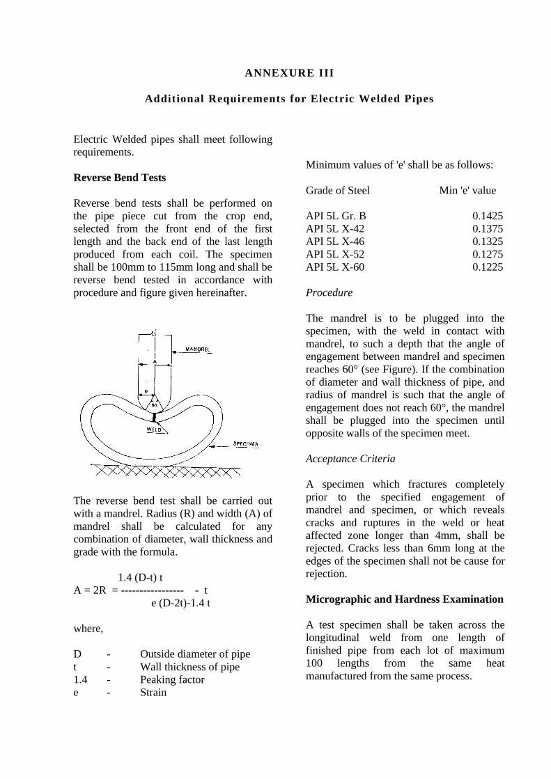
ANNEXURE III
Additional Requirements for Electric Welded Pipes
Electric Welded pipes shall meet following requirements.
Reverse Bend Tests
Reverse bend tests shall be performed on the pipe piece cut from the crop end, selected from the front end of the first length and the back end of the last length produced from each coil. The specimen shall be 100mm to 115mm long and shall be reverse bend tested in accordance with procedure and figure given hereinafter.
The reverse bend test shall be carried out with a mandrel. Radius (R) and width (A) of mandrel shall be calculated for any combination of diameter, wall thickness and grade with the formula.
1.4 (D-t) tA = 2R = ----------------- - t
e (D-2t)-1.4 t where,
D - Outside diameter of pipet - Wall thickness of pipe1.4 - Peaking factore - Strain
Minimum values of 'e' shall be as follows:
Grade of Steel Min 'e' value
API 5L Gr. B 0.1425 API 5L X-42 0.1375API 5L X-46 0.1325API 5L X-52 0.1275API 5L X-60 0.1225
Procedure
The mandrel is to be plugged into the specimen, with the weld in contact with mandrel, to such a depth that the angle of engagement between mandrel and specimen reaches 60° (see Figure). If the combination of diameter and wall thickness of pipe, and radius of mandrel is such that the angle of engagement does not reach 60°, the mandrel shall be plugged into the specimen until opposite walls of the specimen meet. Acceptance Criteria
A specimen which fractures completely prior to the specified engagement of mandrel and specimen, or which reveals cracks and ruptures in the weld or heat affected zone longer than 4mm, shall be rejected. Cracks less than 6mm long at the edges of the specimen shall not be cause for rejection.
Micrographic and Hardness Examination
A test specimen shall be taken across the longitudinal weld from one length of finished pipe from each lot of maximum 100 lengths from the same heat manufactured from the same process.

These specimens shall be polished and etched for micro-examinations. The examinations shall provide evidence that heat treatment of weld zone is adequate and there is no un-tempered martensite left.
Hardness measurements on each specimen shall be made as indicated in figure given herein after in accordance with ASTM E-32. The maximum difference in hardness between base material and any reading taken in the Heat Affected Zone (HAZ) shall be less than 80 points Vicker's HV10.

ANNEXURE IV
MINIMUM INTER DISTANCES FOR VARIOUS STATION FACILITIES
S.No. From / To 1 2 3 4 5 6 7 8 9 101 Small Compressor/
Pump House- 15 15
15
16 30 15 1515
16
2 Main Compressor House
15 - 1515
30 30 15 1530
30
3 Gas Handling System (PB /GC)
15 15 - 5 16 30 15 15 5 16
4 Equipment Room 15 15 5 - - 30 15 15 5 165 Control Room /Office
building 16 30 16 - - 30 15 15 5 -
6 Fire Pump House/Fire water storage tanks
30 30 3030
30 - - 3012
-
7 Water Spray Deluge Valve
15 15 1515
15 - - 15 - 16
8 Cold Blow Down15 15 15
15
15 30 15 - 5 30
9 Compound wall 15 30 5 5 5 12 - 5 - 510 Elect Sub station,
16 30 1616
- - 16 30 5 -
* Any distance suitable for constructional and operation convenience.1. All distances are in metres. All distances shall be measured between the nearest points on the
perimeter of each facility2. Hot elevated flare shall be located 90 mtr away and ground flare shall be located 150 mtr
away3. For the distance from compound wall, the distance mentioned in this table and the
requirement of local bylaws(if any) which ever is higher shall govern.PB – Pig receiver / Launcher Barrel, GC- Gas Coolers / Meters / filters

AN
TI-
SU
RG
E L
INE
SUCTION BLOWDOWN
PIG
LA
UN
CH
ER
PIG
RE
CE
IVE
R
DISCHARGE BLOWDOWN
UNIT BLOWDOWN
UNIT BLOWDOWNCOMPRESSOR
COMPRESSOR
ST
AT
ION
RE
CY
CLE
VALVE
LO
LO
INLET SCRUBBER
TYPICAL COMPRESSOR STATION SCHEMATIC
FUEL GASCONDITIONING
SKID
VALVEDISCHARGE
STATION
PRESSURIZING
MAIN LINEFROM
STATION
BY
-PA
SS
ST
AT
ION
TO MAIN LINE GAS AFTERCOOLER
ANNEXURE V

ANNEXURE VI
LIST OF APPLICABLE STANDARDS AND REFERENCES
This standard shall be read in conjunction with the following standards, codes and publications:
(i) ASME B31.8 Gas Transmission and Distribution Piping Systems.(ASME 3 Park Avenue, New York, NY USA 10016.
www.asme.org)
(ii) API -617 Centrifugal Gas Compressors(iii) API- 618 Reciprocating Gas compressors(iv) API- 11P Other gas compressors(v) API 1102 Recommended Practice for Steel Pipelines Crossing Railroads
and Highways. (vi) API 1104 Standard for Welding Pipelines and Related Facilities. (vii) API 1107 Recommended Pipeline Maintenance Welding Practices.(viii) API 1109 Recommended Practice for Marking Liquid Petroleum Pipeline
Facilities. (ix) API 1110 Recommended Practice for Pressure Testing of Liquid Petroleum
Pipelines. (x) API 500C Classification of Locations for Electrical Installations at Pipeline
Transportation Facilities.(xi) API- 5L Specification for Line pipes(xii) API- 6D Pipeline Valves(xiii) ASME Section VIII Boiler and Pressure Vessel Code
Division 1 Pressure VesselsDivision 2 Alternate Rules for Pressure Vessels
(xiv) ASME Section IX Welding Qualifications(xv) MSS-SP-50 Pipe Hangers and Supports Materials, Design and Manufacture.(xvi) MSS-SP-69 Pipe Hangers and Supports - Selection and Application. (xvii) NACE-RP-01-69 Recommended Practice Control of External Corrosion on
Underground or Submerged Metallic Piping Systems. (xviii) NACE-RP-01-75 Recommended Practice - Control of Internal Corrosion in
Steel Pipelines Systems. (xix) ISA S-75.01 Flow evaluation for sizing control valve(xx) ISA S-75.02 Control valve test procedure(xxi) IEC – 79 Electrical Apparatus for Explosive Gas Atmosphere(xxii) IEC – 529 Degree of protection Provided by Enclosures.
References
ASME B 31.8 – Gas Transmission and Distribution Piping Systems API 1104 - Welding procedures and welders for welding of gas pipelines.
ASME Boiler and Pressure Vessel (BPV) Code Section IX - Welding procedures and welders, for station piping.
IS-5572 - Electrical area classification of Installation for selection of Electrical Equipment
IS – 5571- “Guide for selection of Electrical Equipment for Hazardous Area”. IS 3043 – For earthing of all electrical equipment, systems, structures and fencing, etc. IS:2309 – Lightening protection

ISO 14313 Valves NACE SP-0177 Mitigation of AC and lightening effects
Secretary, PNGRB
![PNGRB ActTHE PETROLEUM AND NATURAL GAS REGULATORY BOARD ACT, 2006 NO. 19 OF 2006 [31st March, 2006] PNGRB Act:- ... (excluding mineral colza oil and turpentine substitute), which conforms](https://static.fdocuments.in/doc/165x107/5ea1fd0870ef586ab27a51ae/pngrb-act-the-petroleum-and-natural-gas-regulatory-board-act-2006-no-19-of-2006.jpg)


