PNEUMATICALLY DRIVEN VEHICLE WITH …iaeme.com/MasterAdmin/Journal_uploads/IJMET/VOLUME_7... ·...
16
http://www.iaeme.com/IJMET/index.asp 410 [email protected] International Journal of Mechanical Engineering and Technology (IJMET) Volume 7, Issue 3, May–June 2016, pp.410–425, Article ID: IJMET_07_03_037 Available online at http://www.iaeme.com/IJMET/issues.asp?JType=IJMET&VType=7&IType=3 Journal Impact Factor (2016): 9.2286 (Calculated by GISI) www.jifactor.com ISSN Print: 0976-6340 and ISSN Online: 0976-6359 © IAEME Publication PNEUMATICALLY DRIVEN VEHICLE WITH RECHARGEABLE BATTERY DURING DRIVE- AN EXPLORATORY STEP IN ADDRESSING ENVIRONMENTAL POLLUTION U Guru Sri Charan, P.D Phanindra, A.S.R.Murty Department of Mechanical Engineering, KLEF/K L University, Vaddeswaram, A.P, India ABSTRACT Energy can be stored in compressed air form at very high pressures running to a few dozens of atmospheres. The compressed air properly controlled, timed, released through pressure regulators etc., can be used to run Pistons that in turn can drive an engine. This compressed air can be furnished through already available accumulator as well as through an on board compressor. A battery which gets duly charged as per needs on line in a running vehicle through solar energy depending on availability or offline when the vehicle is stationary can support to run a d.c motor too which in turn can drive the vehicle. This works as a redundant system to attend the drive power needs or in managing to reach destinations. Even existing hybrid vehicles can have this stand-by pneumatic power support. In this work a Pneumatic powered accumulator, solar panels(PVC),battery, d.c motor, compressed air driven engine, air compressors main and auxiliary ( both compressors reciprocating only) combination is considered to drive a specified vehicle for a defined payload peak. One can expect future pneumatic vehicles with back-up battery and with brushless d.c motors (they don't produce carbon dioxide).Battery shall be re-charged through solar cells and pneumatic means also. The failures of previous attempts at a pneumatic vehicle may get benefitted from our work. Key words: Compressed Air, Pneumatic Engine, Primary and Auxiliary Accumulators, Solenoid and Diaphragm Compressor, Solar Energy Support, Pneumatic Car
Transcript of PNEUMATICALLY DRIVEN VEHICLE WITH …iaeme.com/MasterAdmin/Journal_uploads/IJMET/VOLUME_7... ·...

http://www.iaeme.com/IJMET/index.asp 410 [email protected]
International Journal of Mechanical Engineering and Technology (IJMET) Volume 7, Issue 3, May–June 2016, pp.410–425, Article ID: IJMET_07_03_037 Available online at http://www.iaeme.com/IJMET/issues.asp?JType=IJMET&VType=7&IType=3 Journal Impact Factor (2016): 9.2286 (Calculated by GISI) www.jifactor.com ISSN Print: 0976-6340 and ISSN Online: 0976-6359
© IAEME Publication
PNEUMATICALLY DRIVEN VEHICLE
WITH RECHARGEABLE BATTERY
DURING DRIVE- AN EXPLORATORY STEP IN ADDRESSING ENVIRONMENTAL
POLLUTION
U Guru Sri Charan, P.D Phanindra, A.S.R.Murty
Department of Mechanical Engineering,
KLEF/K L University, Vaddeswaram, A.P, India
ABSTRACT
Energy can be stored in compressed air form at very high pressures
running to a few dozens of atmospheres. The compressed air properly controlled, timed, released through pressure regulators etc., can be used to run Pistons that in turn can drive an engine. This compressed air can be
furnished through already available accumulator as well as through an on board compressor. A battery which gets duly charged as per needs on line in a
running vehicle through solar energy depending on availability or offline when the vehicle is stationary can support to run a d.c motor too which in turn can drive the vehicle. This works as a redundant system to attend the drive
power needs or in managing to reach destinations. Even existing hybrid vehicles can have this stand-by pneumatic power support. In this work a
Pneumatic powered accumulator, solar panels(PVC),battery, d.c motor, compressed air driven engine, air compressors main and auxiliary ( both compressors reciprocating only) combination is considered to drive a
specified vehicle for a defined payload peak. One can expect future pneumatic vehicles with back-up battery and with brushless d.c motors (they don't
produce carbon dioxide).Battery shall be re-charged through solar cells and pneumatic means also. The failures of previous attempts at a pneumatic vehicle may get benefitted from our work.
Key words: Compressed Air, Pneumatic Engine, Primary and Auxiliary Accumulators, Solenoid and Diaphragm Compressor, Solar Energy Support,
Pneumatic Car

Pneumatically Driven Vehicle with Rechargeable Battery During Drive- An Exploratory Step In Addressing Environmental Pollution
http://www.iaeme.com/IJMET/index.asp 411 [email protected]
Cite this Article: U Guru Sri Charan, P.D Phanindra and A.S.R.Murty, Pneumatically Driven Vehicle with Rechargeable Battery During Drive- An
Exploratory Step In Addressing Environmental Pollution. International Journal of Mechanical Engineering and Technology, 7(3), 2016, pp. 410–425.
http://www.iaeme.com/currentissue.asp?JType=IJMET&VType=7&IType=3
1. INTRODUCTION
We see many cars where energy efficiency or fuel economy have been addressed and this battle will continue. The one major problem created by the automobile number
and their quality is pollution that still persists despite an equally seriously fought battle by many automobile manufacturing stalwarts. We are very much aware of the pollution and consequent health and environment related problems. In the attempt to
make the planet greener the very vehicle drive style perhaps can adopt a revolutionary step. This step can be achieved through "avoiding of fuel burning while running the
vehicle". Use storing/accumulating energy elsewhere and "bring the stored energy on board strategically and not generate energy on board the road riding vehicle" is the key point. Attempt at concentrating on efficiency in fuel in achieving there centrally
at this storing centre may fetch overall results which are much better. This accumulation of energy also may be attempted in various styles. We consider here in
our work compressing air. Use the compressed air-cylinder (accumulator) to drive the vehicle. Do attempt on- line compression of air in a working and supporting manner to main energy source so that the air inlet that is compulsory for any moving vehicle is
also available and it is utilised. Besides, charge a battery too when the vehicle is running during the availability of sunshine through solar cells. Thus the vehicle can
run in dual modes viz., by compressed air engine (with auxiliary compressed air made on board inclusive) and by d.c motor deriving power from the rechargeable battery which is initially installed in fully charged state. It gets recharged through solar
panels. A schematic illustrating this is shown in figure 1.The battery mode is useful to some how move the vehicle through very short distances of 1/2 km and is meant for
emergency.
Figure 1
1.1. A brief description of the Schematic
The objective of this work is to arrive at parameters desirable for working drive
systems of pneumatic engines. From very small vehicles with total payload 500 kg to about a ton the principles discussed will be valid. About losses of energy at various

U Guru Sri Charan, P.D Phanindra and A.S.R.Murty
http://www.iaeme.com/IJMET/index.asp 412 [email protected]
sources a full and comprehensive attention was not given, but the actual designer can post those values to his needs and obtain full set of design factors.
The primary accumulator contains air at 300 bar or above and is out sourced and installed.(1)The air from this as per operational cycle will enter the pneumatic
engine's cylinder (2) to do work. It is a "two stroke engine-similar" engine. The exhaust air from this which can be 150 to 3 bar will go to Auxiliary/secondary compressor (3).Secondary compressor is on board compressor deriving air from
solenoid-diaphragm pump (4)as well as the brushless D.C motor (5).It is sent through a filter (7) as the air sucked from atmosphere (6)will have impurities. The secondary
compressor having the final pressure at 300 bar can also supply to pneumatic engine but it is much less than the primary compressor in covering distance (20/30 km only).This is only to supply air when primary compressor air is inadequate in quantity
and specification viz., pressure limits. A battery charged (8) by solar panels (9) total area 0.8-1.2 sq m runs the brushless D.C motor (5) which can supply the needs of
dash board as well as help any additional torque to main engine or auxiliary devices on board.
1.2. Review of Literature
Through a history of two millennia starting from the bellows of street moving forger
or tin smith to jet engines using centrifugal compressors of high rating and fluid logic elements in 20th century pneumatics passed through a long history and multiplicity of
advancements (1).The great Soviet Encyclopædia (2) despite ideological slants and disagreeable ownership attributions gives useful material. We quote from that "Pneumatic methods of automation are often given preference over electronic
methods. This is mainly because pneumatic equipment is by nature explosion-proof and fireproof and, in addition, is better suited to operation under industrial production conditions, particularly if the air in production areas is badly polluted or if the
production processes generate strong electromagnetic fields. Because of its low speed of response, pneumoautomatic hardware is used in control systems for slow processes
and in cases where performance of a very large number of computations is not necessary for execution of a control algorithm. In spite of these limitations the field of application of pneumoautomatic hardware is very broad. In particular, it is used in
most control systems for production processes. It is the prinicipal method of automation in the chemical and petroleum-refining industries; in petroleum, gas, and
coal-extraction enterprises and in the transportation of petroleum and gas." Well, it summarises nicely how effective useful can be pneumatics in various applications.
In a publication entitled "Latest Developments of a Compressed Air Vehicle: A
Status Report" by S. S. Verma (3) a good review was conducted and the observations bring also vehicles that were attempted with accumulator inclusive in the design. The
paper discusses small cars as well as scooters run on pneumatic power. The discouraging factors mentioned there in are depletion of pressure as use of miles/ kilometres travelled increases there by fall in speed and further scope to plan running
speeds of vehicle becoming alarming. However, the above issues can be addressed through keeping working pressures within specified bands like 300-120 bars and
handling the exhausts for recompression. This is one of the main ideas of the present work.
Outsourcing the development work to a consulting firm CQFD Air Solution, the
work of Airpod an automobile run on compressed air(5) and encouraging

Pneumatically Driven Vehicle with Rechargeable Battery During Drive- An Exploratory Step In Addressing Environmental Pollution
http://www.iaeme.com/IJMET/index.asp 413 [email protected]
participation as a promotional project is also quite interesting and it optimistically views at a future pneumatic car and it is also supported by an insurer AVIVA.
A pneumatic engine where combustion was also included was discussed (6).Their point is well summarised n their abstract-"Although internal combustion engines
display high overall maximum global efficiencies, this potential cannot be fully exploited in automotive applications: in real conditions, the average engine load (and thus efficiency) is quite low and the kinetic energy during a braking phase is lost. This
work presents a new hybrid pneumatic- combustion engine and the associated thermodynamic cycles, which is able to store energy in the form of compressed air.
This energy can be issued from a braking phase or from a combustion phase at low power. The potential energy from the air tank can then be restored to start the engine, or charge the engine at full load. The regenerative breaking and the suppression of the
idling phases could provide an improvement in terms of fuel economy as high as 15% or more if combined with engine downsizing." While the above mentioned vital
points can not be disputed, the engine will also involve combustion on board has to be noted. The senior author of this work and ref.4 PASCAL HIGELIN is pursuing this problem of pneumatic engine for a long period as we can notice from his publications
(4,6) and the cross references thereof.
1.3. Overall benefits of the present system and comparisons
The present work considers drive through already compressed air up to 300 bar
obtained for accumulator in cylinder forms. This available drive source supported by on line collection of and compressing it to maintain an auxiliary accumulator is discussed. A solar powered battery gives further support to a very limited distance
coverage. Since no on board combustion is there including from the brushless d.c motor the question of pollution does not arise.
The limitations of payloads, total distance the vehicle can cover and speed limits
this methodology can not promise. However, we can make the vehicle suitable for crowded and narrow streets typically like in India where three wheelers, two
wheelers, travel needs not exceeding urban limits by light vehicles etc., can help thwarting the pollution problem to a great extent.
1.4. A Note on present work
An optimisation done on the drive-system controlled by a micro-processor and
controller can help the methodology as well as efficiency further. This comprehensive hybridisation may come as a very attractive alternative. We have to conduct full
feasibility studies and economic viabilities especially when we can afford large scale applications. Drills and fettles are already in vogue in mines and foundries for a long time. This idea of stored energy driving vehicles big or small can be taken further. It
is true that automobile companies in India and abroad failed in the past in their attempts to put pneumatic vehicles in the streets. An analysis of these mission failures
shall be attempted along with possible and worth trying alternatives shall appear in the forth coming work of the authors. A hybridisation proposed in this work is different from what was attempted earlier. Instead of attempting to derive all the
pneumatic drive energy only from atmosphere an an already charged (pressurised) cylinder or an accumulator is taken up besides attempting to recharging on line
another accumulator. The inlet pressure with full rated pressure of accumula tor is let in to the cylinder of the drive' pneumatic engine' and its use is also upto a fixed lower pressure to maximise the efficiency. Recycling is another feature introduced for the

U Guru Sri Charan, P.D Phanindra and A.S.R.Murty
http://www.iaeme.com/IJMET/index.asp 414 [email protected]
used air in engine. The special features of the engine and other components are described elsewhere in this work we present the main rudiments but not the complete
system we have in our plans. This point has to be carefully noted.
2. SYSTEM DESCRIPTION MAIN COMPONENTS WISE
We shall take up the vehicle drive system details main components-wise in detail. Connecting, regulating, controlling, transmitting elements are not taken up as the conventional and handbook information can be readily obtained. Only a brief
discussion is given at the end of the list of main components.
First we consider auxiliary components. Connecting pipes should bear respective
pressures to be carried without bursting. Dias should be such that flow rates in side are well permissible. Ends should be well sealed. In general with the availability of present technology sealing any where for high pressures as well as vacuums is not a
problem inclusive of gaskets and sealing rings of all shapes and sizes.
Regulating valves should be carefully selected for range of pressures, sensitivity,
leaks, display of pressure through suitable gauges wherever possible. So also are controlling valves. As mentioned earlier the host of handbooks and Internet guiding tools nowadays can surely solve these problems if we judiciously apply our discretion
and design criteria.
Coming to the main components we have compressors first. Readily available
compact low weight positive displacement compressors giving 300 bar output for given flow rates are available. The pneumatic engine that provides main drive torque to the shafts a through gear box, couplings etc., is also described. The compressors
and details are also discussed below.
Only solenoid-diaphragm pump mentioned is to be fabricated as per design by us.
This is also described long with primary and auxiliary accumulators below in greater detail. The main drive is called pneumatic engine and it is described in 2.2. Note worthy point is, it can derive power or drive from both sources viz., compressed air as
well as from battery, the later being slower and is meant for covering short distance. It is only a redundancy.
2.1. Use of gases or air and pneumatic technology
Pneumatic systems especially in fixed installations as in factories use compressed air because a dependable and sustainable supply can be achieved by compressing only atmospheric air which has to be filtered and purified. After the moisture is removed
usually small quantity of oil is also added at the compressor to prevent corrosion and facilitate lubrication of components.
Compressed air technology has been in use in different pneumatic systems already. It is passing through research for improvements from several aspects for several needs. Other gases like nitrogen and carbon dioxide are also in use.
2.2. Engine working on compressed air (Pneumatic engine)
A compressed-air engine adopts a pneumatic actuator a positive displacement device
doing the work for moving piston/s. An accumulator/stored compressed air cylinder or tank is the energy source. This accumulator has to be furnished and can be outsourced easily. Let us call this engine through our definition say 'Pneumatic
Engine'. The main store of energy supplied to this engine is the main accumulator. Since pressure regulating valves can be obtained for many combination pressures it
should not be a problem to achieve this step. Cost criteria and comparisons are

Pneumatically Driven Vehicle with Rechargeable Battery During Drive- An Exploratory Step In Addressing Environmental Pollution
http://www.iaeme.com/IJMET/index.asp 415 [email protected]
deliberately dropped here. The engine with inlet valve for entry of air and the exhaust valve for the air escape is shown in figure.
Engine figure with cylinder, piston, VTD
Figure 2
Figure 3
The pressure of air entering the piston helps the movement of piston in the
cylinder. This is similar to fuel burnt cylinder and piston action mechanism. The similarity is sought only for easy understanding and minute design stage naturally some similarities will start fading. Single acting cylinder-piston mechanism is only is
attempted as this work is in the beginning stages of development though there are plans to go in for double acting equipment.
After the work done the left over air goes to through the exhaust for recycling. We should bear in mind that even purification of air can be minimised if the same air is recycled wherever possible.

U Guru Sri Charan, P.D Phanindra and A.S.R.Murty
http://www.iaeme.com/IJMET/index.asp 416 [email protected]
The engine cylinder is filled by the air at high pressure when the piston is at TDC. The pneumatic engine can be conceived as a modification of the of the classic two-
stroke engine. The crankshaft will have the traditional rolling bearing. The lubrication will be also at low temperatures as the heat generated problem is not there in this
engine. The oiling of the bearings and the cylinder surface is ensured by a small oil pump or by oil drop valve in a closed cycle. The engine has a transfer port because delivering of the air is not from the crankcase. Only one exhaust port is used for the
air outlet from the cylinder in the present design while it can be multiple ports also to utilise the potential energy of compressed air completely. From the exhaust port a
vent and a pipe connection is given to the air to join pure air for recycling. The engine has an injector in the form of a valve controlled by the mechanical linkages verified constantly by electronic unit viz., micro-controller, micro-processor and the
supporting circuitry for accuracy and alarm. This electronic control is more an accuracy and monitoring job helping tool than valve operating device per se. The
accumulator contains air at high pressure and the initial stored air is capable of serving a 100 km travel need at approximately 40/50 km/ hr speeds. The accumulator pressure of about 300 bar is reduced by pressure regulator valve to lower pressures
say down to20/50/60 bar and this pressure is used in the engine for the drive of the piston/ s. Lower injection pressures up to about 20-30 bar may be possible depending
on the vehicle and total payload. The pressure is controlled by pipe of small diameter (about 5-8 mm) to the valve sensor. The volumetric flow rate through the valve is rather high in comparison to the liquids in fuel injection but the mass flow rate is not
so. Use of an electromagnetic stem valve naturally requires a high voltage and high electric power also. To serve this need an electromagnetic or pneumatic valve can be
used. The recycled air will join the air circuit at a later stage.
The pressure of air entering the piston helps the movement of piston in the cylinder. This is similar to fuel burnt cylinder and piston action mechanism. The
similarity is sought only for easy understanding and minute design stage naturally some similarities will start fading. Single acting cylinder-piston mechanism is only is
attempted as this work is in the beginning stages of development though there are plans to go in for double acting equipment.
After the work done the left over air goes to through the exhaust for recycling.
We should bear in mind that even purification of air received from atmosphere can be minimized if the same air from engine exhaust is recycled.
When the vehicle is moving it collects air at some velocity to which suitable correction like favorable wind or unfavorable wind and through a solenoid valve mechanism we may achieve an initial compression of this to say a maximum of 2/3
bar that includes the velocity head of in flowing air while the vehicle moves. After this stage the air will pass through a filter for purification. Then it goes to another
reciprocating compressor that is used to compress the air to say 300bar or so (10%-20% more than the drive pressure of the pneumatic engine of the vehicle is advisable ).This air is stored in the auxiliary accumulator. When needed and as commanded by
the linkage mechanisms/micro-controller air supply from this cylinder will substitute that of main accumulator. The pressure of air at inlet point of engine being 300 bar
plus the quantity of air allowed in to the cylinder will decide the speed. Using the leverage mechanism and gears suitably it is possible to touch 50 km/ hr peak speed with max payload of a ton.

Pneumatically Driven Vehicle with Rechargeable Battery During Drive- An Exploratory Step In Addressing Environmental Pollution
http://www.iaeme.com/IJMET/index.asp 417 [email protected]
2.2.1. Gearbox
The gearbox having primarily two possible drives one from battery and the other from
accumulator has the rest of the configuration as any other gearbox with multiple speeds and reverse gear. The accelerator for pneumatic mode is in allowing more air
slowly as the pedal commands while the brush less d.c motor speed decides the other mode speed. This is special in the sense that the main drive can be from either pneumatic engine or from battery in emergency. There on wards for speed changes
and reversals the routine gearbox pattern can be followed.
2.3. Main/Primary Accumulator
Accumulators usually are installed in hydraulic systems to store energy and to smooth
out pulsations. Typically, a hydraulic system with an accumulator can use a smaller pump because the accumulator stores energy from the pump during periods of low demand. This energy is available for instantaneous use, released upon demand at a
rate many times greater than what could be supplied by the pump alone.
Accumulators also can act as surge or pulsation absorbers, much as an air dome is
used on pulsating piston or rotary pumps. Accumulators will cushion hydraulic hammer, reducing shocks caused by rapid operation or sudden starting and stopping of power cylinders in a hydraulic circuit. There are four principal types of
accumulators: the weight-loaded piston type, diaphragm type, spring type, and the hydro-pneumatic piston type. The weight- loaded type was the first used, but is much
larger and heavier for its capacity than the modern piston and bladder types. Both weighted and spring types are infrequently found today. Hydro-pneumatic accumulators, are the type most commonly used in industry. Compressed air brought
in the form of a replaceable cylinder straight in the vehicle can be connected in less than a minute's time. The regulator sending the drive air to piston will have a suitable connection to the primary accumulator.
The air used in the pneumatic engine will go to the filtered air line that goes to the auxiliary accumulator. Thick plate theoretical calculations for this accumulator as
well as for all other cylinders under pressures are briefly given below. Primary accumulator stores air of volume at 300+ or - 20 bars. So al will be secondary accumulator. But, this has smaller capacity.
2.3.1. Wall thickness calculations in all pressure cylinders:
By pressure cylinder we mean the engine cylinder, primary accumulator and
secondray accumulator the ends of all the cylinders will be suitabley rounded of to reduce stess contrations depending on the maximum pressure which is assumed to be 300 bar in all the cases for the needed diameter in the three driffrent places the wall
thickness is detiminned as per the following caculation which will sight only in example
Taking the incase of accumluator given the following:
Thickness formula = (outer diameter – inner diameter)
Max dia = 0.203m Min dia = 0.198m
Min thickness = 0.005m Max thickness = 0.010m
V = πr 2h
Max volume = 650 cu in 10.6 liters Min volume = 480 cub in 7.4 liters
Max height = 40.5 inches 1m Min height = 20.5 inches 0.5m

U Guru Sri Charan, P.D Phanindra and A.S.R.Murty
http://www.iaeme.com/IJMET/index.asp 418 [email protected]
Max pressure = 10000 psi 600 bar Min pressure = 5000 psi 300 bar
Assuming Lamé’s Equations with
= Hoop stress Pi = internal pressure Po = external pressure ri = internal radius ro =
external radius r = radius at point of interest (usually ri or ro)
Substuting: Internal Pressure = 3e+7 Pa External Pressure = 101325 Pa
Internal Radius=0.099m External Radius=0.1015m Radius at Point of Interes = 0.5 m
We obtain hoop stress = 608602259.7394177 Pa, 88269.97 psi the axial stress in a closed-ended thick-walled cylinder:
With = axial stress, Pi = internal pressure, ri = internal radius, ro = external radius. Internal Pressure = 3e+7 Pa, Internal Radius = 0.099 m External
Radius = 0.1015 m. We obtain axial stress = 35302.1853644 Pa.
Assumig 4inch =10cm diameter of the rotating wheel the velocity is given by
V =∏DN/60 where pi = ∏=3.14 for various speeds of vechile we can show
10km/h 20km/h 30km/h 40km/h 50km/h 60km/h 70km/h 80km/h 90km/h 100km/h
0.03rpm 3.7rpm 5.6 rpm 7.5 rpm 9.4 rpm 11.2 rpm 13.2 rpm 15.0 rpm 16.9 rpm 18.8 rpm
Assuming: Torque = F/D =1.4 Nm Break power = = 0.98 kj/s =1.34 hp
We can round it off to say 1.5 or 1.6 hp which can take a pay load of 1000 kg
2.3.2. A note on efficiency
Efficiency definition has to be carefully observed in the above. While carnot’s efficiency looks at input temperature and output temperature irrespective of the materials involved a simplified formula like T1-T2/T1 is easy to understand. But
when it comes to combination of energies like pneumatic, thermal, frictional, transmission related etc., efficiency is a more involved factor. While pneumatic
efficiency can cross 80% with less efforts it is very difficult to cross 30% in thermodynamic efficiency.
2.4. Auxiliary accumulator
We keep another cylinder for storing extra reserve compressed air that is obtained when the vehicle runs. This is auxiliary accumulator. In this work main accumulator
is of 300/400 bars and auxiliary accumulator is also of same rating but its capacity is around 20% only of main accumulator. Hence, if total distance covetable is 100 km, we can expect to cover a maximum of 20 km with the help of auxiliary accumulator.
The working pressure needed to run the pneumatic engine 300 bars or around these values. It should be borne in mind that the auxiliary accumulator is designed hardly
adequate to run the vehicle as a standby for 20 kms. Like fuel indicator these reserve indicators can be designed and installed in the vehicle. The timings of air release from accumulator to drive the Piston/s and the corresponding valve openings are taken care
at design stage which leaves adequate scope for corrections and fine tuning as well. The piston engine can be double acting too. Through a comparison we find
reciprocating compressor is better than a a centrifugal/turbo compressor which point is not taken for details in this work.
The pressure of air entering the piston helps the movement of piston in the
cylinder. This is similar to fuel burnt cylinder and piston action mechanism. The
60/2 NT

Pneumatically Driven Vehicle with Rechargeable Battery During Drive- An Exploratory Step In Addressing Environmental Pollution
http://www.iaeme.com/IJMET/index.asp 419 [email protected]
similarity is sought only for easy understanding and minute design stage naturally some similarities will start fading. Single acting cylinder-piston mechanism is only is
attempted as this work is in the beginning stages of development though there are plans to go in for double acting equipment.
After the work done the left over air goes to through the exhaust for recycling.
We should bear in mind that even purification of air can be minimized if the same air is recycled wherever possible.
When the vehicle is moving it collects air at some velocity to which suitable correction like favorable wind or unfavorable wind and through a solenoid valve
mechanism we may achieve an initial compression of this to say a maximum of 2/3 bar that includes the velocity head of in flowing air while the vehicle moves. After this stage the air will pass through a filter for purification. Then it goes to another
reciprocating compressor that is used to compress the air to say 100 bar or so (10%-20% more than the drive pressure of the pneumatic engine of the vehicle).This air is
stored in the auxiliary accumulator. When needed and as commanded by the linkage mechanisms/micro-controller air supply from this cylinder will substitute that of main accumulator.
The output air at about 2/3 bar from the solenoid-diaphragm pump after passing through filter and compressed to 300 plus bar will be recycled.This will reduce
general air purification efforts and the consequent energy losses.
3. PRELIMINARY COMPRESSOR THROUGH SOLENOID AND DIAPHRAGM MECHANISM
Air sucked or received when the vehicle moves will have finite velocity head. The air also will have adequate contamination which is ubiquitous almost due to wide
pollution around. This air is initially compressed through the use of a solenoid and diaphragm mechanism. It is illustrated in figure
Solenoid and diaphragm pump
Figure 4

U Guru Sri Charan, P.D Phanindra and A.S.R.Murty
http://www.iaeme.com/IJMET/index.asp 420 [email protected]
The output air at about 2/3 bar from the solenoid-diaphragm pump after passing through a filter will be recycled. This will reduce general air purification efforts and
the consequent energy losses
4. OPERATING THERMODYNAMIC CYCLE IN PNEUMATIC
ENGINE
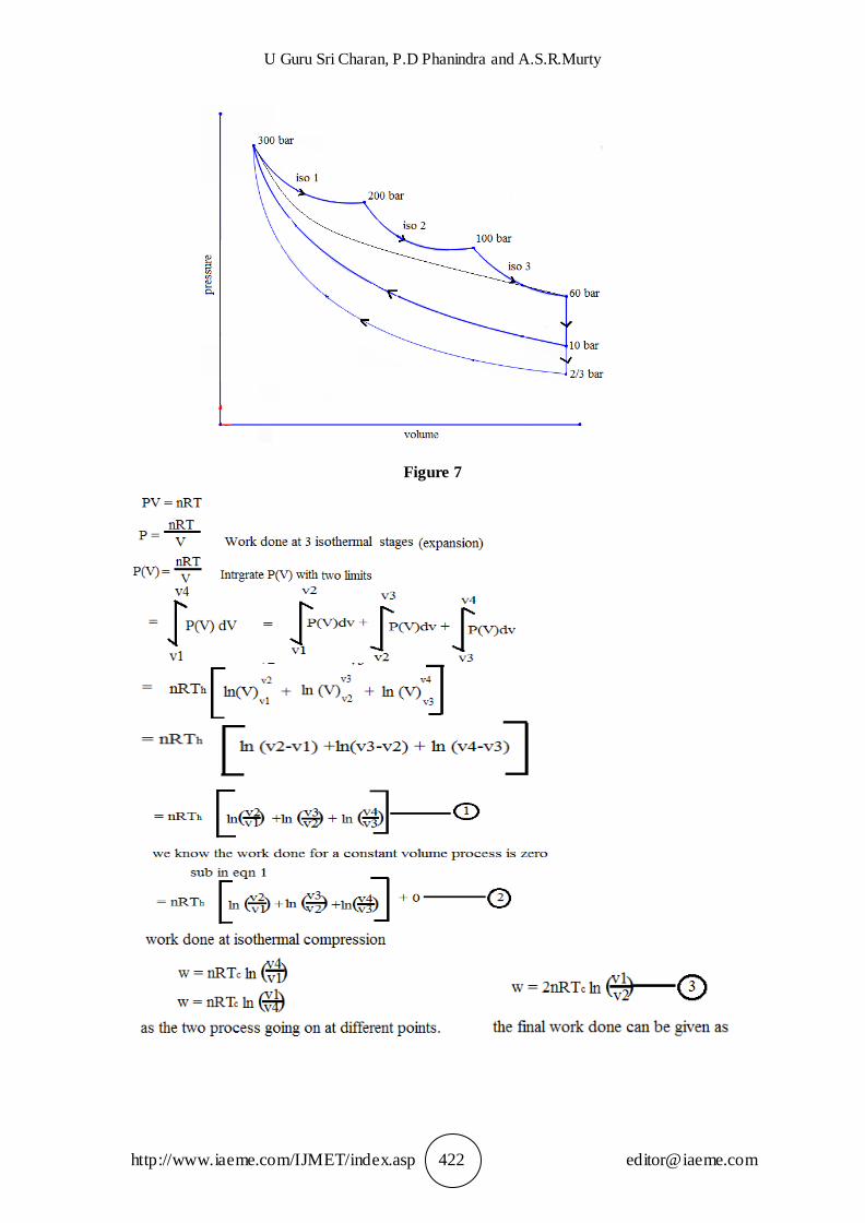
When the piston at TDC and when minimum volume is available maximum pressure
at 300 bar is furnished at point 1 (Figure: 4). Piston moves to point 2 where by the volume increases and the pressure falls while the process is iso-thermal, ideally speaking. But in actual practice as the volume expands and pressure falls the
surrounding walls of the cylinder take the heat from the air inducing a fall in temperature step by step in multiple stages. If we consider only three stages the
expansion will be as shown in (Figure: 7).
It is difficult to come to any conclusive results on the calculations of work done in the thermodynamic cycle without making some assumptions.
Figure 4
Ideal heat input, heat output and work done will be as shown in (Figure: 5).
The corresponding equations are given below (Figure 5). Idealizing further the Carnot cycle as shown in Figure: 6 and the legend below.
Figure 5

Pneumatically Driven Vehicle with Rechargeable Battery During Drive- An Exploratory Step In Addressing Environmental Pollution
http://www.iaeme.com/IJMET/index.asp 421 [email protected]
Figure 6
We arrive at a maximum efficiency of say 50% ! With three stages in the iso-thermal expansion from 300 bar to 100 bar and then leaving the air at 2/3 bar in to the
recycle mode the piston will start moving with its kinetic energy also supported by suitable fly wheel MI and reach the TDC again. It is shown in Figure:7 below followed by calculations thereof
U Guru Sri Charan, P.D Phanindra and A.S.R.Murty
http://www.iaeme.com/IJMET/index.asp 422 [email protected]
Figure 7

Pneumatically Driven Vehicle with Rechargeable Battery During Drive- An Exploratory Step In Addressing Environmental Pollution
http://www.iaeme.com/IJMET/index.asp 423 [email protected]
5. SOLAR PANELS AND RECHARGEABLE BATTERY
Solar panels of area between 0.4-0.8 sq m shall be installed with suitable circuitry to charge a battery. This battery power can be used for main drive if so designed or to help dashboard equipment and the illumination required thereof. The battery gets
charged only when there is solar energy received in limited but in a cumulative manner. Hence its design should address the net KWh available to drive the vehicle in
stand alone mode up to a maximum 4/5 km in the context of our nation.
6. D. C MOTOR AND DRIVE CONTROLS
The conventional easily available lead acid battery with 12V is only planned to
deliver maximum current up to Amps and also a total storable kWh will be. Even the continual charging of battery by solar power is included and is not assumed more than
5kWh in a day at best and 0.5 kWh/ per day in the worst case. An auxiliary battery charging unit through a generator run by main shaft can be also incorporated but we have not planned n this work. The speed of brushless D.C motor is controlled the
usual way. It is deliberately chosen brushless as the emission of carbon dioxide is eliminated through the brushes heat and spark.
7. CONCLUSIONS
From the study of exploring the pneumatically driven vehicle with the support of an auxiliary reciprocating compressor and also a rechargeable battery driving a d.c
brushless motor that supports alone the main drive in standalone mode for 4/5 km travel we can draw the following conclusions:
1. The two-stroke engine similar reciprocating compressor is the best amongst the possible alternatives that include four stroke engine and axial flow compressor. Only it can enable best utilization of the compressed air.
2. The proposed pneumatic engine has very good torque characteristics - higher value at lower rotational speeds. If needed we can resort to gear box.
3. Pressure drop as engine runs up to a total 100 km does not adversely affect since design is between 300 bar and 120 bar pressures for full performance and there on partial performance (reduced speed or reduced payload carrying power) only is expected.
4. The duration of engine output depends on the air pressure and tank volume limits. These are flexible if we fabricate or constrained if we depend on off the shelf and readily available accumulators.
5. Increase of the torque can be assured by the increase of the air injection pressure. This is required even in starting conditions.
6. Low temperature at the end of expansion process can cause lubrication problems. However, the mean temperature of the charge being near the ambient temperature except in very cold ambience (4-6 degrees Celsius) such problems can not arise.
7. Solar energy and secondary accumulator through installation of a second compressor are the features added in this work besides working pressure retained in a band of 120-300 bar in normal run and keeping a margin of a 20 km run at a speed of 30-35 km per hour always makes the idea extra reasonable.

U Guru Sri Charan, P.D Phanindra and A.S.R.Murty
http://www.iaeme.com/IJMET/index.asp 424 [email protected]
8. With the present technology available in seales, gasketes, greeses etc., it is possible from stored pneumatic energy to finally utillized energy efficiency can be brought to more than 80%.So if pneumatic energy can be stored by any means up to 60% efficiency by using any form of energy(including fossil fuels) the overal efficincy will reach 48%!.
8. SCOPE OF FURTHER WORK
1. Double acting compressors as well as pneumatic engines can reduce pay load to improve even the basic idea. They can be designed and the present authors have their plans.
2. Supply of heat as nearly possible to instantaneousness as possible avoiding combustion in the cylinders either by thermocouple heating coils or fresnel lens can also bring results though that is achievable in good sunshine.
3. Double acting piston compressors as well as pneumatic engines with double acting pistons can help increasing pay loads and speeds. They can be designed and the present authors have their plans.
4. Supply of heat as nearly possible to instantaneousness as possible to desired levels can help achieving higher pressures and efficiencies .Avoiding combustion in the cylinders either by thermocouple heating coils or by using fresnel lens can also bring results though that is only achievable in good sunshine.
5. Weight, volume, cost, performance, etc., can be optimised.
6. Given a potential stored pneumatic energy up to the stage of final shaft and vechile movement the efficincy may come up to 80-85% provided carefull steps are taken at various transmission phases. Work can be extended to generate potential stored pneumatic energy in several ways including the avoidance of fossil fuel buring. It is through avaiable gales, hurricanes if not torpedoes and tornedoes!
REFERENCES
[1] Pneumatic device Instrument, Encyclopædia Britannica, last updated 8-11-2014
[2] Pneumatic Automation, The Great Soviet Encyclopedia (1979). It might be outdated for some readers as ideologically biased. Keeping that view aside technically it is still a reference, well worked out in the present authors'
view.
[3] Latest Developments of a Compressed Air Vehicle: A Status Report, S. S.
Verma, Global Journal of Researches In Engineering, Automotive Engineering, 13(1) Version 1.0 Year 2013, Publisher: Global Journals Inc. (USA)
[4] Pneumatic-Combustion Hybrid Engine: A Study of the Effect of the Valvetrain Sophistication on Pneumatic Modes, P. Brejaud, A. Charlet,
Y.Chamaillard, A. Ivanco and P. Higelin, Oil & Gas Science and Technology – Rev. IFP, 65 (2010), No. 1, pp. 27–3 opyri ht nstitut fran ais du pétrole : 10.2516/ogst/ 2009054
[5] Nilesh Bodkhe, Sanghshil L. Kanekar and Tushar G. Bhore, Design, Analysis & Fabrication of Pneumatic Material Handling System. International Journal of Mechanical Engineering and Technology, 6(8), 2015, pp. 12–23.
[6] Kavin Raja G, Karthik R and Mohammed Hashiq M, Varying Contact Automotive Pneumatic Tire. International Journal of Mechanical Engineering and Technology, 6(10), 2015, pp. 232–242.

Pneumatically Driven Vehicle with Rechargeable Battery During Drive- An Exploratory Step In Addressing Environmental Pollution
http://www.iaeme.com/IJMET/index.asp 425 [email protected]
[7] CQFD Air Solution/AVIVA -Airpod -promotional project competition and prize:Link:https://lafabrique-france.aviva.com/voting/projet/vue/85
[8] Thermodynamic Simulation of a Hybrid Pneumatic-Combustion Engine Concept, Pascal HIGELIN, Alain CHARLET, Yann Chamaillard LME-ESEM, Université d’ rléans8 rue Léonard de Vinci 45 rléans cedex, Int. J. Applied Thermodynamics, 5(1), pp.1–11, March-2002