PNEUMATIC & HYDRAULIC SYSTEMS and H Chapter 6.pdf · PNEUMATIC & HYDRAULIC SYSTEMS CHAPTER SIX...
129
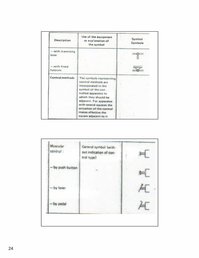
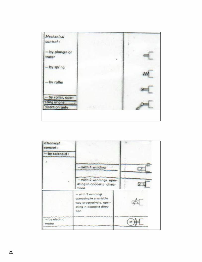
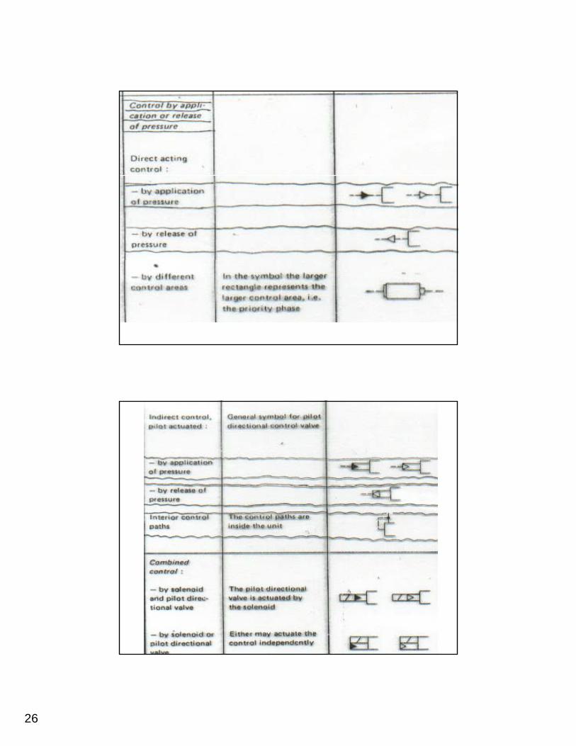
1 PNEUMATIC & HYDRAULIC SYSTEMS CHAPTER SIX PNEUMATIC SYSTEM DESIGN AND DEVELOPMENT Dr. Ibrahim Naimi Symbols And Standards In Pneumatics The development of pneumatic systems is assisted by a uniform approach to the representation of h l dh i i h bl d the elements and the circuits. The symbols used for the individual elements must display the following characteristics: • Actuation and return actuation methods. • Number of connections. • Number of switching positions. • General operating principle. • Simplified representation of the flow path.
Transcript of PNEUMATIC & HYDRAULIC SYSTEMS and H Chapter 6.pdf · PNEUMATIC & HYDRAULIC SYSTEMS CHAPTER SIX...
1
PNEUMATIC & HYDRAULIC SYSTEMS
CHAPTER SIX
PNEUMATIC SYSTEM DESIGN AND DEVELOPMENT
Dr. Ibrahim Naimi
Symbols And Standards In Pneumatics
The development of pneumatic systems is assisted by a uniform approach to the representation of h l d h i i h b l dthe elements and the circuits. The symbols used
for the individual elements must display the following characteristics:
• Actuation and return actuation methods.• Number of connections.• Number of switching positions.• General operating principle.• Simplified representation of the flow path.
2
Symbols And Standards In Pneumatics
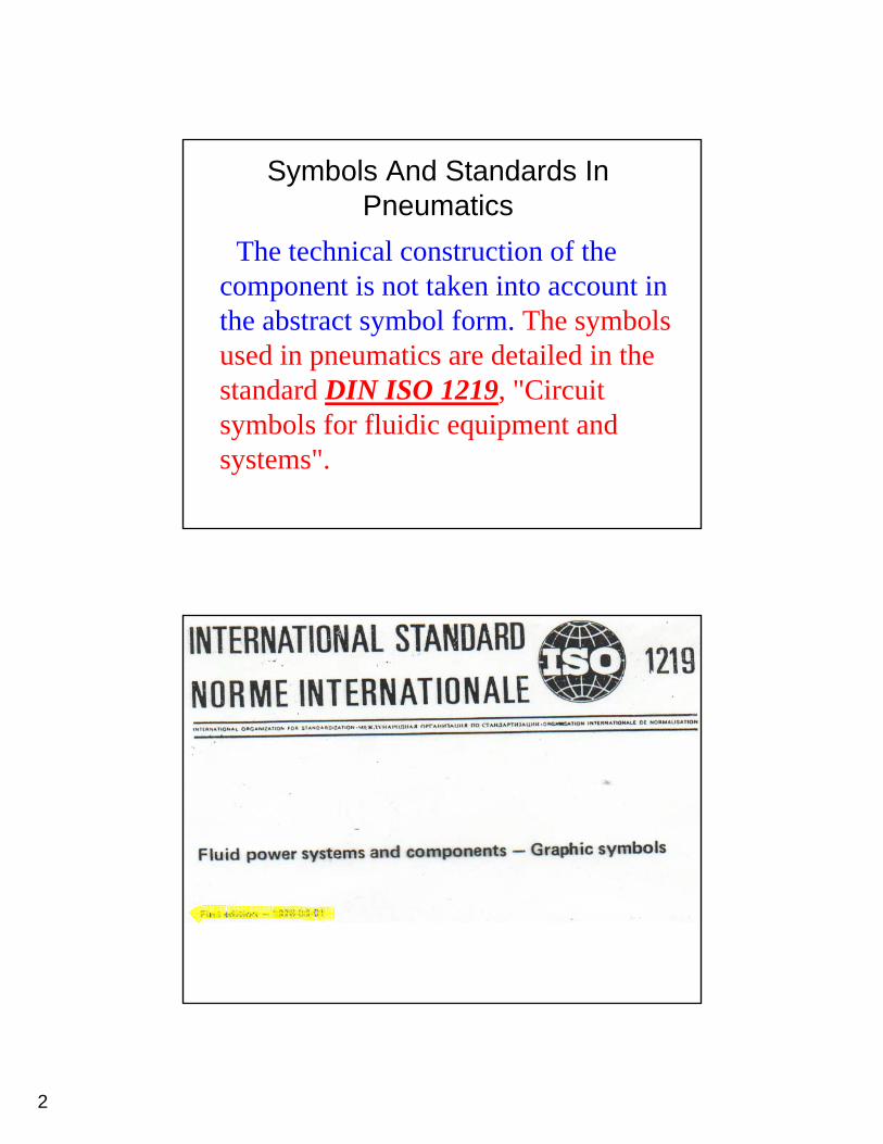
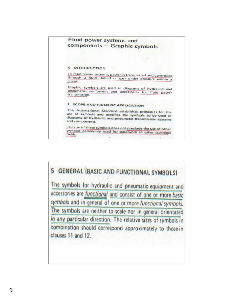
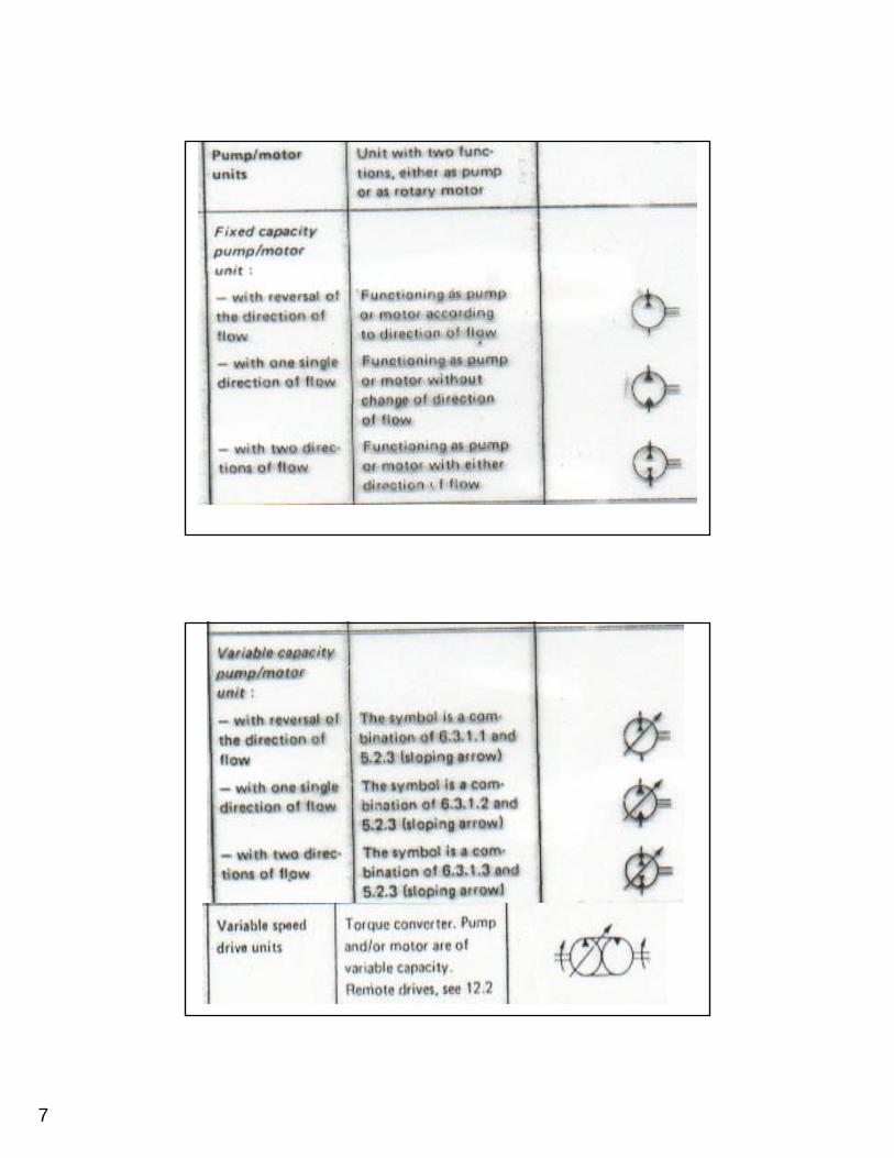
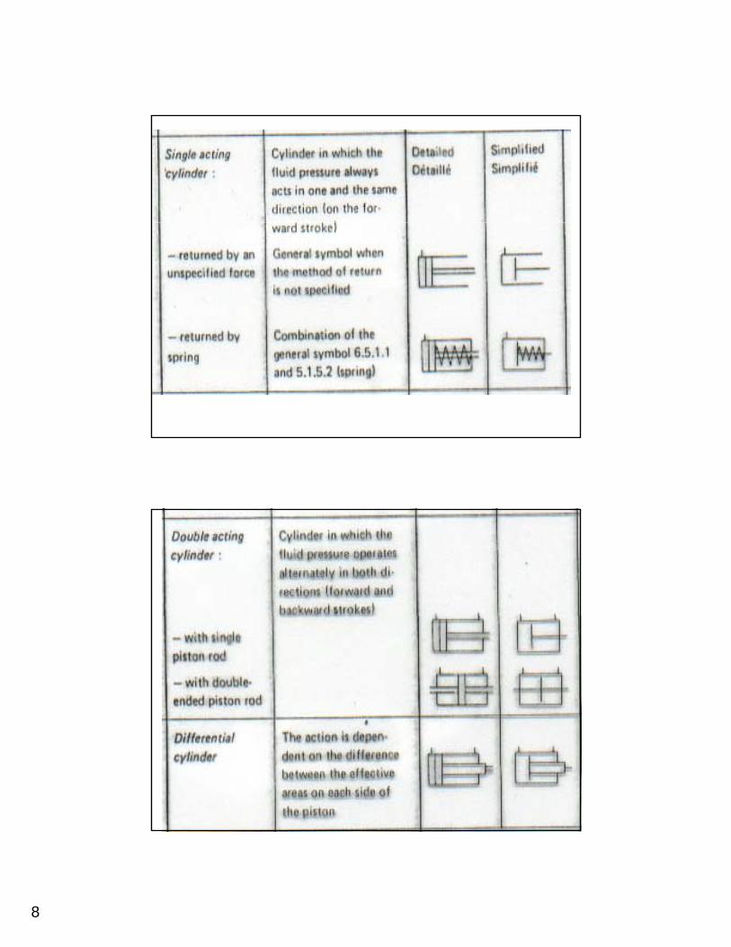
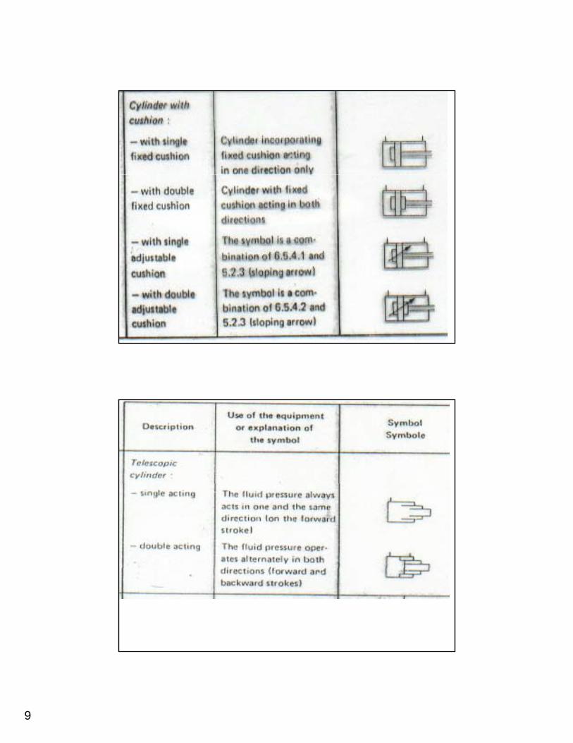
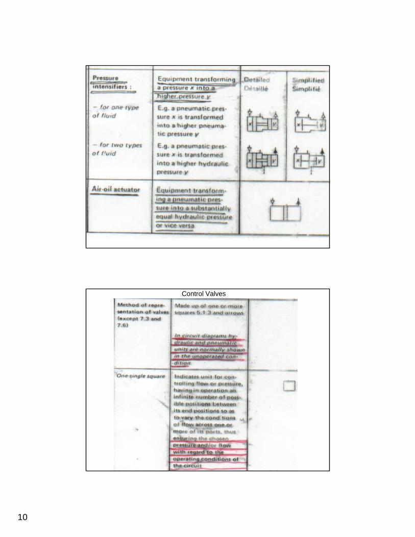
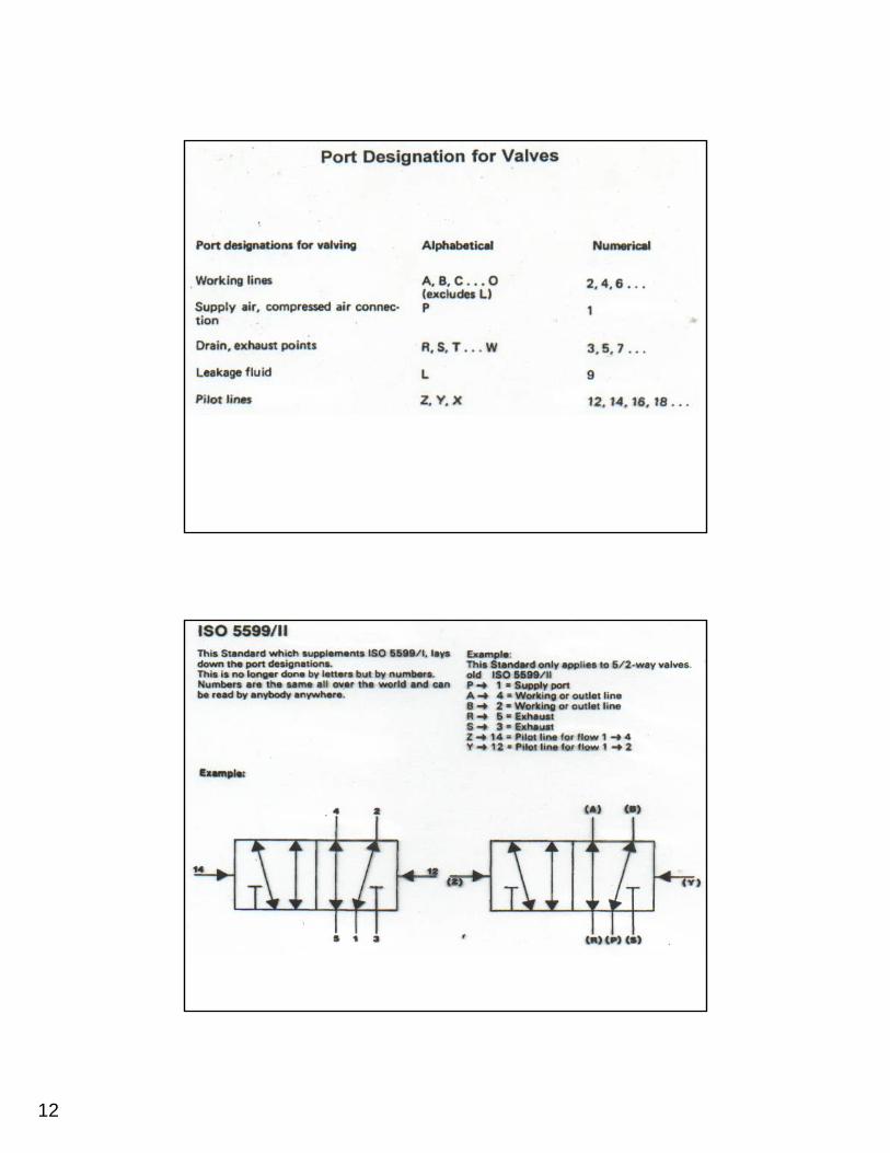
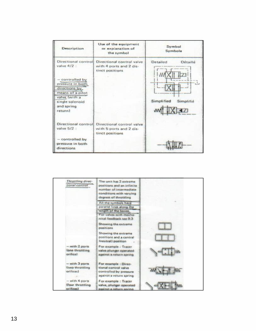
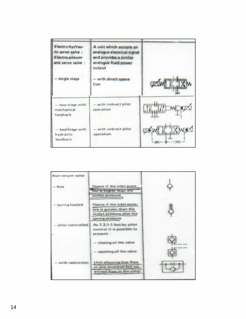
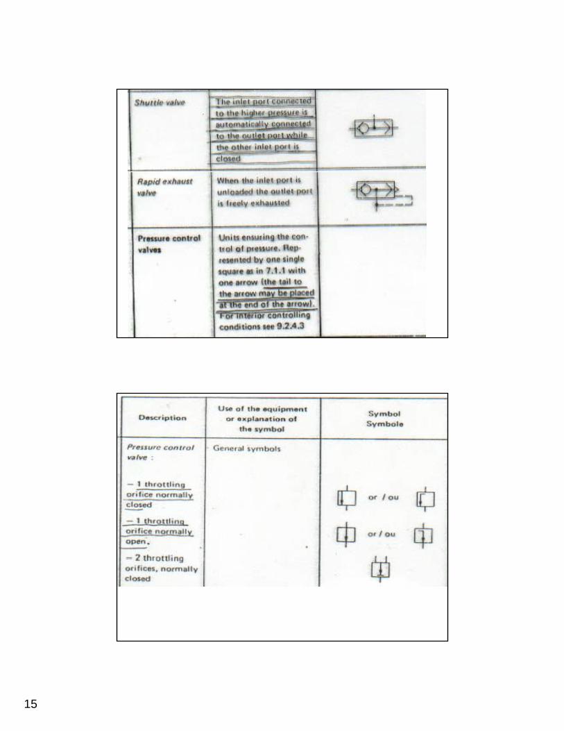
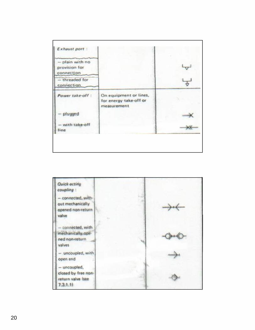
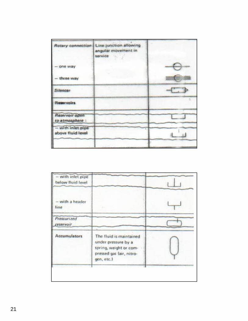
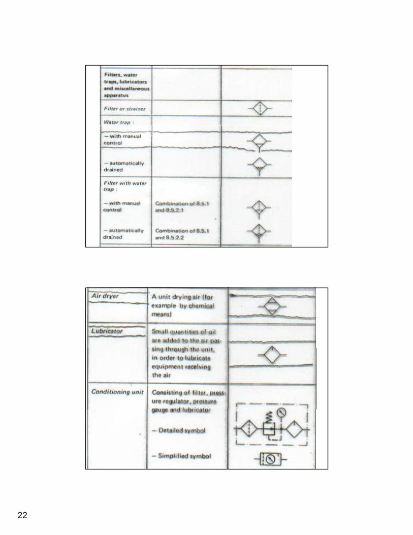
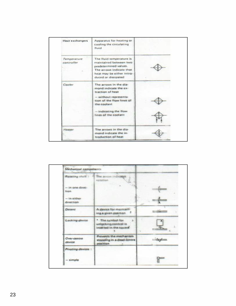
The technical construction of the component is not taken into account in the abstract symbol form. The symbols used in pneumatics are detailed in the standard DIN ISO 1219, "Circuitstandard DIN ISO 1219, Circuit symbols for fluidic equipment and systems".
3
4
5

6
7
8
9
10
Control Valves

11
12
13
14
15
16
17
18
19
20
21
22
23
24
25
26

27
28
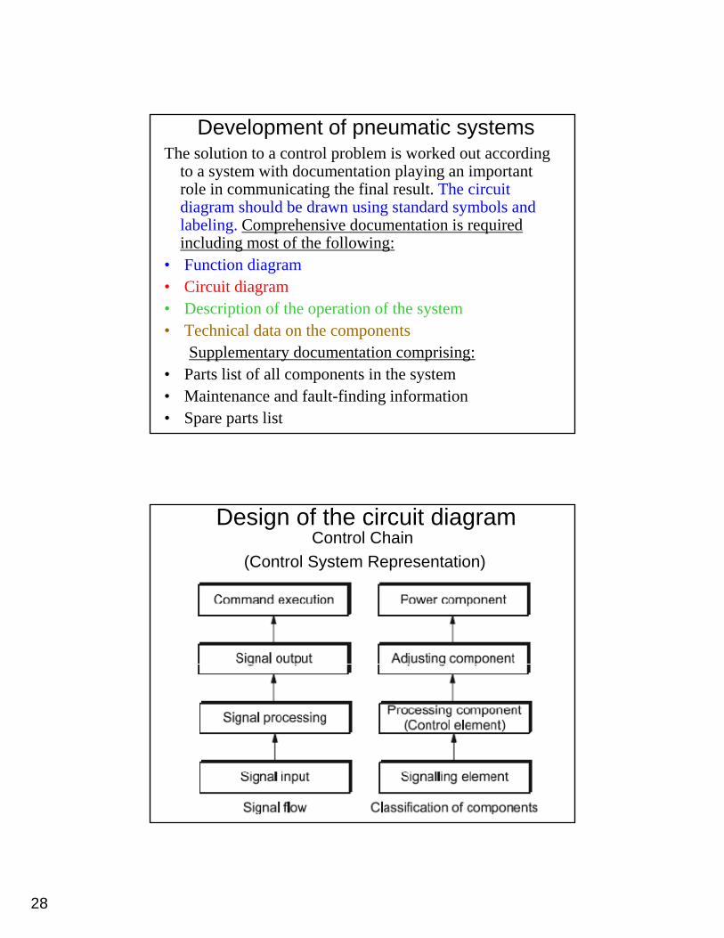
Development of pneumatic systemsThe solution to a control problem is worked out according
to a system with documentation playing an important role in communicating the final result. The circuit diagram should be drawn using standard symbols and l b li C h i d t ti i i dlabeling. Comprehensive documentation is required including most of the following:
• Function diagram• Circuit diagram• Description of the operation of the system
T h i l d t th t• Technical data on the componentsSupplementary documentation comprising:
• Parts list of all components in the system• Maintenance and fault-finding information• Spare parts list
Design of the circuit diagramControl Chain
(Control System Representation)
29
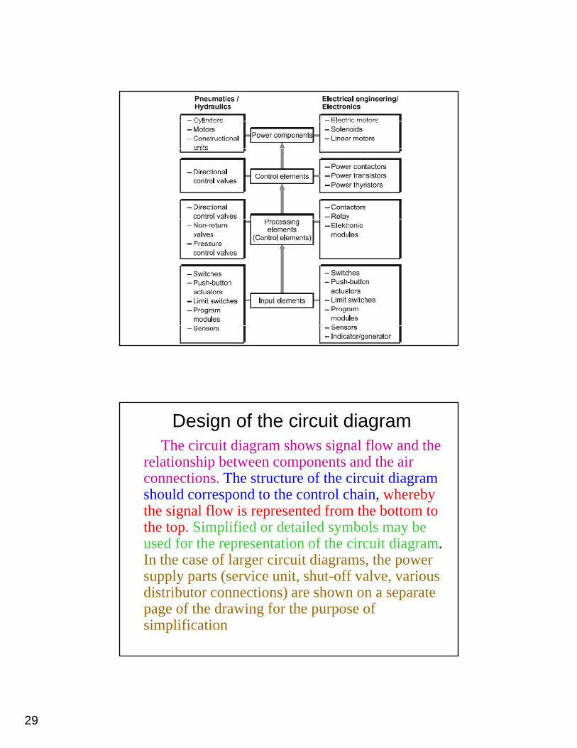
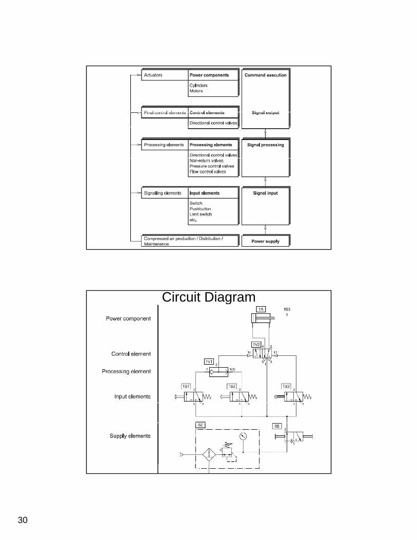
Design of the circuit diagramThe circuit diagram shows signal flow and the
relationship between components and the air connections. The structure of the circuit diagram should correspond to the control chain, whereby the signal flow is represented from the bottom to the top. Simplified or detailed symbols may be used for the representation of the circuit diagram. In the case of larger circuit diagrams, the power
l ( i i h ff l isupply parts (service unit, shut-off valve, various distributor connections) are shown on a separate page of the drawing for the purpose of simplification
30
Circuit Diagram
31
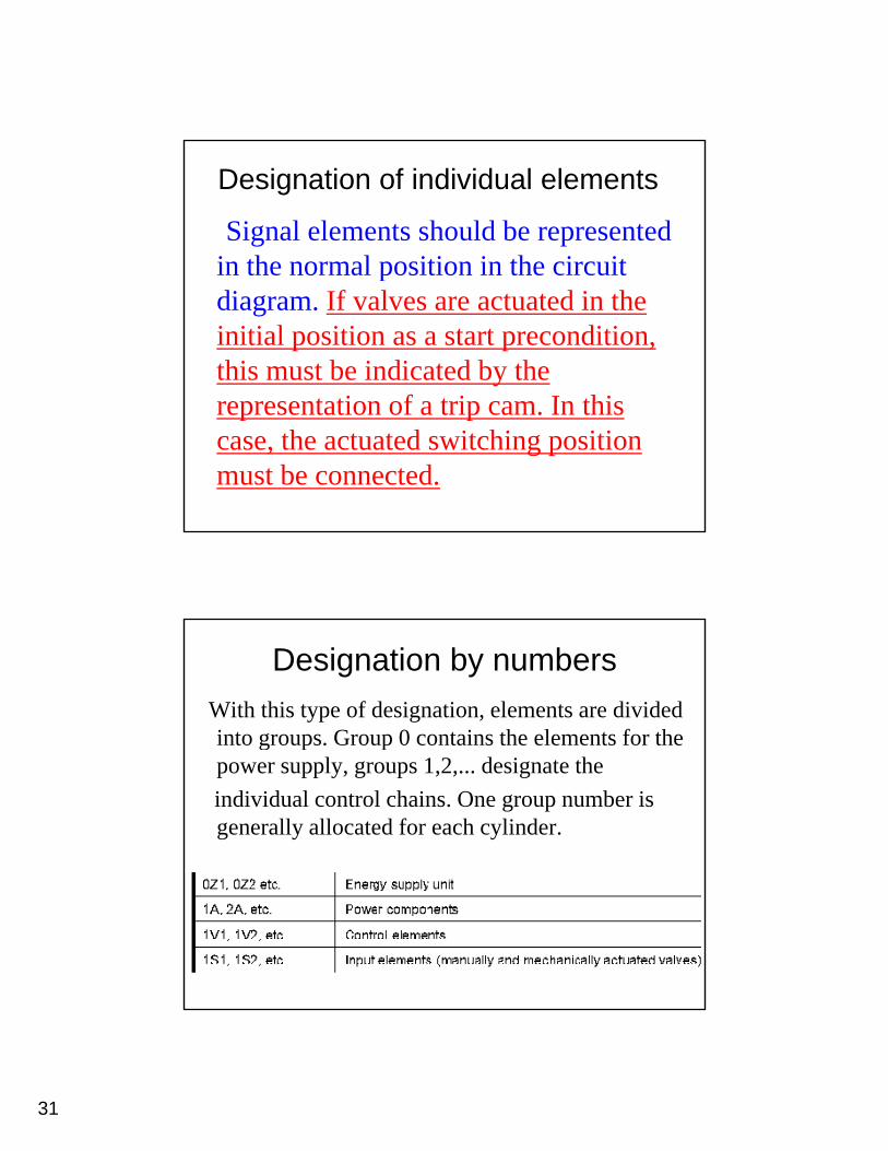
Designation of individual elements
Signal elements should be represented in the normal position in the circuitin the normal position in the circuit diagram. If valves are actuated in the initial position as a start precondition, this must be indicated by the representation of a trip cam In thisrepresentation of a trip cam. In this case, the actuated switching position must be connected.
Designation by numbersWith this type of designation, elements are divided into groups. Group 0 contains the elements for the g p ppower supply, groups 1,2,... designate theindividual control chains. One group number is generally allocated for each cylinder.
32
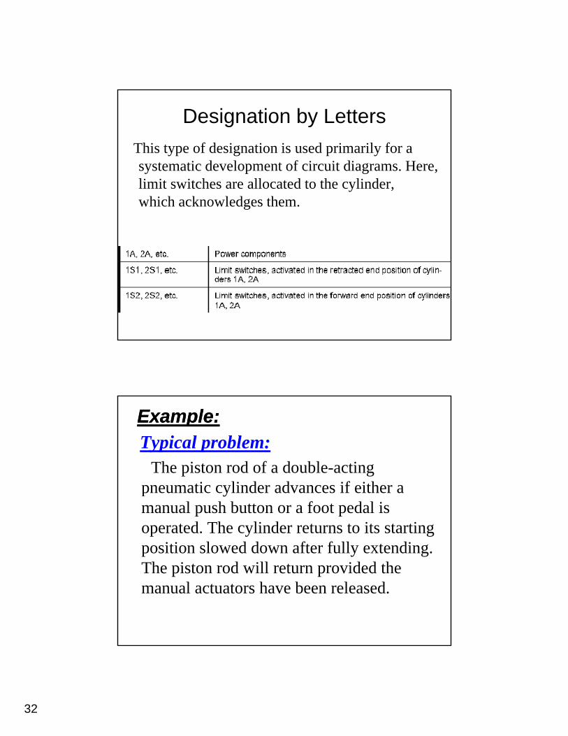
Designation by LettersThis type of designation is used primarily for a systematic development of circuit diagrams. Here, y p g ,limit switches are allocated to the cylinder, which acknowledges them.
Example:Example:Typical problem:
The piston rod of a double-acting pneumatic cylinder advances if either a manual push button or a foot pedal is operated. The cylinder returns to its starting position slowed down after fully extending. Th i d ill id d hThe piston rod will return provided the manual actuators have been released.
33
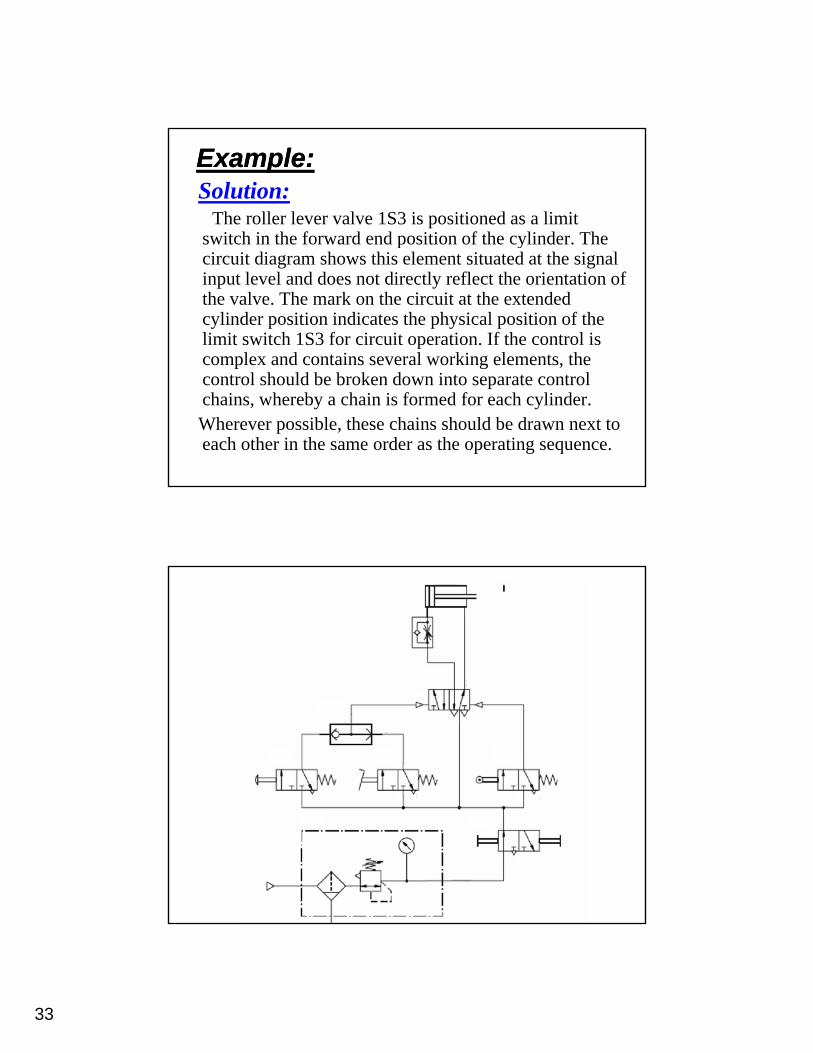
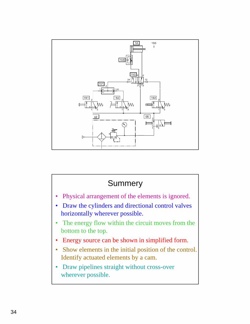
Example:Example:Solution:
The roller lever valve 1S3 is positioned as a limit switch in the forward end position of the cylinder. The p ycircuit diagram shows this element situated at the signal input level and does not directly reflect the orientation of the valve. The mark on the circuit at the extended cylinder position indicates the physical position of the limit switch 1S3 for circuit operation. If the control is complex and contains several working elements, the p g ,control should be broken down into separate control chains, whereby a chain is formed for each cylinder.Wherever possible, these chains should be drawn next to each other in the same order as the operating sequence.
34
Summery• Physical arrangement of the elements is ignored.• Draw the cylinders and directional control valves
horizontally wherever possible.• The energy flow within the circuit moves from the
bottom to the top.• Energy source can be shown in simplified form.
Sh l i h i i i l i i f h l• Show elements in the initial position of the control. Identify actuated elements by a cam.
• Draw pipelines straight without cross-over wherever possible.
35
Control System DevelopmentThe development of the control system solution requires that the problem is defined clearly. There are many ways of representing the problem in a descriptive or graphical form. The methods of representing the control problem include:
• Positional sketch• Motion diagram:
- Displacement-Step Diagram.- Displacement-Time Diagram.Displacement Time Diagram.
• Control chart• Function diagram• Function chart• Circuit diagram
Positional sketch
The positional sketch shows the relationship between the actuators and the machine fixture. The actuators are shown in the correct orientation. The positional sketch is not normally to scale and should not be too detailed. The diagram will be used in conjunction with the description of the machine operation and the motion diagrams.
36
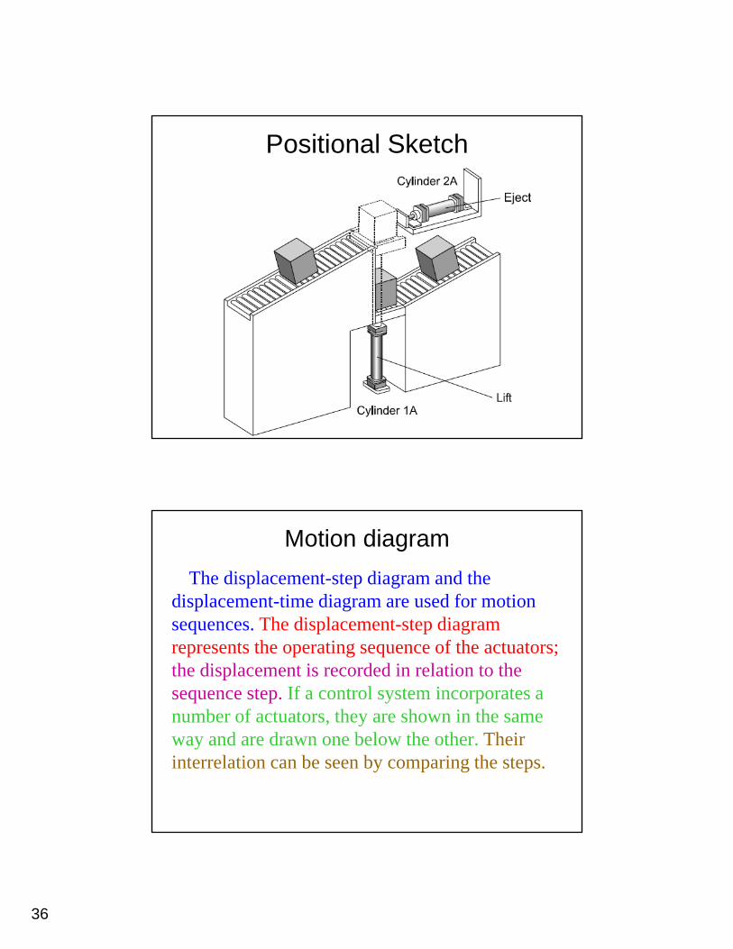
Positional Sketch
Motion diagramThe displacement-step diagram and the
displacement-time diagram are used for motion h di l disequences. The displacement-step diagram
represents the operating sequence of the actuators;the displacement is recorded in relation to the sequence step. If a control system incorporates a number of actuators, they are shown in the same , yway and are drawn one below the other. Their interrelation can be seen by comparing the steps.
37
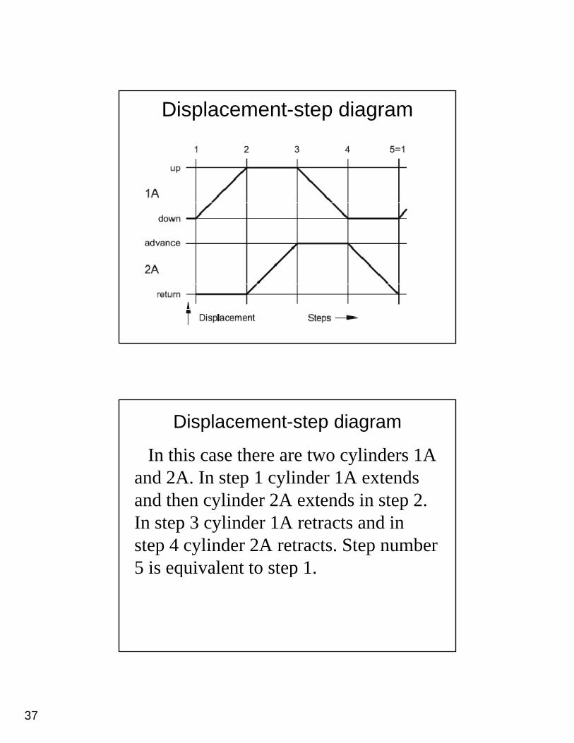
Displacement-step diagram
Displacement-step diagram
In this case there are two cylinders 1A and 2A. In step 1 cylinder 1A extendsand 2A. In step 1 cylinder 1A extends and then cylinder 2A extends in step 2. In step 3 cylinder 1A retracts and in step 4 cylinder 2A retracts. Step number 5 is equivalent to step 15 is equivalent to step 1.
38
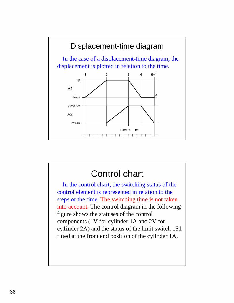
Displacement-time diagramIn the case of a displacement-time diagram, the
displacement is plotted in relation to the time.
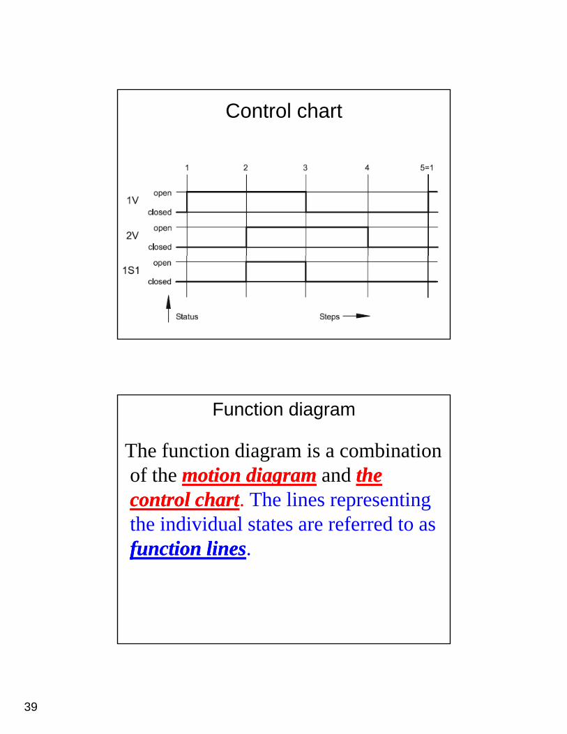
Control chartIn the control chart, the switching status of the
control element is represented in relation to the h i h i hi i i ksteps or the time. The switching time is not taken
into account. The control diagram in the following figure shows the statuses of the control components (1V for cylinder 1A and 2V for cy1inder 2A) and the status of the limit switch 1S1 y )fitted at the front end position of the cylinder 1A.
39
Control chart
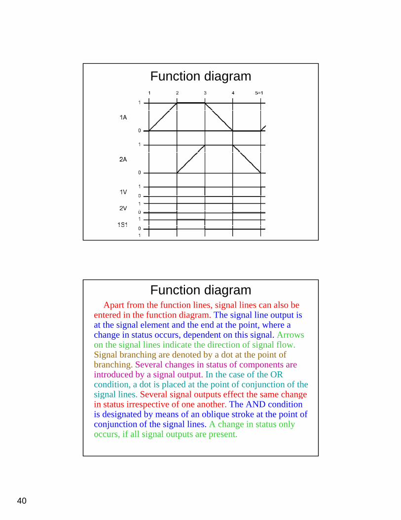
Function diagram
The function diagram is a combinationof the motion diagrammotion diagram and thetheof the motion diagrammotion diagram and the the control chartcontrol chart. The lines representing the individual states are referred to as function linesfunction lines.
40
Function diagram
Function diagramApart from the function lines, signal lines can also be
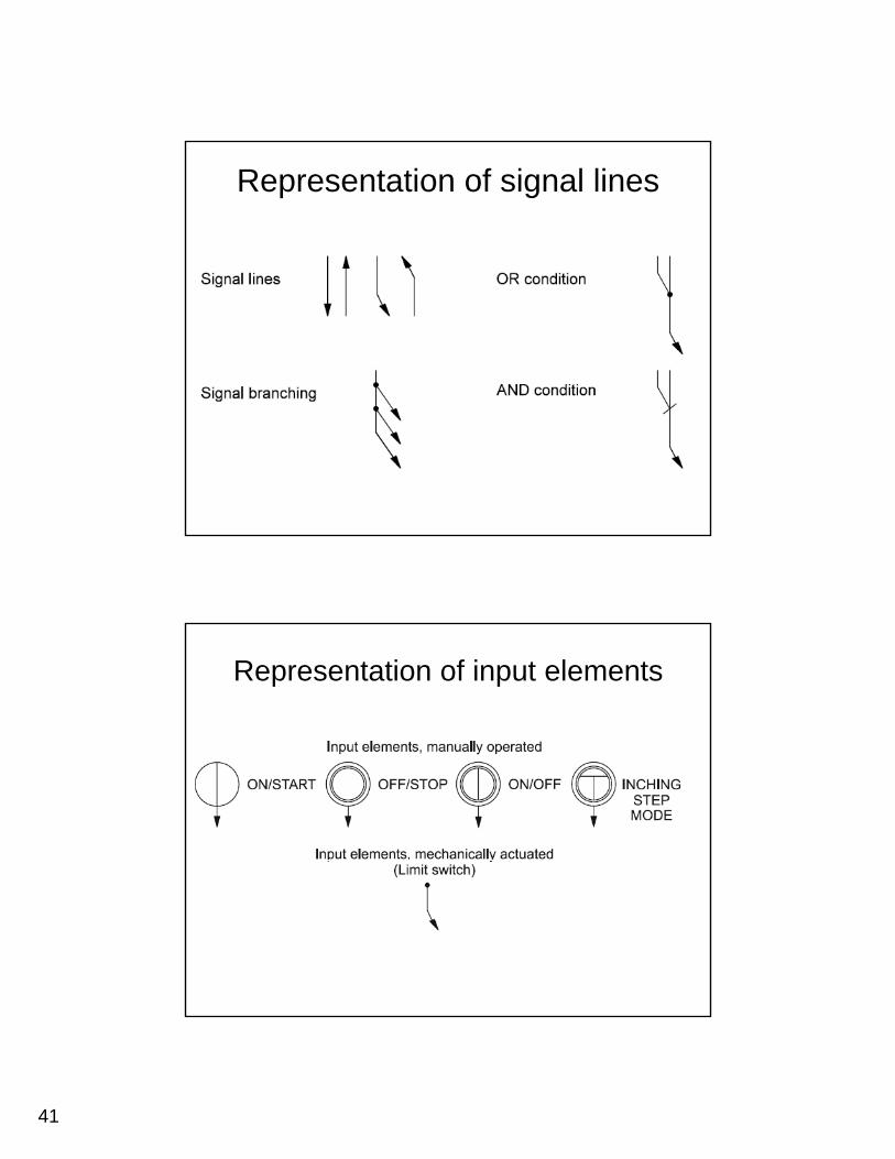
entered in the function diagram. The signal line output is at the signal element and the end at the point, where a change in status occurs, dependent on this signal. Arrows g , p gon the signal lines indicate the direction of signal flow.Signal branching are denoted by a dot at the point of branching. Several changes in status of components are introduced by a signal output. In the case of the OR condition, a dot is placed at the point of conjunction of the signal lines. Several signal outputs effect the same change g g p gin status irrespective of one another. The AND condition is designated by means of an oblique stroke at the point of conjunction of the signal lines. A change in status only occurs, if all signal outputs are present.
41
Representation of signal lines
Representation of input elements
42
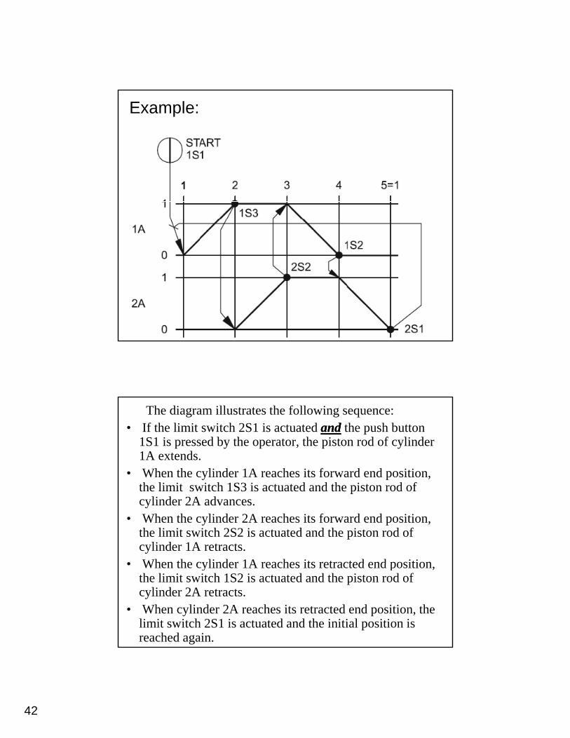
Example:
The diagram illustrates the following sequence:• If the limit switch 2S1 is actuated andand the push button
1S1 is pressed by the operator, the piston rod of cylinder 1A extends.
• When the cylinder 1A reaches its forward end position, the limit switch 1S3 is actuated and the piston rod of cylinder 2A advances.
• When the cylinder 2A reaches its forward end position, the limit switch 2S2 is actuated and the piston rod of cylinder 1A retracts.
• When the cylinder 1A reaches its retracted end position• When the cylinder 1A reaches its retracted end position, the limit switch 1S2 is actuated and the piston rod of cylinder 2A retracts.
• When cylinder 2A reaches its retracted end position, the limit switch 2S1 is actuated and the initial position is reached again.
43
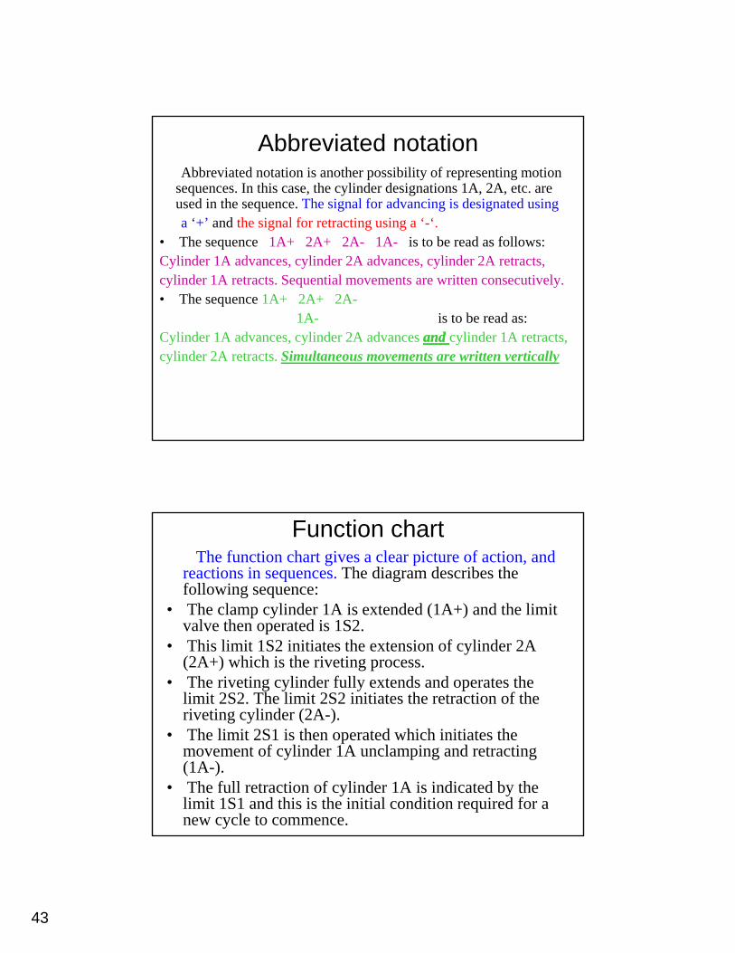
Abbreviated notationAbbreviated notation is another possibility of representing motion
sequences. In this case, the cylinder designations 1A, 2A, etc. are used in the sequence. The signal for advancing is designated using a ‘+’ and the signal for retracting using a ‘-‘a + and the signal for retracting using a - .
• The sequence 1A+ 2A+ 2A- 1A- is to be read as follows:Cylinder 1A advances, cylinder 2A advances, cylinder 2A retracts,cylinder 1A retracts. Sequential movements are written consecutively.• The sequence 1A+ 2A+ 2A-
1A- is to be read as:C li d 1A d li d 2A d dd li d 1ACylinder 1A advances, cylinder 2A advances and and cylinder 1A retracts,cylinder 2A retracts. Simultaneous movements are written vertically
Function chartThe function chart gives a clear picture of action, and
reactions in sequences. The diagram describes the following sequence:
• The clamp cylinder 1A is extended (1A+) and the limit l h d i 1S2valve then operated is 1S2.
• This limit 1S2 initiates the extension of cylinder 2A (2A+) which is the riveting process.
• The riveting cylinder fully extends and operates the limit 2S2. The limit 2S2 initiates the retraction of the riveting cylinder (2A-).
• The limit 2S1 is then operated which initiates the movement of cylinder 1A unclamping and retracting (1A-).
• The full retraction of cylinder 1A is indicated by the limit 1S1 and this is the initial condition required for a new cycle to commence.
44
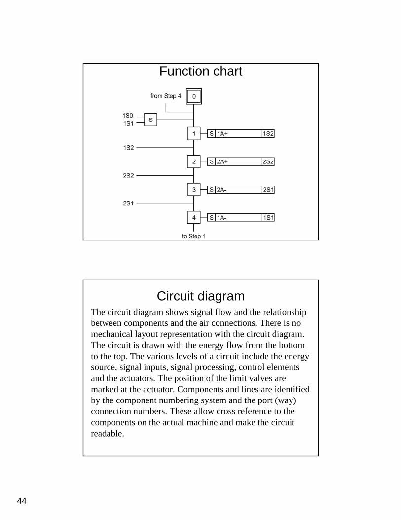
Function chart
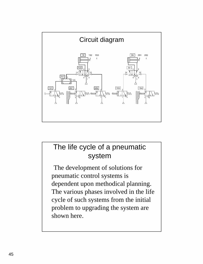
Circuit diagramThe circuit diagram shows signal flow and the relationship between components and the air connections. There is no mechanical layout representation with the circuit diagram. y p gThe circuit is drawn with the energy flow from the bottom to the top. The various levels of a circuit include the energy source, signal inputs, signal processing, control elements and the actuators. The position of the limit valves are marked at the actuator. Components and lines are identified b h b i d h ( )by the component numbering system and the port (way) connection numbers. These allow cross reference to the components on the actual machine and make the circuit readable.
45
Circuit diagram
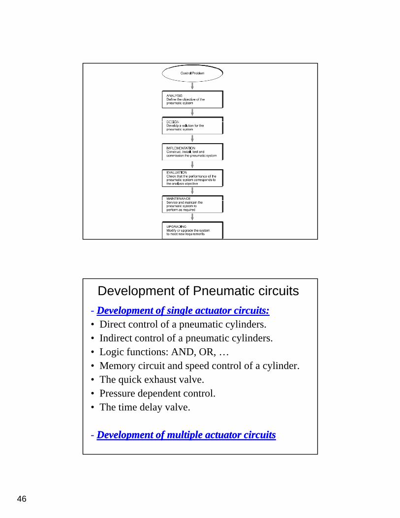
The life cycle of a pneumatic system
The development of solutions for pneumatic control systems is dependent upon methodical planning. The various phases involved in the life cycle of such systems from the initialcycle of such systems from the initial problem to upgrading the system are shown here.
46
Development of Pneumatic circuits- Development of single actuator circuits:Development of single actuator circuits:• Direct control of a pneumatic cylinders.• Indirect control of a pneumatic cylinders• Indirect control of a pneumatic cylinders.• Logic functions: AND, OR, …• Memory circuit and speed control of a cylinder.• The quick exhaust valve.• Pressure dependent control.Pressure dependent control.• The time delay valve.
- Development of multiple actuator circuitsDevelopment of multiple actuator circuits
47
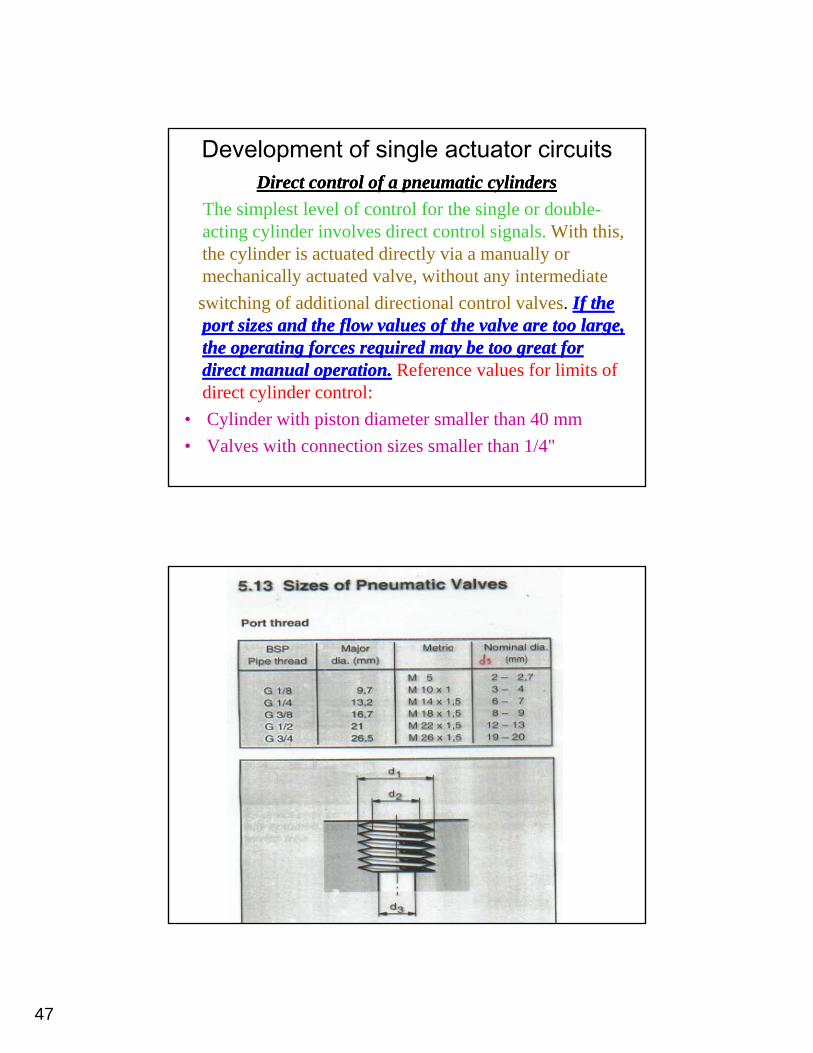
Development of single actuator circuitsDirect control of a pneumatic cylindersDirect control of a pneumatic cylinders
The simplest level of control for the single or double-acting cylinder involves direct control signals. With this, h li d i d di l i llthe cylinder is actuated directly via a manually or
mechanically actuated valve, without any intermediateswitching of additional directional control valves. If the If the port sizes and the flow values of the valve are too large, port sizes and the flow values of the valve are too large, the operating forces required may be too great for the operating forces required may be too great for di t l tidi t l ti Reference al es for limits ofdirect manual operation.direct manual operation. Reference values for limits of direct cylinder control:
• Cylinder with piston diameter smaller than 40 mm• Valves with connection sizes smaller than 1/4"
48
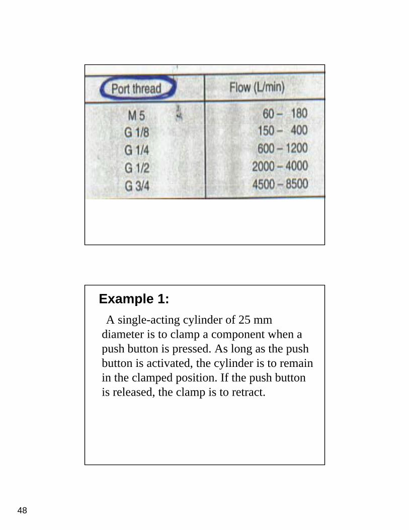
Example 1:A single-acting cylinder of 25 mm
diameter is to clamp a component when a h b i d A l h hpush button is pressed. As long as the push
button is activated, the cylinder is to remain in the clamped position. If the push button is released, the clamp is to retract.
49
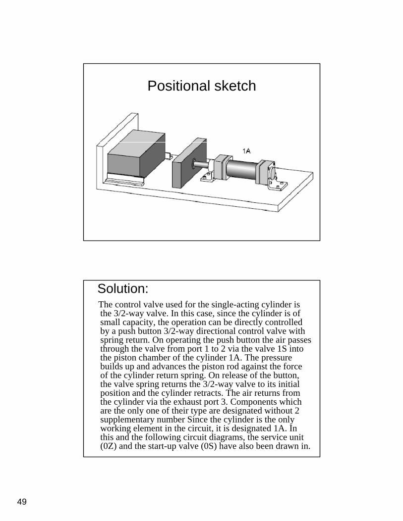
Positional sketch
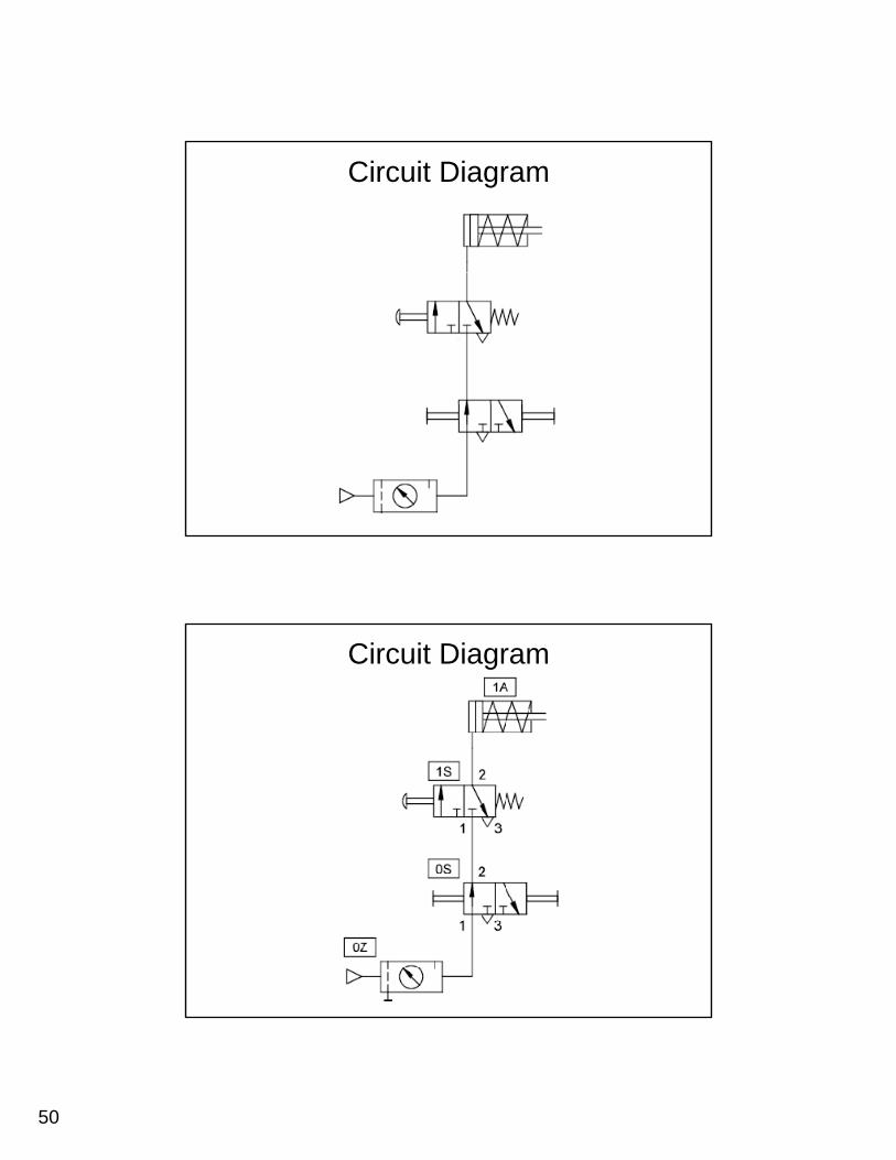
Solution:The control valve used for the single-acting cylinder is the 3/2-way valve. In this case, since the cylinder is of small capacity, the operation can be directly controlled by a push button 3/2-way directional control valve with spring return On operating the push button the air passesspring return. On operating the push button the air passes through the valve from port 1 to 2 via the valve 1S into the piston chamber of the cylinder 1A. The pressure builds up and advances the piston rod against the force of the cylinder return spring. On release of the button, the valve spring returns the 3/2-way valve to its initial position and the cylinder retracts. The air returns from the cylinder via the exhaust port 3. Components which are the only one of their type are designated without 2 supplementary number Since the cylinder is the only working element in the circuit, it is designated 1A. In this and the following circuit diagrams, the service unit (0Z) and the start-up valve (0S) have also been drawn in.
50
Circuit Diagram
Circuit Diagram
51
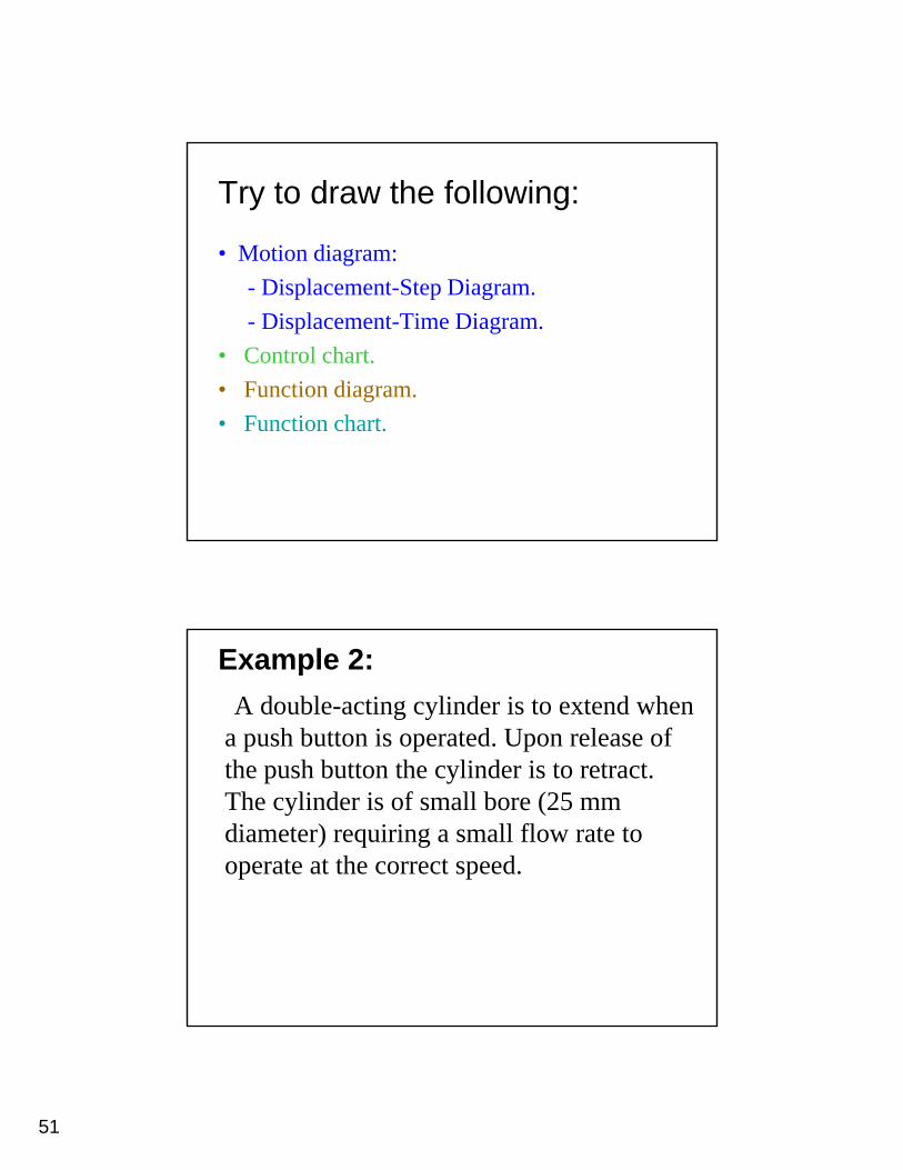
Try to draw the following:
• Motion diagram: - Displacement-Step Diagram.- Displacement-Time Diagram.
• Control chart.• Function diagram.• Function chart.
Example 2:A double-acting cylinder is to extend when
a push button is operated. Upon release of h h b h li d ithe push button the cylinder is to retract.
The cylinder is of small bore (25 mm diameter) requiring a small flow rate to operate at the correct speed.
52
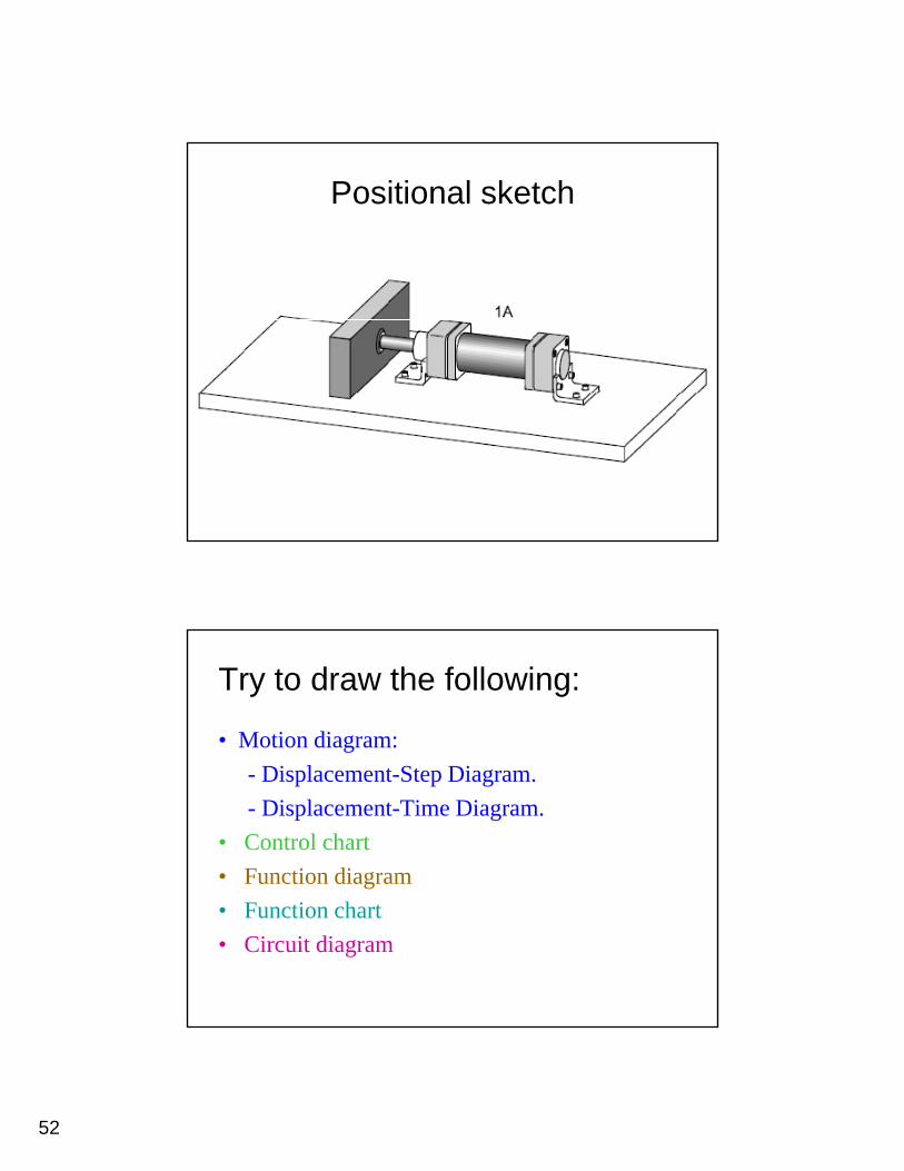
Positional sketch
Try to draw the following:
• Motion diagram: - Displacement-Step Diagram.- Displacement-Time Diagram.
• Control chart• Function diagram• Function chart• Circuit diagram
53
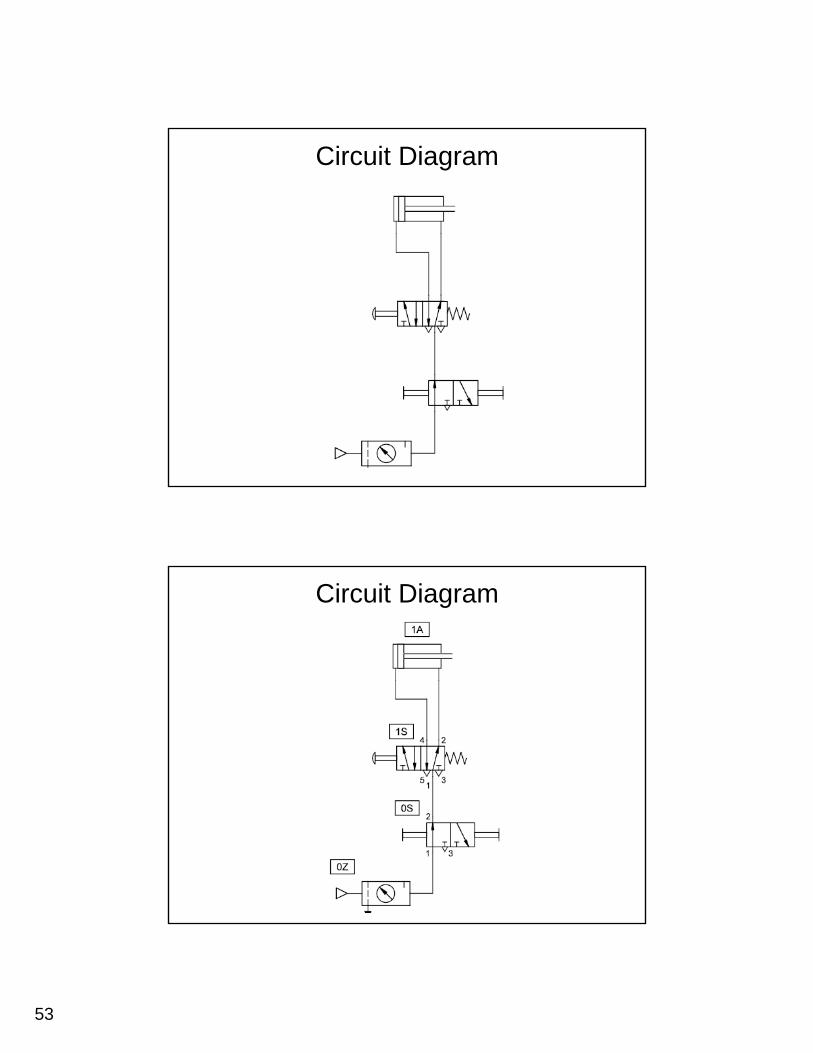
Circuit Diagram
Circuit Diagram
54
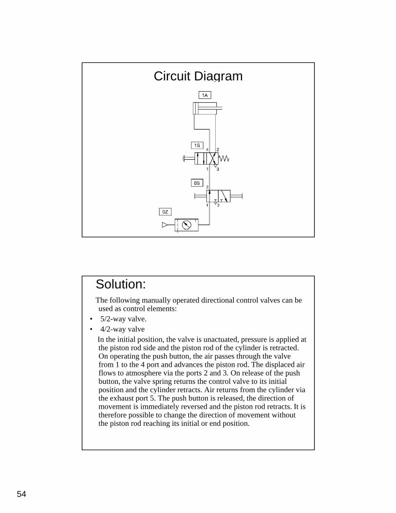
Circuit Diagram
Solution:The following manually operated directional control valves can be used as control elements:
• 5/2-way valve.• 4/2-way valve
In the initial position, the valve is unactuated, pressure is applied at the piston rod side and the piston rod of the cylinder is retracted. On operating the push button, the air passes through the valve from 1 to the 4 port and advances the piston rod. The displaced air flows to atmosphere via the ports 2 and 3. On release of the push button, the valve spring returns the control valve to its initial position and the cylinder retracts. Air returns from the cylinder viaposition and the cylinder retracts. Air returns from the cylinder via the exhaust port 5. The push button is released, the direction of movement is immediately reversed and the piston rod retracts. It is therefore possible to change the direction of movement without the piston rod reaching its initial or end position.
55
Indirect control of a pneumatic cylinderCylinders with a large piston diameter have a
high air requirement. A control element with high nominal flow rate must be used to actuate thesenominal flow rate must be used to actuate these.If the force should prove too high for a manual actuation of the valve, then an indirect actuation should be constructed, whereby a signal is generated via a second smaller valve, which will
id h f i h h lprovide the force necessary to switch the control element.
Example 3:A single-acting cylinder with a
large piston diameter is to clamp a g p pworkpiece following actuation of a push button. The cylinder is to retract once the push button is
l dreleased.
56
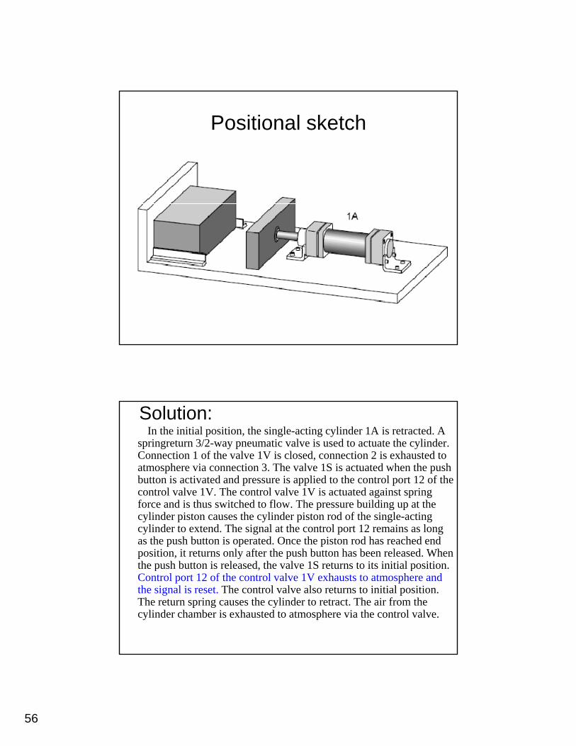
Positional sketch
Solution:In the initial position, the single-acting cylinder 1A is retracted. A
springreturn 3/2-way pneumatic valve is used to actuate the cylinder. Connection 1 of the valve 1V is closed, connection 2 is exhausted to atmosphere via connection 3. The valve 1S is actuated when the push button is activated and pressure is applied to the control port 12 of the p pp pcontrol valve 1V. The control valve 1V is actuated against spring force and is thus switched to flow. The pressure building up at the cylinder piston causes the cylinder piston rod of the single-acting cylinder to extend. The signal at the control port 12 remains as long as the push button is operated. Once the piston rod has reached end position, it returns only after the push button has been released. When the push button is released, the valve 1S returns to its initial position. p , pControl port 12 of the control valve 1V exhausts to atmosphere and the signal is reset. The control valve also returns to initial position. The return spring causes the cylinder to retract. The air from the cylinder chamber is exhausted to atmosphere via the control valve.
57
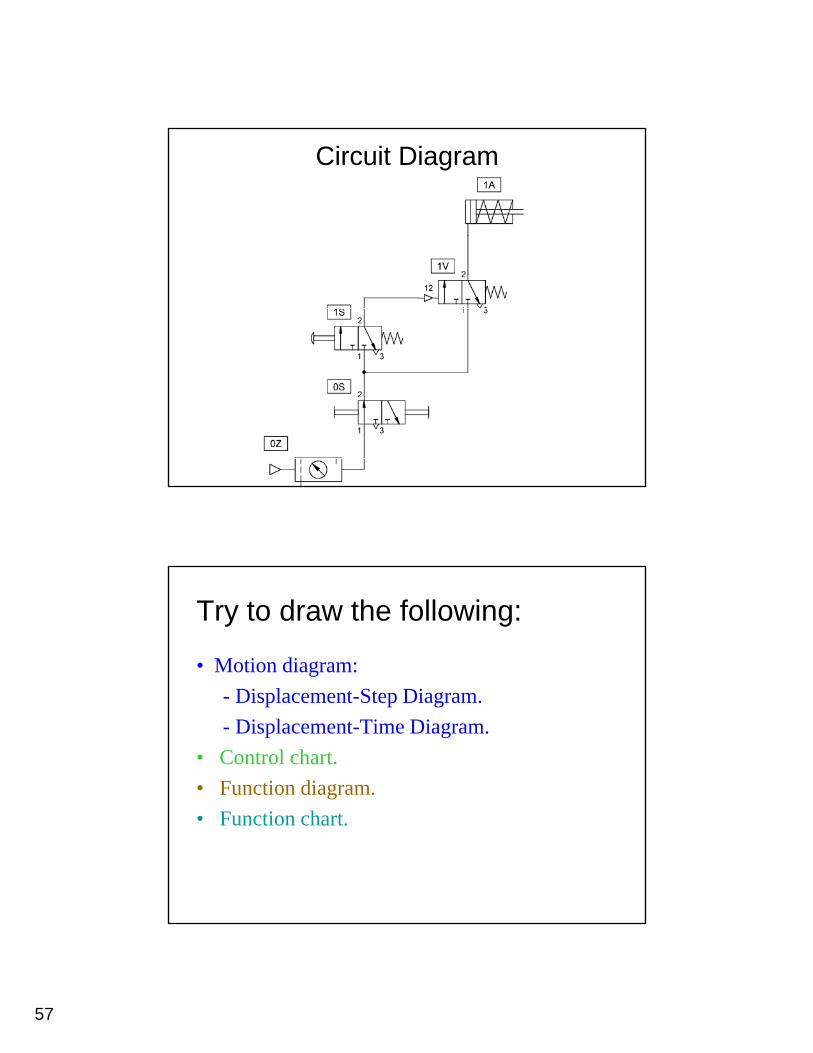
Circuit Diagram
Try to draw the following:
• Motion diagram: - Displacement-Step Diagram.- Displacement-Time Diagram.
• Control chart.• Function diagram.• Function chart.
58
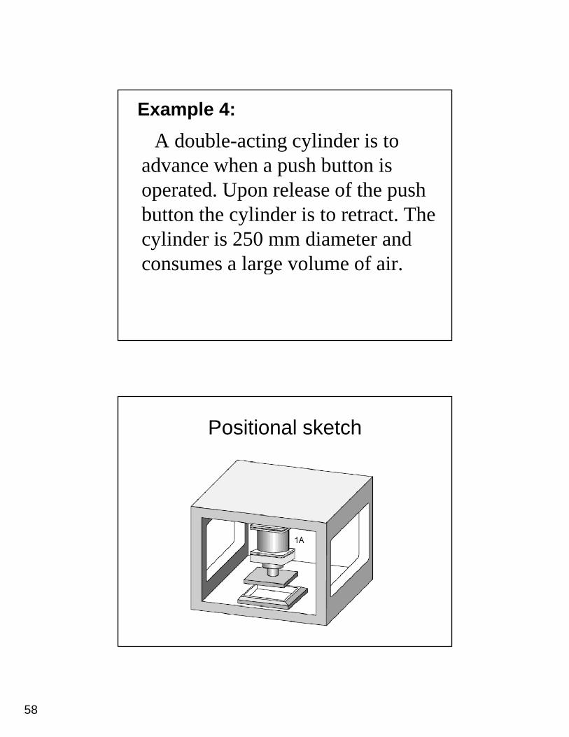
Example 4:A double-acting cylinder is to
advance when a push button is poperated. Upon release of the push button the cylinder is to retract. The cylinder is 250 mm diameter and
l l f iconsumes a large volume of air.
Positional sketch
59
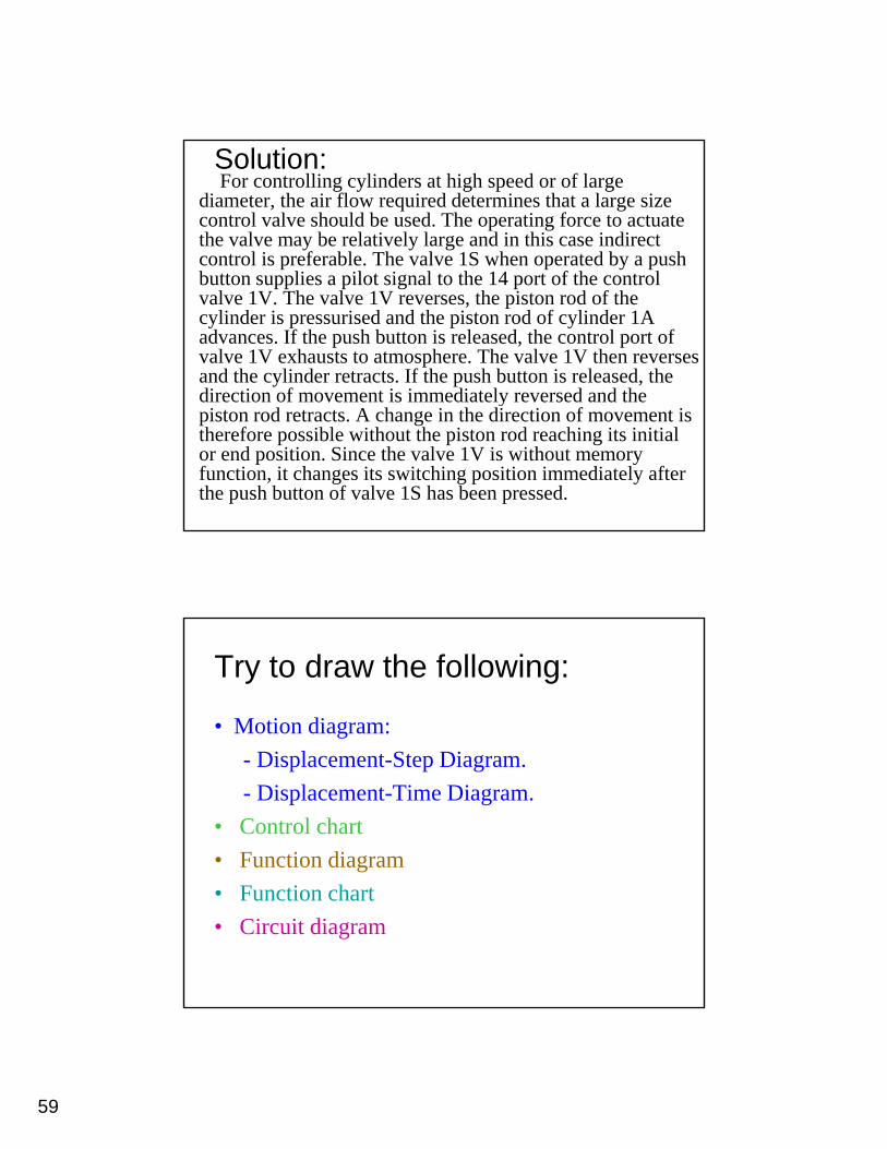
Solution:For controlling cylinders at high speed or of large
diameter, the air flow required determines that a large size control valve should be used. The operating force to actuate the valve may be relatively large and in this case indirect control is preferable. The valve 1S when operated by a push button supplies a pilot signal to the 14 port of the control valve 1V. The valve 1V reverses, the piston rod of the cylinder is pressurised and the piston rod of cylinder 1A advances. If the push button is released, the control port of valve 1V exhausts to atmosphere. The valve 1V then reverses and the cylinder retracts. If the push button is released, the direction of movement is immediately reversed and thedirection of movement is immediately reversed and the piston rod retracts. A change in the direction of movement is therefore possible without the piston rod reaching its initial or end position. Since the valve 1V is without memory function, it changes its switching position immediately after the push button of valve 1S has been pressed.
Try to draw the following:
• Motion diagram: - Displacement-Step Diagram.- Displacement-Time Diagram.
• Control chart• Function diagram• Function chart• Circuit diagram
60
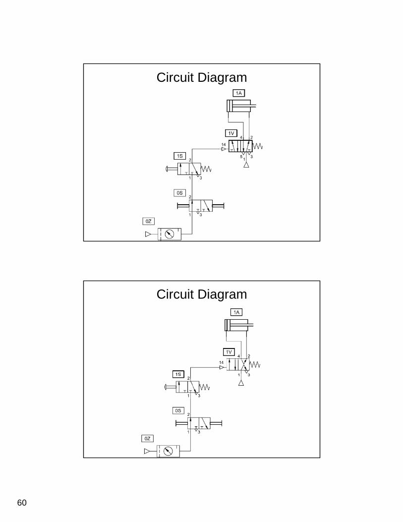
Circuit Diagram
Circuit Diagram
61
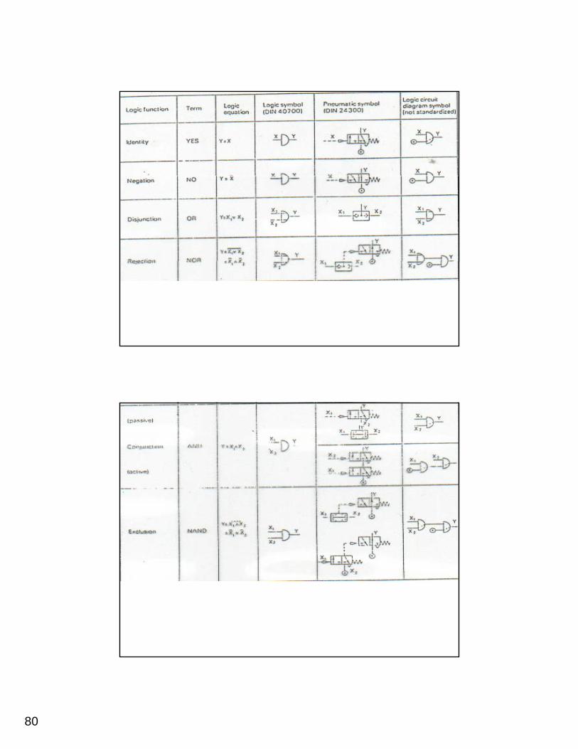
Logic FunctionsThe pneumatic shuttle valve and the dual pressure
valve have logic functions. Both have two inputs and one output each The shuttle valve has theand one output each. The shuttle valve has the characteristic of an OR function, whereby at least either of two inputs 1 or 1(3) are required to generate an output at port 2 of the valve. In the case of the dual pressure valve, the characteristic is h f h A f i h b b h i 1that of the AND function, whereby both inputs 1
and 1(3) are required to initiate an output 2.
Example 5:The piston rod of a double-acting
cylinder is to advance when the 3/2-yway roller lever valve 1S2 is actuated and the push button of the 3/2-way valve 1S1 is actuated. If either of these
l d h h li d iare released, then the cylinder is to return to the initial position.
62
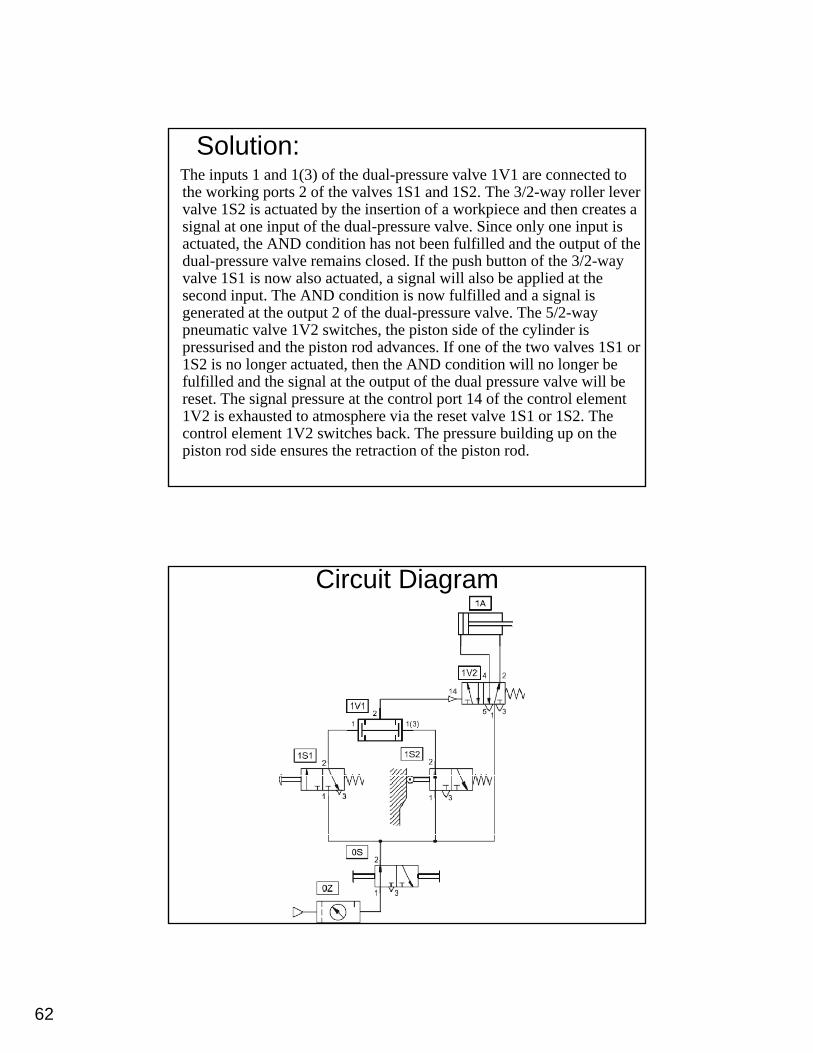
Solution:The inputs 1 and 1(3) of the dual-pressure valve 1V1 are connected to the working ports 2 of the valves 1S1 and 1S2. The 3/2-way roller lever valve 1S2 is actuated by the insertion of a workpiece and then creates a signal at one input of the dual-pressure valve. Since only one input is actuated, the AND condition has not been fulfilled and the output of theactuated, the AND condition has not been fulfilled and the output of the dual-pressure valve remains closed. If the push button of the 3/2-way valve 1S1 is now also actuated, a signal will also be applied at the second input. The AND condition is now fulfilled and a signal is generated at the output 2 of the dual-pressure valve. The 5/2-way pneumatic valve 1V2 switches, the piston side of the cylinder is pressurised and the piston rod advances. If one of the two valves 1S1 or 1S2 is no longer actuated then the AND condition will no longer be1S2 is no longer actuated, then the AND condition will no longer be fulfilled and the signal at the output of the dual pressure valve will be reset. The signal pressure at the control port 14 of the control element 1V2 is exhausted to atmosphere via the reset valve 1S1 or 1S2. The control element 1V2 switches back. The pressure building up on the piston rod side ensures the retraction of the piston rod.
Circuit Diagram
63
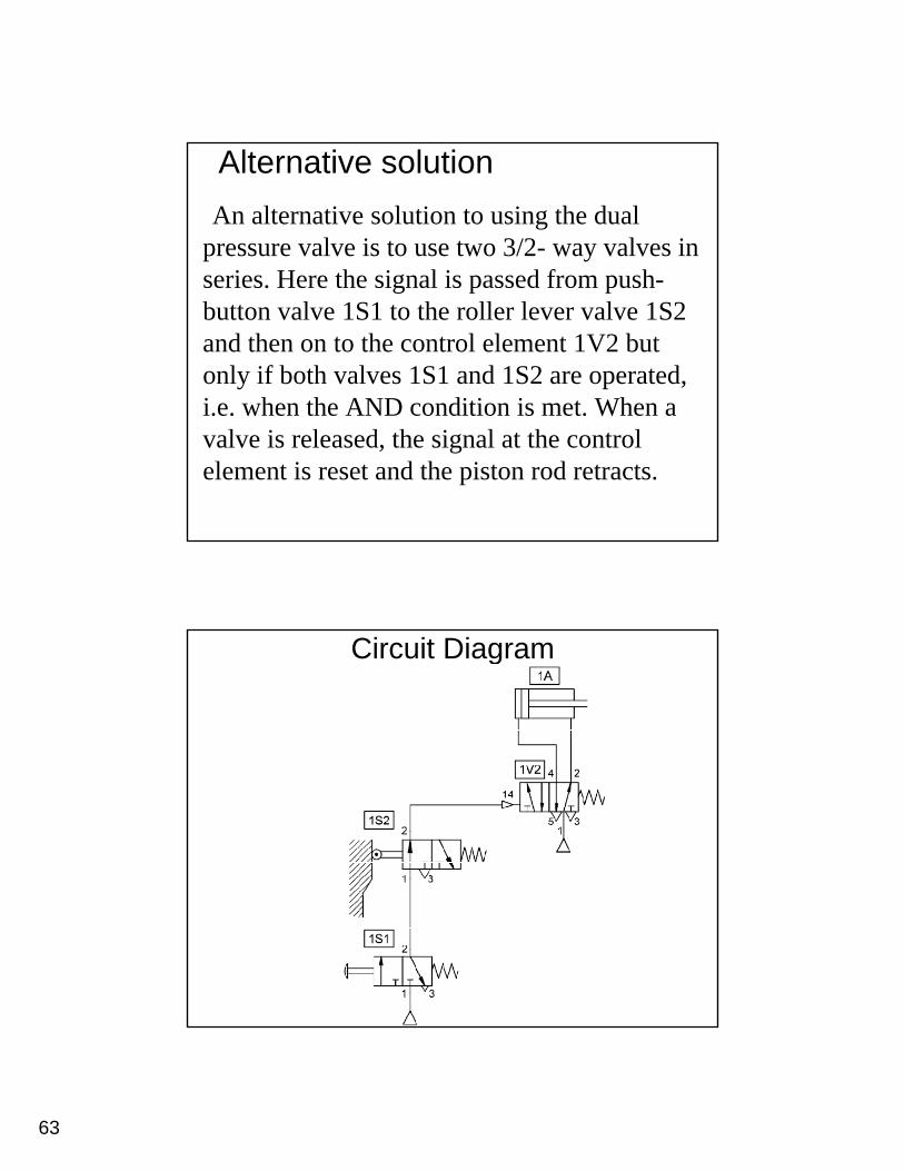
Alternative solutionAn alternative solution to using the dual
pressure valve is to use two 3/2- way valves in i H th i l i d f hseries. Here the signal is passed from push-
button valve 1S1 to the roller lever valve 1S2 and then on to the control element 1V2 but only if both valves 1S1 and 1S2 are operated, i e when the AND condition is met When ai.e. when the AND condition is met. When a valve is released, the signal at the control element is reset and the piston rod retracts.
Circuit Diagram
64
Try to draw the following:
• Motion diagram: - Displacement-Step Diagram.- Displacement-Time Diagram.
• Control chart.• Function diagram.• Function chart.
Example 6:The piston rod of the cylinder 1A is to
advance only if a workpiece is inserted in y pthe workpiece retainer, a guard has been lowered and the operator presses the push button valve. Upon the release of the push button or if the guard is no longer in itsbutton or if the guard is no longer in its lower position, the cylinder 1A is to retract to the initial position.
65
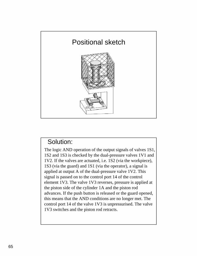
Positional sketch
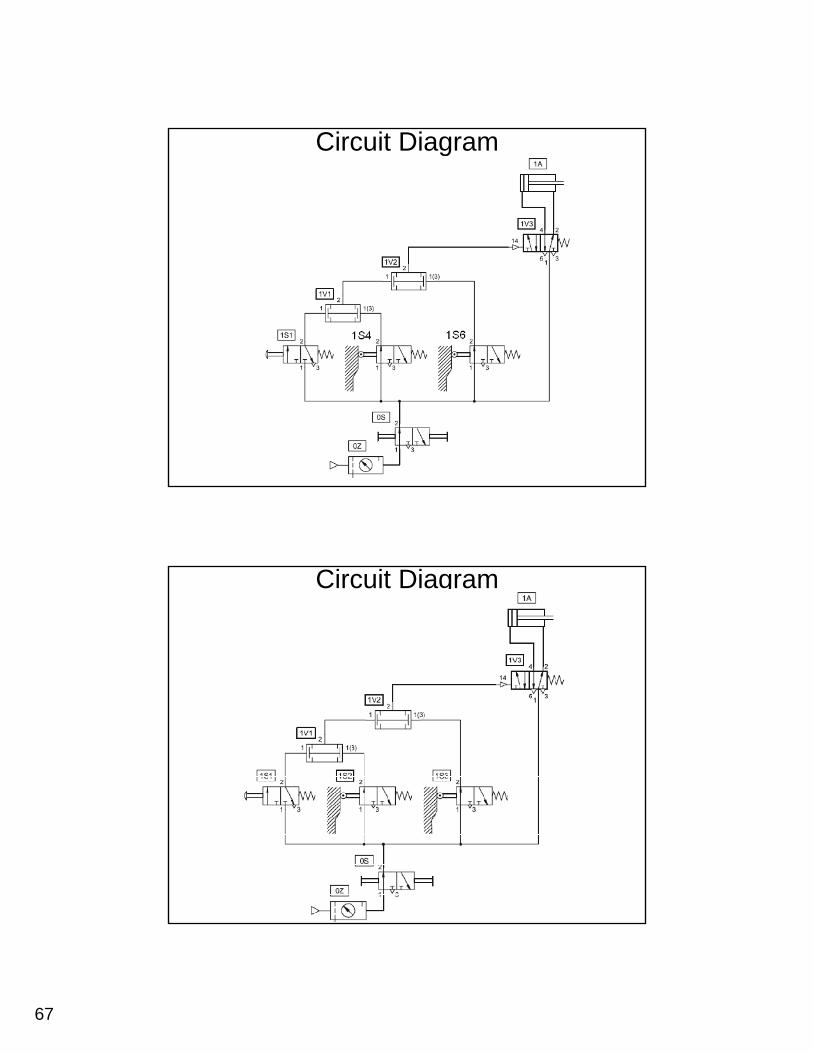
Solution:The logic AND operation of the output signals of valves 1S1, 1S2 and 1S3 is checked by the dual-pressure valves 1V1 and 1V2. If the valves are actuated, i.e. 1S2 (via the workpiece), 1S3 (via the guard) and 1S1 (via the operator) a signal is1S3 (via the guard) and 1S1 (via the operator), a signal is applied at output A of the dual-pressure valve 1V2. This signal is passed on to the control port 14 of the control element 1V3. The valve 1V3 reverses, pressure is applied at the piston side of the cylinder 1A and the piston rod advances. If the push button is released or the guard opened, this means that the AND conditions are no longer met. The control port 14 of the valve 1V3 is unpressurised. The valve 1V3 switches and the piston rod retracts.
66
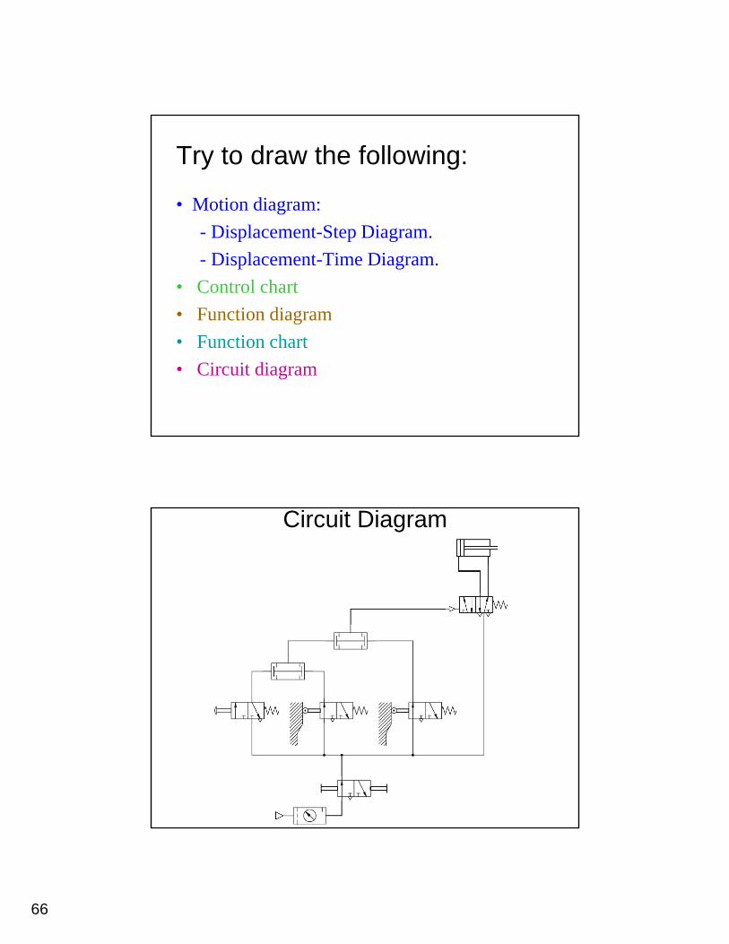
Try to draw the following:
• Motion diagram: - Displacement-Step Diagram.- Displacement-Time Diagram.
• Control chart• Function diagram• Function chart• Circuit diagram
Circuit Diagram
67
Circuit Diagram
Circuit Diagram
68
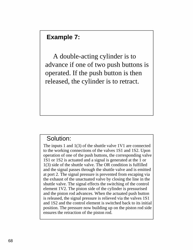
Example 7:
A double-acting cylinder is to g yadvance if one of two push buttons is operated. If the push button is then released, the cylinder is to retract.
Solution:The inputs 1 and 1(3) of the shuttle valve 1V1 are connected to the working connections of the valves 1S1 and 1S2. Upon operation of one of the push buttons, the corresponding valve 1S1 or 1S2 is actuated and a signal is generated at the 1 or 1(3) side of the shuttle valve. The OR condition is fulfilled and the signal passes through the shuttle valve and is emitted at port 2. The signal pressure is prevented from escaping via the exhaust of the unactuated valve by closing the line in the shuttle valve. The signal effects the switching of the control element 1V2. The piston side of the cylinder is pressurised and the piston rod advances. When the actuated push button is released, the signal pressure is relieved via the valves 1S1 and 1S2 and the control element is switched back to its initial position. The pressure now building up on the piston rod side ensures the retraction of the piston rod.
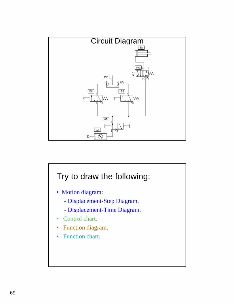
69
Circuit Diagram
Try to draw the following:
• Motion diagram: - Displacement-Step Diagram.- Displacement-Time Diagram.
• Control chart.• Function diagram.• Function chart.
70
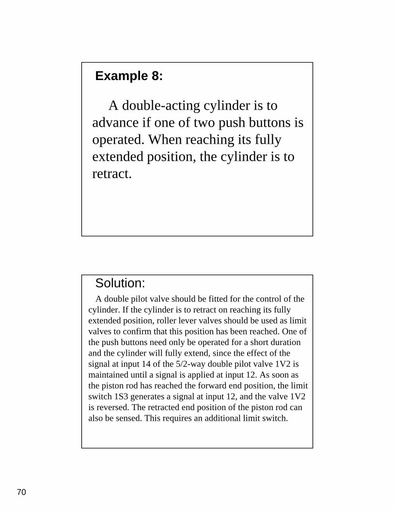
Example 8:
A double-acting cylinder is to d if f t h b tt iadvance if one of two push buttons is
operated. When reaching its fully extended position, the cylinder is to retract.
Solution:A double pilot valve should be fitted for the control of the
cylinder. If the cylinder is to retract on reaching its fully extended position, roller lever valves should be used as limit valves to confirm that this position has been reached One ofvalves to confirm that this position has been reached. One of the push buttons need only be operated for a short duration and the cylinder will fully extend, since the effect of the signal at input 14 of the 5/2-way double pilot valve 1V2 is maintained until a signal is applied at input 12. As soon as the piston rod has reached the forward end position, the limit switch 1S3 generates a signal at input 12, and the valve 1V2 is reversed. The retracted end position of the piston rod can also be sensed. This requires an additional limit switch.
71
Circuit Diagram
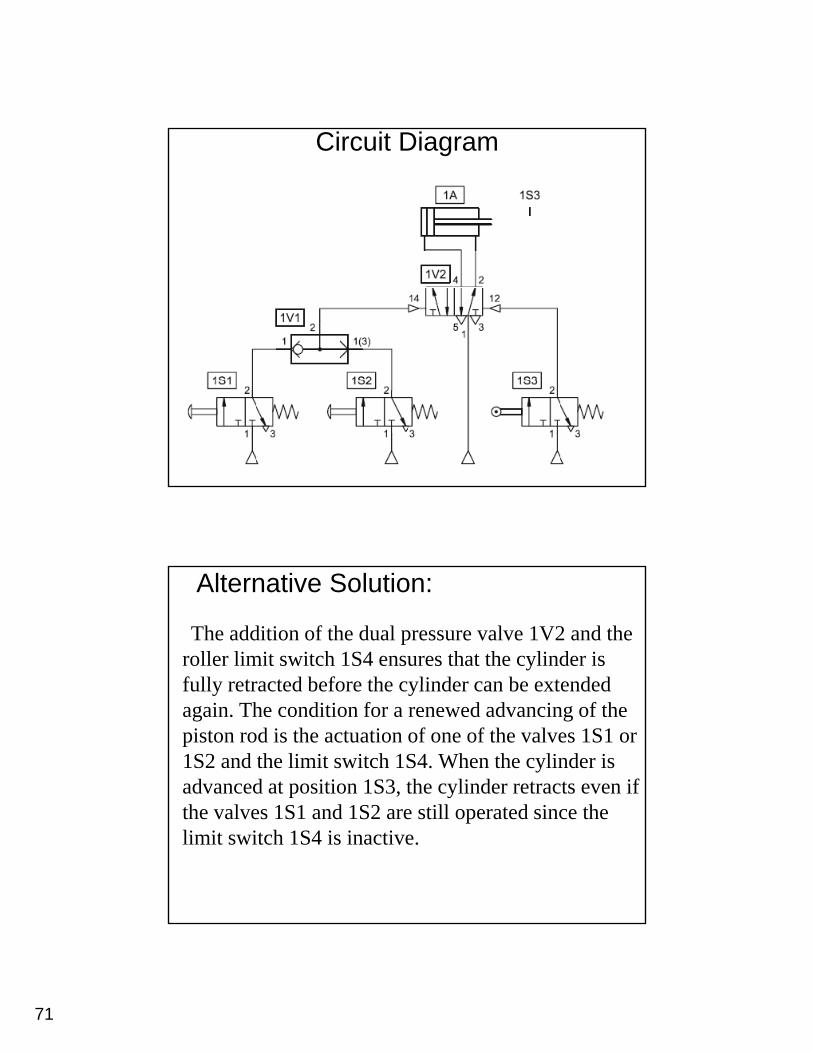
Alternative Solution:
The addition of the dual pressure valve 1V2 and the roller limit switch 1S4 ensures that the cylinder is fully retracted before the cylinder can be extendedfully retracted before the cylinder can be extended again. The condition for a renewed advancing of the piston rod is the actuation of one of the valves 1S1 or 1S2 and the limit switch 1S4. When the cylinder is advanced at position 1S3, the cylinder retracts even if h l 1S1 d 1S2 ill d i hthe valves 1S1 and 1S2 are still operated since the
limit switch 1S4 is inactive.
72
Circuit Diagram
Circuit Diagram
73
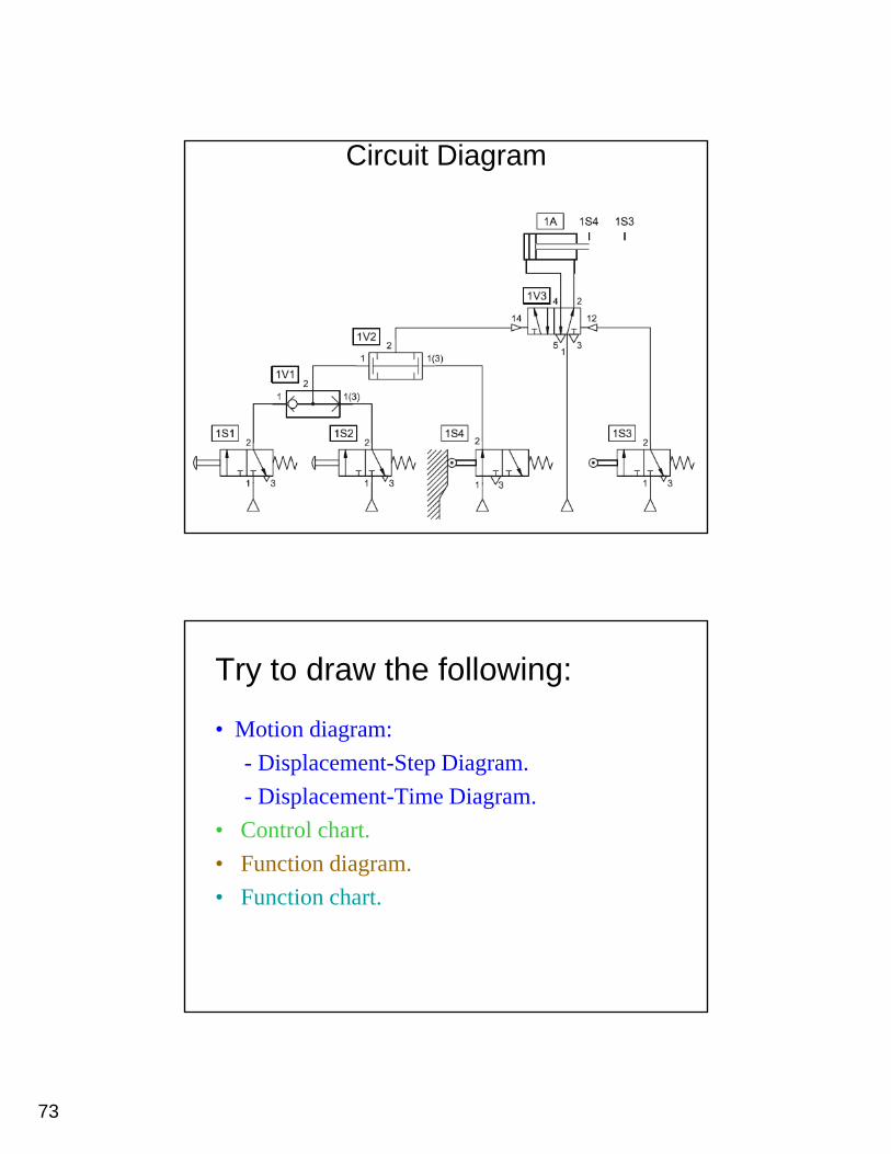
Circuit Diagram
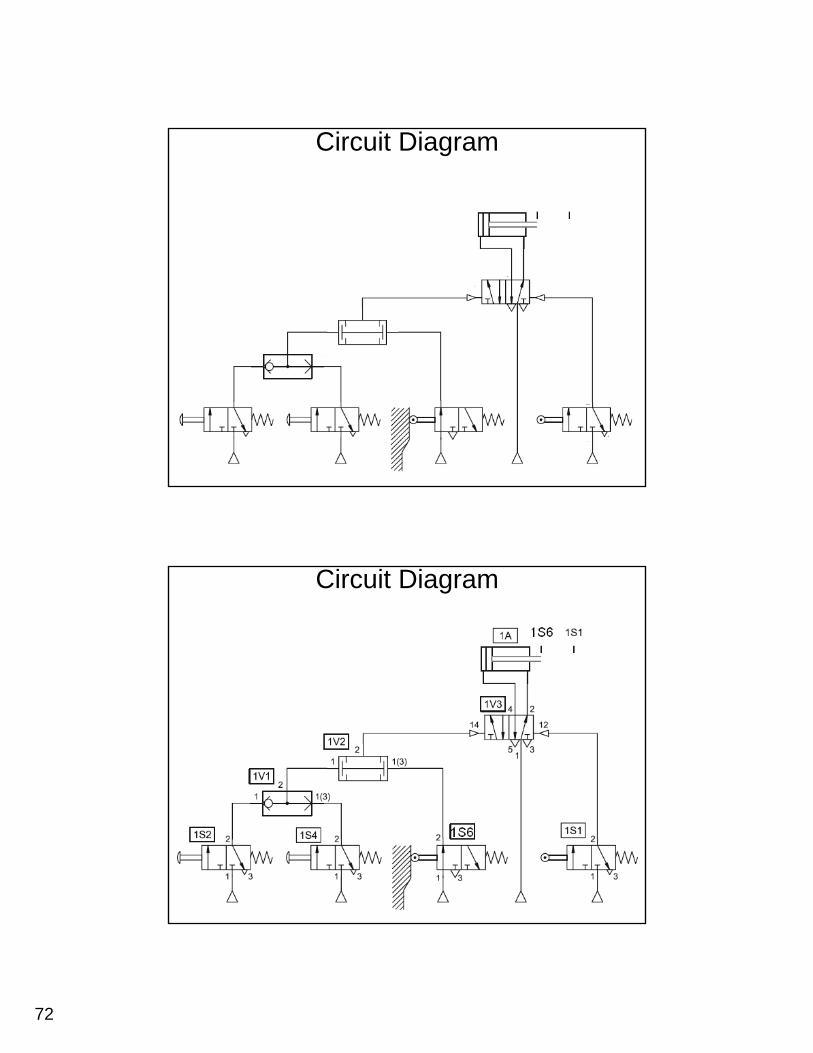
Try to draw the following:
• Motion diagram: - Displacement-Step Diagram.- Displacement-Time Diagram.
• Control chart.• Function diagram.• Function chart.
74
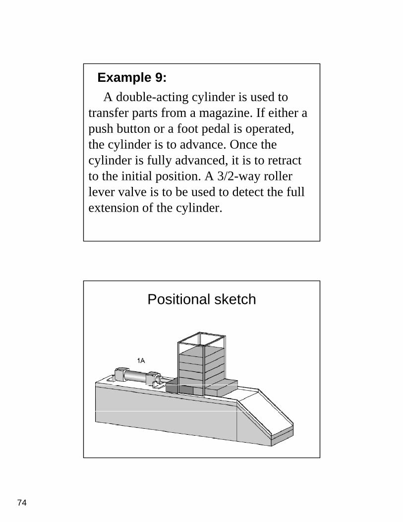
Example 9:A double-acting cylinder is used to
transfer parts from a magazine. If either a push button or a foot pedal is operated, the cylinder is to advance. Once the cylinder is fully advanced, it is to retract to the initial position. A 3/2-way roller p ylever valve is to be used to detect the full extension of the cylinder.
Positional sketch
75
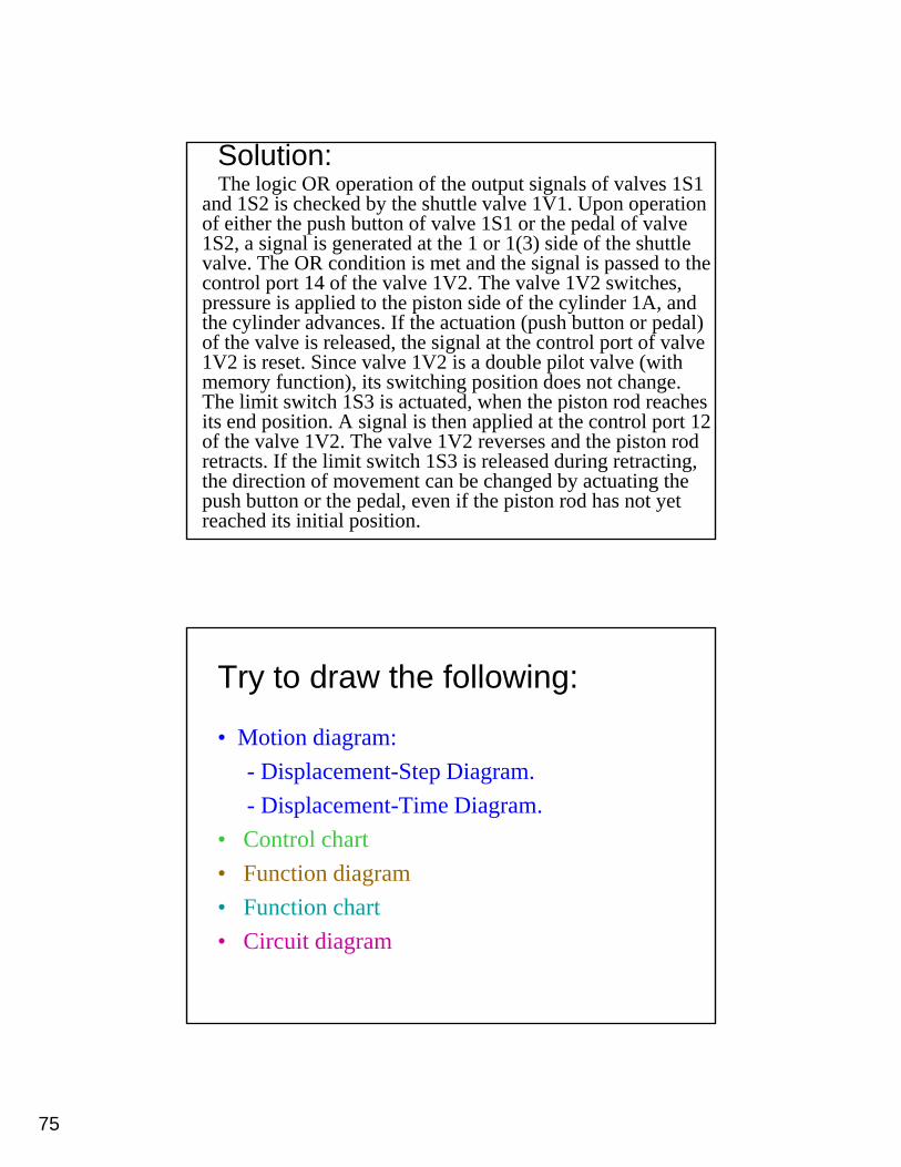
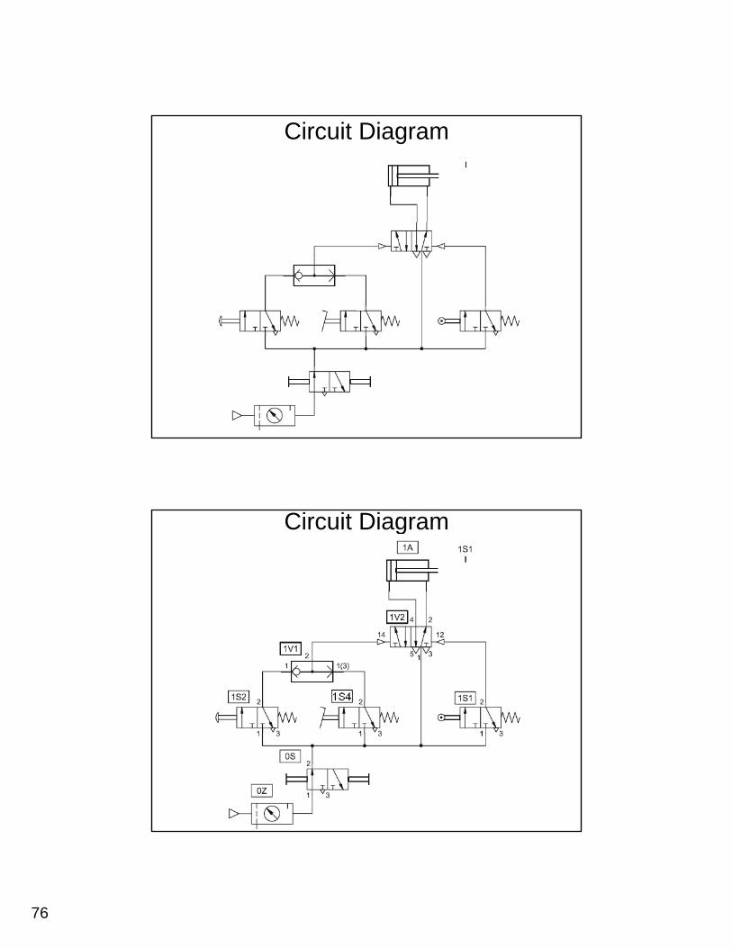
Solution:The logic OR operation of the output signals of valves 1S1
and 1S2 is checked by the shuttle valve 1V1. Upon operation of either the push button of valve 1S1 or the pedal of valve 1S2, a signal is generated at the 1 or 1(3) side of the shuttle valve. The OR condition is met and the signal is passed to the control port 14 of the valve 1V2. The valve 1V2 switches, pressure is applied to the piston side of the cylinder 1A, and the cylinder advances. If the actuation (push button or pedal) of the valve is released, the signal at the control port of valve 1V2 is reset. Since valve 1V2 is a double pilot valve (with memory function), its switching position does not change. The limit switch 1S3 is actuated, when the piston rod reachesThe limit switch 1S3 is actuated, when the piston rod reaches its end position. A signal is then applied at the control port 12 of the valve 1V2. The valve 1V2 reverses and the piston rod retracts. If the limit switch 1S3 is released during retracting, the direction of movement can be changed by actuating the push button or the pedal, even if the piston rod has not yet reached its initial position.
Try to draw the following:
• Motion diagram: - Displacement-Step Diagram.- Displacement-Time Diagram.
• Control chart• Function diagram• Function chart• Circuit diagram
76
Circuit Diagram
Circuit Diagram
77
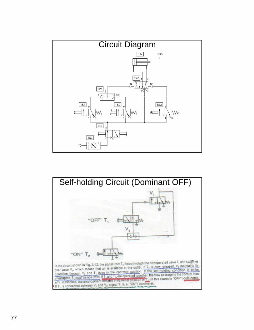
Circuit Diagram
Self-holding Circuit (Dominant OFF)
78
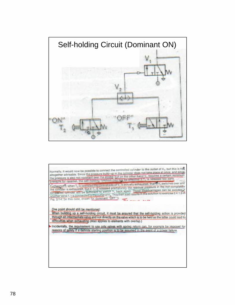
Self-holding Circuit (Dominant ON)
79
80
81
82
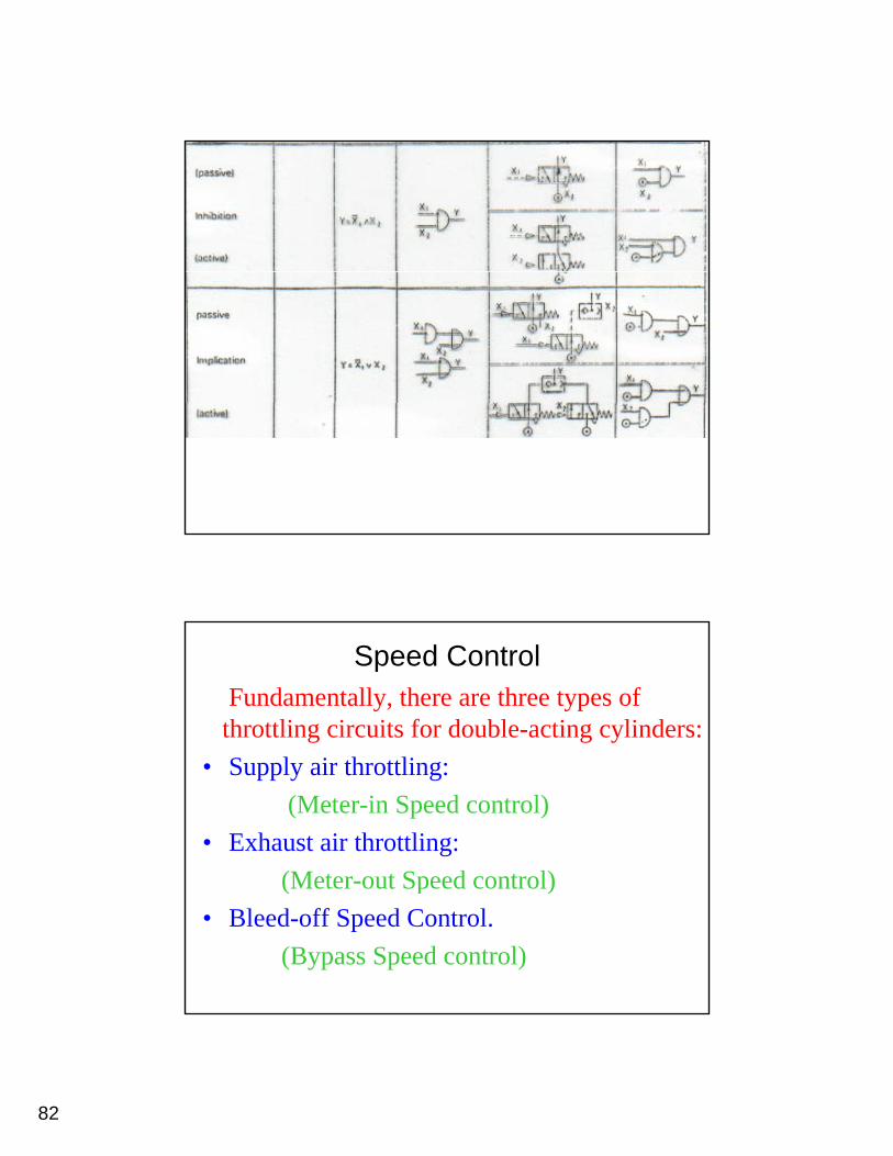
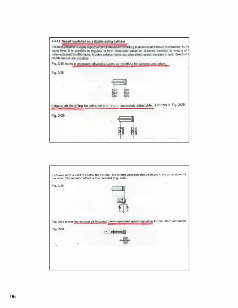
Speed ControlFundamentally, there are three types of throttling circuits for double-acting cylinders:
• Supply air throttling:(Meter-in Speed control)
• Exhaust air throttling:(Meter-out Speed control)(Meter-out Speed control)
• Bleed-off Speed Control.(Bypass Speed control)
83
Meter-in Speed Control (Supply air throttling)
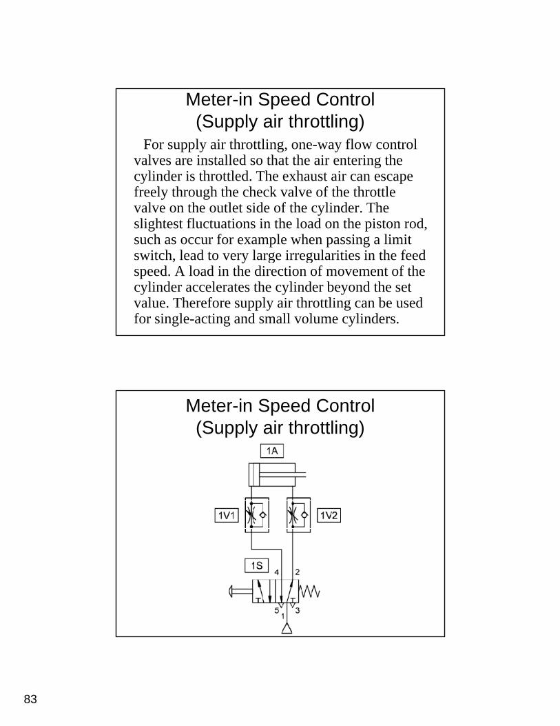
For supply air throttling, one-way flow control valves are installed so that the air entering the
li d i h l d h h icylinder is throttled. The exhaust air can escape freely through the check valve of the throttle valve on the outlet side of the cylinder. The slightest fluctuations in the load on the piston rod, such as occur for example when passing a limit s itch lead to er large irreg larities in the feedswitch, lead to very large irregularities in the feed speed. A load in the direction of movement of the cylinder accelerates the cylinder beyond the set value. Therefore supply air throttling can be used for single-acting and small volume cylinders.
Meter-in Speed Control (Supply air throttling)
84
Meter-in Speed Control (Supply air throttling)
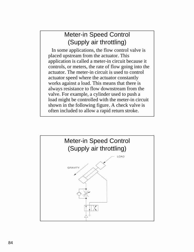
In some applications, the flow control valve is placed upstream from the actuator. This
li i i ll d i i i b iapplication is called a meter-in circuit because it controls, or meters, the rate of flow going into the actuator. The meter-in circuit is used to control actuator speed where the actuator constantly works against a load. This means that there is al a s resistance to flo do nstream from thealways resistance to flow downstream from the valve. For example, a cylinder used to push a load might be controlled with the meter-in circuit shown in the following figure. A check valve is often included to allow a rapid return stroke.
Meter-in Speed Control (Supply air throttling)
85
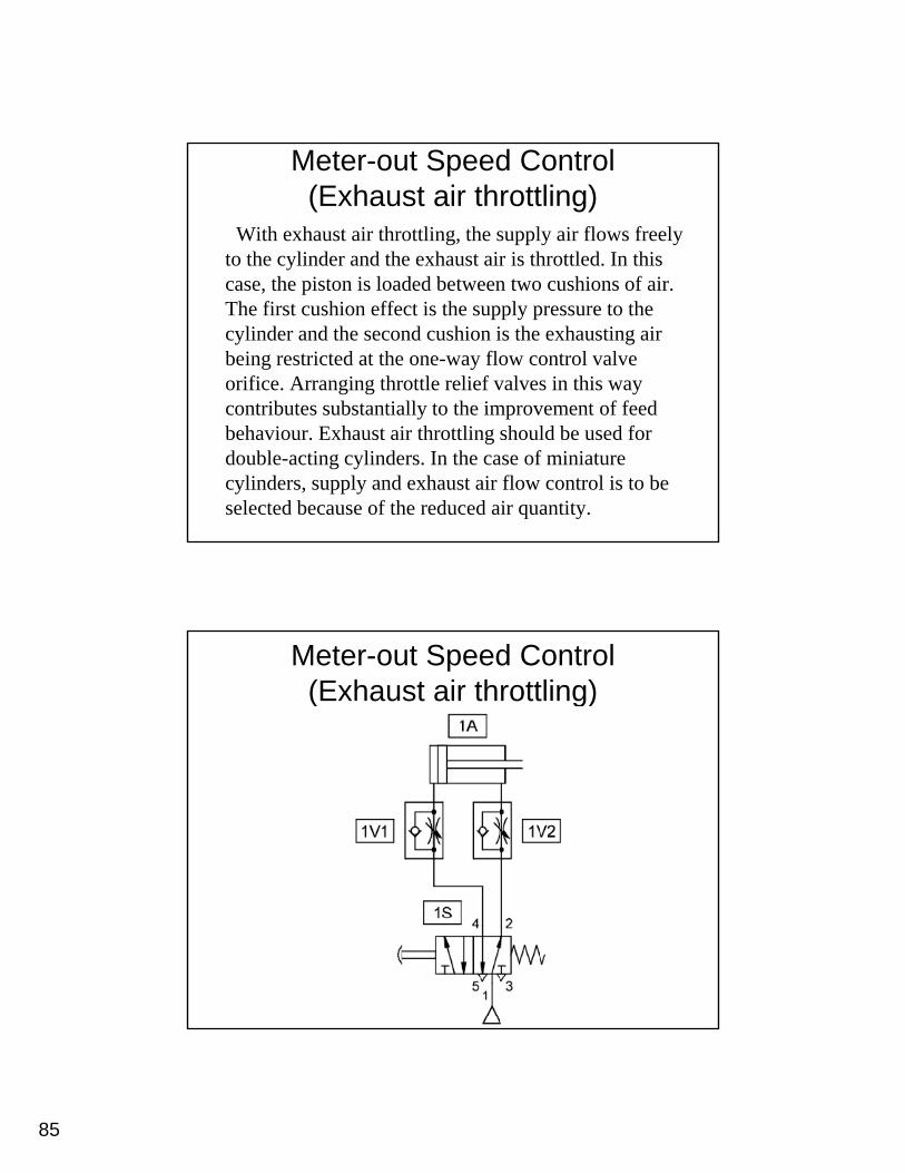
Meter-out Speed Control (Exhaust air throttling)
With exhaust air throttling, the supply air flows freely to the cylinder and the exhaust air is throttled. In this case, the piston is loaded between two cushions of air. The first cushion effect is the supply pressure to the cylinder and the second cushion is the exhausting air being restricted at the one-way flow control valve orifice. Arranging throttle relief valves in this way contributes substantially to the improvement of feedcontributes substantially to the improvement of feed behaviour. Exhaust air throttling should be used for double-acting cylinders. In the case of miniature cylinders, supply and exhaust air flow control is to be selected because of the reduced air quantity.
Meter-out Speed Control (Exhaust air throttling)
86
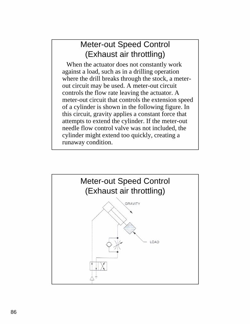
Meter-out Speed Control (Exhaust air throttling)
When the actuator does not constantly work against a load, such as in a drilling operation
h h d ill b k h h h kwhere the drill breaks through the stock, a meter-out circuit may be used. A meter-out circuit controls the flow rate leaving the actuator. A meter-out circuit that controls the extension speed of a cylinder is shown in the following figure. In this circ it gra it applies a constant force thatthis circuit, gravity applies a constant force that attempts to extend the cylinder. If the meter-out needle flow control valve was not included, the cylinder might extend too quickly, creating a runaway condition.
Meter-out Speed Control (Exhaust air throttling)
87
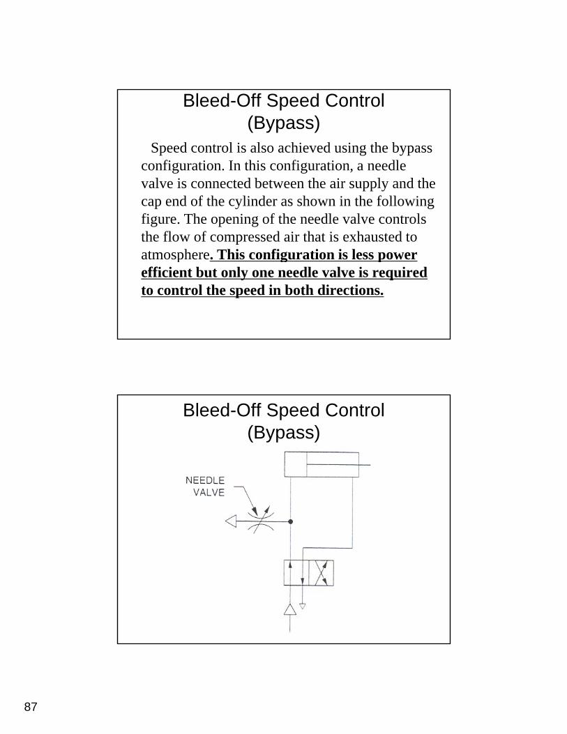
Bleed-Off Speed Control(Bypass)
Speed control is also achieved using the bypass configuration. In this configuration, a needle g g ,valve is connected between the air supply and the cap end of the cylinder as shown in the following figure. The opening of the needle valve controls the flow of compressed air that is exhausted to atmosphere This configuration is less poweratmosphere. This configuration is less power efficient but only one needle valve is required to control the speed in both directions.
Bleed-Off Speed Control(Bypass)
88
89
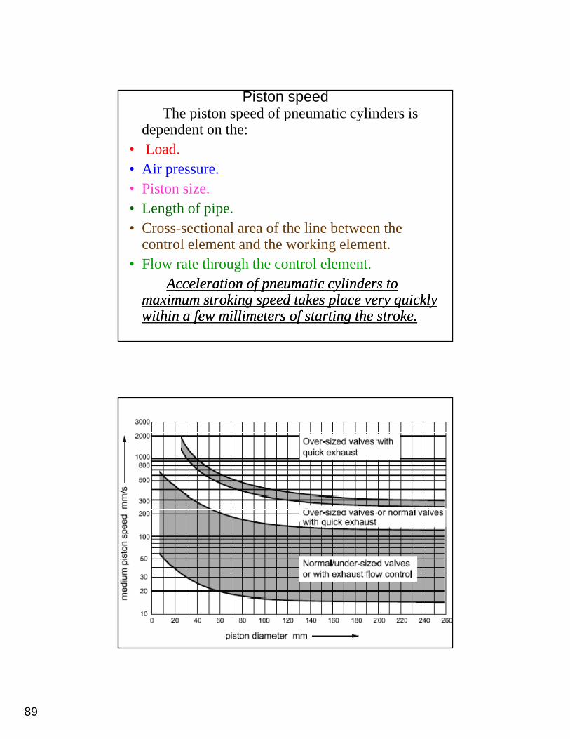
Piston speedThe piston speed of pneumatic cylinders is
dependent on the:• Load.• Air pressure.p essu e.• Piston size.• Length of pipe.• Cross-sectional area of the line between the
control element and the working element.• Flow rate through the control element.
Acceleration of pneumatic cylinders to Acceleration of pneumatic cylinders to maximum stroking speed takes place very quickly maximum stroking speed takes place very quickly within a few millimeters of starting the stroke. within a few millimeters of starting the stroke.
90
Circuits for Cylinder Speed Regulation
• Reducing the speed: this is achieved by using:Th ttl l- Throttle valves.
- Hydraulic Check unit.- Cushioning.- Hydraulic Damper (Dashpot).y p ( p )
• Increasing the speed: this is achieved by using quick exhaust valve.
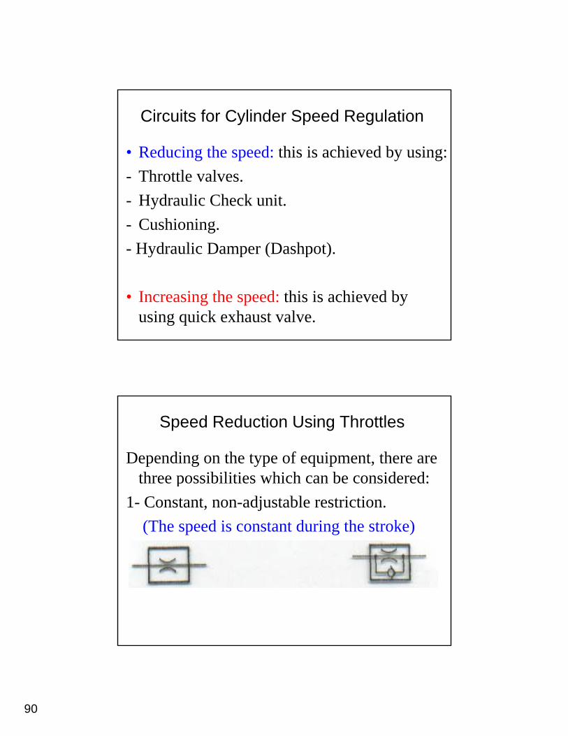
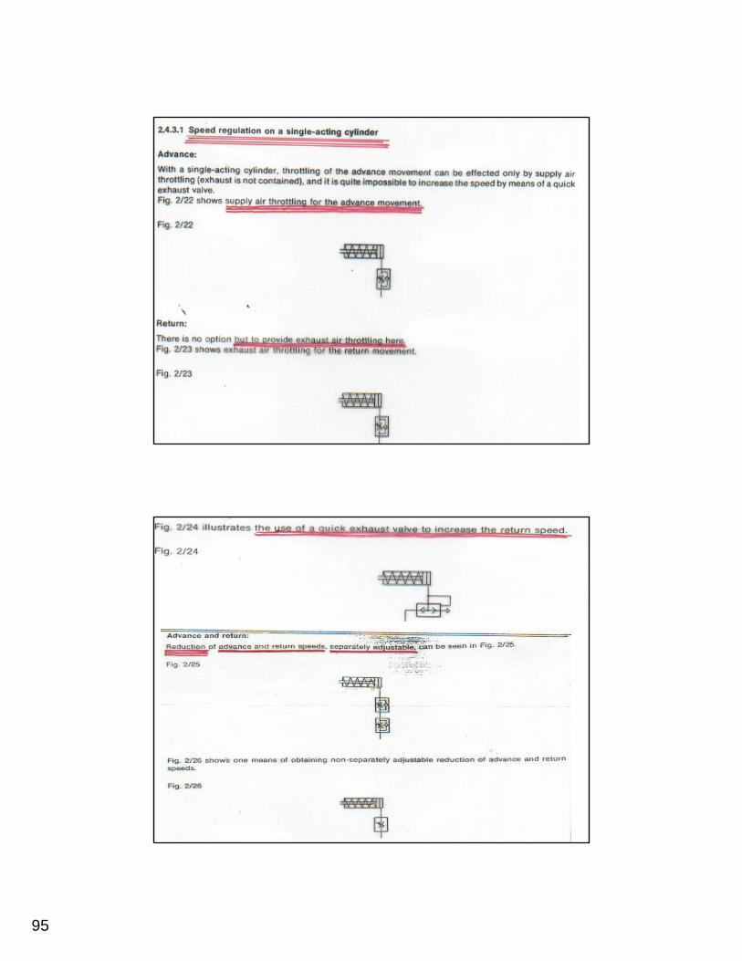
Speed Reduction Using Throttles
Depending on the type of equipment, there are three possibilities which can be considered:three possibilities which can be considered:
1- Constant, non-adjustable restriction.(The speed is constant during the stroke)
91
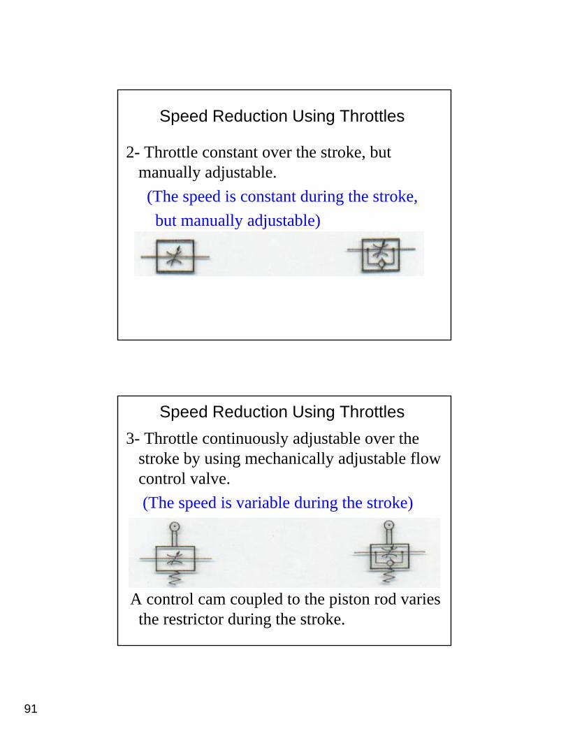
Speed Reduction Using Throttles
2- Throttle constant over the stroke, but manually adjustablemanually adjustable. (The speed is constant during the stroke, but manually adjustable)
Speed Reduction Using Throttles 3- Throttle continuously adjustable over the
stroke by using mechanically adjustable flow control valvecontrol valve. (The speed is variable during the stroke)
A control cam coupled to the piston rod varies the restrictor during the stroke.
92
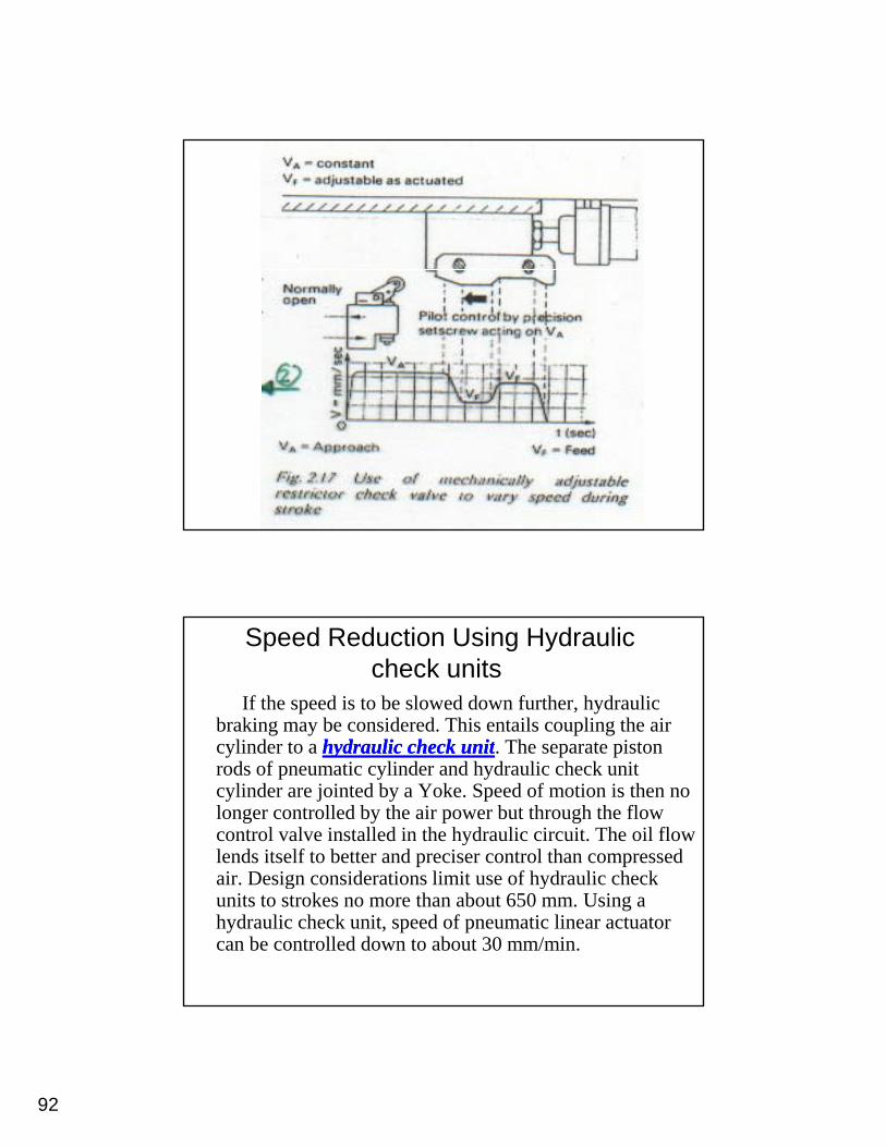
Speed Reduction Using Hydraulic check units
If the speed is to be slowed down further, hydraulic braking may be considered. This entails coupling the air cylinder to a hydraulic check unithydraulic check unit The separate pistoncylinder to a hydraulic check unithydraulic check unit. The separate piston rods of pneumatic cylinder and hydraulic check unit cylinder are jointed by a Yoke. Speed of motion is then no longer controlled by the air power but through the flow control valve installed in the hydraulic circuit. The oil flow lends itself to better and preciser control than compressed air Design considerations limit use of hydraulic checkair. Design considerations limit use of hydraulic check units to strokes no more than about 650 mm. Using a hydraulic check unit, speed of pneumatic linear actuator can be controlled down to about 30 mm/min.

93
Speed Reduction Using cushioning and hydraulic dashpot
94
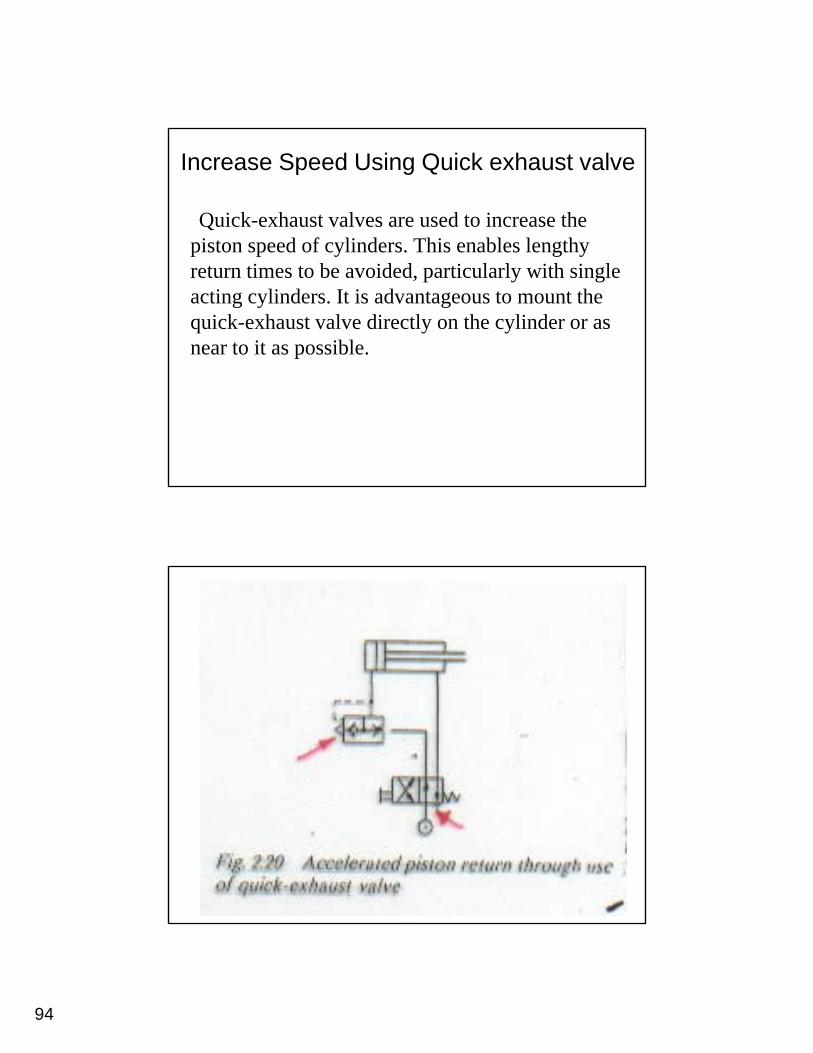
Increase Speed Using Quick exhaust valve
Quick-exhaust valves are used to increase the piston speed of cylinders This enables lengthypiston speed of cylinders. This enables lengthy return times to be avoided, particularly with single acting cylinders. It is advantageous to mount the quick-exhaust valve directly on the cylinder or as near to it as possible.
95
96
97
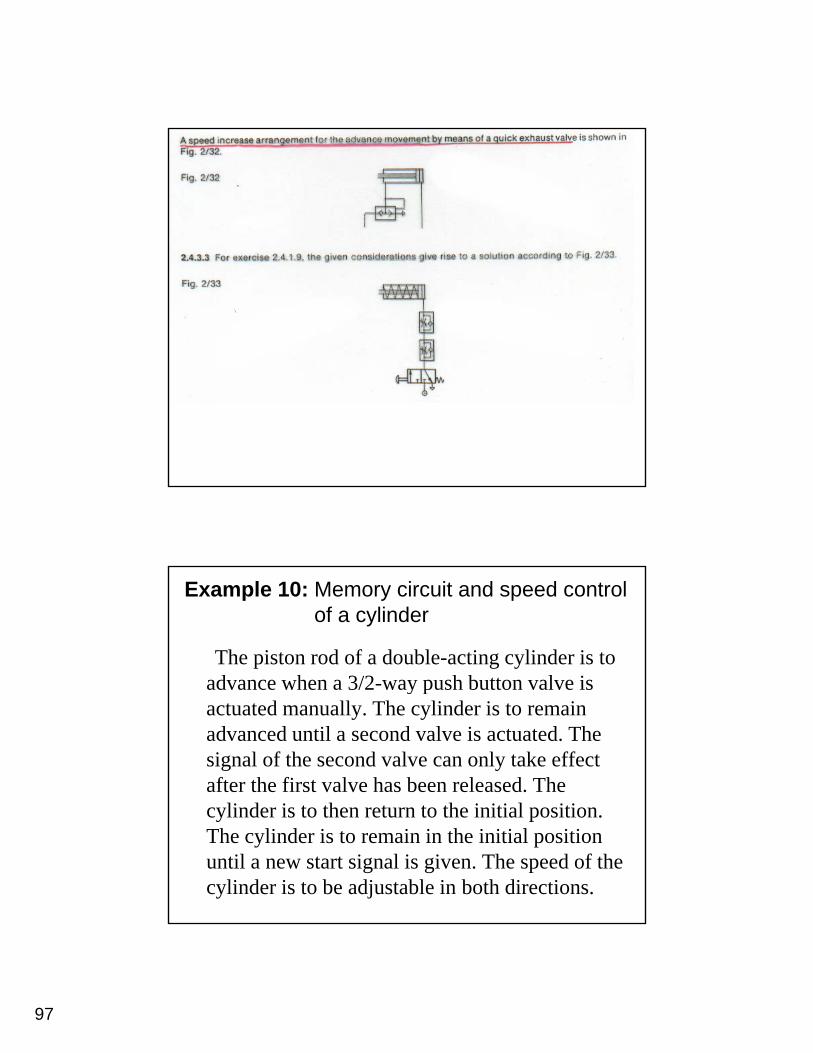
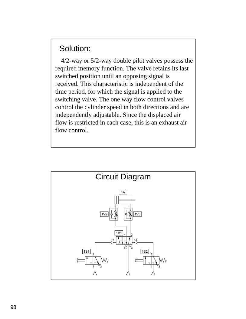
Example 10: Memory circuit and speed control of a cylinder
The piston rod of a double-acting cylinder is to advance when a 3/2-way push button valve isadvance when a 3/2-way push button valve is actuated manually. The cylinder is to remain advanced until a second valve is actuated. The signal of the second valve can only take effect after the first valve has been released. The
li d i t th t t th i iti l iticylinder is to then return to the initial position. The cylinder is to remain in the initial position until a new start signal is given. The speed of the cylinder is to be adjustable in both directions.
98
Solution:4/2-way or 5/2-way double pilot valves possess the
required memory function. The valve retains its last it h d iti til i i l iswitched position until an opposing signal is
received. This characteristic is independent of the time period, for which the signal is applied to the switching valve. The one way flow control valves control the cylinder speed in both directions and are independently adjustable. Since the displaced air flow is restricted in each case, this is an exhaust air flow control.
Circuit Diagram
99
Circuit Diagram
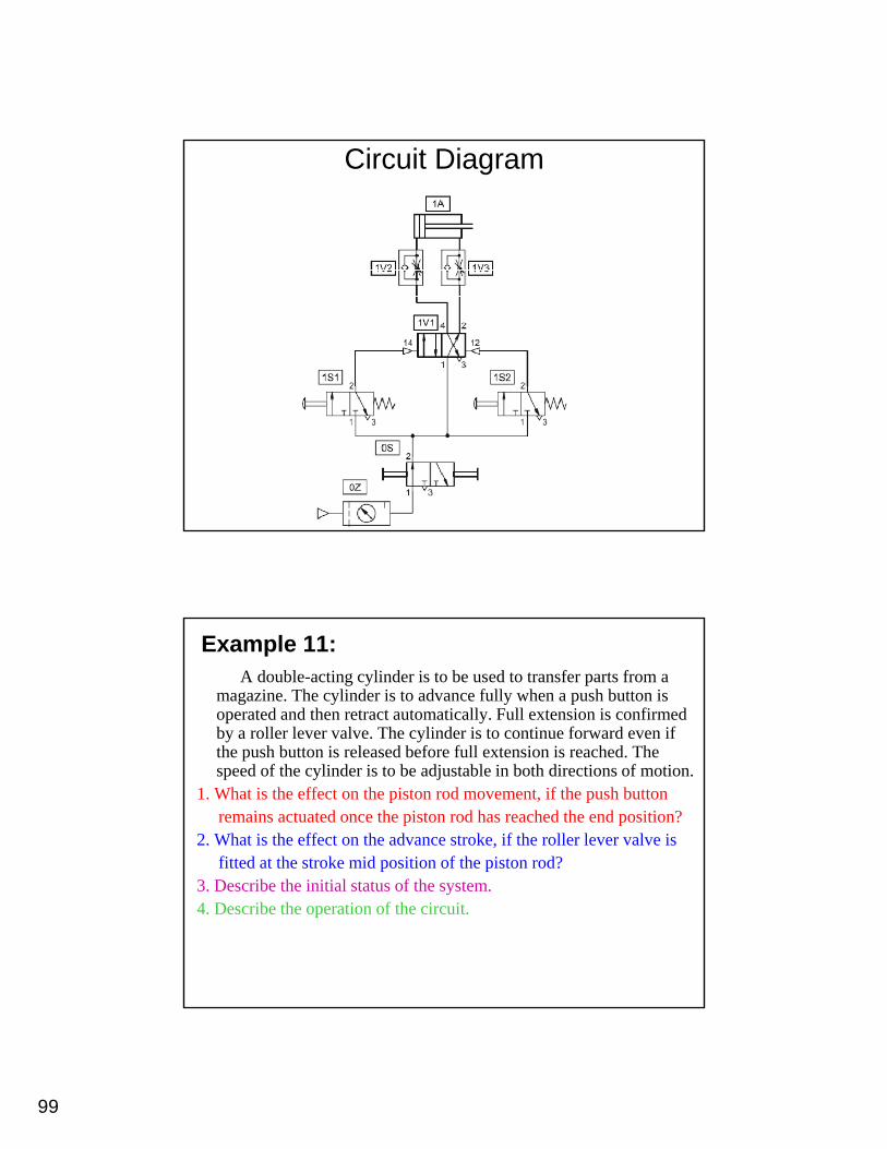
Example 11:A double-acting cylinder is to be used to transfer parts from a
magazine. The cylinder is to advance fully when a push button is operated and then retract automatically. Full extension is confirmed by a roller lever valve. The cylinder is to continue forward even if th h b tt i l d b f f ll t i i h d Ththe push button is released before full extension is reached. The speed of the cylinder is to be adjustable in both directions of motion.
1. What is the effect on the piston rod movement, if the push buttonremains actuated once the piston rod has reached the end position?
2. What is the effect on the advance stroke, if the roller lever valve isfitted at the stroke mid position of the piston rod?
3. Describe the initial status of the system.4. Describe the operation of the circuit.
100
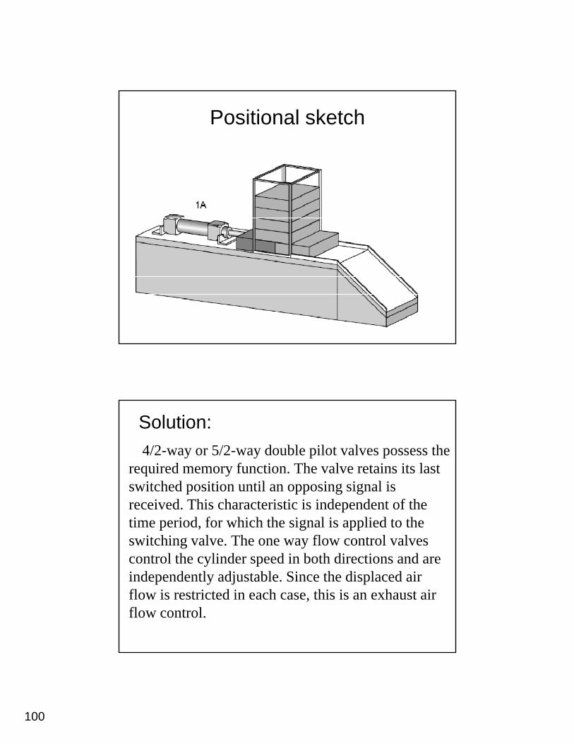
Positional sketch
Solution:4/2-way or 5/2-way double pilot valves possess the
required memory function. The valve retains its last it h d iti til i i l iswitched position until an opposing signal is
received. This characteristic is independent of the time period, for which the signal is applied to the switching valve. The one way flow control valves control the cylinder speed in both directions and are independently adjustable. Since the displaced air flow is restricted in each case, this is an exhaust air flow control.
101
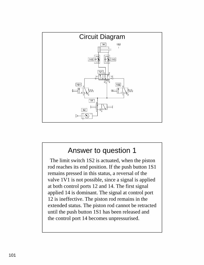
Circuit Diagram
Answer to question 1The limit switch 1S2 is actuated, when the piston
rod reaches its end position. If the push button 1S1 i d i thi t t l f thremains pressed in this status, a reversal of the
valve 1V1 is not possible, since a signal is applied at both control ports 12 and 14. The first signal applied 14 is dominant. The signal at control port 12 is ineffective. The piston rod remains in the extended status. The piston rod cannot be retracted until the push button 1S1 has been released and the control port 14 becomes unpressurised.
102
Answer to question 2If the roller lever valve 1S2 is fitted at the stroke
mid-position, then the piston rod retracts again upon reaching this position However this is notupon reaching this position. However, this is not possible unless the push button 1S1 has already been released again. If the push button 1S1 has not yet been released at this point, the piston rod overtravels the limit switch 1S2 and travels up to the cylinder stop. A return stroke is not possible y p punless the roller lever valve has been manually actuated or with the help of the manual override of the control element 1V1.
Answer to question 3Both valves 1S1 and 1S2 are unactuated in the
initial position. The switching position of the valve 1V1 i h th t ti 1 d 2 d1V1 is such that connections 1 and 2 and connection 4 and 5 are each interconnected. With this, pressure is applied at the piston rod side of the cylinder 1A and the piston rod remains in the retracted status.
103
Answer to question 4If push button 1S1 is actuated, a signal is applied at the
input 14 of the valve 1V1. The valve 1V1 switches, pressure is applied at the piston side of the cylinder 1A and the piston rod advances. Upon reaching the end position, the piston rod actuates the limit switch 1S2, and a signal is applied at the control port 12 of the valve 1V1. This reverses and the piston rod retracts. The speed of the piston rod is set via the adjusting screw on the flow control valves 1V2 and 1V3 (exhaust air flow control). After each of the valves 1S1 and 1S2 has been released, the control ports become pressureless. The use of a double pilot valve (valve 1V1 has a memory function) ensures that the switching position does not change.
Example 12: The quick exhaust valve
The combined actuation of a manually actuated valve and a roller lever valve advances a forming tool on an edge-folding device. The forming tool is driven by a double-acting cylinder. For rapid forward travel, the circuit utilises a quick exhaust valve. The retracting speed is to be adjustable. If either of the two valves are released,adjustable. If either of the two valves are released, the tool returns to its initial position.
104
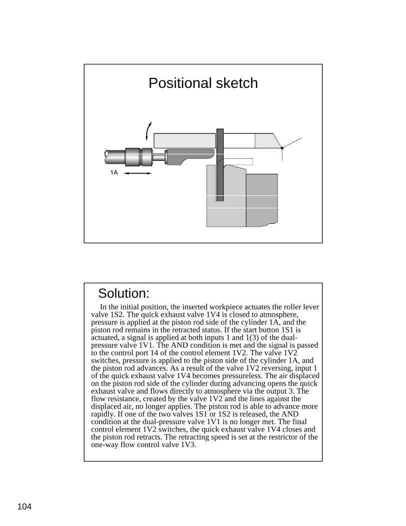
Positional sketch
Solution:In the initial position, the inserted workpiece actuates the roller lever
valve 1S2. The quick exhaust valve 1V4 is closed to atmosphere, pressure is applied at the piston rod side of the cylinder 1A, and the piston rod remains in the retracted status. If the start button 1S1 is actuated, a signal is applied at both inputs 1 and 1(3) of the dual-
l 1 1 h A di i i d h i l i dpressure valve 1V1. The AND condition is met and the signal is passed to the control port 14 of the control element 1V2. The valve 1V2 switches, pressure is applied to the piston side of the cylinder 1A, and the piston rod advances. As a result of the valve 1V2 reversing, input 1 of the quick exhaust valve 1V4 becomes pressureless. The air displaced on the piston rod side of the cylinder during advancing opens the quick exhaust valve and flows directly to atmosphere via the output 3. The flow resistance, created by the valve 1V2 and the lines against the , y gdisplaced air, no longer applies. The piston rod is able to advance more rapidly. If one of the two valves 1S1 or 1S2 is released, the AND condition at the dual-pressure valve 1V1 is no longer met. The final control element 1V2 switches, the quick exhaust valve 1V4 closes and the piston rod retracts. The retracting speed is set at the restrictor of the one-way flow control valve 1V3.
105
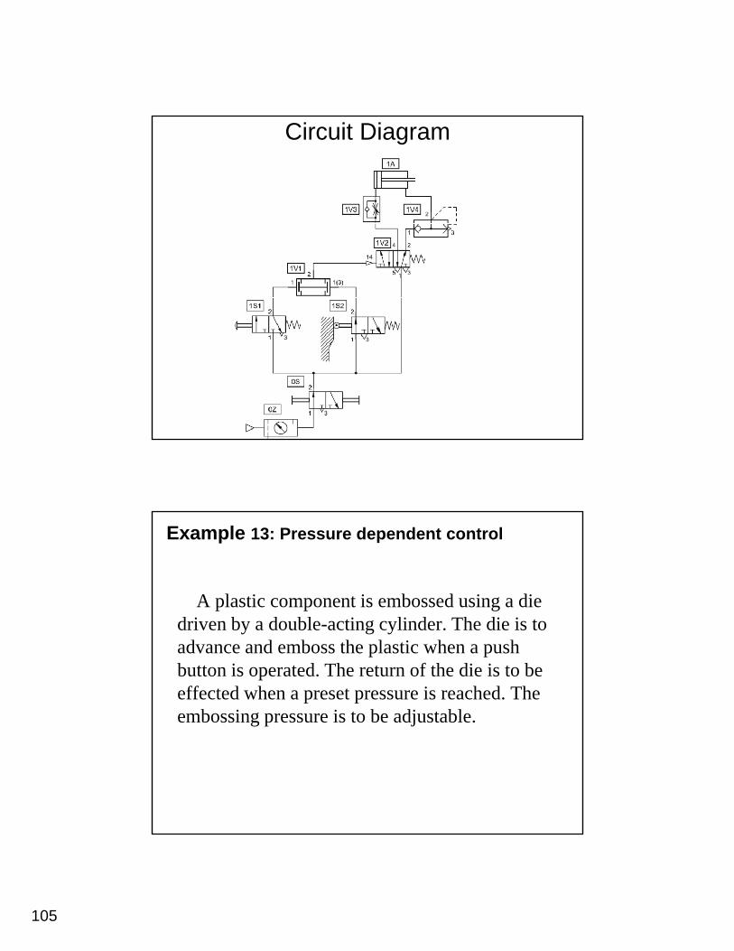
Circuit Diagram
Example 13: Pressure dependent control
A plastic component is embossed using a die d i b d bl ti li d Th di i tdriven by a double-acting cylinder. The die is to advance and emboss the plastic when a push button is operated. The return of the die is to be effected when a preset pressure is reached. The embossing pressure is to be adjustable.
106
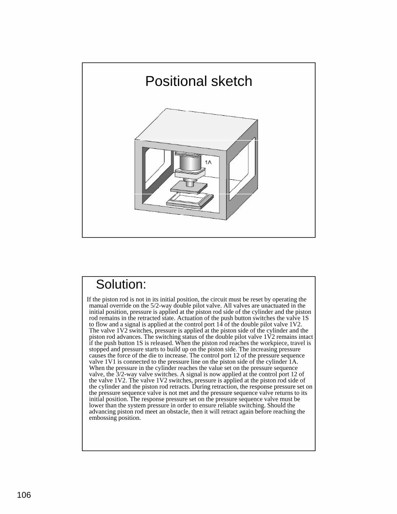
Positional sketch
Solution:If the piston rod is not in its initial position, the circuit must be reset by operating the manual override on the 5/2-way double pilot valve. All valves are unactuated in the initial position, pressure is applied at the piston rod side of the cylinder and the piston rod remains in the retracted state. Actuation of the push button switches the valve 1S to flow and a signal is applied at the control port 14 of the double pilot valve 1V2. The valve 1V2 switches, pressure is applied at the piston side of the cylinder and the
i d d h i hi f h d bl il l 1 2 i ipiston rod advances. The switching status of the double pilot valve 1V2 remains intact if the push button 1S is released. When the piston rod reaches the workpiece, travel is stopped and pressure starts to build up on the piston side. The increasing pressure causes the force of the die to increase. The control port 12 of the pressure sequence valve 1V1 is connected to the pressure line on the piston side of the cylinder 1A. When the pressure in the cylinder reaches the value set on the pressure sequence valve, the 3/2-way valve switches. A signal is now applied at the control port 12 of the valve 1V2. The valve 1V2 switches, pressure is applied at the piston rod side of the cylinder and the piston rod retracts. During retraction, the response pressure set on the pressure sequence valve is not met and the pressure sequence valve returns to itsthe pressure sequence valve is not met and the pressure sequence valve returns to its initial position. The response pressure set on the pressure sequence valve must be lower than the system pressure in order to ensure reliable switching. Should the advancing piston rod meet an obstacle, then it will retract again before reaching the embossing position.
107
Circuit Diagram
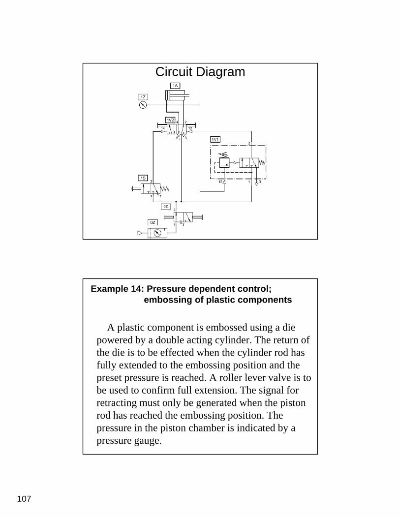
Example 14: Pressure dependent control;embossing of plastic components
A plastic component is embossed using a die d b d bl ti li d Th t fpowered by a double acting cylinder. The return of
the die is to be effected when the cylinder rod has fully extended to the embossing position and the preset pressure is reached. A roller lever valve is to be used to confirm full extension. The signal for retracting must only be generated when the piston rod has reached the embossing position. The pressure in the piston chamber is indicated by a pressure gauge.
108
Positional sketch
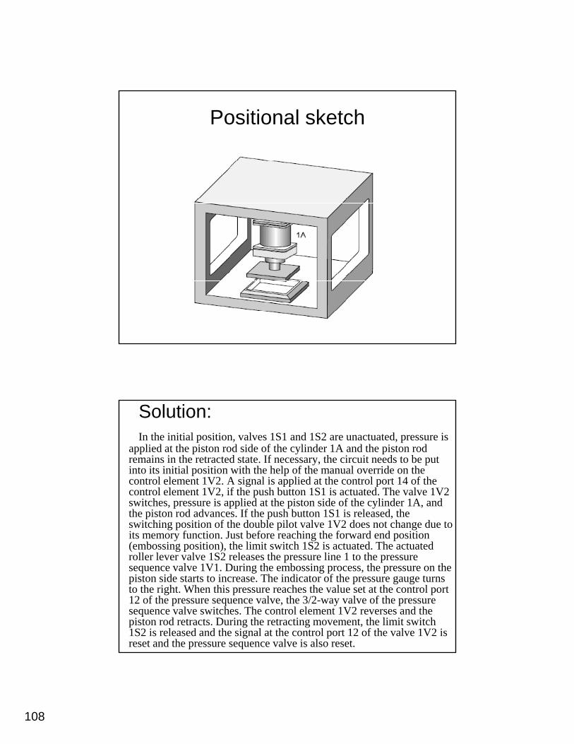
Solution:In the initial position, valves 1S1 and 1S2 are unactuated, pressure is
applied at the piston rod side of the cylinder 1A and the piston rod remains in the retracted state. If necessary, the circuit needs to be put into its initial position with the help of the manual override on the control element 1V2. A signal is applied at the control port 14 of thecontrol element 1V2. A signal is applied at the control port 14 of the control element 1V2, if the push button 1S1 is actuated. The valve 1V2 switches, pressure is applied at the piston side of the cylinder 1A, and the piston rod advances. If the push button 1S1 is released, the switching position of the double pilot valve 1V2 does not change due to its memory function. Just before reaching the forward end position (embossing position), the limit switch 1S2 is actuated. The actuated roller lever valve 1S2 releases the pressure line 1 to the pressure sequence valve 1V1 During the embossing process the pressure on thesequence valve 1V1. During the embossing process, the pressure on the piston side starts to increase. The indicator of the pressure gauge turns to the right. When this pressure reaches the value set at the control port 12 of the pressure sequence valve, the 3/2-way valve of the pressure sequence valve switches. The control element 1V2 reverses and the piston rod retracts. During the retracting movement, the limit switch 1S2 is released and the signal at the control port 12 of the valve 1V2 is reset and the pressure sequence valve is also reset.
109
Circuit Diagram
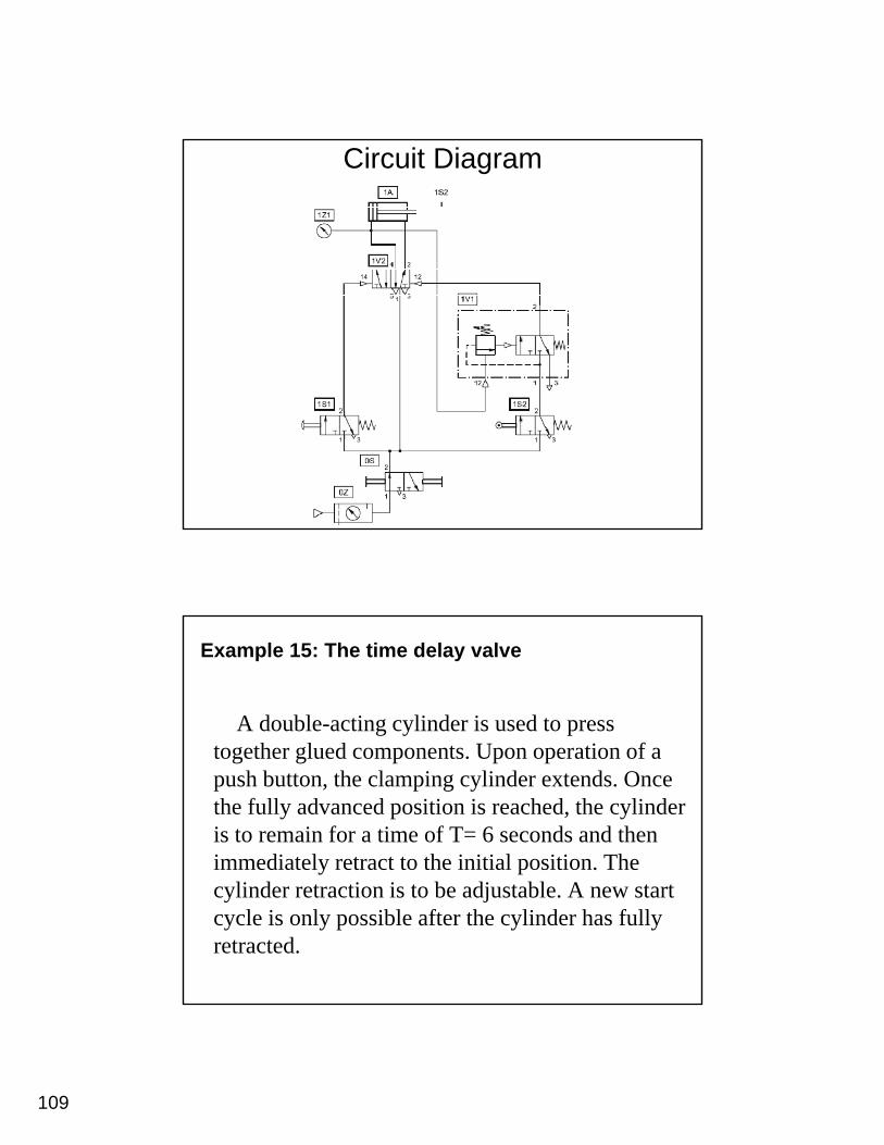
Example 15: The time delay valve
A double-acting cylinder is used to press t th l d t U ti ftogether glued components. Upon operation of a push button, the clamping cylinder extends. Once the fully advanced position is reached, the cylinder is to remain for a time of T= 6 seconds and then immediately retract to the initial position. The cylinder retraction is to be adjustable. A new start cycle is only possible after the cylinder has fully retracted.
110
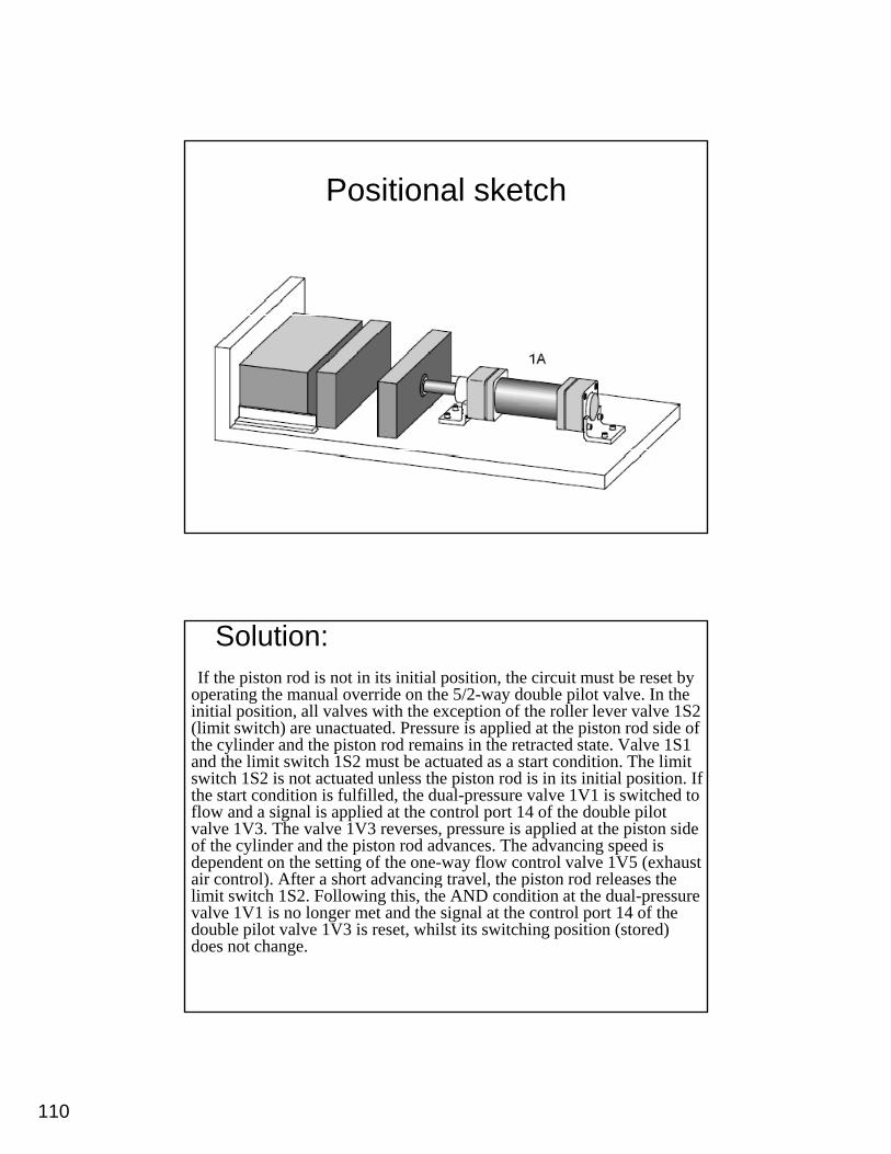
Positional sketch
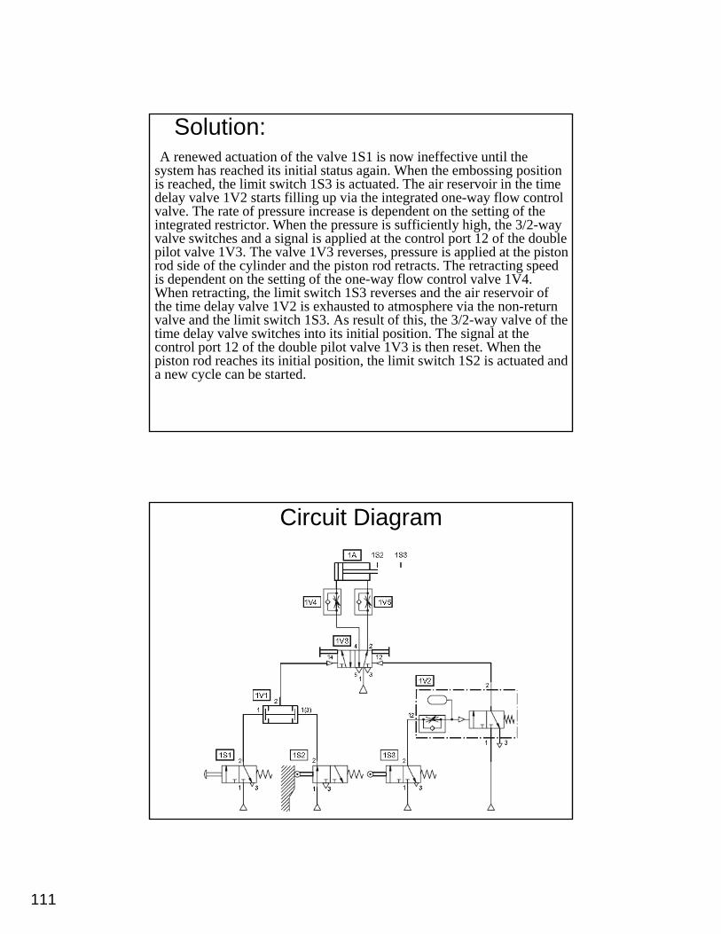
Solution:If the piston rod is not in its initial position, the circuit must be reset by
operating the manual override on the 5/2-way double pilot valve. In the initial position, all valves with the exception of the roller lever valve 1S2 (limit switch) are unactuated. Pressure is applied at the piston rod side of the cylinder and the piston rod remains in the retracted state. Valve 1S1 y pand the limit switch 1S2 must be actuated as a start condition. The limit switch 1S2 is not actuated unless the piston rod is in its initial position. If the start condition is fulfilled, the dual-pressure valve 1V1 is switched to flow and a signal is applied at the control port 14 of the double pilot valve 1V3. The valve 1V3 reverses, pressure is applied at the piston side of the cylinder and the piston rod advances. The advancing speed is dependent on the setting of the one-way flow control valve 1V5 (exhaust air control) After a short advancing travel the piston rod releases theair control). After a short advancing travel, the piston rod releases the limit switch 1S2. Following this, the AND condition at the dual-pressure valve 1V1 is no longer met and the signal at the control port 14 of the double pilot valve 1V3 is reset, whilst its switching position (stored) does not change.
111
Solution:A renewed actuation of the valve 1S1 is now ineffective until the
system has reached its initial status again. When the embossing position is reached, the limit switch 1S3 is actuated. The air reservoir in the time delay valve 1V2 starts filling up via the integrated one-way flow control valve. The rate of pressure increase is dependent on the setting of the i d i h h i ffi i l hi h h 3/2integrated restrictor. When the pressure is sufficiently high, the 3/2-way valve switches and a signal is applied at the control port 12 of the double pilot valve 1V3. The valve 1V3 reverses, pressure is applied at the piston rod side of the cylinder and the piston rod retracts. The retracting speed is dependent on the setting of the one-way flow control valve 1V4. When retracting, the limit switch 1S3 reverses and the air reservoir of the time delay valve 1V2 is exhausted to atmosphere via the non-return valve and the limit switch 1S3. As result of this, the 3/2-way valve of the , ytime delay valve switches into its initial position. The signal at the control port 12 of the double pilot valve 1V3 is then reset. When the piston rod reaches its initial position, the limit switch 1S2 is actuated and a new cycle can be started.
Circuit Diagram
112
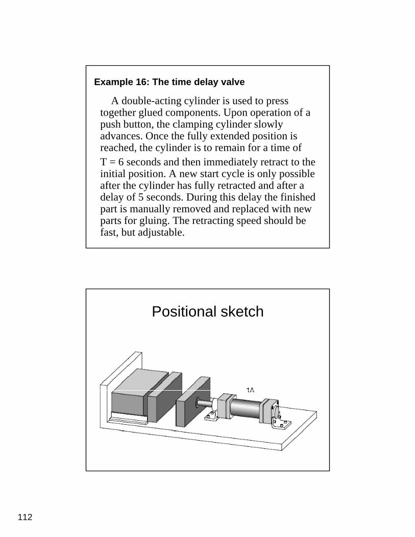
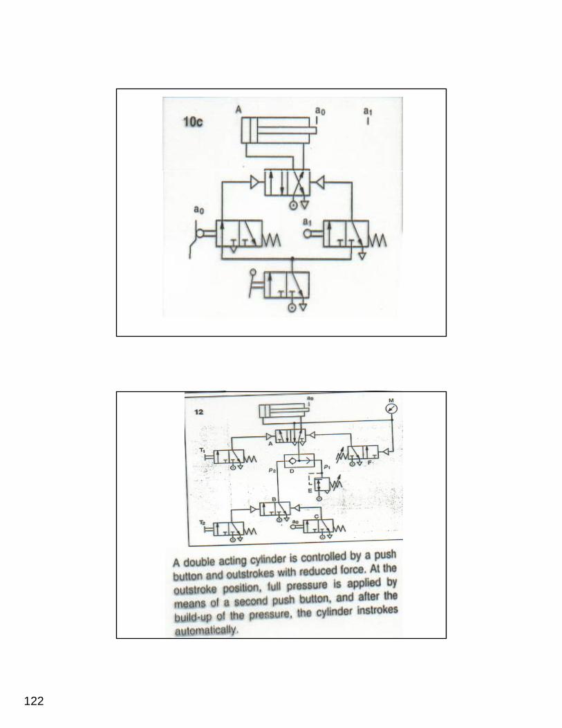
Example 16: The time delay valve
A double-acting cylinder is used to press together glued components. Upon operation of a push button the clamping cylinder slowlypush button, the clamping cylinder slowly advances. Once the fully extended position is reached, the cylinder is to remain for a time of T = 6 seconds and then immediately retract to the initial position. A new start cycle is only possible after the cylinder has fully retracted and after aafter the cylinder has fully retracted and after a delay of 5 seconds. During this delay the finished part is manually removed and replaced with new parts for gluing. The retracting speed should be fast, but adjustable.
Positional sketch
113
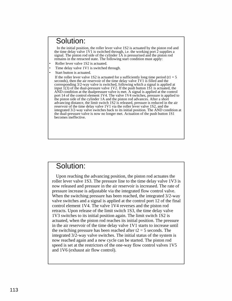
Solution:In the initial position, the roller lever valve 1S2 is actuated by the piston rod and
the time delay valve 1V1 is switched through, i.e. the working port 2 supplies a signal. The piston rod side of the cylinder 1A is pressurised and the piston rod remains in the retracted state. The following start condition must apply:
• Roller lever valve 1S2 is actuated.• Time delay valve 1V1 is switched through.• Start button is actuated.
If the roller lever valve 1S2 is actuated for a sufficiently long time period (t1 = 5 seconds), then the air reservoir of the time delay valve 1V1 is filled and the corresponding 3/2-way valve is switched, following which a signal is applied at input 1(3) of the dual-pressure valve 1V2. If the push button 1S1 is actuated, the AND condition at the dualpressure valve is met. A signal is applied at the control port 14 of the control element 1V4. The valve 1V4 switches, pressure is applied to the piston side of the cylinder 1A and the piston rod advances. After a short advancing distance, the limit switch 1S2 is released, pressure is reduced in the air
i f h i d l l 1 1 i h ll l l 1S2 d hreservoir of the time delay valve 1V1 via the roller lever valve 1S2, and the integrated 3/2-way valve switches back to its initial position. The AND condition at the dual-pressure valve is now no longer met. Actuation of the push button 1S1 becomes ineffective.
Solution:Upon reaching the advancing position, the piston rod actuates the
roller lever valve 1S3. The pressure line to the time delay valve 1V3 is now released and pressure in the air reservoir is increased. The rate of pressure increase is adjustable via the integrated flow control valve. When the switching pressure has been reached the integrated 3/2 wayWhen the switching pressure has been reached, the integrated 3/2-way valve switches and a signal is applied at the control port 12 of the final control element 1V4. The valve 1V4 reverses and the piston rod retracts. Upon release of the limit switch 1S3, the time delay valve 1V3 switches to its initial position again. The limit switch 1S2 is actuated, when the piston rod reaches its initial position. The pressure in the air reservoir of the time delay valve 1V1 starts to increase until the switching pressure has been reached after t2 = 5 seconds Thethe switching pressure has been reached after t2 = 5 seconds. The integrated 3/2-way valve switches. The initial status of the system is now reached again and a new cycle can be started. The piston rod speed is set at the restrictors of the one-way flow control valves 1V5 and 1V6 (exhaust air flow control).
114
Circuit Diagram
Circuit Diagram
115
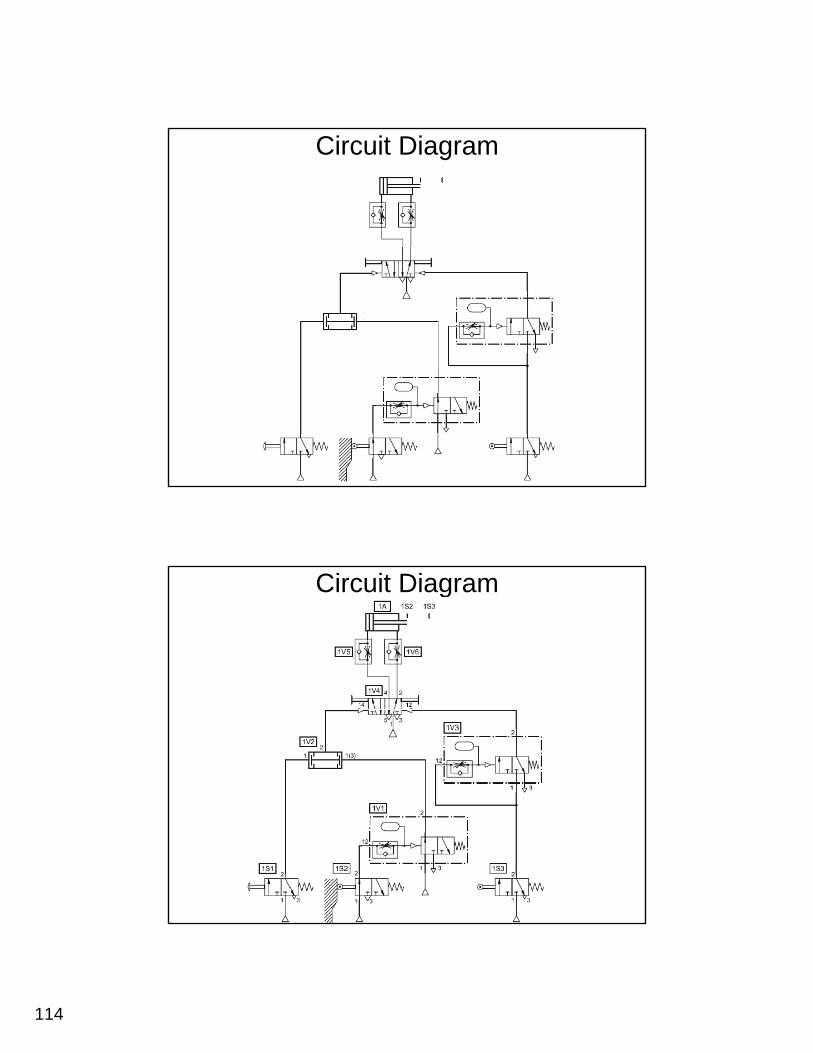
Development of Multiple actuators circuitsControl of multiple actuators
In the case of multiple cylinder circuits, a clear definition of the problem is important. The representation of the desired motion of all actuators is described using the displacement-step diagram. The
i l diti f th t t f th t l bspecial conditions for the start of the sequence must also be defined. If the motion diagram and auxiliary conditions have been clearly defined, drawing of the circuit diagram can commence. In order for a circuit to operate, it is essential to avoid overlapping signals. By an overlapping signal, we understand signals applied simultaneously at the two control ports of a double pilot valve. The following valves can be used to eliminate signal overlap:
ll l l i h idl l l l iroller lever valves with idle return or toggle lever valves, time delay valves, reversing valves or sequencers. To provide a better understanding of the methods, some examples are given for the use of roller lever valves with idle return and reversing valves.
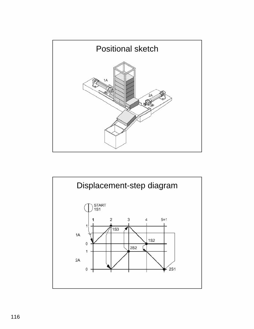
Example 17: Coordinated motion
Two cylinders are used to transfer parts from a magazine onto a chute. When a push button is
d th fi t li d t d hi th tpressed, the first cylinder extends, pushing the part from the magazine and positions it in preparation for transfer by the second cylinder onto the out feed chute. Once the part is transferred, the first cylinder retracts, followed by the second. Confirmation of all extended and retracted positions are required.
116
Positional sketch
Displacement-step diagram
117
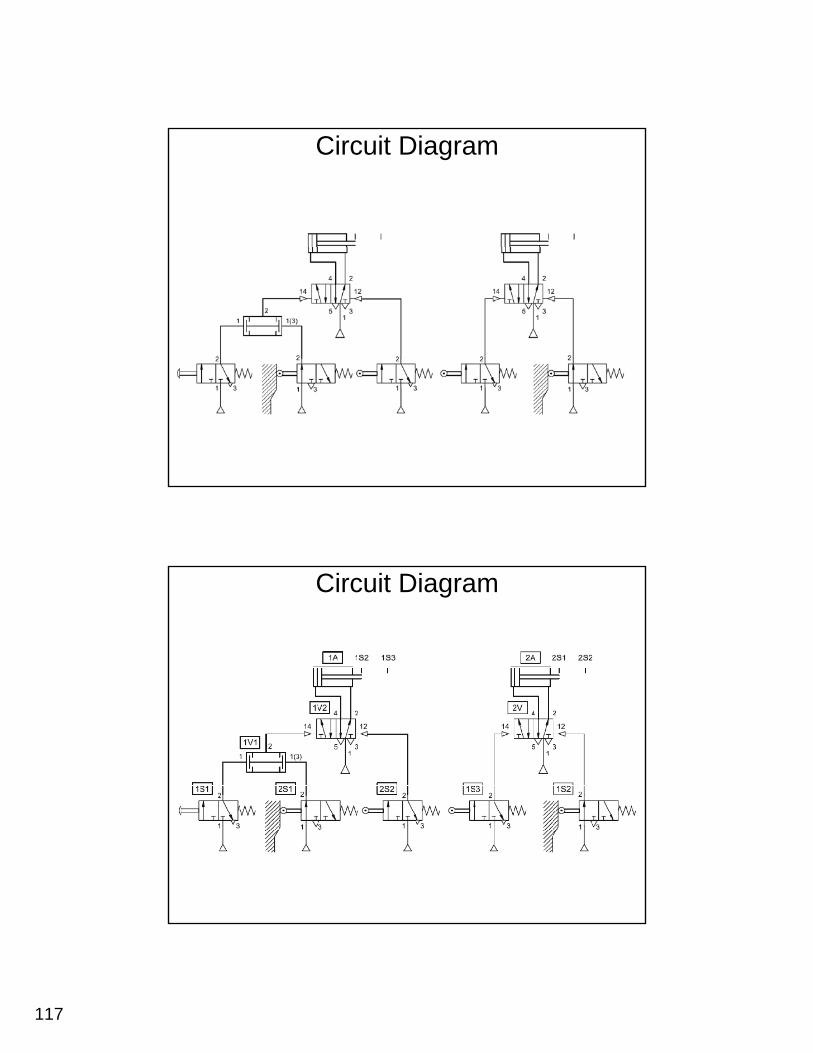
Circuit Diagram
Circuit Diagram
118
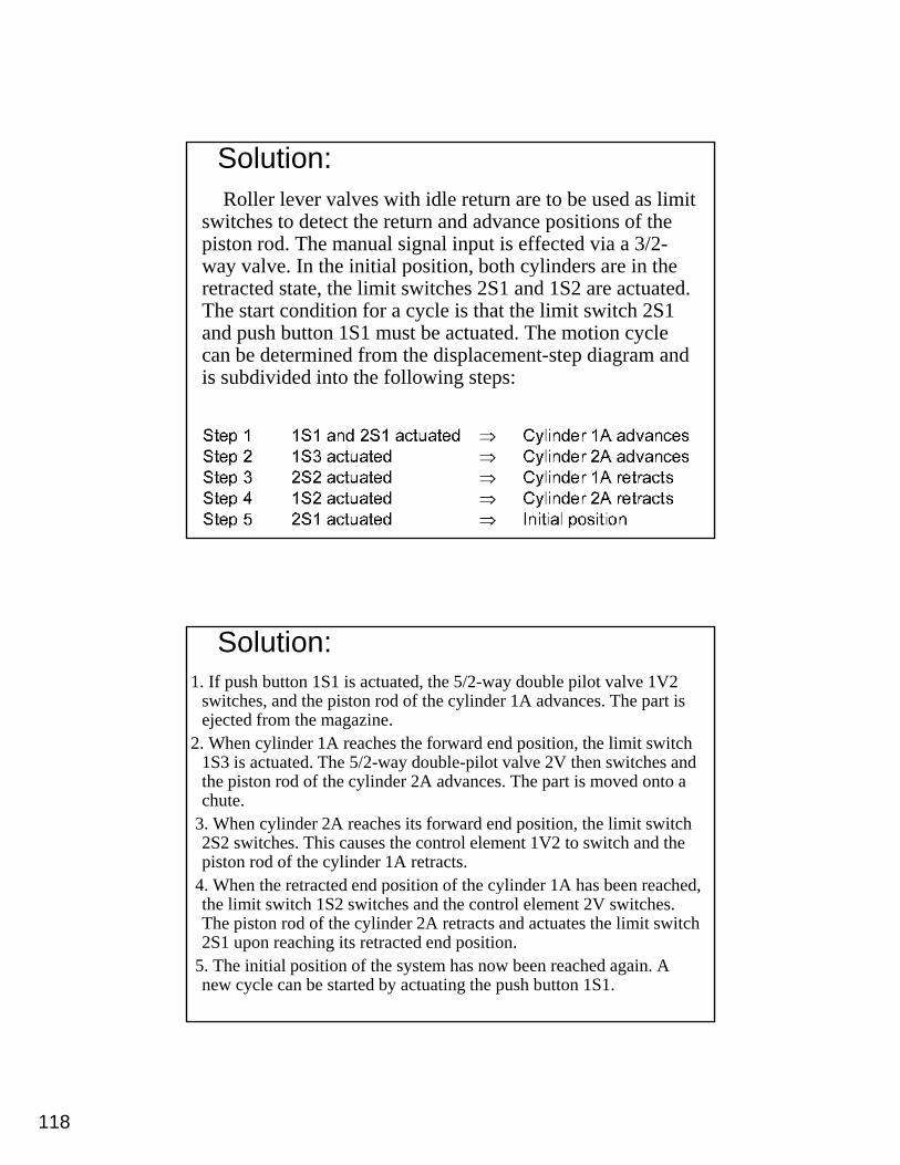
Solution:Roller lever valves with idle return are to be used as limit
switches to detect the return and advance positions of the piston rod. The manual signal input is effected via a 3/2-way valve. In the initial position, both cylinders are in the y p , yretracted state, the limit switches 2S1 and 1S2 are actuated. The start condition for a cycle is that the limit switch 2S1 and push button 1S1 must be actuated. The motion cycle can be determined from the displacement-step diagram and is subdivided into the following steps:
Solution:1. If push button 1S1 is actuated, the 5/2-way double pilot valve 1V2
switches, and the piston rod of the cylinder 1A advances. The part is ejected from the magazine.
2. When cylinder 1A reaches the forward end position, the limit switch 1S3 i t t d Th 5/2 d bl il t l 2V th it h d1S3 is actuated. The 5/2-way double-pilot valve 2V then switches and the piston rod of the cylinder 2A advances. The part is moved onto a chute.
3. When cylinder 2A reaches its forward end position, the limit switch 2S2 switches. This causes the control element 1V2 to switch and the piston rod of the cylinder 1A retracts.
4. When the retracted end position of the cylinder 1A has been reached,4. When the retracted end position of the cylinder 1A has been reached, the limit switch 1S2 switches and the control element 2V switches. The piston rod of the cylinder 2A retracts and actuates the limit switch 2S1 upon reaching its retracted end position.
5. The initial position of the system has now been reached again. A new cycle can be started by actuating the push button 1S1.
119
Diff t P tiDifferent Pneumatic Circuits
120
121
122
123
124
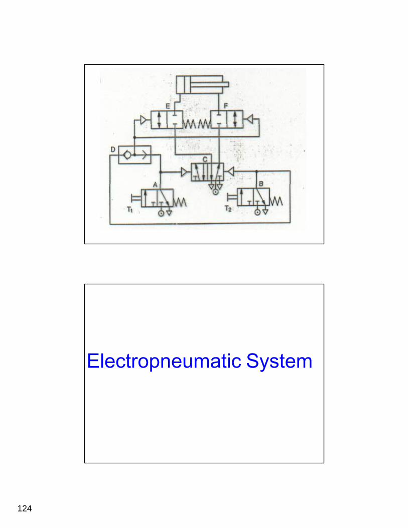
Electropneumatic System
125
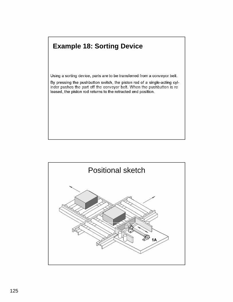
Example 18: Sorting Device
Positional sketch
126
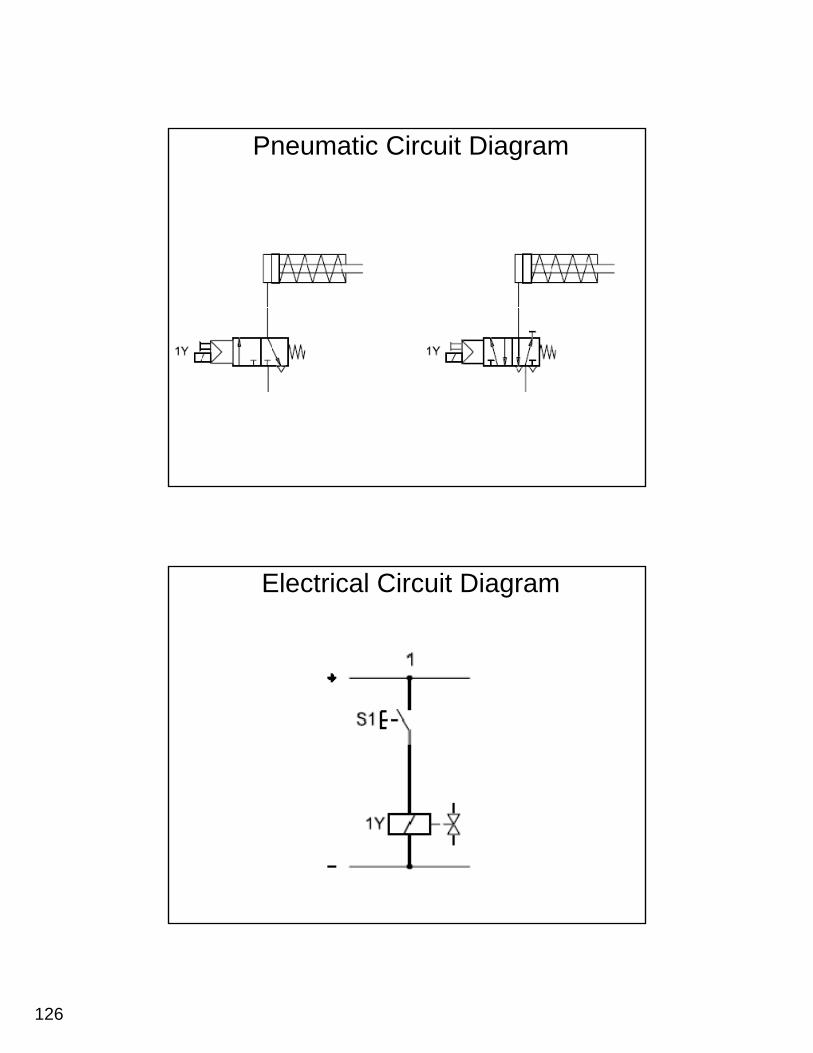
Pneumatic Circuit Diagram
Electrical Circuit Diagram
127
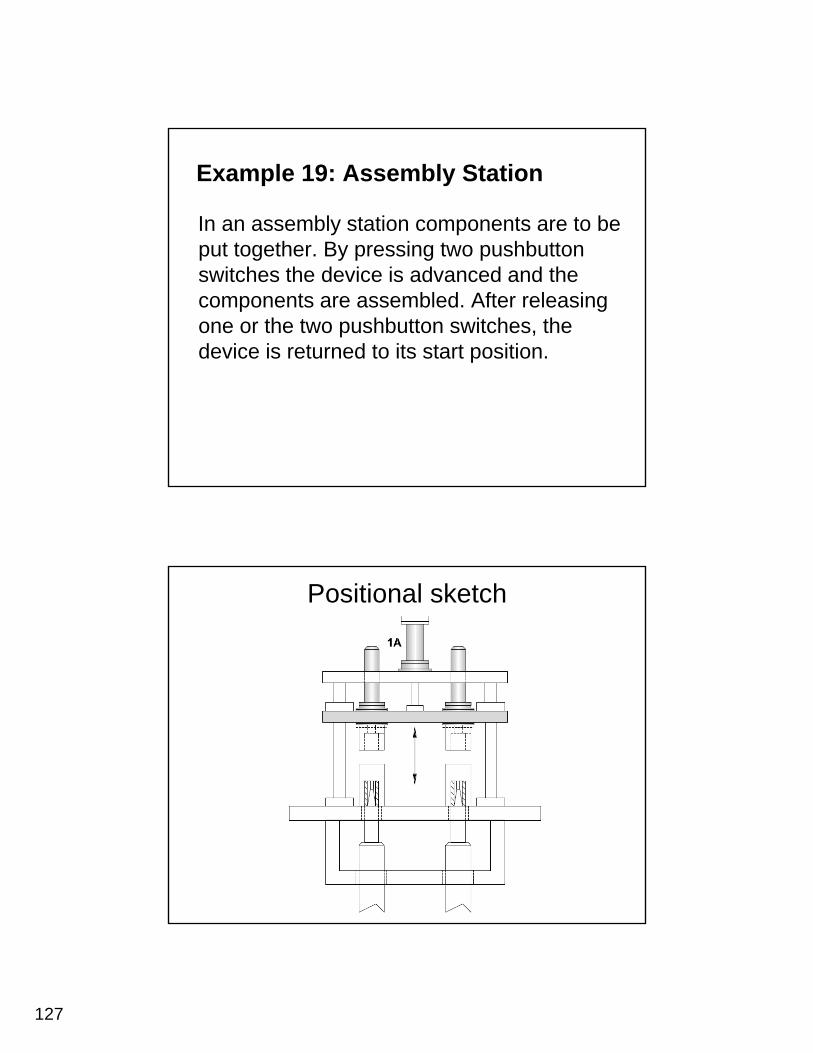
Example 19: Assembly Station
In an assembly station components are to be put together By pressing two pushbuttonput together. By pressing two pushbutton switches the device is advanced and the components are assembled. After releasing one or the two pushbutton switches, the device is returned to its start position.
Positional sketch
128
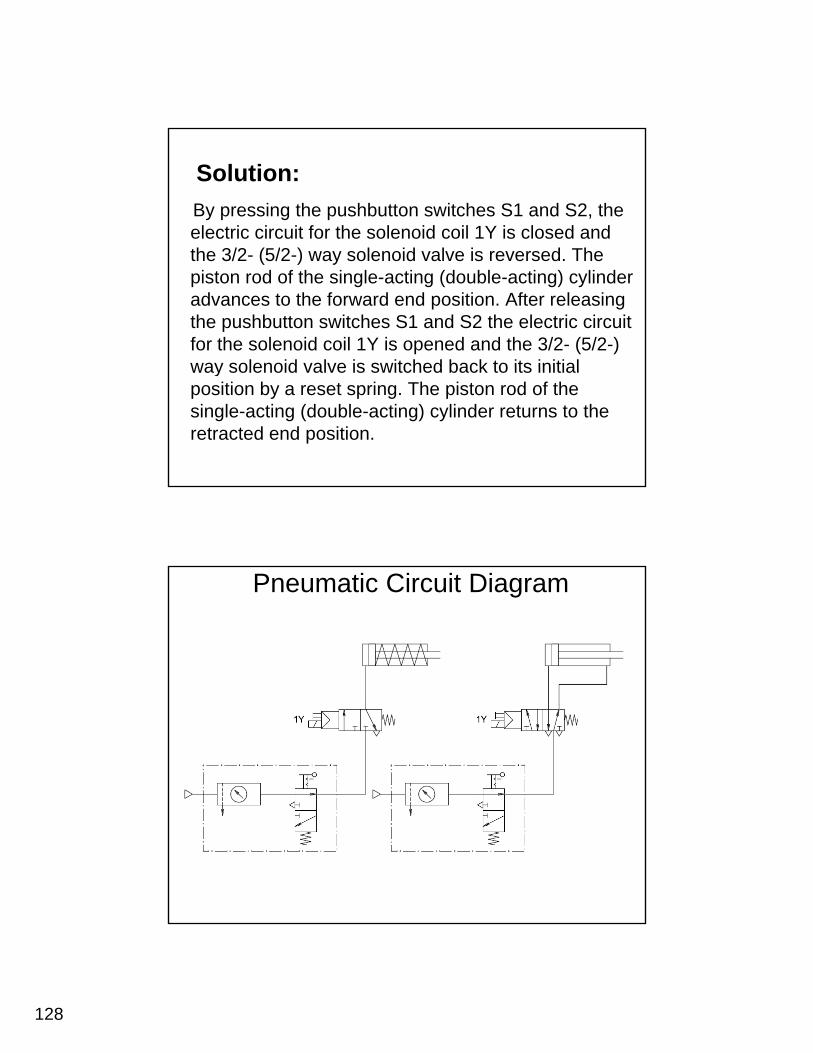
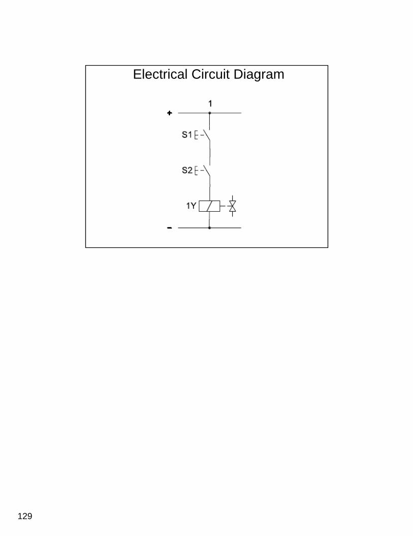
Solution:By pressing the pushbutton switches S1 and S2, the electric circuit for the solenoid coil 1Y is closed and
3/2 ( /2 )the 3/2- (5/2-) way solenoid valve is reversed. The piston rod of the single-acting (double-acting) cylinder advances to the forward end position. After releasing the pushbutton switches S1 and S2 the electric circuit for the solenoid coil 1Y is opened and the 3/2- (5/2-) way solenoid valve is switched back to its initialway solenoid valve is switched back to its initial position by a reset spring. The piston rod of the single-acting (double-acting) cylinder returns to the retracted end position.
Pneumatic Circuit Diagram
129
Electrical Circuit Diagram