Pneumatic Fender solutions with market leading service · PDF filePneumatic Fender solutions...
13
Pneumatic Fenders from Trelleborg and Teekay Pneumatic Fender solutions with market leading service and support
Transcript of Pneumatic Fender solutions with market leading service · PDF filePneumatic Fender solutions...

P n e u m a t i c F e n d e r s f r o m Tr e l l e b o r g a n d Te e ka y
P n e u m a t i c F e n d e r s o l u t i o n s w i t h m a r ke t l e a d i n g s e r v i c e a n d s u p p o r t
1
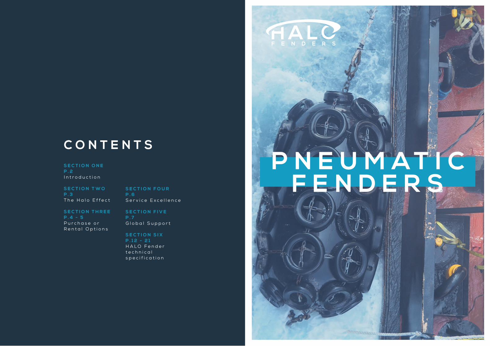
C O N T E N T SS E C T I O N O N EP . 2 I n t r o d u c t i o n
S E C T I O N T W OP . 3 T h e H a l o E f f e c t
S E C T I O N T H R E EP . 4 - 5 P u r c h a s e o r R e n t a l O p t i o n s
S E C T I O N F O U RP . 6 S e r v i c e E x c e l l e n c e
S E C T I O N F I V EP . 7G l o b a l S u p p o r t
S E C T I O N S I XP . 1 2 - 2 1H A L O F e n d e r t e c h n i c a l s p e c i f i c a t i o n
P N E U M A T I CF E N D E R S
2 3
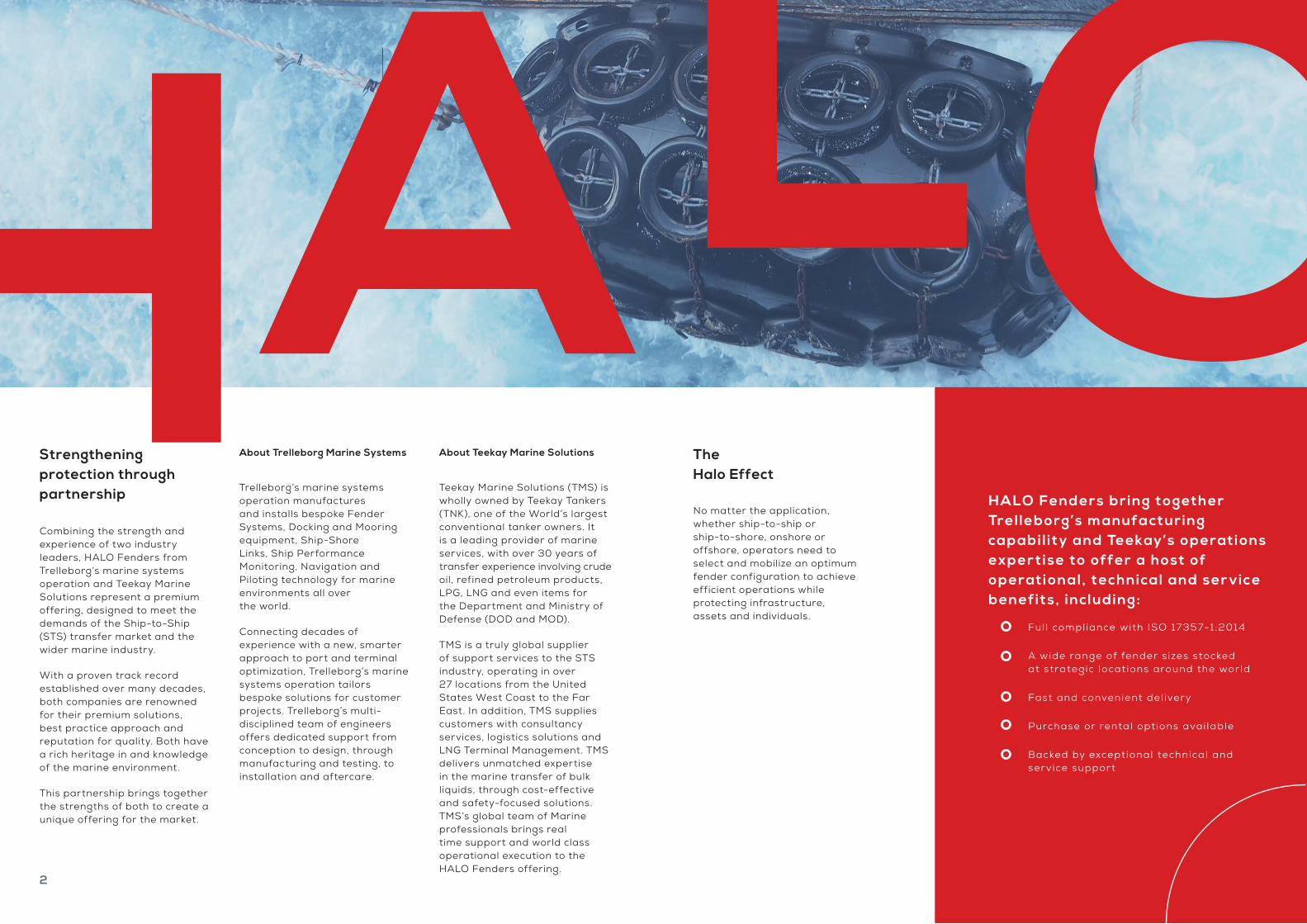
Strengthening protection through partnership
Combining the strength and experience of two industry leaders, HALO Fenders from Trelleborg’s marine systems operation and Teekay Marine Solutions represent a premium offering, designed to meet the demands of the Ship-to-Ship (STS) transfer market and the wider marine industry.
With a proven track record established over many decades, both companies are renowned for their premium solutions, best practice approach and reputation for quality. Both have a rich heritage in and knowledge of the marine environment.
This partnership brings together the strengths of both to create a unique offering for the market.
About Trelleborg Marine Systems
Trelleborg’s marine systems operation manufactures and installs bespoke Fender Systems, Docking and Mooring equipment, Ship-Shore Links, Ship Performance Monitoring, Navigation and Piloting technology for marine environments all over the world.
Connecting decades of experience with a new, smarter approach to port and terminal optimization, Trelleborg’s marine systems operation tailors bespoke solutions for customer projects. Trelleborg’s multi-disciplined team of engineers offers dedicated support from conception to design, through manufacturing and testing, to installation and aftercare.
About Teekay Marine Solutions
Teekay Marine Solutions (TMS) is wholly owned by Teekay Tankers (TNK), one of the World’s largest conventional tanker owners. It is a leading provider of marine services, with over 30 years of transfer experience involving crude oil, refined petroleum products, LPG, LNG and even items for the Department and Ministry of Defense (DOD and MOD).
TMS is a truly global supplier of support services to the STS industry, operating in over 27 locations from the United States West Coast to the Far East. In addition, TMS supplies customers with consultancy services, logistics solutions and LNG Terminal Management. TMS delivers unmatched expertise in the marine transfer of bulk liquids, through cost-effective and safety-focused solutions. TMS’s global team of Marine professionals brings real time support and world class operational execution to the HALO Fenders offering.
The Halo Effect
No matter the application, whether ship-to-ship or ship-to-shore, onshore or offshore, operators need to select and mobilize an optimum fender configuration to achieve efficient operations while protecting infrastructure, assets and individuals.
HA LO Fend ers bring together Trel leborg’s manufa cturing capabi l it y and Teekay’s operati ons exper tise to offer a host of operati onal , technical and ser vic e benefits, including:
Ful l compliance with ISO 17357-1:2014
A wide range of fender s izes stocked at strategic locations around the world
Fast and convenient del ivery
Purchase or rental options avai lable
Backed by exceptional technical and service support

4 5
C ommercial F lexibi l i t y
HALO Fenders’ unique offering extends to enhanced commercial support.
The HALO Fenders offering includes options to either buy or rent fenders, so that operators can align solutions to their operations and financial situation, selecting whichever option best fits their overall needs.
Customers can buy or rent from globally available stock.
Rental can either be on a long or short-term basis.
HALO Fenders also offers a ‘buy-back’ option, and in select cases customers can even buy previously used fenders.
If a bespoke fender size or type is required, the Trelleborg factory will design and manufacture a project-specific solution in a timely and cost-effective way.
This commercial flexibility is intended to help owners and operators maintain efficient logistics and improve supply chain excellence, while ensuring the highest quality standards to operate safely and efficiently.
Purchase orRental options

6 7
Unique servicing and support
Both Trelleborg and Teekay are committed to providing the highest quality standards, to ensure safe and efficient transfer operations, from product supply to supporting services.
The HALO Fender offering provides customers with a single point of contact for consulting and supply, from product specification, to delivery, through to comprehensive field services.
Support services include:
Fender selection
Specification advice
Chain Tire Net fitting
Mobilization
Certification & documentation
Maintenance & repair
Support wherever you need it
Whatever the cargo being transferred, ship-to-ship mooring demands exceptional levels of safety, reliability and responsiveness to guarantee efficient and cost-effective operations across the world.
That means selecting and maintaining an appropriate fender system, and being able to mobilize it quickly. With HALO Fenders, we hold new stock in three strategic locations, ensuring fast global delivery through our comprehensive transport and logistics network. We also have 32 rental and service bases with global access to 400 fenders to ensure we can provide fast, local maintenance and repair.
Locations
Key Stock Locations //China //USA //Middle East

8 9
3
32400
HALO Fenders are fully compliant with ISO 17357-1:2014
Faster, safer mobilization of premium pneumatic fender systems via:
strategic stock locations
rental and service bases
fenders
global access to

1 0 1 1
Pneumatic rubber fenders are ideal for permanent and semi-permanent port and ship-to-ship transfers
Features
Easy and fast to deploy
Very low reaction and hull pressure
Suitable for small and large tidal ranges
Maintains large clearances between hull and structure
ISO 17357-1:2014 compliant
Applications
Oil and gas tankers
Fast ferries and aluminum vessels
Temporary and permanent installations
Rapid response and emergencies
Fast and easy to deploy, the ISO 17357-1:2014 compliant HALO Fenders ensure clearance is maintained between the hull and jetty or other vessels. Risk of damage during mooring is minimized, protecting people and cargo.
HALO Fenders require minimal maintenance, so costs are kept down. Constructed of several layers of thick rubber and strong tire cord
reinforcement, they will not deteriorate under cyclic loads and a high level of buoyancy is maintained. Air has consistent elasticity and compressibility, ensuring continual performance.
HALO Fenders are ideal for permanent and semi-permanent port and ship-to-ship transfers. They support berthing at angles up to 15 degrees for advanced vessel types such as
ULCC, FLNG, FSRU, FSU, FSO, FPSO, LNG and bulk carriers. Due to the hollow construction, these fenders are lighter and easier to handle than solid rubber models.
The new design meets even the harshest conditions and toughest challenges. All products are manufactured by Trelleborg in-house, ensuring full control over quality at every stage of production.
C
H
I
N
A
U
A
E
U
S
A
Three strategic stock locations

1 2 1 3
Construction
ISO standard
HALO Fenders are manufactured and third party certified in compliance with ISO 17357-1:2014. The stringent requirements of this standard ensure that fenders are of a high quality and can withstand the rigorous environments and applications they are designed to operate in. ISO 17357-1:2014 details three major elements of construction: the outer rubber, tire-cord reinforcing layer and the inner rubber.
Outer rubber
The tough abrasion resistant outer rubber is designed to protect the inner rubber and tire-cord layers from damaging external forces. The material has mechanical properties to withstand the arduous operational conditions for which it is designed. The diagram below shows the actual properties as specified in ISO 17357-1:2014. Generally, the outer rubber is black, but other colors such as grey and off-white can be supplied upon request.
Tire-cord layer
Synthetic tire-cord layers have proven to be the best option for strong, efficient reinforcement for pneumatic rubber fenders. Each layer is coated with a rubber compound on both sides that prevents contact between the layers, reducing friction and wear during bending, compression and stretching.
The same compound isolates each thread within the layer. This greatly improves the ability of the fender to hold pressure, fatigue resistance and endurance life. Other reinforcing layer materials such as canvas have wear points that significantly reduce the life of the fender. A schematic of the construction is shown below.
Inner rubber
The inner rubber seals pressurized air inside the fender. It is usually constructed of a compound similar to that of an inner tube in a truck or car tire to ensure a good level of air tightness.
The main elements of HALO Fender construction.
The number of tire-cord layers is dependent on the application.
The material tests of the outer and inner rubber shall be conducted in accordance with the specification given in the table below.
Outer and inner rubber material properties requirements
NOTE: if the color of the outer rubber is not black, the material requirements will differ from those in this table.
1 pphm: parts of ozone per hundred million of air by volume.
Properties of the inner and outer rubber as adapted from ISO 17357-1:2014 Ships and Marine Technology -High-pressure Floating Pneumatic Rubber Fenders.
Construction of tire-cord layers as adapted from ISO 17357-1:2014.
1 Warp threads that run vertically through the synthetic tire-cord pattern.
2 Weft threads that run perpendicular to the warp threads.
1
1 2
2
TEST ITEM TEST METHOD
REQUIRED VALUEOUTER RUBBER INNER RUBBER
Before ageing Original Original
Tensile strength BS ISO 37 18 MPa or more 10 MPa or more
Elongation BS ISO 37 400% or more 400% or more
Hardness ISO 7619 60 +/- 10 (durometer hardness test type A)
50 +/- 10 (durometer hardness test type A)
After ageing ISO 188 Air oven ageing. 70ºC +/- 1ºC. 96 h
Air oven ageing. 70ºC +/- 1ºC. 96 h
Tensile strength BS ISO 37 Not less than 80% of the original property
Not less than 80% of the original property
Elongation BS ISO 37 Not less than 80% of the original property
Not less than 80% of the original property
Hardness ISO 7619 Not to exceed the original property by more than 8
Not to exceed the original property by more than 8
Tear BS ISO 34-1 400 N/cm or more No requirement
Compression set ISO 815 30% (70ºC +/-1ºC for 22h ) or less No requirement
Static ozone resistance
ISO 1431-1 No cracks after elongation by 20% and exposure to 50 pphm1 at 40ºC for 96 h. No requirement

1 4 1 5
Regardless of type or pressure, fenders are measured by diameter and length, generally expressed in millimeters (mm). Type I (chain-tire net) fenders
are not available below 800 x 1200. All fenders with diameter 2500 mm and above are fitted with a pressure relief valve in accordance with ISO 17357-1:2014.
Standard sizes
Non-standard sizes
Some applications may require sizes outside of those specified in the standards. Trelleborg Marine Systems can customize fenders to meet your specifications.
SIZE (OD X L) (mm) BODY MASS (kg) CTN MASS (kg) TOTAL MASS (kg) CHAIN (mm)
500 × 1000 35 – 35 13
1000 × 1500 140 170 310 16
1000 × 2000 ^ 170 200 370 16
1200 × 2000 200 220 420 18
1350 × 2500 270 260 530 20
1500 × 3000* 350 440 790 22
2000 × 3500* 650 920 1570 28
2500 × 4000 1100 1510 2610 32
2500 × 5500* 1350 1620 2970 36
3300 × 4500 1800 2360 4160 38
3300 × 6500 ^ 2250 3120 5370 44
3300 × 10600 2800 4050 6850 48
4500 × 9000* 4950 6200 11150 50
SIZE (OD X L) (mm) SIZE (OD X L) (mm)
300 × 500 1700 × 3000
300 × 600 1700 × 7200
500 × 800 2000 × 3000
800 × 1200 2000 × 6000
800 × 1500 3000 × 5000
1200 × 1800 4500 × 7000
1500 × 2500
^Fast deliveries available ex-stock from China, USA and Middle East
*Fast deliveries available ex-stock from China
3300 x 4500 and 4500 x 7000 and other bespoke sizes are available on request.
Product characteristics
INITIAL INTERNAL PRESSURE 50kPa 80kPa
NOMINAL SIZE DIAMETER × LENGTH
(mm)
GUARANTEED ENERGY
ABSORPTION (GEA)
REACTION FORCE AT GEA
DEFLECTION(R)
HULL PRESSURE (INTERNAL
PRESSURE) AT GEA
DEFLECTION (P)
GUARANTEED ENERGY
ABSORPTION (GEA)
REACTION FORCE AT GEA
DEFLECTION(R)
HULL PRESSURE (INTERNAL
PRESSURE) AT GEA
DEFLECTION (P)
MINIMUM VALUE AT
DEFLECTION 60 ± 5 %
kj
TOLERANCE ±10 %
kN
REFERENCE VALUEkPa
MINIMUM VALUE AT
DEFLECTION 60 ± 5 %
kj
TOLERANCE ±10 %
kN
REFERENCE VALUE
kPa
500 x 1000 6 64 132 8 85 1741000 x 1500 32 182 122 45 239 1601000 x 2000 45 257 132 63 338 1741200 x 2000 63 297 126 88 390 1661350 x 2500 102 427 130 142 561 1701500 x 3000 153 579 132 214 761 1742000 x 3500 308 875 128 430 1150 1682500 x 4000 663 1381 137 925 1815 1802500 x 5500 943 2019 148 1317 2653 1953300 x 4500 1175 1884 130 1640 2476 1713300 x 6500 1814 3015 146 2532 3961 1913300 x 10600 3067 5257 158 4281 6907 2084500 x 9000 4752 5747 146 6633 7551 192
Performance data
Performance Curve
Deflection %
0 10 20 30 40 50 60 70
Rea
ctio
n fo
rce
(kN
)
Inne
r p
ress
ure
(hul
l pre
ssur
e) (k
Pa)
Ene
rgy
abso
rptio
n (k
J)
Reaction force Energy absorption Inner pressure
1 Reaction force at GEA deflection
2 Guarantee energy absorption (GEA)
3 Hull pressure at GEA deflection
4 GEA deflection
1
2
4
3
1 6 1 7
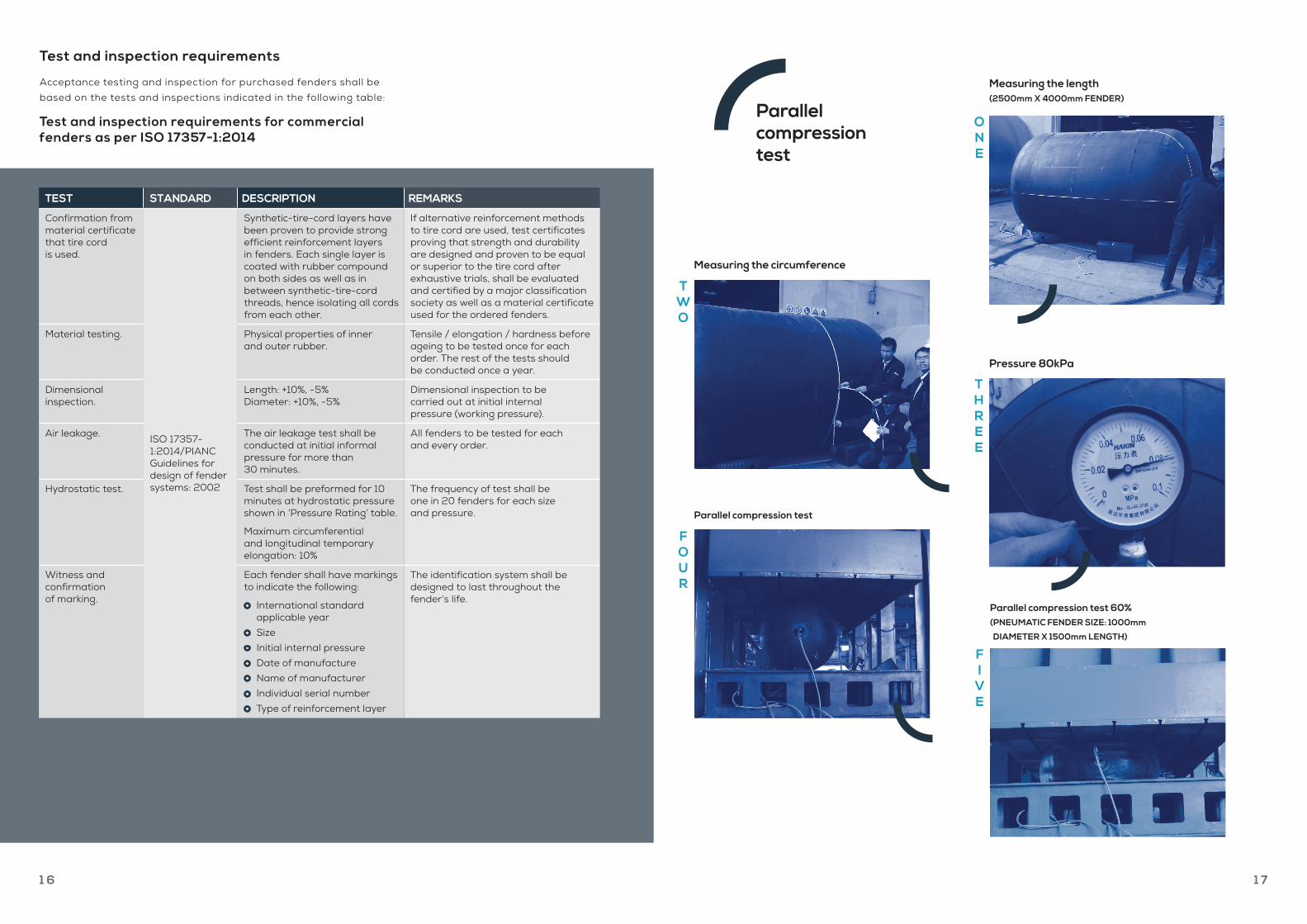
Test and inspection requirements
Acceptance testing and inspection for purchased fenders shall be based on the tests and inspections indicated in the following table:
Test and inspection requirements for commercial fenders as per ISO 17357-1:2014
TEST STANDARD DESCRIPTION REMARKS
Confirmation from material certificate that tire cord is used.
ISO 17357-1:2014/PIANC Guidelines for design of fender systems: 2002
Synthetic-tire-cord layers have been proven to provide strong efficient reinforcement layers in fenders. Each single layer is coated with rubber compound on both sides as well as in between synthetic-tire-cord threads, hence isolating all cords from each other.
If alternative reinforcement methods to tire cord are used, test certificates proving that strength and durability are designed and proven to be equal or superior to the tire cord after exhaustive trials, shall be evaluated and certified by a major classification society as well as a material certificate used for the ordered fenders.
Material testing. Physical properties of inner and outer rubber.
Tensile / elongation / hardness before ageing to be tested once for each order. The rest of the tests should be conducted once a year.
Dimensional inspection.
Length: +10%, -5% Diameter: +10%, -5%
Dimensional inspection to be carried out at initial internal pressure (working pressure).
Air leakage. The air leakage test shall be conducted at initial informal pressure for more than 30 minutes.
All fenders to be tested for each and every order.
Hydrostatic test. Test shall be preformed for 10 minutes at hydrostatic pressure shown in ‘Pressure Rating’ table.
Maximum circumferential and longitudinal temporary elongation: 10%
The frequency of test shall be one in 20 fenders for each size and pressure.
Witness and confirmation of marking.
Each fender shall have markings to indicate the following:
International standard applicable year
Size Initial internal pressure Date of manufacture Name of manufacturer Individual serial number Type of reinforcement layer
The identification system shall be designed to last throughout the fender’s life.
Measuring the length (2500mm X 4000mm FENDER)
Measuring the circumference
Parallel compression test
Pressure 80kPa
Parallel compression test 60% ( PNEUMATIC FENDER SIZE: 1000mm
DIAMETER X 1500mm LENGTH)
ONE
TWO
THREE
FI
VE
FOUR
Parallel compression test

1 8 1 9
Pressure ratings
Trelleborg Marine Systems manufactures fenders with two initial pressures: 50 kPa (Pneumatic 50) and 80 kPa (Pneumatic 80). Design values are given below.
Types of fenders
There are two basic types of pneumatic fenders that comply with the international standard ISO 17357-1:2014: Type I (net type) and Type II (sling type). The most appropriate type for a given application is dependent on how the fender is used and the facility’s requirements.
Type I
Type I fenders are fitted with a chain-tire net (CTN). This is a lattice of used tires connected by a network of horizontal and vertical chains, which adds further protection to the fender body. The chains are galvanized for greater corrosion resistance and covered
by rubber sleeves to prevent abrasive damage to the outer rubber. The horizontal chains are fastened at each end to a tow ring. CTNs are not available for fender sizes below 800 x 1200 mm.
Type I fenders are the most common in use.
Type II
Sling or hook type fenders are effectively a Type I fender without the CTN and the tow ring. A lifting eye is fitted to each end and the fender is slung by chain or wire rope. Type II fenders are available across the whole size range.
Type II fender showing the lifting eyes at both ends
CTN chains connected to the tow ring on a Type I fender
TWO
FOUR
Type I fender showing the chain-tire net (CTN)
Type II fender in operation
ONE
THREE
PNEUMATIC 50SIZE (OD x L)
(mm)
INTERNAL PRESSURE (kPa) MIN. ENDURABLE PRESSURE (kPa) SAFETY VALVEPRESSURE
SETTING (kPa)
TEST PRESSURE AT 0%
DEFLECTION (kPa)AT 0%
DEFLECTIONAT 60%
DEFLECTIONAT 0%
DEFLECTIONAT 60%
DEFLECTION
500 x 1000 50 132 300 462 – 200
1000 x 1500 50 122 300 427 – 200
1000 x 2000 50 132 300 462 – 200
1200 x 2000 50 126 300 441 – 200
1350 x 2500 50 130 300 455 – 200
1500 x 3000 50 132 300 462 – 200
2000 x 3500 50 128 300 448 – 200
2500 x 4000 50 137 350 480 175 250
2500 x 5500 50 148 350 518 175 250
3300 x 4500 50 130 350 455 175 250
3300 x 6500 50 146 350 511 175 250
3300 x 10600 50 158 350 553 175 250
4500 x 9000 50 146 350 511 175 250
PNEUMATIC 80SIZE (OD x L)
(mm)
INTERNAL PRESSURE (kPa) MIN. ENDURABLE PRESSURE (kPa) SAFETY VALVEPRESSURE
SETTING (kPa)
TEST PRESSURE AT 0%
DEFLECTION (kPa)AT 0%
DEFLECTIONAT 60%
DEFLECTIONAT 0%
DEFLECTIONAT 60%
DEFLECTION
500 x 1000 80 174 480 609 – 250
1000 x 1500 80 160 480 560 – 250
1000 x 2000 80 174 480 609 – 250
1200 x 2000 80 166 480 581 – 250
1350 x 2500 80 170 480 595 – 250
1500 x 3000 80 174 480 609 – 250
2000 x 3500 80 168 480 588 – 250
2500 x 4000 80 180 560 630 230 300
2500 x 5500 80 195 560 683 230 300
3300 x 4500 80 171 560 599 230 300
3300 x 6500 80 191 560 669 230 300
3300 x 10600 80 208 560 728 230 300
4500 x 9000 80 192 560 672 230 300

2 0 2 1
End fittings
Pneumatic fenders are often suspended using chains, shackles. Recommended dimensions of the standard fittings are given in the table below.
Installation dimensions
Pneumatic fenders must be installed onto a solid structure or reaction panel to ensure that they are properly supported during impacts.
[Units: mm]
W
Lowest lower water level (LLWL)
Tidal range
Highest Higher water level (HHWL)C A
D
E
B
TYPE 2 FENDER (SLING)FIRST SHACKLE DIAMETER mm
(inch)
SWIVEL DIAMETER mm (inch)
OTHER SHACKLE
DIAMETER mm (inch)
GUY ROPE DIAMETER mm (inch)
GUY CHAIN DIAMETER mm (inch)
ANCHOR DIAMETER mm (inch)
SIZE (OD X L) (mm)
INITIAL PRESSURE
(kPa)1000 x 1500 50 19 (3/4) 19 (3/4) 19 (3/4) 16 (5/8) 16 (5/8) 25 (1)
1000 x 2000 50 19 (3/4) 19 (3/4) 19 (3/4) 16 (5/8) 16 (5/8) 25 (1)
1200 x 1800 50 19 (3/4) 19 (3/4) 19 (3/4) 16 (5/8) 16 (5/8) 25 (1)
1200 x 2000 50 19 (3/4) 19 (3/4) 19 (3/4) 16 (5/8) 16 (5/8) 25 (1)
1350 x 2500 50 22 (7/8) 22 (7/8) 22 (7/8) 18 (11/16) 16 (5/8) 25 (1)
1500 x 2500 50 22 (7/8) 22 (7/8) 22 (7/8) 20 (13/16) 19 (3/4) 32 (1-1/4)
1500 x 3000 50 22 (7/8) 22 (7/8) 22 (7/8) 20 (13/16) 19 (3/4) 32 (1-1/4)
1700 x 3000 50 25 (1) 25 (1) 25 (1) 24 (15/16) 22 (7/8) 32 (1-1/4)
2000 x 3000 50 25 (1) 25 (1) 25 (1) 24 (15/16) 22 (7/8) 32 (1-1/4)
2000 x 3500 50 25 (1) 25 (1) 25 (1) 24 (15/16) 22 (7/8) 32 (1-1/4)
2000 x 6000 50 32 (1-1/4) 32 (1-1/4) 32 (1-1/4) 30 (1-3/16) 26 (1) 36 (1-7/16)
2500 x 4000 50 32 (1-1/4) 32 (1-1/4) 32 (1-1/4) 30 (1-3/16) 26 (1) 42 (1-5/8)
2500 x 5500 50 32 (1-1/4) 32 (1-1/4) 32 (1-1/4) 34 (1-3/8) 32 (1-1/4) 44 (1-3/4)
3000 x 5000 50 38 (1-1/2) 38 (1-1/2) 38 (1-1/2) 34 (1-3/8) 30 (1-3/16) 44 (1-3/4)
3300 x 4500 50 44 (1-3/4) 38 (1-1/2) 44 (1-3/4) 34 (1-3/8) 30 (1-3/16) 44 (1-3/4)
3300 x 6500 50 44 (1-3/4) 38 (1-1/2) 44 (1-3/4) 42 (1-5/8) 38 (1-1/2) 55 (2-3/16)
4500 x 9000 50 44 (1-3/4) (2 Qty) 44 (1-3/4) 44 (1-3/4) 42 (1-5/8) 38 (1-1/2) 55 (2-3/16)
CHAIN TIRE NET (CTN) FENDERS
FENDER SIZEA B C D E W
DIAMETER LENGTH
1000 1500 825 940 1340 345 515 1950
1200 2000 1100 1130 1610 305 510 2600
1500 2500 1485 1410 2010 270 525 3250
2000 3500 1965 1880 2680 375 715 4550
2500 4000 2495 2355 3355 430 855 5200
3300 6500 3365 3110 4430 500 1065 8450
4500 9000 4605 4240 6040 665 1435 11700
SLING FENDERSFENDER SIZE
A B C D E WDIAMETER LENGTH
1000 1500 1020 940 1340 150 320 1950
1200 2000 1265 1130 1610 140 345 2600
1500 2500 1575 1410 2010 180 435 3250
2000 3500 2125 1880 2680 215 555 4550
2500 4000 2675 2355 3355 250 675 5200
3300 6500 3605 3110 4430 260 825 8450
4500 9000 4935 4240 6040 335 1105 11700
Fender Fixing Accessories (50 kPa Initial Pressure)
Fender Fixing Accessories (80 kPa Initial Pressure)
Recommended sizes of shackles and chains for all sizes of Type II fenders.
TYPE 2 FENDER (SLING)FIRST SHACKLE DIAMETER mm
(inch)
SWIVEL DIAMETER mm (inch)
OTHER SHACKLE
DIAMETER mm (inch)
GUY ROPE DIAMETER mm (inch)
GUY CHAIN DIAMETER mm (inch)
ANCHOR DIAMETER mm (inch)
SIZE (OD X L) (mm)
INITIAL PRESSURE
(kPa)1000 x 1500 80 19 (3/4) 19 (3/4) 19 (3/4) 16 (5/8) 16 (5/8) 25 (1)
1000 x 2000 80 19 (3/4) 19 (3/4) 19 (3/4) 18 (11/16) 16 (5/8) 25 (1)
1200 x 1800 80 19 (3/4) 19 (3/4) 19 (3/4) 18 (11/16) 16 (5/8) 25 (1)
1200 x 2000 80 19 (3/4) 19 (3/4) 19 (3/4) 18 (11/16) 16 (5/8) 25 (1)
1350 x 2500 80 22 (7/8) 22 (7/8) 22 (7/8) 20 (13/16) 19 (3/4) 25 (1)
1500 x 2500 80 22 (7/8) 22 (7/8) 22 (7/8) 20 (13/16) 19 (3/4) 32 (1-1/4)
1500 x 3000 80 22 (7/8) 22 (7/8) 22 (7/8) 20 (13/16) 19 (3/4) 32 (1-1/4)
1700 x 3000 80 25 (1) 25 (1) 25 (1) 24 (15/16) 22 (7/8) 32 (1-1/4)
2000 x 3000 80 25 (1) 25 (1) 25 (1) 24 (15/16) 22 (7/8) 36 (1-7/16)
2000 x 3500 80 25 (1) 25 (1) 25 (1) 24 (15/16) 22 (7/8) 36 (1-7/16)
2000 x 6000 80 32 (1-1/4) 32 (1-1/4) 32 (1-1/4) 30 (1-3/16) 26 (1) 42 (1-5/8)
2500 x 4000 80 32 (1-1/4) 32 (1-1/4) 32 (1-1/4) 30 (1-3/16) 26 (1) 42 (1-5/8)
2500 x 5500 80 32 (1-1/4) 32 (1-1/4) 32 (1-1/4) 34 (1-3/8) 32 (1-1/4) 44 (1-3/4)
3000 x 5000 80 38 (1-1/2) 38 (1-1/2) 38 (1-1/2) 34 (1-3/8) 30 (1-3/16) 44 (1-3/4)
3300 x 4500 80 44 (1-3/4) 38 (1-1/2) 44 (1-3/4) 38 (1-1/2) 34 (1-3/8) 50 (2)
3300 x 6500 80 44 (1-3/4) 38 (1-1/2) 44 (1-3/4) 46 (1-13/16) 42 (1-5/8) 60 (2-3/8)
4500 x 9000 80 44 (1-3/4) (2 Qty) 44 (1-3/4) 44 (1-3/4) 42 (1-5/8) 38 (1-1/2) 60 (2-3/8)