PNEUMATIC ARTIFICIAL HEART DRIVING SYSTEM PROVIDING … · i pneumatic artificial heart driving...
30
I NASA TECHNICAL n NOTE PNEUMATIC ARTIFICIAL HEART DRIVING SYSTEM PROVIDING QUASI-STEADY-STATE REGULATION AND PRESSURE WAVEFORM CONTROL by John A. Webb, Jr., Michael J. Crosby, and Miles 0. Dzlstin . - . ; .,? , Lewis Research Center L . i ' NATIONAL AERONAUTICS AND SPACE ADMINISTRATION WASHINGTON, D. C. . FEBRUARY 1971 I- https://ntrs.nasa.gov/search.jsp?R=19710008118 2018-06-16T12:10:43+00:00Z
Transcript of PNEUMATIC ARTIFICIAL HEART DRIVING SYSTEM PROVIDING … · i pneumatic artificial heart driving...
I
NASA TECHNICAL
n
NOTE
PNEUMATIC ARTIFICIAL HEART DRIVING SYSTEM PROVIDING QUASI-STEADY-STATE REGULATION AND PRESSURE WAVEFORM CONTROL
by John A . Webb, Jr., Michael J. Crosby, and Miles 0. Dzlstin . - .; . , ? ,
Lewis Research Center L
. i '
NATIONAL AERONAUTICS AND SPACE ADMINISTRATION WASHINGTON, D. C. . FEBRUARY 1971
I -
https://ntrs.nasa.gov/search.jsp?R=19710008118 2018-06-16T12:10:43+00:00Z
TECH LIBRARY KAFB, NM
1. Report No. . "
2. Government Accession No.
NASA TN D-6171 __ " - - " . . 1 . ~
4. Title and Subtitle PNEUMATIC ARTIFICIAL HEART DRIVING SYS- TEM PROVIDING QUASI-STEADY-STATE REGULATION AND PRESSURE WAVEFORM CONTROL
"" ~- ~ ""
7. Author(s)
John A. Webb, Jr., Michael J. Crosby, and Miles 0. Dustin "~ "" . . "
9. Performing Organization Name and Address - ..
Lewis Research Center National Aeronautics and Space Administration Cleveland, Ohio 44135 ~... - -~
12. Sponsoring Agency Name and Address
National Aeronautics and Space Administration Washington, D. C. 20546
-__- ". . .
15. Supplementary Notes
3. Recipient's Catalog No.
5. Report Date February 1971
6. Performing Organization Code
8. Performing Organization Report No.
E- 5827 IO. Work Unit NO.
72 0- 03 "
11. Contract or Grant No.
13. Type of Report and Period Covered
Technical Note 14. Sponsoring Agency Code
~~
16. Abstract . . . .
The design of an art if icial heart control system for renroducing the vumning and flow regulating functions of the natural heart is presented. The quasi-steady-state characterist ics of the natural hear t are reproduced in an ar t i f ic ia l hear t by means of feedback control. The system also uses a specially designed servovalve to provide adjustable pressure waveforms. Average position drift of the pumping element is minimized by feedback control. An analog com 3uter in the driving sys- tem provides flexible control and monitoring caTabilities.
." ~ " " - .. 17. Key Words (Suggested by Author(s)) 18. Distribution Statement
.~
Heart; Circulatory system; Artificial heart; Heart control; Ventricle; Atrium;
Unclassified - unlimited
Bioengineering
19. Security Classif. (of this report) " . . .
20. Security Classif. (of this page) " . .
Unclassified Unclassified __ _ _ _ _ " - .
For sale by the National Technical Information Service, Springfield, Virginia 22151

I
PNEUMATIC ARTIFICIAL HEART DRIVING SYSTEM PROVIDING QUASI-STEADY-
STATE REGULATION AND PRESSURE WAVEFORM CONTROL
by John A. Webb, Jr., Michael J. Crosby, and Miles 0. Dustin
Lewis Research Center
SUMMARY
The design of an art if icial heart control system for reproducing the pumping and flow regulating functions of the natural heart is presented. The quasi-steady-state reg- ulatory characteristics of the natural heart can be reproduced in an artificial heart by using feedback control. The control system is also capable of duplicating the pressure waveforms of the natural heart by using a specially designed pneumatic servovalve. Any drift in the average position of the art if icial pumping chamber is minimized by control- ling the level of the pressure waveform with a position feedback signal. An analog com- puter is used to provide feedback flexibility and monitoring capabilities for research investigations.
This report includes a physiological section to support the control concepts used for the control system design.
A color motion picture entitled "An Artificial Heart Control System" is available f rom NASA Lewis Research Center for further description of the control system. Its identifying number is C247.
INTRODUCTION
Nearly three quarters of a million Americans die annually of circulatory system disease (ref. 1). Many of these people are under 50 years of age. A significant propor- tion of these could be helped by a suitable total replacement artificial heart. Since the late 1950's r e sea rche r s have been able to build devices for pumping blood in experimen- ta l animals af ter the removal of the natural heart. These devices have kept animals alive for a few hours. In the early devices electric motors and electric solenoids were used to compress plastic pumping chambers (ref. 2). Some of this ear ly ar t i f ic ia l hear t
development was conducted at the Cleveland Clinic, Cleveland, Ohio, under the direc- tion of Dr. Willem J. Kolff.
Discussions of the weight, reliability, and heat rejection problems of these ear ly hearts were held between Clinic physicians, NASA, and other Cleveland area engineers. During these discussions it was determined that compressed air would have certain ad- vantages as an energy transmission medium. It was subsequently demonstrated by the Clinic personnel that pneumatically driven hearts had significant weight and reliability advantages. As the control problems of these pneumatic hearts became important, a cooperative program of technical assistance developed between the Cleveland Clinic and NASA Lewis Research Center. This cooperative program continues under the NASA Technology Utilization Program.
Currently, the problems of providing the control complexity necessary for the rea- sonable support of blood flow, of building power supplies and driving mechanisms small enough to be implatable, and of developing heart materials and configurations that will pump blood atraumatically for years are difficult problems yet to be solved. The driv- ing system described in this report was developed to solve the first of these problems, which is determining the degree of control complexity necessary for an artificial heart. The approach was to build a control system having greater than necessary flexibility, re- liability, accuracy, and speed of response to be used as a research tool for controlling pneumatic sac-type hearts.
This report contains a review of circulatory physiology, the control concepts gener- ated from this physiology, the artificial heart control system design, and the results ob- tained with this system.
HUMAN CIRCULATORY SYSTEM PHYSIOLOGY
To appreciate the function to be performed by the artificial heart, consider the ac- tion of the normal heart indicated in figure 1. Carbon dioxide laden blood returns to the right atrium of the heart from the systemic circulation of the head, trunk, and upper and lower extremities at an average venous pressure of 0.0 mill imeter of mercury gage (mm Hg gage)(O. 0 N/cm gage). The right ventricle pumps this blood into the lungs at an average pressure of 15 mm Hg gage (0.20 N/cm gage) where a mass t ransfer of car - bon dioxide for oxygen takes place through the alveoli membranes. It is important to note that the proper partial pressures must exist in the pulmonary circulation to promote th i s mass t ransfer a t a normal physiological rate.
2 2
Freshly oxygenated blood is then returned to the left atrium of the heart at an aver- age pulmonary venous pressure of about 5 m m Hg gage (0.07 N/cm gage). The left ven- tricle pumps this blood back into the systemic circulation at an average pressure of
2
2
100 m m Hg gage (1 .33 N/cm gage). This pressure is also important since the systemic circulation needs the proper partial pressures to allow oxygen transfer to the tissue through the capillary membranes while tissue waste products are being transferred into the blood for removal by the kidneys or lungs.
2
The instantaneous pressures for the right and left ventricles are also shown in fig- ure 1. The aortic and pulmonary artery pressures are superimposed on the ventricular pressure curve to indicate outflow valve opening and closure. During the filling cycle of the hear t or diastole the ar ter ia l pressure decay is a function of the arterial capacitance and systemic resistance. During systole (ejection) the arterial pressure equals the ven- t r icular pressure minus the pressure drop across the outflow valve (normally a small value since the outflow valve is open).
The average flow ra te of blood through the body's circulation is about 5 . 3 liters per minute (88 cm3/sec) during rest. This flow ra te wil l vary with changing body require- ments. The mechanism by which the heart responds to these changing demands is a re- su l t of complex physiological interactions between central nemous, endocrine, and vas- cular systems which are not completely understood (ref. 1) . Certain aspects of these in- teractions can be graphically interpreted from experimental results as shown in figure 2 , which is taken from reference 3. Animal experiments were used to obtain these data which are scaled to magnitudes of flow and pressure comparable to normal human values.
The venous return curve of figure 2 is found by manipulating average atrial pressure and measuring the average flow entering the atrium from the veins. This curve is the flow characterist ic of the veins in response to a given load pressure at the atrium. The intercept at zero cardiac output indicates the mean systemic pressure. The slope of this curve is determined by systemic resistance. If the systemic resistance changes while the mean systemic pressure remains fixed, the slope of the curve is affected and the curve pivots about the mean systemic pressure point as indicated in the figure. If the mean systemic pressure varies while the systemic resistance remains fixed, the curve moves i ts atrial pressure intercept while retaining its slope.
The cardiac output curve in figure 2 is found by manipulating atrial pressure and measuring average ventricular output flow. This curve is the flow characterist ic curve of the heart and is often referred to as Starling's law of the heart (ref. 4). Since the cardiac output curve is plotted for a constant heart rate, the saturation level of this curve occurs due to complete filling of the ventricle during each cycle. Nervous stimu- lation affects the heart rate which in turn affects this saturation level as indicated in the figure.
Since the average flow into the heart must equal the average flow out of the heart , the intersection of the two curves is the operating point. The venous return curve is re- tained when an artificial heart is used, but the cardiac output curve is replaced by the art if icial heart 's characterist ics.
3
. ".

Reference 5 compares the variation in cardiac output caused by nervous stimulation to the variation caused by shifts in the venous return curve. This reference points out that the dominant factor in the regulation of cardiac output is the venous return curve. This can be seen by inspection of the curves of figure 2. The venous return curve is relatively flat with variations in atrial pressure. The cardiac output curve, however, is quite steep. Thus a small change in the slope o r intercept of the venous return curve can have a greater effect on the system flow rate than a change in the cardiac output curve.
For an artificial heart having a fairly steep but fixed cardiac output curve, any change in body demands for more o r less blood flow will appear as a change in the sys- temic resistance. This change alters the venous return curve and seeks a new operat- ing point at the intersection of the fixed cardiac output curve of the art if icial heart and the new venous return curve presented by the systemic circulation. This makes it pos- sible to take advantage of the inherent regulation provided by the circulatory system.
Venous return regulation also tends to maintain the proper blood volume balance be- tween the systemic and pulmonary circulations. A change in blood volume in the pulmon- ary system wi l l change its venous return pressure to the left heart, thus affecting the mean pulmonary pressure and shifting the venous return curve along the atrial pressure axis as was indicated earlier with a change in mean systemic pressure. This shift in the venous return curve produces a change in the cardiac output of the left ventricle that tends to bring left atrial pressure back toward the original operating point, thus shifting blood volume in o r out of the pulmonary circulation to maintain a steady-state equilib- r ium of blood volume distribution in the body.
These average character is t ics of the heart as illustrated by the curves of figure 2 are termed quasi-steady-state since they occur over a number of heart beats.
PNEUMATIC HEART CONFIGURATION
The pneumatic sac-type artificial hearts consist of a rigid outer casing which houses a flexible diaphram or sac as shown in figure 3. The blood side of the sac has two check valves, much like the natural heart, to maintain unidirectional flow. These valves can be similar in design to any of those being presently used clinically for surgical valve re- placements (ref. 6).
When the outer housing is filled with compressed air the sac e jects blood out the outflow valve. Then a vacuum is applied to exhaust the compressed air and fill the sac through the inflow valve. Thus, a pulsatile flow and pressure is produced that can sim- ulate the flow and pressures of the natural heart.
4

Such a heart could be driven by a simple on-off pneumatic valving arrangement (refs. 7 and 8) which provides square wave approximations to ventricular pressure. For initial studies, however, it is desirable to be able to program the ventricular pressure waveform to determine the effects of various waveshapes on the circulatory system.
CONTROL CONCEPTS
It may not be necessary for a practical artificial heart system to exactly duplicate all of the functions of the natural heart. Yet, if ear ly artificial heart research experi- ments fail because of limited capabilities of the driving system, the reason for failure may be difficult to determine because changes cannot be made to the driving parameters. Thus, successive experiments can fail for identical reasons.
To avoid such failures, the driving system and its subsidiary control system should be designed to have maximum flexibility. This overall system could be used to investi- gate various control concepts, and therefore, eliminate those which appear to be unes- sential. This section discusses the control concepts used as the basis for the driving system design described in this report.
Instantaneous Waveform Considerations
A s shown in figure 1 the pressure experienced in the aorta of a circulatory system with a natural heart is nearly equal to that in the ventricle during the time the outflow valve is open. The waveform of this pressure and i ts duration may be important to proper long term functioning of the circulatory system. To determine the relative im- portance of the pressure waveform in the artificial heart, the driving system was de- signed to provide control of this waveform, allowing the operator to program any de- sired waveshape. This was accomplished by driving a closed loop pneumatic servovalve driven by an electronically produced voltage waveform. This voltage waveform can be programmed to produce the desired pressure waveform at the servovalve.
The ability of an artificial heart driving system to achieve physiological waveforms of output blood flow ra te is complicated by the pressure drops across the pneumatic tube and the artificial heart's check valves. In the sac heart the instantaneous blood flow rate requires an approximately equal air flow rate. An additional flow requirement arises due to the need for compressing the residual volume of gas in the air chamber of the artificial heart. If the pressure waveform is modified at the artificial heart driving line, these high air flow requirements can be met to obtain the desired blood flow wave- form.
5
The extent to which the input pressure waveform has to be modified is considerable. This comes about in part due to the large pressure drop across most artificial heart valves at peak instantaneous flow conditions. This can be .explained with the aid of fig- ure 1. It is noted that at resting conditions the duration of outflow or sys to le is approx- imately one-third of the period of one heartbeat. For the natural heart the flow wave- form is somewhat triangular shaped with a peak value of about eight times the average blood flow rate. This would correspond to a peak instantaneous value of 40 liters per minute (670 cm /sec) at resting conditions. A typical artificial heart valve in its open condition behaves like an orifice; thus, the pressure drop across the valve is propor- tional to the square of the flow rate through the valve. An extrapolation of the informa- tion in reference 6 shows that the ball valves and disk valves tested would produce pres- sure drops of about 50 mm Hg (0.67 N/cm ) at a flow rate of 40 liters per minute 2
(670 cm3/sec).
3
Quasi-Steady-State Regulation Considerations
An artificial heart system should provide a reasonable degree of regulation of blood flow rate averaged over a period of several heartbeats. As indicated in the physiology section, regulation of blood flow rate can be largely accomplished by the body's adjust- ment of venous return pressure. This requires a relatively steep cardiac output curve; specifiqally, slopes of approximately 5 and 1 liter per minute per mm Hg ( 6 . 2 ~ 1 0 and 1.2X10 cm /(N)(sec)) are typical of the natural right and left hearts in the region of the operating point.
3 3 5
Reference 5 shows that many artificial heart systems unfortunately produce a nearly flat flow versus pressure character is t ic . For a sac-type heart driven by a solenoid valve-timer system, which supplies 260 mm Hg gage ( 3 . 5 N/cm gage) on systole and -2 mm Hg gage (-0.03 N/cm gage) on diastole, slopes of 0.12, 0.15, and 0.40 l i ter per minute per mm Hg (150, 190, and 500 cm /(N)(sec)) were observed when ball valves, tear drop valves, and leaflet valves, respectively, were used. The best sensitivity obtained was only one-twelfth that of the natural right heart. This condition can arise from the relatively higher flow resistance of the art if icial heart 's valves, from the st iffness of the plastic or rubber blood pumping diaphram, and from slow evacuation of the air cham- ber through a high resistance air line.
2 2
5
In the case of this driving system, provision was made for correcting these defi- ciencies by feeding back atrial pressure to adjust the amplitude of the air pressure fed into the artificial ventricle. As atrial blood pressure increases, air pressure during diastole is reduced unti l the pressure difference across the inflow valve is great enough to force in the necessary blood volume. Air pressure is also increased during systole
6
as necessary to discharge this increase blood volume through the outflow valve. Adequate quasi-steady-state control of pneumatic sac-type artificial hear ts is com-
plicated by two additional problems - pressure referencing and position balancing. For an ar t i f ic ia l hear t system that is driven from outside the chest a difficulty can
arise from the fact that thoracic pressure fluctuates from about -7 to -15 mm Hg gage (-0.09 to -0.20 N/cm gage) during each cycle of breathing. This pressure is t rans- mitted through the flexible walls of the larger veins to the atrial pressure. Thus, the pressure ax is of the curve of figure 2 must be regarded as a differential pressure ref- erenced to thoracic pressure. In case a n artificial heart system could be built which, like the natural heart, is sensitive to atrial pressure by simple hydraulics but had its driving pressures referenced to atmospheric pressure, this could become a problem. It can be seen from figure 2 that a fluctuation of *4 m m Hg (*0.05 N/cm ) in effective atrial pressure would cause the heart to alternate between cutoff and saturation during each cycle of breathing. In the case of this driving system none of the art if icial hearts used had a high enough sensitivity to atrial pressure through simple hydraulics to cause this kind of problem. Since atrial pressure sensit ivity w a s achieved on a quasi-steady- s ta te basis by the use of an e lectronic pressure t ransducer , the problem could be mini- mized by slowing the fed back signal with a low pass filter. Thus, the fluctuations in a t r ia l pressure were averaged over several cycles of breathing.
2
2
The nature of a fluid actuated sac or piston type blood pump creates an additional driving system problem that cannot be overlooked. When the sac-type heart, as illus- trated in f igure 3, is subjected to a pulsating pneumatic pressure, the average position of the flexible membrane depends on the average level of the pressure waveform. If this level is too high the sac remains collapsed nearly all the time. This tendancy for the sac to drift to one end of its s t roke resul ts in a reduction of pumping action, Therefore, average sac position was sensed and used to control the average pressure level to the artificial heart. This control loop assured that the average sac position did not drift from a specified set point.
DRIVING SYSTEM DESIGN
A first pneumatic artificial heart control system was built by NASA engineers and used at the Cleveland Clinic starting in 1961 (ref. 9). As experience with the f i r s t sys- tem was acquired some of its specific deficiencies became apparent. The system did not permit automatic adjustment of pressure amplitude or pulse rate in response to sen- sed physiological parameters. Meanwhile off-the-shelf equipment had become available which could be employed to make a better art if icial heart control system. A decision was reached to build a second electronically controlled system.
7

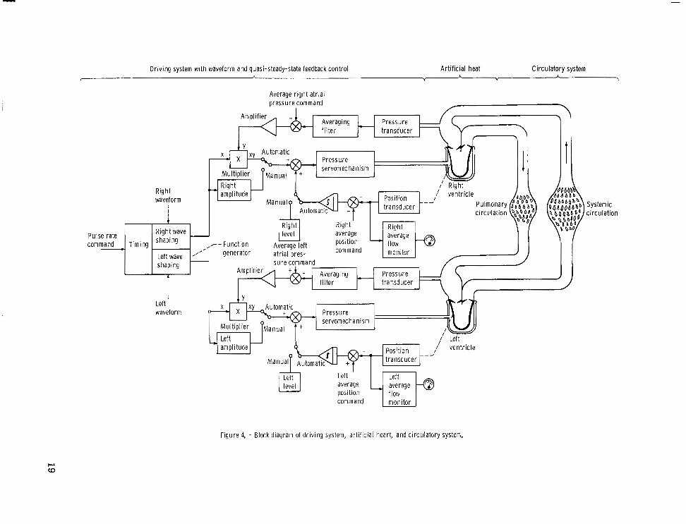
Functionally, the second control system design can be represented by the block dia- gram of figure 4. It consists of a function generator that produces two electrical output voltages and two pressure servomechanisms that convert these voltages to pneumatic pressures for driving the two chambers of an artificial heart. Within the capabilities of the pressure servos they could produce an output pressure proportional to their input voltage. A typical gain factor might be 10 mm Hg (0.13 N/cm ) per volt. Thus a 14- volt input would produce 140 mm Hg (1.9 N/cm ) pressure at the output. The pressure servos employ servovalves specifically designed for this low pressure pneumatic appli- cation.
2 2
Three independent types of manual adjustments (level, amplitude, and waveform) can be made for each channel. The pulse rate adjustment, which is also manual, is common for both channels.
In normal operation the function generator operates in a free run mode at a fixed frequency, for example, 60 beats per minute. This can be adjusted manually to a higher o r lower rate. Desired waveforms of left and right pressure are set up with a matr ix of potentiometers for each waveform. These waveforms can be modified while the function generator is cycling.
An analog computer is used to automatically control the amplitude and level of the pressure waveform when the system is operated in the automatic mode. This computer is used to provide feedback path summing, amplification, intergration, and multiplica- tion as shown in figure 4. The possibility for automatic control of pulse rate is provided by using analog amplifiers apart from the computer (not shown in fig. 4). The only man- ual inputs are the left and right waveform adjustments.
Thus figure 4 represents one way of using the computer controlled driving system. It could be programmed in a short time to be used in several other ways. This system also employs a third redundant pressure servo which can be switched on automatically if needed as a substitute for the left or right channel. This is not shown in the block dia- gram.
Function Generator
It is desired that the function generator provide two output voltages of completely arbitrary waveform with manual adjustment of left and right waveform and automatic or manual adjustment of pulse rate. It is further desired that , as pulse rate is increased, the ratio of the duration of systole to that of diastole would change in a physiological manner, that is, that pulse rate would increase mainly by decreasing diastolic duration.
The entire control system is displayed in figure 5. The function generator can be seen located in the lower portion of the computer console. The function generator is an
8
all electronic unit which provides two completely arbitrary output waveforms as desired but it permits only manual adjustment of pulse rate.
The function generator consists of two diode matrices,, each containing 50 diodes. Thus, there are 50 potentiometers for each channel. A digital ring counter sequentially forward biases the diodes in both matrices so that the voltages set by the potentiometers sequentially appear at the output. Thus the output voltage from each channel is a stair- step function of 50 steps. The steps are of equal length with variable amplitudes. The sweep rate is controlled by an RC timing network which is varied by a n 11 position switch together with a vernier potentiometer. Control of sweep speed by an externally supplied voltage was incorporated by installing an external input voltage jack and a switch for selecting internal or external sweep speed. Further description of the func- tion generator circuitry as delivered can be found in reference 10.
To provide a variable systolic-diastolic duration it was necessary to design a spe- cial purpose timing circuit. The desired variation of systolic and diastolic duration as a function of pulse rate is illustrated in figure 6. At 60 beats per minute a 1 to 2 ratio of systole to diastole is used. At 140 beats per minute a 1 to 1 ratio is used. A t inter- mediate pulse rates the systolic and diastolic durations are changed linearly with pulse rate. Letting most of the increase in pulse rate occur at the expense of diastolic dura- t ionhas a simple hydraulic advantage. The pulse rate can increase with but a small change in peak ejection blood velocity.
To implement the characteristic of figure 6 the first 20 increments were assigned to systole and the last 30 to diastole. This required that the systolic sweep rate, in gen- eral, be different than the diastolic sweep rate. Therefore the control voltage for the first 20 increments had to be different from the control voltage for the next 30 incre- ments. Both control voltages are l inear functions of the pulse rate control voltage as dictated by figure 6.
To accomplish the modification in sweep rate, five small, transistorized analog op- erational amplifiers were rack mounted in the computer console (fig. 5) above the func- tion generator. Three of these were used for the t iming circuit . This is illustrated in figure 7. The rate control voltage was applied at the inputs to amplifiers A2 and A3. A synchronizing signal was received from the function generator when the first 20 incre- ments were being swept. This caused the relay to be energized when the last 30 incre- ments were being swept. By proper adjustment of the three potentiometers the desired linear relationships of systolic and diastolic sweep speed as a function of pulse rate were generated. The other amplifiers in figure 7 were used as first-order lag filters to smooth the stepwise output of the function generator. Thus the individual steps did not appear at the outputs.
9

Servovalve
A survey of off-the-shelf hydraulic and pneumatic servovalves was made to locate a unit which would satisfy the requirements for driving a pneumatic sac-type artificial heart. These requirements are the following:
Driving line length, ft (cm) . . . . . . . . . . . . . . . . . . . . . . . . 6 (1 80) Driving line inside diameter, in. (cm) . . . . . . . . . . . . . . . . . 3/16 (0.48) At valve output:
Pressure amplitude, mm Hg gage (N/cm ). rt250 (3.3) 2 . . . . . . . . . . . . . . . Frequency response, Hz. . . . . . . . . . . . . . . . . . . . . 0 to 30 a t rt3 db
At heart chamber: Pressure amplitude, mm Hg gage (N/cm ) 120 to -50 (1.6 to -0.7) 2 . . . . . . . . . Frequency response, Hz. . . . . . . . . . . . . . . . . . . . 0 to 10 a t 3 db ' i Maximum orifice flow area, in. (cm ) . . . . . . . . . 0.025 to 0.050 (0.16 to 0.32)
The valve should operate equally well with air, C02, and helium at room temperature. Unfortunately, no unit w a s commercially available which could provide operation suited to these requirements. Accordingly, a single-stage low pressure pneumatic servovalve was designed specifically for the artificial heart application.
figuration with a movable metering plate in the center. The metering plate is pivoted about one corner with a leaf spring. It is suspended by air bearings between two sta- tionary plates that are mechanically spaced a fixed distance apart, approximately 0.001 inch (0.002 cm) clearance on either side of the metering plate.
The metering plate is driven by a push rod connected to a commercial electromag- netic torque motor. This torque motor has a maximum force capability of A 3 pounds (rt58 N) at the center position with a maximum armature stroke (at the ends of the arma- ture) of *O. 015 inch (rtO.038 cm). The torque motor produces an output motion in direct proportion to the input e lectr ical current . As seen in sect ion B-B of figure 8, if the me- tering plate is moved to the right by the torque motor, air can pass from the supply pres- sure port to the control pressure port , thereby increasing the pressure to the heart . As the plate is moved to the left, air can pass from the control port to the vacuum port thus decreasing the pressure to the heart .
The resulting servovalve design illustrated in figure 8 is basically a sandwich con-
The use of air bearings to support one end of the metering plate eliminated metal-to- metal contact. Thus, smooth, frictionless operation of the valve was assured.
The servovalve also employs a means for conveniently adjusting the overlap of the valve. This is done by moving the hinge block in relation to the valve body. The valve parts were made of 416 stainless steel. This mater ia l is corrosion resistant, easily machinable, and sufficiently hard for grinding or lapping. The valve parts were
10
stabilized by thermal cycling before being ground to prevent warping over a long period of use. Photographs of the complete assembled and disassembled valve are shown in f igures 9 and 10, respectively.
A plot of steady-state flow as a function of pressure for fixed positions of the valve metering plate is displayed in figure 11. The metering plate positions were measured at the push rod; zero position was taken as the position at which there was zero control flow when the control pressure was zero. Negative positions correspond to the valve metering plate being offset in a direction to open a fixed area orifice between the vacuum supply and the control port.
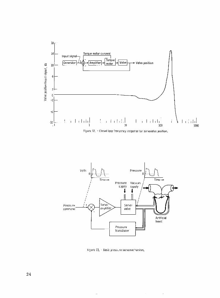
A closed loop frequency response curve of valve position is presented in figure 12. Valve position is normalized to its steady-state value. It w a s measured with a l inear variable differential transformer attached to the torque motor. This signal is fed back to a servoamplifier along with torque motor current feedback as shown in the block dia- gram in figure 12.
The valve response is flat with *2 decibels from 0 hertz to beyond 100 hertz show- ing a resonant peak at about 180 hertz. Table I states that the closed loop pressure con- trol system must operate from 0 to 30 hertz. It appears that the valve position response is adequate; however, the pressure frequency response of the system wi l l depend on the size and length of connecting tubing and size of the artificial heart cavity.
Pressure Servosystem
The pressure servosystem uses the pneumatic servovalve just described in a feed- back control loop as shown in the block diagram in figure 13. The system consists of a high gain servoamplifier, a pneumatic servovalve, and a pressure t ransducer . For simplicity the torque motor current and valve position feedbacks are not shown in this figure. The amplifier compares the input command voltage to the actual pressure out- put of the system by means of a pressure t ransducer . Lf a difference exists, the ampli- fier produces an output current proportional to the difference. The output current from the amplifier drives the servovalve which controls airflow to the heart, thus varying the heart pressure. This negative feedback system will cause the output pressure of the servovalve to track the input command voltage to the servoamplifier. The basic servo- mechanism can then be considered as a single block with an output pressure proportional to its input voltage as indicated in figure 4.
The servoamplifiers are mounted in the servoconsole as shown in figure 5. A pho- tograph of one amplifier module is shown in figure 14. Figure 15 shows the servodrawer removed from its cabinet. This drawer contains the servovalve assembly, the servo- system pressure transducers, and the related pneumatic hardware.
11

Analog Computer
A transistorized, desktop analog computer was included in the driving system to provide the flexibility for a creative research investigation. This computer is seen in figure 5 mounted at the top of the computer console. This computer is used as delivered without modifications. It includes ten operational amplifiers of which four can be used as integrators, two multipliers, and two diode function generators. It is used to pro- vide the automatic adjustments of amplitude, level, and pulse rate (fig. 4) in response to parameters sensed in the heart 's ventricle and atrium. The diode function genera- t o r s are also used to linearize the ventricular volume signals. The computer circuit modules are interconnected with patch cords on the problem board. This permits flex- ibility in closing the feedback loops.
Quasi-Steady-State Control
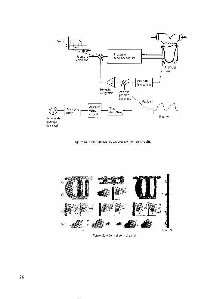
The ventricular blood volume is measured by a transducer which consists of two electrical coils mounted on opposite walls of the blood chamber. One of these coils is excited by a high frequency alternating current. A fixed frequency in the range of 3 to 5 kilohertz is usually satisfactory. Magnetic coupling induces a voltage in the second coil which is proportional to the inverse square of the distance separating the coils. Subsequent demodulation and linearization of this voltage produces a signal proportional to blood volume.
The sac position control circuit is illustrated in figure 16. The blood volume signal is compared to an average position command value. The difference is integrated at a low gain and summed with the pressure command signal. This biases the average level of the pressure waveform, shifting the servovalve's mean output pressure to maintain s a c volume about the commanded set point.
An additional benefit can be derived from sensing blood volume. Electrical differ- entiation, o r an approximation thereof, of the instantaneous blood volume signal yields a signal proportional to instantaneous blood flow into and out of the ventricle. Subsequent averaging of the absolute value of this signal gives a voltage indicative of the average flow in the circulatory system. This voltage is displayed on a panel meter. With the use of two channels it is possible to establish an approximate flow balance between left and right hearts. The average flow rate voltage is also used as an alarm signal. If i t s value drops below an acceptable level the third servochannel is automatically activated.
Figure 4 shows average atrial pressure feedbacks which are used to adjust the am- plitudes of the command voltages supplied to the pressure servos. Analog computer multipliers are used to perform the amplitude adjusting function. The averaging filters
12

in the atrial pressure feedback paths are set to transmit only slowly varying signals to the Y inputs of the multipliers.
These feedbacks can be switched into the circuit at the central control panel of the servoconsole shown in figure 17. This panel also provides the manual controls for pulse rate, left and right amplitude, and left and right level.
RESULTS AND DISCUSSION
The complete system w a s tested with sac hearts in a mock circulatory system filled with water (ref. 11). Atr ia l p ressure was increased by raising the height of the venous return reservoir for the left heart. With the computer controlled driving system pro- grammed in the configuration shown in figure 4 it was possible to determine its respon- s iveness to a t r ia l re turn pressure. In this mode of control, increasing average atrial pressure causes an increased voltage input to the multipliers in series with the function generator output. This increases the amplitude of the pulsatile voltages applied to the pressure servos. The variation of water flow rate with atrial pressure for the lef t hear t is shown in figure 18. The heavy curve shown is the normal curve for the natural left heart. The curves with circles were obtained by adjusting the gain of the amplifier shown in figure 4.
It is noted that, as was reported in reference 5, with a low value of a t r ia l pressure feedback gain the artificial heart is relatively insensitive to atrial pressure. With a feedback gain of 0 .3 the sensitivity of the artificial heart is approximately 0 . 2 5 l i ter per minute per mm Hg(310 cm /(N)(sec)). Increasing the feedback gain to 0 .5 increases the artificial heart 's sensitivity to that of the natural left heart. When the gain is in- creased to 2 . 5, the sensitivity of the artificial heart becomes approximately 4. 5 l i te rs per minute per mm Hg ( 5 . 6 ~ 1 0 cm /(N)(sec)) o r approximately that of the natural r ightheart .
5
3 5
The curves of figure 18 can be translated horizontally by adjusting the average atrial pressure command voltage shown in figure 4. With this adjustment the 0.5 curve could be made to coincide closely with the normal curve for the left ventricle.
The computerized driving system has since been used in a variety of art if ical heart investigations. Results obtained in this work have been reported in the medical litera- ture in references 5 and 12 to 15, A comparison of the computerized driving system to other available driving systems showed that the computerized system is the only system capable of achieving the high sensitivity to atrial pressure required for proper regula- tion of the artificial heart. This sensitivity can be further augmented by the use of in- tegral and integral plus proportional control. Use of this driving system has also been extended to bypass pumping where the bypass pump w a s controlled by atrial pressure to support a failing heart. Such control results in a composite cardiac output curve which
13

is composed of the failing heart's cardiac output curve and the bypass pump's output flow as a function of atrial pressure curve.
In one case a stability problem was encountered where the atrial pressure control oscillated at about 0.26 to 0.05 hertz at low atrial pressures. These oscil lations were attributed to the nonlinear pressure-volume characteristic's of the artificial atrium used for that investigation. This problem could be avoided by compensating for nonlinearities with the control system or by redesigning the artificial atrium. In another case the pressure wave shaping capability of the computerized driving system has been used to study the possibility of paired pulse driving pressures, result ing in increased stroke volume and cardiac output flow from an art if icial heart .
CONCLUDING REMARKS
Based on known physiological information, the pneumatic servosystem described herein was designed and developed to drive an artificial heart in a manner to reproduce the pumping and flow regulating functions of the natural heart .
The system was tested for servovalve frequency response and atrial pressure sen- sitivity. The specially designed servovalve exhibited a position response beyond 100 hertz, which is considered acceptable for reproducing the appropriate pressure wave- forms required at the art if icial heart . The system also was able to produce sufficient atrial pressure sensitivity to duplicate the Starling's law type of curves found in the na- tural heart . Any drift in the average position of the artificial pumping chambers was automatically controlled, thus providing added reliability and repeatability for the pneu- matic sac heart design.
This system has proven to be a useful and versatile research tool by providing many control possibilities through the use of an analog computer. Future work with such a system wi l l help to further define the requirements for totally replacing the heart with a mechanical pump.
Lewis Research Center, National Aeronautics and Space Administration,
Cleveland, Ohio, October 13, 1970, 720-03.
14
REFERENCES
1. Final Summary Report on Six Studies Basic to Consideration of the Artificial Heart Program. HIT-235, NIH Contract PH43-66-90, Hittman Associates, Inc., 1966, pp. 11-1, 11-2, 111-6. (Available from clearinghouse as P B 173483.)
2. Houston, C. S. ; Akutsu, T. ; Kolff, W. J. : Pendulum Type of Artificial Heart Within the Chest: Preliminary Report. American Heart Journal, vol. 59, no. 5, May 1960, pp. 723-730.
3. Guyton, Arthur C. : Circulatory Physiology: Cardiac Output and Its Regulation. W. B. Saunders Co., 1963.
4. Rushmer, Robert F. : Cardiovascular Dynamics. Second Ed. , W. B. Saunders CO. , 1961, pp. 53-72.
5. Nos;, Y. ; Crosby, M. ; Woodward, K. ; Kwann-Gett, C. S.; Hino, K. : and Kolff, W. J. : Respect the Integrity of the Large Veins and Starling's Law. Trans. Am. SOC. Artif. Intern. Organs, vol. 13, 1967, pp. 273-279.
6. Kay, E. B.; Zimmerman, H. A. ; Suzuki, A. (Assisted by Griffin, W. S. ; Gebben, V. D.): Prosthetic Valves: Long Term Results. Ch. 6 in Heart Substitutes, Mechanical and Transplant. Brest, ed. , Charles C. Thomas, 1966.
7. Nos;, Y. ; Kolff, W. J. : The Intracorporeal Mechanical Heart. Vascular Diseases, vol. 3, no. 1, February 1966, pp. 25-32.
8. Woodward, K. E. ; Straub, H. ; Nos&, Y. ; Kolff, W. J. : An Intrathoracic Artifi- cial Heart Controlled by Fluid Amplifiers. Trans. Amer. SOC. Artif. Int. Organs , V O ~ . 12, 1966, pp. 294-300.
9. Hiller, K. W. ; Seidel, W. ; Kolff, W. J. : A Servomechanism to Drive an Artificial Heart Inside the Chest. Trans. Amer. SOC. Artif. Intern. Organs, vol. 8, 1962, pp. 125-130.
10. Instruction Manual Type 200-SN359. Exact Electronics, Inc. , Hillsboro, Oregon, 1962.
11. Kolff, W. J. : Mock Circulation to Test Pumps Designed for Permanent Replace- ment of Damaged Hearts. Cleveland Clinic Quarterly, vol. 26, no. 4, October, 1959, pp. 223-226.
12. Wildevuur, C. R. H. ; Mrava, G. L. ; Crosby, M. J. ; Wright, J. I. ; Hladky, H. L. ; Andreson, G. J.; Pierson, R. M.; Kon, T.; Nos&, Y. : An Artificial Heart Sensitive to Atrial Volume. Trans. Amer. SOC. Artif. Intern. Organs, V O ~ . 14, 1968, pp. 276-282.
1 5

13. Kwan-Gett, C. S o ; Crosby, M. J.; Schoenberg, A.; Jacobsen, S. C.; Kolff, W. J.: Control System for Artificial Hearts. Trans. Amer. SOC. Artif. Intern. Organs, V O ~ , 14, 1968, ppo 284-290,
14. Moulopoulos, S. Do; Crosby, M. J.; Nos;, Y. ; Kolff, W. J. : Paired-Pulse Stim- ulation of an Electro-Hydraulic Pump Used to Replace the Mammalian Heart. Cleveland Clinic Quarterly, vol. 35, Jan, 1968, pp. 41-47.
15. Wildevuur, C. R. H.; Moulopoulos, S. Do ; Kolff, J.; Crosby, M. J.; Nos;, Y. : Supplementary Mechanically Assisted Circulation. The Annals of Thoracic Sur- gery, vol. 6, no. 2, Aug. 1968, pp. 137-145.
16

Pulmonary artery
Upper extremities and head \
Trunk and lower extremities
9 I
Diastole
Valve '\<-Aorta ." Left ventr ic le
0 Time -
-Pulmonaryar te ry """"
Figure 1. -C i rcu la to ry system.

1 f lo Effect of chang ing systemic resistance
I Effect o f chang ing nervous st imulat ion
Cardiac output
Effect of chang ing mean systemic
-2 0 2 4 6 8 Right a t r ia l pressure, mm Hg gage
I I I I -. 04 0 .04 .ox .12
Right atrial pressure, Nlcm'gage
Figure 2. -Typica l card iac output -venous re turn curves for the natural heart .
Pneumatic
x i b l e ventr ic le Inflow valve --
V e i n A r t e r y
' - -Out f low va lve
dr ive l ine yu -R ig id she l l
x i b l e ventr ic le Inflow valve --
V e i n A r t e r y
' - -Out f low va lve
dr ive l ine yu -R ig id she l l
Figure 3. - Sac-type pneumatic artif icial heart.
18
Driv ing system wi th waveform and quasi-steady-state feedback control Art i f ic ial heat Circulatory system <
A V
A \
Pulse rate
I
Average r ight a t r ia l pressure command
I
Averaging Pressure f i l ter transducer
Systemic c i rcu la t ion
Figure 4. - Block diagram of dr iv ing system, art i f ic ia l heart, and circulatory systen;.

Figure 5. - Computer controlled artificial heart driving system.
20

5-
0 -
5 -
D -
- 150-
140 -
130 -
- 120- c .- - E y 110 - n a-
3
z 100- 3
c
- 3 a
- 90 -
80 -
70 -
- 600
Time duration, sec
Figure 6. - Systol ic and diastol ic per iods as funct ions of pulse rate.
Pulse rate con t ro l E , t
-Bias to r i n g c o u n t e r
20 increments, ,730 i nc remen ts I
From $-& waveform- generator +"q + Bias
I I
Bias -
Mat r i x A Matrix: step output Matr ix B step output smoothed
output M s t r i x A smoothed ou tpu t
- Bias - Bias
F igu re 7. - Analog c i rcui ts for funct ion generator modif icat ion.
21

I- Shown with plate displaced to r i g h t 1
Section A-A
Pressure supply J‘ ,/’ ‘LVacuum supply 1 Control pressure
Section B-B
Figure 8. - Pneumatic servovalve configuration.
Figure 9. - Servovalve assembled.
22

$ , , Assembly cover
Man i fo ld ( fo r I(
three valves) Toraue motor ". x6. k.
Meter ing plate--/ H inge b lock ' ' * C-72445
Figure 10. - Disassembled servovalve and mounting manifold.
2x10³ r 4r
Meter ing p late position at
push rod end, in. (cm)
\ 0.020 (0.051)
-4 .:\%\' -
-6 t I I
-A 0 4 8 12 16 20 7
Control pressure
I I -4 0
I d 4 8 12
Control pressure, N / C J gage
Figure 11. - Servovalve steady-state performance. Pressure supply, 30 psig (21 N/cm2 gage); vacuum supply, -12 psig (-8 N/cm2 gage).
P >-
23
18r
14 -
.a = 10 - m c .- “7
3 a - 6 -
c c 0
B “7 2 -
> -2 - m
-6 -
-1O-”l 1 I I I I l l I 1 I I I I I l l I 1 10 100
Figure 12. - Closed loop frequency response for servovalve position.
“I 1 1 1 1 1 1 1 I 1 I 1 1 1 1 1 1 I 1 10 100
Figure 12. - Closed loop frequency response for servovalve position.
Pressure- command
/ Pressure Vacuum ,’ ~
/
/ / I ,,, j“ , ,//, I I /
Art i f ic ia l heart
I 1 I d 1000
Figure 13. - Basic pressure servomechanism,
24

Figure 14. - Servoamplifier module.
C-66-777
Figure 15. - Servcdrawer.
25
Volts 0
servomechanism
I ,J A r t i f i c i a l I hear t
I
Averaging f i l t e r
Panel meter (average flow ratel
Low ga in integrator Average position
value c i r c u i t
derivative Time +
Figure 16. - Position balance and average f low rate circuits.
C-66-771
Figure 17. - Central control panel .
26

m- 12-
10 -
150 - U
3 VI 8- .- c
m i
E,
- d c
5 100- 5
L m c -
- 6- CL 3 3 c
0 " 3 0
a
m U m
c
._ E m 4- 5 0 V
m
50 -
2-
0- 00 I
-2 Left atrial pressure, rnm Hg gage
I 1 I .04 0 .04
I 1 08 .12
Left atr ial pressure, Nlcm' gage
F igu re 18. - Cardiac output curves obtained wi th automat ic ampl i tude and level control .
NASA-Langley, 1911 - 5 E - 5 82 7
I ~~ ~
27

NATIONAL AERONAUTICS AND SPACE ADMINISTRAT ION
WASHINGTON, D. C. 20546
OFFICIAL BUSINESS FIRST CLASS MAIL
NATIONAL AERONAUTICS POSTAGE AND FEES PA1
SPACE ADMINISTRATIOF
05U 0 0 1 30 5 1 3 0 s 71043 00903 A I R FORCE hEAPUNS LABORATORY /WLOL/ K I K T L A N D A F B I NEW V E X I C O 8 7 1 1 7
NASA
. , ..> .
‘ T h e aeronayt>cal and space activities of the United States shall be conducted so as. t o chntribute . . . t o the expansion of haman knowl- edge of ph1??207JIe?aa in the atnlosphere and space. The Administration shall p o v i d e for ‘the widest practicable and appropriate dissemination of information concerning its actiflities and the resalts thereof.”
-NATIONAL AERONAUTICS AND SPACE ACT OF 1958 . . . SCIENTIFIC AND TECHNICAL PUBLICATIONS
. . . . ‘ r .
TECHNICAL REPORTS: Scientific and technical information considkred important, complete, and a lasting concribution to existing knowledge.
TECHNICAL NOTES: Information less broad in scope but nevertheless of importance as a contribution to existing knowledge.
TECHNICAL MEMORANDUMS: Information receiving limited distribution because of preliminary data, security classifica- tion, or other reasons.
TECHNICAL TRANSLATIONS: Information pt~blished in a foreign language considered to merit NASA distribution in English.
SPECIAL PUBLICATIONS: Information derived from or of value to NASA activities. Publications include conference proceedings, monographs, data compilations, handbooks, sourcebooks, and special bibliographies.
TECHNOLOGY UTILIZATION PUBLICATIONS: Information on technology used by NASA that may be of particular
CONTRACTOR REPORTS: Scientific and technical information generated under a NASA Technology Utilization Reports and contract or grant and considered an important contribution to existing knowledge.
interest in commercial and other non-aerospace applications. Publications include Tech Briefs,
Technology Surveys.
Details on the availability of these publications may be obtained from:
SCIENTIFIC AND TECHNICAL INFORMATION OFFICE
NATIONAL AERONAUTICS AND SPACE ADMINISTRATION ’ Washington, D.C. 40546