PN-L702B Operation-Manual GB - Sharp Lietuva · SHARP ELECTRONICS (Europe) ... Keep this manual in...
58
PN-L702B LCD MONITOR OPERATION MANUAL
-
Upload
phamnguyet -
Category
Documents
-
view
225 -
download
0
Transcript of PN-L702B Operation-Manual GB - Sharp Lietuva · SHARP ELECTRONICS (Europe) ... Keep this manual in...

PN-L702BLCD MONITOR
OPERATION MANUAL

IMPORTANT:To aid reporting in case of loss or theft, please record the product’s model and serial numbers in the space provided. The numbers are located in the rear of the product.
Model No.:
Serial No.:
U.S.A. ONLY
FOR CUSTOMERS IN U.K.IMPORTANT
The wires in this mains lead are coloured in accordance with the following code:GREEN-AND-YELLOW: EarthBLUE: NeutralBROWN: Live
As the colours of the wires in the mains lead of this apparatus may not correspond with the coloured markings identifying the terminals in your plug proceed as follows:
•ThewirewhichiscolouredGREEN-AND-YELLOWmustbeconnectedtotheterminalintheplugwhichismarkedbytheletter E or by the safety earth orcolouredgreenorgreen-and-yellow.
•ThewirewhichiscolouredBLUEmustbeconnectedtotheterminalwhichismarkedwiththeletterN or coloured black.•ThewirewhichiscolouredBROWNmustbeconnectedtotheterminalwhichismarkedwiththeletterL or coloured red.
Ensurethatyourequipmentisconnectedcorrectly.Ifyouareinanydoubtconsultaqualifiedelectrician.“WARNING: THIS APPARATUS MUST BE EARTHED.”
AuthorisedrepresentativeresponsiblefortheEuropeanUnionCommunityMarket
SHARPELECTRONICS(Europe)GmbHSonninstraße3,D-20097Hamburg

3 E
IMPORTANT INFORMATION
WARNING: TOREDUCETHERISKOFFIREORELECTRICSHOCK,DONOTEXPOSETHISPRODUCTTORAINORMOISTURE.
RISKOFELECTRICSHOCKDONOTOPEN
CAUTION
CAUTION: TOREDUCETHERISKOFELECTRICSHOCK,DONOTREMOVECOVER. NOUSER-SERVICEABLEPARTSINSIDE. REFERSERVICINGTOQUALIFIEDSERVICEPERSONNEL.
Thelightningflashwitharrowheadsymbol,withinanequilateraltriangle,isintendedtoalerttheuser to the presence of uninsulated “dangerous voltage” within the product’s enclosure that may beofsufficientmagnitudetoconstituteariskofelectric shock to persons.
The exclamation point within a triangle is intended to alert the user to the presence of importantoperatingandmaintenance(servicing)instructions in the literature accompanying the product.
WARNING: FCCRegulationsstatethatanyunauthorizedchangesormodificationstothisequipmentnotexpresslyapprovedbythemanufacturercouldvoidtheuser’sauthoritytooperatethisequipment.
NOTE:ThisequipmenthasbeentestedandfoundtocomplywiththelimitsforClassAdigitaldevice,pursuanttoPart15oftheFCCRules.Theselimitsaredesignedtoprovidereasonableprotectionagainstharmfulinterferencewhentheequipmentisoperatedinacommercialenvironment.Thisequipmentgenerates,uses,andcanradiateradiofrequencyenergyand,ifnot installed and used in accordance with the instruction manual, may cause harmful interference to radio communications. Operationofthisequipmentinaresidentialareaislikelytocauseharmfulinterferenceinwhichcasetheuserwillberequiredto correct the interference at his own expense.
ThisproductutilizesaCRcoinLithiumbatterywhichcontainsaPerchloratematerial.Special handling for this material may apply,Californiaresidents,Seewww.dtsc.ca.gov/hazardouswaste/perchlorate/Others,consultlocalenvironmentalofficers.
U.S.A. ONLY

4E
IMPORTANT INFORMATION (Continued)
A. Information on Disposal for Users (private households)1. In the European UnionAttention:Ifyouwanttodisposeofthisequipment,pleasedonotusetheordinarydustbin!
Usedelectricalandelectronicequipmentmustbetreatedseparatelyandinaccordancewithlegislationthatrequirespropertreatment,recoveryandrecyclingofusedelectricalandelectronicequipment.Followingtheimplementationbymemberstates,privatehouseholdswithintheEUstatesmayreturntheirusedelectricalandelectronicequipmenttodesignatedcollectionfacilitiesfreeofcharge*.Insomecountries*yourlocalretailermayalsotakeback your old product free of charge if you purchase a similar new one.
*)Pleasecontactyourlocalauthorityforfurtherdetails.
Ifyourusedelectricalorelectronicequipmenthasbatteriesoraccumulators,pleasedisposeoftheseseparatelybeforehandaccordingtolocalrequirements.
Bydisposingofthisproductcorrectlyyouwillhelpensurethatthewasteundergoesthenecessarytreatment,recoveryandrecycling and thus prevent potential negative effects on the environment and human health which could otherwise arise due to inappropriate waste handling.
2. In other Countries outside the EUIf you wish to discard this product, please contact your local authorities and ask for the correct method of disposal.
ForSwitzerland:Usedelectricalorelectronicequipmentcanbereturnedfreeofchargetothedealer,evenifyoudon’tpurchaseanewproduct.Furthercollectionfacilitiesarelistedonthehomepageofwww.swico.chorwww.sens.ch.
B. Information on Disposal for Business Users1. In the European UnionIf the product is used for business purposes and you want to discard it:
PleasecontactyourSHARPdealerwhowillinformyouaboutthetake-backoftheproduct.Youmightbechargedforthecostsarisingfromtake-backandrecycling.Smallproducts(andsmallamounts)mightbetakenbackbyyourlocalcollectionfacilities.
ForSpain:Pleasecontacttheestablishedcollectionsystemoryourlocalauthorityfortake-backofyourusedproducts.
2. In other Countries outside the EUIf you wish to discard of this product, please contact your local authorities and ask for the correct method of disposal.
Attention: Your product is marked with this symbol. It means that used electrical and electronic products should not be mixed with general household waste. There is a separate collection system for these products.
The battery supplied with this product contains traces of Lead.ForEU:Thecrossed-outwheeledbinimpliesthatusedbatteriesshouldnotbeputtothegeneralhouseholdwaste!Thereisaseparatecollectionsystemforusedbatteries,toallowpropertreatmentandrecyclinginaccordance with legislation. Please contact your local authority for details on the collection and recycling schemes.
ForSwitzerland:The used battery is to be returned to the selling point.
Forothernon-EUcountries:Please contact your local authority for correct method of disposal of the used battery.
“BATTERYDISPOSAL”THISPRODUCTCONTAINSALITHIUMPRIMARY(MANGANESSDIOXIDE)MEMORYBACK-UPBATTERYTHATMUSTBEDISPOSEDOFPROPERLY.PLEASECONTACTYOURLOCALSHARPDEALERORAUTHORIZEDSERVICEREPRESENTATIVEFORASSISTANCEINDISPOSINGOFTHISBATTERY.
U.S.A.ANDCANADAONLY
EUONLY
EUONLY
5 E
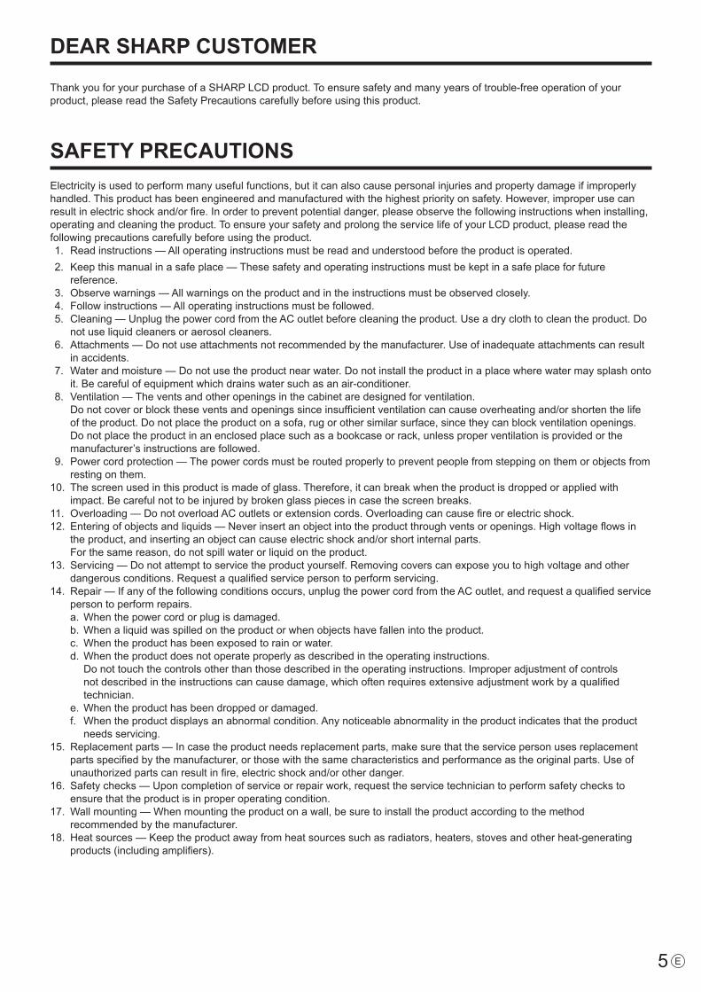
ThankyouforyourpurchaseofaSHARPLCDproduct.Toensuresafetyandmanyyearsoftrouble-freeoperationofyourproduct, please read the Safety Precautions carefully before using this product.
SAFETY PRECAUTIONSElectricityisusedtoperformmanyusefulfunctions,butitcanalsocausepersonalinjuriesandpropertydamageifimproperlyhandled. This product has been engineered and manufactured with the highest priority on safety. However, improper use can resultinelectricshockand/orfire.Inordertopreventpotentialdanger,pleaseobservethefollowinginstructionswheninstalling,operatingandcleaningtheproduct.ToensureyoursafetyandprolongtheservicelifeofyourLCDproduct,pleasereadthefollowing precautions carefully before using the product. 1. Readinstructions—Alloperatinginstructionsmustbereadandunderstoodbeforetheproductisoperated. 2. Keepthismanualinasafeplace—Thesesafetyandoperatinginstructionsmustbekeptinasafeplaceforfuture
reference. 3. Observewarnings—Allwarningsontheproductandintheinstructionsmustbeobservedclosely. 4. Followinstructions—Alloperatinginstructionsmustbefollowed. 5. Cleaning—UnplugthepowercordfromtheACoutletbeforecleaningtheproduct.Useadryclothtocleantheproduct.Do
notuseliquidcleanersoraerosolcleaners. 6. Attachments—Donotuseattachmentsnotrecommendedbythemanufacturer.Useofinadequateattachmentscanresult
in accidents. 7. Waterandmoisture—Donotusetheproductnearwater.Donotinstalltheproductinaplacewherewatermaysplashonto
it.Becarefulofequipmentwhichdrainswatersuchasanair-conditioner. 8. Ventilation—Theventsandotheropeningsinthecabinetaredesignedforventilation. Donotcoverorblocktheseventsandopeningssinceinsufficientventilationcancauseoverheatingand/orshortenthelife
oftheproduct.Donotplacetheproductonasofa,rugorothersimilarsurface,sincetheycanblockventilationopenings.Donotplacetheproductinanenclosedplacesuchasabookcaseorrack,unlessproperventilationisprovidedorthemanufacturer’s instructions are followed.
9. Powercordprotection—Thepowercordsmustberoutedproperlytopreventpeoplefromsteppingonthemorobjectsfromresting on them.
10. Thescreenusedinthisproductismadeofglass.Therefore,itcanbreakwhentheproductisdroppedorappliedwithimpact.Becarefulnottobeinjuredbybrokenglasspiecesincasethescreenbreaks.
11. Overloading—DonotoverloadACoutletsorextensioncords.Overloadingcancausefireorelectricshock.12. Enteringofobjectsandliquids—Neverinsertanobjectintotheproductthroughventsoropenings.Highvoltageflowsin
theproduct,andinsertinganobjectcancauseelectricshockand/orshortinternalparts. Forthesamereason,donotspillwaterorliquidontheproduct.13. Servicing—Donotattempttoservicetheproductyourself.Removingcoverscanexposeyoutohighvoltageandother
dangerousconditions.Requestaqualifiedservicepersontoperformservicing.14. Repair—Ifanyofthefollowingconditionsoccurs,unplugthepowercordfromtheACoutlet,andrequestaqualifiedservice
person to perform repairs. a.Whenthepowercordorplugisdamaged. b.Whenaliquidwasspilledontheproductorwhenobjectshavefallenintotheproduct. c. Whentheproducthasbeenexposedtorainorwater. d.Whentheproductdoesnotoperateproperlyasdescribedintheoperatinginstructions. Donottouchthecontrolsotherthanthosedescribedintheoperatinginstructions.Improperadjustmentofcontrols
notdescribedintheinstructionscancausedamage,whichoftenrequiresextensiveadjustmentworkbyaqualifiedtechnician.
e.Whentheproducthasbeendroppedordamaged. f. Whentheproductdisplaysanabnormalcondition.Anynoticeableabnormalityintheproductindicatesthattheproduct
needs servicing.15. Replacementparts—Incasetheproductneedsreplacementparts,makesurethattheservicepersonusesreplacement
partsspecifiedbythemanufacturer,orthosewiththesamecharacteristicsandperformanceastheoriginalparts.Useofunauthorizedpartscanresultinfire,electricshockand/orotherdanger.
16. Safetychecks—Uponcompletionofserviceorrepairwork,requesttheservicetechniciantoperformsafetycheckstoensure that the product is in proper operating condition.
17. Wallmounting—Whenmountingtheproductonawall,besuretoinstalltheproductaccordingtothemethodrecommended by the manufacturer.
18. Heatsources—Keeptheproductawayfromheatsourcessuchasradiators,heaters,stovesandotherheat-generatingproducts(includingamplifiers).
DEAR SHARP CUSTOMER

6E
SAFETY PRECAUTIONS (Continued)
19. Batteries—Incorrectuseofbatteriesmaycausethebatteriestoburstorignite.Aleakybatterymaycorrodetheequipment,dirty your hands or spoil your clothing. In order to avoid these problems, make sure to observe the precautions below:
•Usethespecifiedbatteriesonly. •Installthebatterieswithdueattentiontotheplus(+)andminus(-)sidesofthebatteriesaccordingtotheinstructionsinthe
compartment. •Donotmixoldandnewbatteries. •Donotmixbatteriesofdifferenttypes.Voltagespecificationsofbatteriesofthesameshapemayvary. •Replaceanexhaustedbatterywithanewonepromptly. •Ifyouwillnotusetheremotecontrolforalongtime,removethebatteries. •Ifleakedbatteryfluidgetsonyourskinorclothing,rinseimmediatelyandthoroughly.Ifitgetsintoyoureye,batheyour
eyewellratherthanrubbingandseekmedicaltreatmentimmediately.Leakedbatteryfluidthatgetsintoyoureyeoryourclothing may cause a skin irritation or damage your eye.
20. Usageofthemonitormustnotbeaccompaniedbyfatalrisksordangersthat,couldleaddirectlytodeath,personalinjury,severe physical damage or other loss, including nuclear reaction control in nuclear facility, medical life support system, and missile launch control in a weapon system.
21. Donotstayincontactwiththepartsoftheproductthatbecomehotforlongperiodsoftime.Doingsomayresultin low-temperatureburns.
WARNING:This is a class A product. In a domestic environment this product may cause radio interference in which case the user may be requiredtotakeadequatecountermeasures.
TomaintaincompliancewithEMCregulations,useshieldedcablestoconnecttothefollowingterminals:PC/AVDVI-Doutputterminal,PC/AVDVI-Dinputterminal,PC/AVHDMIinputterminal,PCD-SUBinputterminal,PCRGBinputterminals,andRS-232Cinput/outputterminals.
Ifamonitorisnotpositionedinasufficientlystablelocation,itcanbepotentiallyhazardousduetofalling.Manyinjuries,particularly to children, can be avoided by taking simple precautions such as:•Usingfixingdeviceslikewallmountbracketsrecommendedbythemanufacturer.•Onlyusingfurniturethatcansafelysupportthemonitor.•Ensuringthemonitorisnotoverhangingtheedgeofthesupportingfurniture.•Notplacingthemonitorontallfurniture(forexample,cupboardsorbookcases)withoutanchoringboththefurnitureandthe
monitor to a suitable support.•Notstandingthemonitorsonclothorothermaterialsplacedbetweenthemonitorandsupportingfurniture.•Educatingchildrenaboutthedangersofclimbingonfurnituretoreachthemonitororitscontrols.
Especially for child safety-Don’tallowchildrentoclimbonorplaywiththemonitor.-Don’tplacethemonitoronfurniturethatcaneasilybeusedassteps,suchasachestofdrawers.-Rememberthatchildrencanbecomeexcitedwhilewatchingaprogram,especiallyona“largerthanlife”monitor.Care
should be taken to place or install the monitor where it cannot be pushed, pulled over, or knocked down.-Careshouldbetakentorouteallcordsandcablesconnectedtothemonitorsothattheycannotbepulledorgrabbedby
curious children.

7 E
-TheTFTcolorLCDpanelusedinthismonitorismadewiththe application of high precision technology. However, there may be minute points on the screen where pixels never light or are permanently lit. Also, if the screen is viewed from an acute angle there may be uneven colors or brightness. Please note that these are not malfunctions but common phenomenaofLCDsandwillnotaffecttheperformanceofthe monitor.
-Donotdisplayastillpictureforalongperiod,asthiscouldcause a residual image.
-Neverrubortapthemonitorwithhardobjects.-PleaseunderstandthatSHARPCORPORATIONbearsno
responsibility for errors made during use by the customer or a third party, nor for any other malfunctions or damage to this product arising during use, except where indemnity liability is recognizedunderlaw.
-Thismonitoranditsaccessoriesmaybeupgradedwithoutadvance notice.
-Donotusethemonitorwherethereisalotofdust,wherehumidity is high, or where the monitor may come into contact withoilorsteam,asthiscouldleadtofire.
-Ensurethatthemonitordoesnotcomeintocontactwithwaterorotherfluids.Ensurethatnoobjectssuchaspaperclipsorpinsenterthemonitorasthiscouldleadtofireorelectric shock.
-Donotplacethemonitorontopofunstableobjectsorinunsafeplaces.Donotallowthemonitortoreceivestrongshocksortostronglyvibrate.Causingthemonitortofallortopple over may damage it.
-Donotusethemonitornearheatingequipmentorinplaceswhere there is likelihood of high temperature, as this may leadtogenerationofexcessiveheatandoutbreakoffire.
-Donotusethemonitorinplaceswhereitmaybeexposedtodirect sunlight.
-TheACoutletshallbeinstalledneartheequipmentandshallbe easily accessible.
-DonottouchthescreenwhilethePCisstartingup,sinceit will be detected as a failure of the infrared transmitter/receiverelementsandwillleadtoamalfunction.Whenthisoccurs,restartthePC.
-Donotoperatethescreenwithahardorpointedobjectsuchasafingernail,pen,orpencil.
-Twotouchpanelscannotbeusedwhentwodisplaysareconnected to the computer. Only the touch panel on the display that is set as the primary monitor will be operable.
-IfanotherUSBdeviceisconnectedtothecomputertowhichthetouchpanelisconnected,donotoperatetheUSBdeviceduring touch panel input. Input may not take place correctly.
-Iftwotouchpanelsareusedincloseproximitytoeachother,use handwriting mode. The touch pens will interfere with each other and will not operate correctly.
-Iftheinfraredtransmitter/receiverbecomesdirty,malfunctioning may result. Use a soft cloth to gently wipe dirt off the infrared transmitter/receiver.
-Ifdustaccumulatesinsidetheinfraredtransmitter/receiver,the product cannot transmit or receive infrared rays properly, resulting in a malfunction. To clean the dust accumulated inside,contactanauthorizedSHARPservicingdealerorservicecenter(extrachargerequired).
The Power Cord-Useonlythepowercordsuppliedwiththemonitor.-Donotdamagethepowercordnorplaceheavyobjectson
it, stretch it or over bend it. Also, do not add extension cords. Damagetothecordmayresultinfireorelectricshock.
-Donotusethepowercordwithapowertap. Addinganextensioncordmayleadtofireasaresultofoverheating.
-Donotremoveorinsertthepowerplugwithwethands.Doingsocouldresultinelectricshock.
-Unplugthepowercordifitisnotusedforalongtime.-Donotattempttorepairthepowercordifitisbroken
or malfunctioning. Refer the servicing to the service representative.
Manual Scope-Microsoft,Windows,WindowsVistaandInternetExplorerareregisteredtrademarksofMicrosoftCorporation.
-HDMI,theHDMILogoandHigh-DefinitionMultimediaInterfacearetrademarksorregisteredtrademarksofHDMILicensingLLC.
-Adobe,Acrobat,andReaderareeitherregisteredtrademarksor trademarks of Adobe Systems Incorporated in the United States and/or other countries.-Intel,Celeron,andIntelCore2DuoaretrademarksorregisteredtrademarksofIntelCorporationoritssubsidiariesin the U.S.A. and other countries.
-AMD,AMDSempron,AMDAthlon,andcombinationsthereofaretrademarksofAdvancedMicroDevices,Inc.-ThisproductcomeswithRICOHBitmapFontsproducedandsoldbyRICOHCOMPANY,LTD.
-Allotherbrandandproductnamesaretrademarksorregistered trademarks of their respective holders.-LanguageofOSDmenuusedinthismanualisEnglishby
way of example.-Illustrationsinthismanualmaynotexactlyrepresentthe
actual product or display.
LED Backlight● TheLEDbacklightinthisproducthasalimitedlifetime. *Ifthescreengetsdarkordoesnotturnon,itmaybe
necessarytoreplacetheLEDbacklight.ThisLEDbacklight is exclusive to this product and must be replaced byanauthorizedSHARPservicingdealerorservicecenter.
*PleasecontactyourlocalSHARPservicingdealerorservice center for assistance.
TIPS AND SAFETY INSTRUCTIONS

8E
MOUNTING PRECAUTIONS
• Thisproductisforuseindoors.• AmountingbracketcompliantwithVESAspecificationsis
required.• Sincethemonitorisheavy,consultyourdealerbefore
installing, removing or moving the monitor.• Mountingthemonitoronthewallrequiresspecialexpertise
andtheworkmustbeperformedbyanauthorizedSHARPdealer. You should never attempt to perform any of this work yourself. Our company will bear no responsibility foraccidentsorinjuriescausedbyimpropermountingormishandling.
• Thismonitorcannotbeusedinverticalorientation.• Usethemonitorwiththesurfaceperpendiculartoalevel
surface.Ifnecessary,themonitormaybetiltedupto20degrees upward.
• Whenmovingthemonitor,besuretoholditwitheitherbothhandlesorthe4cornersonthebottomoftheunit.Donotplace your hand on the screen. This may cause product damage,failure,orinjury.
• Thismonitorshouldbeusedatanambienttemperaturebetween41°F(5°C)and95°F(35°C).Provideenoughspace around the monitor to prevent heat from accumulating inside.
7-7/8 [20]Unit: inch [cm]
2 [5]
2[5]
2[5]
1-7/16 [3.5]
• Ifitisdifficulttoprovidesufficientspaceforanyreasonsuch as the installation of the monitor inside a housing, or if the ambient temperature may be outside of the range of41°F(5°C)to95°F(35°C),installafanortakeothermeasures to keep the ambient temperature within the requiredrange.
• TemperatureconditionmaychangewhenusingthemonitortogetherwiththeoptionalequipmentsrecommendedbySHARP. In such cases, please check the temperature conditionspecifiedbytheoptionalequipments.
• Donotblockanyventilationopenings.Ifthetemperatureinside the monitor rises, this could lead to a malfunction.
• Donotplacethemonitoronadevicewhichgeneratesheat.• Donotusetheproductinlocationswheretheunitis
exposed to direct sunlight or other strong light. Since this product operates with infrared rays, such light may cause a malfunction.

9 E
Forinformationonthetouchpaneldriver,seetheTouchPanelDriverOperationManual.ForinformationonthePenSoftware,see the Pen Software Operation Manual.
Supplied ComponentsIf any component should be missing, please contact your dealer. LiquidCrystalDisplayMonitor:1 Remotecontrolunit:1 Cableclamp:2 Powercord:1 R-6battery(“AA”size):2 CD-ROM(UtilityDiskforWindows):1 SetupManual:1 Touchpen:1* SharpCorporationholdsauthorshiprightstotheUtilityDiskprogram.Donotreproduceitwithoutpermission.* Forenvironmentalprotection! Donotdisposeofbatteriesinhouseholdwaste.Followthedisposalinstructionsforyourarea.
Pentip(fortouchpen):2 Touch pen battery (LR-03(“AAA”size)):1
USBcable:1 Eraser:1 Tray:1 Traymountingfitting (cover/bracket):x2
System RequirementsTo use the touch panel, the touch panel must be connected to a computer, and the touch panel driver and Pen Software must be installedonthecomputerfromthesuppliedCD-ROM.Systemrequirementsforeachsoftwareprogramareasfollows.
Computer PC/ATcompatiblecomputerwithaUSB1.1port(mustbeabletosupplya500mA(5.0V)current)andabletooutputaresolutionof1920x1080.(CD-ROMdriverequiredforsoftwareinstallation.)
OS WindowsXP(32-bitor64-bitversion),WindowsVista(32-bitor64-bitversion),Windows7(32-bitor64-bitversion)
CPU IntelCeleronorAMDSempron1.6GHzorfasterIntelCore2DuoorAMDAthlonIIX22.8GHzorfasterrecommended
Memory Atleast2GB(atleast1GBforWindowsXP)Freespaceonharddrive Atleast100MB(freespaceseparatelyrequiredfordatastorage)
Toconnectthetouchpanelandinstallthetouchpaneldriver,seetheTouchPanelDriverOperationManual.To install the Pen Software, see the Pen Software Operation Manual.
ContentsIMPORTANT INFORMATION ............................................3DEAR SHARP CUSTOMER ..............................................5SAFETY PRECAUTIONS ..................................................5TIPS AND SAFETY INSTRUCTIONS ...............................7MOUNTING PRECAUTIONS ............................................8Supplied Components .....................................................9System Requirements .....................................................9Part Names .....................................................................10Connecting Peripheral Equipment ...............................12
ConnectionwithaPCorAVequipment .....................12ConnectionwhenthePN-ZB01(optional) is attached .................................................................13
Connecting the Power Cord .........................................14Binding Cables ...............................................................14Removing the Handles ..................................................14Preparing the Remote Control Unit ..............................15
Installing the batteries ................................................15Remote control operation range .................................15
Turning Power On/Off ....................................................16Turning on the main power.........................................16Turning power on/off ..................................................16Disablingpoweron/offoperations ..............................17
Touch Pen Preparations/Touch Action ........................18Inserting the battery ...................................................18Touch action and touch mode ....................................18
Touch action ...............................................................18Other functions ...........................................................20Cautionarypoints .......................................................20Eraser .........................................................................20
Basic Operation .............................................................21Menu Items .....................................................................23
Displayingthemenuscreen .......................................23Menu item details .......................................................24AdjustmentsforPCscreendisplay ............................30
Initialization (Reset)/Functional Restriction Setting (FUNCTION) ....................................................................31Controlling the Monitor with a PC (RS-232C) ..............32
PCconnection ............................................................32Communicationconditions .........................................32Communicationprocedure .........................................32SettingoftheGAMMAuserdata ................................35RS-232Ccommandtable ...........................................36
Controlling the Monitor with a PC (LAN) .....................43Settings to connect to a LAN ......................................43ControllingwithaPC ..................................................45
Troubleshooting .............................................................51Specifications ...............................................................53Mounting Precautions (For SHARP dealers and service engineers) ...............57
Traymountingscrews:M5x4/M4x2 Terminallabel:1
Used when installing the interface expansionboardPN-ZB01(optional).
CoverSharplogo:1 Place this sticker onto the SHARP logo to cover the logo.

10E
nFront view
76 8
1 1
5
2 2
2
2
4 3
1. Touch pen ultrasonic sensor 2. Infrared transmitter/receiver 3. Power button (Seepage16.) 4. Tray 5. Touch panel power LED 6. Remote control sensor (Seepage15.) 7. Input switch (Seepage21.) 8. Power LED (Seepage16.)
Part Names
nRear view
1817
16
19
222120
2423
2
1
4
1514
5
6
789101112
3
When the PN-ZB01(optional) is attached
25
13
1. Optional attachment sectionThis section is used to connect optional hardware for function expansion. Offering this attachment location is not a guarantee that future compatible hardware attachments will be released.
2. Speakers 3. Handles (Seepage14.) 4. Vents 5. Expansion terminal cover
Additional input/output terminals are availablebyattachingthePN-ZB01interfaceexpansionboard(optional).
6. PC/AV HDMI input terminal (Seepage12.)
7. PC D-sub input terminal (Seepage12.)
8. Audio input terminal (Seepage12.) 9. Audio output terminals (Seepage12.) 10. RS-232C output terminal (Seepage
12.) 11. RS-232C input terminal (Seepage12.) 12. Optional terminal
This terminal is provided for possible future(optional)functionexpansion.Offering of this terminal is not a guarantee that future expanded functionality will be provided.
13. USB port 14. AC input terminal (Seepage14.) 15. Main power switch (Seepage16.)Caution
• ConsultyourSHARPdealerforattachment/detachmentofoptional parts.
• Donotopentheexpansionterminalcoverbyyourself. There are high voltage parts inside the cover which may cause an electric shock.
When the PN-ZB01 (optional) is attached 16. PC/AV DVI-D input terminal (Seepage13.) 17. PC/AV DVI-D output terminal (Seepage13.) 18. LAN terminal (Seepage13.) 19. External speaker terminals (Seepage13.) 20. Audio 1 input terminals (Seepage13.) 21. Audio 2 input terminals (Seepage13.) 22. PC RGB input terminals (Seepage13.) 23. AV component input terminals (Seepage13.) 24. AV video input terminal (Seepage13.) 25. AV S-video input terminal (Seepage13.)

11 E
Part Names
nRemote control unit1
2
3
4
5
6
9
8
7
1. Signal transmitter 2. POWER button(Seepage16.) 3. MUTE button(Seepage21.) 4. VOL +/- buttons(Seepage21.) BRIGHT +/- buttons(Seepage21.) Cursor control ( / / / ) buttons 5. DISPLAY button(Seepage21.) 6. MODE button(Seepage21.) 7. INPUT button(Seepage21.) 8. MENU button(Seepage21.) 9. SIZE button(Seepage21.)

12E
Connecting Peripheral Equipment
Caution
• Besuretoturnoffthemainpowerswitchanddisconnectthe plug from the power outlet before connecting/disconnecting cables. Also, read the manual of the equipmenttobeconnected.
• Becarefulnottoconfusetheinputterminalwiththeoutputterminal when connecting cables. Accidentally reversing cables connected to the input and output terminals may cause malfunctions and the other problems.
TIPS
• Whenusingthetouchpanel,connecttheUSBcabletothecomputer.Fordetails,seetheTouchPanelDriverOperation Manual.
• Imagesmaynotbedisplayedproperlydependingonthecomputer(videocard)tobeconnected.
• Ascreenwith1920x1080resolutionmaynotbedisplayedcorrectlyonPCRGB.Inthiscase,checkthesettingsofyourcomputer(videocard)toverifythatinputsignalsconformtospecificationsofthismonitor.(Seepage55.)
• IfthereisacheckboxtodisableEDIDindisplaycontrolpanel,checkitwhenusingPCRGB.
• UsetheautomaticscreenadjustmentwhenaPCscreenisdisplayedforthefirsttimeusingPCD-SUBorPCRGB,orwhenthesettingofthePCischanged.ThescreenisadjustedautomaticallywhenSELFADJUSTintheOPTIONmenu is set to ON.
• Iftheaudiooutputfromtheplaybackdeviceisconnecteddirectly to speakers or other devices, the video on the monitor may appear delayed from the audio portion. Audio should be played through this monitor by connecting the playback device to the monitor’s audio input, and connecting the monitor’s audio output to the speakers or other devices.
• Theaudioinputterminalsusedineachinputmodearefactory-setasfollows.
Input mode Audio input terminal(Factory setting)
PCD-SUB,PCDVI-D,PCRGB Audio input terminalAVDVI-D Audio1inputterminalAVCOMPONENT(BNC),AVS-VIDEO,AVVIDEO(BNC) Audio2inputterminal
AVCOMPONENT(D-SUB),AVVIDEO(D-SUB) Audio input terminal
PCHDMI,AVHDMI PC/AVHDMIinputterminal
Connection with a PC or AV equipment 1. PC/AV HDMI input terminal• UseacommerciallyavailableHDMIcable(conformingto
theHDMIstandard).• SetHDMIofINPUTSELECTontheOPTIONmenu
according to the device to be connected.• SelecttheaudioinputterminaltobeusedinPCHDMI
orAVHDMIofAUDIOSELECTontheOPTIONmenu.WhenHDMIisselected,connectiontotheaudioinputterminal is unnecessary.
2. PC D-sub input terminal• SetD-SUBofINPUTSELECTontheOPTIONmenu
according to the device to be connected.• CommonterminalforAVCOMPONENTandAVVIDEO.• WhenthePN-ZB01(optional)isattached,selecttheaudio
inputterminaltobeusedinPCD-SUBofAUDIOSELECTon the OPTION menu.
• TousewithAVVIDEO(D-SUB),connectthegreenterminal to the device’s video output.
3. Audio input terminal• Useanaudiocablewithoutresistance.• WhenthePN-ZB01(optional)isattached,settheaudio
inputterminalusedforeachinputmodeinAUDIOSELECTontheOPTIONmenu.
4. Audio output terminals• Theoutputsoundvariesdependingontheinputmode.• Thevolumeoftheoutputsoundcanbefixedbysetting
AUDIOOUTPUT(RCA)ontheOPTIONmenu.• Itisnotpossibletocontrolthesoundoutputfromthe
audiooutputterminalswiththeAUDIOmenu.
5. RS-232C input terminal RS-232C output terminal
• YoucancontrolthemonitorfromaPCbyconnectingacommerciallyavailableRS-232straightcablebetweentheseterminalsandthePC.
6. USB port• Tousethetouchpanel,connectthetouchpaneltoyour
computerwiththeprovidedUSBcable.(TouchPanelDriverOperationManual.)
1315
7
14
8
12
109
1
23455
When the PN-ZB01 (optional) is attached
11
6

13 E
Connecting Peripheral Equipment
Connection when the PN-ZB01 (optional) is attachedThePN-ZB01expansionboard(optional)allowstheuseofadditional connection terminals.
7. PC/AV DVI-D input terminal• SetDVIofINPUTSELECTontheOPTIONmenu
according to the device to be connected.• SelecttheaudioinputterminaltobeusedinPCDVI-Dor
AVDVI-DofAUDIOSELECTontheOPTIONmenu.
8. PC RGB input terminals• SetBNCofINPUTSELECTontheOPTIONmenutoPC
RGBwhenusingthePCRGBinputterminals.• SelecttheaudioinputterminaltobeusedinPCRGBof
AUDIOSELECTontheOPTIONmenu.
9. AV component input terminals• SetBNCofINPUTSELECTontheOPTIONmenuto
AVCOMPONENTwhenusingtheAVcomponentinputterminals.
• SelecttheaudioinputterminaltobeusedinAVCOMPONENTofAUDIOSELECTontheOPTIONmenu.
• CannotbeusedwhenD-SUBinINPUTSELECTontheOPTIONmenuissettoAVCOMPONENT.
10. AV video input terminal• SelecttheaudioinputterminaltobeusedinAVVIDEOof
AUDIOSELECTontheOPTIONmenu.• CannotbeusedwhenD-SUBinINPUTSELECTonthe
OPTIONmenuissettoAVVIDEO.
11. AV S-video input terminal• SelecttheaudioinputterminaltobeusedinAVS-VIDEO
ofAUDIOSELECTontheOPTIONmenu.
12. Audio1 input terminals / Audio2 input terminals• Settheaudioinputterminaltobeusedineachinput
modeinAUDIOSELECTontheOPTIONmenu.
13. LAN terminal• YoucancontrolthemonitorfromaPConanetworkby
connecting a commercially available LAN cable between this terminal and a network.
14. External speaker terminals• Touseexternalspeakers,setSPEAKERSELECTonthe
SETUPmenutoEXTERNAL.• Besuretouseexternalspeakerswithanimpedanceof6Ω
orgreaterandaratedinputofatleast7W.
1 32Approx.3-15/16 inch(10 cm)
1.Attachaspeakercablecore(includedwiththePN-ZB01)tothe end of the speaker cable connected to the monitor.
2.Whilepushingthetab,insertthetipofthecable.3. Release the tab.
TIPS
• Besuretoconnectthe+and-terminalsandtheleftandright speakers properly.
• Avoidshortcircuitingthe+and-terminals.• WhenSPEAKERSELECTissettoEXTERNAL,the
internal speakers are disabled.
15. PC/AV DVI-D output terminal• ThevideoofthePC/AVDVI-Dinputcanbeoutputtoan
external device.• OutputtingHDCP-encryptedvideorequiresanexternal
devicewhichsupportsHDCP.• Thisterminalallowsthedaisychainconnectionofupto5
monitors.
TIPS
• Thelengthofthesignalcablesorsurroundingenvironmentmayaffecttheimagequality.
• ThescreenmaynotdisplayproperlywhenusingterminalsotherthanPCDVI-D/AVDVI-Dfortheinputmode.Inthiscase, turn off the power to all the monitors connected in a daisy chain and then turn the power on again.
• WhenconnectingmonitorsinadaisychainsetAUTOINPUTCHANGEtoOFF.
• Videooutputisdisabledinthefollowingcases: Whenthepoweristurnedoff Whenthemonitorisininputsignalwaitingmode

14E
Connecting the Power CordCaution
• Donotuseapowercordotherthantheonesuppliedwiththe monitor.
1.Turnoffthemainpowerswitch.2.Plugthepowercord(supplied)intotheACinputterminal.3.Plugthepowercord(supplied)intotheACpoweroutlet.
Binding CablesThe cables connected to the terminals on the rear of the monitor can be fastened with the cable clamp.
Insert the cable clamp into the cable clamp attachment on the rear of the monitor and fasten the cables.
AC input terminal
1Main power switch
Power cord (Supplied)
For power outlet
2
3
Removing the HandlesThe installation position can be changed.
Cable clamp
Cable clamp attachment
Cable
The handles can be removed.
Handle
Handle screws
Caution
• Theremovablehandlesandhandlescrewsareforusewiththismonitor.Donotusethemforanyotherdevices.• Toattachhandles,besuretousethehandlesandhandlescrewswhichwereremovedfromthemonitor.• Besurethehandlesareattachedsecurely.

15 E
Preparing the Remote Control UnitInstalling the batteries1.Pressthecovergentlyandslideitinthedirectionofthe
arrow.
2.Seetheinstructionsinthecompartmentandputinthesuppliedbatteries(R-6(“AA”size)x2)withtheirplus(+)andminus(-)sidesorientedcorrectly.
3.Closethecover.
TIPS
• Whenthebatteriesbecomeexhausted,replacethemwithnew(commerciallyavailable)batteries.
• Thesuppliedbatteries(R-6(“AA”size)x2)maybecomeexhaustedquicklydependingonhowtheyarestored.
• Ifyouwillnotbeusingtheremotecontrolforalongtime,remove the batteries.
• Usemanganeseoralkalinebatteriesonly.
Remote control operation rangeTheoperationrangeoftheremotecontrolunitisapprox.16.4feet(5m)atanangleofapprox10°fromthecentertothetop/bottom/right/left of the remote control sensor.
10° 10°
10°
10°
Remote control sensor
16.4 feet (5 m)
TIPS
• Donotexposetheremotecontrolunittoshockbydroppingor stepping on it. This could lead to a malfunction.
• Donotexposetheremotecontrolunittoliquids,anddonotplace it in an area with high humidity.
• Theremotecontrolunitmaynotworkproperlyiftheremotecontrol sensor is under direct sunlight or strong lighting.
• Objectsbetweentheremotecontrolunitandtheremotecontrol sensor may prevent proper operation.
• Replacethebatterieswhentheyrunlowasthismayshorten the remote control’s operation range.
• Ifafluorescentlightisilluminatedneartheremotecontrolunit, it may interfere with proper operation.
• Donotuseitwiththeremotecontrolofotherequipmentsuch as air conditioner, stereo components, etc.

16E
Caution
• TurnonthemonitorfirstbeforeturningonthePCorplayback device.
Turning on the main power
Main power switch
Caution
• Themainpowermustbeturnedon/offwiththemainpowerswitch.Donotconnect/disconnectthepowercordorturnthe breaker on/off while the main power switch is on.
• WhenswitchingthemainpowerswitchorthePOWERbuttonoffandbackon,alwayswaitforatleast5seconds.
• Foracompleteelectricaldisconnection,pulloutthemainplug.
Turning Power On/OffTurning power on/offPressthePOWERbuttontoturnthepowerON/OFF.
POWERbutton
Power LED
Touch panel power LED
• StatusofthepowerLED
Status Status of the monitorGreenlit Power onOrange lit Poweroff(Standbymode)Greenflashing Input signal waiting mode
• StatusofthetouchpanelpowerLED
Status Status of the touch panelGreenlit Operating normallyBlinkingorangeAlternately blinking green and orange
Initializing
Off Touchpaneloff(powernotsupplied,etc.)
Caution
• WhenswitchingthemainpowerswitchorthePOWERbuttonoffandbackon,alwayswaitforatleast5seconds.A short interval may result in a malfunction.
• WhenthetouchpanelpowerLEDblinksorangeoralternately blinks green and orange, the touch panel is beinginitialized.Donottouchthetouchpanelatthistime.Touching the touch panel may cause malfunctioning.
TIPS
• Whenthemainpowerswitchisoff,themonitorcannotbeturned on.
• IfthemonitorisintheinputsignalstandbymodeandyoupressthePOWERbuttonontheremotecontrolunit,themonitor enters standby mode.
• SettingtheSCHEDULEflashesthepowerLEDalternatelyin red and orange in standby mode.
• TodisablethelogoscreenfromdisplayingwhenturningthepowerON,setLOGOSCREENtoOFFontheSETUPmenu.(Seepage26.)

17 E
Turning Power On/Off
nOperation modeWhenthemonitoristurnedonforthefirsttimeafterbeingshipped from the factory, the operation mode setting screen willbedisplayed.SetittoMODE1orMODE2.MODE1 ....OFFIFNOOPERATIONissettoON,and
STANDBYMODEissettoLOWPOWER.(Thesesettingscannotbechanged.) If there is no operation for 4 hours or more, the monitor automatically enters standby mode. Power consumptioninstandbymodeisalsominimized.
MODE2 ....Willperformstandardoperation. OFFIFNOOPERATIONissettoOFF,andSTANDBYMODEissettoSTANDARD.Thesesettings can be changed.
Evenafterbeingset,changescanbemadeusingOPERATIONMODE,locatedinthemenuofthemonitor.(Seepage25.)
nDate/time setting• Ifthetimehasyettobesetwhenthemonitorisfirstturned
on, the date/time setting screen appears. Set the date and time.
DATE/TIME SETTING
SET
CANCEL
/ /
OK···[MENU]
: :
01 01 11/ 00 00:/ 20
1. Press , , or to select the date and time, and press or to change the numerical values.
2. SelectSETandthenpressMENU .• Besuretosetthedateandtime.• Thedate/timesettingscreenwillcloseautomaticallyifnooperationisperformedforabout15seconds.ThedateandtimecanbesetusingDATE/TIMESETTINGfromthe OPTION menu when the date/time setting screen disappears.
TIPS
• Setthedatein“Day/Month/Year”order.• Setthetimeona24-hourbasis.• The clock is maintained by the internal battery.• If you already set the time but the date/time setting
screen appears when the power is turned on, the internal battery may be exhausted. Please contact your local SHARP servicing dealer or service center for assistance with battery replacement.
• Estimatedservicelifeoftheinternalbattery:About5years(dependingonmonitoroperation)
• The initial battery was inserted at the factory when the monitor was shipped, so it may run out of power before its expected operation life.
Disabling power on/off operationsPower on/power off operations can be disabled in order to protect the monitor from an accidental power off. Set the ADJUSTMENTLOCKinFUNCTIONmenuto“ON2”.(Seepage31.)

18E
Touch Pen Preparations/Touch ActionInserting the battery1.Rotatethebatterycapandremoveit,andthenpulloutthe
cover.
Battery cap
2. Insertthesuppliedbattery(LR-03(“AAA”size))intheorientation shown, and attach the cover and battery cap.
TIPS
• Thesuppliedbattery(LR-03(“AAA”size))maybeexhausted in a short time, depending on how it was stored.
• Ifthetouchpenwillnotbeusedforanextendedtime,remove the battery from the touch pen.
• Forthebattery,useanalkalinebattery.
Touch action and touch modeTouch panel actions that can be used vary depending on the touch mode setting in the touch panel driver.InWindowsXP/WindowsVista,dualtouchmodecannotbeused.
Touch mode
Touch actionSingle touch mode Dual touch mode
Single-tap Yes Yes
Double-tap Yes Yes
Drag-and-drop Yes Yes
Flicks No Yes
Press-and-hold No Yes
Pan No Yes
Zoom No Yes
Press-and-tap No Yes
TIPS
• Settingsfortouchpaneloperationsuchasthetouchmodeand actions of the function buttons can be changed in the touchpaneldriver.Fordetails,seethemanualforthetouchpanel driver.
• InWindows7,ifthecheckmarkhasbeenremovedfrom“Enablemulti-touchgesturesandinking”in“Penandtouch”inControlPanel,selectthecheckbox.
Touch actionWhenthetouchpanelistouchedwiththepen,theinputmodechangestopenmode.Whentouchedwithyourfinger,theinput mode changes to handwriting mode. The input mode is setbydefaulttochangeautomatically(Standardmode).
TIPS
• FortheproceduresforusingthetouchpeninthePenSoftware, see the Pen Software Operation Manual.
nCommon finger and pen actionsSingle-tapSame action as left-clickingamouse.Touchwithyourfinger/pen.
19 E
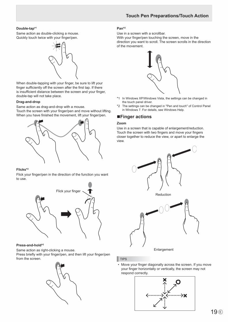
Double-tap*1
Sameactionasdouble-clickingamouse.Quicklytouchtwicewithyourfinger/pen.
Whendouble-tappingwithyourfinger,besuretoliftyourfingersufficientlyoffthescreenafterthefirsttap.Ifthereisinsufficientdistancebetweenthescreenandyourfinger,double-tapwillnottakeplace.
Drag-and-dropSameactionasdrag-and-dropwithamouse.Touchthescreenwithyourfinger/penandmovewithoutlifting.When you havefinishedthemovement,liftyourfinger/pen.
Flicks*2
Flickyourfinger/peninthedirectionofthefunctionyouwantto use.
Flickyourfinger
Press-and-hold*2
Sameactionasright-clickingamouse.Pressbrieflywithyourfinger/pen,andthenliftyourfinger/penfrom the screen.
Pan*2
Use in a screen with a scrollbar.Withyourfinger/pentouchingthescreen,moveinthedirection you want to scroll. The screen scrolls in the direction of the movement.
*1 InWindowsXP/WindowsVista,thesettingscanbechangedinthe touch panel driver.
*2 Thesettingscanbechangedin"Penandtouch"ofControlPanel inWindows7.Fordetails,seeWindowsHelp.
nFinger actionsZoomUse in a screen that is capable of enlargement/reduction.Touchthescreenwithtwofingersandmoveyourfingerscloser together to reduce the view, or apart to enlarge the view.
Reduction
Enlargement
TIPS
• Moveyourfingerdiagonallyacrossthescreen.Ifyoumoveyourfingerhorizontallyorvertically,thescreenmaynotrespond correctly.
Touch Pen Preparations/Touch Action
20E
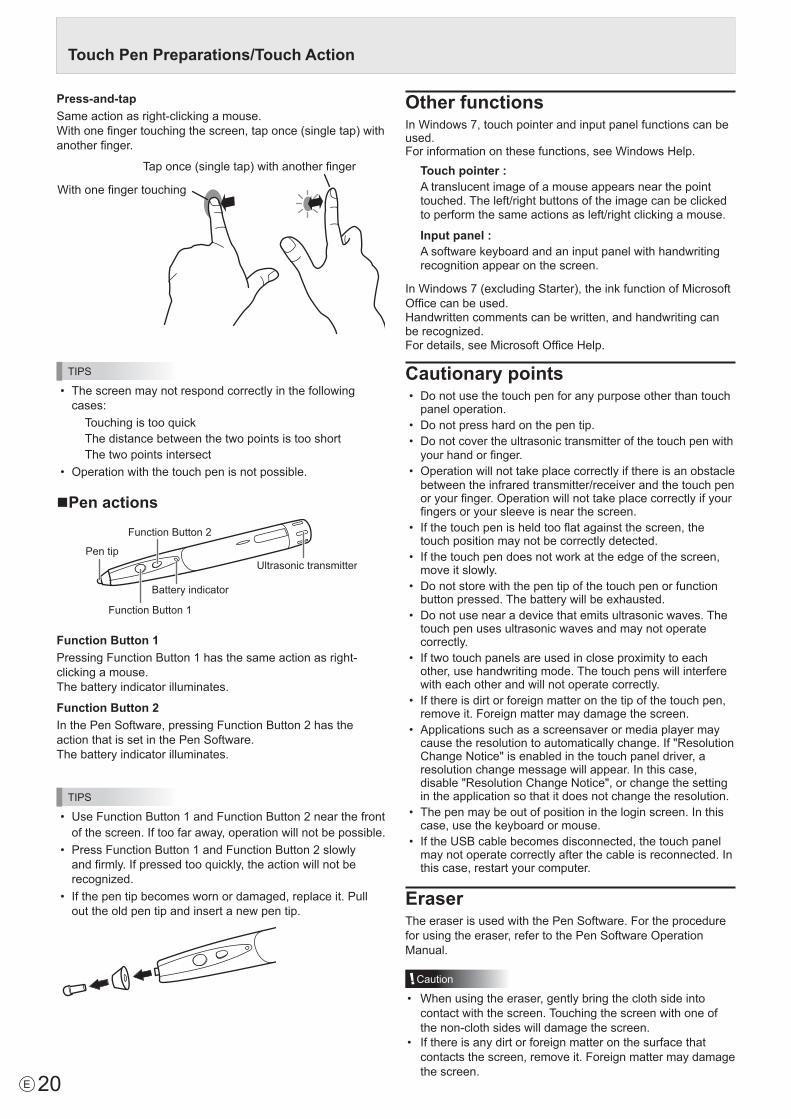
Press-and-tapSameactionasright-clickingamouse.Withonefingertouchingthescreen,taponce(singletap)withanotherfinger.
Withonefingertouching
Taponce(singletap)withanotherfinger
TIPS
• Thescreenmaynotrespondcorrectlyinthefollowingcases:TouchingistooquickThe distance between the two points is too shortThe two points intersect
• Operationwiththetouchpenisnotpossible.
nPen actions
Pen tip
Function Button 2
Function Button 1
Ultrasonic transmitter
Battery indicator
Function Button 1PressingFunctionButton1hasthesameactionasright-clicking a mouse.The battery indicator illuminates.
Function Button 2InthePenSoftware,pressingFunctionButton2hastheaction that is set in the Pen Software.The battery indicator illuminates.
TIPS
• UseFunctionButton1andFunctionButton2nearthefrontof the screen. If too far away, operation will not be possible.
• PressFunctionButton1andFunctionButton2slowlyandfirmly.Ifpressedtooquickly,theactionwillnotberecognized.
• Ifthepentipbecomeswornordamaged,replaceit.Pullout the old pen tip and insert a new pen tip.
Other functionsInWindows7,touchpointerandinputpanelfunctionscanbeused.Forinformationonthesefunctions,seeWindowsHelp.
Touch pointer :A translucent image of a mouse appears near the point touched. The left/right buttons of the image can be clicked to perform the same actions as left/right clicking a mouse.
Input panel :A software keyboard and an input panel with handwriting recognition appear on the screen.
InWindows7(excludingStarter),theinkfunctionofMicrosoftOfficecanbeused.Handwritten comments can be written, and handwriting can berecognized.Fordetails, see MicrosoftOfficeHelp.
Cautionary points• Donotusethetouchpenforanypurposeotherthantouch
panel operation.• Donotpresshardonthepentip.• Do not cover the ultrasonic transmitter of the touch pen with
yourhandorfinger.• Operation will not take place correctly if there is an obstacle
between the infrared transmitter/receiver and the touch pen oryourfinger.Operationwillnottakeplacecorrectlyifyourfingers or your sleeve is near the screen.
• Ifthetouchpenisheldtooflatagainstthescreen,thetouch position may not be correctly detected.
• Ifthetouchpendoesnotworkattheedgeofthescreen,move it slowly.
• Donotstorewiththepentipofthetouchpenorfunctionbutton pressed. The battery will be exhausted.
• Donotusenearadevicethatemitsultrasonicwaves.Thetouch pen uses ultrasonic waves and may not operate correctly.
• Iftwotouchpanelsareusedincloseproximitytoeachother, use handwriting mode. The touch pens will interfere with each other and will not operate correctly.
• Ifthereisdirtorforeignmatteronthetipofthetouchpen,removeit.Foreignmattermaydamagethescreen.
• Applicationssuchasascreensaverormediaplayermaycausetheresolutiontoautomaticallychange.If"ResolutionChangeNotice"isenabledinthetouchpaneldriver,aresolution change message will appear. In this case, disable"ResolutionChangeNotice",orchangethesettingin the application so that it does not change the resolution.
• Thepenmaybeoutofpositionintheloginscreen.Inthiscase, use the keyboard or mouse.
• IftheUSBcablebecomesdisconnected,thetouchpanelmay not operate correctly after the cable is reconnected. In this case, restart your computer.
EraserTheeraserisusedwiththePenSoftware.Fortheprocedurefor using the eraser, refer to the Pen Software Operation Manual.
Caution
• Whenusingtheeraser,gentlybringtheclothsideintocontact with the screen. Touching the screen with one of thenon-clothsideswilldamagethescreen.
• Ifthereisanydirtorforeignmatteronthesurfacethatcontactsthescreen,removeit.Foreignmattermaydamagethe screen.
Touch Pen Preparations/Touch Action

21 E
Basic Operation
1
2 3 4
5
6 7
8
1. INPUT (Input mode selection)The menu is displayed. Press or to select the input mode, and press to enter.* Youcanselecttheinputterminalbypressingtheinput
switch of the monitor.Input mode Video Audio
PCD-SUB PCD-subinputterminal*1 Audio input terminalPCHDMI PC/AVHDMIinputterminal*2
*3AVHDMI PC/AVHDMIinputterminal*2
AVCOMPONENT PCD-subinputterminal*1Audio input terminal
AVVIDEO PCD-subinputterminal*1
When the PN-ZB01 (optional) is attachedInput mode Video Audio
PCDVI-D PC/AVDVI-Dinputterminal*4
*3
PCHDMI PC/AVHDMIinputterminal*2
PCD-SUB PCD-subinputterminal*1
PCRGB PCRGBinputterminals*5
AVDVI-D PC/AVDVI-Dinputterminal*4
AVHDMI PC/AVHDMIinputterminal*2
AVCOMPONENTAVCOMPONENTinputterminals*5
PCD-subinputterminal*1
AVS-VIDEO AVS-videoinputterminal
AVVIDEOAVvideoinputterminalPCD-subinputterminal*1
*1 SelecttheterminaltobeusedinD-SUBofINPUTSELECT.(Seepage26.)
*2 SelecttheterminaltobeusedinHDMIofINPUTSELECT.(Seepage26.)
*3 SelecttheterminalforAUDIOSELECTwhichisusedforaudioinput.(Seepage26.)
*4 SelecttheterminaltobeusedinDVIofINPUTSELECT.(Seepage26.)
*5 SelecttheterminaltobeusedinBNCofINPUTSELECT.(Seepage26.)
2. MUTETurns off the volume temporarily.PresstheMUTEbuttonagaintoturnthesoundbacktotheprevious level.
3. MENUDisplaysandturnsoffthemenuscreen.(seepage23.)
4. VOL +/- (Volume adjustment)Pressing or displaystheVOLUMEmenuwhenthemenu screen is not displayed.
V O L U M E 15
Press or toadjustthevolumeofthesound.* Ifyoudonotpressanybuttonsforabout4seconds,theVOLUMEmenuautomaticallydisappears.
5. BRIGHT +/- (Backlight adjustment)Pressing or displaystheBRIGHTmenuwhenthemenu screen is not displayed.
B R I G H T 15
Press or toadjustthebrightness.* Ifyoudonotpressanybuttonsforabout4seconds,theBRIGHTmenuautomaticallydisappears.
6. SIZE (Screen size selection)The menu is displayed.Press or toselectthescreensize.(Seepage22.)
7. DISPLAYDisplaysmonitorinformation.Whenyoupressthisbuttonagain, the display disappears.WhenthePN-ZB01(optional)isattached,thedisplaychangesfromINFORMATION1→INFORMATION2→cleardisplay,and so on every time you press this button.• Thedisplaydisappearsautomaticallyafterabout15
seconds.• LAN is displayed during LAN communication.• If LAN is displayed in red, there is a duplicate IP address.
8. MODE (Color mode selection)Eachtimeyoupressthisbutton,thecolormodechangesinthe following order:
STD(Standard)→VIVID→sRGB→STD...
• sRGBappliestoPCinputonly. sRGBisinternationalstandardofcolorrepresentationspecifiedbyIEC(InternationalElectrotechnicalCommission).Colorconversionismadeintakingaccountofliquidcrystal’scharacteristicsandrepresentscolortoneclose to its original image.
22E
Basic Operation
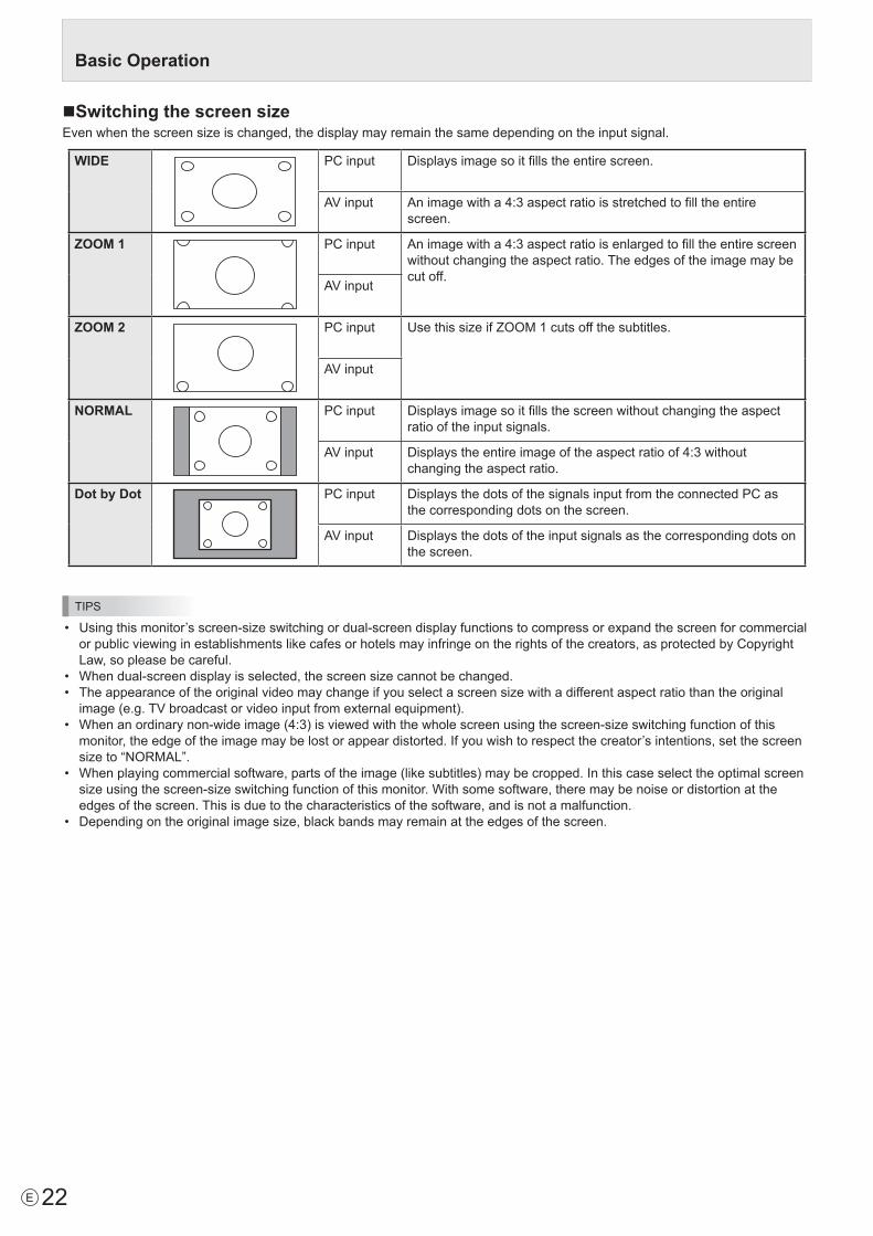
nSwitching the screen sizeEvenwhenthescreensizeischanged,thedisplaymayremainthesamedependingontheinputsignal.
WIDE PCinput Displaysimagesoitfillstheentirescreen.
AVinput Animagewitha4:3aspectratioisstretchedtofilltheentirescreen.
ZOOM 1 PCinput Animagewitha4:3aspectratioisenlargedtofilltheentirescreenwithout changing the aspect ratio. The edges of the image may be cut off.
AVinput
ZOOM 2 PCinput UsethissizeifZOOM1cutsoffthesubtitles.
AVinput
NORMAL PCinput Displaysimagesoitfillsthescreenwithoutchangingtheaspectratio of the input signals.
AVinput Displaystheentireimageoftheaspectratioof4:3withoutchanging the aspect ratio.
Dot by Dot PCinput DisplaysthedotsofthesignalsinputfromtheconnectedPCasthe corresponding dots on the screen.
AVinput Displaysthedotsoftheinputsignalsasthecorrespondingdotsonthe screen.
TIPS
• Usingthismonitor’sscreen-sizeswitchingordual-screendisplayfunctionstocompressorexpandthescreenforcommercialorpublicviewinginestablishmentslikecafesorhotelsmayinfringeontherightsofthecreators,asprotectedbyCopyrightLaw, so please be careful.
• Whendual-screendisplayisselected,thescreensizecannotbechanged.• Theappearanceoftheoriginalvideomaychangeifyouselectascreensizewithadifferentaspectratiothantheoriginalimage(e.g.TVbroadcastorvideoinputfromexternalequipment).
• Whenanordinarynon-wideimage(4:3)isviewedwiththewholescreenusingthescreen-sizeswitchingfunctionofthismonitor, the edge of the image may be lost or appear distorted. If you wish to respect the creator’s intentions, set the screen sizeto“NORMAL”.
• Whenplayingcommercialsoftware,partsoftheimage(likesubtitles)maybecropped.Inthiscaseselecttheoptimalscreensizeusingthescreen-sizeswitchingfunctionofthismonitor.Withsomesoftware,theremaybenoiseordistortionattheedges of the screen. This is due to the characteristics of the software, and is not a malfunction.
• Dependingontheoriginalimagesize,blackbandsmayremainattheedgesofthescreen.

23 E
Menu ItemsDisplaying the menu screenVideoandaudioadjustmentandsettingsofvariousfunctionsare enabled. This section describes how to use the menu items.Seepages24to27fordetailsofeachmenuitems.
Caution
• Donotturnthemainpowerswitchoffwhilethemenuitemsarebeingdisplayed.Doingsomayinitializethesettings.
nExample of operation(AdjustingCONTRASTinthePICTUREmenu)1. Press
MENU to display the menu screen.
1 9 2 0 x 1 0 8 0 V: 60 Hz H: 67.5 kHz
AUTOCLOCKPHASEH-POSV-POSH-SIZEV-SIZEH-RESOLUTIONV-RESOLUTIONRESET
SCREEN
PICTURE
AUDIO
SETUP
OPTION
PIP/PbyP
60025
610375050
19201080
SCREEN 1/1
END···[MENU]
PC D-SUB
2. Press or to select PICTURE, and press .
3. Press or to select CONTRAST.
AUTOANALOG GAINANALOG OFFSETBRIGHTCONTRASTBLACK LEVELTINTCOLORSSHARPNESSRGB INPUT RANGE
6486313030303012
1/2
FULL
PC D-SUBPICTURESCREEN
PICTURE
AUDIO
SETUP
OPTION
PIP/PbyP
OK···[MENU]MOVE OSD···[DISPLAY]1 9 2 0 x 1 0 8 0 V: 60 Hz H: 67.5 kHz
4. Press or to adjust the setting.
▲
▲
▲
AUTOANALOG GAINANALOG OFFSETBRIGHTCONTRASTBLACK LEVELTINTCOLORSSHARPNESSRGB INPUT RANGE
6486314030303012
1/2
FULL
PC D-SUBPICTURESCREEN
PICTURE
AUDIO
SETUP
OPTION
PIP/PbyP
OK···[MENU]MOVE OSD···[DISPLAY]1 9 2 0 x 1 0 8 0 V: 60 Hz H: 67.5 kHz
Foritemsthathave , press , make settings and then press
MENU.
5. Press MENU
twice to close the menu screen.
TIPS
• Themenuwilldifferdependingontheinputmode.• Themenuscreenwillcloseautomaticallyifnooperationisperformedforabout15seconds.(DATE/TIMESETTING,SCHEDULEandLANSETUPscreenswillcloseinabout4minutes.)
nMenu screen display
▲
▲
▲
AUTOANALOG GAINANALOG OFFSETBRIGHTCONTRASTBLACK LEVELTINTCOLORSSHARPNESSRGB INPUT RANGE
6486313030303012
1/2
FULL
PC D-SUBSCREEN
PICTURE
AUDIO
SETUP
OPTION
PIP/PbyP
PICTURE
OK···[MENU]MOVE OSD···[DISPLAY]1 9 2 0 x 1 0 8 0 V: 60 Hz H: 67.5 kHz
1 23
4
1 Nameofthemenu2 Inputmode3 Anitembeingselected(highlighted)4 Screen resolution of input signal, and other data.
TIPS
• Itemsthatcannotbeselectedappearingray. (e.g.Functionnotsupportedbythecurrentinputsignal)
nMenu ItemsThe displayed menu items vary depending on whether or not thePN-ZB01(optional)isattached.ThefollowingmenuswillbedisplayedonlywhenthePN-ZB01(optional)isattached.
Menu ItemSETUP HOTPLUGCONTROL DVI
RS-232C/LANSELECTLANSETUPSPEAKERSELECT
OPTION INPUTSELECT DVIBNC
AUDIOSELECT PCDVI-DPCD-SUBPCRGBAVDVI-DAVCOMPONENT(BNC)AVCOMPONENT(D-SUB)AVS-VIDEOAVVIDEO(BNC)AVVIDEO(D-SUB)
PIP/PbyP PIPSOURCE

24E
Menu item detailsThe menu will differ depending on the input mode.
nSCREENYou can move the menu screen display position each time DISPLAY is pressed.
AUTO (PC D-SUB/PC RGB)TheCLOCK,PHASE,H-POS,andV-POSareautomaticallyadjusted.Pressing performsadjustment.UsethisautomaticadjustmentwhenyouusethePCD-subinputterminalorPCRGBinputterminalstodisplayaPCscreenforthefirsttimeorwhenyouchangethesettingofthePC.(Seepage30.)CLOCK (PC D-SUB/PC RGB)Adjustsfrequencyfor sampling clock for applicable video.Adjustwhenthereisflickeringintheformofverticalstripes.Whenusingtheadjustmentpattern(seepage30),makeadjustmentssothatno vertical stripe noise appears in it.PHASE (PC D-SUB/PC RGB)Adjustssamplingclockphaseforapplicablevideo.Useful when small characters appear with low contrast and/orthereareflickersatcorners.Whenusingtheadjustmentpattern(seepage30),makeadjustmentssothatnohorizontalstripenoiseappearsinit.* AdjustmentstoPHASEshouldbemadeonlyafterCLOCK
has been correctly set.H-POSAdjustthehorizontalpositionoftheimage.V-POSAdjusttheverticalpositionoftheimage.H-SIZEAdjustthehorizontalsizeoftheimage.V-SIZEAdjusttheverticalsizeoftheimage.H-RESOLUTION (PC D-SUB/PC RGB)Sets properhorizontalresolutionwhentheresolutionofinputsignalsisnotrecognizedproperly.(Adjustmentmaybeimpossible with somesignals.)V-RESOLUTION (PC D-SUB/PC RGB)Sets proper vertical resolution when the resolution of input signalsisnotrecognizedproperly.(Adjustmentmaybeimpossible with somesignals.)RESETResetsthevaluesoftheSCREENmenuitemstothefactorypreset values.Select “ON” and then press
MENU.
nPICTUREYou can move the menu screen display position each time DISPLAY is pressed.
AUTO (PC D-SUB/PC RGB)The ANALOGGAINandANALOGOFFSETareautomaticallyadjusted.Pressing performsadjustment.ANALOG GAIN (PC D-SUB/PC RGB)Adjuststhebrightportionsofthevideoinputsignal.ANALOG OFFSET (PC D-SUB/PC RGB)Adjuststhedarkportionsofthevideoinputsignal.BRIGHTAdjuststhebacklightbrightness.(InPIPmode,themainsidesettingisreflectedintheimage.)CONTRASTAdjuststhedifferencebetweenthebrightanddarkportionsof the image.BLACK LEVELAdjuststheentirebrightnessofthevideosignals.TINTAdjuststhehue.Selecting+changesthecolortowardsgreen,andselecting-changesittowardsmagenta.COLORSAdjuststhecolorintensity.SHARPNESSAdjuststhesharpnessoftheimage.RGB INPUT RANGE (PC DVI-D/PC HDMI/PC D-SUB/PCRGB/AV DVI-D/AV HDMI)SetstheRGBinputsignalrange.WhenusingHDMIsettoAUTO,theRGBinputsignalisdetectedautomatically.UseAUTO normally.IftheRGBinputsignalrangecannotbesetappropriatelyevenwhenusingAUTO,setaccordingtotheimage.Whenthe setting is different, images will be displayed with washed out blacks and compressed gradients.ADVANCED (AV input)Youcanadjustmorespecifically.(Seepage30.)COLOR MODEChanges the color mode on the screen. The color mode on the screen can also be changed using a remote control unit. (Seepage21.)* sRGBisPCinputonly.Seepage21fordetails.(InPIPmode,themainsidesettingisreflectedintheimage.)WHITE BALANCETHRU .............. Displaystheinputsignallevelasis.(forPC
DVI-D/PCHDMIonly)PRESET ......... SelectsthecolortemperatureusingPRESET.USER .............. UsedforadjustingR-/G-/B-CONTRASTand
R-/G-/B-OFFSETrespectively.(InPIPmode,themainsidesettingisreflectedintheimage.)PRESETSelectsthecolortemperaturewhentheWHITEBALANCEissettoPRESET.The setting values are shown for reference. The color temperature of the screen varies over time.This function is not intended to keep the color temperature constant.
Menu Items

25 E
USERAdjustseachitemwhentheWHITEBALANCEissettoUSER.R-CONTRAST ....Adjustsbright-tonedredcomponent.G-CONTRAST ....Adjustsbright-tonedgreencomponent.B-CONTRAST ....Adjustsbright-tonedbluecomponent.R-OFFSET ..........Adjustsdark-tonedredcomponent.G-OFFSET .........Adjustsdark-tonedgreencomponent.B-OFFSET ..........Adjustsdark-tonedbluecomponent.COPY TO USERCopiesthevalueofwhitesetforPRESETtotheUSERsetting.Select “ON” and then press MENU .(Inthecaseotherthanwhite,colortonemaydifferfromthePRESET.)GAMMASelectsthegamma.USERsetsthegammatothesentvalue(seepage35).(InPIPmode,themainsidesettingisreflectedintheimage.)DISPLAY COLOR PATTERNDisplaysacolorpattern.Canbedisplayedwhilethemenuscreen is displayed, so you can refer to the pattern whileadjustingtheimage.OFF ..............No pattern display.WHITE ..........Whitesinglecolorpatterndisplay.RED ..............Red single color pattern display.GREEN .........Greensinglecolorpatterndisplay.BLUE ............Bluesinglecolorpatterndisplay.USER............Red/green/blue mixed color pattern display.
WhenUSERisselected,seteachcolor’slevel.
RESETResetsthevaluesofthePICTUREmenuitemstothefactorypreset values.Select “ON” and then press
MENU.
nAUDIOTREBLEAdjuststhevolumeoftreble-levelsound.BASSAdjuststhevolumeofbass-levelsound.BALANCEAdjuststhebalanceoftheaudiosoundbetweenrightandleft.RESETResetsthevaluesoftheAUDIOmenuitemstothefactorypresetvalues.Select “ON” and then press MENU .
nSETUPOSD H-POSITIONAdjuststhehorizontaldisplaypositionofmenuscreen.OSD V-POSITIONAdjuststheverticaldisplaypositionofmenuscreen.MONAURAL AUDIOOutputs audio signals as monaural.LANGUAGESets the display language for the menu screen.POWER ON DELAYYou can delay the screen display after the monitor is turned on.Theperiodcanbesetupto60secondsinunitsofonesecond.Whenthisfunctionisactivated,thepowerLEDflashes(atapprox.1secondinterval)inorange.Thisfunctionisdisabledwhen0isspecified.OPERATION MODEMODE1 ......OFFIFNOOPERATIONissettoON,and
STANDBYMODEissettoLOWPOWER. (Thesesettingscannotbechanged.)
MODE2 ......Willperformstandardoperation. OFFIFNOOPERATIONissettoOFF,andSTANDBYMODEissettoSTANDARD.Thesesettings can be changed.
STANDBY MODEWhenSTANDARDisselected,startuptimefromstandbymode is reduced. Note, however that, more power will be consumed in standby mode.WhenLOWPOWERisselected,currentconsumptionis reduced while the monitor is in standby mode. Note, however, that the startup time from standby mode becomes longer. IfsettoLOWPOWER,certainRS-232Ccommandscannotbe used in standby mode, and control via LAN will be disabled.OFF IF NO OPERATIONDetermineswhetherornottosetthemonitortogointostandby mode when there is no operation from the remote controlunit,RS-232Ccommands,orLANforover4hours.
Menu Items

26E
Menu Items
nOPTIONDATE/TIME SETTING
Set the date and time. Press or to select the date and time, and press or to change the numerical values.Set the date in “Day/Month/Year” order.Set the time on a 24-hour basis. (Factory default)DATE/TIME FORMATSets the date/time display format.DATE ..................MM/DD/YYYY
DD/MM/YYYYYYYY/MM/DD(YYYY: Year, MM: Month, DD: Day)
TIME ...................Select 12- or 24-hour time.SCHEDULE (See page 29.)You can turn the power on/off and change the screen brightness at a specified time.INPUT SELECTSelect the input mode to be used in PC D-Sub input terminal, PC/AV DVI-D input terminal, PC/AV HDMI input terminal and PC RGB/AV component input terminals.For D-SUB, select SET after selecting the input mode, and then press MENU .D-SUB and BNC cannot be set to AV COMPONENT at the same time.If D-SUB is set to AV VIDEO, the AV VIDEO input terminal cannot be used for BNC.AUDIO SELECTSelects the terminal used to input audio signals in each input mode.INPUT SIGNAL (PC D-SUB/PC RGB)If a computer connected to the PC D-sub/PC RGB input terminal outputs any of the following resolutions, make a selection from the following options.480 LINES .......... AUTO, 640x480 or 848x480768 LINES ..........AUTO, 1024x768, 1280x768, or 1360x7681050 LINES ........1400x1050 or 1680x1050ZOOM2 SPECIAL SETTING (See page 28.)SCAN MODE (AV input)Sets the scan mode used for AV mode input.MODE1 ............... Over-scan displayMODE2 ...............Under-scan displayMODE3 ............... Under-scan display when the input signal
is 1080i/p. Otherwise, over-scan display* Even when MODE1 is selected, under-scan display is used when
the input signal is 1080i/p and the screen size is Dot by Dot.POWER MANAGEMENTPOWER MANAGEMENT determines whether or not to switch modes from no signal to the input signal standby mode.COLOR SYSTEM (AV S-VIDEO/AV VIDEO)Select the color system of the AV equipment which is connected to AV S-video and AV video input terminal. (AUTO / PAL / PAL-60 / SECAM / NTSC3.58 / NTSC4.43) When AUTO is selected, the color system is automatically set according to the input signal.
HOT PLUG CONTROLSets whether to use hot plug control for the PC/AV HDMI and PC/AV DVI-D input terminals.RS-232C/LAN SELECTSelects the method with which to control the monitor from the computer.ID No. SETAssigns ID numbers to monitors connected in a daisy chain (see page 33), using RS-232 cables.The numbers 1 to 255 are available for ID numbers.If “0” is set, the system regards this as the state where no ID number is set.AUTO ASSIGN ID No.ID No. to be used will be automatically assigned when multiple monitors are connected with RS-232C.Select ON, then press MENU . Perform operations using the first monitor in the daisy chain.BAUD RATESelects the communication speed used for RS-232C communication.LAN SETUPConfigures the settings to control the monitor from the computer via LAN. (See page 43.)AUTO ASSIGN FIXED IP ADDR.Can be enabled when RS-232C/LAN SELECT is LAN and the DHCP CLIENT is OFF.Set DHCP CLIENT to OFF for the monitor connected to the RS-232C output terminal and the daisy chain of connected monitors that follows. Fixed IP addresses are automatically allocated.If the IP address is a duplicate with a network device other than a monitor, individually change the IP address.SPEAKER SELECTSelects the speaker to be used.HDMI AUTO VIEWWhen ON is selected, the screen size is adjusted automatically according to the screen size control signal included in the video signal input from the AV HDMI input terminal.COPY SETTING VALUEWhen the monitor has been connected to multiple monitors by RS-232C, the settings in the monitor can be copied to the monitor connected to the RS-232C output terminal and to the daisy chain of connected monitors that follows.Selects the settings to copy with COPY SETTING VALUE TARGET.“PICTURE” ONLY ..... Copies the PICTURE menu settings.*ALL ........................... Copies all the settings.*Select the ID No. of the monitor that you would like copy to with COPY TO ID No., then select COPY and press MENU .If you select ALL, settings will be copied to all monitors.When you would like to confirm the ID No. that is set to the monitor, select ID No. DISPLAY and press . The ID No. will be displayed on the screen.* Certain setting details such as ANALOG GAIN, ANALOG
OFFSET, and DISPLAY COLOR PATTERN cannot be copied.
LOGO SCREENSets whether or not to display the logo screen.

27 E
Menu Items
AUDIO OUTPUT (RCA)Sets the volume of sound output from the audio output terminals.WhensettoVARIABLE2,soundwillnotbeoutputfromthebuilt-inspeakerortheexternalspeakerterminal.VARIABLE1 ........ YoucanadjustthevolumeusingVOLUME.VARIABLE2 ........ YoucanadjustthevolumeusingVOLUME.FIXED .................Fixesthesounds.AUDIO LEVEL (STEREO MINI)Selects the maximum audio input level of the audio input terminal.SELF ADJUSTOn a PCD-SUB/PCRGB screen, specify whether to performscreenadjustmentautomaticallyornot.WhenONisselected,thescreenisautomaticallyadjustedwhenitsresolutionis800x600orhigherandthetimingofinputsignalschanges.“ADJUSTING”appearsonthescreenduringtheadjustment.Forimageswithblackedges,etc.,dependingonthesignal,adjustmentmaynotbepossible.InthiscaseselectOFF.(Performmanualadjustmentofthescreen.)AUTO INPUT CHANGESpecifywhethertochangeinputsautomatically.WhenONisselected and no signal is present in the selected input mode, AUTOINPUTCHANGEautomaticallychangestheselectedmode to another mode where a video signal is present.Whenvideosignalsexistinmultipleinputmodes,theswitching priority is as follows:PCD-SUB,PCHDMI,AVHDMI,AVCOMPONENTandAVVIDEO
WhenthePN-ZB01(optional)isattached:PCDVI-D,PCHDMI,PCD-SUB,PCRGB,AVDVI-D,AVHDMI,AVCOMPONENT,AVS-VIDEOandAVVIDEO(Inputmodeswitchingmaytake15secondsormore,dependingontheconnectedequipment.Inputsignalsmay not be detected properly and a priority may change, dependingontheconnectedequipmentorvideosignals.)TOUCH PANEL MODE (PC input)Whentheresolutionis1920x1080,settingthistoONimproves touch panel tracking.Whentwoscreensaredisplayed,orwhenV-POSorV-SIZEisadjustedontheSCREENmenu,thescreenmaybecomedistorted.Inthisvent,settoOFF.
nPIP/PbyPPIP MODESSets the display method.OFF .........Displaysonescreen.PIP ...........Displaysasubscreeninsideamainscreen.PbyP ........Displaysamainscreenandasubscreeninaline.PbyP2 ......Displaysamainscreenwhichmeasures1280pixels
in the longest direction and a sub screen in a line.PIP SIZESetsthesizeofthesubscreeninPIPmode.PIP H-POSAdjuststhehorizontalpositionofthesubscreeninPIPmode.PIP V-POSAdjuststheverticalpositionofthesubscreeninPIPmode.PIP BLENDIn PIP mode, use this menu item to display the sub screen transparently.PIP SOURCESelects the input signal of the sub screen in PIP, PbyP, or PbyP2mode.SOUND CHANGESetsthesoundwhichisoutputinPIP,PbyP,orPbyP2mode.If the main screen is displayed as a full screen by the AUTO OFFfunction,thesoundforthemainscreenisoutputevenwhenthesoundforthesubscreenisspecified.MAIN POSSetsthepositionofthemainscreeninPbyPorPbyP2mode.PbyP2 POSSetsthepositionofthesubscreeninPbyP2mode.AUTO OFFSets the display method when no signals for the sub screen areinputinPIP,PbyP,orPbyP2mode.MANUAL ....... Displaysamainscreenandablacksubscreen.AUTO ............Displaysthemainscreenasafullscreen.
TIPS
• WhenWHITEBALANCEissettoTHRU,BLACKLEVEL,CONTRAST,TINT,COLORS,RGBINPUTRANGE,GAMMAandCOPYTOUSERcannotbeset.
• IfCOLORMODEissettosRGB,thefollowingitemscannotbe set. WHITEBALANCE,PRESET,USER,COPYTOUSER,andGAMMA
• WhentheCOLORMODEissettoVIVID,GAMMAcannotbeadjusted.
• STANDBYMODEcannotbesettoLOWPOWERwhenSCHEDULEiseffectiveorwhenOFFisselectedforLEDinFUNCTION.
• Whendisplayingthecolorpattern,itispossibletoadjustcertainitemsofthePICTUREmenu. Non-adjustableitemscannotbeselected. AudioinputfromtheHDMIinputterminalisalsonotoutput.
28E
Menu Items
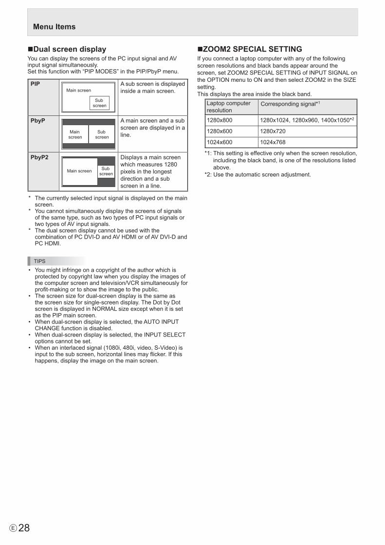
nDual screen displayYoucandisplaythescreensofthePCinputsignalandAVinput signal simultaneously.Setthisfunctionwith“PIPMODES”inthePIP/PbyPmenu.
PIPMain screen
Sub screen
A sub screen is displayed inside a main screen.
PbyP
Main screen
Sub screen
A main screen and a sub screen are displayed in a line.
PbyP2
Main screen Sub screen
Displaysamainscreenwhichmeasures1280pixels in the longest direction and a sub screen in a line.
* Thecurrentlyselectedinputsignalisdisplayedonthemainscreen.
* Youcannotsimultaneouslydisplaythescreensofsignalsofthesametype,suchastwotypesofPCinputsignalsortwotypesofAVinputsignals.
* ThedualscreendisplaycannotbeusedwiththecombinationofPCDVI-DandAVHDMIorofAVDVI-DandPCHDMI.
TIPS
• Youmightinfringeonacopyrightoftheauthorwhichisprotected by copyright law when you display the images of thecomputerscreenandtelevision/VCRsimultaneouslyforprofit-makingortoshowtheimagetothepublic.
• Thescreensizefordual-screendisplayisthesameasthescreensizeforsingle-screendisplay.TheDotbyDotscreenisdisplayedinNORMALsizeexceptwhenitissetas the PIP main screen.
• Whendual-screendisplayisselected,theAUTOINPUTCHANGEfunctionisdisabled.
• Whendual-screendisplayisselected,theINPUTSELECToptions cannot be set.
• Whenaninterlacedsignal(1080i,480i,video,S-Video)isinputtothesubscreen,horizontallinesmayflicker.Ifthishappens, display the image on the main screen.
nZOOM2 SPECIAL SETTINGIf you connect a laptop computer with any of the following screen resolutions and black bands appear around the screen,setZOOM2SPECIALSETTINGofINPUTSIGNALontheOPTIONmenutoONandthenselectZOOM2intheSIZEsetting.This displays the area inside the black band.
Laptop computer resolution
Correspondingsignal*1
1280x800 1280x1024,1280x960,1400x1050*2
1280x600 1280x720
1024x600 1024x768
*1:Thissettingiseffectiveonlywhenthescreenresolution,including the black band, is one of the resolutions listed above.
*2:Usetheautomaticscreenadjustment.

29 E
nSCHEDULEYou can set the time to switch the monitor on and off.Setthisfunctionwith“SCHEDULE”intheOPTIONmenu.(Seepage26.)
- :– – – – – – – – – –– – – – –
SCHEDULE
No. POWER DAY OF THE WEEK TIME INPUT BRIGHT
– –/– –/– – – – – – – – –:– –:– –PC D-SUB
(1)–
- :– – – – – – – – – –– – – – ––- :– – – – – – – – – –– – – – ––- :– – – – – – – – – –– – – – ––- :– – – – – – – – – –– – – – ––- :– – – – – – – – – –– – – – ––- :– – – – – – – – – –– – – – ––- :– – – – – – – – – –– – – – ––
(5)(2) (3) (4) (6)
OK···[MENU]1 9 2 0 x 1 0 8 0 V: 60 Hz H: 67.5 kHz
1. Press or to select the SCHEDULE number, and press .
2. Set the SCHEDULE.(Seethedescriptionbelow.)Press or to select items, and press or to change the setting.
3. Press MENU .SCHEDULEbecomeseffective.
(1)●:SCHEDULEeffective-:SCHEDULEnoteffective(2) POWERON : Switchesthemonitoronatthespecifiedtime.OFF: Switchesthemonitoroffatthespecifiedtimeandputs
the monitor in standby mode.(3) DAY OF THE WEEKSpecifiesthedayoftheweektoexecutetheSCHEDULE.0:ONLYONCEExecutestheSCHEDULEonceonthespecifiedday.SpecifythedayoftheweektoexecutetheSCHEDULE.
1:EVERYWEEKExecutestheSCHEDULEonthespecifieddayoftheweekevery week. Specify the day of the week to execute the SCHEDULE. Periodicsettingsuchas“MondaythroughFriday”isalsopossible.
2:EVERYDAYExecutestheSCHEDULEeverydayregardlessofthedayof the week.
(4) TIMESpecifiesthetimetoexecutetheSCHEDULE.Setthetimeona24-hourbasis.(Factorydefault)Canbeenteredas12-hourtimeusingtheTIMEsettinginDATE/TIMEFORMAT.(5) INPUTSpecifiestheinputmodeatpower-on.Whennotspecifying,thescreenatthepreviouspower-offappears.InputmodesdisplayedonDVI,HDMI,BNCandD-SUBdependonINPUTSELECTsettings.(6) BRIGHTSets the brightness when changing the screen brightness at aspecifiedtime.
Menu Items
Caution
• DonotswitchoffthemainpoweraftersettingtheSCHEDULE.
• Specifythecorrectdateandtime.(Seepage26.) SCHEDULEdoesnotfunctionunlessthedateandtimearespecified.
• Checkregularlythatthesetdateandtimearecorrect.• WhenSTANDBYMODEisLOWPOWER,SCHEDULE
cannot be set.• Whenatemperatureabnormalityoccursandthebacklight
brightness is reduced, the brightness is not changed even ifaschedulesettoBRIGHTisexecuted.
TIPS
• Upto8SCHEDULEitemscanberegistered.• SettingtheSCHEDULEflashesthepowerLEDalternately
in red and orange in standby mode.• ASCHEDULEthathasalargenumberhasprecedence
over that of a small number when schedules overlap.• IfD-SUBofINPUTSELECTontheOPTIONmenuissettoAVVIDEO,theinputmodewillswitchtoAVVIDEO(D-SUB)regardlessifsettoD-SUBorVIDEO.

30E
nADVANCED items (AV input) (See page 24 for additional Menu item details.)FLESH TONEAdjustthehuecontrol.3D-NRReduce the noise of playback images on video.Setting a higher level reduces more noise. However, it may cause blurring on an image.MPEG-NRReduce block noise caused by digital compression.3D-Y/C (AV VIDEO)Specifywhethertoperform3-dimensionY/Cseparation.Ifdotinterferenceorcross-colorisoccurringinfast-motionscenes,selecting“OFF”mayimprovetheimagequality.C.M.S.-HUEAdjustscolortonewith6colorsofR(red),Y(yellow),G(green),C(cyan),B(blue),andM(magenta).C.M.S.-SATURATIONAdjustscolorvividnesswith6colorsofR(red),Y(yellow),G(green),C(cyan),B(blue),andM(magenta).C.M.S.-VALUEAdjustscolorbrightnesswith6colorsofR(red),Y(yellow),G(green),C(cyan),B(blue),andM(magenta).
TIPS
• WhenFLESHTONEissettoLOWorHIGH,C.M.S.-HUE/ -SATURATION/-VALUEcannotbeset.
Adjustments for PC screen displaynAutomatic adjustmentWhenyouusethePCD-subinputterminalorPCRGBinputterminalstodisplayaPCscreenforthefirsttime,orwhenyouchangethesettingofthePC,usetheautomaticscreenadjustment.1. Switch the input to PC D-SUB or to PC RGB and display
the adjustment pattern.(Seethedescriptionbelow.)2. Press MENU and use or to display the SCREEN
menu.3. Press and select “AUTO”.4. Press . Theautomaticadjustmentiscompleteinseveralseconds.5. Press MENU twice to close the menu screen.
TIPS
• Ifthescreencannotbeadjustedproperlywithoneautomaticadjustment,repeattheautomaticadjustmenttwoorthreetimes.Trymanualadjustmentifnecessary.
nScreen display for adjustmentBeforemakingadjustmentsintheSCREENmenuorPICTUREmenu,displayanimagetobrightentheentirescreen.IfyouareusingaWindowsPC,usetheadjustmentpatternonthesuppliedCD-ROM.
Opening the adjustment patternThefollowingexampleisperformedinWindows7.1. Load the supplied CD-ROM into the computer’s CD-
ROM drive.2. Open [CD Drive] in [Computer]. InWindowsXP,open[CDDrive]in[MyComputer].3. Double-click [Adj_uty.exe] in the [Monitor] folder. Theadjustmentpatternwillappear. Adjustthescreenautomaticallyormanually.
4. When adjustment is finished, press the [Esc] on the computer’s keyboard to quit the adjustment program.
5. Eject the CD-ROM from the CD-ROM drive.
TIPS
• Ifthedisplaymodeonthecomputeryouareusingis65,000colors,thecolorlevelsinthecolorpatternmayappear differently or grayscale may appear to be colored. (Thisisduetothespecificationsoftheinputsignalandisnotamalfunction.)
Menu Items

31 E
Youcanreturnthesettingstotheirfactory-presetvaluesandrestrict operations.
1. Hold SIZE down until “F” appears in the upper left corner of the screen.
2. While “F” appears, press , , , in that order.
▲
▲▲
▲▲
▲▲
▲ ▲
▲▲
▲▲
▲▲
OFF
UNLOCKEDON1ONLEDOFF
MONITOR
FUNCTION 1/1
ALL RESETADJUSTMENT LOCKADJUSTMENT LOCK TARGETRS-232COSD DISPLAYLEDTEMPERATUREALERTSTATUSALERTPOWER BUTTONCONTROLLER INPUT
END…[MENU]
3. Select and set the items.ALL RESETResets the settings to the factory default settings. Press ,selectALLRESET,andthenpressMENU .Afterinitialization,turnthemainpowerswitchoffandthen back on.WhenthePN-ZB01(optional)isattached,press , select the resetting method, and then press
MENU.
ALLRESET1 ....Resets all the settings to the factory default settings.
ALLRESET2 ....Returns all settings to the factory default settings except for the following items: LANSETUP,RS-232C/LANSELECT,IDNo.SET,BAUDRATE,NETWORK,MAIL,SERVICE&SUPPORT,andSNMP(Seepage26,andpages47to50.)
ADJUSTMENT LOCKYou can disable operations on the monitor and the remote control unit that use buttons.OFF ...Enablesoperation.ON1 ..Disablesalloperationsotherthanturningpower
on/offandFUNCTION.ON2 ..OnlytheFUNCTIONoperationisenabled.
DisablesalloperationsotherthanFUNCTION(notevenpoweron/off).
ADJUSTMENT LOCK TARGETSets the target to prohibit operation of with ADJUSTMENTLOCK.REMOTECONTROL ..... Prohibits remote control
operationMONITORBUTTONS ... Prohibits monitor button
operationBOTH ............................. Prohibits remote control and
monitor button operationRS-232C(RS-232C/LAN when the PN-ZB01 (optional) is attached)SpecifieswhethertoallowcontrolviaRS-232CorLAN(seepages32and43).
Initialization (Reset)/Functional Restriction Setting (FUNCTION)OSD DISPLAYShows/hides the menu, modes, and messages.TheFUNCTIONscreencannotbehidden.ON1 .............. Shows all menus, modes, and messages.ON2 .............. Hides messages automatically displayed
by the display. Shows messages during operation.
OFF ............... Hides all menus, modes, and messages.LEDSpecifieswhethertolightthepowerLED.OFFcannotbeselectedwhenSTANDBYMODEisLOWPOWER.TEMPERATURE ALERTSelectsthenotificationmethodforanabnormaltemperature.OFF ..............Donotnotifyaboutanabnormal
temperature.OSD&LED ..Whenanabnormaltemperatureis
detected,thepowerLEDflashesinredand green alternately and the screen displaysamessage:TEMPERATURE.
LED...............Whenanabnormaltemperatureisdetected,thepowerLEDflashesinredand green alternately.
STATUS ALERTSelectsthenotificationmethodforahardwareerror.OFF ..............Donotnotifyabouttheerror.OSD&LED ..Whenahardwareerrorisdetected,the
powerLEDflashesinredandthescreendisplaysamessage:STATUS[xxxx].
LED...............Whenahardwareerrorisdetected,thepowerLEDflashesinred.
POWER BUTTONNormally, leave this setting as MONITOR.Whenusinganoptionalpart,ifinstructionappears,change the setting accordingly.CONTROLLER INPUTNormally, you do not need to change this setting.Whenusinganoptionalpart,ifinstructionappears,change the setting accordingly.
4. Press MENU to return to the normal screen.
TIPS
• Whenbothabnormaltemperatureandhardwareerroraredetected,thehardwareerrornotificationoverrides.
• IfTEMPERATUREALERTorSTATUSALERTissettoOSD&LED,alertmessageswillappeareveniftheOSDDISPLAYissettoON2orOFF.

32E
Controlling the Monitor with a PC (RS-232C)YoucancontrolthismonitorfromaPCviaRS-232C(COMport)onthePC.You can also connect multiple monitors via a daisy chain by usingaPC.ByassigningIDnumberstoeachmonitor(seepage33),youcanmakeinputmodeselection/adjustmentorcancheckthestatusofaspecificmonitor.
Precautions when the PN-ZB01 (optional) is attached• TocontrolthemonitorviaRS-232C,setRS-232C/LANSELECTtoRS-232C.
• YoucannotuseRS-232CandLANcontrolsimultaneously.
PC connectionnOne-to-one connection with a PCConnectwithRS-232straightcablebetweenthePC’sCOMport(RS-232Cconnector)andtheRS-232Cinputterminalonthe monitor.
RS-232 straight cable(commercially available)
To COM port
PC
RS-232C input terminal
nDaisy chain connection… Advanced operationConnectwithRS-232straightcablebetweenthePC’sCOMport(RS-232Cconnector)andtheRS-232Cinputterminalonthefirstmonitor.Next,connectRS-232straightcabletothefirstmonitor’sRS-232Coutputterminalandtothesecondmonitor’s RS-232Cinputterminal.Connectinthesamewaytothethirdandsubsequentmonitors.Upto25monitorscanbeconnected.(Dependingonthelengthofthecableusedandthesurroundingenvironment.)
To COM portRS-232 straight cables(commercially available)
PC
First monitor Second monitor
RS-232Cinput terminal
RS-232Coutput terminal
Communication conditionsSettheRS-232CcommunicationsettingsonthePCtomatchthe monitor’s communication settings as follows:
Baudrate * Stop bit 1bit
Datalength 8 bits Flowcontrol None
Parity bit None
*SettothesamebaudrateastheBAUDRATEsettingofSETUPmenu.(Initialsetting:38400bps)
*Whenconnectingmultiplemonitorsinadaisychain,setallmonitorstothesameBAUDRATE.
Communication procedurenCommand formatWhenacommandissentfromthePCtothemonitor,themonitor operates according to the received command and sendsaresponsemessagetothePC.
C1 C2 C3 C4 P1 P2 P3 P4
Return code
Command field (4 prescribed
alphanumerical characters)
Parameter field (4 character string comprised of:
0-9, +, -, space, ?)
Example:VOLM0030 VOLM 30
* Besuretoinput4charactersfortheparameter.Padwithspaces(“ ”)ifnecessary. (“ ”isareturncode(0DH,0AHor0DH))Wrong :VOLM30Right :VOLM 30
Wheninputtinganegativevalue,specifyanumericalvalueinthree digits.
Example:AUTR-005
DonotusespacesforMPOS,DATE,andSC01throughSC08.Specifyparametersusingaspecifiednumberofcharacters.
Example:MPOS010097
Ifacommandhas“R”listedfor“DIRECTION”inthe “RS-232Ccommandtable”onpage36,thecurrentvaluecanbe returned by using “?” as the parameter.
Example:
VOLM???? ← FromPCtomonitor(Howmuchiscurrentvolumesetting?).
30 ← FrommonitortoPC(Currentvolumesetting:30).
* IfanIDnumber(seepage33)hasbeenassigned (Forexample,IDnumber=1).
VOLM ? ← FromPCtomonitor.
30 001 ← FrommonitortoPC.

33 E
Controlling the Monitor with a PC (RS-232C)
nResponse code formatWhen a command has been executed correctly
O K Return code(0DH, 0AH)
A response is returned after a command is executed.* IfanIDnumberhasbeenassigned
O K SPC 0 0 1
ID number of responding monitor
Space (20H) Return code(0DH, 0AH)
When a command has not been executed
R R E Return code(0DH, 0AH)
* IfanIDnumberhasbeenassigned
R R E SPC 0 0 1
ID number
Space (20H) Return code(0DH, 0AH)
TIPS
• “ERR”isreturnedwhenthereisnorelevantcommandorwhen the command cannot be used in the current state of the monitor.
• IfcommunicationhasnotbeenestablishedforreasonssuchasabadconnectionbetweenthePCandmonitor,nothingisreturned(notevenERR).
• “ERR”maybereturnedwhenacommandcannotbereceived correctly due to interference from the surrounding environment. Please ensure that the system or software retries the command if this occurs.
• IfnomonitorhasbeenassignedthedesignatedIDnumber(e.g.ifthecommandIDSL0002 is used, but no monitor withIDnumber:2isfound),noresponseisreturned.
If execution of the command is taking some time
I W T A Return code(0DH, 0AH)
Whenthefollowingcommandsareused,“WAIT”isreturned.Inthiscase,avaluewillbereturnedifyouwaitawhile.Donotsend any command during this period.NoIDnumberisattachedtoWAITresponse.• CommandswhichreturnWAIT:1. Whenrepeatercontrolisused2. WhenanIDSLorIDLKcommandisused3. Whenoneofthefollowingcommandsisused:RSET,
INPS,ASNC,WIDE,PXSL,POWR,AGIN,MWIN,MWIP,MWPP
When control via RS-232C is locked (to prevent use) using the operation lock function (see page 31)
E C D K O L Return code(0DH, 0AH)
When RS-232C/LAN SELECT is set to LAN
U N S E L E C T E D
Return code(0DH, 0AH)
nCommunication interval• AfterOKorERRisreturned,youmustsendthefollowing
commands. Tosetatimeoutforthecommandresponse,specify10
seconds or longer. Whenconnectingmultiplemonitorsinadaisychain,setthetimeout to at least the product of the monitor’s position from thecomputermultipliedby10seconds. Example)3rdmonitorfromcomputer:30secondsorlonger.
• Provideanintervalof100msormorebetweenthecommand response and the transmission of the next command.
VOLM0020OK
INPS0001WAITOK
Interval of 100 ms or more
TIPS
• WhenexecutingALLRESET,setthetimeoutperiodto30seconds or longer.
• WhenturningthepoweronwhilethePOWERONDELAYfunctionisinuse,setthetimeoutperiodtothePOWERONDELAYperiod+10secondsorlonger.
Advanced operationThis section explains commands for daisy chain connection. The basic communication procedure is the same as in the “One-to-oneconnectionwithaPC”section.
nID numbersYoucanassignauniqueIDnumbertoeachmonitor(seepage26).Thisallowsyoutocontrolaparticularmonitorinadaisy chain of monitors.YoucanassignIDnumberseitherfromthemenuscreenorfromthePCusingRS-232cable.
[Example] ID number: 1 ID number: 2 ID number: 3 ID number: 4
If monitors are connected as shown above, you can execute commands like “Set the volume of the monitor with ID4to20”.
WhencontrollingmonitorslinkedinadaisychainbydesignatingIDnumbers,youshouldbasicallyavoidanyduplicationofIDnumbers.IDnumbersdonothavetobeassignedinascendingorderstartingfromthePC.Theycanalsobeconnectedasshownbelow.
[Example] ID number: 3 ID number: 2 ID number: 4 ID number: 1

34E
Controlling the Monitor with a PC (RS-232C)
nCommands for ID controlThe command examples shown on this page assume the followingconnectionandIDnumbersetup.
ID number: 1 ID number: 2 ID number: 3 ID number: 4
IDST .........AmonitorreceivingthiscommandsetsitsownIDnumberintheparameterfield.
Example:
IDST0001
OK 001 ← TheIDnumberofthismonitorissetto1.
TIPS
YoucanautomaticallyassignIDnumbersbyusingtheIDSTcommandwiththeRepeatercontrol(see“Repeatercontrol”onpage35).Forexample,usingthecommand“IDST001+”automaticallysetstheIDnumbers,asshownbelow.
[Example] ID number: 1 ID number: 2 ID number: 3 ID number: 4
IDST001+ ← IDsettingcommandwithrepeatercontrol
WAIT
OK 001 ← “OK”responsefromIDnumber:1
OK 002 ← “OK”responsefromIDnumber:2
OK 003 ← “OK”responsefromIDnumber:3
OK 004 ← “OK”responsefromIDnumber:4(End)
IDSL ........TheparameterofthiscommandsetstheIDnumberofthemonitor.Themonitorissubjecttothenextcommand.
Example:
IDSL0002 ← The next command is for the monitor withIDnumber:2.
WAIT ← SearchingformonitorwithIDnumber:2
OK 002 ← FoundmonitorwithIDnumber:2
VOLM0030 ← SetsvolumeofmonitorwithIDnumber:2to30.
WAIT ← Processing
OK 002 ← OKresponsefrommonitorwithIDnumber:2
VOLM0020 ← Setsvolumeto20.
OK 001 ←ThevolumeofthemonitorwithIDnumber:1(theonedirectlyconnectedtothePC)issetto20.*
* TheIDSLcommandiseffectiveonlyonce,fortheimmediately succeeding command.
IDLK ........TheparameterofthiscommandsetstheIDnumberofthemonitor.Themonitorissubjecttoallsubsequentcommands.
Example:
IDLK0002 ← FollowingcommandsareforthemonitorwithIDnumber:2.
WAIT ← SearchingformonitorwithIDnumber:2
OK 002 ← FoundmonitorwithIDnumber:2
VOLM0030 ← SetsvolumeofmonitorwithIDnumber:2to30.*
WAIT ← Processing
OK 002
VOLM0020 ← SetsvolumeofmonitorwithIDnumber:2to20.*
WAIT
OK 002
IDLK0000 ← CancelingfixedIDnumbersetting
WAIT ← CancelingIDLK
OK 002 ← Cancelationcomplete
VOLM0010
OK 001 ←ThevolumeofthemonitorwithIDnumber:1(theonedirectlyconnectedtothePC)issetto10.(IDLKiscanceled.)
* TheIDLKcommandremainseffectiveuntilitiscanceled, or power is shut off.
IDCK ........ProvidesscreendisplayoftheIDnumbercurrentlyassignedtoamonitor,andtheIDnumbercurrentlysetforIDLK(ifany).
Example:
(AfterexecutingIDLK0002)
IDCK0000 ← (Parameterhasnomeaning.)
ID:001IDLK:002 ←Returnedresponse.TheIDnumber is also displayed on the monitor screen.
IDCK000+ ← Repeatercontrol.(Ifacommandisusedwithrepeatercontrol,IDdesignationusingIDSLorIDLKiscanceled.)
WAIT
ID:001IDLK:000
ID:002IDLK:000
ID:003IDLK:000
ID:004IDLK:000

35 E
Controlling the Monitor with a PC (RS-232C)
nRepeater controlThis system has a function to allow setting of multiple monitors connected in a daisy chain using a single command. This function is called repeater control. You can use Repeater controlfunctionwithoutassigningIDnumbers.
[Example] Set 1
Set 2 Set 3 Set 4
* Ifmonitorsareconnectedasshownabove,youcanexecute a command like “Set all monitors’ input settings to PCD-SUB”.
nRepeater control commandRepeatercontrolisachievedbysettingtheFOURTHCHARACTERoftheparameterto“+”.
Example:
VOLM030+ ← Setsvolumeofallmonitorsto30.
In repeater control, responses are returned by all the connected monitors.If you want to determine that a value has been returned by a specificset,assignIDnumberstoeachmonitorinadvance.Whensomemonitorsdonotreturntheirresponses,theprobable cause is that the monitors could not receive the commandorcommandprocessingisnotcomplete.Donotsend a new command.
Example: (When4monitorsareconnected,andassignedIDnumbers:1through4)
VOLM030+
WAIT
OK 001
OK 002
OK 003
OK 004 ← If 4 monitors are connected in a chain, reliable operation can be ensured by sending a new command only after a reply hasbeenreturnedby4th(last)monitor.
Repeater control can also be used for reading settings.
Example:
VOLM???+
WAIT
10 001
Volumesettingsforallmonitors are returned.
20 002
30 003
30 004
TIPS
• IfrepeatercontrolisusedduringIDdesignation(IDSL,IDLK),theIDdesignationiscanceled.
Setting of the GAMMA user datanTo transfer the GAMMA user dataUsetheuserdatatransfercommands(UGRW,UGGWandUGBW).ForeachoftheR,GandBcolors,dividethetotal512piecesofuserdatainto16blocks,andtransfer32piecesof data with each command.
C1 C2 C3 C4 P1 P2 P3 P4 … S1 S2
Command field Block number (01 to 16) Data field Checksum field
Example:Totransferthedataofblock1(0to31levels)ofred(R)data
UGRW01000000010002 … 0031C0
Command Block number 32 pieces of data Checksum
One piece of data consistsof 4 digits.
* Ifdataislessthan4digits,adda“0”(zero)tomakeit4digits.
* Thechecksumfieldisthecharacterstring(ASCII)dataoflower-orderonebytewhichindicatesthesumoftheblocknumberand32piecesofdatainhexadecimal(0toF).
nSaving the GAMMA user dataUsetheuserdatasavecommand(UGSV)tosavethetransferred user data in the monitor.If the data is not saved, it will be cleared when:• Themainpowerswitchisoff• STANDBYMODEisLOWPOWERandthemonitorenters
standby mode
nActivating the GAMMA user dataToactivatethetransferreduserdata,selectUSERforGAMMAofthePICTUREmenu,orsendthecorrespondingRS-232Ccommand.
nChecking the GAMMA user dataUsetheuserdatareadcommands(UGRR,UGGRandUGBR)toreturn512piecesofuserdataforeachoftheR,GandBcolors.Dividethedatainto16blocksandreturn32pieces of data with each command. The value to be returned is not the value stored in the monitor, but the value in the temporarymemoryfordisplay.(Thesevaluesarethesamewhentheuserdatasavecommand(UGSV)abovehasbeensent.)
TIPS
• TheuserdataisnotinitializedbyRESETofthePICTUREmenu.Toinitializetheuserdata,useALLRESEToftheFUNCTIONmenu. TheGAMMAuserdatainitializecommand(UGRS)allowstheinitializationoftheuserdataonly.

36E
RS-232C command tableHow to read the command table
Command: Commandfield(Seepage32.)Direction: WWhenthe“Parameter”issetintheparameterfield(seepage32),thecommandfunctionsasdescribed
under“Control/ResponseContents”. R The returned value indicated under “Reply” can be obtained by setting “????”, “ ?”or“???+”
(repeatercontrol)intheparameterfield(seepage32).Parameter: Parameterfield(Seepage32.)Reply: Response(Returnedvalue)*1: “●”indicatesacommandwhichcanbeusedinpowerstandbymoderegardlessoftheSTANDBYMODEsetting. “○”indicatesacommandwhichcannotbeusedinpowerstandbymodewhenSTANDBYMODEissettoLOWPOWER.
“–”indicatesacommandwhichcannotbeusedinpowerstandbymoderegardlessoftheSTANDBYMODEsetting.*2: PN-ZB01(optional)limitations (A)WhenPN-ZB01(optional)isnotattached,(B)WhenPN-ZB01(optional)isattached. ○:Thecommandcanbeused. - :Error(ERR)
Power control/Input mode selectionFunction Command Direction Parameter Reply Control/Response contents *1
*2
(A) (B)POWERCONTROL POWR W 0
Switches to standby mode.
● ○ ○1 Returns from standby mode.
R 0 Standby mode1 Normal mode2 Input signal waiting mode
INPUTMODESELECTION INPS W 0 Togglechangeforinputmode.TerminalsnotselectedinINPUTSELECTcannot be selected.
●
○ ○1 PCDVI-D
“ERR”whenAVDVI-DisselectedforDVIofINPUTSELECT. - ○2 PCD-SUB
“ERR”whenotherthanPCD-SUBisselectedforD-SUBofINPUTSELECT. ○ ○3 AVCOMPONENT(BNC)/AVCOMPONENT(D-SUB)
“ERR”whenotherthanPCRGBisselectedforBNCofINPUTSELECT,andwhenotherthanAVCOMPONENTisselectedforD-SUBofINPUTSELECT.
○ ○
4 AVVIDEO(BNC)/AVVIDEO(D-SUB) ○ ○6 PCRGB
“ERR”whenAVCOMPONENTisselectedforBNCofINPUTSELECT. - ○7 AVDVI-D
“ERR”whenPCDVI-DisselectedforDVIofINPUTSELECT. - ○8 AVS-VIDEO - ○9 AVHDMI
“ERR”whenPCHDMIisselectedforHDMIofINPUTSELECT. ○ ○10 PCHDMI
“ERR”whenAVHDMIisselectedforHDMIofINPUTSELECT. ○ ○R 1 PCDVI-D
● ○ ○
2 PCD-SUB3 AVCOMPONENT4 AVVIDEO6 PCRGB7 AVDVI-D8 AVS-VIDEO9 AVHDMI10 PCHDMI
Controlling the Monitor with a PC (RS-232C)

37 E
SCREEN menuFunction Command Direction Parameter Reply Control/Response contents *1
*2(A) (B)
AUTO ASNC W 1 WhentheinputmodeisPCD-SUB,PCRGB.
- ○ ○
CLOCK CLCK WR 0-1200 0-1200 WhentheinputmodeisPCD-SUB,PCRGB.Variesdependingonthesignal.
PHASE PHSE WR 0-63 0-63 WhentheinputmodeisPCD-SUB,PCRGB.POSITIONING POSITIONOF
THELONGESTDIRECTION
HPOS WR 0-100 0-100 0-800onPCD-SUB,PCRGB.Variesdependingonthesignal.
POSITIONOFTHESHORTESTDIRECTION
VPOS WR 0-100 0-100 0-200onPCD-SUB,PCRGB.Variesdependingonthesignal.
SIZE POSITIONOFTHELONGESTDIRECTION
HSIZ WR 0-100 0-100
POSITIONOFTHESHORTESTDIRECTION
VSIZ WR 0-100 0-100
RESOLUTION LONGESTDIRECTIONRESOLUTION
HRES WR 300-1920 300-1920 WhentheinputmodeisPCD-SUB,PCRGB.Only even numbers are valid for parameters. Variesdependingonthesignal.
SHORTESTDIRECTIONRESOLUTION
VRES WR 200-1200 200-1200
RESET ARST W 1
Controlling the Monitor with a PC (RS-232C)

38E
PICTURE menuFunction Command Direction Parameter Reply Control/Response contents *1
*2(A) (B)
AUTO AGIN W 1 WhentheinputmodeisPCD-SUB,PCRGB. -
○
○
ANALOGGAIN ANGA WR 0-127 0-127 WhentheinputmodeisPCD-SUB,PCRGB.
○
ANALOGOFFSET ANOF WR 0-127 0-127 WhentheinputmodeisPCD-SUB,PCRGB.CONTRAST CONT WR 0-60 0-60BLACKLEVEL BLVL WR 0-60 0-60TINT TINT WR 0-60 0-60COLORS COLR WR 0-60 0-60SHARPNESS SHRP WR 0-24 0-24RGBINPUTRANGE(AVHDMI) AHDR WR 0-2 0-2 0:AUTO,1:FULL,2:LIMITEDRGBINPUTRANGE(PCHDMI) PHDR WR 0-2 0-2 0:AUTO,1:FULL,2:LIMITEDRGBINPUTRANGE(AVDVI) ADVR WR 1-2 1-2 1:FULL,2:LIMITEDRGBINPUTRANGE(PCDVI) PDVR WR 1-2 1-2 1:FULL,2:LIMITEDRGBINPUTRANGE(D-SUB) PDSR WR 1-2 1-2 1:FULL,2:LIMITEDRGBINPUTRANGE(PCBNC) PBRR WR 1-2 1-2 1:FULL,2:LIMITEDADVANCED(WhentheinputmodeisAV.)
FLESHTONE FLES WR 0-2 0-2 0:OFF,1:LOW,2:HIGH
○
○
3D-NR TDNR WR 0-2 0-2 0:OFF,1:LOW,2:HIGHMPEG-NR MPNR WR 0-1 0-1 0:OFF,1:ON3D-Y/C YCSP WR 0-1 0-1 0:OFF,1:ON(WhentheinputmodeisAVVIDEO)C.M.S.-HUE CMHR WR -10-10 -10-10 R
CMHY YCMHG GCMHC CCMHB BCMHM MCRST W 1 Resets the hue.
C.M.S.-SATURATION
CMSR WR -10-10 -10-10 RCMSY YCMSG GCMSC CCMSB BCMSM MCRST W 2 Resets the saturation.
C.M.S.-VALUE CMVR WR -10-10 -10-10 RCMVY YCMVG GCMVC CCMVB BCMVM MCRST W 3 Resets the brightness.
COLORMODE BMOD WR 0 0 STD
○2 2 VIVID3 3 sRGB(WhentheinputmodeisPC)
WHITEBALANCE THRU CTMP WR 0 0 WhentheinputmodeisPCDVI-D/PCHDMI.
○
PRESET 1-18 1-18 From1:approximately3,000Kto15:approximately10,000K(500Ksteps)16:approximately5,600K,17:approximately9,300K, 18:approximately3,200K
USER 99 99R-CONTRAST CRTR WR 0-256 0-256 “ERR”whenCTMPisnotsetto99.G-CONTRAST CRTG WR 0-256 0-256B-CONTRAST CRTB WR 0-256 0-256R-OFFSET OFSR WR -127-127 -127-127G-OFFSET OFSG WR -127-127 -127-127B-OFFSET OFSB WR -127-127 -127-127
COPYTOUSER CPTU W 0 Copiesapresetvaluetotheusersetting. -GAMMA GAMM WR 0-2 0-2 0:1.8,1:2.2,2:2.4(duringPCinput)
0:LIGHT2,2:DARK(duringAVinput)
○
4-6 4-6 4: USER,5:2.0,6:STD(duringPCinput)4:USER,5:LIGHT1,6:STD(duringAVinput)
DISPLAYCOLORPATTERN PTDF WR 0 0 No pattern display.1 1 Whitesinglecolorpatterndisplay.2 2 Red single color pattern display.3 3 Greensinglecolorpatterndisplay.4 4 Bluesinglecolorpatterndisplay.99 99 Red/green/blue mixed color pattern display.
Seteachcolor'slevelwithRED,GREEN,BLUE.RED PTDR WR 0-15 0-15 “ERR”whenPTDFisnotsetto99.GREEN PTDG WR 0-15 0-15BLUE PTDB WR 0-15 0-15RESET ARST W 2 -
Controlling the Monitor with a PC (RS-232C)
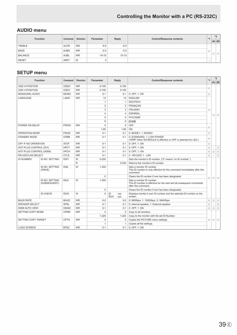
39 E
AUDIO menuFunction Command Direction Parameter Reply Control/Response contents *1
*2
(A) (B)
TREBLE AUTR WR -5-5 -5-5
○ ○ ○BASS AUBS WR -5-5 -5-5
BALANCE AUBL WR -10-10 -10-10
RESET ARST W 3 -
SETUP menuFunction Command Direction Parameter Reply Control/Response contents *1
*2(A) (B)
OSDH-POSITION OSDH WR 0-100 0-100 ○
○ ○
OSDV-POSITION OSDV WR 0-100 0-100MONAURALAUDIO MONO WR 0-1 0-1 0:OFF,1:ON ○LANGUAGE LANG WR 14 14 ENGLISH
○
1 1 DEUTSCH2 2 FRANÇAIS3 3 ITALIANO4 4 ESPAÑOL5 5 РУССКИЙ6 6
POWERONDELAY PWOD WR 0 0 OFF ○1-60 1-60 ON
OPERATIONMODE FNCM WR 0-1 0-1 0:MODE1,1:MODE2 ○STANDBYMODE STBM WR 0-1 0-1 0:STANDARD,1:LOWPOWER
(“ERR"whenSCHEDULEiseffectiveorOFFisselectedforLED.) ○OFFIFNOOPERATION ATOF WR 0-1 0-1 0:OFF,1:ON ○HOTPLUGCONTROL(DVI) HPCT WR 0-1 0-1 0:OFF,1:ON ○ - ○HOTPLUGCONTROL(HDMI) HPCH WR 0-1 0-1 0:OFF,1:ON ○ ○ ○RS-232C/LANSELECT CTLS WR 0-1 0-1 0:RS-232C1:LAN ○ - ○IDNUMBER IDNO.SETTING IDST W 0-255 Setsthemonitor’sIDnumber.(“0”means“noIDnumber”.)
○ ○ ○
R 0-255 Returnsthemonitor’sIDnumber.IDNO.SETTING(ONCE)
IDSL W 1-255 SetsamonitorIDnumber.ThisIDnumberisonlyeffectiveforthecommandimmediatelyafterthiscommand.
0 ClearstheIDnumberifonehasbeendesignated.IDNO.SETTING(SUBSEQUENT)
IDLK W 1-255 SetsamonitorIDnumber.ThisIDnumberiseffectiveforthenextandallsubsequentcommandsafter this command.
0 ClearstheIDnumberifonehasbeendesignated.IDCHECK IDCK W 0 ID :xxx
IDLK :yyyDisplaysmonitor’sownIDnumberandtheselectedIDnumberonthescreen.
BAUDRATE BAUD WR 0-2 0-2 0:9600bps,1:19200bps,2:38400bps ○ ○ ○SPEAKERSELECT SPSL WR 0-1 0-1 0:Internalspeaker,1:Externalspeaker ○ - ○HDMIAUTOVIEW HDAW WR 0-1 0-1 0:OFF,1:ON ○ ○ ○SETTINGCOPYMODE CPMD WR 0 0 Copytoallmonitors.
○ ○ ○1-225 1-225 CopytothemonitorwiththesetIDNumber.
SETTINGCOPYTARGET CPTG WR 0 0 CopiesthePICTUREmenusettings.1 1 Copiesallthesettings.
LOGOSCREEN BTSC WR 0-1 0-1 0:OFF,1:ON
Controlling the Monitor with a PC (RS-232C)

40E
Controlling the Monitor with a PC (RS-232C)
OPTION menuFunction Command Direction Parameter Reply Control/Response contents *1
*2(A) (B)
DATE/TIMESETTING DATE WR AABBCCDDEE AABBCCDDEE AA:Year,BB:Month,CC:Day,DD:Time,EE:Minute
○ ○ ○
DATEDISPLAYFORMAT DTFT WR 0-2 0-2 0:YYYY/MM/DD,1:MM/DD/YYYY,2:DD/MM/YYYYYYYY:Year,MM:Month,DD:Day
TIMEDISPLAYFORMAT TMFT WR 0-1 0-1 0:24-HOURTIME,1:12-HOURTIME
SCHEDULE SC01-SC08
WR ABCDEFFGGH ABCDEFFGGH ScheduleofaspecifiednumberA:Schedule 0=Noteffective,1=EffectiveB:Power 0=OFF,1=ONC:Dayoftheweek1 0=Onlyonce,1=Everyweek,2=EverydayD:Dayoftheweek2 0=Sunday,1=Mondaythrough6=Saturday, 9=NotexistE:Dayoftheweek3 0=Sunday,1=Mondaythrough6=Saturday, 9=NotexistF:Time 00-23G:Minute 00-59H:Input 0=Notspecified,1=PCDVI-D/AVDVI-D,
2=PCD-SUB,3=PCRGB/AVCOMPONENT,4=AVVIDEO,5=AVS-VIDEO, 6=PCHDMI/AVHDMI
“ERR”whenLOWPOWERisselectedforSTANDBYMODE.SCHEDULEBRIGHTNESS SB01-
SB08WR 0-31 0-31 Screen brightness to change
99 99 DisablebrightnesssettingINPUTSELECT DVI DVSL WR 0-1 0-1 0:PCDVI-D,1:AVDVI-D ○ -
○
BNC BNSL WR 0-1 0-1 0:PCRGB,1:AVCOMPONENT ○ -D-SUB SLDS WR 0-2 0-2 0:PCD-SUB,1:AVCOMPONENT,2:AVVIDEO ○ ○HDMI HDSL WR 0-1 0-1 0:PCHDMI,1:AVHDMI ○ ○
AUDIOSELECT PCDVI-D ASDP WR 1-3 1-3 1:AUDIO(STEREOMINI),2:AUDIO1(RCA),3:AUDIO2(RCA)
○
-PCHDMI ASHP WR 0-1 0-1 0:HDMI,1:AUDIO(STEREOMINI) ○
2-3 2-3 2:AUDIO1(RCA),3:AUDIO2(RCA) -PCD-SUB ASAP WR 1-3 1-3 1:AUDIO(STEREOMINI) ○
2:AUDIO1(RCA),3:AUDIO2(RCA) -PCRGB ASCP WR 1-3 1-3 1:AUDIO(STEREOMINI),2:AUDIO1(RCA),3:AUDIO2(RCA) -AVDVI-D ASDA WR 1-3 1-3 1:AUDIO(STEREOMINI),2:AUDIO1(RCA),3:AUDIO2(RCA) -AVHDMI ASHA WR 0-1 0-1 0:HDMI,1:AUDIO(STEREOMINI) ○
2-3 2-3 2:AUDIO1(RCA),3:AUDIO2(RCA) -AVCOMPONENT(BNC)
ASCA WR 1-3 1-3 1:AUDIO(STEREOMINI),2:AUDIO1(RCA),3:AUDIO2(RCA)-
AVCOMPONENT(D-SUB)
ASC2 WR 1-3 1-3 1:AUDIO(STEREOMINI),2:AUDIO1(RCA),3:AUDIO2(RCA) ○AVS-VIDEO ASSA WR 1-3 1-3 1:AUDIO(STEREOMINI),2:AUDIO1(RCA),3:AUDIO2(RCA) -AVVIDEO(BNC) ASVA WR 1-3 1-3 1:AUDIO(STEREOMINI),2:AUDIO1(RCA),3:AUDIO2(RCA) -AVVIDEO(D-SUB) ASV2 WR 1-3 1-3 1:AUDIO(STEREOMINI),2:AUDIO1(RCA),3:AUDIO2(RCA) ○
INPUT RESOLUTION(PC)
RESOLUTIONCHECK PXCK R - Returns current resolution in the form of hhh, vvv.
-
○ ○
PIXELSETTING(PCD-SUB,PCRGB)
PXSL WR 1 1 768)1360x7682 2 768)1280x7683 3 768)1024x7685 5 480)848x4806 6 480)640x4807 7 1050)1680x10508 8 1050)1400x10509 9 768)AUTO10 10 480)AUTO
INPUTRESOLUTION(AV) RESOLUTIONCHECK RESO R - 480i,480p,1080i,720p,1080p,VGA,etc. -ZOOM2SPECIALSETTING (PCD-SUB,PCRGB)
Z2SP WR 0-1 0-1 0:OFF,1:ON ○SCANMODE SCAN WR 0-2 0-2 0:MODE1,1:MODE2,2:MODE3(WhentheinputmodeisAV) ○POWERMANAGEMENT(PC) PMNG WR 0-1 0-1 0:OFF,1:ON ○POWERMANAGEMENT(AV) PMAV WR 0-1 0-1 0:OFF,1:ON ○COLORSYSTEM CSYS WR 0-5 0-5 0:AUTO,1:PAL,2:PAL-60,3:SECAM,4:NTSC3.58,5:NTSC4.43 ○ ○ ○AUDIOOUTPUT(RCA) AOUT WR 0-2 0-2 0:VARIABLE1,1:FIXED,2:VARIABLE2 ○
○ ○AUDIOLEVEL(STEREOMINI) AIVP WR 0-1 0-1 0:1.0Vrms,1:0.5Vrms ○SELFADJUST AADJ WR 0-1 0-1 0:OFF,1:ON ○AUTOINPUTCHANGE AINC WR 0-1 0-1 0:OFF,1:ON ○TOUCHPANELMODE GMDP WR 0-1 0-1 0:OFF,1:ON(WhentheinputmodeisPC) ○

41 E
PIP/PbyP menuFunction Command Direction Parameter Reply Control/Response contents *1
*2(A) (B)
PIPMODES MWIN WR 0-3 0-3 0:OFF,1:PIP,2:PbyP,3:PbyP2 ○
○ ○
PIPSIZE MPSZ WR 1-64 1-64 ○PIP POS THELONGEST
DIRECTIONMHPS W 0-100 ○
R 0-100 ○THESHORTESTDIRECTION
MVPS W 0-100 ○R 0-100 ○
PIPPOSLD+SDBATCH MPOS W 0-100,0-100 Specify the position in MPOSxxxyyy format. (xxx:Longerside,yyy:Shortersideposition) ○
R 0-100,0-100 Returnsaresponsein(xxx,yyy)format.(xxx:Longerside,yyy:Shortersideposition) ○
PIPBLEND MWBL WR 0-15 0-15 ○PIPSOURCE MWIP WR 1 1 PCDVI-D
○
- ○2 2 PCD-SUB ○ ○3 3 AVCOMPONENT(BNC)/AVCOMPONENT(D-SUB) ○ ○4 4 AVVIDEO(BNC)/AVVIDEO(D-SUB) ○ ○6 6 PCRGB - ○7 7 AVDVI-D - ○8 8 AVS-VIDEO - ○9 9 AVHDMI ○ ○10 10 PCHDMI ○ ○
SOUNDCHANGE MWAD WR 1-2 1-2 1:MAIN,2:SUB ○○ ○MAINPOS(Mainscreen) MWPP WR 0-1 0-1 0:POS1,1:POS2 ○
PbyP2POS(Subscreen) MW2P WR 0-2 0-2 0:POS1,1:POS2,2:POS3 ○AUTOOFF MOFF WR 0-1 0-1 0:MANUAL,1:AUTO ○
Initialization/Functional Restriction Setting (FUNCTION) menuFunction Command Direction Parameter Reply Control/Response contents *1
*2(A) (B)
ALLRESET RSET W 0 0:ALLRESET - ○ -0-1 0:ALLRESET1,1:ALLRESET2 - - ○
ADJUSTMENTLOCK ALCK WR 0-2 0-2 0:OFF,1:ON1,2:ON2 ○
○ ○
ADJUSTMENTLOCKTARGET ALTG WR 0-2 0-2 0:REMOTECONTROL,1:MONITORBUTTONS,2:BOTH ○OSDDISPLAY LOSD WR 0-2 0-2 0:ON1,1:OFF,2:ON2 ○LED OFLD WR 0-1 0-1 0:ON,1:OFF
“ERR”whenLOWPOWERisselectedforSTANDBYMODE. ○TEMPERATUREALERT TALT WR 0-2 0-2 0:OFF,1:OSD&LED,2:LED ○STATUSALERT SALT WR 0-2 0-2 0:OFF,1:OSD&LED,2:LED ○POWERBUTTON PBTN WR 0-1 0-1 0:MONITOR,1:CONTROLLER ○CONTROLLERINPUT PCIP WR 0-2 0-2 0:D-SUB,1:HDMI(“ERR”whenMONITORisselectedforPOWER
BUTTON.) ○ ○ ○2:DVI-D(“ERR”whenMONITORisselectedforPOWERBUTTON.) ○ - ○
Controlling the Monitor with a PC (RS-232C)
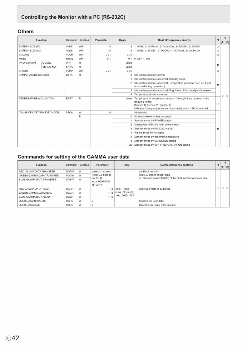
42E
OthersFunction Command Direction Parameter Reply Control/Response contents *1
*2
(A) (B)SCREENSIZE(PC) WIDE WR 1-5 1-5 1:WIDE,2:NORMAL,3:DotbyDot,4:ZOOM1,5:ZOOM2 ○
○ ○
SCREENSIZE(AV) WIDE WR 1-5 1-5 1:WIDE,2:ZOOM1,3:ZOOM2,4:NORMAL,5:DotbyDot ○VOLUME VOLM WR 0-31 0-31 ○MUTE MUTE WR 0-1 0-1 0:OFF,1:ON -INFORMATION MODEL INF1 R Value ●
SERIALNO SRNO R ValueBRIGHT VLMP WR 0-31 0-31 ○TEMPERATURESENSOR DSTA R 0 Internal temperature normal
●1 Internaltemperatureabnormal(Standbymode)2 Internaltemperatureabnormal(Temperatureisnormalnow,butitwas
abnormalduringoperation.)3 Internaltemperatureabnormal(Brightnessofthebacklightdecreases.)4 Temperature sensor abnormal
TEMPERATUREACQUISITION ERRT R Value Temperatureattemperaturesensors1through3arereturnedinthefollowing forms:[Sensor1],[Sensor2],[Sensor3]Indicatesatemperaturesensorabnormalitywhen“126”isreturned.
○
CAUSEOFLASTSTANDBYMODE STCA W 0 Initialization
●
R 0 No detectable error has occurred1 StandbymodebyPOWERbutton2 Main power off by the main power switch3 StandbymodebyRS-232CorLAN4 WaitingmodebyNoSignal6 Standby mode by abnormal temperature8 StandbymodebySCHEDULEsetting20 StandbymodebyOFFIFNOOPERATIONsetting
Commands for setting of the GAMMA user dataFunction Command Direction Parameter Reply Control/Response contents *1
*2
(A) (B)REDGAMMADATATRANSFER UGRW W aaxxxx ··· xxxxcc
(xxxx:32pieces)aa:01-16xxxx:0000-1023cc:00-FF
aa:Blocknumberxxxx:32piecesofuserdatacc:Checksum(ASCIIdata)oftheblocknumberanduserdata
○ ○ ○
GREENGAMMADATATRANSFER UGGW WBLUEGAMMADATATRANSFER UGBW W
REDGAMMADATAREAD UGRR W 1-16 xxxx ··· xxxx(xxxx:32pieces)xxxx:0000-1023
xxxx:Userdataof32piecesGREENGAMMADATAREAD UGGR W 1-16BLUEGAMMADATAREAD UGBR W 1-16USERDATAINITIALIZE UGRS W 0 Initializetheuserdata.USERDATASAVE UGSV W 0 Save the user data in the monitor.
Controlling the Monitor with a PC (RS-232C)

43 E
WhenthePN-ZB01(optional)isattached,yourmonitorcanbeconnectedtoaLANallowingyoutocontrolitfromaPConthe LAN. Youcanalsoconfigurethemonitortosende-mailnotificationwhen it has a problem. TheconnectionrequiresacommerciallyavailableLANcable(UTPcable,Category5,straightthrough).
HubLAN terminal
LAN cable (commercially available, straight)
Network (LAN)
TIPS
• YoumustassignanIPaddresstothemonitorbyfollowingtheproceduresin“SettingstoconnecttoaLAN”.(Seethedescriptionontheright.)
• YourPCmustbeinstalledwithInternetExplorer(version7.0orlater).
• TocontrolthemonitorviaLAN,setRS-232C/LANSELECTtoLAN.(Seepage26.)
• YoucannotuseRS-232CandLANcontrolsimultaneously.
Initializing personal information• WhenthePN-ZB01(optional)isattached,personalinformationsuchase-mailaddressescanberegisteredinthemonitor.Beforetransferringordisposingofthemonitor,initializeallsettingsbyselectingALLRESET1.(Seepage31.)NotethatALLRESET2willnotinitializee-mailaddresses and other settings.
Controlling the Monitor with a PC (LAN)Settings to connect to a LANSet the monitor’s IP address and subnet mask to match the settings of your LAN. ThesesettingscanbemadeoneitherthemonitororaPCconnected to the monitor.ThesettingsdependontheconfigurationofyourLAN.Askyour LAN administrator for details.
■ To set on the monitorSetRS-232C/LANSELECTontheSETUPmenutoLAN,andthensettheLANSETUPoptions.(Seepage26.)Aftersettingeachitem,selectSETandpressMENU .
DHCP CLIENTIfyourLANhasaDHCPserverandyouwishtoobtainanaddress automatically, change this setting to ON. Tosettheaddressmanually,setthistoOFF.IP ADDRESSIftheDHCPCLIENTissettoOFF,specifyanIPaddress.Press or to select items, and press or to change the values.SUBNET MASKIftheDHCPCLIENTissettoOFF,specifythesubnetmask.Press or to select items, and press or to change the values.DEFAULT GATEWAYIftheDHCPCLIENTissettoOFF,specifythedefaultgateway. Ifyouarenotusingagateway,specify“0.0.0.0”.Press or to select items, and press or to change the values.RESETResets the values of the LAN settings to the factory preset values. Select ON and then press MENU .
TIPS
• WhentheIPaddressissetmanually,theIPaddressesofthemonitorconnectedtotheRS-232Coutputterminal and the daisy chain of connected monitors that follows can be assignedautomatically.(Seepage26.)

44E
■ To set from a PCWhenthemonitorisconnectedtoaPC,LANsettingscanbeconfiguredviaPC.
Set up process(1)ConnectyourmonitortoaPC(2)SpecifythePC’sIPaddress(3)Configurethemonitor’sLANsettings
(1) Connecting your monitor to a PCConnectacommerciallyavailablecrossoverLANcable(UPTcable,Category5)totheLANportonthePCandthismonitor.
LAN cable (commercially available, crossover)
To LAN terminal
PC
LAN terminal
(2) Specifying the PC’s IP addressToconfigurethemonitor’sLANsettings,youmusttemporarilychangethesettingsonthePC.ThisexplanationisbasedonWindows7.1. LogontothePCwithanadministratoraccount.2.Click[Start],andthenclick“ControlPanel”.3.Click“Viewnetworkstatusandtasks”in“Networkand
Internet”.In“ClassicView”,click“NetworkandSharingCenter”.
4.Click“LocalAreaConnection”andthen“Properties”.5.Click“InternetProtocolVersion4(TCP/IPv4)”andthen
“Properties”.6. Make a note of the current IP address, subnet mask, and
default gateway settings. Make sure you write this information now as you will be changing the IP address, subnet mask, and default gateway settings back to these settings afterwards.
7. TemporarilychangetheIPaddressandsubnetmask.To access the monitor as it is shipped from the factory, set as follows. • IPAddress:192.168.150.1• SubnetMask:255.255.255.0• DefaultGateway:(leaveblank)
8.Click[OK]andthenrebootthePC.
TIPS
• Thismonitorisfactorypresetasshownbelow. (WhenDHCPCLIENTissettoOFF)
IPAddress :192.168.150.2 SubnetMask :255.255.255.0 DefaultGateway :0.0.0.0
(3) Configuring the monitor’s LAN settingsAccessthemonitorusingInternetExplorer.
Controllingthemonitor1. TurnthepowerONtothemonitor.2.SetRS-232C/LANSELECTontheSETUPmenutoLAN.3.SetDHCPCLIENTtoOFFinLANSETUPontheSETUP
menu.
PCoperation4. LaunchInternetExplorer,inthe“Address”boxtype
“http://192.168.150.2/”andpresstheEnterkey.
You will be prompted to enter a user name and password. 5. Leavetheusernameandpasswordboxesblankandclick
[OK].
Controlling the Monitor with a PC (LAN)

45 E
6. Click on “LAN SETUP” under NETWORK.
7. Specify the “DHCP CLIENT”, “IP ADDRESS”,etc.
DHCP CLIENTIf your LAN has a DHCP server and you wish to obtain an address automatically, change this setting to “ON”. To set the address manually, set this to “OFF”. IP ADDRESSIf the DHCP CLIENT is set to “OFF”, specify an IP address.SUBNET MASKIf the DHCP CLIENT is set to “OFF”, specify the subnet mask.DEFAULT GATEWAYIf the DHCP CLIENT is set to “OFF”, specify the default gateway. If you are not using a default gateway, specify “0.0.0.0”.
8. When the setting is changed, click [Apply].9. Check the message and click [OK].10. Exit Internet Explorer. 11. Restore the PC’s IP address jotted in Step 6, “(2)
Specifying the PC’s IP address”. 12. Connect the monitor and the PC to the LAN.
Caution
• Wait10secondsafterclicking[OK]beforeproceeding.• Whenoperatingusingtheremotecontrolunitorsimilar,
click [Refresh].
TIPS
• WhentheIPaddressissetmanually,theIPaddressesofthe monitor connected to the RS-232C output terminal and the daisy chain of connected monitors that follows can be assigned automatically. (See page 26.)
Controlling with a PC■ Basic operationYou use Internet Explorer on a PC on the LAN to control the monitor.1. Launch Internet Explorer on the PC.2. In the “Address” box, type “http://” followed by your monitor’s
IP address followed by “/”, then press the Enter key. YoucanconfirmtheIPaddresswiththeDISPLAYfunction.
When prompted to enter a user name and password, type theusernameandpasswordthatyouspecifiedinthesecurity settings (see page 47), and click [OK].If you did not make any security settings, leave the spaces blank and click on [OK].
3. You can check, control, and change the monitor’s status and settings by clicking the menu items on the left side of the screen.
• Ifyouseean[Apply]buttonnexttoasetting,clickitafteryou change that setting.
TIPS
• Seepages46to50fordetailsoneachsetting.• Ifyouclick[Refresh]beforethescreenfinishesupdating
the current display, the “Server Busy Error” will appear. Wait for a moment before operating your monitor again.
• Youcannotoperatethemonitorwhileitiswarmingup.• If“DHCPCLIENT”issetto“ON”,pressDISPLAY on the
remote control unit two times and then check the monitor’s IP address.
Controlling the Monitor with a PC (LAN)

46E
■ INFORMATIONInformation about this monitor appears.
■ CONTROLYou can control the operations corresponding to the buttons (POWER INPUT SIZE ) on the remote control unit. (See page 21.)
TIPS
• Instandbymode,PowerONistheoperationavailable.
■ ADJUSTMENTYou can adjust these settings which are also available on the monitor’s menu. • SCREEN(Seepage24.)• PICTURE(Seepage24.)• PICTURE(ADVANCED)(Seepage30.)• AUDIO(Seepage25.)• SETUP(Seepage25.)• OPTION(Seepage26.)• SCHEDULE(Seepage29.)• PIP/PbyP(Seepage27.)• FUNCTION(Seepage31.)
TIPS
• AfterchangingDISPLAYCOLORPATTERNtoOFF,click[Refresh] to correctly retrieve the status of the monitor.
Controlling the Monitor with a PC (LAN)

47 E
■ NETWORK (LAN SETUP)This screen allows you to set the settings necessary when the monitor is connected to a LAN.
DHCP CLIENTIf your LAN has a DHCP server and you wish to obtain an address automatically, change this setting to “ON”. To set the address manually, set this to “OFF”. IP ADDRESSIf the DHCP CLIENT is set to “OFF”, specify an IP address.SUBNET MASKIf the DHCP CLIENT is set to “OFF”, specify the subnet mask.DEFAULT GATEWAYIf the DHCP CLIENT is set to “OFF”, specify the default gateway. If you are not using a default gateway, specify “0.0.0.0”.DNS SERVERSpecify the DNS server address. If you are not using a DNS server, specify “0.0.0.0”. RESETClicking [Execute] returns all of the LAN SETUP settings to the factory-preset values except for the DNS SERVER setting.
TIPS
• WhentheIPaddressissetmanually,theIPaddressesofthe monitor connected to the RS-232C output terminal and the daisy chain of connected monitors that follows can be assigned automatically. (See page 26.)
■ NETWORK (SECURITY)This screen allows you to specify the security-related settings.
USER NAME / PASSWORDSets up a user name and password to restrict access to this monitor. After entering a user name and password, click [Apply].ACCEPT IP ADDRESSYou can limit access to this monitor by registering IP addresses of PCs that should have access. Tolimitaccess,specifytheoption“FromonlyspecificIPaddresses”. Otherwise, to allow access from any PC, specify “All IP Addresses”.IP ADDRESS 1 to 3If“ACCEPTIPADDRESS”issetto“FromonlyspecificIPaddresses”, enter the IP addresses that you want to allow.
TIPS
• TheUSERNAMEandPASSWORDcanbeupto8alphanumeric characters or symbols.
• Tocanceltheusernameand/orpasswordafterithasbeenset, make the box empty and click [Apply].
Controlling the Monitor with a PC (LAN)

48E
■ NETWORK (GENERAL)This screen allows you to specify the general LAN settings.
MONITOR NAMESpecify a name for this monitor as it should appear on the Internet Explorer screen.AUTO LOGOUT TIMESpecify the time (in minutes) to elapse before automatically disconnecting this monitor from the network. Specify in minutes from 1 to 65535. A value of ‘0’ will disable this function. DATA PORTSpecify the TCP port number to use for exchanging data with the monitor. Specify a value from 1025 to 65535.SEARCH PORTSpecify the port number to use when searching for this monitor. Specify a value from 1025 to 65535.INSTALLATION INFORMATION (NAME/LOCATION)Specify the information to display for this monitor in the Internet Explorer window.
TIPS
• TheMONITORNAMEcanbeupto16alphanumericcharacters or symbols.
• Enterupto50charactersintheNAMEfieldintheINSTALLATIONINFORMATION.
• Enterupto100charactersintheLOCATIONfieldintheINSTALLATIONINFORMATION.
■ MAIL (ORIGINATOR) Thisscreenallowsyoutoconfigurethee-mailsentperiodicallyor when the monitor has an error.ThesettingsdependontheconfigurationofyourLAN.Askyour LAN administrator for details.
SMTP SERVERSpecifytheSMTPserveraddressforsendinge-mail.* When using a domain name, make sure to specify the
DNS SERVER as well. (See page 47.)ORIGINATOR E-MAIL ADDRESSSpecify the e-mail address for this monitor. This address becomes the e-mail address of the originator. ORIGINATOR NAMESpecify the name for the originator. Thisnameappearsinthe“OriginatorName”fieldofthee-mail.AUTHENTICATIONSpecify the authentication method to use when sending e-mail. POP SERVERIfthe“AUTHENTICATION”methodis“POPbeforeSMTP”,specify the POP server address. ACCOUNT NAME / PASSWORDIfthe“AUTHENTICATION”methodis“POPbeforeSMTP”,specify the account name and password to connect to the POP server.
TIPS
• Youcanenterupto64alphanumericcharactersorsymbolsfortheORIGINATORE-MAILADDRESS,ORIGINATORNAME,ACCOUNTNAME,andPASSWORD.
• TheSMTPSERVERandPOPSERVERcanbeupto64characters. The following characters can be used: a-z, A-Z, 0-9, - , .
Controlling the Monitor with a PC (LAN)

49 E
■ MAIL (RECIPIENT) This screen allows you to specify the recipients of the e-mail sent periodically or when the monitor has an error.
RECIPIENT E-MAIL ADDRESSESSpecify the e-mail addresses to send error notification e-mail to.CONDITIONSpecify the conditions to send mails. When you check PERIODICAL, specify the date and time to send the mails in the PERIODICAL setting.CONFIRMATIONSends test e-mail.This allows you to confirm that the e-mail settings are configured properly.Attach the log file to a TEMPERATURE/HARDWARE error e-mail.When this option is checked, a log is added to the mail which notifies a temperature or status error.
TIPS
• The RECIPIENT E-MAIL ADDRESSES can be up to 64 alphanumeric characters or symbols.
Controlling the Monitor with a PC (LAN)
■ MAIL (PERIODICAL)When PERIODICAL for CONDITION of MAIL (RECIPIENT) is checked, set the date and time to send the mail.
DAY OF THE WEEKSpecify the day of the week to send the periodical mails.TIMESpecify the time of the day to send the periodical mails.
Caution
• Do not turn off the main power when you set to send the periodical mails.
• Specify the correct date and time. (See page 26.) If the date and time settings are incorrect, the periodical mail is not sent properly.
• Regularly confirm that the specified date and time is correct.
• When LOW POWER is selected for STANDBY MODE, periodical mails will not be sent in standby mode.

50E
Controlling the Monitor with a PC (LAN)
■ SNMPYoucanconfiguresettingsrelatedtoSNMP.
SNMP SETTINGSetwhethertoenableordisableSNMP.VERSIONSettheversionoftheSNMPtobesupported.COMMUNITY NAME 1 to 3Set the name of the community required for the access.USER 1 to 3Set the user name, password, authentication method and other options required for access.TRAP SETTINGSet whether to enable or disable the trap function.When this function is enabled, a trap will be sent when the monitor is turned on.TRAP SETTING OF AUTHENTICATION ERRORSetwhetherthetrapfunctionsendsanotificationwhenauthentication fails.TRAP ADDRESS & PORTSet the destination address and port number of the notificationsentbythetrapfunction.
Caution
• AfteryousetSNMP,click[Switchthemainpowerofmonitor off and on now.] or turn off the monitor and then turn it on again with the main power switch. When the monitor restarts, wait about 30 seconds and then start the next operation.
• IftheIPaddressischangedwhiletheSNMPfunctionisoperational, turn off the monitor and then turn it on again with the main power switch.
TIPS
• DependingontheSNMPsettings,ashortdelaymayoccurbeforetheSNMPisusable.(About2minutes)
• Upto16alphanumericlettersandsymbolscanbeusedforthe community name, user name and password.
■ SERVICE & SUPPORT (URL INFORMATION)
YoucandisplayaspecificURLintheURLINFORMATIONfieldontheINFORMATIONscreenwhenanerroroccursinthe monitor. (See page 46.)
URL INFORMATIONEntertheURLtodisplayontheINFORMATIONscreenwhenan error occurs on the monitor.Up to 64 alphanumeric characters or symbols can be used.CONDITIONSpecify the condition to display the URL.CONFIRMATIONThehomepageofthespecifiedURLisdisplayed.You can check whether the URL you entered is correct.
TIPS
• Itisalsopossibletospecifythemessagetext,suchasthename of a contact or a telephone number, to be displayed instead of the linked URL.

51 E
TroubleshootingIf you are experiencing any problem with your display, before calling for service, please review the following troubleshooting tips.
There is no picture or sound.• Isthepowercorddisconnected?(Seepage14.)• Isthemainpowerswitchoff?(Seepage16.)• Isthemonitorinstandbymode(thepowerLEDilluminatinginorange)?(Seepage16.)
• Makesurecorrectinputmodeisselected.(Seepage21.)• Ifanyexternalequipmentisconnected,makesuretheequipmentisoperating(playingback).
Remote control does not work.• Arethebatteriesinsertedwithpolarity(+,-)aligned?(Seepage15.)
• Arethebatteriesexhausted?• Pointtheremotecontrolunittowardthemonitor’sremotecontrolsensor.(Seepage15.)
• Isthemenudisplayhiddenorisoperationdisabled?(Seepage31.)
Sound from left and right speakers is reversed.Sound is heard from only one side.• Areaudiocablesconnectedproperly?(Seepages12to13.)
• Makesureaudiocablesforexternalspeakersareconnected properly: left and right cables may be reversed oroneofthetwocablesmaynotbeconnected.(Seepage13.)
• CheckthesettingofBALANCEforAUDIOmenu.(Seepage25.)
There is a picture but no sound.• Isthesoundmuted?• Makesurethevolumeisnotsettominimum.• Areaudiocablesconnectedproperly?• IsthesettingofAUDIOSELECTontheOPTIONmenucorrect?(Seepage26.)
• IsthesettingofSPEAKERSELECTontheSETUPmenucorrect?(Seepage26.)
Unstable video.• Thesignalmaybeincompatible.• TrytheautomaticscreenadjustmentwhenthePCD-subinputterminalorPCRGBinputterminalsareused.
• Ifthetopandbottomoftheimagearenothorizontallyaligned,setTOUCHPANELMODEontheOPTIONmenutoOFF.
The video from the PC/AV HDMI input terminal does not appear properly.• IsthesettingforHDMIofINPUTSELECTontheOPTIONmenucorrect?(Seepage26.)
• IstheHDMIcableHDMIstandardcompliant?Themonitorwill not work with cables that are not standard compliant.
• Istheinputsignalcompatiblewiththismonitor?(Seepage55.)
The video from the PC/AV DVI-D input terminal does not appear properly.• IsthesettingforDVIofINPUTSELECTontheOPTIONmenucorrect?(Seepage26.)
• Istheinputsignalcompatiblewiththismonitor?(Seepage55.)
• Turnoffthepowertotheconnectedequipmentandthenturn the power on again.
• Ifthemonitorsareconnectedinadaisychain,turnoffthepower to all the monitors connected in a daisy chain and then turn the power on again.
The video from PC D-SUB, PC RGB, AV COMPONENT, or AV VIDEO does not appear correctly.• IsthesettingforBNCorD-SUBofINPUTSELECTontheOPTIONmenucorrect?(Seepage26.)
• Istheinputsignalcompatiblewiththismonitor?(Seepage55.)
Control buttons do not work.There is no picture.• Loadnoisesfromoutsidemaybeinterferingwithnormal
operation. Turn off the power and turn it on after waiting at least5seconds,andthenchecktheoperation.
The input mode changes automatically.• WhentheAUTOINPUTCHANGEisONandnosignal
is present in a selected input mode, the AUTO INPUT CHANGEautomaticallychangestheselectedmodetoamode where a video signal is present.
The input mode may change in the following cases:-Whenacomputerisinstandbymode.-Whenvideoplayisstoppedwithaplaybackdevice.
The touch panel does not respond.• IstheUSBcableconnectedproperly?(TouchPanelDriverOperationManual)
• Hasthetouchpaneldriverbeeninstalled?(TouchPanelDriverOperationManual)
• Hasthepentipofthetouchpenbecomeworn?Replacethepentip.(Seepage20.)
• Isthebatteryinsertedinthewrongorientation(+,-)inthetouchpen?(Seepage18.)
• Isthetouchpenbatteryexhausted?
The response of the touch screen is slow.Some parts of the screen do not respond.• Isthescreenexposedtodirectsunlightorotherstrong
light? The touch panel uses infrared rays and thus may not operate correctly.
• Isthereanobstaclebetweentheinfraredtransmitter/receiverandthetouchpenoryourfinger?Anobstaclewillpreventcorrectoperation.Ifyourfingersorasleeveare too close to the screen, correct operation will not be possible.
• Istheinfraredtransmitter/receiverdirty?Gentlywipeoffany dirt with a soft cloth.
• Ifthetouchpanelistouchedwithasmalltiplessthanabout3/16inch(4mm)x3/16inch(4mm),thetouchmaynotbe detected by infrared and correct operation will not take place.
• WhenstartingyourcomputerorconnectingtheUSBcable,do not touch the touch panel. If you touch the touch panel, this may be detected as an element failure in the infrared transmitter/receiver and incorrect operation will result.
Power LED flashes red.“STATUS [xxxx]” appears in the corner of the screen.• Hardwarehasaproblem.Turnoffthemonitorandrequest
repair from your SHARP dealer. (WhenSTATUSALERTissettoOSD&LED.Thisvariesdependingonthesetting.)
The touch panel power LED lights red.• Hardwarehasaproblem.Turnoffthemonitorandrequest
repair from your SHARP dealer.

52E
When “AUTO DIMMING” is displayed.• Whentheinternaltemperatureofthemonitorrises
excessively, the brightness of the backlight automatically decreases in order to prevent a further temperature rise. If you attempt to use toadjustthebrightnesswhilethemonitorisinthisstate,“AUTODIMMING”isdisplayedand you cannot change the brightness.
• Removethecauseoftheexcessivetemperaturerise.
The monitor makes a cracking sound.• Youmayoccasionallyhearacrackingsoundfromthe
monitor. This happens when the cabinet slightly expands and contracts according to change in temperature. This does not affect the monitor’s performance.
The Power LED is flashing in red and green alternately. When “TEMPERATURE” is displayed in the corner of the screen.• Whentheinternaltemperatureofthemonitorrises
excessively, the brightness of the backlight decreases automaticallyinordertopreventhigh-temperature-relatedproblems.Whenthisoccurs,“TEMPERATURE”isdisplayedonthescreenandthePowerLEDflashesredandgreenalternately.(WhenTEMPERATUREALERTissettoOSD&LED.Thisvariesdependingonthesetting.)
• Iftheinternaltemperaturerisesfurther,themonitorautomaticallyentersstandbymode.(ThePowerLEDcontinuesflashingredandgreenalternately.)
• Removethecauseoftheexcessivetemperaturerise.-Ifthemonitorentersstandbymodeduetoarisein
temperature, to return to normal display, turn the power switch off and then back on again. The monitor, however, will enter standby mode again if the cause of the temperatureriseisnoteliminated.(Seepage8.)
-Checkwhetherthemonitorisplacedatalocationwhereaquickriseintemperatureislikely.Internaltemperaturerisesquicklyiftheventsonthemonitorareblocked.
-Internaltemperaturerisesquicklyifdustaccumulatesinside the monitor or around the vents. Remove dust if possible. Ask SHARP dealer about removing internal dust.
Troubleshooting

53 E
Specifications nProduct SpecificationsModel PN-L702BLCDcomponent 70"Class[69-1/2inch(176.6cm)diagonal]TFTLCDMax. resolution (pixels) 1920x1080Max. colors Approx.1.06billioncolorsPixel pitch 0.802mm(H)×0.802mm(V)Viewingangle 160°right/left/up/down(contrastratio≥10)Screen active area inch(mm) 60-9/16 x 34-1/16 (1538.9x865.6)Computerinputsignal Digital(DVI1.0standard-compliant),AnalogRGB(0.7Vp-p)[75Ω]Sync signal Horizontal/verticalseparate(TTL:positive/negative),Sync-on-green,
Compositesync(TTL:positive/negative)Videocolorsystem NTSC(3.58MHz)/NTSC(4.43MHz)/PAL/PAL-60/SECAMPlug and play VESADDC2BPower management VESADPMS,DVIDMPMInput terminals PC/AV Digital HDMIx1
PC Analog MiniD-sub15pin,3rowsx1Audio 3.5mmministereojackx1Serial(RS-232C) D-sub9pinx1
WhenPN-ZB01(optional)isattached
PC/AV Digital DVI-D24pin(HDCPcompatible)x1PC Analog BNC*1*2x1AV Compositevideo BNCx1
S-video x1Component BNC(Y,Cb/Pb,Cr/Pr)*1x1
Audio RCApin(L/R)x2Output terminals Audio RCApin(L/R)x1
Serial(RS-232C) D-sub9pinx1WhenPN-ZB01(optional)isattached
PC/AV Digital DVI-D24pinx1Externalspeaker 7W+7W[6Ω]
LAN terminal [WhenPN-ZB01(optional)isattached]
10BASE-T/100BASE-TX
Speaker output 7W+7WTouch Panel Detectionmethod Infrared blocking detection method
Detectionarea inch(mm) 60-9/16 x 34-1/16 (1538.9x865.6)PCconnector USB(1.1compliant)Power supply SuppliedfromUSBTouch pen Ultrasonic communication method
Powerrequirement AC100V-240V,2.8A,50/60HzOperating temperature *3*4 41°Fto95°F(5°Cto35°C)Operating humidity*4 20%to80%(nocondensation)Power consumption(Maximum/inputsignalwaitingmode*5 / standby mode *6)
235W/1.0W/1.0W
Power consumption[WhenPN-ZB01(optional)isattached]
240W
Dimensions(excludingprotrusions) inch(mm) Approx. 64-7/8(W)x4-9/16(D)x38-11/16(H)(1,648x116x982)Weight lbs.(kg) Approx. 154.3(70)Weight[PN-ZB01(optional)] lbs.(kg) Approx.1.102(0.5)
*1 Cannotbeusedsimultaneously.*2 Doesnotsupportplugandplay.*3 TemperatureconditionmaychangewhenusingthemonitortogetherwiththeoptionalequipmentsrecommendedbySHARP.
Insuchcases,pleasecheckthetemperatureconditionspecifiedbytheoptionalequipments.*4 Inaddition,checktherequirementsofthecomputerandotherdevicestobeconnected,andmakesurethatallrequirementsaresatisfied.*5 WhenAUTOINPUTCHANGEissettoOFF.*6 WhenSTANDBYMODEissettoSTANDARD.WhenSTANDBYMODEissettoLOWPOWER:0.5WAsapartofourpolicyofcontinuousimprovement,SHARPreservestherighttomakedesignandspecificationchangesforproductimprovementwithoutpriornotice.Theperformancespecificationfiguresindicatedarenominalvaluesofproductionunits.Theremaybesomedeviationsfromthese values in individual units.
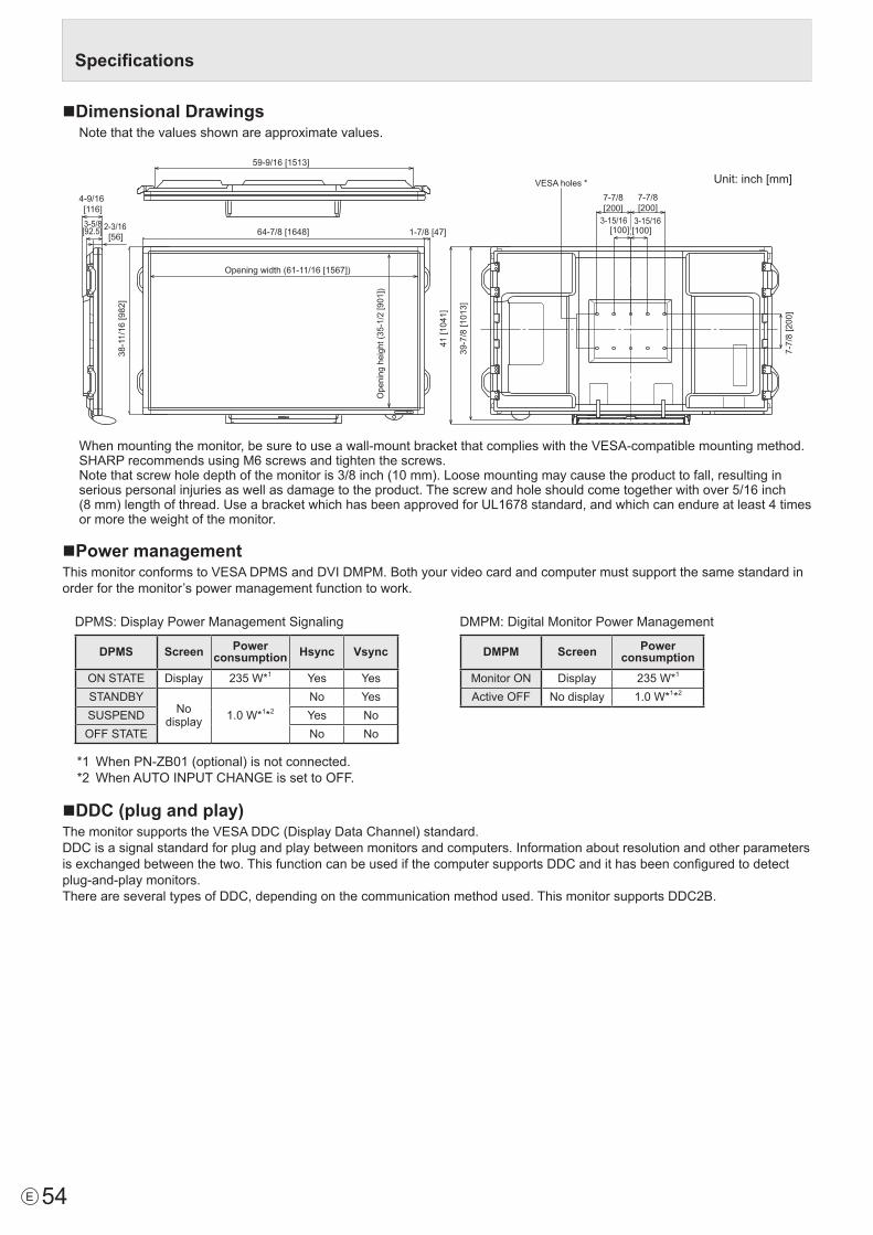
54E
Specifications
nDimensional DrawingsNote that the values shown are approximate values.
4-9/16 [116]
Unit: inch [mm] 7-7/8 [200]
7-7/8 [200]
3-15/16 [100]
3-15/16[100]
7-7
/8 [2
00]
VESA holes *
59-9/16 [1513]
Opening width (61-11/16 [1567])
Ope
ning
hei
ght (
35-1
/2 [9
01])
64-7/8 [1648] 1-7/8 [47]
38-1
1/16
[982
]
39-7
/8 [1
013]
41 [1
041]
2-3/16 [56]
3-5/8[92.5]
Whenmountingthemonitor,besuretouseawall-mountbracketthatcomplieswiththeVESA-compatiblemountingmethod.SHARP recommends using M6 screws and tighten the screws. Notethatscrewholedepthofthemonitoris3/8inch(10mm).Loosemountingmaycausetheproducttofall,resultinginseriouspersonalinjuriesaswellasdamagetotheproduct.Thescrewandholeshouldcometogetherwithover5/16inch (8mm)lengthofthread.UseabracketwhichhasbeenapprovedforUL1678standard,andwhichcanendureatleast4timesor more the weight of the monitor.
nPower managementThismonitorconformstoVESADPMSandDVIDMPM.Bothyourvideocardandcomputermustsupportthesamestandardinorder for the monitor’s power management function to work.
DPMS:DisplayPowerManagementSignaling
DPMS Screen Power consumption Hsync Vsync
ONSTATE Display 235W*1 Yes YesSTANDBY
Nodisplay 1.0W*1*2
No YesSUSPEND Yes NoOFFSTATE No No
*1 WhenPN-ZB01(optional)isnotconnected.*2 WhenAUTOINPUTCHANGEissettoOFF.
DMPM:DigitalMonitorPowerManagement
DMPM Screen Power consumption
Monitor ON Display 235W*1
ActiveOFF No display 1.0W*1*2
nDDC (plug and play)ThemonitorsupportstheVESADDC(DisplayDataChannel)standard.DDCisasignalstandardforplugandplaybetweenmonitorsandcomputers.Informationaboutresolutionandotherparametersisexchangedbetweenthetwo.ThisfunctioncanbeusedifthecomputersupportsDDCandithasbeenconfiguredtodetectplug-and-playmonitors.ThereareseveraltypesofDDC,dependingonthecommunicationmethodused.ThismonitorsupportsDDC2B.
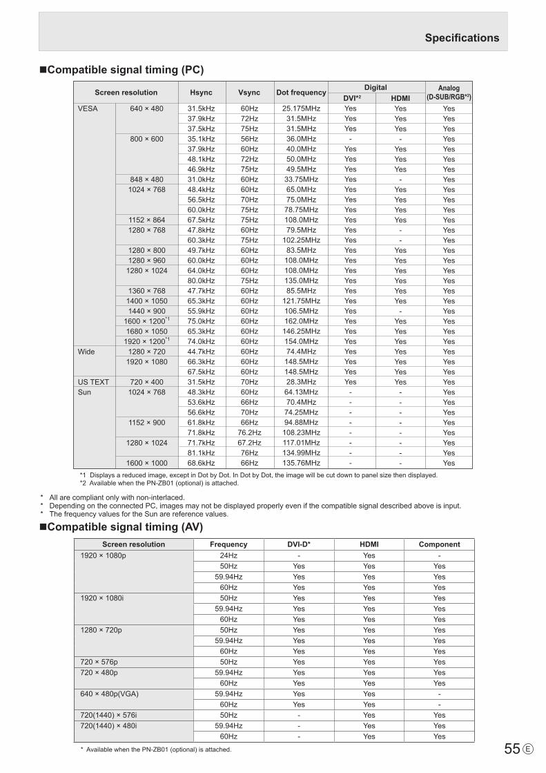
55 E
nCompatible signal timing (PC)
VESA
Wide
US TEXTSun
Screen resolution Hsync Vsync Dot frequency Digital
640 × 480
800 × 600
848 × 4801024 × 768
1152 × 8641280 × 768
1280 × 8001280 × 960
1280 × 1024
1360 × 7681400 × 10501440 × 900
1600 × 1200*1
1680 × 10501920 × 1200*1
1280 × 7201920 × 1080
720 × 4001024 × 768
1152 × 900
1280 × 1024
1600 × 1000
31.5kHz37.9kHz37.5kHz35.1kHz37.9kHz48.1kHz46.9kHz31.0kHz48.4kHz56.5kHz60.0kHz67.5kHz47.8kHz60.3kHz49.7kHz60.0kHz64.0kHz80.0kHz47.7kHz65.3kHz55.9kHz75.0kHz65.3kHz74.0kHz44.7kHz66.3kHz67.5kHz31.5kHz48.3kHz53.6kHz56.6kHz61.8kHz71.8kHz71.7kHz81.1kHz68.6kHz
60Hz72Hz75Hz56Hz60Hz72Hz75Hz60Hz60Hz70Hz75Hz75Hz60Hz75Hz60Hz60Hz60Hz75Hz60Hz60Hz60Hz60Hz60Hz60Hz60Hz60Hz60Hz70Hz60Hz66Hz70Hz66Hz
76.2Hz67.2Hz76Hz66Hz
25.175MHz31.5MHz31.5MHz36.0MHz40.0MHz50.0MHz49.5MHz
33.75MHz65.0MHz75.0MHz
78.75MHz108.0MHz79.5MHz
102.25MHz83.5MHz
108.0MHz108.0MHz135.0MHz85.5MHz
121.75MHz106.5MHz162.0MHz
146.25MHz154.0MHz74.4MHz
148.5MHz148.5MHz28.3MHz
64.13MHz70.4MHz
74.25MHz94.88MHz
108.23MHz117.01MHz134.99MHz135.76MHz
YesYesYes
-YesYesYesYesYesYesYesYesYesYesYesYesYesYesYesYesYesYesYesYesYesYesYesYes
--------
Analog(D-SUB/RGB*2)
YesYesYesYesYesYesYesYesYesYesYesYesYesYesYesYesYesYesYesYesYesYesYesYesYesYesYesYesYesYesYesYesYesYesYesYes
DVI*2 HDMIYesYesYes
-YesYesYes
-YesYesYesYes
--
YesYesYesYesYesYes
-YesYesYesYesYesYesYes
--------
*1 Displays a reduced image, except in Dot by Dot. In Dot by Dot, the image will be cut down to panel size then displayed. *2 Available when the PN-ZB01 (optional) is attached.
* Allarecompliantonlywithnon-interlaced.* DependingontheconnectedPC,imagesmaynotbedisplayedproperlyevenifthecompatiblesignaldescribedaboveisinput.* ThefrequencyvaluesfortheSunarereferencevalues.
nCompatible signal timing (AV)Screen resolution Frequency DVI-D* HDMI Component
1920×1080p 24Hz - Yes -50Hz Yes Yes Yes
59.94Hz Yes Yes Yes60Hz Yes Yes Yes
1920×1080i 50Hz Yes Yes Yes59.94Hz Yes Yes Yes60Hz Yes Yes Yes
1280×720p 50Hz Yes Yes Yes59.94Hz Yes Yes Yes60Hz Yes Yes Yes
720×576p 50Hz Yes Yes Yes720×480p 59.94Hz Yes Yes Yes
60Hz Yes Yes Yes640×480p(VGA) 59.94Hz Yes Yes -
60Hz Yes Yes -720(1440)×576i 50Hz - Yes Yes720(1440)×480i 59.94Hz - Yes Yes
60Hz - Yes Yes
*AvailablewhenthePN-ZB01(optional)isattached.
Specifications

56E
Specifications
nPC/AV DVI-D input terminal pins(DVI-D 24 pin)
No. Function No. Function1 TMDSdata2- 13 N.C.2 TMDSdata2+ 14 +5V3 TMDSdata2/4shield 15 GND4 N.C. 16 Hot-plugdetection5 N.C. 17 TMDSdata0-6 DDCclock 18 TMDSdata0+7 DDCdata 19 TMDSdata0/5shield8 N.C. 20 N.C.9 TMDSdata1- 21 N.C.10 TMDSdata1+ 22 TMDSclockshield11 TMDSdata1/3shield 23 TMDSclock+12 N.C. 24 TMDSclock-
nPC D-sub input terminal pins(Mini D-sub 15 pin)
No. Function No. Function1 Red video signal input 9 +5V2 Greenvideosignalinput 10 GND3 Bluevideosignalinput 11 N.C.4 N.C. 12 DDCdata5 GND 13 Hsync signal input6 GNDforredvideosignal 14 Vsyncsignalinput7 GNDforgreenvideosignal 15 DDCclock8 GNDforbluevideosignal
nPC/AV DVI-D output terminal pins(DVI-D 24 pin)
No. Function No. Function1 TMDSdata2- 13 N.C.2 TMDSdata2+ 14 +5V3 TMDSdata2/4shield 15 GND4 N.C. 16 Hot-plugdetection5 N.C. 17 TMDSdata0-6 DDCclock 18 TMDSdata0+7 DDCdata 19 TMDSdata0/5shield8 N.C. 20 N.C.9 TMDSdata1- 21 N.C.10 TMDSdata1+ 22 TMDSclockshield11 TMDSdata1/3shield 23 TMDSclock+12 N.C. 24 TMDSclock-
nPC/AV HDMI input terminal pins(HDMITM Connector)
No. Function No. Function1 TMDSdata2+ 11 TMDSclockshield2 TMDSdata2shield 12 TMDSclock-3 TMDSdata2- 13 CEC4 TMDSdata1+ 14 N.C.5 TMDSdata1shield 15 SCL6 TMDSdata1- 16 SDA7 TMDSdata0+ 17 DDC/CECGND8 TMDSdata0shield 18 +5V9 TMDSdata0- 19 Hot-plugdetection10 TMDSclock+
nRS-232C input terminal pins(D-sub 9 pin)
No. Function No. Function1 N.C. 6 N.C.2 Transmitted data 7 N.C.3 Received data 8 N.C.4 N.C. 9 N.C.5 GND
nRS-232C output terminal pins(D-sub 9 pin)
No. Function No. Function1 N.C. 6 N.C.2 Received data 7 N.C.3 Transmitted data 8 N.C.4 N.C. 9 N.C.5 GND

57 E
• Wheninstalling,removingormovingthemonitor,ensurethatthisiscarriedoutbyatleast4people.• Besuretouseawall-mountbracketdesignedordesignatedformountingthemonitor.• Thismonitorisdesignedtobeinstalledonaconcretewallorpillar.Reinforcedworkmightbenecessaryforsomematerials
such as plaster / thin plastic board / wood before starting installation. This monitor and bracket must be installed on a wall which can endure at least 4 times or more the weight of the monitor. Install by the most suitable method for the material and the structure.
• ToattachaVESA-compliantmountingbracket,useM6screwsthatare5/16inch(8mm)to3/8inch(10mm)longerthanthethickness of the mounting bracket.
• Aftermounting,pleasecarefullyensurethemonitorissecure,andnotabletocomeloosefromthewallormount.• DonotuseanyscrewholesotherthanVESAholesforinstallation.
Mounting Precautions (For SHARP dealers and service engineers)
nAttaching the Tray1. Remove the cover from the back of the monitor.
2. Secure the tray mounting fitting.Secureusingthescrewremovedinstep1and2M5traymountingscrews(supplied).
Screw removed in step 1
Cover (supplied)
Bracket (supplied)
M5 tray mounting screws(supplied)
Tray mountingfitting
(3)(2)
(1)
3. Secure the tray.Insertthetrayintothetraymountingfittingandsecurewith2M4traymountingscrews(supplied).
Tray(supplied)
M4 tray mounting screws(supplied)

PN-L702B Me EN11J(1)