PMD70, PMD75, FMD76, FMD77, FMD78 - Axon AutomationH Literature/Manuals/menu/docs/IOMs... ·...
32
KA1021P/00/en/12.07 71038584 Brief Operating Instructions Deltabar S PMD70, PMD75, FMD76, FMD77, FMD78 Differential pressure transmitter 8 These are Brief Operating Instructions. For more detailed information, please refer to the Operating Instructions and the additional documentation on the CD-ROM provided. These Brief Operating Instructions are not intended to replace the Operating Instructions provided in the scope of supply. The complete device documentation consists of: • these Brief Operating Instructions • a CD-ROM with: – the Operating Instructions – Technical Information – Approvals and safety certificates.
Transcript of PMD70, PMD75, FMD76, FMD77, FMD78 - Axon AutomationH Literature/Manuals/menu/docs/IOMs... ·...

KA1021P/00/en/12.07
71038584
Brief Operating Instructions
Deltabar SPMD70, PMD75, FMD76, FMD77, FMD78
Differential pressure transmitter
8
These are Brief Operating Instructions.
For more detailed information, please refer to the Operating Instructions and the
additional documentation on the CD-ROM provided.
These Brief Operating Instructions are not intended to replace the Operating
Instructions provided in the scope of supply.
The complete device documentation consists of:
• these Brief Operating Instructions
• a CD-ROM with:
– the Operating Instructions
– Technical Information
– Approvals and safety certificates.
Table of contents Deltabar S PROFIBUS PA
2 Endress+Hauser
Table of contents
1 Safety instructions . . . . . . . . . . . . . . . . . . . . . . . . . . . . . . . . . . . . . . . . . . . . . . . . 31.1 Designated use . . . . . . . . . . . . . . . . . . . . . . . . . . . . . . . . . . . . . . . . . . . . . . . . . . . . . . . . . . . . . . . . . . . . . . . . . . 3
1.2 Installation, commissioning and operation . . . . . . . . . . . . . . . . . . . . . . . . . . . . . . . . . . . . . . . . . . . . . . . . . . . . . . 3
1.3 Operational safety . . . . . . . . . . . . . . . . . . . . . . . . . . . . . . . . . . . . . . . . . . . . . . . . . . . . . . . . . . . . . . . . . . . . . . . . 3
1.4 Return . . . . . . . . . . . . . . . . . . . . . . . . . . . . . . . . . . . . . . . . . . . . . . . . . . . . . . . . . . . . . . . . . . . . . . . . . . . . . . . . 3
1.5 Safety icons . . . . . . . . . . . . . . . . . . . . . . . . . . . . . . . . . . . . . . . . . . . . . . . . . . . . . . . . . . . . . . . . . . . . . . . . . . . . . 4
2 Installation . . . . . . . . . . . . . . . . . . . . . . . . . . . . . . . . . . . . . . . . . . . . . . . . . . . . . . 42.1 General installation instructions . . . . . . . . . . . . . . . . . . . . . . . . . . . . . . . . . . . . . . . . . . . . . . . . . . . . . . . . . . . . . 4
2.2 Measuring arrangement . . . . . . . . . . . . . . . . . . . . . . . . . . . . . . . . . . . . . . . . . . . . . . . . . . . . . . . . . . . . . . . . . . . 5
2.3 Installation instructions for devices with diaphragm seals . . . . . . . . . . . . . . . . . . . . . . . . . . . . . . . . . . . . . . . . . . . 6
2.4 Assembling and mounting the "separate housing" version . . . . . . . . . . . . . . . . . . . . . . . . . . . . . . . . . . . . . . . . . . . 8
3 Wiring . . . . . . . . . . . . . . . . . . . . . . . . . . . . . . . . . . . . . . . . . . . . . . . . . . . . . . . . . 93.1 Connecting the device . . . . . . . . . . . . . . . . . . . . . . . . . . . . . . . . . . . . . . . . . . . . . . . . . . . . . . . . . . . . . . . . . . . . 9
3.2 Connecting the measuring unit . . . . . . . . . . . . . . . . . . . . . . . . . . . . . . . . . . . . . . . . . . . . . . . . . . . . . . . . . . . . . 10
4 Operation. . . . . . . . . . . . . . . . . . . . . . . . . . . . . . . . . . . . . . . . . . . . . . . . . . . . . . 114.1 On-site display (optional) . . . . . . . . . . . . . . . . . . . . . . . . . . . . . . . . . . . . . . . . . . . . . . . . . . . . . . . . . . . . . . . . . 11
4.2 Operating elements . . . . . . . . . . . . . . . . . . . . . . . . . . . . . . . . . . . . . . . . . . . . . . . . . . . . . . . . . . . . . . . . . . . . . . 13
4.3 On-site operation via on-site display . . . . . . . . . . . . . . . . . . . . . . . . . . . . . . . . . . . . . . . . . . . . . . . . . . . . . . . . . 16
4.4 Configuring the device address . . . . . . . . . . . . . . . . . . . . . . . . . . . . . . . . . . . . . . . . . . . . . . . . . . . . . . . . . . . . . 19
4.5 Locking/unlocking operation . . . . . . . . . . . . . . . . . . . . . . . . . . . . . . . . . . . . . . . . . . . . . . . . . . . . . . . . . . . . . . 21
5 Commissioning . . . . . . . . . . . . . . . . . . . . . . . . . . . . . . . . . . . . . . . . . . . . . . . . . 225.1 Position adjustment . . . . . . . . . . . . . . . . . . . . . . . . . . . . . . . . . . . . . . . . . . . . . . . . . . . . . . . . . . . . . . . . . . . . . . 23
5.2 Differential pressure measurement . . . . . . . . . . . . . . . . . . . . . . . . . . . . . . . . . . . . . . . . . . . . . . . . . . . . . . . . . . 24
5.3 Level measurement . . . . . . . . . . . . . . . . . . . . . . . . . . . . . . . . . . . . . . . . . . . . . . . . . . . . . . . . . . . . . . . . . . . . . . 26
5.4 Flow measurement . . . . . . . . . . . . . . . . . . . . . . . . . . . . . . . . . . . . . . . . . . . . . . . . . . . . . . . . . . . . . . . . . . . . . . 29

Deltabar S PROFIBUS PA Safety instructions
Endress+Hauser 3
1 Safety instructions
1.1 Designated use
The Deltabar S is a differential pressure transmitter for measuring differential pressure, level and
flow.
The manufacturer accepts no liability for damages resulting from incorrect use or use other than
that designated.
1.2 Installation, commissioning and operation
• The device must only be installed, connected, commissioned and maintained by qualified and
authorized specialists (e.g. electrical technicians) in full compliance with the instructions in
this manual, the applicable norms, legal regulations and certificates (depending on the
application).
• The specialist must have read and understood this manual and must follow the instructions it
contains. If you are unclear on anything in these Brief Operating Instructions, you must read
the Operating Instructions (on the CD-ROM). The Operating Instructions provide detailed
information on the device/measuring system.
• The device may only be modified or repaired if such work is expressly permitted in the
Operating Instructions (→ see CD-ROM).
• If faults cannot be rectified, the device must be taken out of service and secured against
unintentional commissioning.
• Do not operate damaged devices. Mark them as defective.
1.3 Operational safety
• The device is safely built and tested according to state-of-the-art technology and has left the
factory in perfect condition as regards technical safety. The applicable regulations and
European standards have been taken into account.
• Pay particular attention to the technical data on the nameplate.
• Devices for use in hazardous areas are fitted with an additional nameplate. If the device is to
be installed in an explosion hazardous area, then the specifications in the certificate as well as
all national and local regulations must be observed. The device is accompanied by separate
"Ex documentation", which is an integral part of this Operating Instructions. The installation
regulations, connection values and Safety Instructions listed in this Ex document must be
observed. The documentation number of the related Safety Instructions is also indicated on
the additional nameplate.
1.4 Return
Follow the instructions on returning the device as outlined in the Operating Instructions on the
CD-ROM provided.

Installation Deltabar S PROFIBUS PA
4 Endress+Hauser
1.5 Safety icons
2 Installation
2.1 General installation instructions
# Warning!
The seal is not allowed to press on the diaphragm as this could affect the measurement result.
! Note!
• Due to the orientation of the Deltabar S, there may be a shift in the measured value, i.e. when
the container is empty, the measured value does not display zero. You can correct this zero
point shift either via the "zero" key on the electronic insert, or on the outside of the device or
via the on-site display. → See Page 13, 4.2.1 "Position of operating elements", Page 14,
Section 4.2.2 "Function of the operating elements" or Page 23, Section 5.1 "Position
adjustment".
• For FMD77 and FMD78, please refer to Section 2.3 "Installation instructions for devices with
diaphragm seals", Page 6.
• The FMD77 must only be insulated up to a certain height.
• General recommendations for routing the impulse piping can be found in DIN 19210
"Methods for measurement of fluid flow; differential piping for flow measurement devices" or
the corresponding national or international standards.
• Using a three-valve or five-valve manifold allows for easy commissioning, installation and
maintenance without interrupting the process.
• When routing the impulse piping outdoors, ensure that sufficient anti-freeze protection is
used, e.g. by using pipe heat tracing.
• Install the impulse piping with a monotonic gradient of at least 10%.
• To ensure optimal readability of the on-site display, it is possible to rotate the housing up to
380°.
• Endress+Hauser offers a mounting bracket for installing on pipes or walls.
Symbol Meaning
#Warning!
A warning highlights actions or procedures which, if not performed correctly, will lead to personal injury,
a safety hazard or destruction of the instrument.
"Caution!
Caution highlights actions or procedures which, if not performed correctly, may lead to personal injury or
incorrect functioning of the instrument.
!Note!
A note highlights actions or procedures which, if not performed correctly, may indirectly affect operation
or may lead to an instrument response which is not planned.
Deltabar S PROFIBUS PA Installation
Endress+Hauser 5
2.2 Measuring arrangement
2.2.1 Pressure measurement
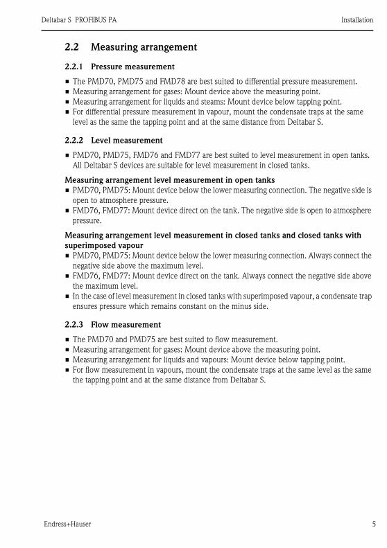
• The PMD70, PMD75 and FMD78 are best suited to differential pressure measurement.
• Measuring arrangement for gases: Mount device above the measuring point.
• Measuring arrangement for liquids and steams: Mount device below tapping point.
• For differential pressure measurement in vapour, mount the condensate traps at the same
level as the same the tapping point and at the same distance from Deltabar S.
2.2.2 Level measurement
• PMD70, PMD75, FMD76 and FMD77 are best suited to level measurement in open tanks.
All Deltabar S devices are suitable for level measurement in closed tanks.
Measuring arrangement level measurement in open tanks
• PMD70, PMD75: Mount device below the lower measuring connection. The negative side is
open to atmosphere pressure.
• FMD76, FMD77: Mount device direct on the tank. The negative side is open to atmosphere
pressure.
Measuring arrangement level measurement in closed tanks and closed tanks with
superimposed vapour
• PMD70, PMD75: Mount device below the lower measuring connection. Always connect the
negative side above the maximum level.
• FMD76, FMD77: Mount device direct on the tank. Always connect the negative side above
the maximum level.
• In the case of level measurement in closed tanks with superimposed vapour, a condensate trap
ensures pressure which remains constant on the minus side.
2.2.3 Flow measurement
• The PMD70 and PMD75 are best suited to flow measurement.
• Measuring arrangement for gases: Mount device above the measuring point.
• Measuring arrangement for liquids and vapours: Mount device below tapping point.
• For flow measurement in vapours, mount the condensate traps at the same level as the same
the tapping point and at the same distance from Deltabar S.
Installation Deltabar S PROFIBUS PA
6 Endress+Hauser
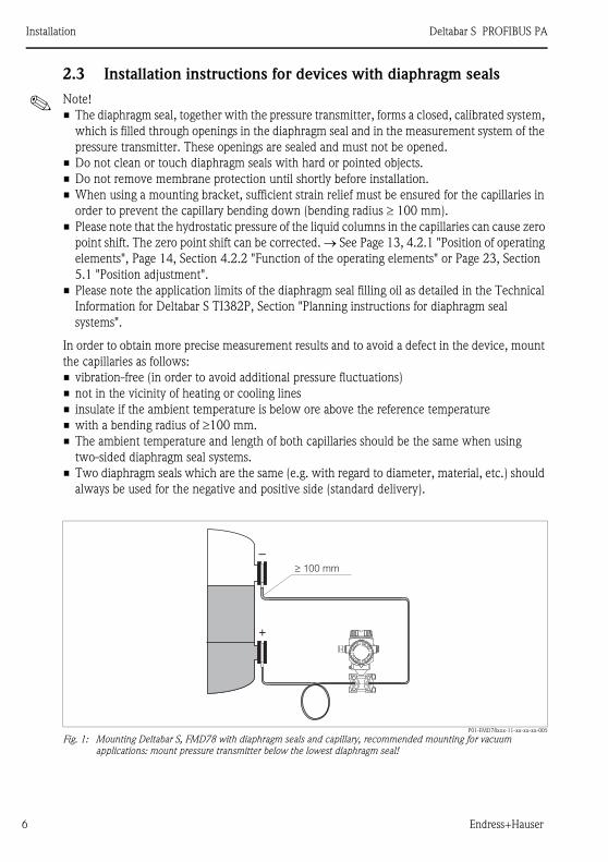
2.3 Installation instructions for devices with diaphragm seals
! Note!
• The diaphragm seal, together with the pressure transmitter, forms a closed, calibrated system,
which is filled through openings in the diaphragm seal and in the measurement system of the
pressure transmitter. These openings are sealed and must not be opened.
• Do not clean or touch diaphragm seals with hard or pointed objects.
• Do not remove membrane protection until shortly before installation.
• When using a mounting bracket, sufficient strain relief must be ensured for the capillaries in
order to prevent the capillary bending down (bending radius ≥ 100 mm).
• Please note that the hydrostatic pressure of the liquid columns in the capillaries can cause zero
point shift. The zero point shift can be corrected. → See Page 13, 4.2.1 "Position of operating
elements", Page 14, Section 4.2.2 "Function of the operating elements" or Page 23, Section
5.1 "Position adjustment".
• Please note the application limits of the diaphragm seal filling oil as detailed in the Technical
Information for Deltabar S TI382P, Section "Planning instructions for diaphragm seal
systems".
In order to obtain more precise measurement results and to avoid a defect in the device, mount
the capillaries as follows:
• vibration-free (in order to avoid additional pressure fluctuations)
• not in the vicinity of heating or cooling lines
• insulate if the ambient temperature is below ore above the reference temperature
• with a bending radius of ≥100 mm.
• The ambient temperature and length of both capillaries should be the same when using
two-sided diaphragm seal systems.
• Two diaphragm seals which are the same (e.g. with regard to diameter, material, etc.) should
always be used for the negative and positive side (standard delivery).
P01-FMD78xxx-11-xx-xx-xx-005
Fig. 1: Mounting Deltabar S, FMD78 with diaphragm seals and capillary, recommended mounting for vacuum
applications: mount pressure transmitter below the lowest diaphragm seal!
+ –
+
–≥ 100 mm
Deltabar S PROFIBUS PA Installation
Endress+Hauser 7
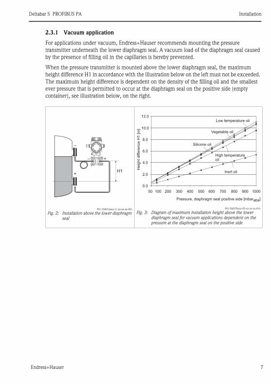
2.3.1 Vacuum application
For applications under vacuum, Endress+Hauser recommends mounting the pressure
transmitter underneath the lower diaphragm seal. A vacuum load of the diaphragm seal caused
by the presence of filling oil in the capillaries is hereby prevented.
When the pressure transmitter is mounted above the lower diaphragm seal, the maximum
height difference H1 in accordance with the illustration below on the left must not be exceeded.
The maximum height difference is dependent on the density of the filling oil and the smallest
ever pressure that is permitted to occur at the diaphragm seal on the positive side (empty
container), see illustration below, on the right.
P01-FMD7xxxx-11-xx-xx-xx-001
Fig. 2: Installation above the lower diaphragm
seal
P01-FMD78xxx-05-xx-xx-xx-016
Fig. 3: Diagram of maximum installation height above the lower
diaphragm seal for vacuum applications dependent on the
pressure at the diaphragm seal on the positive side
+ –
+
–
H1
– +
0.0
2.0
4.0
6.0
8.0
10.0
12.0
50 100 300 400 500 600 700 800 900 1000200
Inert oil
High temperatureoil
Vegetable oil
Silicone oil
Pressure, diaphragm seal positive side [mbarabs]
He
igh
td
iffe
ren
ce
H1
[m]
Low temperature oil
Installation Deltabar S PROFIBUS PA
8 Endress+Hauser
2.4 Assembling and mounting the "separate housing" version
P01-xMD7xxxx-11-xx-xx-xx-011
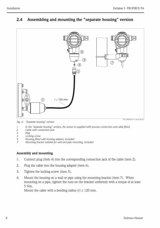
Fig. 4: "Separate housing" version
1 In the "separate housing" version, the sensor is supplied with process connection and cable fitted.
2 Cable with connection jack
4 Plug
5 Locking screw
6 Housing fitted with housing adapter, included
7 Mounting bracket suitable for wall and pipe mounting, included
Assembly and mounting
1. Connect plug (item 4) into the corresponding connection jack of the cable (item 2).
2. Plug the cable into the housing adapter (item 6).
3. Tighten the locking screw (item 5).
4. Mount the housing on a wall or pipe using the mounting bracket (item 7). When
mounting on a pipe, tighten the nuts on the bracket uniformly with a torque of at least
5 Nm.
Mount the cable with a bending radius (r) ≥ 120 mm.
r � 120 mm1
2
4
5
6
7

Deltabar S PROFIBUS PA Wiring
Endress+Hauser 9
3 Wiring
# Warning!
• When using the measuring device in hazardous areas, installation must comply with the
corresponding national standards and regulations and the Safety Instructions or Installation or
Control Drawings.
3.1 Connecting the device
! Note!
• Devices with integrated overvoltage protection must be earthed.
• Protective circuits against reverse polarity, HF influences and overvoltage peaks are installed.
• The supply voltage must match the supply voltage on the nameplate.
• Switch off the supply voltage before connecting the device.
• Remove housing cover of the terminal compartment.
• Guide cable through the gland. Preferably use twisted, screened two-wire cable.
• Connect device in accordance with the following diagram.
• Screw down housing cover.
• Switch on supply voltage.
P01-xMx7xxxx-04-xx-xx-xx-008
Fig. 5: Electrical connection PROFIBUS PA → Observe also the following section.
For devices with 7/8" or M12 plug see Operating Instructions.
1 Housing
2 Internal earth terminal
3 External earth terminal
4 Supply voltage, for version in non-hazardous area = 9...32 V DC
5 Devices with integrated overvoltage protection are labelled OVP (overvoltage protection) here.
➀
➁
➂
➃
➄
PA PA
PA PA

Wiring Deltabar S PROFIBUS PA
10 Endress+Hauser
3.2 Connecting the measuring unit
3.2.1 Supply voltage
• Version for non-hazardous area: 9...32 V DC
3.2.2 Current consumption
11 mA ±1 mA, switch-on current corresponds to 61158-2, Clause 21.
3.2.3 Cable specification
• Use a twisted, screened two-wire cable, preferably cable type A.
• Terminals for wire cross-sections: 0.5...2.5 mm2
• Outer cable diameter: 5...9 mm
! Note!
For further information on the cable specifications, see Operating Instructions BA034S
"Guidelines for planning and commissioning PROFIBUS DP/PA", PNO Guideline 2.092
"PROFIBUS PA User and Installation Guideline" and IEC 61158-2 (MBP).
3.2.4 Earthing and screening
Deltabar S must be earthed, for example by means of the external earth terminal.
Different earthing and screening installation methods are available for PROFIBUS PA networks
such as:
• Isolated installation (see also IEC 61158-2)
• Installation with multiple earthing
• Capacitive installation
Deltabar S PROFIBUS PA Operation
Endress+Hauser 11
4 Operation
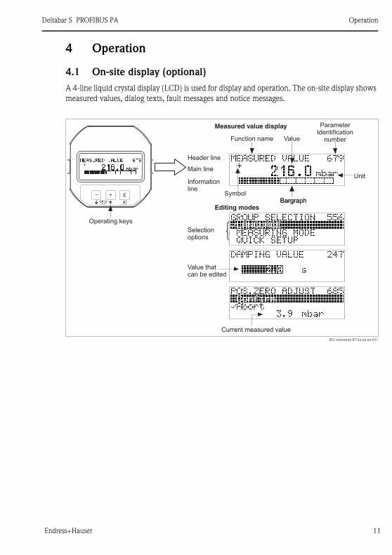
4.1 On-site display (optional)
A 4-line liquid crystal display (LCD) is used for display and operation. The on-site display shows
measured values, dialog texts, fault messages and notice messages.
P01-xxxxxxxx-07-xx-xx-xx-011
E+–
Bargraph
Operating keys
SymbolBargraph
ValueFunction name
Measured value display
Unit
Header line
Informationline
Main line
ParameterIdentification
number
Editing modes
Selectionoptions
Value thatcan be edited
Current measured value
Operation Deltabar S PROFIBUS PA
12 Endress+Hauser
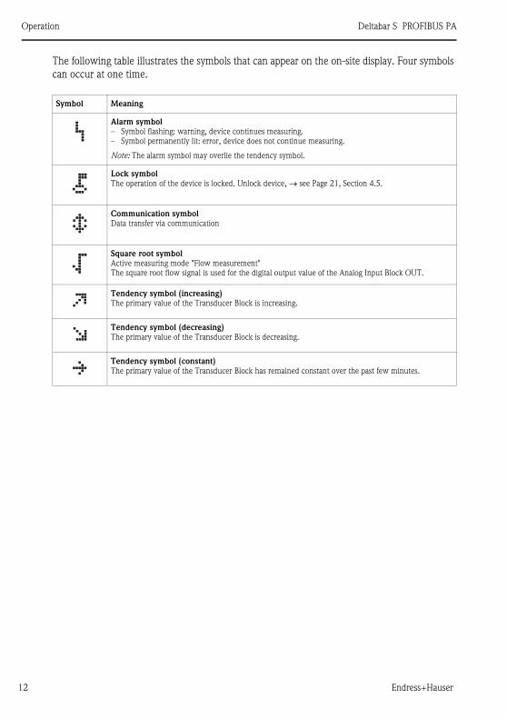
The following table illustrates the symbols that can appear on the on-site display. Four symbols
can occur at one time.
Symbol Meaning
Alarm symbol
– Symbol flashing: warning, device continues measuring.
– Symbol permanently lit: error, device does not continue measuring.
Note: The alarm symbol may overlie the tendency symbol.
Lock symbol
The operation of the device is locked. Unlock device, → see Page 21, Section 4.5.
Communication symbol
Data transfer via communication
Square root symbol
Active measuring mode "Flow measurement"
The square root flow signal is used for the digital output value of the Analog Input Block OUT.
Tendency symbol (increasing)
The primary value of the Transducer Block is increasing.
Tendency symbol (decreasing)
The primary value of the Transducer Block is decreasing.
Tendency symbol (constant)
The primary value of the Transducer Block has remained constant over the past few minutes.
Deltabar S PROFIBUS PA Operation
Endress+Hauser 13
4.2 Operating elements
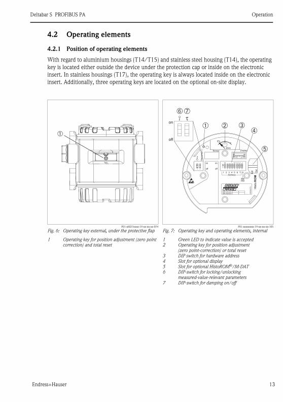
4.2.1 Position of operating elements
With regard to aluminium housings (T14/T15) and stainless steel housing (T14), the operating
key is located either outside the device under the protection cap or inside on the electronic
insert. In stainless housings (T17), the operating key is always located inside on the electronic
insert. Additionally, three operating keys are located on the optional on-site display.
P01-xMD7xxxx-19-xx-xx-xx-074
Fig. 6: Operating key external, under the protective flap
1 Operating key for position adjustment (zero point
correction) and total reset
P01-xxxxxxxx-19-xx-xx-xx-105
Fig. 7: Operating key and operating elements, internal
1 Green LED to indicate value is accepted
2 Operating key for position adjustment
(zero point-correction) or total reset
3 DIP switch for hardware address
4 Slot for optional display
5 Slot for optional HistoROM®/M-DAT
6 DIP-switch for locking/unlocking
measured-value-relevant parameters
7 DIP-switch for damping on/off
➀
0%
Zero
DisplaySensor
on
off
0%
Zero
Address
SWHW
1 2 3 4 5 6 7 8
on
off
His
toR
OM
on
off
➀ ➁ ➂➃
➄
➆➅�
PC
21 21
CKON
3 4 5 6 7 8
S D A 0 8
HW-Version:SW-Version: 2
50
00
22
72
-–
12

Operation Deltabar S PROFIBUS PA
14 Endress+Hauser
4.2.2 Function of the operating elements – on-site display not connected
Operating key(s) Meaning
P02-xxxxxxxx-19-xx-xx-xx-107
– Position adjustment (zero point correction): Press key for at least 3 seconds. If the
LED on the electronic insert lights up briefly, the pressure applied has been
accepted for position adjustment.
→ See also Page 25 (Pressure measuring mode), Page 28 (Level measuring mode)
or Page 30 (Flow measuring mode).
– Total reset: Press key for at least 12 seconds. If the LED on the electronic insert
lights up briefly, the reset is being carried out.
P01-xxxxxxxx-19-xx-xx-xx-109
Set address in the bus. → See also Page 19, Section 4.4 "Configuring the device
address".
P01-xxxxxxxx-19-xx-xx-xx-108
– DIP-switch 1: for locking/unlocking measured-value-relevant parameters
Factory setting: off (unlocked)
– DIP switch 2: damping on/off
Factory setting: on (damping on)
0%
Zero
on
off1 2 3 4 5 6 7 8
Address
21
CKON
3 4 5 6 7 8
S D A 0 8
0 1
SWHW
1 2
on
off
τ

Deltabar S PROFIBUS PA Operation
Endress+Hauser 15
4.2.3 Function of the operating elements – on-site display connected
Operating key(s) Meaning
O – Navigate upwards in the picklist
– Edit the numerical values and characters within a function
S – Navigate downwards in the picklist
– Edit the numerical values and characters within a function
F – Confirm entry
– Jump to the next item
O and FContrast setting of on-site display: darker
S and FContrast setting of on-site display: brighter
O and S
ESC functions:
– Exit edit mode without saving the changed value.
– You are in a menu within a function group. The first time you press the keys
simultaneously, you go back a parameter within the function group. Each time you
press the keys simultaneously after that, you go up a level in the menu.
– You are in a menu at a selection level. Each time you press the keys simultaneously,
you go up a level in the menu.
Note: The terms function group, level and selection level are explained in Section
4.3.1, Page 16.
P01-xxxxxxxx-19-xx-xx-xx-109
Set address in the bus. → See also Page 19, Section 4.4 "Configuring the device
address".
P01-xxxxxxxx-19-xx-xx-xx-057
– DIP-switch 1: for locking/unlocking measured-value-relevant parameters
Factory setting: off (unlocked)
– DIP-switch 2: damping on/off,
Factory setting: on (damping on)
on
off1 2 3 4 5 6 7 8
Address
21
CKON
3 4 5 6 7 8
S D A 0 8
0 1
SWHW
1 2
τon
off
Operation Deltabar S PROFIBUS PA
16 Endress+Hauser
4.3 On-site operation via on-site display
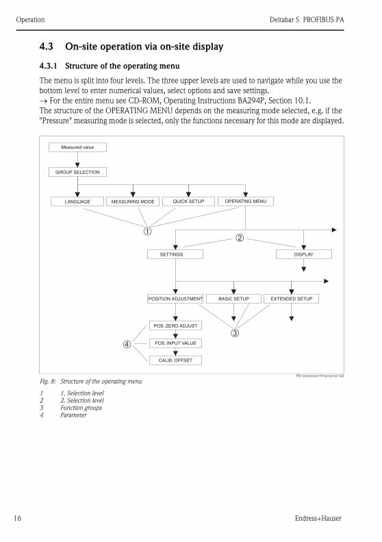
4.3.1 Structure of the operating menu
The menu is split into four levels. The three upper levels are used to navigate while you use the
bottom level to enter numerical values, select options and save settings.
→ For the entire menu see CD-ROM, Operating Instructions BA294P, Section 10.1.
The structure of the OPERATING MENU depends on the measuring mode selected, e.g. if the
"Pressure" measuring mode is selected, only the functions necessary for this mode are displayed.
P01-xxxxxxxx-19-xx-xx-xx-145
Fig. 8: Structure of the operating menu
1 1. Selection level
2 2. Selection level
3 Function groups
4 Parameter
➀
➂
➁
➃
Measured value
GROUP SELECTION
DISPLAYSETTINGS
EXTENDED SETUP
POS. ZERO ADJUST
POS. INPUT VALUE
CALIB. OFFSET
POSITION ADJUSTMENT BASIC SETUP
OPERATING MENUQUICK SETUPMEASURING MODELANGUAGE

Deltabar S PROFIBUS PA Operation
Endress+Hauser 17
4.3.2 Selecting an option
Example: select "English" as the language of the menu.
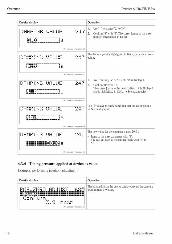
4.3.3 Editing a value
Example: adjusting DAMPING VALUE function from 2.0 s to 30.0 s. → See also Page 15,
Section 4.2.3 "Function of the operating elements".
On-site display Operation
P01-xxxxxxxx-19-xx-xx-xx-017
German is selected as the language. A ✓in front of the
menu text indicates the active option.
P01-xxxxxxxx-19-xx-xx-xx-033
Select English with "+" or "–".
P01-xxxxxxxx-19-xx-xx-xx-034
1. Confirm your choice with "E". A ✓ in front of the
menu text indicates the active option. (English is now
selected as the menu language.)
2. Jump to the next item with "E".
On-site display Operation
P01-xxxxxxxx-19-xx-xx-xx-023
The on-site display shows the parameter to be changed.
The value highlighted in black can be changed. The "s"
unit is fixed and cannot be changed.
P01-xxxxxxxx-19-xx-xx-xx-027
1. Press "+" or "–" to get to the editing mode.
2. The first digit is highlighted in black.
Operation Deltabar S PROFIBUS PA
18 Endress+Hauser
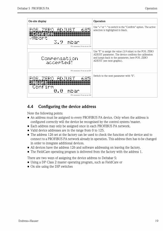
4.3.4 Taking pressure applied at device as value
Example: performing position adjustment.
P01-xxxxxxxx-19-xx-xx-xx-028
1. Use "+" to change "2" to "3".
2. Confirm "3" with "E". The cursor jumps to the next
position (highlighted in black).
P01-xxxxxxxx-19-xx-xx-xx-029
The decimal point is highlighted in black, i.e. you can now
edit it.
P01-xxxxxxxx-19-xx-xx-xx-030
1. Keep pressing "+" or "–" until "0" is displayed.
2. Confirm "0" with "E".
The cursor jumps to the next position. ↵ is displayed
and is highlighted in black. → See next graphic.
P01-xxxxxxxx-19-xx-xx-xx-031
Use "E" to save the new value and exit the editing mode.
→ See next graphic.
P01-xxxxxxxx-19-xx-xx-xx-032
The new value for the damping is now 30.0 s.
– Jump to the next parameter with "E".
– You can get back to the editing mode with "+" or
"–".
On-site display Operation
P01-xxxxxxxx-19-xx-xx-xx-158
The bottom line on the on-site display displays the pressure
present, here 3.9 mbar.
On-site display Operation
Deltabar S PROFIBUS PA Operation
Endress+Hauser 19
4.4 Configuring the device address
Note the following points:
• An address must be assigned to every PROFIBUS PA device. Only when the address is
configured correctly will the device be recognised by the control system/master.
• Each address may only be assigned once in each PROFIBUS PA network.
• Valid device addresses are in the range from 0 to 125.
• The address 126 set at the factory can be used to check the function of the device and to
connect to a PROFIBUS PA network already in operation. This address then has to be changed
in order to integrate additional devices.
• All devices have the address 126 and software addressing on leaving the factory.
• The FieldCare operating program is delivered from the factory with the address 1.
There are two ways of assigning the device address to Deltabar S:
• Using a DP Class 2 master operating program, such as FieldCare or
• On site using the DIP switches
P01-xxxxxxxx-19-xx-xx-xx-159
Use "+" or "–" to switch to the "Confirm" option. The active
selection is highlighted in black.
P01-xxxxxxxx-19-xx-xx-xx-037
Use "E" to assign the value (3.9 mbar) to the POS. ZERO
ADJUST parameter. The device confirms the calibration
and jumps back to the parameter, here POS. ZERO
ADJUST (see next graphic).
P01-xxxxxxxx-19-xx-xx-xx-160
Switch to the next parameter with "E".
On-site display Operation

Operation Deltabar S PROFIBUS PA
20 Endress+Hauser
P01-xxxxxxxx-19-xx-xx-xx-112
Fig. 9: Configuring the device address using the DIP switches
1 If necessary, remove on-site display (optional)
2 Set the hardware address via the DIP switches
4.4.1 Hardware addressing
Hardware addressing is configured as follows:
1. Set DIP switch 8 (SW/HW) to "Off".
2. Configure the address with DIP switches 1 to 7.
3. You have to wait 10 seconds for a change in address to take effect. The device is restarted.
➀ ➁
on
off
2 3 4 5 6 7 8
Address
21
CKON
3 4 5 6 7 8
S D A 0 8
0 1
SWHW
2 + 8 = 10
1
E+–
DisplaySensor
on
off
0%
Zero
Address
SWHW
1 2 3 4 5 6 7 8
on
off
His
toR
OM
PC
21 21
CKON
3 4 5 6 7 8
S D A 0 8
HW-Version:SW-Version: 2
50002272-–
12
DIP switch 1 2 3 4 5 6 7
Weighting in Position "On" 1 2 4 8 16 32 64
Weighting in Position "Off" 0 0 0 0 0 0 0
Deltabar S PROFIBUS PA Operation
Endress+Hauser 21
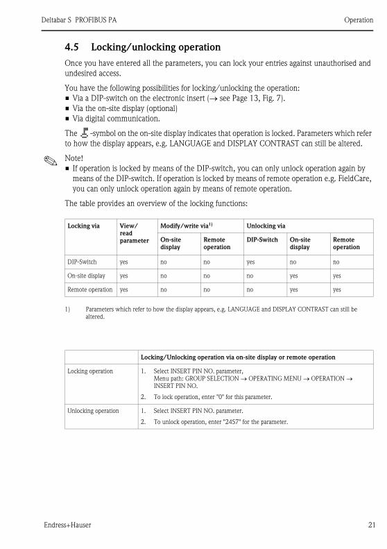
4.5 Locking/unlocking operation
Once you have entered all the parameters, you can lock your entries against unauthorised and
undesired access.
You have the following possibilities for locking/unlocking the operation:
• Via a DIP-switch on the electronic insert (→ see Page 13, Fig. 7).
• Via the on-site display (optional)
• Via digital communication.
The -symbol on the on-site display indicates that operation is locked. Parameters which refer
to how the display appears, e.g. LANGUAGE and DISPLAY CONTRAST can still be altered.
! Note!
• If operation is locked by means of the DIP-switch, you can only unlock operation again by
means of the DIP-switch. If operation is locked by means of remote operation e.g. FieldCare,
you can only unlock operation again by means of remote operation.
The table provides an overview of the locking functions:
Locking via View/
read
parameter
Modify/write via1)
1) Parameters which refer to how the display appears, e.g. LANGUAGE and DISPLAY CONTRAST can still be
altered.
Unlocking via
On-site
display
Remote
operation
DIP-Switch On-site
display
Remote
operation
DIP-Switch yes no no yes no no
On-site display yes no no no yes yes
Remote operation yes no no no yes yes
Locking/Unlocking operation via on-site display or remote operation
Locking operation 1. Select INSERT PIN NO. parameter,
Menu path: GROUP SELECTION → OPERATING MENU → OPERATION → INSERT PIN NO.
2. To lock operation, enter "0" for this parameter.
Unlocking operation 1. Select INSERT PIN NO. parameter.
2. To unlock operation, enter "2457" for the parameter.
Commissioning Deltabar S PROFIBUS PA
22 Endress+Hauser
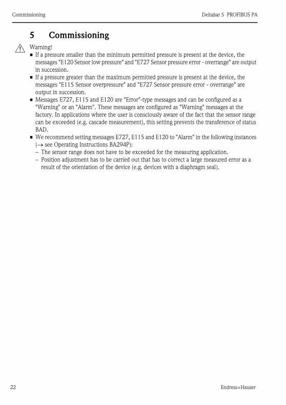
5 Commissioning
# Warning!
• If a pressure smaller than the minimum permitted pressure is present at the device, the
messages "E120 Sensor low pressure" and "E727 Sensor pressure error - overrange" are output
in succession.
• If a pressure greater than the maximum permitted pressure is present at the device, the
messages "E115 Sensor overpressure" and "E727 Sensor pressure error - overrange" are
output in succession.
• Messages E727, E115 and E120 are "Error"-type messages and can be configured as a
"Warning" or an "Alarm". These messages are configured as "Warning" messages at the
factory. In applications where the user is consciously aware of the fact that the sensor range
can be exceeded (e.g. cascade measurement), this setting prevents the transference of status
BAD.
• We recommend setting messages E727, E115 and E120 to "Alarm" in the following instances
(→ see Operating Instructions BA294P):
– The sensor range does not have to be exceeded for the measuring application.
– Position adjustment has to be carried out that has to correct a large measured error as a
result of the orientation of the device (e.g. devices with a diaphragm seal).

Deltabar S PROFIBUS PA Commissioning
Endress+Hauser 23
5.1 Position adjustment
Due to the orientation of the device, there may be a shift in the measured value, i.e. when the
container is empty, the measured value parameter does not display zero. There are three options
to choose from when performing position adjustment.
(Menu path: GROUP SELECTION → OPERATING MENU → SETTINGS → POSITION
ADJUSTMENT)
Parameter name Description
POS. ZERO ADJUST (685)
Entry
Position adjustment – the pressure difference between zero (set point) and the measured
pressure need not be known. (A reference pressure is present at the device.)
Example:
– MEASURED VALUE = 2.2 mbar
– Correct the MEASURED VALUE via the POS. ZERO ADJUST parameter with the
"Confirm" option. This means that you are assigning the value 0.0 to the pressure
present.
– MEASURED VALUE (after pos. zero adjust) = 0.0 mbar
The CALIB. OFFSET parameter displays the resulting pressure difference (offset) by which
the MEASURED VALUE was corrected.
Factory setting:
0
POS. INPUT VALUE
(563)
Entry
Position adjustment – the pressure difference between zero (set point) and the measured
pressure need not be known. (A reference pressure is present at the device.)
Example:
– MEASURED VALUE = 0.5 mbar
– For the POS. INPUT VALUE parameter, specify the desired set point for the
MEASURED VALUE, e.g. 2 mbar.
(MEASURED VALUEnew = POS. INPUT VALUE)
– MEASURED VALUE (after entry for POS. INPUT VALUE) = 2.0 mbar
– The CALIB. OFFSET parameter displays the resulting pressure difference (offset) by
which the MEASURED VALUE was corrected.
CALIB. OFFSET = MEASURED VALUEold – POS. INPUT VALUE,
here: CALIB. OFFSET = 0.5 mbar – 2.0 mbar = – 1.5 mbar)
Factory setting:
0
CALIB. OFFSET (319)
Entry
Position adjustment – the pressure difference between zero (set point) and the measured
pressure is known.
Example:
– MEASURED VALUE = 2.2 mbar
– Via the CALIB. OFFSET parameter, enter the value by which the MEASURED VALUE
should be corrected. To correct the MEASURED VALUE to 0.0 mbar, you must enter
the value 2.2 here.
(MEASURED VALUE new = MEASURED VALUEold – CALIB. OFFSET)
– MEASURED VALUE (after entry for calib. offset) = 0.0 mbar
Factory setting:
0
Commissioning Deltabar S PROFIBUS PA
24 Endress+Hauser
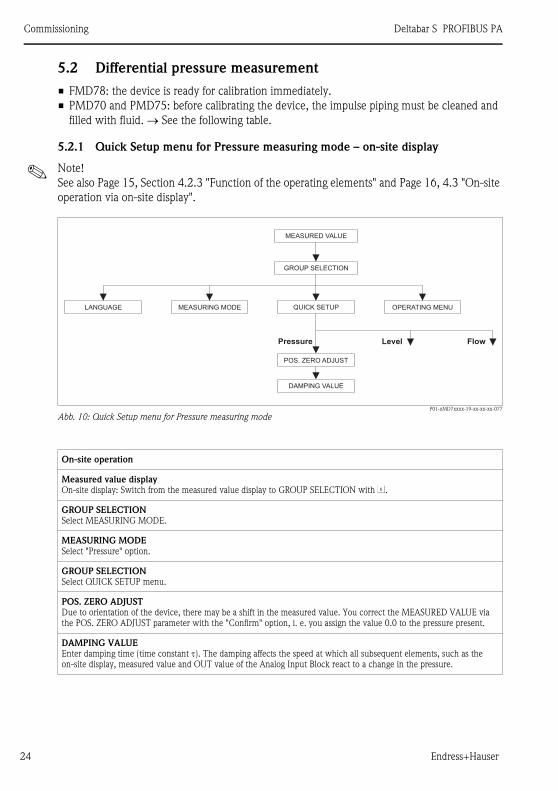
5.2 Differential pressure measurement
• FMD78: the device is ready for calibration immediately.
• PMD70 and PMD75: before calibrating the device, the impulse piping must be cleaned and
filled with fluid. → See the following table.
5.2.1 Quick Setup menu for Pressure measuring mode – on-site display
! Note!
See also Page 15, Section 4.2.3 "Function of the operating elements" and Page 16, 4.3 "On-site
operation via on-site display".
P01-xMD7xxxx-19-xx-xx-xx-077
Abb. 10: Quick Setup menu for Pressure measuring mode
GROUP SELECTION
MEASURING MODELANGUAGE OPERATING MENU
POS. ZERO ADJUST
DAMPING VALUE
FlowPressure Level
MEASURED VALUE
QUICK SETUP
On-site operation
Measured value display
On-site display: Switch from the measured value display to GROUP SELECTION with F.
GROUP SELECTION
Select MEASURING MODE.
MEASURING MODE
Select "Pressure" option.
GROUP SELECTION
Select QUICK SETUP menu.
POS. ZERO ADJUST
Due to orientation of the device, there may be a shift in the measured value. You correct the MEASURED VALUE via
the POS. ZERO ADJUST parameter with the "Confirm" option, i. e. you assign the value 0.0 to the pressure present.
DAMPING VALUE
Enter damping time (time constant τ). The damping affects the speed at which all subsequent elements, such as the
on-site display, measured value and OUT value of the Analog Input Block react to a change in the pressure.

Deltabar S PROFIBUS PA Commissioning
Endress+Hauser 25
5.2.2 On-site operation – on-site display not connected
If no on-site display is connected, the following functions are possible by means of the key on
the electronic insert or on the exterior of the device:
• Position adjustment (zero point correction)
• Device reset, → see also Page 14, Section 4.2.2 "Function of the operating elements", Table.
! Note!
• The operation must be unlocked. → See page 21, Section 4.5 "Locking/unlocking operation".
• The pressure applied must be within the nominal pressure limits of the sensor. See
information on the nameplate.
Carry out position adjustment:
1. Pressure is present at device.
2. Press key for at least 3 seconds. → See Page 13, Section 4.2.1 "Position of operating
elements".
3. If the LED on the electronic insert lights up briefly, the pressure applied has been accepted
for position adjustment.
If the LED does not light up, the pressure applied was not accepted. Observe the input
limits.
Commissioning Deltabar S PROFIBUS PA
26 Endress+Hauser
5.3 Level measurement
Open container
• FMD76 and FMD77: the device is ready for calibration immediately after opening a shut-off
valve (may or may not be present).
• PMD70 and PMD75: before calibrating the device, the impulse piping must be cleaned and
filled with fluid.
Closed Container
• FMD76 and FMD77: the device is ready for calibration immediately after opening a shut-off
valve (may or may not be present).
• FMD78: the device is ready for calibration immediately.
• PMD70 and PMD75: before calibrating the device, the impulse piping must be cleaned and
filled with fluid.
Containers with superimposed steam
• FMD76 and FMD77: the device is ready for calibration immediately after opening a shut-off
valve (may or may not be present).
• FMD78: the device is ready for calibration immediately.
• PMD70 and PMD75: before calibrating the device, the impulse piping must be cleaned and
filled with fluid.
5.3.1 Quick Setup menu for Level measuring mode – on-site display
! Note!
• Some parameters are only displayed if other parameters are appropriately configured (see the
following table).
• The following parameters are set to the following values in the factory:
– LEVEL SELETION: Level Easy Pressure
– CALIBRATION MODE: Wet
– OUTPUT UNIT or LIN. MEASURAND: %
– EMPTY CALIB.: 0.0
– FULL CALIB.: 100.0
• → For parameter description see CD-ROM, Operating Instructions BA296P.
• The quick setup is suitable for simple and quick commissioning. If you wish to make more
complex settings, e.g. change the unit from "%" to "m", you will have to calibrate using the
BASIC SETTINGS group.
• See also Page 15, Section 4.2.3 "Function of the operating elements" and Page 16,
4.3 "On-site operation via on-site display".

Deltabar S PROFIBUS PA Commissioning
Endress+Hauser 27
P01-xMD7xxxx-19-xx-xx-xx-075
Abb. 11: Quick Setup menu for Level measuring mode
1)
1)1) – LEVEL SELECTION "Level Easy Pressure"
and CALIBRATION MODE "Wet"– LEVEL SELECTION = "Level Standard",
LEVEL MODE = "Linear" andCALIBRATION MODE = "Wet"
POS. ZERO ADJUST
EMPTY CALIB.
FULL CALIB.
DAMPING VALUE
FlowPressure Level
MEASURED VALUE
QUICK SETUPLANGUAGE OPERATING MENUMEASURING MODE
GROUP SELECTION
LEVEL SELECTION
On-site operation
Measured value display
On-site display: Switch from the measured value display to GROUP SELECTION with F.
GROUP SELECTION
Select MEASURING MODE.
MEASURING MODE
Select "Level" option.
LEVEL SELECTION
Select level mode.
GROUP SELECTION
Select QUICK SETUP menu.
POS. ZERO ADJUST
Due to orientation of the device, there may be a shift in the measured value. You correct the MEASURED VALUE via
the POS. ZERO ADJUST parameter with the "Confirm" option, i. e. you assign the value 0.0 to the pressure present.
EMPTY CALIB. 1)
Enter level for the lower calibration point.
For this parameter, enter a level value which is assigned to the pressure present at the device.
FULL CALIB. 1)
Enter level for the upper calibration point.
For this parameter, enter a level value which is assigned to the pressure present at the device.
Commissioning Deltabar S PROFIBUS PA
28 Endress+Hauser
5.3.2 On-site operation – on-site display not connected
If no on-site display is connected, the following functions are possible by means of the key on
the electronic insert or on the exterior of the device:
• Position adjustment (zero point correction)
• Device reset, → see also Page 14, Section 4.2.2 "Function of the operating elements", Table.
! Note!
• The operation must be unlocked. → See page 21, Section 4.5 "Locking/unlocking operation".
• The pressure applied must be within the nominal pressure limits of the sensor. See
information on the nameplate.
Carry out position adjustment:
1. Pressure is present at device.
2. Press key for at least 3 seconds. → See Page 13, Section 4.2.1 "Position of operating
elements".
3. If the LED on the electronic insert lights up briefly, the pressure applied has been accepted
for position adjustment.
If the LED does not light up, the pressure applied was not accepted. Observe the input
limits.
On-site operation
DAMPING TIME
Enter damping time (time constant τ). The damping affects the speed at which all subsequent elements, such as the
on-site display, measured value and OUT value of the Analog Input Block react to a change in the pressure.
1) – LEVEL SELECTION "Level Easy Pressure" and CALIBRATION MODE "Wet"
– LEVEL SELECTION "Level Standard", LEVEL MODE "Linear" and CALIBRATION MODE "Wet"
(Menu path for CALIBRATION MODE: GROUP SELECTION → OPERATING MENU → SETTINGS → BASIC SETTINGS)
Deltabar S PROFIBUS PA Commissioning
Endress+Hauser 29
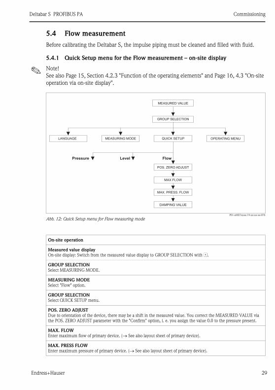
5.4 Flow measurement
Before calibrating the Deltabar S, the impulse piping must be cleaned and filled with fluid.
5.4.1 Quick Setup menu for the Flow measurement – on-site display
! Note!
See also Page 15, Section 4.2.3 "Function of the operating elements" and Page 16, 4.3 "On-site
operation via on-site display".
P01-xMD7xxxx-19-xx-xx-xx-076
Abb. 12: Quick Setup menu for Flow measuring mode
OPERATING MENU
MAX FLOW
MAX. PRESS. FLOW
POS. ZERO ADJUST
DAMPING VALUE
FlowPressure Level
MEASURED VALUE
QUICK SETUP
GROUP SELECTION
MEASURING MODELANGUAGE
On-site operation
Measured value display
On-site display: Switch from the measured value display to GROUP SELECTION with F.
GROUP SELECTION
Select MEASURING MODE.
MEASURING MODE
Select "Flow" option.
GROUP SELECTION
Select QUICK SETUP menu.
POS. ZERO ADJUST
Due to orientation of the device, there may be a shift in the measured value. You correct the MEASURED VALUE via
the POS. ZERO ADJUST parameter with the "Confirm" option, i. e. you assign the value 0.0 to the pressure present.
MAX. FLOW
Enter maximum flow of primary device. (→ See also layout sheet of primary device).
MAX. PRESS FLOW
Enter maximum pressure of primary device. (→ See also layout sheet of primary device).
Commissioning Deltabar S PROFIBUS PA
30 Endress+Hauser
5.4.2 On-site operation – on-site display not connected
If no on-site display is connected, the following functions are possible by means of the key on
the electronic insert or on the exterior of the device:
• Position adjustment (zero point correction)
• Device reset, → see also Page 14, Section 4.2.2 "Function of the operating elements", Table.
! Note!
• The operation must be unlocked. → See page 21, Section 4.5 "Locking/unlocking operation".
• The pressure applied must be within the nominal pressure limits of the sensor. See
information on the nameplate.
Carry out position adjustment:
1. Pressure is present at device.
2. Press key for at least 3 seconds. → See Page 13, Section 4.2.1 "Position of operating
elements".
3. If the LED on the electronic insert lights up briefly, the pressure applied has been accepted
for position adjustment.
If the LED does not light up, the pressure applied was not accepted. Observe the input
limits.
DAMPING TIME
Enter damping time (time constant τ). The damping affects the speed at which all subsequent elements, such as the
on-site display, measured value and OUT value of the Analog Input Block react to a change in the pressure.
On-site operation

Deltabar S PROFIBUS PA Commissioning
Endress+Hauser 31

www.endress.com/worldwide
KA1021P/00/en/12.07
71038584
CCS/FM+SGML 6.071038584