
Pluto Hardware Manual (English - pdf - Manual) - ABB Group · Original instructions English v 12A...
56
Original instructions English v12A 2TLC172001M0212_A PLUTO Safety-PLC Operating instructions Hardware
Transcript of Pluto Hardware Manual (English - pdf - Manual) - ABB Group · Original instructions English v 12A...
Original instructions
English v12A 2TLC172001M0212_A
PLUTO Safety-PLC
Operating instructions
Hardware

2 2TLC172001M0212_A
Table of contents: 1 General ............................................................................................................................ 4 2 Enclosure ......................................................................................................................... 5 3 Electrical installation ......................................................................................................... 5 4 Inputs and outputs ............................................................................................................ 6 4.1 I.. Digital failsafe inputs .................................................................................................. 12 4.2 IQ.. Digital failsafe inputs / Digital outputs (non failsafe) ................................................. 13 4.2.1 Dynamic signals ............................................................................................................. 13 4.2.2 Current monitoring IQ16, IQ17 (Only A20) ...................................................................... 13 4.3 Analogue inputs.............................................................................................................. 14 4.3.1 Analogue inputs 0-10V / 4-20mA (Pluto D20 and D45) ................................................... 14 4.3.1.1 Safety in application ....................................................................................................... 14 4.3.1.1.1 Dual channel solutions ................................................................................................... 14 4.3.1.1.2 Single channel solution ................................................................................................... 14 4.3.1.2 0 Volt .............................................................................................................................. 15 4.3.2 Possible architectures, achievable safety levels and prerequisites ................................. 15 4.3.2.1 Connection of analogue voltage output sensors (0-10V) ................................................ 16 4.3.3 Analogue inputs (0 – 27V) .............................................................................................. 16 4.4 Counter inputs Pluto D45 ............................................................................................... 17 4.4.1 Up count ......................................................................................................................... 17 4.4.2 Up/Down count ............................................................................................................... 18 4.4.3 Sensor output types ....................................................................................................... 19 4.4.4 “No Filt” settings for counters .......................................................................................... 19 4.4.5 Speed monitoring with two sensors ................................................................................ 19 4.4.6 Speed monitoring with one sensor ................................................................................. 20 4.4.7 Possible architectures, achievable safety levels and prerequisites ................................. 21 4.4.7.1 Application examples...................................................................................................... 21 4.5 Failsafe outputs .............................................................................................................. 22 4.5.1 Relay outputs ................................................................................................................. 22 4.5.2 Solid state safety outputs ............................................................................................... 22 4.5.2.1 Test pulses ..................................................................................................................... 23 4.5.2.1.1 Disabling of test pulses ................................................................................................... 23 4.5.2.1.2 Using Pluto safety outputs Q2 and Q3 for ABB AF contactors ........................................ 23 4.6 AS-Interface bus (AS-i) ................................................................................................... 25 4.6.1 AS-i connection .............................................................................................................. 25 4.6.2 Reading safety slaves .................................................................................................... 26 4.6.3 Slave types ..................................................................................................................... 26 4.6.4 Modes of operation ......................................................................................................... 27 4.6.5 Exchange of Safety slaves after commissioning ............................................................. 27 4.6.5.1 Exchange of non-safe slaves after commissioning ......................................................... 27 5 Connection of inputs ....................................................................................................... 28 5.1 Dynamic signals ............................................................................................................. 28 5.1.1 Connection of inputs, I.. .................................................................................................. 28 5.1.2 Connection of in-/outputs IQ.. ......................................................................................... 29 6 Connection of safety devices .......................................................................................... 30 6.1 Dual channel systems .................................................................................................... 30 6.2 Single channel systems .................................................................................................. 31 6.3 Emergency stop ............................................................................................................. 31 6.4 Monitoring of external short circuit .................................................................................. 32 6.5 Safety devices with transistor outputs ............................................................................. 33 6.6 Safety mats and safety edges ........................................................................................ 33 6.7 Two-hand control ............................................................................................................ 34 6.8 Illuminated push button function ..................................................................................... 35 6.9 Monitoring of muting lamp (only A20) ............................................................................. 35

3 2TLC172001M0212_A
7 Connection of outputs..................................................................................................... 36 7.1 Connection examples ..................................................................................................... 36 8 Example of applications .................................................................................................. 39 9 Pluto bus communication ............................................................................................... 40 9.1 Bus cabling ..................................................................................................................... 40 9.1.1 Cable length ................................................................................................................... 41 9.1.2 Connection of bus cable shield ....................................................................................... 41 9.1.3 Optional protection against conducted disturbances ....................................................... 42 9.2 Response time over the bus ........................................................................................... 42 10 Identifier ......................................................................................................................... 43 11 Programming .................................................................................................................. 45 11.1 Self programming by exchange of Pluto ......................................................................... 45 12 Cleaning ......................................................................................................................... 46 13 Technical data ................................................................................................................ 46 13.1 Connection of sensors .................................................................................................... 50 14 Appendix - Message and fault code list .......................................................................... 51

4 2TLC172001M0212_A
1 General Pluto is a programmable safety system intended for safety applications where it is not accepted that faults in the control system lead to loss of a safety function. To achieve this requirement the system is designed with integral redundancy and monitoring. Unlike ordinary PLC systems, Pluto utilizes two microprocessors, which both control and monitor each safety function for correct operation. Each input to the system is separately connected to each processor, each having their own memory and executing their own program. The processors continuously compare the results with each other to ensure integrity of data. Each safety output is connected to both processors and cannot be set unless both have checked that the logic conditions in the application program are fulfilled. Each Pluto unit has connections for CAN-bus and can be interconnected with other Pluto units. The degree of safety is the same over the bus as it is within each unit. Pluto is designed for fulfilling the demands of the EU Machinery Directive (2006/42/EC) regarding safety of control systems, however the system can be used in other applications such as processing industry, furnaces, railways, etc. which have similar requirements. Pluto is designed according to the following functional safety standards for control systems: - EN 954-1, Category 4 - EN 62061, SIL3 - EN 13849-1, Category 4 and Performance level e - IEC 61508-, SIL 3 - IEC-EN 61511-, SIL 3 - EN 50156-1 For an application to fulfil any of the standards above it is necessary that the design and installation of the complete safety related system (not only Pluto) including sensors and actuators fulfils the requirements.

5 2TLC172001M0212_A
2 Enclosure Pluto is constructed in an enclosure for snap mounting on a DIN-rail in control cabinets or other suitable enclosures. External wiring is connected via screw terminals. To make it easy and to avoid incorrect connection when a unit is exchanged, the connector blocks are detachable so that individual wires do not have to be disconnected. Note that the power shall be off during connection and disconnection.
3 Electrical installation The system is powered by 24V DC. The system has internal overcurrent protection but should be protected by an external fuse. (See technical data). In installations with several Pluto units connected together via bus, they must be installed in the same earthing system. Proper potential equalization is necessary.
The Pluto is designed for applications which fulfil IEC-EN 60204-1 and with special attention to: - “Transformers shall be used for supplying the control circuits”. - “Where several transformers are used, it is recommended that the windings of those
transformers be connected in such a manner that the secondary voltages are in phase”. (see EN 60204-1, 9.1.1) These requirements are relevant for connection of the relay outputs.
- For electrical safety reasons and in order to be able to detect safety critical earth faults in single channel circuits, the 0V terminal must be connected to protective bonding circuit. (see EN 60 204-1, 9.4.3.1 Method a).
- For installation in lifts according to EN 81-1+A3 and/or EN 81-2+A3 it is required that Pluto is installed in enclosure at least IP54.
The system is designed and tested for installation category II according to IEC 61010-1, (all connected circuits are supplied via control voltage transformers). Cables and connected devices such as sensors, pushbuttons, selector switches shall be isolated for 250V.
KPLUTO PLUTO
K
IQ16IQ14IQ12
IQ13 IQ15 IQ17
I4I0C L I2
C H I1 I3Q2I6 IQ10
Q3IQ11I7I5
I3I1C H
I2C L I0 I4
+24VID 0VIQ17IQ15IQ13
IQ12 IQ14 IQ16 Q0 Q1
Min. 5 mm space between units.
Q10-Q
17
+24V
Q0-Q
1
Q2-Q
3
+24V
24V=
AC
0V
I0 I17
-24V
-

6 2TLC172001M0212_A
4 Inputs and outputs In order to be as flexible as possible Pluto offers various combinations of different I/O: s. There are also different families and types of PLUTO. Pictured below are the IO overviews for the various Pluto types.
Inputs and outputs for the A20 family (except B22 and D20) Terminal on Pluto In-/Output name in software I/O type Local/Global I0…I7 I_.0…I_.7 Safe Input Global Q0 Q_.0 Safe Output (Relay) Global Q1 Q_.1 Safe Output (Relay) Global Q2 Q_.2 Safe Output (Transistor) Global Q3 Q_.3 Safe Output (Transistor) Global IQ10…IQ17 I_.10…I_.17 Safe Input Global
Q_.10…Q_.17 Nonsafe Output Local where “_” is the Pluto number
Inputs and outputs for Pluto B22 Terminal on Pluto In-/Output name in software I/O type Local/Global I0…I7 I_.0…I_.7 Safe Input Global I20…I25 I_.20…I_.25 Safe Input Local IQ10…IQ17 I_.10…I_.17 Safe Input Global
Q_.10…Q_.17 Nonsafe Output Local where “_” is the Pluto number
Failsafe inputs / Indication outputs (not failsafe) / Dynamic outputs
IQ10 IQ11
Power
0V +24V
Pluto bus
CL
IQ12 IQ13
input
ID
Identifier
CH
IQ15IQ14 IQ16
I0
Inputs, individual failsafe
IQ17
I1 I2 I3 I4 I6 I7
Pluto B22 SR41AI
I5 I21I20 I22 I23 I25I24
I/O overview PLUTO B22
IQ16
Failsafe inputs / Indication outputs (not failsafe) / Dynamic outputs
Current monitored
IQ14 IQ15IQ13IQ12IQ11IQ10
2) Current monitored only on A201) Not S-models, S20,...
Pluto A20, B20, S20
CLCH
Pluto bus 1) Inputs, individual failsafe
I0 I2I1 I4I3 I5 I6
SR41AI
Q1IQ17 Q0
Identifier
individual failsafe
2)
A
B
Relay output, input
A
B ID +24V0V
Power
Transistor output,individual failsafe
I7A
Q2
B
A
Q3
B
I/O overview PLUTO A20 family (except B22 and D20)

7 2TLC172001M0212_A
Inputs and outputs for Pluto D20 Terminal on Pluto In-/Output name in software I/O type Local/Global IA0…IA3 I_.0…I_.3 Safe Input/
Safe Analogue input 4-20mA/0-10V Global
I4…I7 I_.4…I_.7 Safe Input Global Q0 Q_.0 Safe Output (Relay) Global Q1 Q_.1 Safe Output (Relay) Global Q2 Q_.2 Safe Output (Transistor) Global Q3 Q_.3 Safe Output (Transistor) Global IQ10…IQ17 I_.10…I_.17 Safe Input Global
Q_.10…Q_.17 Nonsafe Output Local where “_” is the Pluto number
Failsafe inputs / Indication outputs (not failsafe) / Dynamic outputs
IQ10 IQ11
Power
0V +24V
Pluto bus
CL
IQ12 IQ13
input
ID
Identifier
CH
IQ15IQ14 IQ16
IA0
BB
individual failsafeTransistor output,
Relay output,individual failsafe
B B
Inputs, individual failsafe
Q0IQ17
IA1 IA2
A
IA3 I4
Q1
A
I6
Q2A
I7
Q3A
Pluto D20 0-24V
I5
AI
0-10V/4-20mA
DI
AI
DI
AI
DI
AI
DI
AI
DIDI DI DI
I/O overview PLUTO D20
8 2TLC172001M0212_A
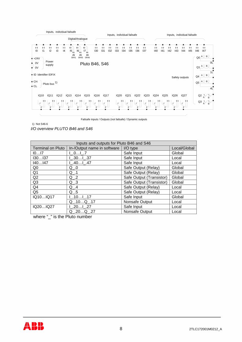
Inputs and outputs for Pluto B46 and S46 Terminal on Pluto In-/Output name in software I/O type Local/Global I0…I7 I_.0…I_.7 Safe Input Global I30…I37 I_.30…I_.37 Safe Input Local I40…I47 I_.40…I_.47 Safe Input Local Q0 Q_.0 Safe Output (Relay) Global Q1 Q_.1 Safe Output (Relay) Global Q2 Q_.2 Safe Output (Transistor) Global Q3 Q_.3 Safe Output (Transistor) Global Q4 Q_.4 Safe Output (Relay) Local Q5 Q_.5 Safe Output (Relay) Local IQ10…IQ17 I_.10…I_.17 Safe Input Global
Q_.10…Q_.17 Nonsafe Output Local IQ20…IQ27 I_.20…I_.27 Safe Input Local
Q_.20…Q_.27 Nonsafe Output Local where “_” is the Pluto number
Failsafe inputs / Outputs (not failsafe) / Dynamic outputs
IQ10 IQ11
supplyPower
+24V
IQ12 IQ13
Identifier IDFIX
IQ15IQ14 IQ16
I30
B
Inputs, individual failsafe
Q0
IQ17
I31 I32 I33 I34 I35 I36
Q2A
I37
Pluto B46, S46
Pluto bus
I45I40 I41 I42 I43 I44 I46 I47
Inputs, individual failsafe
I0 I1 I2 I3 I6I5I4 I7
IQ21IQ20 IQ25IQ24IQ23IQ22 IQ27IQ26
BA
AQ1 B
AQ4 B
Q5 A B
Q3BA
0V
0V
ID
CH
CL1)
1) Not S46-6
AI AI AISR46SR45SR41
4L
1L
0L
Safety outputs
Digital/AnalogueInputs, individual failsafe
I/O overview PLUTO B46 and S46

9 2TLC172001M0212_A
Inputs and outputs for Pluto D45 Terminal on Pluto In-/Output name in software I/O type Local/Global IA0…IA3 I_.0…I_.3 Safe Input/
Safe Analogue input 4-20mA/0-10V/ Counter input
Global
IA4…IA7 I_.4…I_.7 Safe Input/ Safe Analogue input 4-20mA/0-10V
Global
I30…I37 I_.30…I_.37 Safe Input Local I40…I47 I_.40…I_.47 Safe Input Local Q0 Q_.0 Safe Output (Relay) Global Q1 Q_.1 Safe Output (Relay) Global Q2 Q_.2 Safe Output (Transistor) Global Q3 Q_.3 Safe Output (Transistor) Global Q4 Q_.4 Safe Output (Relay) Local Q5 Q_.5 Safe Output (Relay) Local IQ10…IQ17 I_.10…I_.17 Safe Input Global
Q_.10…Q_.17 Nonsafe Output Local IQ20…IQ26 I_.20…I_.26 Safe Input Local
Q_.20…Q_.26 Nonsafe Output Local where “_” is the Pluto number
Failsafe inputs / Outputs (not failsafe) / Dynamic outputs
IQ10 IQ11
supplyPower
+24V
IQ12 IQ13
Identifier IDFIX
IQ15IQ14 IQ16
I30
B
Inputs, individual failsafe
Q0
IQ17
I31 I32 I33 I34 I35 I36
Q2A
I37
Pluto D45
Pluto bus
I45I40 I41 I42 I43 I44 I46
Digital inputs, individual failsafe
IQ21IQ20 IQ25IQ24IQ23IQ22 IQ26
BA
AQ1 B
AQ4 B
Q5 A B
Q3BA
0V
0V
ID
CH
CL
AI
4L
1L
0L
Safety outputs
Analogue inputs 0-10V/4-20mAInputs, individual failsafe
DIIA7
DI AIIA6
DI AIIA5
DI AIIA4
DI AIIA2
DI AIIA1
DI AIIA0
AIDIIA3
CS (Shield)
Fast counter
I47
I/O overview PLUTO D45

10 2TLC172001M0212_A
Inputs and outputs for Pluto B42 AS-i Terminal on Pluto In-/Output name in software I/O type Local/Global I0…I3 I_.0…I_.3 Safe Input Global I30…I37 I_.30…I_.37 Safe Input Local I40…I47 I_.40…I_.47 Safe Input Local Q0 Q_.0 Safe Output (Relay) Local Q1 Q_.1 Safe Output (Relay) Local Q2 Q_.2 Safe Output (Transistor) Local Q3 Q_.3 Safe Output (Transistor) Local Q4 Q_.4 Safe Output (Relay) Local Q5 Q_.5 Safe Output (Relay) Local IQ10…IQ17 I_.10…I_.17 Safe Input Local
Q_.10…Q_.17 Nonsafe Output Local IQ20…IQ27 I_.20…I_.27 Safe Input Local
Q_.20…Q_.27 Nonsafe Output Local ASi+ - AS-i bus - ASi-
where “_” is the Pluto number
IQ25IQ24IQ23IQ22 IQ27IQ26
BA
AQ1 B
AQ4 B
Q5 A B
Q3BA
0V
0V
ID
CH
CL
AI AI AISR46SR45SR41
4L
1L
0L
Failsafe inputs / Outputs (not failsafe) / Dynamic outputs
Power
Identifier IDFIX
Inputs, individual failsafe
Pluto bus
Inputs, individual failsafe
Safety outputs
Digital/AnalogueInputs, individual failsafe
supply
CS
AS-Interface
(Shield)
I35 I36
Q2A
I37
Pluto B42 AS-i
I45I40 I41 I42 I43 I44 I46 I47ASi+ ASi- I2I1I0 I3
IQ21IQ20IQ10 IQ11
+24V
IQ12 IQ13 IQ15IQ14 IQ16
I30
B
Q0
IQ17
I31 I32 I33 I34
I/O overview PLUTO B42 AS-i
11 2TLC172001M0212_A
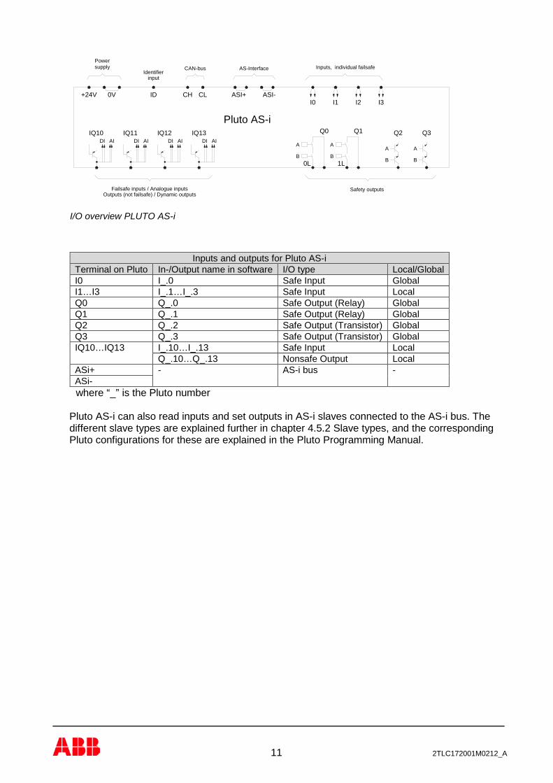
Inputs and outputs for Pluto AS-i Terminal on Pluto In-/Output name in software I/O type Local/Global I0 I_.0 Safe Input Global I1…I3 I_.1…I_.3 Safe Input Local Q0 Q_.0 Safe Output (Relay) Global Q1 Q_.1 Safe Output (Relay) Global Q2 Q_.2 Safe Output (Transistor) Global Q3 Q_.3 Safe Output (Transistor) Global IQ10…IQ13 I_.10…I_.13 Safe Input Local
Q_.10…Q_.13 Nonsafe Output Local ASi+ - AS-i bus - ASi-
where “_” is the Pluto number
Pluto AS-i can also read inputs and set outputs in AS-i slaves connected to the AS-i bus. The different slave types are explained further in chapter 4.5.2 Slave types, and the corresponding Pluto configurations for these are explained in the Pluto Programming Manual.
ASI-
IQ11 IQ12 IQ13IQ10
Outputs (not failsafe) / Dynamic outputs
DI
Failsafe inputs / Analogue inputs
AIAI DI DI AI DI AI
Powersupply
+24V CH
CAN-bus
input
0V ID
Identifier
Pluto AS-i
CL ASI+
AS-Interface
Q3Q2Q1Q0
Safety outputs
0L
A
B1L
A
BB
A
B
A
I2
Inputs, individual failsafe
I0 I1 I3
I/O overview PLUTO AS-i

12 2TLC172001M0212_A
Inputs and outputs for Pluto O2 Terminal on Pluto In-/Output name in software I/O type Local/Global I0, I1 I_.0, I_.1 Safe Input (for monitoring) Global Q0.13…Q0.34 Q_.0 Safe Output (Relay) Global Q1.13…Q0.34 Q_.1 Safe Output (Relay) Global IQ10, IQ11 I_.10, I_.11 Safe Input Global
Q_.10, Q_.11 Nonsafe Output Local where “_” is the Pluto number Pluto O2 is a safety output module with two relay output groups with three contacts each. Pluto O2 is also equipped with two safe inputs for monitoring and two combined safe in-/non-safe outputs (IQ).
4.1 I.. Digital failsafe inputs Each input is separately connected to both processors which, facilitating both single channel and dual channel safety devices.
The inputs can be supplied by +24V or by the dynamic signal outputs A, B or C.
CLI0
CH
ID
Pluto O2
IQ10
Q1
B
IQ11
33
A
13 14+24V 0V
CSh
23 2434
B33 34 13 14 23 24
A
Q0
I1
250VAC, 5A24V, 1.5A
24V, 1.5A 250VAC, 5A
Power supply
Safety Output Module
Safe inputs
Non-safe outpDynamic outp
Safe inputs
Non-safe outpDynamic outp
I/O overview PLUTO O2
13 2TLC172001M0212_A
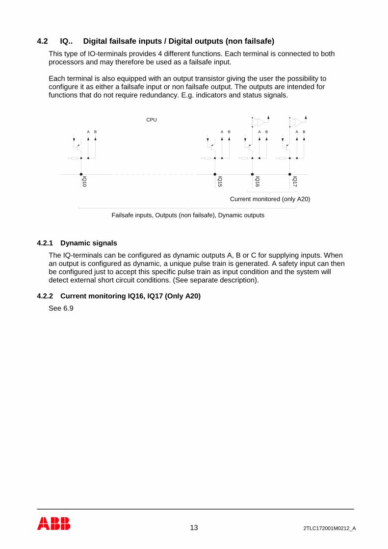
4.2 IQ.. Digital failsafe inputs / Digital outputs (non failsafe) This type of IO-terminals provides 4 different functions. Each terminal is connected to both processors and may therefore be used as a failsafe input. Each terminal is also equipped with an output transistor giving the user the possibility to configure it as either a failsafe input or non failsafe output. The outputs are intended for functions that do not require redundancy. E.g. indicators and status signals.
4.2.1 Dynamic signals The IQ-terminals can be configured as dynamic outputs A, B or C for supplying inputs. When an output is configured as dynamic, a unique pulse train is generated. A safety input can then be configured just to accept this specific pulse train as input condition and the system will detect external short circuit conditions. (See separate description).
4.2.2 Current monitoring IQ16, IQ17 (Only A20) See 6.9
Failsafe inputs, Outputs (non failsafe), Dynamic outputs
IQ10
BA
CPU
Current monitored (only A20)
IQ15
IQ16
IQ17
A B A B A B
14 2TLC172001M0212_A
4.3 Analogue inputs
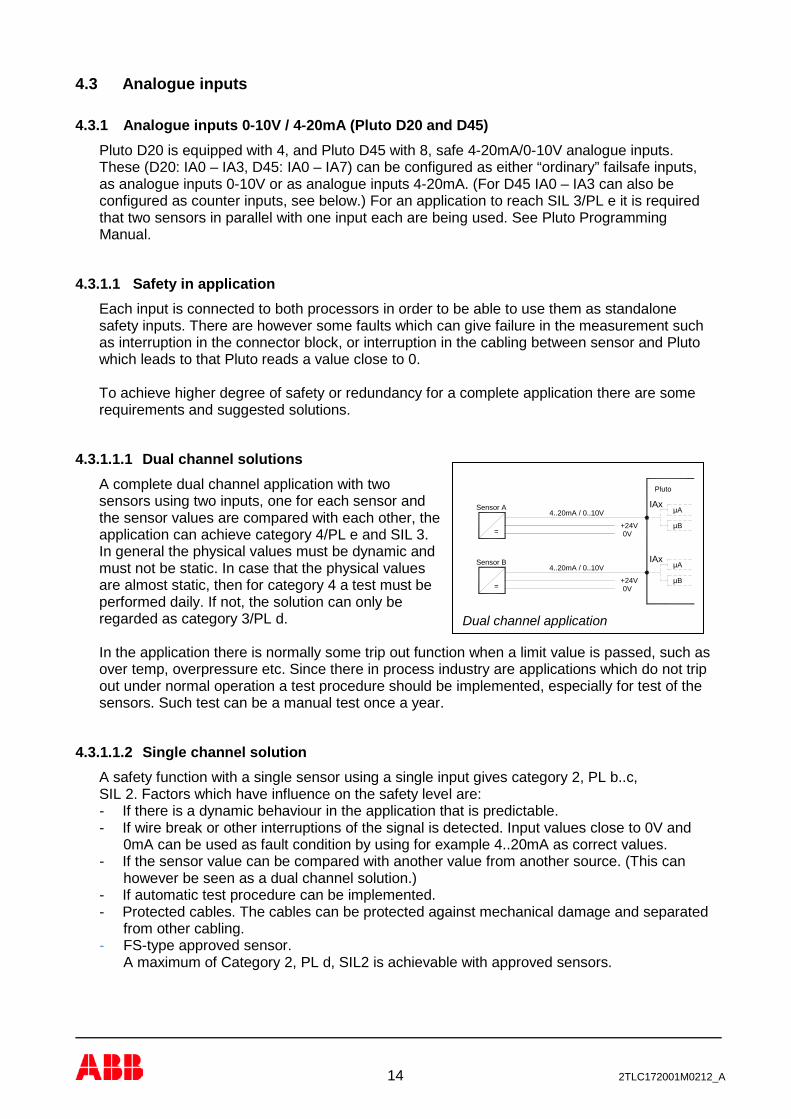
4.3.1 Analogue inputs 0-10V / 4-20mA (Pluto D20 and D45) Pluto D20 is equipped with 4, and Pluto D45 with 8, safe 4-20mA/0-10V analogue inputs. These (D20: IA0 – IA3, D45: IA0 – IA7) can be configured as either “ordinary” failsafe inputs, as analogue inputs 0-10V or as analogue inputs 4-20mA. (For D45 IA0 – IA3 can also be configured as counter inputs, see below.) For an application to reach SIL 3/PL e it is required that two sensors in parallel with one input each are being used. See Pluto Programming Manual.
4.3.1.1 Safety in application Each input is connected to both processors in order to be able to use them as standalone safety inputs. There are however some faults which can give failure in the measurement such as interruption in the connector block, or interruption in the cabling between sensor and Pluto which leads to that Pluto reads a value close to 0. To achieve higher degree of safety or redundancy for a complete application there are some requirements and suggested solutions.
4.3.1.1.1 Dual channel solutions A complete dual channel application with two sensors using two inputs, one for each sensor and the sensor values are compared with each other, the application can achieve category 4/PL e and SIL 3. In general the physical values must be dynamic and must not be static. In case that the physical values are almost static, then for category 4 a test must be performed daily. If not, the solution can only be regarded as category 3/PL d. In the application there is normally some trip out function when a limit value is passed, such as over temp, overpressure etc. Since there in process industry are applications which do not trip out under normal operation a test procedure should be implemented, especially for test of the sensors. Such test can be a manual test once a year.
4.3.1.1.2 Single channel solution A safety function with a single sensor using a single input gives category 2, PL b..c, SIL 2. Factors which have influence on the safety level are: - If there is a dynamic behaviour in the application that is predictable. - If wire break or other interruptions of the signal is detected. Input values close to 0V and
0mA can be used as fault condition by using for example 4..20mA as correct values. - If the sensor value can be compared with another value from another source. (This can
however be seen as a dual channel solution.) - If automatic test procedure can be implemented. - Protected cables. The cables can be protected against mechanical damage and separated
from other cabling. - FS-type approved sensor.
A maximum of Category 2, PL d, SIL2 is achievable with approved sensors.
Sensor B IAx
+24V0V
µB
µA
Pluto
0V+24V
IAx
µB
µA
=
4..20mA / 0..10V
4..20mA / 0..10V
=
Sensor A
Dual channel application

15 2TLC172001M0212_A
4.3.1.2 0 Volt In general 0 or close to 0 volt/mA cannot be trusted as a true signal except when there is a dynamic behaviour in the application which makes it possible to evaluate the correctness. There are two reasons for this: - 0 can be a consequence of an internal fault in Pluto. Variables in the PLC code are then
often set to 0. - An analogue value close to 0, 0..0.5V/ 0..0.5mA can be caused by wire break or other
interruption of the connected sensor. The use of 4-20mA or 2-10V range is therefore recommended.
Note: If 0-signals are used the evaluation of the correctness must be performed by the application program.
4.3.2 Possible architectures, achievable safety levels and prerequisites This table is an overview of safety levels for different applications. The achievable SIL / PL depend on the sensor which is used in the application.
Structure Achievable SIL / PL
Prerequisites, necessary diagnostic to be realized in the application program
1 standard sensor SIL 1 / PL c Measurement values < 3.0mA resp. < 1.5V have to be handled as failure conditions (DC ≥ 60%)
1 FS certified sensor (SIL 2 / PL d)
SIL 2 / PL d Measurement values < 3.0mA resp. < 1.5V have to be handled as failure conditions. Eventual additional diagnostic measures mentioned in the safety manual of the sensor
1 FS certified sensor (SIL 3 / PL e)
SIL 2 / PL d Measurement values < 3.0mA resp. < 1.5V have to be handled as failure conditions. Eventual additional diagnostic measures mentioned in the safety manual of the sensor
2 standard sensors (homogeneous redundant)
SIL 2..3 / PL d Measurement values < 3.0mA resp. < 1.5V have to be handled as failure conditions. Monitoring, if the measured values of both channels match together (DC ≥ 60%)
2 standard sensors (diverse redundant)
SIL 3 / PL e Measurement values < 3.0mA resp. < 1.5V have to be handled as failure conditions. Monitoring, if the measured values of both channels match together (DC ≥ 90%)

16 2TLC172001M0212_A
4.3.2.1 Connection of analogue voltage output sensors (0-10V) It is important that the 0V wire from the analogue sensor is connected directly to the terminal ”0V” on Pluto, and not to 0V somewhere else. Otherwise current in the 0V conductor may affect the measured analogue value.
When using long cables from the analogue sensor, a current output sensor is to be preferred over a voltage output sensor since long cables may cause a voltage drop. A current loop (4-20 mA) is not affected by this.
4.3.3 Analogue inputs (0 – 27V) Depending on type there are one or more analogue inputs. These inputs are connected to terminals for digital inputs (example A20 – I5, B46 – I5, I6, I7). These analogue inputs are read by both processors and can therefore be used for safety applications. In the PLC program the value can be read in system registers. See Pluto Programming Manual.
0V +24V
IA0
+24V
IA1 IA2..........
Pluto D20/D45
Sensor
Output
0V Signal
0V
+24V
0V
0..10V
0..10V
Sensor with 0-10V output. 0V supply to the sensor should be directly connected to Pluto 0V.
17 2TLC172001M0212_A
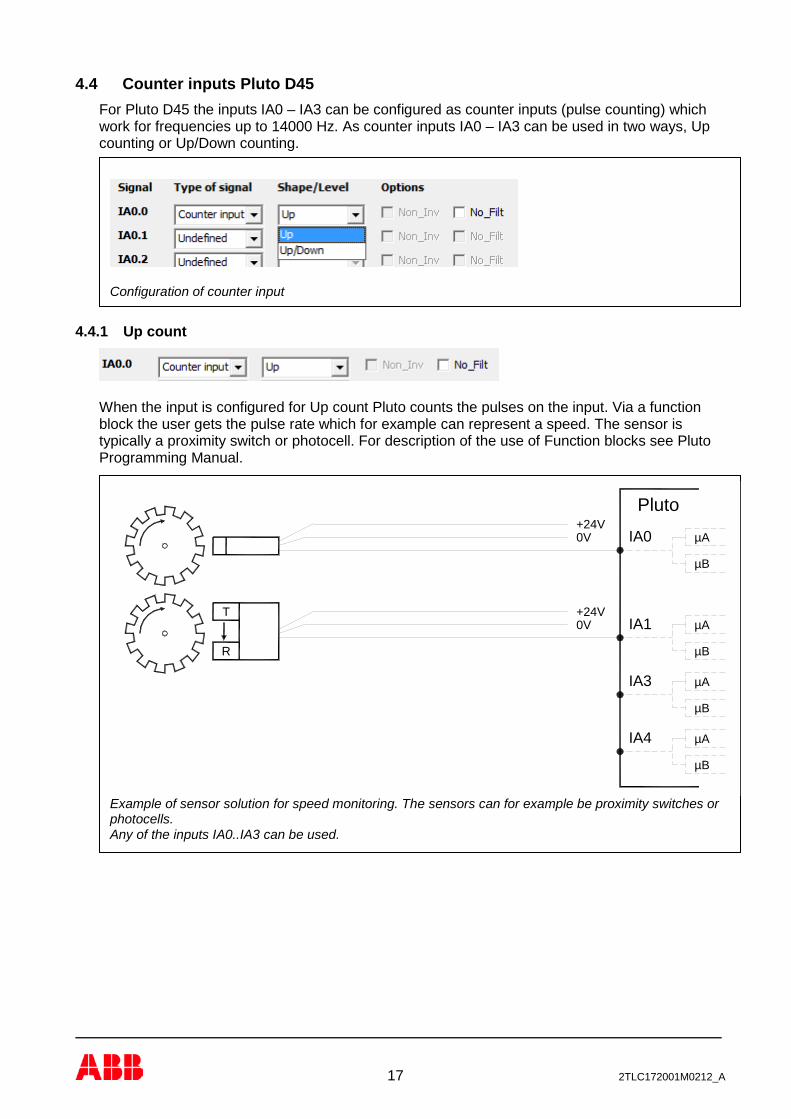
4.4 Counter inputs Pluto D45 For Pluto D45 the inputs IA0 – IA3 can be configured as counter inputs (pulse counting) which work for frequencies up to 14000 Hz. As counter inputs IA0 – IA3 can be used in two ways, Up counting or Up/Down counting.
4.4.1 Up count
When the input is configured for Up count Pluto counts the pulses on the input. Via a function block the user gets the pulse rate which for example can represent a speed. The sensor is typically a proximity switch or photocell. For description of the use of Function blocks see Pluto Programming Manual.
IA0 µA
µB
+24VPluto
IA4
µB
µB
µA
IA1
IA3 µA
µA
µB
0V
+24V0V
T
R
Example of sensor solution for speed monitoring. The sensors can for example be proximity switches or photocells. Any of the inputs IA0..IA3 can be used.
Configuration of counter input

18 2TLC172001M0212_A
4.4.2 Up/Down count
In order to determine the direction of a movement input IA0 and IA2 can be configured as Up/Down counters. When this is done the next input (IA1 or IA3) is automatically reserved for Up/Down counting. This means that for Up/Down counting IA0-IA1 are a pair and IA2-IA3 are another pair. In order to make up/down counting it requires that the sensors can produce A/B-pulses. A/B-pulses are two square wave signals that are 90° phase shifted to each other. The sensor is typically a incremental encoder 24V, HTL. For description of the use of Function blocks see Pluto Programming Manual.
Typical devices are rotary incremental encoders, 24V (HTL).
A
B
Illustration of A and B pulses. A and B are 90° phase shifted
0V
+24V
IA0
µB
µA
IA1 µA
µB
A
B
A
B
µB
IA3
IA2
+24V
0VµA
µB
µA
Pluto
Example of speed monitoring with incremental encoders leaving A and B pulses to two inputs, IA0-IA1 or IA2-IA3. The direction is then possible to measure. Two encoders with two inputs each are used in this example to achieve redundancy. For overspeed monitoring (safe low speed, SLS) category 4 and PL e is normally reached. For stand still monitoring Category 3 and PL d can be reached depending on application.

19 2TLC172001M0212_A
4.4.3 Sensor output types
Incremental encoders with HTL output and other with push-pull output can be used at frequencies up to around 14 kHz. For sensors with “open collector”, “PNP” output, or other output not of “push-pull” type the maximum frequency might typically be 1 – 4 kHz, but the limit is dependent on the output resistance, the cable length etc. The reason for this is that the signal will not have time to return to zero at higher frequencies. This will be interpreted by Pluto and the function block as Speed=0.
4.4.4 “No Filt” settings for counters For incremental encoders with HTL output and frequencies over 4 kHz the setting “No Filt” shall be selected. For lower frequencies and use of for example standard proximity switches the option “No Filt” shall not be selected since the filter will give protection against disturbances.
4.4.5 Speed monitoring with two sensors Overspeed, Safe low speed etc. With a two-channel solution where 2 sensors monitor that the speed are within certain limits the application can reach Category 3/PL d or 4/PL e if diverse types of sensors are used. As long as there is a speed the two sensors can be compared with each other and if one fails it is detected since they need to be equal. Stand still monitoring, dual channel For stand still monitoring with two sensors Category 3/PL d can be achieved. This requires however that motion is detected regularly so that the application is tested. A typical solution is every time a motion in a machine is started the PLC program requires a corresponding reaction from the sensors / speed sources. Note that in machines vibrations can cause indication of small speed values.
10V
0
1 1
0
10V
0V
+24V
Output
Sensor output Signal at low frequency Signal at too high frequency (Pluto reads 0 speed.) Signal behaviour for sensor outputs with no active pull to 0V.
0V
+24V
+24V
0V
Push-pull / HTL sensor output. Open collector / PNP sensor output Typical for incremental encoders Typical for proximity sensors and photocells
20 2TLC172001M0212_A
Interruption in the cabling to a sensor will lead to that Pluto read 0-speed from that sensor. Such fault must therefore be detected in the application by using two independent sensors that are automatically cyclically checked with regard to that there is motion in the machine at least a couple of times per day. Note: By use of two encoders which are compared with each other, faults in one sensor are monitored. The encoder can normally be of same type since the same fault in the two sensors in the same time is unlikely. But to get even higher degree of safety two of different type can be used in order to achieve diversity. This diversity minimises the risk of common cause failures.
4.4.6 Speed monitoring with one sensor Overspeed, Safe low speed etc. With a single sensor normally Category 2/PL c is reached. However, by monitoring of dynamic behaviour in the application it is possible to reach Category 3/PL d. Such monitoring for safe low speed monitoring (SLS) can be: 1) When the motion in the machine is stopped Pluto checks that the sensor also indicates a
stop. Then when the motion is started the program checks that the sensor value changes from indicating stop to the expected speed.
2) Another solution is to compare the sensor value with for example a feed back from another system such as frequency converter. The independent source of the speed information must be proven.
Stand still monitoring, single channel For stand still monitoring with one sensor Category 2/PL c can be achieved under the requirement that the sensor application is automatically cyclically tested. The interval is typically several times a day. One solution for testing is to read the speed value at every cycle start and stop of the machine cycle. Every time a motion in a machine is started the PLC program requires a corresponding reaction from the sensor. At start the program can check that the sensor value changes from stand still to an expected speed within a certain time. At stop command the program can check that the speed value decreases down to stand still. NOTE: Interruption in the cabling to a sensor will lead to that Pluto reads 0-speed. At stand still monitoring this is loss of safety function if it happens during a stop. (This is however according to the definition of category 2.)

21 2TLC172001M0212_A
Example with two incremental encoders.
Example of two channel solution with one encoder and a second channel from a frequency converter. (Cat 3/PL d/SIL 2)
4.4.7 Possible architectures, achievable safety levels and prerequisites
This table is an overview of safety levels for different applications. The achievable Cat / SIL / PL depends on the sensor which is used in the application and the detection capability of faults listed in IEC 61800-5-2, table D.8.
Structure Usage Achievable Cat/ PL/ SIL
Prerequisites, necessary diagnostic to be realized in the application program
1 sensor/encoder Overspeed Cat 2 / PL c SIL 1
Monitoring of dynamic behavior. (E.g. Stand still is off at expected movement)
Stand still monitoring
Cat 2 / PL c SIL 1
Monitoring of dynamic behavior. Stand still should not last in more than approx. 1 hour
2 sensors/encoders homogeneous redundant
Overspeed Cat 3 / PL d SIL 3
Monitoring of dynamic behavior. (E.g. Stand still is off at expected movement)
Stand still monitoring
Cat 3 / PL d SIL 2
Monitoring of dynamic behavior. Stand still should not last in more than approx. 1 hour
2 sensors/encoders diverse redundant
Overspeed Cat 4 / PL e SIL 3
Monitoring of dynamic behavior. (E.g. Stand still is off at expected movement)
Stand still monitoring
Cat 3 / PL d SIL 2
Monitoring of dynamic behavior. Stand still should not last in more than approx. 1 hour
4.4.7.1 Application examples

22 2TLC172001M0212_A
4.5 Failsafe outputs
4.5.1 Relay outputs Each potential free relay output is made individually “redundant” by the use of two series connected relay contacts controlled by each processor. A single output can be used to individually control a safety function, however the outputs cannot detect short circuits in e.g. connection cables. In addition to the output relays being controlled by separate processors the power to the relay coils are generated by “charge” pumps. (For description of function of “charge” pump see section on failsafe solid state outputs).
4.5.2 Solid state safety outputs Each digital failsafe output is individually safe and can therefore be used to individually control a safety function. The nominal output voltage is –24V DC. The negative potential is due to the “charge” pump principle used. The “charge pump” is designed in such a way that the output voltage is generated by a capacitor which is charged and discharged by two transistors. The transistors switch alternately. One transistor switches to plus potential (+), charges the capacitor and then switches off. The other transistor then switches on discharging the capacitor to 0 Volts. During the discharge phase the capacitor “sucks” current from the output making the output a negative voltage. This design principle requires that all components work and change state in the correct phase. A fault in any component leads to an immediate cessation of output current generation. An advantage of using a negative output potential is that it is not normally present in a control system. Since the output is monitored, Pluto can detect short circuit between the output and a foreign potential.
Principle for relay outputs

23 2TLC172001M0212_A
4.5.2.1 Test pulses In order to make internal tests and to test against external short circuits the outputs Q2 and Q3 are cyclically switched off during 100..200 µs, so called test pulses.
4.5.2.1.1 Disabling of test pulses For Pluto A20 v2, B20 v2, S20 v2 and Pluto D20, the test pulses can be disabled via Pluto Manager. See Pluto Programming Manual.
4.5.2.1.2 Using Pluto safety outputs Q2 and Q3 for ABB AF contactors ABB AF and AFZ contactors are different from conventional DC contactors since they have integrated electronics, making the characteristic different. From a Pluto perspective the main differences are: 1) The contactors are a bit capacitive, which affects the test pulses generated by the outputs
and causes Er40 in Pluto. To avoid this, a diode must be mounted in series with the contactor coil. The diode shall be placed close to the contactor in order to maintain the short circuit protection of the cable. An example for solution is to use ABB terminal block with diode ZS4-D-CH-DU, 1SNK505215R0000 (includes diode 1N4007). In Pluto A20 v2, B20 v2 and S20 v2 the test pulses can be disabled in the software. The diode is then not needed anymore, but note that the conductor is then not monitored against short circuits by Pluto.
2) A high inrush current when switch on which has been causing that the current limit for the outputs has been exceeded and Pluto showed ER41.
But from software version OS 3.4.1 the current limit is changed so that it can be exceeded during the first 250 ms after the output is switched on. We have tested with AF38-.. contactors and we can then recommend to load Q2 or Q3 with max two (2) of these contactors. Note: Since the higher allowed current limit is only at switch on, contacts or other interrupting components between output and load should be avoided. AFZ is a version of the AF contactor intended for PLC:s. The main difference is that the inrush current is lower than for AF. The capacitive effect is however the same so diode is needed in both cases.
Principle for solid state safety outputs. Diagram showing output voltage with test pulses

24 2TLC172001M0212_A

25 2TLC172001M0212_A
4.6 AS-Interface bus (AS-i) Only for Pluto AS-i and B42 AS-i As can be seen in the I/O overview Pluto AS-i has only 8 digital I/O but is equipped with connection for AS-i bus. AS-i is a standardised industrial bus where both power and data is transmitted via a two-wire cable. There are two organisations for the standardisation of AS-i, AS-International Association for the general specification and the consortium “Safety At Work” (SAW) for the safety protocol. This manual does only explain how Pluto AS-i can be used. General information about the AS-i bus is available at http://www.as-interface.net/, and in literature as “AS-Interface, The Automation Solution”.
4.6.1 AS-i connection It is recommended to only use two of the four AS-i terminals on Pluto. Connect all AS-i + wires to the same AS-i + terminal, and all AS-i – wires to the same AS-i – terminal. (If all four connections are used, the AS-i circuit will be broken when the terminal block is detached,)
Pluto Bus(To other Pluto units)
Pluto
SafetyE-stop
Bus Master /Monitor only /Monitor/slave
Q2I6 IQ10
Q3IQ11I7I5
I3I1C H
I2C L I0 I4
+24VID 0VIQ17IQ15IQ13
IQ12 IQ14 IQ16 Q0 Q1
PLUTOK
Q2I6 IQ10
Q3IQ11I7I5
I3I1C H
I2C L I0 I4
+24VID 0VIQ17IQ15IQ13
(30VDC)
External master(Optional)
Pluto AS-i
AS-i bus
1-channelSafetymodule
Safetyswitch 2-channel
Safetymodule
Safetylight curtain
Non-safestandard
slave
max4in/4out
Non-safe extended
slaves (A/B)
max4in/3out
A
B
AS-iPower
IQ12 IQ14 IQ16 Q0 Q1
PLUTOK
Pluto on AS-i bus with some examples of AS-i slave types.
(Note: For old Pluto AS-i, of version 1, extended non-safety slaves can only be handled in” Monitor only” mode)

26 2TLC172001M0212_A
4.6.2 Reading safety slaves The main intention with Pluto AS-i is to read and evaluate the safety slaves with its dual CPU. A standard slave can have 4 input variables which are read separately by the master. A safety slave has also 4 input variables, but physically only one single channel or dual channel input. The 4 input variables are used to send a safety code, unique for each slave. The safety code is transmitted in 8 cycles. Pluto reads the safety code, compares it with the code stored in the memory and if they match the input in the safety slave is evaluated as on (1). A teaching procedure must be performed at installation and exchange of safety slaves in order to teach Pluto the correct code for each safety slave. (See programming manual.)
4.6.3 Slave types Pluto has to be configured for the type of slave(s) that is connected to the AS-i bus. This configuration is done in Pluto Manager and is explained in the Pluto_Programming_Manual. Below is a short description of the different slave types that Pluto supports: Safe Input This is a safe slave with a single or dual channel input. For the dual channel type there is physically a dual channel input to the slave, but in Pluto/Pluto Manager it is configured as one input. The slave can also have up to 4 non-safe outputs. AS-i profile: S-x.B where x depends on I/O configuration. Nonsafe standard slaves A non-safe standard slave can have up to 4 non-safe inputs and/or up to 4 non-safe outputs. In Pluto both inputs and outputs are local. AS-i profile: S-x.F where x depends on I/O configuration. Nonsafe A/B slaves Two A/B-slaves (one A-slave + one B-slave) share the same address number. This means that up to 62 A/B-slaves can be used in a net, instead of 31 which is the maximum number for other slave types. A non-safe A/B-slave can have up to 4 inputs and/or up to 3 outputs. In Pluto both inputs and outputs are local. AS-i profile: S-x.A where x depends on I/O configuration. Combined Transaction A/B slaves Pluto supports Combined Transaction slaves with 4 inputs and 4 outputs. AS-i profile: S-7.A.7 Analogue input slaves This is a non-safe analogue input slave which can have up to 4 input channels. Pluto supports Analogue slaves with AS-i profile: S-7.3.x where x can be C…F depending on number of channels. C = 1 channel, D = 2 channels, E = 4 channels, F = 4 channels.
Analogue output slaves This is a non-safe analogue output slave which can have up to 4 output channels. Maximum 8 analogue output slaves are allowed in a project. Pluto supports Analogue slaves with AS-i profile: S-7.3.x where x can be 4…6 depending on number of channels. 4 = 1 channel, 5 = 2 channels, 6 = 4 channels.
Safe Output A safe slave has (at this moment) one safe output, and a special function block is needed for the PLC program. This slave is usually combined with a non-safe slave for feedback status. Even if this non-safe slave is included in the same housing as the safe output slave they have different addresses and they are treated as two separate slaves by Pluto. Pluto can handle up to 16 “PlutoAsSafeInput” + “SafeOutput“ slaves.

27 2TLC172001M0212_A
Pluto as Safe Input This is the setting for a Pluto that is used as a safe input slave. A special function block, “PlutoAsSafeInput”, is needed for the PLC program. Configuration of the safe input and non-safe outputs are the same as for the ordinary “Safe input” slave. Pluto can handle up to 16 “PlutoAsSafeInput” + “SafeOutput“ slaves.
4.6.4 Modes of operation Pluto has three modes of operation on the AS-i bus: Bus Master Pluto controls the AS-i bus. Via the PLC program Pluto can read the inputs and set the outputs of the slaves. Monitor only In this case Pluto only listens to the bus traffic, which is controlled by an external master. Normally this external master is a non-safety PLC system for control of the non safety related part of the application. In monitor mode Pluto can read all I/O:s on the AS-i bus but not set any outputs since it is the external master that controls the bus. Monitor / Slave This mode is the same as “Monitor only” mode but Pluto can also be a slave node under the external master. Pluto and the external master can then communicate with each other, 4 bits in each direction. AS-i profile: S-7.F
4.6.5 Exchange of Safety slaves after commissioning The system allows exchange of a safety slave without any tool for modification of the PLC program or other setup. The requirement is that all slaves, except the one that shall be replaced, are working and connected to the AS-i bus. It is also necessary that the IDFIX is of type “IDFIX-DATA” or “IDFIX-PROG”. Some AS-i units contain two AS-i addresses/slaves. For these units it is necessary to first set these two addresses to the same two addresses as in the unit it shall replace. The address can be set either with a programming tool or through Pluto Manager (Tools/AS-i/Change AS-i slave address). The procedure is as follows: - Press “K” button for 2 seconds. - If one safety slave is missing the display flashes “CC” -> “[slave number]”. - Press the “K” button one more time to acknowledge and the display will show steady “CC”. - The new safety slave can now be connected and the display will show “CF” (Code found).
(If the same slave is connected again the display will show “Cd” (Code Duplicate), which means that the code is already stored in Plutos memory.)
- By pressing “K” a last time, Pluto will automatically store the new code and reboot.
4.6.5.1 Exchange of non-safe slaves after commissioning For exchange of a non-safe slave the requirement is that all slaves, except the one that shall be replaced, are working and connected to the AS-i bus. - Remove the slave which shall be replaced. - Connect the new slave.

28 2TLC172001M0212_A
5 Connection of inputs
5.1 Dynamic signals The IQ terminals can be configured as dynamic outputs, and be used for voltage supply of the input devices. If they are configured as dynamic, each of them generates a unique pulse train as shown in the diagram below.
The system is intended for detection of different short circuits in external cabling, and dynamic monitoring of sensors. It enables the connections of devices such as “SPOT” light beams, EDEN sensors etc. that inverts the input signal. In the software a configuration of the inputs must be made to decide which kind of input signal each input shall accept as logic ”1”. Other signals that do not match with the configured signal are regarded as ”0”.
5.1.1 Connection of inputs, I.. Input type I_ can be connected to; A, B, C, A-inverse, B-inverse, C-inverse or +24V. The diagram below shows possible connections and how they are configured in the software.
NOTE: The connections are only to show how devices can be electrically connected and are not to be taken as connections for any specific applications.
Dyn A, B or C
I_
I_
I_
IQ_Configured as dynamic output
I_
I_
I_
Example of software declaration:! Q0.10, a_pulse
Configured as dynamic input, not invertedExample of software declaration:! I0.0,a_pulse, non_inv
by either inverter or inverting safety deviceExample of software declaration:! I0.0,a_pulse
Direct connection to dynamic output
Connection to dynamic input with inversion
safety device with transistor outputs.Direct connection to +24V or
! I0.0,staticExample of software declaration:
29 2TLC172001M0212_A
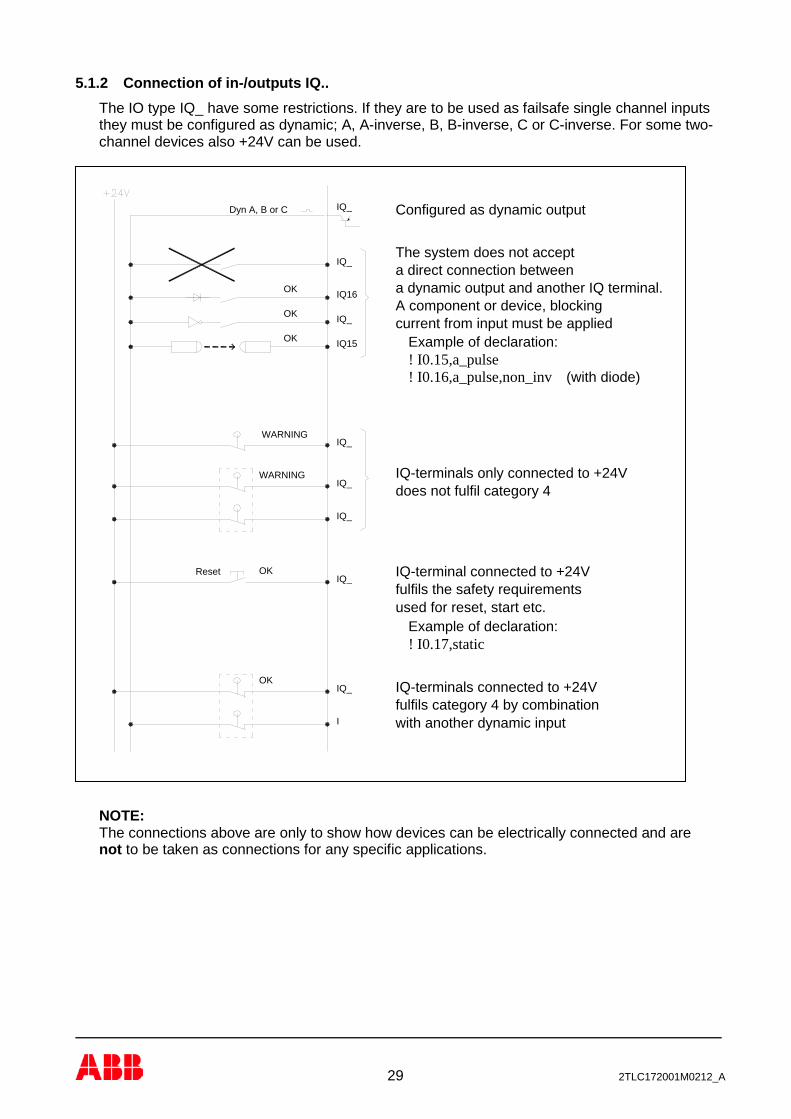
5.1.2 Connection of in-/outputs IQ.. The IO type IQ_ have some restrictions. If they are to be used as failsafe single channel inputs they must be configured as dynamic; A, A-inverse, B, B-inverse, C or C-inverse. For some two-channel devices also +24V can be used.
NOTE: The connections above are only to show how devices can be electrically connected and are not to be taken as connections for any specific applications.
WARNING
OK
I
IQ_
ResetIQ_
OK
IQ_
IQ_
WARNINGIQ_
OK
OK
OK
IQ15
IQ16
IQ_
Dyn A, B or C
IQ_
IQ_
IQ-terminals only connected to +24V
fulfils category 4 by combinationwith another dynamic input
IQ-terminals connected to +24V
does not fulfil category 4
IQ-terminal connected to +24Vfulfils the safety requirementsused for reset, start etc.
Example of declaration:! I0.17,static
(with diode)
current from input must be applied
a dynamic output and another IQ terminal.
! I0.16,a_pulse,non_inv
Example of declaration:! I0.15,a_pulse
A component or device, blocking
Configured as dynamic output
The system does not accepta direct connection between

30 2TLC172001M0212_A
6 Connection of safety devices
6.1 Dual channel systems The classic way of making a failsafe system is to use two-channel devices. The system offers various possibilities for connection of such devices. The figures below show solutions for connection of two channel devices. The first figure gives example of possible connections and the second shows the common connection of several dual channel safety devices.
Possible solutions for dual channel inputs with detection of external short circuits
A normal connection of several dual channel devices. One dynamic signal combined with static +24V.

31 2TLC172001M0212_A
6.2 Single channel systems Instead of using two-channel systems some applications can be made failsafe by using the principle of a dynamic single channel. By supplying electronic devices with dynamic signals a fault in the electronics will lead to a static on or off state at the input which will be detected immediately. By inverting the signal in or at the sensor, short circuits over the sensor are also detected.
Note: Serial connection is legal, but a short circuit of an even number of sensors is not
detected. A direct connection between two terminals of IQ type is always detected. Detection of a short circuit between an output of IQ and an input of I is not detected. See 13.1 for maximum number of sensors that can be connected in series.
6.3 Emergency stop When emergency stop functions remain inactivated for long periods of time, the function will not be monitored. It is therefore strongly recommended that emergency stop systems are periodically, manually tested and that this forms part of the maintenance instructions for the machine.
D
yn. C
Dyn
. A
Dyn
. B
IQ_IQ_
IQ_I_
IQ_
+ -
IQ_I_
IQ_I_
+ - Adam Eva

32 2TLC172001M0212_A
6.4 Monitoring of external short circuit The system offers three main methods for avoiding that short circuit in input cabling leads to loss of the safety function. The drawing below illustrates the different methods by which emergency stop buttons can be connected.
- The first button has two NC contacts supplied by one dynamic signal and +24V. The inputs are configured just to accept the expected signal and will therefore detect a short circuit between the channels as well as to other foreign voltage.
- The button in the middle has one NC and one NO contact supplied by +24V. The software
requires that the inputs operate in opposition to each other. A short circuit in the connecting cable will have the effect that both inputs will at sometime during the cycle be ON, which the system does not accept.
- The last emergency stop button uses a short circuit proof single channel technique. A
dynamic signal is converted by an inverter mounted close to the contact. The input is configured just to accept the inverted result of the supplied dynamic signal. A short circuit in the connecting cable will result in an incorrect signal being presented to the input which will not be accepted by the system.

33 2TLC172001M0212_A
6.5 Safety devices with transistor outputs Certain safety devices on the market, i.e. light curtains, light beams, scanners etc., are designed with dual monitored safety 24V DC transistor outputs. These devices monitor the output circuits by making short interruptions in the output signals. Both channels can be connected to the system as static inputs. Faults are detected by the safety device instead of by the Pluto system. But note that at least one of the inputs must be of IO-type I_. The short interruptions of the output signals are taken care of by the Pluto input filtering system.
6.6 Safety mats and safety edges Safety mats and safety edges must be supplied by two different dynamic signals and be connected to two inputs. By activation the two inputs will both get wrong input signal and give “0” in the software as result. The programming can be made in the same way as for other dual channel functions.
I0.0 I0.1
OSSD
1
OSSD
2
I0.2 IQ0.10O
SSD1
OSSD
2
I0.0, staticI0.1, static
I0.2, staticI0.10, static
IQ0.13IQ0.12
OSSD
1
OSSD
2
Declaration in software (Pluto no:0) :
NOTE: Only one of the inputs may be of the IO-type IQ_.
Connection of safety mats. The diodes shall be placed before the mat (as shown).

34 2TLC172001M0212_A
6.7 Two-hand control Two-hand control devices can be realized in many ways depending on the contact configuration in the two-hand device and which Pluto inputs are used. Below are some examples of solutions. All of the examples shown fulfil the requirements for type IIIC according to EN 574.
Dyn
+24V
Dyn
+24V
Classic two-hand Safeball
Examples of two-hand control

35 2TLC172001M0212_A
6.8 Illuminated push button function It is possible to connect both an indicator lamp and an input switch at the same time to IQ terminals, e.g. illuminated push button. A diode must be connected locally to the input device. The function is mainly intended for reset devices and reduces the number of IQ terminals used.
Note that the output voltage is a square wave of 24 V amplitude and the effective voltage to the indicator is reduced to a mean value of 75%. A filament bulb or LED designed for 24 VDC can be used.
6.9 Monitoring of muting lamp (only A20) The system can measure the current in output IQ16 and IQ17. The function is intended for monitoring the current in a muting lamp, but other usage is not excluded. As the hardware for measuring the current is not fully redundant the function must be used in a dynamic way if used for safety functions. This means that the current must be read and evaluated both when the output is switched on and off.
36 2TLC172001M0212_A
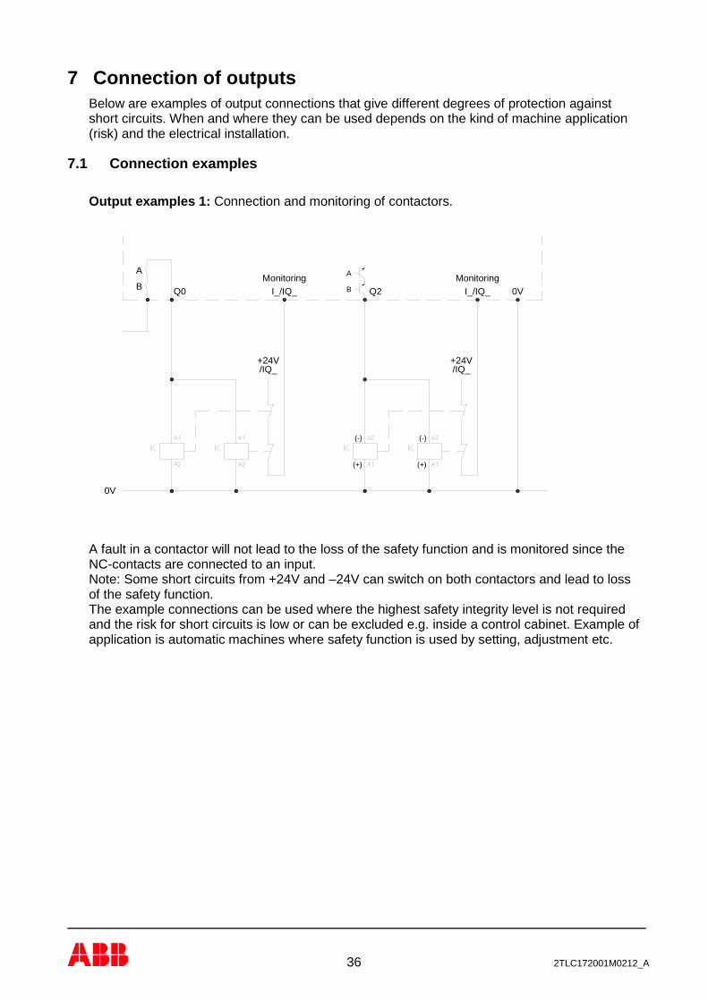
7 Connection of outputs Below are examples of output connections that give different degrees of protection against short circuits. When and where they can be used depends on the kind of machine application (risk) and the electrical installation.
7.1 Connection examples Output examples 1: Connection and monitoring of contactors.
A fault in a contactor will not lead to the loss of the safety function and is monitored since the NC-contacts are connected to an input. Note: Some short circuits from +24V and –24V can switch on both contactors and lead to loss of the safety function. The example connections can be used where the highest safety integrity level is not required and the risk for short circuits is low or can be excluded e.g. inside a control cabinet. Example of application is automatic machines where safety function is used by setting, adjustment etc.
B BQ0
A
Q2
A
+24V/IQ_ /IQ_
+24V
(+)
(-) (-)
(+)
0V
I_/IQ_ I_/IQ_ 0VMonitoring Monitoring

37 2TLC172001M0212_A
Output examples 2: Contact expansion with expansion relays and safety relay
The examples give the same degree of safety and have the same advantages and disadvantages as output examples 1 and can be used for the same type of applications. Output examples 3: Short circuit protected Connection and monitoring of contactors with protection against short circuit, for applications with very high demands on safety integrity level. (Category 4). In the example using output Q2 the conductor is protected with a shield connected to protective ground. Examples are applications for safeguarding the operator of manual operated machines like presses and press brakes.
B Q1
A
0VQ2B
AMonitoring
0V
/IQ_+24
I_/IQ_ I_/IQ_Monitoring
/IQ_+24
+24V+24V
B
A
Q0
-24V(Minus)
InA TestInB
B BQ0
A
Q3
A
/IQ_+24
0V
I_/IQ_ 0VI_/IQ_Q2
+24/IQ_
(+)
(-)
(+)
(-)
A
BMonitoring Monitoring
Q1
A
B
U
I_/IQ_Q2
(+)
(-)
(+)
(-)
/IQ_+24
B
AMonitoring

38 2TLC172001M0212_A
Output example 4: Polarized safety relays
InA TestInB
0V
Q2
A
B Q3B
AMonitoring
I_/IQ_
+24/IQ_
When using a safety relay for output expansion of output Q2 and Q3, the connection between the Pluto output and the safety relay is failsafe against short circuit from foreign +24V. This because it is operated by -24V and since the safety relay is polarized it cannot be switched on by +24V. As long as a -24V potential does not exist in the cabinet (which is not normally the case) the connection is failsafe.
39 2TLC172001M0212_A
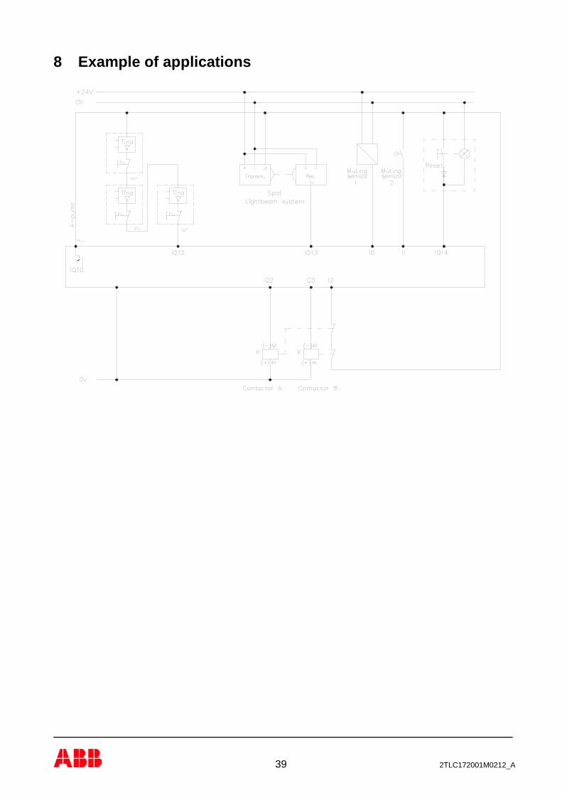
8 Example of applications

40 2TLC172001M0212_A
9 Pluto bus communication Up to 32 Pluto units can be interconnected with CAN-bus. Communication is achieved by connecting a twisted pair cable to the CH and CL terminals. When this connection is made the Pluto units can read each other’s I/O. When the bus is connected each Pluto unit executes its own individual program and operates independently, however it can read other units I/O. An interruption of the bus connection results in the I/O in the unit with which communication is lost, being regarded as a “0” condition by other units on the bus. In this situation all units will continue program execution with the consequences of the fault being dependent upon the application program. For instance, if an emergency stop button connected to one unit is used by another unit as a condition for setting an output, the output will switch off if communications are lost. Outputs generated by I/O connected directly to a unit are not affected by interruption of communications.
9.1 Bus cabling The maximum length of CAN-bus cabling is dependent on the transmission speed. At the default setting of 400 kbit/s the maximum total length is 150 meters. (This length can be extended by the use of Gateways as bridges. See Pluto Gateway Manual chapter 1 “General” and chapter 8 “CAN bridge mode”). At each end of the bus a termination resistor of 120 Ω must be installed. When a Pluto unit is working alone and no bus-cable is connected, it must still be equipped with a termination resistor. The bus connection should be made with a twisted pair cable to the CH and CL terminals.
120 Ω 120 Ω120 Ω
IQ12 IQ14 IQ16 Q0 Q1
PLUTOK
CL
CH
Q2I6 IQ10
Q3IQ11I7I5
I3I1C H
I2C L I0 I4
+24VID 0VIQ17IQ15IQ13
IQ12 IQ14 IQ16 Q0 Q1
PLUTOK
CL
CH
Q2I6 IQ10
Q3IQ11I7I5
I3I1C H
I2C L I0 I4
+24VID 0VIQ17IQ15IQ13
IQ12 IQ14 IQ16 Q0 Q1
PLUTOK
CL
CH
Q2I6 IQ10
Q3IQ11I7I5
I3I1C H
I2C L I0 I4
+24VID 0VIQ17IQ15IQ13
IQ12 IQ14 IQ16 Q0 Q1
PLUTOK
CL
CH
Q2I6 IQ10
Q3IQ11I7I5
I3I1C H
I2C L I0 I4
+24VID 0VIQ17IQ15IQ13
IQ12 IQ14 IQ16 Q0 Q1
PLUTOK
CL
CH
Q2I6 IQ10
Q3IQ11I7I5
I3I1C H
I2C L I0 I4
+24VID 0VIQ17IQ15IQ13
IQ12 IQ14 IQ16 Q0 Q1
PLUTOK
CL
CH
Q2I6 IQ10
Q3IQ11I7I5
I3I1C H
I2C L I0 I4
+24VID 0VIQ17IQ15IQ13
Stub
Connection of CAN bus: CH to CH and CL to CL. A terminating resistor in each end of the bus. Stubs are restricted to certain max length and shall not have terminating resistor.

41 2TLC172001M0212_A
9.1.1 Cable length The maximum cable length is depending on the bus speed.
Data Rate
Trunk Distance
Stub length Units connected on a Stub must not have termination resistors fitted. Max single stub Accumulated stub length
100 kbit/s 600 m 25 m 120 m 125 kbit/s 500m 20 m 100 m 200 kbit/s 300m 13 m 70 m 250 kbit/s 250m 10 m 50 m 400 kbit/s 150m 6 m 30 m 500 kbit/s 100m 5 m 25 m 800 kbit/s 50m 3 m 15 m 1 Mbit/s <20m 1 m 5 m
9.1.2 Connection of bus cable shield It is not clear which is the right solution for connection of the bus cable shield because there are different disturbances that can make influence on the system. In some cases with high disturbances it can be necessary to test different solutions. The figure below shows two alternatives. Alternative 1 is the common solution giving a god protection against disturbances along the cable but have the disadvantage in that current in the shield can appear and by noisy supply voltage to Pluto it can also give problems. Alternative 2 solves the problems with alternative 1 but does not give good protection against high frequency disturbances. If the Pluto units are mounted close to each other in the same cabinet the shield can be omitted.
Both ends connected to earth
Cabinet Cabinet
Inside cabinet
(B42 AS-i: Connect to "CS" terminal)
* or CS terminal
* or CS terminal
K K K K K
IQ13 IQ15 IQ17 0VID +24V
I4I0C L I2
C H I1 I3
I5 I7 IQ11 Q3
IQ10I6 Q2
* or CS terminal
Alternative 1
PLUTO
Q1Q0IQ16IQ14IQ12
IQ13 IQ15 IQ17 0VID +24V
I4I0C L I2
C H I1 I3
I5 I7 IQ11 Q3
IQ10I6 Q2Q2I6 IQ10
Q3IQ11I7I5
I3I1C H
I2C L I0 I4
+24VID 0VIQ17IQ15IQ13
IQ12 IQ14 IQ16 Q0 Q1
PLUTO
Alternative 2
and other end not connectedOne end to earth (B42 AS-i: Connect to "CS" terminal)
Cabinet Cabinet
PLUTO
Q1Q0IQ16IQ14IQ12
Q2I6 IQ10
Q3IQ11I7I5
I3I1C H
I2C L I0 I4
+24VID 0VIQ17IQ15IQ13
IQ12 IQ14 IQ16 Q0 Q1
PLUTO PLUTO
Q1Q0IQ16IQ14IQ12
IQ13 IQ15 IQ17 0VID +24V
I4I0C L I2
C H I1 I3
I5 I7 IQ11 Q3
IQ10I6 Q2
Alternatives for connection of bus cable shield *For B42 AS-i and D45 connect shield to the ”CS” terminal

42 2TLC172001M0212_A
9.1.3 Optional protection against conducted disturbances Conducted disturbances may cause problems with the Pluto bus communication. This problem might be solved by connecting a capacitor between 0V on Pluto Supply and earth. Please note that this connection is optional. It shall only be tried if there is a problem with the bus communication!
9.2 Response time over the bus As default the system works with the Baud rate set to 400 kbit/s and CAN-cycle to 20 ms. CAN-cycle 20 ms gives 10 ms extra response time for data over the bus (10-40 ms under fault condition). The records under Technical data for response time over bus etc. are related to this. To enable the use of longer cable lengths it is possible to change the baud rate to a lower value, but care must be taken as the bus can be overloaded. To avoid this overload there are two solutions: either to limit the amount of Pluto units connected on the bus or to increase the Bus cycle time which also increases the response time. Note that “Bus cycle time” is individually set for each Pluto unit which means that it is possible to give variables of some Pluto units, better response times than others. It is also important to note that if an input in one unit controls an output in another, it is regarding the response time only relevant where the input is located. If the “Bus cycle time” in the unit with the output is changed it has no influence on the response time. The table below is a guideline for selection of bus parameters.
Baud rate Bus cycle time
100 kb/s 125 kb/s 200 kb/s 250 kb/s 400 kb/s 500 kb/s 800 kb/s
10 ms 3..4 4..6 8..10 12..14 18..25 25..32 32 20 ms 6..8 10..14 20..32 22..32 32 32 32 30 ms 12..18 15..21 20..32 25..32 32 32 32 40 ms 12..23 20..30 28..32 30..32 32 32 32
Possible number of units connected to the bus.
NOTE 1: The exact value for number of units can not be established since it depends on the application. If I/Os in a Pluto unit changes state often it produces more CAN telegrams. NOTE 2: The prolongation of response time for I/O over the bus is equal with the Bus cycle time.
0V +24V
4-15nF
K
Q2I6 IQ10
Q3IQ11I7I5
I3I1C H
I2C L I0 I4
+24VID 0VIQ17IQ15IQ13
IQ12 IQ14 IQ16 Q0 Q1
PLUTO
Capacitor between 0V and earth.
Example of terminal block with capacitor.

43 2TLC172001M0212_A
10 Identifier The identifier is an external component that can be connected to the “ID” and “0V” terminals. The circuit contains a unique ID-number that can be read by the system. In the PLC program the identifier number can be declared which connects the program so that it will only work together with the correct identifier. The use of identifier is voluntary as long as a unit works alone, but if an identifier is connected to the unit and the PLC program is declared to work without, the program will not run. The function gives a protection against a unit being exchanged by mistake. The identifier circuit should be securely fastened to the physical location of the unit by e.g. tie it together with other connection conductors.
When a number of Pluto-units are interconnected with the bus, identifiers are necessary. The units are numbered 0…31. In the application program it is necessary to declare which identifier number has to be connected to which Pluto unit (0…31). Example: ! id_pluto:01=023474526654 There are several types of identifier circuits available; IDFIX-R (pre-programmed) - The number is programmed by the circuit manufacturer who guarantees that two circuits with
the same number do not exist. IDFIX-RW (programmable) - The number can be programmed by the user. IDFIX-DATA (programmable & data storage) - For Pluto AS-i and B42 AS-i (but works for all Pluto models). - The number can be programmed by the user and safety codes of AS-i safe slaves can be
stored. IDFIX-PROG 2k5 / IDFIX-PROG 10k (programmable, data & PLC program storage) - For Pluto with OS version 2.50 or higher (PROG 2k5), 2.52/3.2 or higher (PROG 10k). - This IDFIX has enough memory to also store the PLC program
(maximum size IDFIX-PROG 2k5: 2.3 kbyte IDFIX-PROG 10k: 10 kbyte). - Only one Pluto is allowed in the project, and the IDFIX code is always EEEEEEEEEEE0
(PROG 2k5), or EEEEEEEEEEE2 (PROG 10k). - Can be used to store AS-i safety codes in the same way as IDFIX-DATA. - When a program is downloaded to Pluto the IDFIX-PROG will automatically be updated. - If there is a difference between the program in the IDFIX-PROG and the flash memory then
Er31 will be displayed and PLC program execution is prohibited. This is checked at program download and at boot time.
BlueBlack
ID 0V
Q1Q0
IQ13 IQ15 IQ17 0VID +24V
Connection of identifier

44 2TLC172001M0212_A
- The PLC program in IDFIX-PROG can be loaded into flash memory by pressing the K button in the same way as self programming over the CAN bus. This can be done when Pluto displays error message Er20 (No program loaded), Er24 (Erroneous PLC program) or Er31 (IDFIX-PROG program mismatch).
Programmable identifiers (IDFIX-RW and IDFIX-DATA) can for example be used where it is required to deliver units with the same PLC program e.g. for a special machine or safety application.

45 2TLC172001M0212_A
11 Programming The development of application programs (Pluto PLC program) is made with a standard Personal Computer using a specially developed software Pluto Manager. Communication between the PC and the Pluto is made via the PC Com Port or USB port. The link facilitates program down loading and monitoring of inputs, outputs, memory, timers, etc. with the PC “on line”. See separate programming manual for further information.
11.1 Self programming by exchange of Pluto In applications with several Pluto units connected together with the Pluto CAN bus, it is possible to exchange a unit and let it self load PLC program from another Pluto on the bus. This is possible since in a program project with at least two Pluto units, all of them are loaded with the same program file and this file has program for all units. The following conditions are required: − The new Pluto must be empty of PLC program (showing Er20).
(Pluto O2: Error LED On with short off periods (1200/80 ms)) − The new Pluto must be member in a Pluto program project. − The IDFIX must NOT be exchanged. (Note that the connector blocks are detachable) − For Pluto AS-i the IDFIX must be of type “IDFIX-DATA” or “IDFIX-PROG”. (Otherwise the
“Teach safety codes” procedure has to be performed as well.) Procedure: − Switch off power and exchange Pluto. − Switch power on and after a few seconds the display shall show Er20 (empty).
(Pluto O2: Error LED On with short off periods (1200/80 ms)) − Press the “K” button in the Pluto front in 3 seconds until the display flashes “Lo”.
(Pluto O2: Error LED Flashes (320/320 ms)) − Release the “K” button and press it immediately one more time.
The display shall show steady “Lo”. (Pluto O2: Run LED shall be On)
− Now the self programming has started. “K” button can be released, and when it is finished Pluto starts to run automatically.
If flashing “Lo” doesn’t appear (Pluto O2: Run LED shall be On): − Check the CAN bus connection. − Check that the IDFIX is connected and that it is not changed to another with other number. − Check that the Pluto really was member in same program project as the other on the Pluto
bus.

46 2TLC172001M0212_A
12 Cleaning The front plate can be cleaned by a dry dust rag. The front plate can also be removed for cleaning or exchange.
13 Technical data Supply Nominal Voltage 24 V DC Tolerance +/-15% Max interruption 20 ms
Recommended external fuse A20, B16, B20, S20, B22, D20, Pluto AS-i, O2: 6A B46, S46, D45, B42 AS-i: 10A Total current consumption A20, B16, B20, S20, B22, D20 Pluto AS-i: 5A max B46, S46, D45, B42 AS-i: 7A max O2: 1.3 A max Own current consumption A20, B16, B20, S20, B22, D20 Pluto AS-i: 100…300 mA B46, S46, D45, B42 AS-i: 100…500 mA O2: 100 mA Electrical installation: Category II according to IEC 61010-1 Failsafe inputs (including counter inputs) I0, I1, I2, .. +24V (for PNP sensors) IQ10, IQ11, .. +24V (for PNP sensors) also configurable as non-failsafe outputs. Logic “1” > 12V Logic “0” < 8V Input current at 24V: 5.1 mA Max. over voltage 27 V continuously Analogue inputs (0-27V) Range: 0…27 V A20 family Terminal I5 Double family Terminal I5, I6 and I7 Pluto D45 Terminal I10, I11 and I12 Pluto B42 AS-i Terminal I1, I2 and I3 Pluto AS-i Terminal I10, I11, I12 and I13 Analogue inputs (IA0-IA3, IA0-IA7) Range: 0…10 V / 4...20mA D20 Terminal IA0, IA1, IA2, IA3 D45 Terminal IA0, IA1, IA2, IA3, IA4, IA5, IA6, IA7 Resolution D20 10 bits Resolution D45 12 bits Accuracy D20 ±0.75% of full scale value Accuracy D45 0 – 10V: ±0.4% of full scale value 4 – 20mA: ±0.2% of full scale value Impedance D20 0 – 10V: >10 kΩ 4 – 20mA: 420 Ω Impedance D45 0 – 10V: >10kΩ 4 – 20mA: 300 Ω Counter inputs (Pluto D45) Max frequency: 14 kHz at 50% duty cycle

47 2TLC172001M0212_A
Safety output Q2, Q3: Solid state, -24V DC, 800mA Output voltage tolerance: Supply voltage -1.5V at 800mA Q0, Q1, (Q4, Q5): Relay, AC-12: 250 V / 1.5 A AC-15: 250 V / 1.5 A DC-12: 50 V / 1.5 A DC-13: 24 V / 1.5 A Pluto O2: Q0, Q1: 13-14, 23-24 Relay, AC-12: 250 V / 5 A AC-15: 250 V / 3 A DC-12: 60 V / 5 A DC-13: 24 V / 3 A 33-34 Relay, AC-12/AC-15/DC-12/DC-13: 24 V / 1.5 A Outputs, non-failsafe IQ10, IQ11,.. Solid state +24V, PNP open collector Also configurable as failsafe inputs. Max load/output: 800 mA Max total load: A20, B16, B20, S20, B22, D20 IQ10..17: 2.5 A B46, S46, D45, B42 AS-i IQ10..17: 2 A, IQ20..27: 2A Pluto AS-i IQ10..13: 2 A Current monitoring IQ16, IQ17 (Only Pluto A20) Range 0-1.0 A Accuracy 10%
48 2TLC172001M0212_A
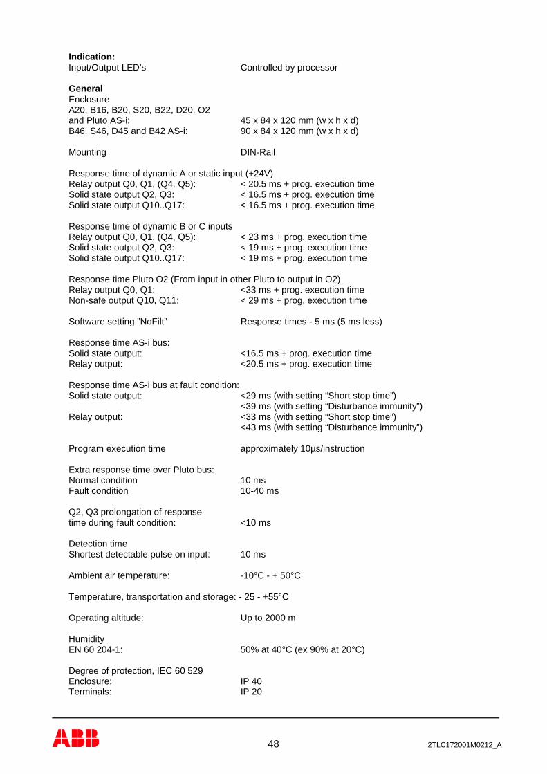
Indication: Input/Output LED’s Controlled by processor General Enclosure A20, B16, B20, S20, B22, D20, O2 and Pluto AS-i: 45 x 84 x 120 mm (w x h x d) B46, S46, D45 and B42 AS-i: 90 x 84 x 120 mm (w x h x d) Mounting DIN-Rail Response time of dynamic A or static input (+24V) Relay output Q0, Q1, (Q4, Q5): < 20.5 ms + prog. execution time Solid state output Q2, Q3: < 16.5 ms + prog. execution time Solid state output Q10..Q17: < 16.5 ms + prog. execution time Response time of dynamic B or C inputs Relay output Q0, Q1, (Q4, Q5): < 23 ms + prog. execution time Solid state output Q2, Q3: < 19 ms + prog. execution time Solid state output Q10..Q17: < 19 ms + prog. execution time Response time Pluto O2 (From input in other Pluto to output in O2) Relay output Q0, Q1: <33 ms + prog. execution time Non-safe output Q10, Q11: < 29 ms + prog. execution time Software setting ”NoFilt” Response times - 5 ms (5 ms less) Response time AS-i bus: Solid state output: <16.5 ms + prog. execution time Relay output: <20.5 ms + prog. execution time Response time AS-i bus at fault condition: Solid state output: <29 ms (with setting “Short stop time”) <39 ms (with setting “Disturbance immunity”) Relay output: <33 ms (with setting “Short stop time”) <43 ms (with setting “Disturbance immunity”) Program execution time approximately 10µs/instruction Extra response time over Pluto bus: Normal condition 10 ms Fault condition 10-40 ms Q2, Q3 prolongation of response time during fault condition: <10 ms Detection time Shortest detectable pulse on input: 10 ms Ambient air temperature: -10°C - + 50°C Temperature, transportation and storage: - 25 - +55°C Operating altitude: Up to 2000 m Humidity EN 60 204-1: 50% at 40°C (ex 90% at 20°C) Degree of protection, IEC 60 529 Enclosure: IP 40 Terminals: IP 20

49 2TLC172001M0212_A
Safety parameters SIL according to IEC 61508 SIL 3 SIL according to EN 62061 SIL CL 3 PL according to EN ISO 13849-1 PL e Category according to EN ISO 13849-1 4 DCavg according to EN ISO 13849-1 High CCF according to EN ISO 13849-1 Meets the requirements HFT (Hardware fault tolerance) 1 SFF (Safe failure fraction) >99% for the single channel parts >90% for the double channel parts Digital input to Safety output * PFDAV (for proof test interval = 20 years) 1.5 x 10⁻⁴
PFHD according to IEC 61508/EN 62061 2 x 10⁻⁹
MTTFd according to EN ISO 13849-1 High/1100 years
Analogue inputs to Safety output (Pluto D20, D45) 2 inputs/sensors (see 4.3.2) 1 input/sensor (see 4.3.2) SIL according to IEC 61508/EN 62061 Up to SIL 3 Up to SIL 2 PL according to EN ISO 13849-1 Up to PL e Up to PL d DCavg according to EN ISO 13849-1 Up to High Up to Medium PFDAV (for proof test interval = 20 years) 1.5 x 10⁻⁴ 1.5 x 10⁻³
PFHD according to IEC 61508/EN 62061 1.6 x 10⁻⁹ 5.8 x 10⁻⁹
MTTFd according to EN ISO 13849-1 High/1100 years High/400 years Counter inputs to Safety output (Pluto D45) 2 inputs/sensors (see 4.4.7) 1 input/sensor (see 4.4.7) SIL according to IEC 61508/EN 62061 Up to SIL 3 Up to SIL 1 PL according to EN ISO 13849-1 Up to PL e Up to PL c DCavg according to EN ISO 13849-1 Up to High Up to High PFDAV (for proof test interval = 20 years) 1.5 x 10⁻⁴ 1.5 x 10⁻⁴
PFHD according to IEC 61508/EN 62061 1.6 x 10⁻⁹ 1.6 x 10⁻⁹
MTTFd according to EN ISO 13849-1 High/1100 years High/1100 years Note: PFDAV = Average probability of dangerous failure on demand PFHD = Probability of dangerous failure per hour MTTFd = Mean time to dangerous failure/channel PL = Performance level (as defined in EN ISO 13849-1) CCF = Common cause failure *Input to output (incl. AS-i and CAN bus)

50 2TLC172001M0212_A
13.1 Connection of sensors Maximum number of sensors that can be connected in series with 100m cable: Eden 10 Spot 35 3 Spot 10 1 Tina 10 Maximum cable length, without sensors, for inputs using dynamic signals (depending on capacitance): Example 10x0.75 mm² = approx. 1000 meter

51 2TLC172001M0212_A
14 Appendix - Message and fault code list Note: Reboot can either be made from PC computer or by power off-on. Status messages
No: Description - - Power up
N n Run mode (nn = station number) Lo Program load mode state.
Flashing ”Lo”, ready for self programming (program found in other unit). HA
(SR11=7) Program execution stopped from PC computer or not started after program download. Can be started either from PC or by power off-on.
UE Application specific user error, controlled by SR_PlutoDisplay in the PLC program. User faults
No: Fault and possible reason. Reset action Er10* Dynamic output short circuited to foreign voltage. Automatically reset Er11* IQ_ for illuminated push button function. Missing diode. Automatically reset Er12* Short circuit between two dynamic inputs. Automatically reset Er13* Static output Q10..17 (Q20..27) short circuited to 0V or
overloaded. Automatically reset, “K” button
Er14* Static output Q10..17 (Q20..27) short circuited to 24V. Automatically reset Er15 Power supply below 18V. Autom. 3 min or ”K” button Er16 Power supply above 30V. Autom. 3 min or ”K” button Er17 Power supply below 15V. Critically low. Autom. 3 min or ”K” button Er18 CAN-bus fault. (Short circuit, termination resistor, etc.) Autom. 3 min or ”K” button Er19 Other unit with same station number on Can-bus. Er20 PLC-program not loaded. Load of PLC program Er21 PLC-program CRC-error. Reload with valid PLC-program Er22 IDFIX problem. External IDFIX can not be read. Reboot (Replace IDFIX) Er23 Unmatched ID. IDFIX doesn’t match declaration in
program. Exchange of identifiers or re-declaration of identifier in program.
Er24 Erroneous PLC-code. Invalid PLC-instructions. Reload with valid PLC-program Er25 For versions as B16 or B22. Non existing output used in
program.
Er26 Baud rate conflict. Unit programmed for other baud rate than current bus baud rate. Note that Pluto must be rebooted after change of baudrate in the PLC program.
Reprogramming or reboot
Er27 Wrong checksum for unit member in common program.
Reprogramming or reboot
Er28 PLC program does not match the Pluto family. Families: [A/B/S/D 20, 16, 22], [B/S/D 45, 46], [Pluto AS-i, B42 AS-i]
Change to other type of Pluto or change the program.
Er29 Unsupported program version. The program contains instructions only supported by later customer specific operating systems. **(See below)
Update of operating system
Er30 Unsupported function block used. **(See below) Update of operating system Er31 IDFIX-PROG program mismatch. Load program to flash memory
with ”K” button. *Combined with LED flashing for the affected I/O. **Additional information can be retrieved via Pluto Manager.

52 2TLC172001M0212_A
I/O faults No: Fault and possible reason. Reset action
Er40* Error safety output Q2 or Q3. Q2, Q3 connected together or to other negative voltage. Q2, Q3 has too high capacitive load.
“K” button
Er41* Error output Q2 or Q3. Overload or connected to foreign positive voltage.
“K” button
Er42* Error relay output. No answer from internal relay monitoring when output is off.
“K” button
Er43* Error relay output. (Self test of transistors) Reboot Er44* Error relay output. Internal relay does not switch on. “K” button Er45 Analogue functions not calibrated. System must be calibrated.
Can be reset with “K” button but analogue value will be 0.
Er46 Analogue input error. **(See below) Automatically reset Er47 Positive voltage on Q2 and/or Q3. Automatically reset
*Combined with LED flashing for the affected I/O. **Additional information can be retrieved via Pluto Manager. CPU faults
No: Fault and possible reason. Reset action Er50* Input data difference between processor A and B.
Processor A and B reads an input differently. The fault is often caused by a bad sensor.
Reboot
Er51 Output data difference between processor A and B. Processor A and B sets a global variable differently. (Q0..Q3, GM0..11). **(See below)
Reboot Check PLC-program
Er52 No answer from any internal relay when output is off. (Both relays stuck)
Reboot
Er58 AS-i safety code table CRC error. Reboot, Teach AS-i safety codes
Er59 Calibration analogue functions CRC fault. Reboot Er60 System error Twin self test monitoring. Reboot Er61 System error Timer IRQ monitoring. Reboot Er62 System error Internal serial communication. Reboot Er63 Boot-flash CRC Reboot Er64 OS-flash CRC Reboot,
Reload operating system (OS) Er65 Plc-flash CRC Reboot, Reload PLC program Er66 5 volt under/over voltage monitoring **(See below) Reboot Er67 CPU-test error Reboot Er68 Ram-test error Reboot Er69 Scan cycle time over run (PLC program to big). Reboot Er70 System, sum of system and stack monitoring. Reboot Er71 Pluto used for IDFIX writing. Normal operation ceased. Reboot Er72 System error. No communication AUX processor. Reboot Er73 System error. Wrong program version/CRC error. Reload operating system (OS) Er74 Remanent memory error. Reboot
*Combined with LED flashing for the affected I/O. **Additional information can be retrieved via Pluto Manager.
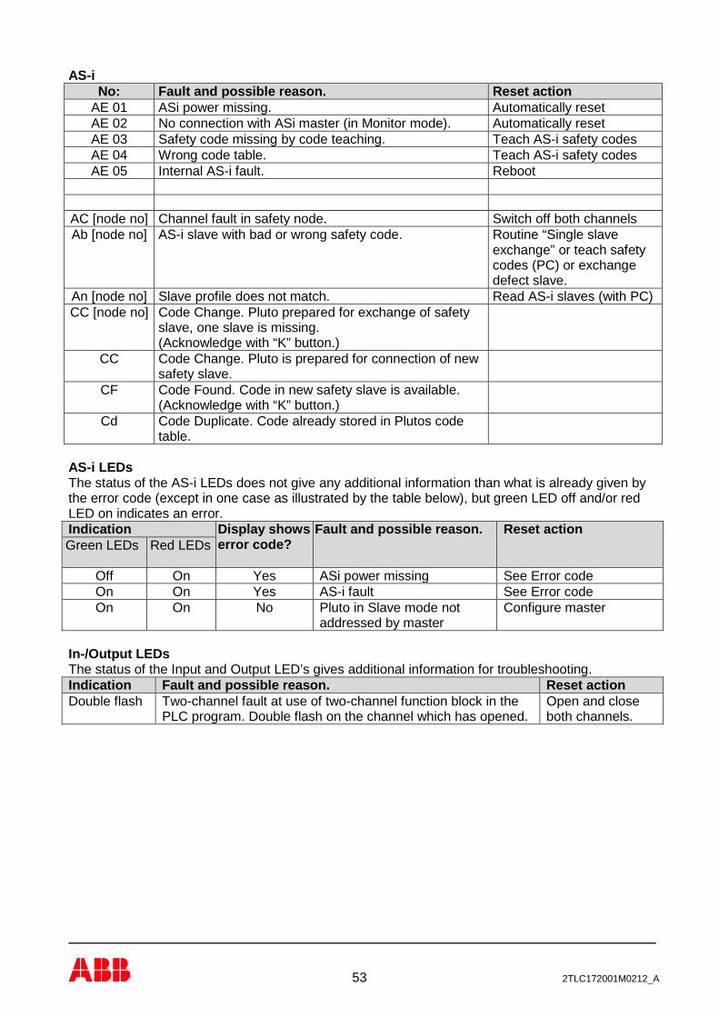
53 2TLC172001M0212_A
AS-i No: Fault and possible reason. Reset action
AE 01 ASi power missing. Automatically reset AE 02 No connection with ASi master (in Monitor mode). Automatically reset AE 03 Safety code missing by code teaching. Teach AS-i safety codes AE 04 Wrong code table. Teach AS-i safety codes AE 05 Internal AS-i fault. Reboot
AC [node no] Channel fault in safety node. Switch off both channels Ab [node no] AS-i slave with bad or wrong safety code. Routine “Single slave
exchange” or teach safety codes (PC) or exchange defect slave.
An [node no] Slave profile does not match. Read AS-i slaves (with PC) CC [node no] Code Change. Pluto prepared for exchange of safety
slave, one slave is missing. (Acknowledge with “K” button.)
CC Code Change. Pluto is prepared for connection of new safety slave.
CF Code Found. Code in new safety slave is available. (Acknowledge with “K” button.)
Cd Code Duplicate. Code already stored in Plutos code table.
AS-i LEDs The status of the AS-i LEDs does not give any additional information than what is already given by the error code (except in one case as illustrated by the table below), but green LED off and/or red LED on indicates an error. Indication Display shows
error code?
Fault and possible reason. Reset action Green LEDs Red LEDs
Off On Yes ASi power missing See Error code On On Yes AS-i fault See Error code On On No Pluto in Slave mode not
addressed by master Configure master
In-/Output LEDs The status of the Input and Output LED’s gives additional information for troubleshooting. Indication Fault and possible reason. Reset action Double flash Two-channel fault at use of two-channel function block in the
PLC program. Double flash on the channel which has opened. Open and close both channels.
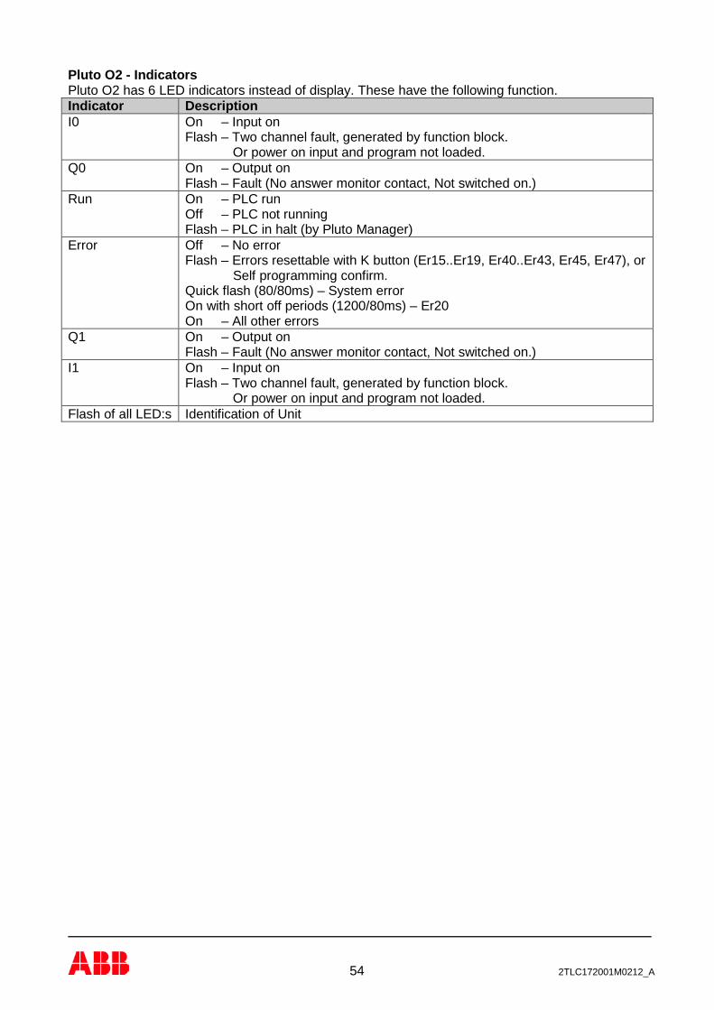
54 2TLC172001M0212_A
Pluto O2 - Indicators Pluto O2 has 6 LED indicators instead of display. These have the following function. Indicator Description I0 On – Input on
Flash – Two channel fault, generated by function block. Or power on input and program not loaded.
Q0 On – Output on Flash – Fault (No answer monitor contact, Not switched on.)
Run On – PLC run Off – PLC not running Flash – PLC in halt (by Pluto Manager)
Error Off – No error Flash – Errors resettable with K button (Er15..Er19, Er40..Er43, Er45, Er47), or Self programming confirm. Quick flash (80/80ms) – System error On with short off periods (1200/80ms) – Er20 On – All other errors
Q1 On – Output on Flash – Fault (No answer monitor contact, Not switched on.)
I1 On – Input on Flash – Two channel fault, generated by function block. Or power on input and program not loaded.
Flash of all LED:s Identification of Unit

55 2TLC172001M0212_A
EC declaration of conformity
We ABB AB Jokab Safety Viderögatan 2 SE-164 40 Kista Sweden
declare under our sole responsibility that the safety components of ABB manufacture, with type designations and safety functions as listed below, are in conformity with the Directives 2006/42/EC - Machinery 2014/30/EU - EMC 2014/35/EU - Low Voltage 2011/65/EU - RoHS
Programmable electronic safety system (Safety PLC system) Pluto version A20, B20, B16, S19, S20, D20, B22, B46, S46, D45, AS-i, B42 AS-i, O2 including accessories IDFIX, cables, documentation etc. where applicable.
Used harmonized standards
EN ISO 13849-1/EN 954-1 EN 62061 EN 61496-1 EN 574 EN 692 EN 60204-1 EN 50178 EN 61000-6-2 EN 61000-6-4 EN 61000-4-1…6
Other used standards and documents
IEC/EN 61508 DIN V VDE 0801:1990 with amendment A1:1994
EC Type-Examination according to 2006/42/EC
TÜV-Rheinland Am Grauen Stein D-51105 Köln Germany
Notified body No. 0035
Certificate no
01/205/5304/13
Tobias Gentzell Global R&D Manager GPG Motor Starting & Safety ABB AB Electrification Products Västerås/Sweden 2017-01-09

56 2TLC172001M0212_A
Contact information
Australia ABB Australia Pty Limited Low Voltage Products Tel: +61 (0)1300 660 299 Fax: +61 (0)1300 853 138 Mob: +61 (0)401 714 392 E-mail: [email protected] Web: www.abbaustralia.com.au Austria ABB AB, Jokab Safety Tel: +43 (0)1 601 09-6204 Fax: +43 (0)1 601 09-8600 E-mail: [email protected] Web: www.abb.at Belgium ABB N.V. Tel: +32 27186884 Fax: +32 27186831 E-mail: [email protected] Brazil ABB Ltda Produtos de Baixa Tensão ABB Atende: 0800 014 9111 Fax: +55 11 3688-9977 Web: www.abb.com.br Canada ABB Inc. Tel: +1 514 420 3100 Ext 3269 Fax: +1 514 420 3137 Mobile: +1 514 247 4025 E-mail: [email protected] Web: www.abb.com China ABB (China) Limited Tel: 86-21-23287948 Telefax: 86-21-23288558 Mobile: 86-186 2182 1159 E-mail: [email protected] Czech Republic ABB AB, Jokab Safety Tel: +420 543 145 482 Fax: +420 543 243 489 E-mail: [email protected] Web: www.abb.cz Denmark JOKAB SAFETY DK A/S Tel: +45 44 34 14 54 Fax: +45 44 99 14 54 E-mail: [email protected] Web: www.jokabsafety.dk ABB A/S Tel: +45 4450 4450 Fax: +45 4359 5920 E-mail: [email protected] Web: www.abb.dk Finland ABB Oy Web: www.abb.fi
France ABB France Division Produits Basse Tension Tel: 0825 38 63 55 Fax: 0825 87 09 26 Web: www.abb.com Germany ABB STOTZ-KONTAKT GmbH Tel: +49 (0) 7424-95865-0 Fax: +49 (0) 7424-95865-99 E-mail: [email protected] Web: www.abb.de Greece ΑΒΒ SA Tel: +30 210.28.91.900 Fax: +30 210.28.91.999 E-mail: [email protected] [email protected] Web: www.abb.com Ireland ABB Ltd. Tel +353 1 4057 381 Fax: +353 1 4057 312 Mobile: +353 86 2532891 E-mail: [email protected] Israel ABB Technologies Ltd. Tel: +972 4 851-9204 Mobile: +972 52 485-6284 E-mail: [email protected] Web: www.abb.co.il Italy ABB S.p.A. Tel. +39 02 2414.1 Fax +39 02 2414.2330 Web: www.abb.it Korea ABB KOREA Low-voltage Product Tel: +82 2 528 3177 Fax: +82 2 528 2350 Web: www.jokabsafety.co.kr Malaysia ABB Malaysia Tel: +60356284888 4282 E-mail: [email protected] Netherlands ABB b.v. Tel:+31 (0) 10 - 4078 947 Fax: +31 (0) 10 – 4078 090 E-mail: [email protected] Web: www.abb.nl Norway ABB AS Tel: +47 03500 Fax: +47 32858021 Mobile: +47 40918930 E-mail: [email protected] Web: www.abb.no
Poland ABB Sp. z.o.o Tel: +48 728 401 403 Fax: 22 220 22 23 E-mail: [email protected], [email protected] Web: www.abb.pl Portugal Asea Brown Boveri S.A. Low Voltage Products - Baixa Tensão Tel: +35 214 256 000 Fax: +35 214 256 390 Web: www.abb.es Slovenia ABB d.o.o. Tel: +386 1 2445 455 Fax: +386 1 2445 490 E-mail: [email protected] Spain Asea Brown Boveri S.A. Tel: +34 93 4842121 Fax: +34 93 484 21 90 Web: www.abb.es South Africa ABB Tel: +27 10 202 5906 Fax: +27 11 579 8203 Mobile: +27 82 500 7990 E-mail: [email protected] Sweden ABB AB, Jokab Safety Varlabergsvägen 11 SE-434 39 Kungsbacka Tel: +46 21 32 50 00 Fax: +46 40 67 15 601 E-mail: [email protected] Web: www.abb.com/jokabsafety Switzerland ABB Schweiz AG Industrie- und Gebäudeautomation Tel: +41 58 586 00 00 Fax: +41 58 586 06 01 E-mail: [email protected] Web: www.abb.ch Turkey ABB Elektrik Sanayi A.Ş Tel: 0216 528 22 00 Fax: 0216 365 29 44 United Kingdom ABB Ltd/JOKAB SAFETY UK Tel: +44 (0) 2476 368500 Fax: +44 (0) 2476 368401 E-mail: [email protected] Web: www.jokabsafety.com USA/Mexico ABB Jokab Safety North America Tel: +1 519 735 1055 Fax: +1 519 7351299 E-mail: [email protected] Web: www.jokabsafetyna.com