PLUS Viscount I Hydraulic Motor - Graco Inc.€¦ · 308330J EN Instructions - Parts List PLUS...
24
308330J EN Instructions - Parts List PLUS Viscount ® I Hydraulic Motor Used as hydraulic drive for reciprocating pumps. For professional use only. Parts 236417, Series A, and 261466, Series A Hydraulic Motor Parts 236418, Series C, and 253608, Series A, Hydraulic Reciprocator 1500 psi (10 MPa, 102 bar) Maximum Hydraulic Input Pressure See page 22 for maximum working pressures. See also Manual 311211, High-Flo ® Pumps Important Safety Instructions Read all warnings and instructions in this manual. Save these instructions. 236417 Motor Shown 3054
Transcript of PLUS Viscount I Hydraulic Motor - Graco Inc.€¦ · 308330J EN Instructions - Parts List PLUS...

308330JEN
Instructions - Parts List
PLUS
Viscount® I Hydraulic Motor
Used as hydraulic drive for reciprocating pumps. For professional use only.
Parts 236417, Series A, and 261466, Series A Hydraulic Motor
Parts 236418, Series C, and 253608, Series A, Hydraulic Reciprocator
1500 psi (10 MPa, 102 bar) Maximum Hydraulic Input Pressure
See page 22 for maximum working pressures.
See also Manual 311211, High-Flo® Pumps
Important Safety InstructionsRead all warnings and instructions in this manual. Save these instructions.
236417 Motor Shown
3054

Table of Contents
2 308330J
Table of ContentsTable of Contents . . . . . . . . . . . . . . . . . . . . . . . . . . 2Warnings . . . . . . . . . . . . . . . . . . . . . . . . . . . . . . . . . 3Installation . . . . . . . . . . . . . . . . . . . . . . . . . . . . . . . . 5
Grounding . . . . . . . . . . . . . . . . . . . . . . . . . . . . . . 5General . . . . . . . . . . . . . . . . . . . . . . . . . . . . . . . 5Install the Drain Bottle . . . . . . . . . . . . . . . . . . . . 6
Operation . . . . . . . . . . . . . . . . . . . . . . . . . . . . . . . . . 7Pressure Relief Procedure . . . . . . . . . . . . . . . . . 7Startup . . . . . . . . . . . . . . . . . . . . . . . . . . . . . . . . 7Shutdown & Care . . . . . . . . . . . . . . . . . . . . . . . . 7
Troubleshooting . . . . . . . . . . . . . . . . . . . . . . . . . . . 8Service . . . . . . . . . . . . . . . . . . . . . . . . . . . . . . . . . . . 8
Tools Required . . . . . . . . . . . . . . . . . . . . . . . . . . 8Disconnecting the Hydraulic Motor . . . . . . . . . . . 8Reconnecting the Hydraulic Motor . . . . . . . . . . . 9Motor Disassembly . . . . . . . . . . . . . . . . . . . . . . . 9Motor Reassembly . . . . . . . . . . . . . . . . . . . . . . 10
Reciprocator Service . . . . . . . . . . . . . . . . . . . . . . . 13Disassembly . . . . . . . . . . . . . . . . . . . . . . . . . . . 13Reassembly Part 236418 . . . . . . . . . . . . . . . . . 15Reassembly Part 253608 . . . . . . . . . . . . . . . . . 16
Parts . . . . . . . . . . . . . . . . . . . . . . . . . . . . . . . . . . . . 18
236418 Viscount® I Reciprocator, Series C . . . 18
253608 Viscount® I Reciprocator, Series A . . . 18Mounting Hole Layout . . . . . . . . . . . . . . . . . . . . 19
236417 Viscount® I Hydraulic Motor, Series A . 20261466 Viscount® I Hydraulic Motor, Series A . 21
Technical Data . . . . . . . . . . . . . . . . . . . . . . . . . . . . 22Sound Data . . . . . . . . . . . . . . . . . . . . . . . . . . . . 22Dimensions . . . . . . . . . . . . . . . . . . . . . . . . . . . . 23
Graco Standard Warranty . . . . . . . . . . . . . . . . . . . 24

Warnings
308330J 3
WarningsThe following warnings are for the setup, use, grounding, maintenance, and repair of this equipment. The exclama-tion point symbol alerts you to a general warning and the hazard symbols refer to procedure-specific risks. When these symbols appear in the body of this manual or on warning labels, refer back to these Warnings. Product-specific hazard symbols and warnings not covered in this section may appear throughout the body of this manual where applicable.
WARNINGWARNINGWARNINGWARNINGEQUIPMENT MISUSE HAZARDMisuse can cause death or serious injury.• Do not operate the unit when fatigued or under the influence of drugs or alcohol.• Do not exceed the maximum working pressure or temperature rating of the lowest rated system com-
ponent. See Technical Data in all equipment manuals.• Use fluids and solvents that are compatible with equipment wetted parts. See Technical Data in all
equipment manuals. Read fluid and solvent manufacturer’s warnings. For complete information about your material, request MSDS from distributor or retailer.
• Do not leave the work area while equipment is energized or under pressure. • Turn off all equipment and follow the Pressure Relief Procedure when equipment is not in use.• Check equipment daily. Repair or replace worn or damaged parts immediately with genuine manu-
facturer’s replacement parts only.• Do not alter or modify equipment. Alterations or modifications may void agency approvals and create
safety hazards.• Make sure all equipment is rated and approved for the environment in which you are using it.• Use equipment only for its intended purpose. Call your distributor for information.• Route hoses and cables away from traffic areas, sharp edges, moving parts, and hot surfaces.• Do not kink or over bend hoses or use hoses to pull equipment.• Keep children and animals away from work area.• Comply with all applicable safety regulations.
SKIN INJECTION HAZARDHigh-pressure fluid from gun, hose leaks, or ruptured components will pierce skin. This may look like just a cut, but it is a serious injury that can result in amputation. Get immediate surgical treatment.• Do not spray without tip guard and trigger guard installed.• Engage trigger lock when not spraying.• Do not point gun at anyone or at any part of the body.• Do not put your hand over the spray tip.• Do not stop or deflect leaks with your hand, body, glove, or rag.• Follow the Pressure Relief Procedure when you stop spraying and before cleaning, checking, or
servicing equipment. • Tighten all fluid connections before operating the equipment.• Check hoses and couplings daily. Replace worn or damaged parts immediately.
MOVING PARTS HAZARDMoving parts can pinch, cut or amputate fingers and other body parts.• Keep clear of moving parts.• Do not operate equipment with protective guards or covers removed.• Pressurized equipment can start without warning. Before checking, moving, or servicing equipment,
follow the Pressure Relief Procedure and disconnect all power sources.

Warnings
4 308330J
FIRE AND EXPLOSION HAZARDFlammable fumes, such as solvent and paint fumes, in work area can ignite or explode. To help prevent fire and explosion:• Use equipment only in well ventilated area.• Eliminate all ignition sources; such as pilot lights, cigarettes, portable electric lamps, and plastic drop
cloths (potential static arc). • Keep work area free of debris, including solvent, rags and gasoline.• Do not plug or unplug power cords, or turn power or light switches on or off when flammable fumes
are present.• Ground all equipment in the work area. See Grounding instructions.• Use only grounded hoses.• Hold gun firmly to side of grounded pail when triggering into pail. Do not use pail liners unless they
are antistatic or conductive.• Stop operation immediately if static sparking occurs or you feel a shock. Do not use equipment
until you identify and correct the problem.• Keep a working fire extinguisher in the work area.
TOXIC FLUID OR FUMES HAZARDToxic fluids or fumes can cause serious injury or death if splashed in the eyes or on skin, inhaled, or swallowed.• Read MSDSs to know the specific hazards of the fluids you are using.• Store hazardous fluid in approved containers, and dispose of it according to applicable guidelines.
PERSONAL PROTECTIVE EQUIPMENTWear appropriate protective equipment when in the work area to help prevent serious injury, including eye injury, hearing loss, inhalation of toxic fumes, and burns. This protective equipment includes but is not limited to:• Protective eyewear, and hearing protection. • Respirators, protective clothing, and gloves as recommended by the fluid and solvent manufacturer
WARNINGWARNINGWARNINGWARNING

Installation
308330J 5
Installation
Grounding
1. Pump: loosen the grounding lug locknut (W) and washer (X). Insert one end of a 12 ga. (1.5 mm2) minimum ground wire (Y) into the slot in lug (Z) and tighten the locknut securely. Connect the other end of the wire to a true earth ground. See FIG. 1. Order Graco Part. No. 237569.
2. Hydraulic hoses and fluid outlet hoses: use only electrically conductive hoses.
3. Hydraulic power supply: follow manufacturer’s rec-ommendations.
4. Spray gun/dispensing valve: obtain grounding through connection to a properly grounded fluid hose and pump.
5. Fluid supply container: according to local code.
6. Object being sprayed: according to local code.
7. Any pails used when flushing: use only metal, grounded pails when flushing. Make firm metal-to-metal contact between a metal part of the gun/ valve and the pail. Use the lowest possible pressure.
8. To maintain grounding continuity when flushing or relieving pressure, always hold a metal part of the gun/valve firmly to the side of a metal pail, and then open the gun/valve.
General Connect the hydraulic motor (A) to the displacement pump (B) as explained in your separate pump manual. See FIG. 2.
Mount the pump to suit the type of installation planned. Motor mounting plate kit 236714 (P) is available; contact your Graco distributor for more information.
Be sure that your power supply is equipped with a suc-tion filter to the hydraulic pump and a system return line filter of 10 micron size.
The equipment must be grounded to reduce the risk of static sparking. Static sparking can cause fumes to ignite or explode. Grounding provides an escape wire for the electric current.
FIG. 1
W
XZ
Y
NOTICE
Keep the hydraulic system clean
To reduce the risk of damaging the hydraulic power supply and motor, blow out all hydraulic lines with air, flush thoroughly with solvent, and then blow out with air again before connecting the lines to the hydraulic motor.
Always plug the hydraulic inlets, outlets, and lines when disconnecting them for any reason to avoid introducing dirt and other contaminants into the system.
Carefully follow the manufacturer’s recommendations on reservoir and filter cleaning, and periodic changes of the hydraulic fluid. The maximum water content of the hydraulic oil is 1 percent.

Installation
6 308330J
Install the Drain Bottle 1. Push the drain hose (113) securely onto the barbed
adapter (112). See FIG. 2.
2. Position the holder (115) on a pump tie rod (C) and secure with the hose clamp (116). Place the drain bottle (114) in the holder.
3. Place the drain hose (113) in the drain bottle so it hangs well down inside the bottle. Adjust the posi-tion of the holder, if necessary.
FIG. 2
3139
C
A
B
112
116
P
113
115
114

Operation
308330J 7
Operation
Pressure Relief Procedure
Fluid under high pressure can be injected through the skin and cause serious injury. To reduce the risk of an injury from injection, splashing fluid, or moving parts, fol-low the Pressure Relief Procedure whenever you:
• are instructed to relieve the pressure, • stop spraying, • check or service any of the system equipment, • or install or clean the spray tips.
1. Lock the spray gun/dispensing valve safety latch.
2. Close the supply line shutoff valve(s) first, then the return line shutoff valve(s). In a multi-pump system, do this at each pump to isolate the pumps.
3. Unlock the gun/valve safety latch.
4. Hold a metal part of the gun firmly to the side of a grounded metal pail, and trigger the gun/valve to relieve pressure.
5. Lock the gun/valve safety latch.
6. Open the pump outlet drain valve(s), having a con-tainer ready to catch the drainage.
7. Leave the drain valve(s) open until you are ready to spray/dispense again.
If you suspect that the tip/nozzle or hose is completely clogged, or that pressure has not been fully relieved after following the steps above, very slowly loosen the tip guard retaining nut or hose end coupling to relieve pressure gradually, then loosen completely and clear the obstruction.
Startup Before each use, check the hydraulic fluid level and add fluid as necessary to fill the lines.
To start the pump, turn on the hydraulic power supply. Open the return line shutoff valve first, then open the supply line shutoff valve.
Shutdown & Care
To reduce the risk of serious injury whenever you are instructed to relieve pressure, always follow the Pres-sure Relief Procedure, page 7.
Relieve the pressure. Always shut off the supply line shutoff valve first, and then the return line shutoff valve. This is to prevent over pressurizing the motor or its seals. When starting the hydraulic system, open the return line shutoff valve first.
Hydraulic Oil Temperature If hydraulic oil becomes too hot, it can reach its flash point and cause a fire. Operating at too high an oil temperature can also cause faster motor seal wear and leakage. The recommended hydraulic oil operating temperature is 80-115°F (27-45°C). If the oil temperature approaches 130°F (54°C), shut off the motor and check the hydraulic oil supply cooling system, filters, etc. Clean or repair as needed.
Always use Graco-approved Hydraulic Oil or equivalent. Order Part No. 169236, 5 gal. (19 liter) or 207428, 1 gal. (3.8 liter). Do not substitute a lower grade oil or one with a lower flash point.
The equivalent is a premium, ISO grade 46 petroleum-based hydraulic oil containing rust and oxidation inhibitors and anti-wear agents. Before using any other type of oil in this equipment, contact your Graco distributor. Unauthorized use of lesser grade oil or substitutes will void the warranty.

Troubleshooting
8 308330J
Troubleshooting
1. Follow Pressure Relief Procedure, page 7, before checking or servicing any system equipment.
2. Check all possible problems and causes before dis-assembling the motor.
Service
Tools Required • Set of allen wrenches
• Set of socket or box wrenches
• Adjustable wrench
• Torque wrench
• Spanner wrench
• O-ring pick
• 10-24 unc-2b tap
• Vise
• Shallow metal or plastic pan (approx. 12 x 20 in.)
• Repair Tool 189305
• Thread lubricant
• Lithium-base grease
• Fresh Loctite® 242 and 609 thread sealants and
Loctite® Primer T or Perma-Loc® 115 thread seal-
ant and Perma-Bond® Surface Conditioner I
• Chlorinated solvent
Disconnecting the Hydraulic Motor
To reduce the risk of serious injury whenever you are instructed to relieve pressure, always follow the Pres-sure Relief Procedure on page 7.
1. Relieve the pressure.
2. Disconnect the hydraulic hoses and plug all hydrau-lic connections and hoses.
Problem Cause Solution
Reciprocator stops running. Worn valve or valve balls (3); broken valve spring (18).
Repair valve. See page 13.
Broken trip rod (17), spring (12) or retainers (11).
Replace parts. See page 13.
Poor performance or reduced effi-ciency.
Worn piston seals (5, 6, 7). Replace seals. See page 13.
Oil leaking down extension rod. Worn o-ring (117, 121, or 122) in oil deflector.
Replace o-ring. See page 9.
Oil leaking around cylinder. Worn cylinder o-rings (2). Replace o-rings. See page 13.
Loose tie rods (37). Tighten nuts (106). See page 9.
Oil leaking around inlet or return tube fittings.
Loose fittings or worn fitting o-rings. Tighten or replace fittings (31, 34, 38). See page 13.
Excessive oil in drain bottle, or bottle needs frequent emptying.
Worn seals in bottom cylinder cap. Replace seals (2, 15, 14 and 49). See page 13.
NOTICE
Keep the hydraulic system clean Always plug the hydraulic inlets, outlets, and lines when disconnecting them for any reason to avoid introducing dirt and other contaminants into the system.

Service
308330J 9
3. Disconnect the hydraulic motor from the displace-ment pump as explained in your separate pump manual.
4. Pull the drain hose (113) off the barbed adapter (112).
Reconnecting the Hydraulic Motor 1. Reconnect the drain hose (113) to the barbed
adapter (112).
2. Reconnect the hydraulic motor to the displacement pump as explained in your separate pump manual.
3. Unplug all hydraulic connections and hoses. Recon-nect the hydraulic hoses.
Motor Disassembly
To reduce the risk of serious injury whenever you are instructed to relieve pressure, always follow the Pres-sure Relief Procedure on page 7.
1. Relieve the pressure.
2. Stand the motor upright. Remove the four screws (104) and washers (105) holding the motor cap (102) to the base (103). Lift the reciprocator (101) off the base (103) and lay it in a pan. Remove the large o-ring (108) from the base (103). See FIG. 3.
3. For model 236417 only, remove the cotter pin (111) and unscrew the extension rod (110) from the recip-rocator displacement rod (9). See FIG. 4.
4. Remove deflector.
• Model 236417, pull the oil deflector (109) off the extension rod (110). Remove the o-ring (117) from the deflector.
• Model 261466, remove the retaining o-ring and slide the deflector off the rod.
5. Unscrew the nuts (106) and washers (105) from the reciprocator tie rods (37) and pull the motor cap (102) off the reciprocator (101). Remove the o-ring (107) from the cap.
6. Clean and inspect all parts. Replace parts as neces-sary. See Reciprocator Service, page 13.
FIG. 3
3056
112
120
103
108
102
105
104
101
34
Model 236417
Grease.1
1

Service
10 308330J
Motor Reassembly1. Grease the o-ring (107) and install it on the motor
cap (102). Install the motor cap, washers (105) and nuts (106) on the reciprocator tie rods (37). Torque the nuts to 29-31 ft-lb (39-42 N•m). See FIG. 4.
2. Connect deflector.
• Model 236417 (see FIG. 4 and FIG. 5), grease the o-ring (117). Install it in the inner groove of the oil deflector (109). Slide the deflector onto the extension rod (110), beveled side facing up, until it seats.
• Model 261466 (see FIG. 4 and FIG. 6), grease the thinner o-ring (121) and install on the dis-placement rod (9). Slide the deflector onto the displacement rod, beveled side facing up, until it seats. Install the thicker o-ring (122).
3. For model 236417 only, apply thread lubricant to the threads of the extension rod (110) and screw it into the reciprocator displacement rod (9) until the pin holes align. Install the cotter pin (111).
4. Grease the large o-ring (108) and install it on top of the motor base (103). Set the reciprocator (101) and motor cap (102) on the motor base. Orient the recip-rocator fluid inlet (34) to the grounding lug (120) as shown in FIG. 3.
5. Secure the motor cap (102) to the base (103) with four washers (105) and screws (104). Torque the screws to 29-31 (39-42 N•m).
FIG. 4
106
105
37
101
111
9
107
102
117
109
1
1
4
2
110
3057
ti9005a
Model 236417
Model 261466
10137
105106
9
107
102
121122
109
3
1
11
4
3
Grease.
Apply thread lubricant
Torque to 29-31 ft-lb (39-42 N•m)
Beveled side faces up.
1
2
3
4

Service
308330J 11
FIG. 5
Grease.
Apply thread lubricant.
Beveled side faces up.
Torque to 29-31 ft-lb (39-42 N•m)
1
2
4
5
107
101
104105
102
111
109
108
103
110
117
9
2
1
1
4
5
1
Model 236417
3058

Service
12 308330J
FIG. 6
Grease.
Beveled side faces up.
Torque to 29-31 ft-lb (39-42 N•m)
1
4
5
107
101
104
105
102
109
108
103
122
121
9
1
1
4
5
1
Model 261466
ti9006a
1

Reciprocator Service
308330J 13
Reciprocator Service
Disassembly NOTE: Repair Kit 236698 is available. For the best results, use all the parts in the kit. Kit parts are marked with an asterisk, for example (2*).
NOTE: When disassembling, lay out all parts in sequence, to make reassembly easier. Clean and inspect all parts for wear or damage before reassem-bling. Replace as necessary.
1. Remove the reciprocator from the motor base. See Motor Disassembly, page 9. Lay it on its side in a pan.
2. Un-thread the tie rods (37) from the retainer (36) and pull them out through the top of the reciproca-tor. It should not be necessary to remove the four nuts (27) and lock washers (28).
3. Unscrew the four fluid tube nuts (N) and remove the tubes (32, 39). See FIG. 7. Allow excess oil to drain from the reciprocator, then plug the fluid fittings.
4. Pull the top cylinder cap (1), cylinder (33), and dis-placement rod (9) together off the bottom cylinder cap (35). Remove the o-ring (2) from the bottom cap.
5. Grasp the top cap (1) and pull the cylinder (33) off. Slide the cylinder off the displacement rod (9). Be careful not to damage the rod. Remove the o-ring (2) from the top cap.
6. Lay the top cap (1) and displacement rod (9) on a table. Place a clean rag around the yoke (4) to pre-vent the detent balls (3) from popping out. Push the yoke (4) sideways off the valve sleeve (19) while holding the balls (3) and spring (18) with the rag, then carefully remove the balls and spring.
7. Inspect the valve sleeve (19), valve stop (25), and spool (S) for damage. If any of these parts requires replacement, unscrew the two screws (26) holding
the stop (25) to the spool (S). Remove the stop and slide the sleeve (19) off the spool. If the spool is damaged, replace the top cap (1).
NOTE: If any of these parts are being reused, thor-oughly clean any adhesive residue from the screws and female threads of the spool. Use a surface cleaner such as chlorinated solvent on the threads and blow dry with compressed air. If necessary, use a 10-24 unc-2b tap to remove adhesive from the female threads.
8. Remove the cap screw (23), sealing washer (22) and o-ring (24) from the cap plate (29). Lift off the cap plate and remove the o-ring (20).
9. Hold the flats of the displacement rod (9) in a vise and use a spanner wrench in the pin holes of the piston (16) to screw it off the rod. Remove the trip rod (17) from the displacement rod.
10. Unscrew the nut (48) and remove the retainers (11) and spring (12) from the trip rod (17).
11. Slide the piston (16) off the trip rod (17). Remove the bearing (5), seal (6), and o-rings (7 and 8) from the piston.
12. Inspect the yoke (4) and trip rod (17) for damage. If either part requires replacement, slide the yoke into Repair Tool 189305 and set the tool in a vise. See FIG. 8. Use a wrench on the flats of the trip rod and unscrew the rod from the yoke.
13. Pull the housing retainer (36) away from the bottom cylinder cap (35).
14. Remove the block packings (14 and 49), wiper (15), bearing (13), and o-ring (2) from the housing retainer and bottom cylinder cap.
NOTICE
Keep the hydraulic system clean
Always plug the hydraulic inlets, outlets, and lines when disconnecting them for any reason to avoid introducing dirt and other contaminants into the system.
NOTICE
Be careful not to scratch the outside of the displace-ment rod.

Reciprocator Service
14 308330J
FIG. 7
5*
39 (Ref)
6*
7*
16
8*
11
12*
11
48*
9
N
38
35
49*
13*
14*15*
2*
36
34
N
32 (Ref)
2*
33
2*
17
*3*1826
25
*3
194
32
S
N
31
22
*24
23
27
28
29
20*1
38
N
39
50
37
3063a
9(253608 Only)
(236418 Only)

Reciprocator Service
308330J 15
Reassembly Part 2364181. Install the block packing (14*) and wiper (15*) in the
housing retainer (36). The spring of the block pack-ing and the lips of the wiper must face up. Install the o-ring (2*) on the top surface of the retainer. See FIG. 8.
2. Install the bearing (13*) and block packing (49*) in the bottom cylinder cap (35). The lips of the block packing must face up.
3. Reassemble the housing retainer (36) and the bot-tom cylinder cap (35).
NOTE: Thread sealant and primer are required. See Tools Required on page 8 for specifications. Loctite® 609 is used only in step 4 below. Use Loctite® 242 thread sealant and Loctite® Primer T or Perma-Loc® 115 in all other steps as required.
4. To reassemble the yoke (4) and trip rod (17), clean the threads with primer or chlorinated solvent and let dry for 3 to 4 minutes. Apply Loctite® 609 thread sealant to the female threads of the yoke. Slide the yoke into Repair Tool 189305 and place the tool in a vise. Using a wrench on the flats of the trip rod, screw the rod into the yoke. Torque to 96-100 in-lb (10.8-11.2 N•m).
5. Install the bearing (5*), o-ring (7*), and seal (6*) on the piston (16). Install the second o-ring (8*) on the underside of the piston. Slide the piston onto the trip rod (17) so the wide end of the piston faces the yoke (4).
6. Install the retainers (11) and spring (12*) on the trip rod (17). Screw the nut (48*) onto the rod until it runs out of thread, so that it bottoms out on the shoulder of the rod. See the Detail in FIG. 8.
7. Hold the flats of the displacement rod (9) in a vise. Slide the trip rod (17) into the displacement rod. Use a spanner wrench in the pin holes of the piston (16) to screw it into the displacement rod. Torque to 30-40 ft-lb (41-54 N•m).
8. Install the o-ring (20*) in the top cylinder cap (1), then install the cap plate (29), o-ring (24*), sealing washer (22), and cap screw (23).
9. To reassemble the valve sleeve (19) and valve stop (25), slide the sleeve (19) onto the valve spool (S). (Either side of the sleeve can face up.) Apply primer to the threads of the screws (26) and let dry for 3 to 4 minutes. Apply 1 or 2 drops of thread sealant to
the female threads of the spool (S). Install the stop (25) and torque the screws (26) to 42-45 in-lb (4.7-5.1 N•m).
10. To assemble the valve mechanism, use Repair Tool 189305 as follows:
a. Slide the yoke (4) into the repair tool, as shown in the Detail in FIG. 8. Align the upper detent holes (H) of the yoke with the center line of the tool.
b. Insert the spring (18*) and one ball (3*) into the valve stop (25). Tilt the valve stop and start guiding it into the tool, making sure the ball is sliding into the rounded slot in the tool.
c. Place the second ball (3*) at the other end of the spring (18*) and push it in with your thumb while rotating the valve stop (25) until the spring is horizontal and the balls are in place. Continue holding this assembly together.
d. Align the curved ends of the yoke with the valve sleeve groove, then press the assemblies firmly together. Make sure the balls snap into the upper detent holes (H) of the yoke (4), and the curved ends of the yoke engage the valve sleeve (19) groove. To remove the tool, slide it over the trip rod (17).
11. Place the bottom cylinder cap (35) in a vise. Install the o-ring (2*) in the cap. Set the cylinder (33) on the bottom cap.
12. Install the o-ring (2*) in the top cylinder cap (1). Make sure the hydraulic fittings (31, 34, and 38) are oriented as shown in FIG. 7, then slide the displace-ment rod (9) and piston (16) into the cylinder (33) until it seats in the top cap.
13. Install the tie rods (37). If the nuts and washers were removed, screw them onto the ends with short threads. Torque the nuts (27) to 28-30 ft-lb (38-41 N•m).
14. Remove the plugs from the fluid fittings (31, 34 and 38). Install the tubes (32, 39) and tighten the four fluid tube nuts (N).
15. Reinstall the reciprocator on the motor base. See Motor Reassembly, page 10.
NOTICE
When inserting the piston into the cylinder, carefully guide the piston seal (6*) and bearing (5*) to prevent damage to these parts.

Reciprocator Service
16 308330J
Reassembly Part 2536081. Install the o-ring (20*) in the top cylinder cap (1),
then install the cap plate (29), o-ring (24*), sealing washer (22), and cap screw (23).
NOTE: Thread sealant and primer are required. See Tools Required on page 8 for specifications. Loctite® 609 is used only in step 6 below. Use Loctite® 242 thread sealant and Loctite® Primer T or Perma-Loc® 115 in all other steps as required.
2. To reassemble the valve sleeve (19) and valve stop (25), slide the sleeve (19) onto the valve spool (S). (Either side of the sleeve can face up.) Apply primer to the threads of the screws (26) and let dry for 3 to 4 minutes. Apply 1 or 2 drops of thread sealant to the female threads of the spool (S). Install the stop (25) and torque the screws (26) to 42-45 in-lbs (4.7-5.1 N•m). Install the o-ring (2*) in the top cylin-der cap (1).
3. Install the block packing (14*) and wiper (15*) in the housing retainer (36). The spring of the block pack-ing and the lips of the wiper must face up. Install the o-ring (2*) on the top surface of the retainer. See FIG. 8.
4. Install the bearing (13*) and block packing (49*) in the bottom cylinder cap (35). The lips of the block packing must face up.
5. Reassemble the housing retainer (36) and the bot-tom cylinder cap (35).
6. To reassemble the yoke (4) and trip rod (17), clean the threads with primer or chlorinated solvent and let dry for 3 to 4 minutes. Apply Loctite® 609 thread sealant to the female threads of the yoke. Slide the yoke into Repair Tool 189305 and place the tool in a vise. Using a wrench on the flats of the trip rod, screw the rod into the yoke. Torque to 96-100 in-lbs (10.8-11.2 N•m).
7. Install the o-ring (7*), and seal (6*) on the piston (16). Install the second o-ring (8*) on the underside of the piston. Slide the piston onto the trip rod (17) so the wide end of the piston faces the yoke (4).
8. Install the retainers (11) and spring (12*) on the trip rod (17). Screw the nut (48*) onto the rod until it runs out of thread, so that it bottoms out on the shoulder of the rod. See the Detail in FIG. 8.
9. Slide the displacement rod (9) into the bottom of the cylinder cap (35), first passing through the housing retainer (36) so that the o-ring grooves on the dis-placement rode do not pass through the block pack-ing (14*).
10. Place the bottom cylinder cap (35) in a vise. Slide the trip rod (17) into the displacement rod. Use a spanner wrench in the pin holes of the piston (16) to screw it into the displacement rod. Torque to 30-40 ft-bs (41-54 N•m).
11. Install the o-ring (2*) in the bottom cylinder cap. Install the bearing (5*) on the piston (16). Slide the cylinder (33) over the displacement rod (9) and pis-ton (16) until it seals on the bottom cap.
12. To assemble the valve mechanism, use Repair Tool 189305 as follows:
a. Slide the yoke (4) into the repair tool, as shown in the Detail in FIG. 8. Align the upper detent holes (H) of the yoke with the center line of the tool.
b. Insert the spring (18*) and one ball (3*) into the valve stop (25). Tilt the valve stop and start guiding it into the tool, making sure the ball is sliding into the rounded slot in the tool.
c. Place the second ball (3*) at the other end of the spring (18*) and push it in with your thumb while rotating the valve stop (25) until the spring is horizontal and the balls are in place. Continue holding this assembly together.
d. Align the curved ends of the yoke with the valve sleeve groove, then press the assemblies firmly together. Make sure the balls snap into the upper detent holes (H) of the yoke (4), and the curved ends of the yoke engage the valve sleeve (19) groove. To remove the tool, slide it over the trip rod (17).
13. Make sure the hydraulic fittings (31, 34, and 38) are oriented as shown in FIG. 7 install the top cylinder cap (1) until it seats on the cylinder (33).
14. Install the tie rods (37). If the nuts and washers were removed, screw them onto the ends with short threads. Torque the nuts (27) to 28-30 ft-lbs (38-41 N•m).
15. Remove the plugs from the fluid fittings (31, 34 and 38). Install the tubes (32, 39) and tighten the four fluid tube nuts (N).
16. Reinstall the reciprocator on the motor base. See Motor Reassembly, page 10.
NOTICE
When inserting the piston into the cylinder, carefully guide the piston seal (6*) and bearing (5*) to prevent damage to these parts.
Reciprocator Service
308330J 17
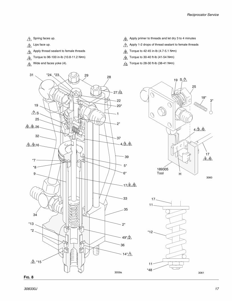
FIG. 8
Spring faces up. Apply primer to threads and let dry 3 to 4 minutes
Lips face up. Apply 1-2 drops of thread sealant to female threads
Apply thread sealant to female threads Torque to 42-45 in-lb (4.7-5.1 N•m)
Torque to 96-100 in-lb (10.8-11.2 N•m) Torque to 30-40 ft-lb (41-54 N•m)
Wide end faces yoke (4). Torque to 28-30 ft-lb (38-41 N•m)
1 6
2 7
3 8
4 9
5 10
29 28
27
22
10
20*
1
2*
37
4 3 6
39
5*
6*
17 4 6
33
35
2*
49*
36
14* 1
*152
*2
*13
34
9
*8
*7
165 9
32
266 8
25
S7
19
31 *24 *23
18*3*
25
19 S 7
4 3 6
174 6
H189305Tool
17
11
*12
11
*483059a 3061
3060
2

Parts
18 308330J
Parts
236418 Viscount® I Reciprocator, Series C253608 Viscount® I Reciprocator, Series A
5*
39 (Ref)
6*
7*
16
8*
11
12*
11
48*
9
38
35
49*
13*
14*15*
2*
36
34
32 (Ref)
*2
33
*2
17
*3*1826
25
*3
194
32
32
31
22
*24
23
27
28
29
20*1
38
39
50
37
3063a
10▲
9(253608 Only)
(236418 Only)

Parts
308330J 19
Mounting Hole Layout
Ref No. Part No. Description Qty
1 236594 TOP CAP ASSEMBLY 12* 106274 O-RING; buna-N 33* 100069 BALL; carbon steel 24 189077 YOKE, valve 15* 178207 BEARING, piston; bronze-filled PTFE 16* 178226 SEAL, piston; glass-filled PTFE 17* 108014 O-RING; buna-N 18* 105765 O-RING; buna-N 19 189070 ROD, displacement, 236418 only 1
15H840 ROD, displacement, 253608 only 110▲ 179885 LABEL, warning 111 189069 RETAINER, spring 212* 178189 SPRING, compression 113* 112342 BEARING, rod; bronze-filled PTFE 114* 112340 PACKING, block; nitrile rubber 115* 112341 WIPER, rod; nitrile rubber 116 192656 PISTON 117 192657 ROD, trip 118* 108437 SPRING, compression 119 189072 SLEEVE, valve 120* 104093 O-RING; buna-N 122 178179 WASHER, sealing 123 106276 SCREW, cap, hex hd; 3/8-4 unf-a
0.625 (16 mm) long1
24* 155685 O-RING; buna-N 125 192654 STOP, valve 1
26 104092 SCREW, cap, socket hd; 10-24 unrc-3a; 0.625 (16 mm) long
2
27 106292 NUT, hex; 3/8-24 unf-2b 428 100133 WASHER, lock; 3/8 in. size 429 178181 PLATE, cap 131 106470 ELBOW, 90°; 3/4-16 unf-2a; fits 1/2
in. (13 mm) diameter tube1
32 236419 TUBE, inlet; w/3/4-16 unf-2b fittings 133 178229 CYLINDER 134 107197 TEE; 3/4-16 unf-2a 135 189073 CAP, cylinder, bottom 136 189074 RETAINER, housing 137 189075 ROD, tie 438 110792 ELBOW, 90°; 7/16-20 unf-2a x
9/16-18 unf-2a; fits 3/8 in. (10 mm) diameter tube
2
39 236420 TUBE, drain; w/9/16-18 unf-2b fittings 148* 114231 NUT, hex, locking; w/nylon insert;
10-32 unf-3b1
49* 112561 PACKING, block; urethane 150 107195 ADAPTER, straight thread, 37° flare;
3/4-16 unf-2a x 7/8-14 unf-2a1
* These parts are included in Repair Kit 236698, which may be purchased separately.
▲ Replacement Danger and Warning labels, tags, and cards are available at no cost.
Ref No. Part No. Description Qty
3 Tie Rod Mounting
2.62” (67 mm) Dia. Cutout
Three 1/2- 3 unc (2b) holes on a 3.5” (89 mm) dia bolt circle.Three 0.45” (11.5 mm) countersunk holes with M10 x 1.5 threaded holes on a 4.92” (125 mm) bolt circle.Four 5/16-18 unc (2b) threaded holes on a 6.4” (163 mm) dia bolt circle for adapter plate mounting holes.
1
2
3
4
4
2
31
Parts
20 308330J
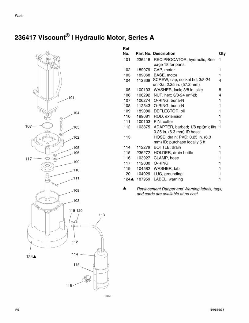
236417 Viscount® I Hydraulic Motor, Series A
101
104
112
105
102
105106
109
110
111
108
103
119 120113
114
115
116
124▲
117
107
3062
Ref No. Part No. Description Qty
101 236418 RECIPROCATOR, hydraulic, See page 18 for parts.
1
102 189079 CAP, motor 1103 189068 BASE, motor 1104 112339 SCREW, cap, socket hd; 3/8-24
unf-3a; 2.25 in. (57.2 mm)4
105 100133 WASHER, lock; 3/8 in. size 8106 106292 NUT, hex; 3/8-24 unf-2b 4107 106274 O-RING; buna-N 1108 112343 O-RING; buna-N 1109 189080 DEFLECTOR, oil 1110 189081 ROD, extension 1111 100103 PIN, cotter 1112 103875 ADAPTER, barbed; 1/8 npt(m); fits
0.25 in. (6.3 mm) ID hose1
113 HOSE, drain; PVC; 0.25 in. (6.3 mm) ID; purchase locally 6 ft
114 112279 BOTTLE, drain 1115 236272 HOLDER, drain bottle 1116 103927 CLAMP, hose 1117 112030 O-RING 1119 104582 WASHER, tab 1120 104029 LUG, grounding 1124▲ 187959 LABEL, warning 1
▲ Replacement Danger and Warning labels, tags, and cards are available at no cost.

Parts
308330J 21
261466 Viscount® I Hydraulic Motor, Series A
101
104
112
105
102
105106
109
108
103
119 120113
114
115
116
124▲
122
107
121
ti9004a
Ref No. Part No. Description Qty
101 253608 RECIPROCATOR, hydraulic, See page 18 for parts.
1
102 189079 CAP, motor 1103 189068 BASE, motor 1104 112339 SCREW, cap, socket hd; 3/8-24
unf-3a; 2.25 in. (57.2 mm)4
105 100133 WASHER, lock; 3/8 in. size 8106 106292 NUT, hex; 3/8-24 unf-2b 4107 106274 O-RING; buna-N 1108 112343 O-RING; buna-N 1109 15K222 DEFLECTOR, oil 1112 103875 ADAPTER, barbed; 1/8 npt(m); fits
0.25 in. (6.3 mm) ID hose1
113 HOSE, drain; PVC; 0.25 in. (6.3 mm) ID; purchase locally 6 ft
114 112279 BOTTLE, drain 1115 236272 HOLDER, drain bottle 1116 103927 CLAMP, hose 1119 104582 WASHER, tab 1120 104029 LUG, grounding 1121 118381 O-RING, packing 1122 15K234 O-RING, packing 1124▲ 187959 LABEL, warning 1
▲ Replacement Danger and Warning labels, tags, and cards are available at no cost.

Technical Data
22 308330J
Technical Data
Sound Data
US MetricMaximum hydraulic fluid input pressure 1500 psi 10.5 MPa, 105 barMaximum hydraulic fluid input volume 3 gpm 11.3 liter/minFluid consumption rate 6.5 ounces per cycle
(1 gallon per 19.5 cycles)0.195 liter per cycle
Maximum water content of hydraulic fluid 1 percentMaximum hydraulic fluid temperature 130°F 54°CEffective piston area 1.48 in2 9.55 cm2
Piston rod diameter 1-3/8 in. 34.9 mmStroke 4 in. 101.6 mmThrust at 1500 psi (10.5 MPa, 105 bar) 2200 lb (9875 N)Weight with base 28 lb (124.6 N)NotesLoctite® is a registered trademark of the Loctite Corporation. Perma-Loc® and Perma-Bond® are registered trademarks of Perma-Loc Company.
Hydraulic Pressure dBa at 20 cycles/minute dBa at 30 cycles/minute dBa at 60 cycles/minute
500 psi (35 bar) 76.1 77.9 79.5
1000 psi (70 bar) 78.0 78.6 80.5
1500 psi (105 bar) 78.7 80.9 83.0
Technical Data
308330J 23
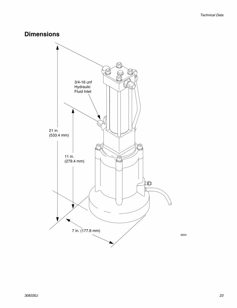
Dimensions
7 in. (177.8 mm)
11 in. (279.4 mm)
21 in. (533.4 mm)
3/4-16 unfHydraulicFluid Inlet
3054

All written and visual data contained in this document reflects the latest product information available at the time of publication. Graco reserves the right to make changes at any time without notice.
Original instructions. This manual contains English. MM 308330
Graco Headquarters: MinneapolisInternational Offices: Belgium, China, Japan, Korea
GRACO INC. AND SUBSIDIARIES • P.O. BOX 1441 • MINNEAPOLIS MN 55440-1441 • USA
Copyright 1994, Graco Inc. All Graco manufacturing locations are registered to ISO 9001.www.graco.com
Revision J, April, 2014
Graco Standard WarrantyGraco warrants all equipment referenced in this document which is manufactured by Graco and bearing its name to be free from defects in material and workmanship on the date of sale to the original purchaser for use. With the exception of any special, extended, or limited warranty published by Graco, Graco will, for a period of twelve months from the date of sale, repair or replace any part of the equipment determined by Graco to be defective. This warranty applies only when the equipment is installed, operated and maintained in accordance with Graco’s written recommendations.
This warranty does not cover, and Graco shall not be liable for general wear and tear, or any malfunction, damage or wear caused by faulty installation, misapplication, abrasion, corrosion, inadequate or improper maintenance, negligence, accident, tampering, or substitution of non-Graco component parts. Nor shall Graco be liable for malfunction, damage or wear caused by the incompatibility of Graco equipment with structures, accessories, equipment or materials not supplied by Graco, or the improper design, manufacture, installation, operation or maintenance of structures, accessories, equipment or materials not supplied by Graco.
This warranty is conditioned upon the prepaid return of the equipment claimed to be defective to an authorized Graco distributor for verification of the claimed defect. If the claimed defect is verified, Graco will repair or replace free of charge any defective parts. The equipment will be returned to the original purchaser transportation prepaid. If inspection of the equipment does not disclose any defect in material or workmanship, repairs will be made at a reasonable charge, which charges may include the costs of parts, labor, and transportation.
THIS WARRANTY IS EXCLUSIVE, AND IS IN LIEU OF ANY OTHER WARRANTIES, EXPRESS OR IMPLIED, INCLUDING BUT NOT LIMITED TO WARRANTY OF MERCHANTABILITY OR WARRANTY OF FITNESS FOR A PARTICULAR PURPOSE.
Graco’s sole obligation and buyer’s sole remedy for any breach of warranty shall be as set forth above. The buyer agrees that no other remedy (including, but not limited to, incidental or consequential damages for lost profits, lost sales, injury to person or property, or any other incidental or consequential loss) shall be available. Any action for breach of warranty must be brought within two (2) years of the date of sale.
GRACO MAKES NO WARRANTY, AND DISCLAIMS ALL IMPLIED WARRANTIES OF MERCHANTABILITY AND FITNESS FOR A PARTICULAR PURPOSE, IN CONNECTION WITH ACCESSORIES, EQUIPMENT, MATERIALS OR COMPONENTS SOLD BUT NOT MANUFACTURED BY GRACO. These items sold, but not manufactured by Graco (such as electric motors, switches, hose, etc.), are subject to the warranty, if any, of their manufacturer. Graco will provide purchaser with reasonable assistance in making any claim for breach of these warranties.
In no event will Graco be liable for indirect, incidental, special or consequential damages resulting from Graco supplying equipment hereunder, or the furnishing, performance, or use of any products or other goods sold hereto, whether due to a breach of contract, breach of warranty, the negligence of Graco, or otherwise.
FOR GRACO CANADA CUSTOMERSThe Parties acknowledge that they have required that the present document, as well as all documents, notices and legal proceedings entered into, given or instituted pursuant hereto or relating directly or indirectly hereto, be drawn up in English. Les parties reconnaissent avoir convenu que la rédaction du présente document sera en Anglais, ainsi que tous documents, avis et procédures judiciaires exécutés, donnés ou intentés, à la suite de ou en rapport, directement ou indirectement, avec les procédures concernées.
Graco InformationFor the latest information about Graco products, visit www.graco.com.
For patent information, see www.graco.com/patents.
TO PLACE AN ORDER, contact your Graco distributor or call to identify the nearest distributor.Phone: 612-623-6921 or Toll Free: 1-800-328-0211 Fax: 612-378-3505