Plta Lrines., A Flecd Manual Bots1wana - World...
60
TAG TECHNICAL NOTE NUMBER 8 - Plta Lrines., A Flecd Manual tor Bots1wana John van Nostrand and James G. Wilson i' I.1 ' J' A joint contribution of the Goverrnment of Botswana, the United Nations Development Programme and The World Bank to the International Water Supply and Sanitation Decade. Public Disclosure Authorized Public Disclosure Authorized Public Disclosure Authorized Public Disclosure Authorized Public Disclosure Authorized Public Disclosure Authorized Public Disclosure Authorized Public Disclosure Authorized
Transcript of Plta Lrines., A Flecd Manual Bots1wana - World...

TAG TECHNICAL NOTE NUMBER 8 -
Plta Lrines.,A Flecd Manual
tor Bots1wanaJohn van Nostrand and James G. Wilson
i' I.1 ' J'
A joint contribution of the Goverrnment of Botswana, theUnited Nations Development Programme and The WorldBank to the International Water Supply and SanitationDecade.
Pub
lic D
iscl
osur
e A
utho
rized
Pub
lic D
iscl
osur
e A
utho
rized
Pub
lic D
iscl
osur
e A
utho
rized
Pub
lic D
iscl
osur
e A
utho
rized
Pub
lic D
iscl
osur
e A
utho
rized
Pub
lic D
iscl
osur
e A
utho
rized
Pub
lic D
iscl
osur
e A
utho
rized
Pub
lic D
iscl
osur
e A
utho
rized
TAG TECHNICAL NOTE NUMBER 8
Rural IVentilated ImprovedPit Latrnes:A Field Manualfor BotswanaJohn van Nostrand and James G. Wilson
A joint contribution of the Government of Botswana, the UnitedNations Development Programme and The World Bank to theInternational Drinking Water Supply and Sanitation Decade.
NOVEMBER 1983

Copyright © 1983International Bank for Reconstruction and Development/The World Bank, 1818 H Street, N.W.,Washington, DC 20433, U.S.A.
PrefaceThis paper is one of a series of informal Technical Notes prepared byTAG' on various aspects of water supply and sanitation programmes indeveloping countries. These papers were originally prepared as internaldiscussion documents; their wider distribution does not imply endorse-ment by the sector agencies, government, or donor agencies concernedwith the programmes, nor by The World Bank or the United NationsDevelopment Programme. Comments and suggestions on the papersshould be addressed to the Project Manager, UNDP ProjectINT/81/047, Water Supply and Urban Development Department, TheWorld Bank, 1818 H Street, N.W., Washington, D.C., 20433, U.S.A.
Richard N. MiddletonProject Manager
SummaryThis field manual has been specifically prepared for Village SanitationAssistants (VSAs) and village householders who, as part of Botswana'snational rural sanitation programme, are working together in theconstruction of rural ventilated improved pit (BOTVIP) latrines. Themanual sets out overall design principles, several optional designs,current construction procedures and some maintenance guidelines. Itcontains an extensive number of construction illustrations and technicaldrawings. This manual will be translated into Setswana by theDepartment of Non-Formal Education at the Ministry of Education inGaborone, Botswana.
AcknowledgementsThe authors wish to acknowledge, with thanks, the advice andassistance they received from Botswana's Ministry of Local Governmentand Lands, Kgatleng and Southern District Councils, and members ofthe Environmental Sanitation and Protection Project (ESPP) team.
'TAG: Technical Advisory Group established under the United NationsDevelopment Programme Global Project GLO/78/006 (renumbered onJanuary 1, 1982; now UNDP Interregional Project INT/81/047, "Developmentand Implementation of Low-Cost Sanitation Investment Projects"), executed byThe World Bank.
Contents
1. Introduction 5
2. Design Principles 7
3. Constructing the Substructure 11
A. Preparing to Construct the Substructure 12
B. Unlined Rectangular Substructure Built 14in Stable Soils (BOTVIP A)
C. Lined Circular Substructures Built 18in Unstable Soils (BOTVIP B)
(i) Circular Substructure with Masonry Lining 18
(ii) Circular Substructure with 22Wire-Mesh Lining
4. Constructing the Superstructure 26
A. Preparing to Construct the Superstructure 27
B. Rectangular Superstructure 30
C. Circular Superstructure 36
5. Monitoring and Main-taining the BOTVIP Latrine 42
AppendicesI BOTVIP Al: 49
Rectangular Superstructure on RectangularSubstructure: Plan and Section
II BOTVIP A2: 51Circular Superstructure on RectangularSubstructure: Plan
III BOTVIP Bi: 52Rectangular Superstructure on CircularSubstructure: Plan
IV BOTVIP B2: 53Circular Superstructure on CircularSubstrcture: Plan and Section

V Circular Substructure/Trapezoidal Block Lining: 55Plan and Section
VI Circular Substructure/Wire-Mesh-and-Filter- 56Fabric Lining: Plan and Section
VII Typical Rectangular Coverslabs: Plans and Section 57
VIII Typical Circular Coverslab: Plan and Section 59
IX Seat Insert: Plan and Section 60
X Cement-Wash Hessian Ventpipe: Plan and Section 61
Photograph., John van Nostrand

1. Introduction
Botswana's current rural sanitation prograrnIme was launched with the EnvironmentalSanitation and Protection Project (ESPP) which was introduced in Kgatleng andSouthern Districts between 1980 and 1982. During this period, over 250 ventilatedimproved pit (BOTVIP) latrines were completed in six outlying pilot villages. At the,outset of this project, prototype latrines were erected at central locations within eachvillage. Following ratification of at least one of the designs by the VillageDevelopment Committee, householders were responsible for constructing their ownlatrines, working in close collaboration with appointed and trained Village SanitationAssistants (VSAs).
Since 1982, Botswana's rural sanitation programme has been expanded across thecountry on a District-by-District basis, under the direction of the Senior Public HealthEngineer in the Ministry of Local Government and Lands in Gaborone. Additionalprogrammes have been introduced in villages in Kweneng, Kgatleng, Southern, and
qfen) ain 4p i Pe|
5UPERSTRUCTURE
UUBSTRIU emoVab
The BOTVIP Latrine
5
Ngamiland Districts under the direction of t:heir respective District SanitationCoordinators. At the village level, latrine construction programmes are directed byVillage Sanitation Coordinators (VSCs). These programmes rely on self-helpconstruction techniques and the use of local materials, thereby not only reducing costsbut also encouraging continued construction of latrines in the six original Pilot Projectvillages, even after the termination of formal. financial aid. Here, local VSAs continueto collaborate with individual householders in the construction of the actual latrines.
This manual has been prepared in anticipation of a gradual but steady increase inrural latrine construction in Botswana, in accordance with the Govemment's policy ofexpanding rural sanitation construction programmes as Districts become capable ofcarrying out the work. Whiie it has been developed specifically for VSCs, VSAs andvillage householders, it will undoubtedly be of interest to other people involved innational and District rural sanitation programmes in Botswana and other comparablecountries. The manual focuses on substructure and superstructure designs which wereoriginally introduced and tested in the ESPP Pilot Project. These include lined andunlined, rectangular and circular, substructuires, as well as alternative superstructureswhich combine traditional and contemporary building techniques and materials. Thechoice of particular designs will vary according to existing soil conditions, affordabilityand the types of materials wh;h are availab]le locally. It is likely that, as theprogramme expands, additional latrine designs will be developed which will prove tobe equally acceptable. These will need to be incorporated into tlWe manual once theyhave been tested in the field.
6
2. Design Principles
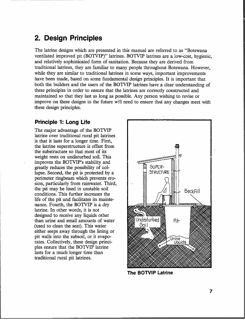
The latrine designs which are presented in this manual are referred to as "Botswanaventilated improited pit (BOTVIP)" latrines. BOTVIP latrines are a low-cost, hygienic,and relatively sophisticated form of sanitation. Because they are derived fromtraditional latrines, they are familiar to many people throughout Botswana. However,while they are similar to traditional latrines in some ways, important improvementshave been made, based on some fundamental design principles. It is important thatboth the builders and the users of the BOTVIP latrines have a clear understanding ofthese principles in order to ensure that the latrines are correctly constructed andmaintained so that they last as long as possible. Any person wishing to revise orimprove on these designs in the future will need to ensure that any changes meet withthese design principles.
Principle 1: Long LifeThe major advantage of the BOTVIPlatrine over traditional rural pit latrinesis that it lasts for a longer time. First,the latrine superstructure is offset fromthe substructure so that most of itsweight rests on undisturbed soil. Thisimproves the BOTVIP's stability andgreatly reduces the possibility of col- u P R-lapse. Second, the pit is protected by a 5TRUCTUREperimeter ringbeam which prevents ero-sion, particularly from rainwater. Third,the pit may be lined in unstable soil BacDPillconditions. This further increases thelife of the pit and facilitates its mainte-nance. Fourth, the BOTVIP is a dry a ... }_-_=_.__
latrine. In other words, it is notdesigned to receive any liquids otherthan urine and small amounts of water Undi~+urbed P&.(used to clean the seat). This watereither seeps away through the lining orpit walls into the subsoil, or it evapo-rates. Collectively, these design princi-sples ensure that the BOTVIP latrinelasts for a much longer time thantraditional rural pit latrines.
The BOTVIP Latrine
7

Principle 2: Ventilation andu-Insect ControlTraditionally designed pit latrines notonly are prone to collapse but also have _____________Odours
two other main disadvantages - theysmell, and they give rise to serious \insect problems. Both these disadvan-tages are substantially reduced in theBOTVIP latrine by the fact that theoffsetting of the superstructuzre also 5ourN i - 02rHpermits the installation of a ventpipe. SIDEThe ventpipe serves a dual purpose. Moveme*First, it carries foul air out of the pitand away from the superstructure. This - VRNTPIPEoccurs mainly because wind blowingacross the top of the ventpipe sucksfoul air out of the pit. Ventilation alsooccurs on still days when the sun heatsthe air in the ventpipe, causing it torise. Second, the ventpipe serves as aninsect trap. Flies and other insects willonly fly into the light. As a result,provided the superstructure is keptreasonably dark, insects will travel outof the dark pit up the ventpipe.However, when they get to the top ofthe ventpipe, they are trapped by theflyscreen, and they eventually die andfall back into the pit. The flyscreen also How the Ventpipe Works*keeps insects from entering the pitthrough the ventpipe.
*Throughout this manual, the ventpipeis shown on the north side of the latrinesuperstructure. In Botswana, which is southof the Equator, this ensures maximumexposure to sunlight and, thus, maximumventilation flow. In countries north of theEquator, the ventpipe should be located onthe south side of the superstructure.
8

Principle 3: Improved Safety I -.The rural BOTVIP latrine is perceivedby its users to be more stable and saferthan traditional designs. First, users are SEAT IW5ERTnot woried that the substructure willcollapse. Second, parents consider it film Bricksafe for their children. Since it has been orestablished that people in Botswana suporprefer to sit rather than squat, a -° aglass-fibre reinforced plastic (grp) seat :- o ,,insert is used. This seat insert is tapered, mwith the upper opening large enough to P recbbnminimize fouling of the bowl (this cutsdown on the amount of water needed Pi i
to keep the bowl clean), and the loweropening small enough to relieve parents'fears that their babies or young children The BOTVIP Seatmight fa'l through into the pit. Thus,the rural BOTVIP latrine is designed tobe used by all age groups.
Principle 4: Self-HelpConstructionResponsibility for the construction ofrural latrines lies with the villagehouseholder, who is assisted by a localVillage Sanitation Assistant (VSA) .Rural latrine designs seek to combinethe use of contemporary and tradi-tional building materials and tech-niques which will be familiar to bothparties. Thus, these designs encourageself-help building practices which notonly reduce costs and constructiontime but also encourage more peopleto use these improved sanitation - -facilities. Constructing the Superstructure
9
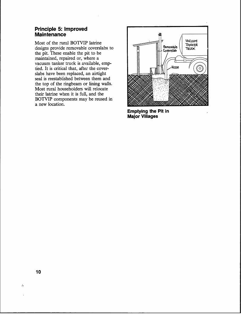
Principle 5: ImprovedMaintenance * VCL
Most of the rural BOTVIP latrine VAC-IFIZdesigns provide removable coverslabs to R juOYable IRUthe pit. These enable the pit to bemaintained, repaired or, where avacuum tanker truck is available, emp-tied. It is critical that, after the cover- oseslabs have been replaced, an airtightseal is reestablished between them andthe top of the ringbeam or lining walls.Most rural householders will relocatetheir latrine when it is full, and theBOTVIP components may be reused ina new location.
Emptying the Pit inMajor Villages
10

3. Constructing the Substructure
This section presents a step-by-step outline of the methods used in constructing threealternative BOTVIP latrine substructures. The first pit is rectangular and unlined andis suitable for use in stable soils, such as heavy clay and rock, which are found wherethe majority of people live. The other two substructures are circular and lirned for usein unstable soils, such as sand, sandy clay or loose clay, which are found in variouslocations throughout Botswana. The decision as to whether or not the pits in aparticular location need to be lined should be made by the District SanitationPlanning Committee, using technical site information supplied by the Departments ofGeological Survey and Water Affairs. The selected designs should also be ratified bythe local Village Developmrent Committee and the Village Sanitation Coordinator.
Most rural BOTVIP latrines are constructed by village householders working inclose collaboration with a local Village Sanitation Assistant (VSA). Quality andefficiency of construction depends, to a large degree, on both parties having a clearidea of their respective roles and responsibilities.
The VSA is responsible for coordinating construction and sharing his expertise withthe householder in order to ensure that the latrine is correctly constructed. If possible,the VSA should keep a written record of progress made on all plots during theconstruction period.
The householder is responsible for supplying labour, local building materials, andwhatever tools he can. Failure by either party to complete his responsibilities on timecan cause serious delays for the other and can undermine the village programme as awhole.
ii

3A. Preparing to Construct the Substructure
Prior to the commencement of construction, both the VSA and the householder must
ensure that they possess, or have access to, the necessary tools they will require to
cormplete their particular tasks.
The Village Sanitation Assistant will n2ed to carry:
* A notebook and a pen* A copy of the design drawings* Stakes and string* A tape measure* A mallet or hammere A spirit level* A trowel* Wire cutters* A satchel or carrying bag
Notebook Trowels
aahes ind ErngI
HaMnmer Wire Cu+ers
Spirit- Level
Orawih3 TapeMeasure
Village Sanitation Assistant's Equipment
12

The Householder should try to provide:
* A water bucket* A wheelbarrow* A spade* A pick* A block mould (suitable for making sand-cement blocks or mud bricks)
Water Bucket
eebbarrrow
Brick or Block Mould
Village Householder's Equipment
In addition, the VSC will need to ensure that all necessary building components and
materials have been, or will be, delivered to the site on time.
Depending on the latrine design, these may include the following:
* Cement, sand and stone* Trapezoidal lining blocks or wire-mesh-and-filter-fabric lining* Reinforcing bars or steel mesh(All of the above to be delivered to the village by ttle District Council)
* Coverslabs(to be constructed off-site, under contract to the District Council, anddelivered to site)
* Plastic ventpipe (if this type is to be used)* Galvanized wire, hessian and flyscreen (for ventpipe)
(to be partially constructed off-site, under contract to the District Council,and delivered to site)
District Council tools and building materials should be stored in a locked temporary
storage room centrally located in the village. The VSC should inspect all tools and
materials before storage to ensure that everything is in good condition.
13

3B. Unlined Rectangular Substructure Built in Stable Soils(BOTVIP A)
This subsection describes an unlined rectangular (BOTVIP A) substructure which maybe constructed in very stable soils such as rock, heavy clay or decomposed granite.The fact that a lining wall is not required obviously reduces the cost of thesubstructure. However, unlined pits should be constructed only in locations designatedby the District Sanitation Planning Committee.
Step 1: Location, Orientationand Staking BO.V0P2. o meWces SUBSTRUlCrUREThe latrine substructure should be Trelocated by the householder, in closecollaboration with the VSA. Generallyspeaking, the latrine should be located Plottowards the rear of the plot. Where no Boudaydoor is to be provided on the super-structure, the entry should preferablynot face east or west where the morningor evening sunlight can penetrate theinterior of the substructure and soencourage insects to leave the pitthrough the latrine seat instead of upthe ventpipe. It is also important toensure that the entry will not be directly Locating the Rectangular Substructurevisible to either passersby or neighbour- -
ing plots. Preferably, the entry shouldface the house. PREFERRED
The latrine should be located at least ORIENTATION2 metres from existing trees or over- 0 pbhanging branches in order to maintain OCnfcptabnproper ventilation through the ventpipe. CMOrinta+onIdeally, the ventpipe should be located NODYrT- (N+h door)on the north side to ensure that it isheated by the sun on still days; thishelps maintain proper ventilation.
Once the latrine has been correctlylocated and oriented, the VSA shiould ACceptiablestake out an area 1100 mm wide and Oritntabbn1800 mm long and run a string or (wi+h door) unacceptableground-line between the stakes. Alter- iOrfeniabbnnatively, a preconstructed rectangularwood frame or piece of canvas of thesedimensions may be used for locating the Orientation of Ventpipestakes.
14Note: Throughout this manual, the ventpipe is shown on the northside of the latrine superstructure. In Botswana, which is south ofthe Equator, this ensures maximum exposure to sunlight and somaximum ventilation flow. In countries north of the Equator, theventpipe should be located on the south side of the superstructure.
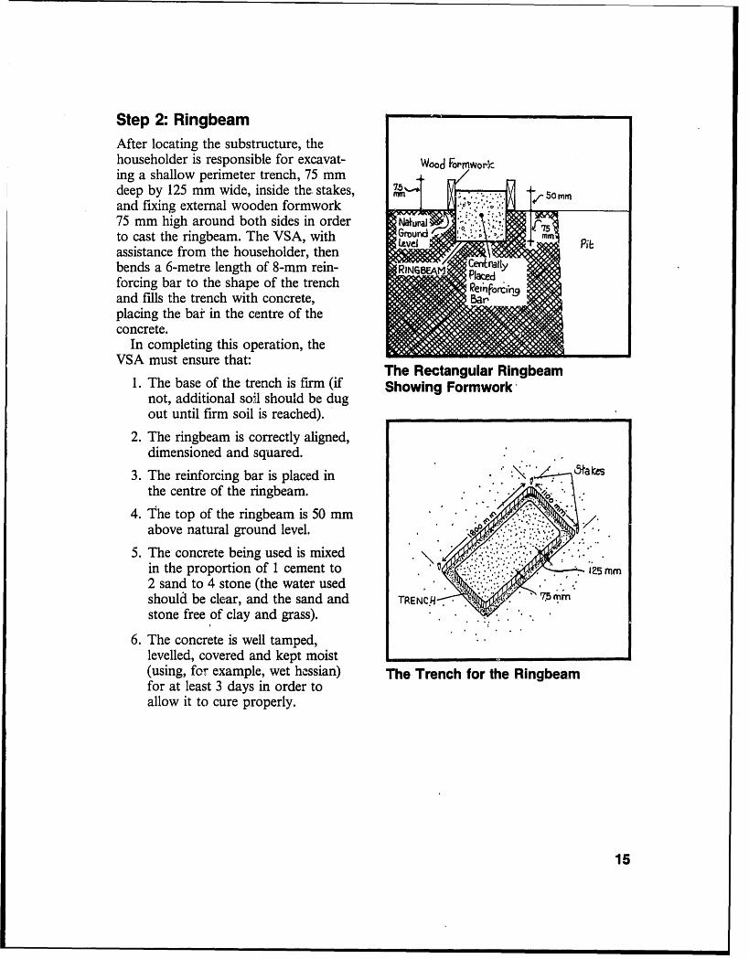
Step 2: RingbeamAfter locating the substructure, thehouseholder is responsible for excavat- Woo Fortnworking a shallow perimeter trench, 75 mm /deep by 125 mm wide, inside the. stakes, -
and fixing external wooden formwork75 mm high around both sides in order Iau1to cast the ringbeam. The VSA, with Grourd mm
assistance from the householder, thenbends a 6-metre length of 8-mm rein- RrN6V3 rallyac cforcing bar to the shape of the trench BIand fills the trench with concrete,Baplacing the bar in the centre of theconcrete.
In completing this operation, theVSA must ensure that: The Rectangular Ringbeam
1. The base of the trench is firm (if Showing FormRworknot, additional so:,l should be dugout until firm soil is reached).
2. The ringbeam is correctly aligned,dimensioned and squared.
3. The reinforcing bar is placed in .ta esthe centre of the ringbeam.
4. The top of the ringbeam is 50 mmabove natural ground level.
5. The concrete being used is mixedin the proportion of 1 cement to :? .mm
2 sand to 4 stone (the water usedshould be clear, and the sand and TREN C..H 7. (rpm
stone free of clay and grass). *r
6. The concrete is well tamped, .
levelled, covered and kept moist .
(using, for example, wet hessian) The Trench for the Ringbeamfor at least 3 days in order toallow it to cure properly.
15
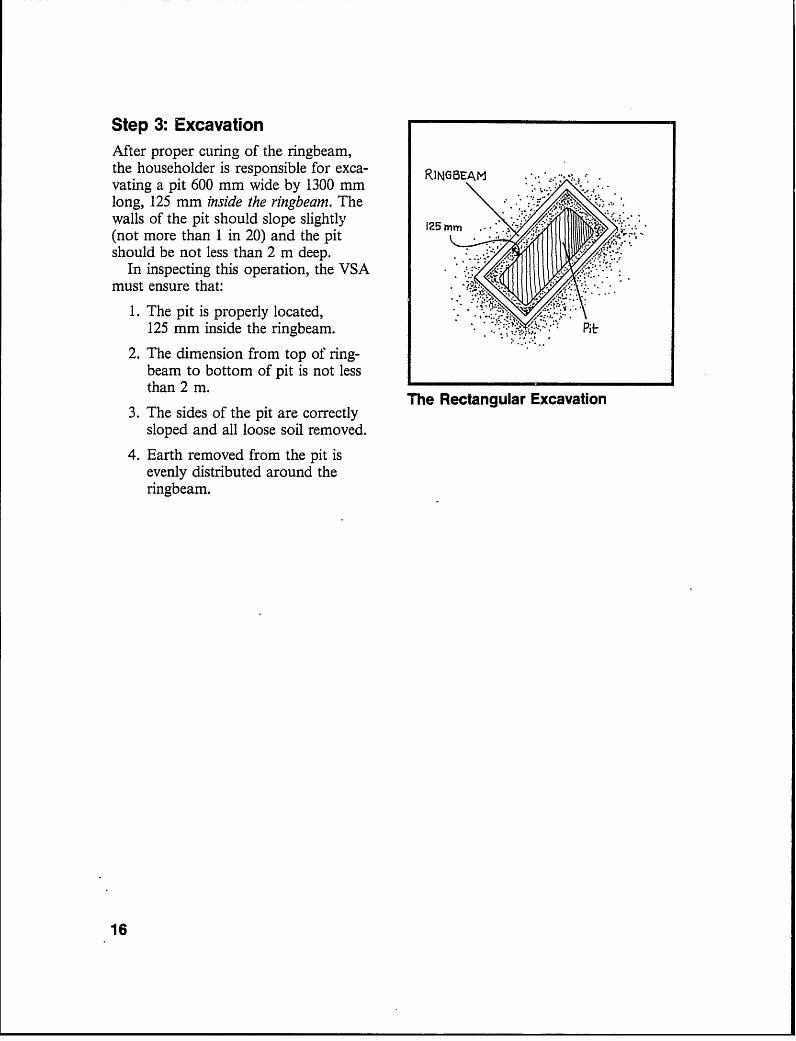
Step 3: ExcavationAfter proper curing of the ringbeam,the householder is responsible for exca- RJNGBEAMvating a pit 600 mm wide by 1300 mmlong, 125 mm inside the ringbeam. The ..
walls of the pit should slope slightly m(not more than 1 in 20) and the pitshould be not less than 2 m deep.
In inspecting this operation, the VSAmust ensure that:
1. The pit is properly located, .X.;
125 mm inside the ringbeam. Pit
2. The dimension from top of ring-beam to bottom of pit is not lessthan 2 m.
The Rectangular Excavation3. The sides of the pit are correctly
sloped and all loose soil removed.
4. Earth removed from the pit isevenly distributed around theringbeam.
16
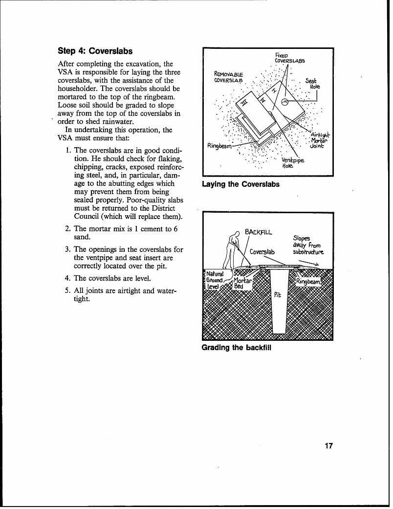
Step 4: Coverslabs FIXED
After completing the excavation, the COVERsLAsVSA is responsible for laying the three REMOvAB.icoverslabs, with the assistance of the COVERSLAB . | eahouseholder. The coverslabs should bemortared to the top of the ringbeam.Loose soil should be graded to slope . \ Iaway from the top of the coverslabs inorder to shed rainwater.
In undertaking this operation, theVSA must ensure that: .. ... Athfi
1. The coverslabs are in good condi- . .' **
tion. He should check for flaking, . Veni'pechipping, cracks, exposed reinforc- ..
ing steel, and, in particular, dam-age to the abutting edges which Laying the Coverslabsmay prevent them from beingsealed properly. Poor-quality slabsmust be returned to the DistrictCouncil (which will replace them).
2. The mortar mix is 1 cement to 6 BACKFILLsand. 5lope5
fw 21 / way from3. The openings in the coverslabs for Coverslab subsruchurm
the ventpipe and seat insert arecorrectly located over the pit.
4. The coverslabs are level. Gnd rratur
5. All joints are airtight and water-tight.
Grading the backfill
17

3C. Lined Circular Substructures Built in Unstable Soils(BOTVIP B)
This section describes two alternative circular lined substructures which may beconstructed where unstable soils (such as sand, sandy-clay or loose gravelly-clay) arefound. These are particularly suitable for use in the Kalahari. The linings protect thepits from collapsing while at the same time permitting the seepage of urine and othersmall amounts of liquid into the adjacent soil.
(i) Circular Substructure with Masonry Lining
Step 1: Location, Orientationand Staking 2.0 metres Bor\IP
The latrine substructure should be AUBSTRUCTURR
located by the householder, in closecollaboration with the VSA. Generally ... PIoU
speaking, the latrine should be located YAR D Boundary
towards the rear of the plot. Where nodoor is to be provided on the super- i
structure, the entry should preferablynot face east or west where the morning .or evening sunlight can penetrate theinterior of the substructure and soencourage insects to leave the pit e.through the latrine seat instead of upthe ventpipe. It is also important to . __
ensure that the entry will not be directly Locating the Circular Substructurevisible to either passersby or neighbour-ing plots. Preferably, the entry shouldface the house.
The latrine should be located at least2 metres from existing trees or over-hanging branches in order to maintainproper ventilation through the ventpipe.Ideally, the ventpipe should be locatedon the north side to ensure that it isheated by the sun on still days; thishelps maintain proper ventilation.
Once the latrine has been correctlylocated and oriented, the VSA shouldmeasure and mark out a circle 1250mm in diameter, using a central stakeand a piece of string with a nail on the
18
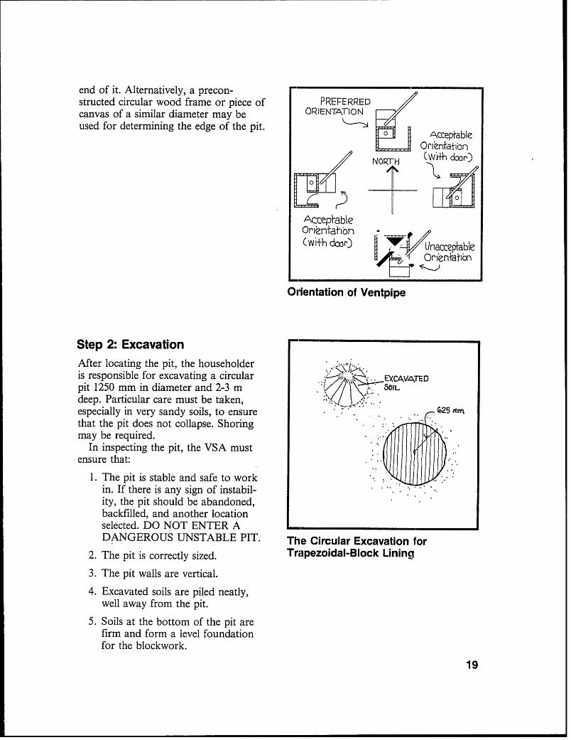
end of it. Alternatively, a precon-structed circular wood frame or piece of PREFERREDcanvas of a similar diameter may be ORIENTATIONused for determining the edge of the pit. Adcceptable
____ ROrfenfaibbn
X9 Nr oP (W+h door)
AcceptableOrlnntatibn(with door) y linacceptable
H 4. Or(enfatbbn
Orientation of Ventpipe
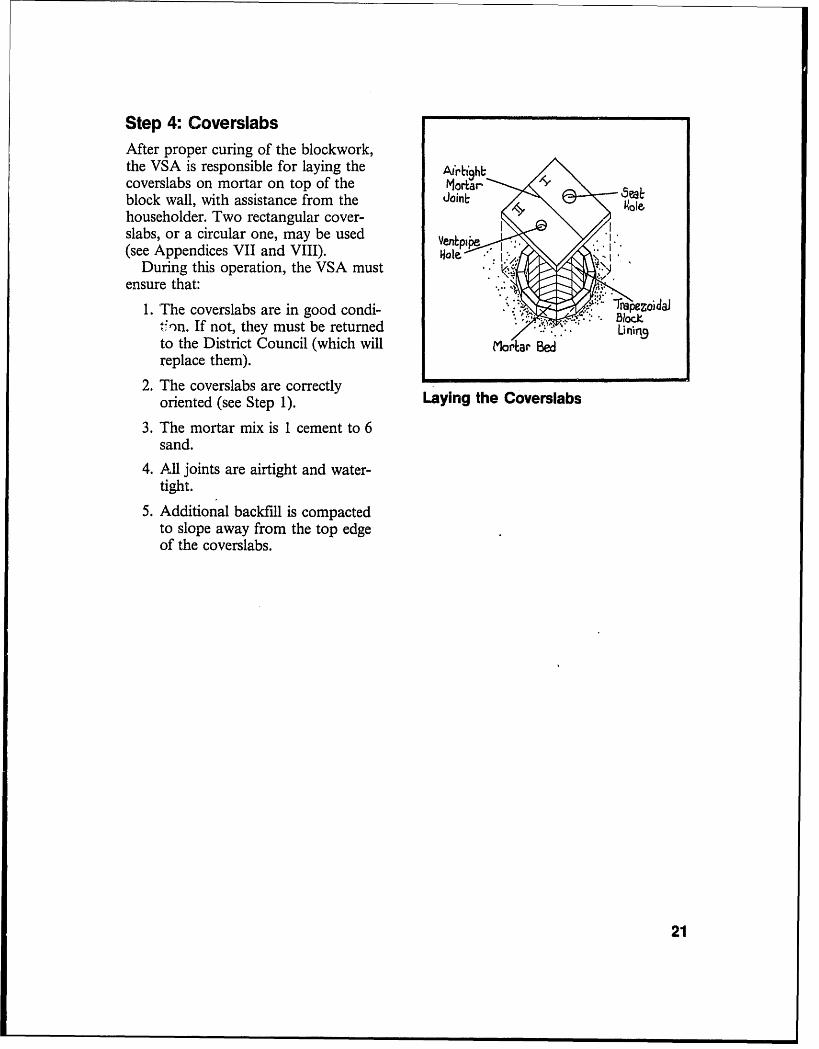
Step 2: Excavation --
After locating the pit, the householderis responsible for excavating a circular EXCAVATEDpit 1250 mm in diameter and 2-3 m SOILdeep. Particular care must be taken,especially in very sandy soils, to ensure G-25 mmthat the pit does not collapse. Shoringmay be required.
In inspecting the pit, the VSA mustensure that:
1. The pit is stable and safe to workin. If there is any sign of instabil-ity, the pit should be abandoned,backfilled, and another locationselected. DO NOT ENTER A -DANGEROUS UNSTABLE PIT. The Circular Excavation for
2. The pit is correctly sized. Trapezoidal-Block Lining
3. The pit walls are vertical.
4. Excavated soils are piled neatly,well away from the pit.
5. Soils at the bottom of the pit arefirm and form a level foundationfor the blockwork.
19

Step 3: Blockwork and BackfillFollowing inspection of the pit by theVSA, the householder is responsible forconstructing the lining of the specially-made trapezoidal blocks (see AppendixV). The first course should be laid outloosely, levelled by the VSA, and thenmortared. The householder then buildsthe lining wall up to just above groundlevel. On completion of the wall, thehouseholder should backfill the spacebetween the wall and the edge of theexcavation with sandy soil or finegravel. The top 500 mm should be mrn
backfilled with clay or a weak soil- v mm
cement mixture (10:1).In inspecting this stage of construc- Levelling the First Course of
tion, the VSA must ensure that: Trapezoidal Blocks
1. Good-quality trapezoidal blocksare used throughout.
2. The mortar mix used in the firstcourse is 1 cement to 6 sand. lbp 3 Courses Morlared
I /N Sbopes awayI3. All joints are left open except for s 50< sub*fum-
the top three courses which must mbe fully sealed (with mortar mixed N Gral
in the proportion of I cement to 6 aAlerFLL
sand) to prevent rainwater from (Soi[cemententering the pit.
4. The top of the wall extends about50 mm above natural ground DRAINING
level. | | ILL(gravel or
5. When the blockwork is completed, ,Sndthe earth at the bottom of the pit jrj CoUrbe aoriaPdis loosened with a pick and allsurplus mortar removed. Backfilling the Excavation
6. Backfill is compacted and slopesaway from the top of the wall.
20
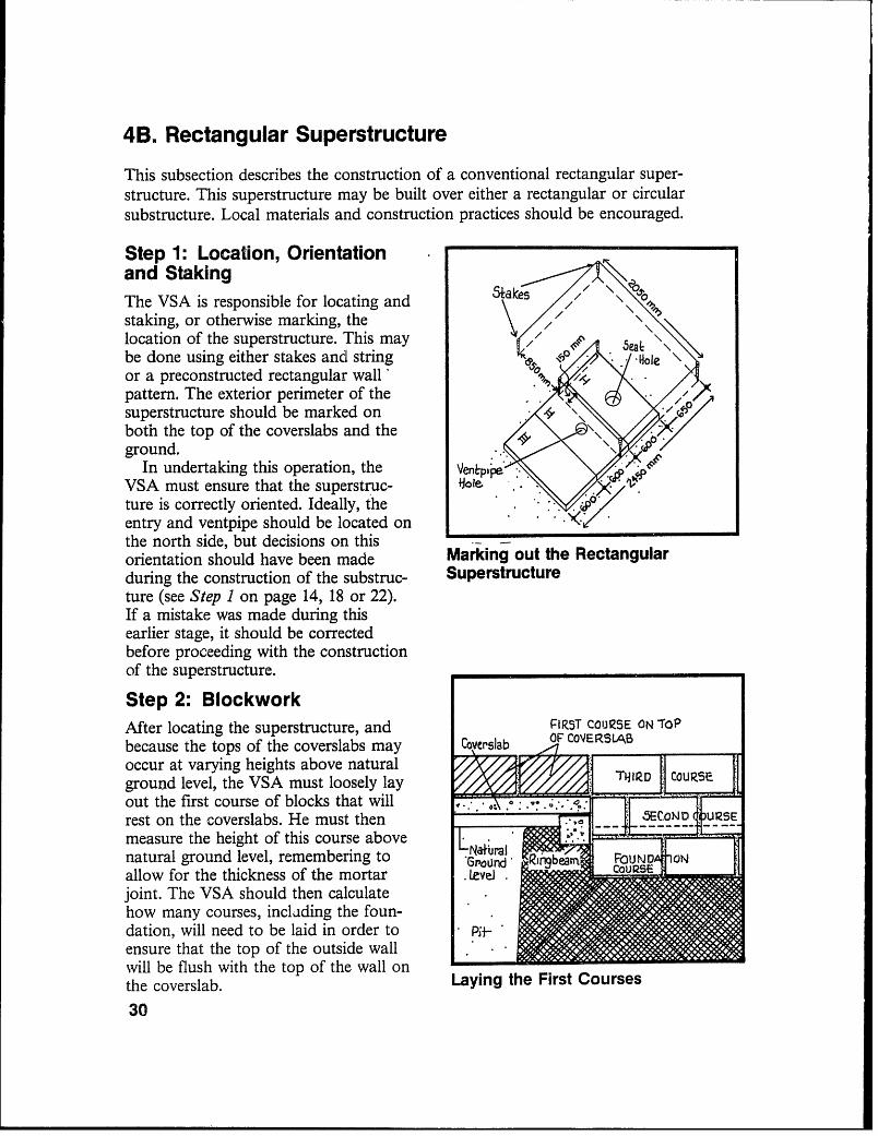
Step 4: CoverslabsAfter proper curing of the blockwork,the VSA is responsible for laying the Arb9htAcoverslabs on mortar on top of the Mortarblock wall, with assistance from the Joinl:householder. Two rectangular cover-slabs, or a circular one, may be used(see Appendices VII and VIII). *ale
During this operation, the VSA mustensure that:
1. The coverslabs are in good condi- . / pezoidalhn. If not, they must be returned U ¢ B.Lniq
to the District Council (which will (lorar Bedreplace them).
2. The coverslabs are correctlyoriented (see Step 1). Laying the Coverslabs
3. The mortar mix is 1 cement to 6sand.
4. All joints are airtight and water-tight.
5. Additional backfill is compactedto slope away from the top edgeof the coverslabs.
21

(ii) Circular Substructure with Wire-lMesh Lining
Step 1: Location, Orientationand Staking 2.0 mehres Baro I p
The latrine substructure should be U8STRUCTUJRE.located by the householder, in closecollaboration u lithe VSA. Generally p : lo.speaking, the latrine should be located - : YARD 8ounda~y
towards the rear of the plot. Where no .door is to be provided on the super-structure, it is important that the entryshould not face east or west where themorning or evening sunlight can pene-trate the interior of the substructure andso encourage insects to leave the pit e 9through the latrine seat instead of upthe ventpipe. It is also important toensure that the entry will not be directlyvisible to either passersby or neighbour- Locating the Circular Substructureing plots. Preferably, the entry shouldface the house.
The latrine should be located at least PIREPERRED2 metres from existing trees or over- ORIENTATIONhanging branches in order to maintain A ebproper ventilation through the ventpipc. nAccepfableIdeally, the ventpipe should be located Ud OnlenlrIonon the north side to ensure that it is NORTH (Wi+h door)heated by the sun on still days; this Xhelps to maintain proper ventilation.
Once the latrine has been correctlylocated and oriented, the VSA should rmeasure and mark out two circles of Atceptable900 mm and 1025 mm diameters 0rltntatibnrespectively, using a central stake and a (Wi±h door) / , /'/JnaccePtablepiece of string with a nail on the end of H r ' Orien+ nit. Alternatively, a preconstructed circu-lar frame of a similar diameter may beused to determine the edge of the pit. Orientation of Ventpipe
22

Step 2: ExcavationAfter locating the latrine, the house-holder is responsible for excavating acircular pit 950 mm in diameter and EXCAVAEOL2200 mm deep. Particular care must betaken, especially in very sandy soils, to $475 minensure that the pit does not collapse.Shoring may be required.
In inspecting the pit, the VSA must jensure that:
1. The pit is stable and safe to workin. If there is any sign of instabil-ity, the pit should be abandoned,backfilled, and another locationselected. DO NOT ENTER ADANGEROUS UNSTABLE PIT. Circular Excavation for Wire-Mesh-
2. The pit is the right size and the and-Filteir-Fabric Liningwalls are vertical.
3. The pit is 2200 mm deep.
4. Excavated soils are piled neatly,well away from the pit.
Step 3: Lining and BackfillAfter completing the excavation, the taturaJhouseholder is responsible for placing Ground , irc Eridsthe wire-mesh-and-filter-fabric frame VeJ . -9omm-a(see Appendix VI) in the pit, withassistance from the VSA. They must PERVioensure that the top of the frame extendsto ground level. Once the lining is WiRE- ES-r;'j.o linstalled, the householder should back- AND- FILTER-fill the small space between the frame FA3RIc Pr -and the edge of the excavation with L I RAING c
sandy soil or fine gravel. The top BACXFILLX500 mm should be backfilled with clay (9avcl or
or a weak soil-cement mixture (10:1).In inspecting this operation, the VSA
must ensure that:1. The top ring of the frame is at Placing the Wire-Mesh Lining
ground level, and the wire ends in the Excavationextend straight up, 100 mm aboveground level.
2. Backfill has been completed correctly.
23

Step 4: RingbeamFollowing placement of the lining and Wood Formwork
backflll, the householder excavates atrench, 125 mm wide by 75 mm deep, TU5^1t WIRE-MESH-AND-
around the periphery oftepi.Hthen bends the top of the wire-mesh 3a 4
frame outwards so that it projects into Ground WIien
the ringbeam excavation. The VSA thenpours a 125-mm-square ringbeamaround the wire ends, using them as Impervious - - --
reinforcement. The ringbeam should -k-rest flush against the lining which actsas a shutter.
In supervising this operation, the | eVSA must ensure that:
1. The ringbeam trench is correctly Pouring the Circular Ringbeamdimensioned.
2. The ringbeam concrete is rnixed at1 cement to 2 sand to 4 stonc, andis well compacted.
3. The wire ends extend into theringbeam and are secured.
4. The ringbeam is permitted to curefor at least 3 days. It may be keptdamp during the curing period,using wet hessian, fox-example.
24

Step 5: CoverslabsFollowing proper curing of the ring-beam, the VSA is responsible for 5ea/placing and securing the coverslabs to Hole Venipioethe top of the ringbeam, with assistancefrom the householder. Two rectangular Air+i9hl;coverslabs, or a circular one, may be MorFarused (see Appendices VII and VIII). n t 14 i
During this operation, the VSA mustensure that:
1. The coverslabs are in good condi-tion. If not, they must be returned rEarto the District Council (which will 8edRE-MESI4 -ANe-replace them). FILTEe- FABec
them).LINING2. The coverslabs are correctly
oriented (see Step 1). Laying the Coversiabs
3. The mortar mix is 1 cement to 6sand.
4. All joints are airtight andwatertight. -CI
5. Additional backfill is compactecl Slopesaayto slope away from the top edge Coverslab fsronof the coverslabs. su*Xcku\
Grading the Backfill
25

4. Constructing the Superstructure
This section presents a step-by-step outline of the methods used in constructing twoalternative BOTVIP latrine superstructures - one is rectangular, built using eithertraditional or contemporary methods and materials; the other is round, using onlytraditional methods, and traditional or contemporary materials. Either of these designscan be erected on any of the substructures which were presented in the previoussection (see Appendices I-IV). As there are a large number of superstructure designswhich are equally acceptable, these two should be viewed only as typical examples.Above all, it is important that the Village Sanitation Assistants (VSAs) informhouseholders that they may use a wide variety of building materials. Householdersshould be encouraged to use readily available local building materials which they canafford. These may include traditional materials (e.g., thatch, reeds, sun-driedmud-brick or poles) as well as contemporary ones (e.g., corrugated-iron roof sheets orsanQ-cement blocks). However, regardless of the design or materials used, thesuperstructure must be ventilated and kept reasonably dark inside to ensure that fliesleave the pit up the ventpipe instead of through the seat.
As with the substructure, the superstructure is constructed by the householder,working in close collaboration with the VSA. It is important that both parties clearlyunderstand their respective roles and responsibilities in order to avoid delays. Everyeffort should be made to complete the superstructure as soon as possible after thesubstructure is finished. The VSAs should visit village plots on a regular basis duringconstruction periods to help people with any problems which may arise. They shouldalso keep a record of the householders' progress.
26

4A. Preparing to Construct the Superstructure
Prior to the commencement of construction, both the VSA and the householder mustensure that they possess, or have access to, the necessary tools they will need.
The Village Sanitation Assistant will need:
* Wall pattern (optional)* A tape measure* A hammer* A spirit level* Trowe1N (for bricklaying and plastering)* A spade* Stakes and string* A satchel or carrying bag
&rJ-akesand 5trihA
Tape Measure '4Trwels
Hammer
-rspade arpit Level
Village Sanitation Assistant's Equipment
27

The Householder will need to possess, or have access to:
* A brick or block mould* A hammer* A tape measure* Trowels (for bricklaying and plastering)* Wire cutters* A saw* A plastering brush (optional)
Bre& or Block
Wi-re CL3jers
Hammer Trowels Tape M ea sy
Village Householdees Equipment
In addition, the householder will need to purchase, seek out or make all the necessarybuilding materials and assemble these before construction begins. These materials mayinclude:
* Sand-cement blocks or mud-bricks* Wood braces, wall plates or rafters* Door frame (optional)o CementC Corrugated-iron or asbestos roof sheets, or thatch* Plaster* Paint* Galvanized wire* Nails and screws
Finally, the VSAs must ensure that the ventpipes, flyscreens and seat inserts havebeen, or will be, delivered to individual plots on time.
28

Bei'cks or Blocks
'Door Frame
Roo Poles
aICemen RooEFng S3heets
W?ire and NailsThatch
Superstructure Materials Supplied by the Householder
29
4B. Rectangular Superstructure
This subsection describes the construction of a conventional rectangular super-structure. This superstructure may be built over either a rectangular or circularsubstructure. Local materials and construction practices should be encouraged.
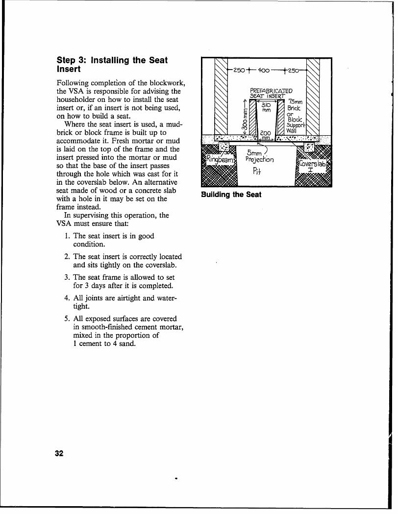
Step 1: Location, Orientationand StakingThe VSA is responsible for locating andstaking, or otherwise marking, thelocation of the superstructure. This maybe done using either stakes and string Holeor a preconstructed rectangular wall'pattern. The exterior perimeter of thesuperstructure should be marked onboth the top of the coverslabs and theground.
In undertaking this operation, the Venkpij ,VSA must ensure that the superstruc- -
ture is correctly oriented. Ideally, theentry and ventpipe should be located onthe north side, but decisions on thisorientation should have been made Marking out the Rectangularduring the construction of the substruc- Superstructureture (see Step 1 on page 14, 18 or 22).If a mistake was made during thisearlier stage, it should be correctedbefore proceeding with the constructionof the superstructure.
Step 2: BlockworkAfter locating the superstructure, and FiRST COURSE ON IoPbecause the tops of the coverslabs may CoVerslab OF CO0JERSLABoccur at varying heights above natural T/IIZD COoI/a//Sground level, the VSA must loosely lay j THID COURSEout the first course of blocks that willrest on the coverslabs. He must then .ECoNi URSEmeasure the height of this course abovenatural ground level, remembering to N*Gural b POUNP 1OWallow for the thickness of the mortar . LeveJ . ljoint. The VSA should then calculatehow many courses, inclading the foun-dation, will need to be laid in order to Pi3 -ensure that the top of the outside wallwill be flush with the top of the wall onthe coverslab. Laying the First Courses30

The VSA commences construction byexcavating a trench for the foundationwhich may be formed by either concreteor a first course of blocks. Once the Rear WalJfoundation has set, he should continueto build up the wall until it incorporatesthe first course on the coverslab. Thehouseholder should take over after this Walland complete the walls to roof level.The top of the front wall should behigher (about 2.0 m) than the top of the Aearear wall (about 1.8 m) in order to verslabsupport a roof which will drain to therear of the superstructure. A smallventilation gap may be left in the rearwall. If desired, a door frame may beinstalled (see Step 6). Constructing the Superstructure
Where mud-bricks and plaster are Wallsused, the bottom 1 m of the exteriorwall should be plastered (using a mortarmixture of 1 cement to 6 sand) andcovered with a cement wash to protectagainst rain damage.
In undertaking and inspecting this een . Vn1-:lat6nostage of construction, the VSA must .oO6npal)ensure that: . pil naII
1. Blocks being used are of reason-able quality. They should not .break if dropped on the ground ..
from chest height. r
2. Blockwork is plumb and level. r eis5
3. The mortar mix is 1 cement to 6sand.
4. The ventilation gap is well located.
5. The walls are allowed to set for atleast 3 days. Completing the Superstructure
6. Provision is made for tying the Wallsrafters and the ventpipe to theblockwork.
31
Step 3: Installing the Seat .Insert -250 to -00 250-o
Following completion of the blockwork,the VSA is responsible for advising the PREFABRICATEDhouseholder on how to install the seat 5EAT IISE r 75mrinsert or, if an insert is not being used,on how to build a seat.E
Where the seat insert is used, a mud- E pporbrick or block frame is built up to ZOO
accommodate it. Fresh mortar or mud .. : . ... . : m : .
is laid on the top of the frame and the 5mminsert pressed into the mortar or mud IL rn PrjecAionso that the base of the insert passes L+through the hole which was cast for itin the coverslab below. An alternativeseat made of wood or a concrete slab Building the Seatwith a hole in it may be set on theframe instead.
In supervising this operation, theVSA must ensure that:
1. The seat insert is in goodcondition.
2. The seat insert is correctly locatedand sits tightly on the coverslab.
3. The seat frame is allowed to setfor 3 days after it is completed.
4. All joints are airtight and water-tight.
5. All exposed surfaces are coveredin smooth-finished cement mortar,mixed in the proportion of1 cement to 4 sand.
32

Step 4: Roof and DrainageAfter completing the seat, the house-holder is responsible for constructing Ra,nwawerthe roof. Wood wall plates should bewired to the top of the front and rear 56I-Cemenl:walls, and corrugated-iron or asbestos M11turesheets (cut to the correct size - 2000 ( r.mm by 1500 mm) fixed to the plates. prdecfivXThe use of rafters is optional. A hole Si'onewoj;should be cut in the roof to allow theventpipe to extend through it. All.urplus soil should be graded, smoothedand compacted to provide good drain-age away from the latrine.
In inspecting this stage of construc-tion, the VSA must ensure that:
Roofing the Superstructure1. The wall plates are well secured to
the top of the walls.
2. The roof sheets are properlysecured to the plates (or rafters).
3. The roof will drain to the rear ofthe superstructure.
33

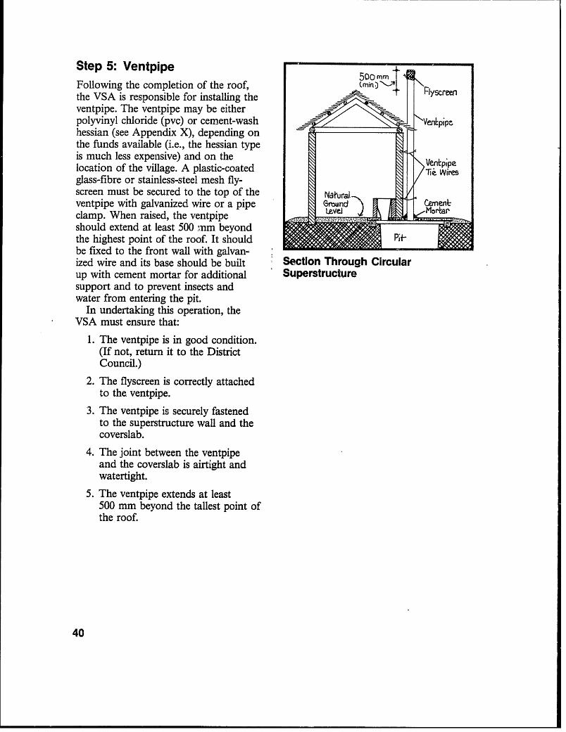
Step 5 VentpipeFollowing the completion of the roof,the VSA is responsible for installing theventpipe. The ventpipe may be eitherpolyvinyl chloride (pvc) or cement-wash 50Omrhessian (see Appendix X), depending onthe funds available (i.e., the hessian typeis much less expensive) and on the Ve4pipelocation of the village. A plastic-coatedglass-fibre or stainless-steel mesh fly- Venr+i Iaibnscreen must be secured to the top of theventpipe with galvanized wire or a pipe (opf-inal) /Tei Wiresclamp. When raised, the ventpipe N
should extend at least 500 mm beyondthe highest point of the roof. It should Cemen6be fixed to the front wall with galvan-ized wire and its base should be builtup with cement mortar for additional Soil-Cerrenksupport and to prevent insects and Nbxurewater from entering the pit. (w4h
in undertaking this oper tion, the opttbn8iVSA must ensure that: &I'onework)
1. The ventpipe is in good condition.(If not, return it to the DistrictCouncil.)
2. The flyscreen is correctly attachedto the ventpipe.
3. The ventpipe is securely fastened Section through the Rectangularto the superstructure wall and the Superstructurecoverslab.
4. The joint between the ventpipeand the coverslab is airtight andwatertight.
5. The ventpipe extends at least500 mm beyond the tallest pointof the roof.
34
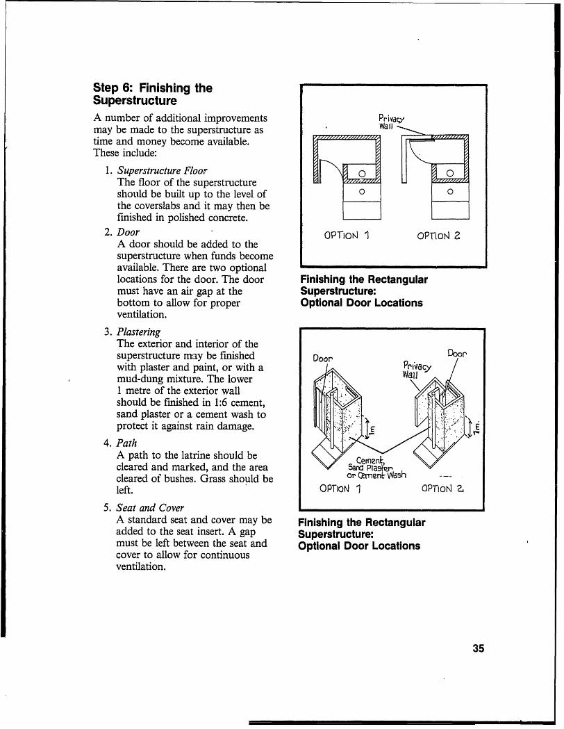
Step 6: Finishing theSuperstructureA number of additional improvements Privacymay be made to the superstructure astime and money become available.These include:
1. Superstructure Floor OThe floor of the superstructure 0should be built up to the level ofthe coverslabs and it may then befinished in polished concrete.
2. Door oPmorK I OPFioN 2A door should be added to thesuperstructure when funds becomeavailable. There are two optionallocations for the door. The door Finishing the Rectangularmust have an air gap at the Superstructure:bottom to allow for proper Optional Door Locationsventilation.
3. PlasteringThe exterior and interior of thesuperstructure may be finished Door Doorwith plaster and paint, or with a PriYaimud-dung mixture. The lower1 metre of the exterior wallshould be finished in 1:6 cement,sand plaster or a cement wash toprotect it against rain damage.
4. PathA path to the latrine should be JCeenNcleared and marked, and the area Sand PIasrcleared of bushes. Grass should be or (ITnflt 5hleft. OPTioN 1 OPToIN a
5. Seat and CoverA standard seat and cover may be Finishing the Rectangularadded to the seat insert. A gap Superstructure:must be left between the seat and Optional Door Locationscover to allow for continuousventilation.
35

4C. Circular Superstructure
This subsection describes the construction of a circular superstructure. This type ofsuperstructure may be built on either a rectangular or a circular substructure. Thedesign is based on traditional construction techniques and can be built using eithertraditional or contemporary building materials.
Step 1: Location, Orientationand Staking
NailThe VSA is responsible for locating andstaking, or otherwise marking, the Centre I 15-mm V °location of the superstructure. This may FiIedbe done using either stakes and a string State I. l lor a preconstructed circular wall pattern. (Qadi6s \ enh-eThe exterior perimeter of the super- 850mm) XFlx estructure should be marked on both the -ketop of the coverslabs and the ground. * (Radius
In undertaking this operation, 'the .450 mm)VSA must ensure that the superstruc - VtPlpe * pi. p5ea}ture is correctly oriented. loie . W; oI
Ideally, the entry and ventpipe shouldbe located on the north side, butdecisions on this orientation should Marking out thie Circularhave been made during the construction Superstructure!of the substructure (see Step 1 on page14, 18 or 22). If a mistake was madeduring this earlier stage, it should becorrected before proceeding with theconstruction of the superstructure. PIRST COUIZSE ON foP
Govcrslab OF COVERSLAB
Step 2: Blockwork TeI E D COURSE
After locating the superstructure, and ______.__
because the tops of the coverslabs may -ECOND URSEoccur at varying heights above naturalground level, the VSA must loosely lay Nturaluout the first course of blocks or bricks Podeljd CitObeam ROUNDR Sthat will rest on the coverslabs. Hemust then measure the height of thiscourse above ground level, remembering .
to allo:v' for the thickness of the mortarjoint. The VSA should then calculatehow many courses, including the foun- Laying the First Coursesdation, will need to be laid in order to
36

ensure that the top of the outside wallwill be flush with the top of the wall onthe coverslab.
The VSA commences construction byexcavating a trench for the foundationwhich may be formed by either concreteor a first course of blocks or bricks.Once the foundation has set, he shouldcontinue to build up the wall until itincorporates the first course on thecoverslab. The householder should takeover after this and complete the walls to Coversiab*roof level. The top of the front wallshould be higher (about 2.0 m) than thetop of the rear wall (about 1.8 m) inorder to support a roof which will dfain -to the rear of the superstructure. A Constructing the Circularsmall ventilation gap may be left in the Superstructure Wallrear wall. If desired, a door frame maybe installed (see Step 6).
Where mud-bricks and plaster areused, the bottom 1 metre of the exteriorwall should be plastered (using a mortar Venrdlatf,nmixture of 1 cement to 6 sand) and Gapcovered with a cement wash to protect. (q:tional)against rain damage. : ..
In undertaking and inspecting thisstage of construction, the VSA must : lensure that: / *..., S
1. Blocks or bricks being used are of lie Wii's , V a
reasonable quality. They should 5 .not break if dropped on the t o >ground from chest height.
2. Blockwork or brickwork is plumband level.
3. If cement mortar is used, the mixis 1 cement to 6 sand. Mud mortar Completing the Superstructuremay vary according to local Wallcustom.
4. The ventilation gap is well located.
5. The walls are allowed to set for atleast 3 days.
6. Provision is made for tying theventpipe to the blockwork.
37

Step 3: Installing the SeatInsert 250 -i--o 0 250-o
Following completion of the blockworkor brickwork, the VSA is responsible PREFABRICATEDfor advising the householder on how to E INSER7 75mminstall the seat insert or, if an insert is 131c,not being used, on how to build a seat. E
Where the seat insert is used, a mud- \ Suppor&brick or block frame is built up to 201accommodate it. Fresh mortar or mudis laid on the top of the frame and theinsert pressed into the mortar or mud R&ibearn Prioec+ton raso that the base of the insert passes pi+through the hole which was cast for it inthe coverslab below. An alternativeseat made of wood or a ¢oncrete slab Building the Seatwith a hole in it may be set on theframe instead.
In supervising this operation, theVSA must ensure that:
1. The seat insert is in goodcondition.
2. The seat insert is correctly located,and sits tightly on the coverslab.
3. The seat frame is allowed to setfor 3 days after it is completed.
4. All joints are airtight and water-tight.
5. All exposed surfaces are coveredin smooth-finished cement mortar,mixed in the proportion of1 cement to 4 sand.
38

Step 4: Roof and DrainageAfter completing the seat, the house-holder is responsible for constructingthe roof. Typically, this can be made of mfxfrethatch lashed to a pole roof frame in (WAthe traditional fashion. The householder pre.tinamay wish to hire a professional thatcher onewor Xa ihwnaterin the village to build the roof for him.All surplus soil should be graded,smoothed and compacted to providegood drainage away from the latrine.
In inspecting this stage of construc-tion, the VSA must ensure that:
1. The roof frame is well secured tothe top of the wall.
2. The thatch is well laid. Roofing the Circular
3. The roof will drain away from the Superstructuresuperstructure walls.
39
Step 5: Ventpipe 500rtFollowing the completion of the roof,the VSA is responsible for installing theventpipe. The ventpipe may be eitherpolyvinyl chloride (pvc) or cement-wash \hessian (see Appendix X), depending onthe funds available (i.e., the hessian typeis much less expensive) and on the V plocation of the village. A plastic-coated >Vesglass-fibre or stainless-steel mesh fly-screen must be secured to the top of the Natura ,ventpipe with galvanized wire or a pipe Grsnd Xemen6clamp. When raised, the ventpipeshould extend at least 500 nm beyondthe highest point of the roof. It should | gbe fixed to the front wall with galvan-ized wire and its base should be built Section Through Circularup with cement mortar for additional Superstructuresupport and to prevent insects andwater from entering the pit.
In undertaking this operation, theVSA must ensure that:
1. The ventpipe is in good condition.(If not, return it to the DistrictCouncil.)
2. The flyscreen is correctly attachedto the. ventpipe.
3. The ventpipe is securely fastenedto the superstructure wall and thecoverslab.
4. The joint between the ventpipeand the coverslab is airtight andwatertight.
5. The ventpipe extends at least500 mm beyond the tallest point ofthe roof.
40

Step 6: Finishing theSuperstructureA number of additional improvementsmay be made to the superstructure astime and money become available.These include:
1. Superstructure Floor ,;:,The floor of the superstructureshould be built up to the level ofthe coverslabs and it may then be Cemtfinished in polished concrete. ,en
2. Door or' Cejnent-A door may be added to the washsuperstructure when funds becomeavailable. The door must have anair gap at the bottom to allow for Finishing the Circularproper ventilation. Superstructure
3. PlasteringThe exterior and interior of thesuperstructure may be finishedwith plaster and paint, or with amud-dung mixture. The lower1 metre of the exterior wall should befinished in 1:6 cement, sand plaster,or a cement wash to protect it againstrain damage.
4. PathA path to the latrine should becleared and marked, and the areacleared of bushes. Grass should beleft.
5. Seat and CoverA standard seat and cover may beadded to the seat insert. A gapmust be left between the seat andcover to allow for continuousventilation.
41
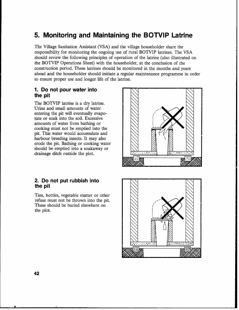
5. Monitoring and Maintaining the BOTVIP LatrineThe Village Sanitation Assistant (VSA) and the village householder share theresponsibility for monitoring the ongoing use of rural BOTVIP latrines. The VSAshould review the following principles of operation of the latrine (also illustrated onthe BOTVIP Operations Sheet) with the householder, at the conclusion of theconstruction period. These latrines should be monitored in the months and yearsahead and the householder should initiate a regular maintenance programme in orderto ensure proper use and longer life of the latrine.
1. Do not pour water intothe pitThe BOTVIP latrine is a dry latrine.Urine and small amounts of waterentering the pit will eventually evapo- ,rate or soak into the soil. Excessiveamounts of water from bathing orcooking must not be emptied into the -
pit. This water would accumulate andharbour breeding insects. It may alsoerode the pit. Bathing or cooking watershould be emptied into a soakaway ordrainage ditch outside the plot.
2. Do not put rubbish into - -
the pit
Tins, bottles, vegetable matter or otherrefuse must not be thrown into the pit. -
These should be buried elsewhere onthe plot.
42

3. Keep the latrine seat -covered
When not in use, the latrine seat shouldbe kept covered. This will discourageinsects from entering the pit and willkeep the pit dark. Also, insects that domanage to enter the pit will be encour-aged to fly up the ventpipe where theywill be trapped by the flyscreen. A gapmust be left between the seat and coverto allow for continuous ventilation.
4. Inspect the flyscreen andcoversiabs regularlyThe flyscreen and the coverslabs shouldbe inspected every 6 months to ensurethat the flyscreen is properly securedand the coverslabs are in good condi-tion and airtight. Only plastic-coatedglass-fibre or stainless-steel replacementscreens should be used. Any gapsbetween the coverslabs and the pitshould be filled with cement mortarmixed in the proportion of I cement to6 sand.
43

5. Keep the superstructureclean and in good repair 4
The inside of the superstructure and thelatrine seat should be kept clean so asnot to attract insects or to create foulsmells which could discourage house- ;*.. :holders from using the latrine. If there .: .is a smell, the door should be keptclosed when the latrine is not in use.The door should have a ventilation gapat the bottom.
6. Ensure that the entire family - _
uses the latrineEvery member of the householder'sfamily, especially small children and e .*-
elderly people, should use the latrinerather than adjacent grounds. Children'swaste found outside the latrine shouldbe dropped through the seat insert into -the
44

7. Ensure that the BOTVIPOperations Sheet is pinned upinside the latrine
A BOTVIP Operations Sheet, distrib-uted to all latrine owners, should bepinned up inside the superstructure forall users to see.
45

Appendices
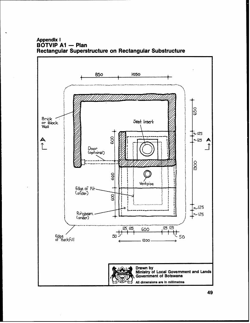
Appendix IBOTVIP Al - PlanRectangular Superstructure on Rectangular Substructure
850 1050
0
or Bbkr-kj ;
n125
9e 7_- -.-Ve pipe
oF9&ackFiid o 2 Pit
Ministry of Local Government and LandsGovernment of BotswanaAll dimensions are In millimetres
49
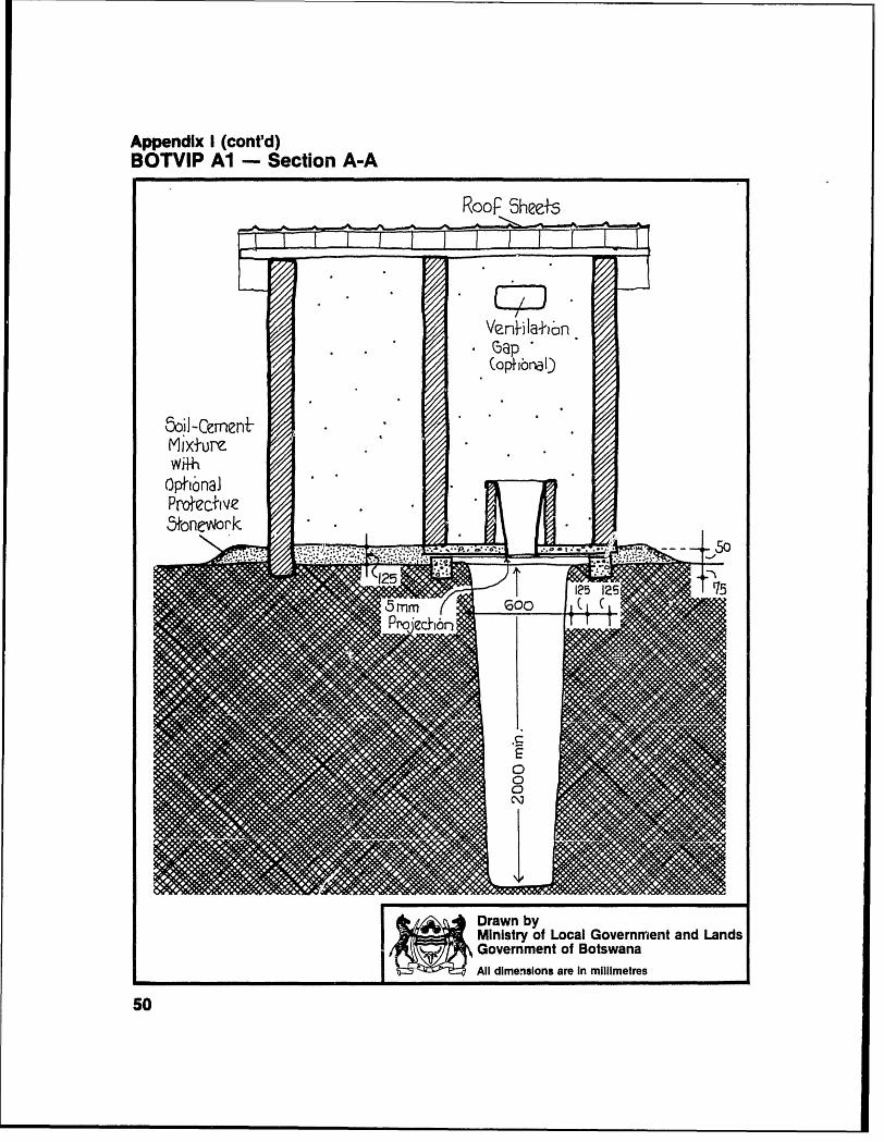
Appendix I (contd)BOTVIP Al -Section A-A
Roof 5heets
Venla +ain
(ophibnal
5oiI-Cemen.Mixture .' * .
Prmtecfive S. 2 .,l l
0 - K inistry of Local Government and Landsi overnment of Botswana
-- | 3 d il dimensions are In mIllmetres
50

Appendix 11BOTVIP A-2 - PlanCircular Superstructure on Rectangular Substructure
Brir-kor Block. ..........
r I
I2 125 ~o..125 32
Dlooo
Governet of Botswana
Al diein are- in'iliete
1551(underD t-jT I
OP Backriii J
+. -- rawn by
Ministry of Local Government and LandsXjiw,Government of Botswana
All dimensions are In millimetres
51

Appendix IIIBOTVIP BI - PlanRectangular 'Superstructure on Circular Substructure
850 IO5o
0S1X
,............................................................
Bnc 5ea ln5r
/.,Ven/p4pe
(optio~nal) 8 0
c BackFill Trape oidajBlockLining
(urder&
* ̂ sDrawn byMinistry of Local Govemment and LandsGovernment of BotswanaAll dimensions are in millimetres
52

Appendix IVBOTVIP B2 - PlanCircular Superstructure on Circular Substructure
,....... ...................
B (opbonaI) So -
Edge 5ea+ lnser' ' .. (8acLFiI *'.,venIpioe
.4oIe
z c - 1200TrapezoidalBlock
~Mlnlstry of Local G;overnment and Lands
Government of Botswana. . 3 QW All dlmenslons are In millimetres
53

Appendix IV (cont'd)BOTVIP B2 -Section B-B
. nJ-il&I-ib
(aphbnaO
, lo - -n e Poje.l
Mlnistry of Local Government and LandsJ , Government of Botswana
xAil dimensions are in millimetres
54

Appendix VCircular Substructure: Trapezoidal-Block Lining
PLAN J
308 308BLOCK
DIMlESIONS 4 Z ;l|150 t 1 ±-t- 125
241) 24J
1542 150150; 900 iImpervious ~ -
BackpiJi --
3 Courses
5ECTIo - - - i ared
First Course l-- :I1orarWed
Drawn byMinistry of Local Government and LandsGovernment of BotswanaAll dimensions are In millimetres
55

Appendix VICircular Substructure: Wire-Mesh-and-Filter-Fabric Lining
PLAN1150PLPAN
5ECTO1N ) 1 112goo) "- 90 125
75
Wlie Mesh - BadcFPilwrapped wi+apprwedPFl+er Fabric . - - -
(Typar or.-- -.E0
c'.J
r- - - oee-Drain
25 31 900 1t2
~% Drawn byMlnistry of Local Govemment and LandsGovernment of BotswanaAll dimensions are In millimetres
56

Appendix VIITypical Rectangular Coversiabs -Types I and 11
Seat Wole(placed cen1rally)
- i4-2o--
-00- - _ _
- ., . . ;R -- . -i; 30
5LAB TYPE I J
8mm &lee] Meshor Rei6Fomirurg Bars Equally 5paced
VentpIpe Hole (placed ceiltrally)
~150)
30
e-.4- -
SLAB TYPEI -30
Drawn byMinistry of Local Government and LandsGovernment of BotswanaAll dimensions are In millimetres
57

Appendix VIl (cont'd)Typical Rectangular Coversiabs -Type Ill
8 n-m3Fee) Mteshor ReinForcin3 Bars5 Equaly5paced
A- A
If-LLH0SLAB TYPE JI30
NOTES'.1. All mesh ends +o have a miniinum cover
oF 3o mmn concrete all around.Z. Concrete +o be mini'murn 20 MiPa.
37.51I- . , - r. -- .- 75-- - --- - -
SECTION A-A 71e5hplaced centrally 30
minim urri
*/1^ 1Drawvn byMinistry of Local Govemment and LandsGovernment of BotswanaAll dimensions are in millimetres
58
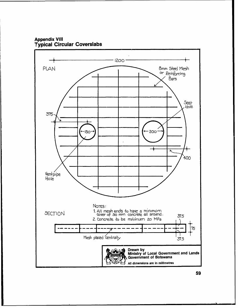
Appendix VilITypical Circular Coversiabs
02000
NOTEs:C1. AllI mesh ende 1o havc a MinnmUm
5CI colver OF~ 30 mm concrete all arouJnd 3752. ConcreAt ±o be m6iinum ao MPa
3 7 5 0 X ( 0 75
Mesh placed\cn~raqy '375
Ministry of Local Government and LandsGovernment of BotswanaAll dimensions are In millimetres
59
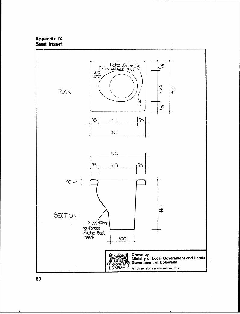
Appendix IXSeat Insert
-Fdxin nocpi ionaj 5e
dfld LoIes4n
PLAN] . Nd
0 05
_ 75 310 75
310 70
elass -F)breReinforcedPlastic Seatlnser-1 1 200
Ministry of Local Government and LandsGovernment of BotswanaAll dimensions are in millimetres
60

Appendix XCement-Wash Hessian Ventpipe
-- R(ysRcreenSewn -o essiar
'. (unnder)
Cemrn4-Wash
- -- Fine Wire Mlesh
0o| liessian- d0| wrappedaround
P LAN
."~'CWV MSh .0 -200 mrri
diameter)
Cement4;
M~orLar .. pushecd 4Ilrough slab
- .9o >overslab2u
Drawn byMinistry of Local Govemment and Lands
< Government of BotswanaAll dimensions are In millimetres
61


![PLTA-0103 Ribbon Blue/Green - conserveland.org · PLTA-0103 Ribbon Blue/Green 3/19/04 3:58 PM Page 1. A Ribbon of Blue,A Ribbon of Green “The Wissahiccon [sic] is of so remark-able](https://static.fdocuments.in/doc/165x107/5d1e780b88c99335368d6d0b/plta-0103-ribbon-bluegreen-plta-0103-ribbon-bluegreen-31904-358-pm-page.jpg)