PLEASE RETAIN THIS MANUAL FOR FUTURE REFERENCE.
38
MODELS: T SERIES These instructions should be read thoroughly before attempting installation. Set up and installation should be performed by qualified installation personnel. Keep area around appliances free and clear from combustibles. PLEASE RETAIN THIS MANUAL FOR FUTURE REFERENCE. THE MONTAGUECOMPANY 1830 STEARMAN AVENUE, P.O. BOX 4954 HAYWARD, CA. 94540-4954 TEL: 510/785-8822 FAX: 510/785-3342 INSTALLATION / OPERATION / SERVICE & PARTS
Transcript of PLEASE RETAIN THIS MANUAL FOR FUTURE REFERENCE.

MODELS:
T SERIES
These instructions should be read thoroughly before attempting installation.
Set up and installation should be performed by qualified installation personnel.
Keep area around appliances free and clear from combustibles.
PLEASE RETAIN THIS MANUAL
FOR FUTURE REFERENCE.
THE MONTAGUECOMPANY
1830 STEARMAN AVENUE, P.O. BOX 4954
HAYWARD, CA. 94540-4954
TEL: 510/785-8822 FAX: 510/785-3342
INSTALLATION / OPERATION / SERVICE & PARTS

IMPORTANT FOR YOUR SAFETY
THIS MANUAL HAS BEEN PREPARED FOR PERSONNEL QUALIFIED TO INSTALL
GAS EQUIPMENT, WHO SHOULD PERFORM THE INITIAL FIELD START-UP AND
ADJUSTMENTS OF THE EQUIPMENT COVERED BY THIS MANUAL.
POST IN A PROMINENT LOCATION THE INSTRUCTIONS TO BE FOLLOWED
IN THE EVENT THE SMELL OF GAS IS DETECTED. THIS INFORMATION CAN BE
OBTAINED FROM THE LOCAL GAS SUPPLIER.
WARNING
IN THE EVENT A GAS ODOR IS DETECTED, SHUT DOWN
UNITS AT MAIN SHUTOFF VALVE AND CONTACT THE
LOCAL GAS COMPANY OR GAS SUPPLIER FOR SERVICE.
FOR YOUR SAFETY
DO NOT STORE OR USE GASOLINE OR OTHER
FLAMMABLE VAPORS OR LIQUIDS IN THE VICINITY OF
THIS OR ANY OTHER APPLIANCE.
WARNING
IMPROPER INSTALLATION, ADJUSTMENT, ALTERATION, SERVICE OR
MAINTENANCE CAN CAUSE PROPERTY DAMAGE, INJURY, OR DEATH.
READ THE INSTALLATION, OPERATING, AND MAINTENANCE INSTRUCTIONS
THOROUGHLY BEFORE OPERATING THIS EQUIPMENT.
SAVE THESE INSTRUCTIONS FOR FUTURE USE.

IMPORTANT
SHIPPING DAMAGE CLAIM PROCEDURE:
For your protection, please note that equipment in this shipment was carefully
inspected and packed by skilled personnel before leaving the factory. The
transportation company assumed full responsibility for safe delivery upon acceptance
of this shipment.
IF SHIPMENT ARRIVES DAMAGED:
1. VISIBLE LOSS OR DAMAGE—Be certain this is noted on freight bill or express
receipt, and signed by person making delivery.
2. FILE CLAIM FOR DAMAGES IMMEDIATELY—Regardless of the extent of
damage.
3. CONCEALED LOSS OR DAMAGE—If damage is unnoticed until merchandise is
unpacked, notify transportation company or carrier immediately, and file
―concealed damage‖ claim with them. This should be done within fifteen (15) days
of date that delivery was made to you. Be sure to retain container for inspection.
We cannot assume responsibility for damage incurred in transit. We will, however, be glad to furnish you with necessary
documents to support your claim.

INSTALLATION
The Montague Technostar gas ranges are manufactured for use with the type of gas indicated on
the nameplate.
The Montague Technostar gas convection oven type ranges are produced with the best possible
material and workmanship. PROPER INSTALLATION IS ESSENTIAL FOR SAFE AND EFFICIENT
TROUBLE– FREE OPERATION.
THE INSTALLATION INSTRUCTIONS CONTAINED HEREIN ARE FOR
THE USE OF QUALIFIED INSTALLATION AND SERVICE PERSONNEL
ONLY. INSTALLATION OR SERVICE BY OTHER THAN QUALIFIED
PERSONNEL MAY RESULT IN DAMAGE TO THE OVEN AND/OR
INJURY TO THE OPERATOR.
Qualified installation personnel are individuals, a firm, corporation or company which either in
person, or through a representative are engaged in, and are responsible for:
A. The installation or replacement of gas piping or the connection, installation, repair or servicing
of equipment, who is experienced in such work, familiar with all precautions required, and has
complied with all requirements of state or local authorities having jurisdiction. Reference: National
Fuel Gas Code Z223.1, Section 1.4.
B. The installation of electrical wiring from the electric meter, main control box or service outlet to
the electric appliance. Qualified installation personnel must be experienced in such work, be familiar
with all precautions required and have complied with all requirements of state and local authorities
having jurisdiction. Reference: National Electric Code, NFPA No. 70.
READ CAREFULLY AND FOLLOW THESE INSTRUCTIONS
THE RANGE(S) MUST BE INSTALLED IN ACCORDANCE WITH LOCAL CODES,
OR IN THE ABSENCE OF LOCAL CODES, WITH THE NATIONAL FUEL GAS
CODE, ANSI Z223.1, NATURAL GAS INSTALLATION CODE, CAN/CGA-B149.1,
OR THE PROPANE INSTALLATION CODE CAN/CGA-B149.2, AS APPLICABLE,
INCLUDING:
1. The appliance and its individual shutoff valve must be disconnected from the gas supply piping
system during any pressure testing of that system at test pressures in excess of 1/2 psig.
(3.45 kPa).
2. The appliance must be isolated from the gas supply piping system by closing its individual
manual shutoff valve during any pressure testing of the gas supply piping system at test
pressure equal to or less than 1/2 psig. (3.45 kPa).

INSTALLATION
THE UNIT, WHEN INSTALLED, MUST BE ELECTRICALLY GROUNDED IN
ACCORDANCE WITH LOCAL CODES, OR IN ABSENCE OF LOCAL CODES,
WITH THE NATIONAL ELECTRICAL CODE, ANSI/NFPA 70, OR THE CANADIAN
ELECTRICAL CODE, CSA C22.2, AS APPLICABLE.
PROVISIONS MUST BE MADE FOR ADEQUATE AIR SUPPLY TO THE UNIT.
Ventilating Hood
The range(s) must be installed under a properly designed hood. The hood should extend at least 6‖
beyond all sides of the unit. The hood should be connected to an adequate mechanical exhaust
system.
Information on the construction and installation of ventilating hoods may be obtained from the
―Standard for the Installation of Equipment for the Removal of Smoke and Grease Laden Vapors
from Commercial Cooking Equipment‖, NFPA 96, available from the National Fire Protection
Association. Batterymarch Park, Quincy, Ma 02269.
It is also necessary that sufficient room air ingress be allowed to compensate for the amount of air
removed by the ventilating system. Otherwise, a subnormal atmospheric pressure will occur which
may interfere with burner performance or may extinguish the pilot flame. In case of unsatisfactory
range performance, check with the exhaust fan in the ―OFF‖ position.
CLEARANCES
Adequate clearance must be provided at the side, back and in the aisle to allow the doors to open
sufficiently to permit the removal of the racks and for serviceability. Adequate clearance for air
openings into the combustion chamber must be provided.
COMBUSTIBLE NONCOMBUSTIBLE
CONSTRUCTION CONSTRUCTION
BACK: 2” (5.1 cm) 2” (5.1 cm)
LT & RT SIDE: 11” (27.9 cm) 2” (5.1 cm)
6” (15.2 cm) HIGH LEGS: SUITABLE FOR INSTALLATION ON COMBUSTIBLE FLOORS. WITHOUT LEGS: FOR USE ONLY ON NON-COMBUSTIBLE FLOORS.
CAUTION
DO NOT OBSTRUCT THE FLOW OF COMBUSTION AND VENTILATION AIR.
KEEP APPLIANCE AREA FREE AND CLEAR FROM COMBUSTIBLES.

TABLE OF CONTENTS INSTALLATION
ASSEMBLY . . . . . . . . . . . . . . . . . . . . . . . . . . . . . . . .1
LEGS . . . . . . . . . . . . . . . . . . . . . . . . . . . . . . . . . . 1
DOOR HANDLE . . . . . . . . . . . . . . . . . . . . . . . . . 1
HIGH SHELF . . . . . . . . . . . . . . . . . . . . . . . . . . . . 1
OPEN TOP GRATE . . . . . . . . . . . . . . . . . . . . . . . 2
ADJUSTMENTS . . . . . . . . . . . . . . . . . . . . . . . . . . . . 2
LEGS . . . . . . . . . . . . . . . . . . . . . . . . . . . . . . . . . . 2
CURB MOUNT . . . . . . . . . . . . . . . . . . . . . . . . . . 2
FRY TOP . . . . . . . . . . . . . . . . . . . . . . . . . . . . . . . 3
PRESSURE REGULATOR . . . . . . . . . . . . . . . . . 3
GAS CONNECTIONS . . . . . . . . . . . . . . . . . . . . . . . 3
GAS LINE . . . . . . . . . . . . . . . . . . . . . . . . . . . . . . 4
PILOT ADJUSTMENT . . . . . . . . . . . . . . . . . . . . . 5
BURNER ADJUSTMENT . . . . . . . . . . . . . . . . . . .6
OPERATION
GAS CONTROLS . . . . . . . . . . . . . . . . . . . . . . . . . . . 7
MANUAL & FLAME FAILURE VALVES . . . . . . . 7
(OPEN TOP, HOT TOP, & FRYTOP)
THERMOSTATIC CONTROLLED FRYTOP . . . . . . 8
LIGHTING OVEN PILOT (T60 & VT60) . . . . . . . . . .8
LIGHTING OVEN PILOT (T26 & VT26) . . . . . . . . . .9
OVEN OPERATION . . . . . . . . . . . . . . . . . . . . . . . .10
MAINTENANCE
CARE & CLEANING . . . . . . . . . . . . . . . . . . . . . . . .11
EXTERIOR , OPEN TOP . . . . . . . . . . . . . . . . . .11
FRYTOP, HOT TOP, & OVEN INTERIOR . . . . .12
SERVICE
PARTS . . . . . . . . . . . . . . . . . . . . . . . . . . . . . . . . . . 13
PILOT SAFETY, PIEZO IGNITOR . . . . . . . . . . 13
OVEN PILOT BURNER ASSY . . . . . . . . . . . . . . 14
FRYTOP T-STAT INSTALLATION . . . . . . . . . . .15
FRYTOP BYPASS ADJUSTMENT . . . . . . . . . . .16
FRYTOP CALIBRATION . . . . . . . . . . . . . . . . . . .17
OVEN THERMOSTAT (T60 & VT60) . . . . . . . . . 17
OVEN BYPASS ADJUSTMENT (T60 & VT60) . .18
OVEN THERMOSTAT (T26 & VT26) . . . . . . . . . 19
OVEN BYPASS ADJUSTMENT (T26 & VT26) . .19
OVEN T-STAT CALIBRATION (T26 & VT26) . . .20
OPERATIONAL DIFFICULTIES . . . . . . . . . . . . . . . 21
OVEN PILOT, OVEN BURNER, OVEN TEMP . . 21
EXPLODED VIEWS T26 OPEN TOP OPTION . . . . . . . . . . . . . . . . . . . .22 T26 OVEN . . . . . . . . . . . . . . . . . . . . . . . . . . . . . . . 23 T60 OPEN TOP OPTION . . . . . . . . . . . . . . . . . . . 24 T60 OVEN . . . . . . . . . . . . . . . . . . . . . . . . . . . . . . . 25 VT SERIES . . . . . . . . . . . . . . . . . . . . . . . . . . . . . . 26 V & VT FRYTOP OPTION . . . . . . . . . . . . . . . . . . .27
INSTALLATION
ASSEMBLY
Uncrate range as near to final location as possible. Remove all shipping wire from burners and all
packing material and accessories from oven interior.
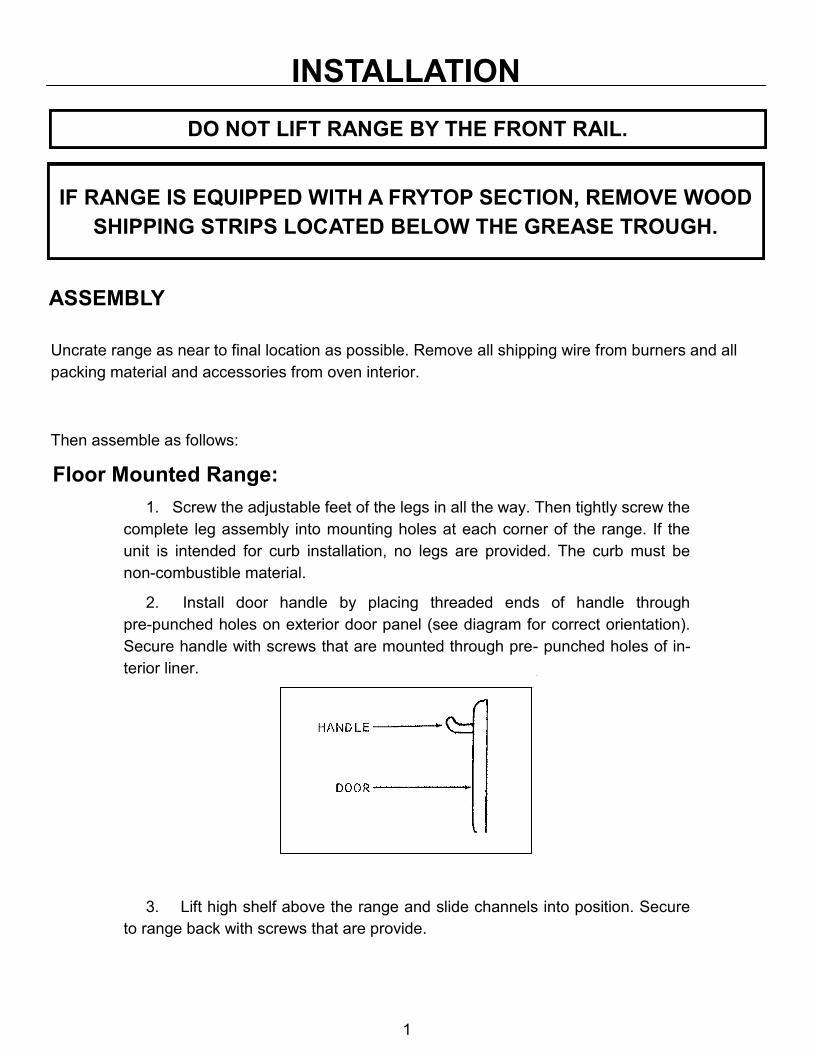
DO NOT LIFT RANGE BY THE FRONT RAIL.
IF RANGE IS EQUIPPED WITH A FRYTOP SECTION, REMOVE WOOD
SHIPPING STRIPS LOCATED BELOW THE GREASE TROUGH.
Then assemble as follows:
Floor Mounted Range:
1. Screw the adjustable feet of the legs in all the way. Then tightly screw the
complete leg assembly into mounting holes at each corner of the range. If the
unit is intended for curb installation, no legs are provided. The curb must be
non-combustible material.
2. Install door handle by placing threaded ends of handle through
pre-punched holes on exterior door panel (see diagram for correct orientation).
Secure handle with screws that are mounted through pre- punched holes of in-
terior liner.
3. Lift high shelf above the range and slide channels into position. Secure
to range back with screws that are provide.
1

INSTALLATION
Counter Ranges:
Set unit in desired position and secure to counter using holes provided at rear and bracket at front.
All Ranges:
1. Install Open Top sections by aligning cut-outs of open top grate ( A )
with pattern of the burner head ( B ). Grate should have even spacing around
the body of the burner head ( C ).
2. Install top burner valve handles and thermostat knob(s). If top burner
valve handles fit loose on valve shaft, spread slot on end of shaft slightly with
screwdriver blade so that handle will fit snug.
3. When range is in permanent position, level unit by placing carpenter’s
level on oven bottom and level from front to back and side to side.
ADJUST AS FOLLOWS:
FLOOR & COUNTER INSTALLATION ON LEGS: The foot of the leg
should be adjusted all the way in before attempting to level the unit. To increase
the height of the leg, rotate the adjustable foot clockwise until desired height is
achieved. Repeat this procedure with all legs. Use a level to ensure that all legs
have been adjusted correctly.
CURB INSTALLATION: Level range from front to rear and side to side us-
ing a carpenter’s level. Place shim under low side.
(A) (B) (C)
2

INSTALLATION
FRY TOP RANGES:
Leveling bolts are at the rear of the range under the Fry Top
plate. Adjust leveling bolts so that the plate is pitched to the
front to provide for grease runoff and proper ventilation. The
heat from the plate should rise to the rear of the unit to
prevent damage to valves and other components. Be sure
wooden strips have been removed from below grease trough.
GAS PRESSURE REGULATOR
THIS RANGE IS DESIGNED FOR USE WITH A GAS PRESSURE REGULATOR.
THE REGULATOR SUPPLIED WITH THIS UNIT MUST BE USED.
FOR NATURAL GAS: This gas pressure regulator is factory adjusted for 6.0‖ W.C. manifold
pressure. The rated inlet pressure to the regulator should be 8 to 14 W.C.‖
FOR PROPANE GAS: This gas pressure regulator is factory adjusted for 10.0‖ W.C.
manifold pressure. The rated inlet pressure to the regulator should be 12 to 14‖ W.C.
Unless otherwise specified, the range is equipped with fixed orifices for use
with a manifold pressure of 6.0” water column for natural gas and 10.0” water
column for propane gas.
GAS CONNECTION:
Before connecting the range to the gas supply line, be sure that all new piping has been cleaned
and purged to prevent any foreign matter from being carried into the controls by the gas. In some
cases, filters or drops are recommended. A separate Gas Shut Off Valve must be installed upstream
from the gas pressure regulator adjacent to the range and be located in an accessible area.
It is important that adequately sized piping be run directly to the point of connection at the
range, with as few elbows and tees as possible. Consult local gas company for proper piping size
and gas pressure.
3

INSTALLATION
PIPE JOINT COMPOUND OR THREAD SEALANT THAT IS USED SHOULD BE
RESISTANT TO ACTION OF LIQUIFIED PETROLEUM GASES.
Install the gas pressure regulator with gas flowing as indicated by the arrow on the regulator. Use
pipe compound or thread sealant and carefully thread regulator to pipe so that there is no cross
threading, etc., which could cause leakage.
Apply wrench only to the flat areas around the pipe tapping at the end being threaded to the pipe
to avoid possible damage to the regulator body which could result in leakage.
Connect the gas supply line from the Service Gas Shut Off valve to the inlet side of the gas
pressure regulator using 3/4‖ pipe. If flexible or semi-flexible connectors are used, an AGA listed
flexible connector with a minimum I.D. equal to 3/4‖ pipe must be used. Line sizing should be based
on the BTU rating or requirement of the unit installed. DO NOT USE A DOMESTIC APPLIANCE
TYPE GAS FLEXIBLE CONNECTOR. Avoid kinks or sharp bends that could restrict gas flow.
Turn Gas Shut Off Valve ―ON‖ and immediately check carefully for gas leaks. Do this before
attempting to operate the range.
TEST ALL PIPE JOINTS FOR LEAKS BEFORE OPERATING RANGE.
THIS INCLUDES ALL GAS CONNECTIONS THAT MAY HAVE LOOSENED DURING
SHIPMENT. USE A RICH SOAP SOLUTION (OR OTHER ACCEPTED LEAK
TESTER) AROUND ALL PIPE CONNECTIONS AND ALL OTHER JOINTS.
DO NOT USE AN OPEN FLAME. ABSOLUTELY NO LEAKAGE SHOULD OCCUR,
OTHERWISE THERE IS A DANGER OF FIRE OR EXPLOSION DEPENDING UPON
CONDITIONS. NEVER USE IF LEAKAGE IS DETECTED.
4

INSTALLATON
PILOT ADJUSTMENT - TOP BURNERS (STANDARD MANUAL VALVE)
OPEN TOP: Pilots are factory set. No adjustment is necessary.
FRY TOP AND HOT TOP: Each pilot is controlled by a pilot valve. Turn adjusting screw
until pilot flame is 1/2‖ high.
PILOT VALVE
PILOT ADJUSTMENT - TOP BURNERS (FLAME FAILURE VALVE)
OPEN TOP: Pilots are factory adjusted. DO NOT ADJUST.
FRYTOP AND HOT TOP: Pilots are factory adjusted. DO NOT ADJUST.
DO NOT ADJUST
5

INSTALLATION
BURNER ADJUSTMENT:
The efficiency of the range depends on a delicate balance between the supply of air and the
volume of gas so that complete combustion is achieved. Whenever this balance is disturbed, poor
operating characteristics occur.
The air supply is controlled by an air shutter on the front of the burner. The air shutter openings
should be increased until the flame on the burner begins to ―lift‖. The air shutter should then be
closed slightly and locked in place. A yellow streaming flame indicates insufficient air. This condition
can be corrected by increasing the air shutter opening
. ADJUSTMENT
SCREW
FRY TOP AND OVEN THERMOSTATS:
The by-pass (minimum burner flame) has been adjusted at the factory and should require no
further adjustment.
THE BY-PASS FLAME MUST BE RECHECKED WHEN PERFORMING
CHECKOUT OF RANGE PRIOR TO PLACING EQUIPMENT IN
SERVICE. THE BY-PASS MUST BE SET CAREFULLY AND
ACCURATELY. REFER TO SERVICE SECTION OF THIS MANUAL FOR
PROPER PROCEDURE.
MODELS T26 & VT 26 GRIDDLES
MODELS T60 & VT 60 GRIDDLES MODELS T26 & VT 26 OVEN
BYPASS BYPASS
6

OPERATION
OPERATIONG INFORMATION FOR THE RANGE HAS BEEN
PREPARED FOR USE BY QUALIFIED AND/OR PROFESSIONAL
OPERATING PERSONNEL
CAUTION
DO NOT OBSTRUCT THE FLOW OF COMBUSTION AND
VENTILATION AIR. KEEP THE APPLIANCE AREA FREE AND CLEAR
FROM COMBUSTIBLES
IN THE EVENT A GAS ODOR IS DETECTED, SHUT DOWN UNITS AT
MAIN SHUT OFF VALVE AND CONTACT THE LOCAL GAS COMPANY
OR GAS SUPPLIER FOR SERVICE.
GAS CONTROLS (STANDARD MANUAL VALVE):
TOP BURNERS - Open Top, Hot Top, and Manual Fry Top
Check that pilots are burning. Then rotate valve handles counterclockwise to full on, burner will
ignite automatically. Adjust flame height as desired. To shut down, rotate valve handle clockwise to
the ―OFF‖ position.
GAS CONTROLS (FLAME FAILURE VALVE):
TOP BURNERS - Open Top, Hot Top, Fry Top
1. Push in the tap and turn it counter-clockwise to the ignition position
2. Holding the tap in fully in, light the pilot with a match or extended lighter.
3. When the pilot is lit, continue to hold the tap fully in for 20 seconds, then release it. If the pilot
goes out, wait for (5) minutes, then repeat from step 1.
4. When the pilot is established, push the tap in again and turn it counter-clockwise to the full flame
position‖ ― , thus lighting the main burner.
5. For low flame or simmer, push tap in and turn it counter-clockwise to the lowest position.
6. To shut burner off, turn the dial to the position and the safety device will disengage within
60 seconds.
7

OPERATION
GAS CONTROLS (THERMOSTAT CONTROLLED)
TOP BURNERS - Fry Top
Check that pilot(s) are burning. Then push thermostat dial inward and rotate dial counter-clockwise
to maximum thermostat setting, burner(s) will ignite automatically. After ignition turn thermostat dial
to desired setting. To shut down, rotate thermostat dial clockwise to ― OFF ― position.
OVEN
A.) T60 & VT60 SERIES (LIGHTING)
PILOT SAFETY
PILOT
WINDOW
PIEZO IGNITER
1. Turn thermostat knob to ― OFF ― position and wait five (5) minutes.
2. Remove burner compartment cover and open pilot access door.
3. Locate the Piezo Igniter in front of the pilot access door..
4. Press and hold in the red button of the Pilot Safety Valve while repeatedly depressing the button
on the Piezo Igniter until the pilot burner ignites.
5. After pilot burner ignites, continue to hold Pilot Safety red button depressed for 30 to 45 seconds
or until pilot holds when button is released. If pilot goes out, repeat process.
6. If the pilot burner is unable to be lit with the piezo igniter, apply a lighted match or extended
lighter to the pilot burner.
7. Close pilot access door and replace burner access panel.
8. Push thermostat dial inward and rotate dial counter-clockwise to desired temperature setting.
9. IN THE EVENT OF PILOT FAILURE, ROTATE THERMOSTAT DIAL CLOCKWISE TO “ OFF “
POSITION AND WAIT FIVE (5) MINUTES FOR UNBURNED GAS TO ESCAPE FROM
RANGE.
8

OPERATION
OVEN
B.) V26 & VT26 SERIES (LIGHTING)
THERMOSTAT
PILOT
SAFETY
MAIN BURNER VALVE
PIEZO IGNITER
1. Turn Main Burner Valve to ― OFF ― position.
2. Remove burner compartment cover and open pilot access door.
3. Locate Piezo Igniter , mounted under the Main Burner Valve on the oven Control Panel.
4. Press and hold in the red button of the Pilot Safety Valve while repeatedly depressing the button
on the Piezo Igniter until the pilot burner ignites.
5. After pilot burner ignites , continue to hold Pilot Safety red button depressed for 30 to 45 seconds
or until pilot holds when button is released. If pilot goes out, repeat process.
6. If the pilot burner is unable to be lit with the Piezo Igniter, apply a lighted match or extended
lighter to the pilot burner
7. Close pilot access door and replace burner access panel.
8. Set desired temperature on thermostat then turn Main Burner Valve fully open to the ― ON ―
position.
9. IN THE EVENT OF PILOT FAILURE, ROTATE MAIN BURNER VALVE CLOCKWISE TO THE
“ OFF “ POSITION AND WAIT (5) MINUTES FOR UNBURNED GAS TO ESCAPE FROM
RANGE.
9

OPERATION
C.) SHUT DOWN
Rotate thermostat dial clockwise to ― OFF ― position. (T60 &VT60)
Rotate Main Burner Valve clockwise to the ― OFF ― position. (T26 & VT26)
OVEN OPERATION
1. Turn thermostat dial to desired temperature.
2. Limit pre-heat time to 10-20 minutes.
3. Place food in oven. Make sure pans do not touch each other, or the oven walls.
4. Do not cover racks with aluminum foil.
5. Load and unload quickly. Avoid frequent opening of doors.
6. Turn off when not in use.
SUGGESTIONS
There is not need to preheat an Open Top burner. Use full flame to start foods cooking quickly;
reduce the flame to simmer foods. Regulate the burner so that flame tips just touch the bottom
of the utensil. Use lids on pots to keep heat in. Turn burner off when not in use.
Preheat Fry Top 10-15 minutes prior to use. Usually, medium to low flame is adequate for light
frying. If Fry Top has a thermostat, use it to avoid wasting gas and for best results. During slack
periods, turn the burner down.
10

MAINTENANCE
CARE AND CLEANING:
The complete range should be given a periodic general cleaning. Lint and grease suspended in
the air tend to collect in air passages. Therefore, all flueways, air passages and openings, burner
ports, primary air openings, etc., should be periodically cleaned to prevent clogging.
EXTERIOR:
STAINLESS STEEL SURFACE: To remove normal dirt, grease, or product residue from
stainless steel, use ordinary soap and water (with or without detergent) applied with a sponge or
cloth. Dry thoroughly with a clean cloth.
To remove grease and food splatter, or condensed vapors that have baked on the equipment,
apply cleanser to a damp cloth or sponge and rub cleanser on the metal in the direction of the
polished lines on the metal. Rubbing cleanser as gently as possible in the direction of the polished
lines will not mar the finish of the stainless steel. NEVER RUB WITH A CIRCULAR MOTION. Soil
and burned deposits which do not respond to the above procedure can usually be removed by
rubbing the surface with SCOTCH-BRITE scouring pads or STAINLESS scouring pads. DO NOT
USE ORDINARY STEEL WOOL as any particles left on the surface will rust and further spoil the
appearance of the finish. NEVER USE A WIRE BRUSH, STEEL SCOURING PADS (EXCEPT
STAINLESS), SCRAPER, FILE OR OTHER STEEL TOOLS. Surfaces which are marred collect dirt
more rapidly and become more difficult to clean. Marring also increases the possibility of corrosive
attack.
TO REMOVE HEAT TINT: Darkened areas sometimes appear on stainless steel surfaces
where the area has been subjected to excessive heat. These darkened areas are caused by
thickening of the protective surface of the stainless steel and are not harmful. Heat tint can normally
be removed by the foregoing, but tint which does not respond to this procedure calls for a vigorous
scouring in the direction of the polish lines, using SCOTCH-BRITE scouring pads or a STAINLESS
scouring pad in combination with a powdered cleanser. Heat tint action may be lessened by not
applying or by reducing heat to equipment during slack periods.
OPEN TOP SECTION:
DAILY: After grates are cooled, soak in solution of sal soda or other grease solvent.
Thoroughly wash open top section with a damp cloth using a mild detergent soap. Rinse with clean,
damp cloth and dry thoroughly. Remove and clean drip tray(s) under burners.
11

MAINTENANCE
WEEKLY: Brush burner head with a stiff wire brush and clean clogged ports with a stiff wire
or ice pick.
Excessive grease build up may be removed from burners by soaking in a solution of washing
soda or any good grease solvent. Dry burners by inverting on oven rack in a low temperature oven.
FRY TOP SECTION:
DAILY: Use flat edge of spatula or metal scraper to keep surface free of encrusted material
during use, wipe frequently with heavy absorbent cloth. After griddle is cooled, polish with soft
griddle stone or a good grade grill pad. DO NOT SCRATCH. The griddle may be washed with warm
water and a cleanser. Water will not crack this griddle plate.
Empty grease container as often as necessary.
To oil the griddle, use a hydrogenated shortening. Never use salad oils, margarine or butter, as
these shortenings cannot withstand temperatures greater than 300 degrees Fahrenheit.
HOT TOP SECTION:
DAILY: Wipe top with heavy burlap or steel wool. Rub briskly until clean. The Hot Top plate
may be washed with warm water and a cleanser. Water will not crack this Hot Top Plate.
OVEN INTERIOR:
Aluminum Steel - Top, Sides, and Back:
Porcelain Enamel - Bottom and Door Liner:
Wipe up spillovers while oven is hot. Wait until oven is cool for complete cleaning. Spray type
oven cleansers may be used. A mild abrasive nylon cleaning pad can be used for stubborn
spillovers or stains After cleaning, rinse well with 1/4 cup of vinegar to 1 quart water solution to
neutralize any caustic residue of cleaning compound. Wipe dry.
CAUTION
Do not use wire brushes, steel wool or caustic solutions such as spray type cleansers, ammonia,
lye or soda ash. Damage to the aluminum coating will result. USE ONLY CLEANERS THAT ARE
RECOMMENDED FOR USE ON ALUMINUM.
12

SERVICE
WHEN SERVICE IS NEEDED, CONTACT A LOCAL SERVICE COMPANY,
DEALER, OR FACTORY TO PERFORM MECHANICAL MAINTENANCE AND
REPAIRS. THESE INSTRUCTIONS ARE INTENDED FOR USE BY COMPETENT
SERVICE PERSONNEL.
CAUTION
DISCONNECT POWER BEFORE DOING ANY SERVICE WORK. EACH SECTION
HAS SEPARATE ELECTRICAL SUPPLY CONNECTION. TURN OFF GAS
SUPPLY WHEN SERVICING GAS CONTROL SYSTEM.
PILOT SAFETY VALVE
The Baso Pilot Safety is an automatic 100% safety pilot which
provides complete gas shut off in event of pilot failure. The safety
valve is held closed by spring pressure. When red button is
pushed by hand, gas flows to pilot. Pilot heats thermocouple
creating a very small amount of electricity. This energizes a
magnetic coil under the red button and holds the valve open,
permitting gas to flow to main burner and pilot without holding
pressure on red button. In the event of pilot failure, the flow of
electricity will stop and spring will stop flow of gas to both pilot and
oven burner.
PIEZO IGNITER
The PIEZO IGNITER creates an ignition spark at the pilot burner
when the red button is depressed until it clicks. The spark is gen-
erated at the tip of the OVEN ELECTRODE, which is positioned
inside of the pilot burner hood. The spark jumps from the OVEN
ELECTRODE to the pilot burner hood, across the pilot gas exit.
13

SERVICE
OVEN PILOT BURNER:
Pilot Service In The Event Of Pilot Failure:
1. If pilot flame burns yellow, clean pilot orifice and pilot burner to insure a steady blue flame. The
orifice can be cleaned by washing in a solvent and/or blowing out with air.
2. Flame must surround the thermocouple tip for approximately 1/2 Inch.
3. Thermocouple lead connections must be tight, clean and free of grease. The thermocouple nut
should be started and turned all the way by hand. An additional quarter turn with a small wrench
will then be sufficient.
4. Correct gas pressure is critical for maintaining proper pilot flame size.
CAUTION
OVERTIGHTENING MAY CAUSE DAMAGE TO THE THERMOCOUPLE OR
MAGNET AND IS UNNECESSARY SINCE THIS IS AN ELECTRIC CONNECTION.
DO NOT GRASP HEAD WITH TOOLS WHILE CHANGING COMPONENT.
PILOT BURNER
(T26 & T16)
(NATURAL) P/N 50916-7
(PROP) P/N 52327-5
(T60)
(NATURAL) P/N 23218-1
(PROP) P/N 34506-7
THERMOCOUPLE
P/N 1013-8
ELECTRODE W/ LEAD
P/N 26871-2
THERMOCOUPLE OUTPUT
OPEN CIRCUIT MILLIVOLT RANGE
NORMAL NOT LESS THAN
15-25 8
If the closed circuit check shows thermocouple output is greater than 8 millivolts and pilot will
not remain lit when reset button is released, replace pilot safety valve.
14
SERVICE
FRYTOP THERMOSTAT: (T26 & VT26) & (T60 & VT60)
The model BJ Robertshaw is a combination thermostat and gas valve. The gas is turned on and
the temperature setting made by a single rotation of the dial. This valve automatically locks itself in
the ― OFF ― position. To use, push dial inward, rotate counter-clockwise to the desired temperature.
To shut gas off, rotate clockwise to the ― OFF ― position.
This thermostat is a precision instrument carefully made and properly calibrated (i.e. the dial is
properly set) at the factory to control temperatures accurately. It should control temperatures for the
proper cooking of food without recalibration. The calibration of the thermostat should not be changed
until considerable experience with cooking results have definitely proved that the thermostat is not
maintaining the proper temperature.
CAUTION
THE RECALIBRATION SHOULD NOT BE MADE UNTIL THE BYPASS
( MINIMUM BURNER) FLAME HAS BEEN PROPERLY ADJUSTED.
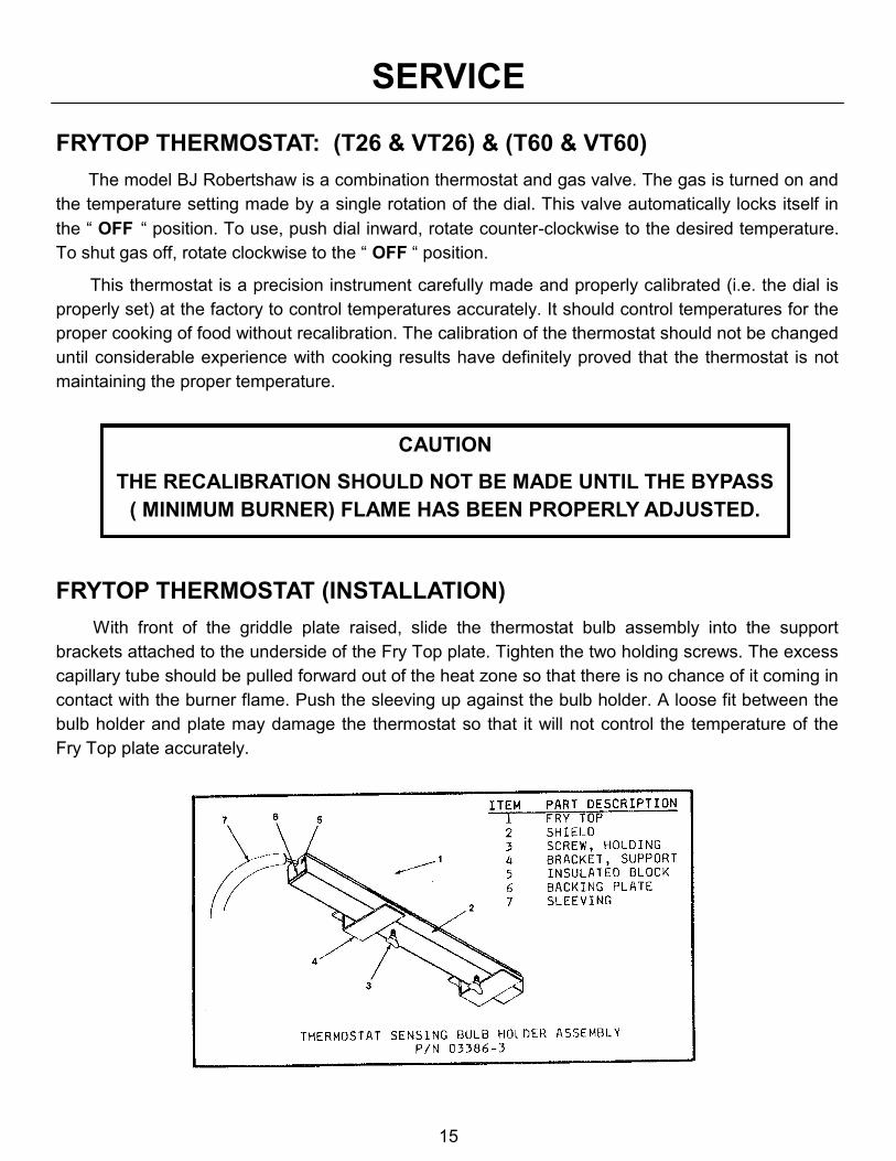
FRYTOP THERMOSTAT (INSTALLATION)
With front of the griddle plate raised, slide the thermostat bulb assembly into the support
brackets attached to the underside of the Fry Top plate. Tighten the two holding screws. The excess
capillary tube should be pulled forward out of the heat zone so that there is no chance of it coming in
contact with the burner flame. Push the sleeving up against the bulb holder. A loose fit between the
bulb holder and plate may damage the thermostat so that it will not control the temperature of the
Fry Top plate accurately.
15

SERVICE
ADJUSTMENT OF BYPASS (MINIMUM BURNER) FLAME:
(T26 & VT26) & (T60 & VT60)
This is the flame which must be maintained on the burners when the Fry Top has reached the
temperature set on the dial. Enough gas must be bypassed by the control to keep the entire burner
lit. The thermostat regulates the flame from high to low in accordance with the Fry Top temperature
and will automatically turn down to this bypass flame when the temperature set on dial is attained.
Special care should be taken to see that the thermostat bulb is in its proper place and no part of
the capillary tube is in any flame or heat zone. The Fry Top plate should never be removed without
first removing the thermostat bulb(s) from beneath the plate. Never allow capillary tube to be kinked
or crushed.
THE BYPASS MUST BE SET CAREFULLY AND ACCURATELY AS FOLLOWS:
1. Light burners and turn Dial (A) counter-clockwise and to a point midway between the ―GAS ON‖
mark and the next graduation to the right of it (shown by ―X‖). If the burner goes out entirely, the
bypass is closed.
2. Slip off Dial (A). Remove the valve panel from the front of the range.
3. With a screwdriver, turn bypass adjustor (B). Turning it out counter-clockwise increases the
bypass flame; turning it in clockwise decreases the bypass flame. Adjust until there is a flame
approximately 1/8‖ high over the entire burner.
4. Replace dial, rotating dial clockwise until it snaps into its original position.
5. Reinstall the valve panel on front of the range.
16

SERVICE
FRY TOP THERMOSTAT CALIBRATION CHECK:
The Fry Top temperature should be checked or recalibrated with the Fry Top hot. NOTE: See
―Adjustment of Bypass (Minimum Burner) Flame‖ before recalibrating this thermostat.
HOT CHECK METHOD:
1. Place reliable thermometer in center of the top of the Fry Top over the thermal bulb.
2. Set dial (A) to 350 degrees F.
3. Wait until temperature rises and remains constant.
4. If dial does not agree with thermometer readings, slip off dial (A) and push out metal insert.
5. Replace dial, turn to 350 degree F mark.
6. Hold dial firmly, insert screwdriver through center of dial and push calibration stem © inward. DO
NOT TURN THIS STEM.
7. While holding calibration stem © in firmly with screwdriver, turn dial until it is set at the actual Fry
Top temperature as it is shown by the thermometer. Release pressure on calibration stem. Re-
place dial insert.
OVEN THERMOSTAT: (T60 & VT60)
The T60 & VT 60 model ovens are controlled with the BJ Invensys Thermostat. This is a
combination thermostat and gas valve. The gas is turned on and the temperature setting is made by
a single rotation of the dial. This valve automatically locks itself in the ― OFF ― position. To use,
push dial inward, rotate counter-clockwise to the desired temperature. To shut gas off, rotate
clockwise to ― OFF ― position.
This thermostat is a precision instrument carefully made and properly calibrated (i.e. the dial is
properly set) at the factory to control temperatures accurately. It should control temperatures for the
proper cooking of food without recalibration. The calibration of this thermostat should not be
changed until considerable experience with cooking results has definitely proved that the thermostat
is not maintaining the proper temperature.
CAUTION
THE RECALIBRATION SHOULD NOT BE MADE UNTIL THE BYPASS
(MINIMUM BURNER) FLAME HAS BEEN PROPERLY ADJUSTED.
17

SERVICE
ADJUSTMENT OF BYPASS (MINIMUM BURNER) FLAME:
(T60 & VT60)
This is the flame that must be maintained on the burners when the oven has come up to the
temperature set on the dial. Enough gas must be bypassed by the control to keep the entire burner
lit. The thermostat regulates the flame from high to low in accordance with the oven temperature and
will automatically turn down to this bypass flame when the temperatures set on the dial is attained in
the oven.
THE BYPASS MUST BE SET CAREFULLY AND ACCURATELY AS
FOLLOWS :
1. Light burners and turn dial ( A ) counter-clockwise and to a point midway between the ― Gas On ―
mark and next graduation to the right of it ( shown by ― X ― ). If the burner goes out entirely, the
bypass is closed.
2. Slip off dial ( A ). Remove valve panel from front of range.
3. With a screw driver, turn Bypass adjuster ( B ). Turning it out counter-clockwise increases the
bypass flame; turning it in clockwise decreases the bypass flame. Adjust until there is a flame ap-
proximately 1/8‖ high over the entire burner.
4. Replace dial, rotating dial clockwise until it snaps into its original position.
5. Reinstall valve panel on front of range.
18

SERVICE
OVEN THERMOSTAT: (T26 & VT26)
Field recalibration is seldom necessary, and should not be resorted to unless experience with
cooking results definitely proves that the control is not maintaining the temperature to which the dial
is set. To check oven temperatures when recalibrating, use a calibrated Test Instrument or a reliable
oven thermometer.
CAUTION:
THE RECALIBRATION SHOULD NOT BE MADE UNTIL THE BYPASS
(MINIMUM BURNER) FLAME HAS BEEN PROPERLY ADJUSTED
ADJUSTMENT OF BYPASS (MINIMUM BURNER FLAME) :
(T26 & VT26)
Enough gas must be bypassed through the heat control to keep the entire burner lit while in use.
The control regulates the flame from high to low.
PROCEDURE:
1. Turn dial to 300 degrees F.
2. Light main burner.
3. After oven temperature rises and remains constant, turn dial back to low. This closes main valve
and permits only the bypass gas to the burner.
4. Remove dial.
5. With a screwdriver, turn the bypass flame adjuster screw counter-clockwise to increase the
bypass flame or clockwise to decrease it until the flame over the entire burner is approximately
1/8‖ high. Replace dial.
19

SERVICE
THERMOSTAT CALIBRATION CHECK:
1. Place the thermocouple of test instrument or thermometer in the middle of the oven.
2. Light the main burner.
3. Turn the dial so that the 400 degree mark lines up with the indicator mark on the dial stop.
4. Allow the oven to heat until thermostat throttles down to bypass. After sufficient time, check
temperature. If the temperature does not read within 15 degrees of dial setting, recalibrate as
follows:
A.) Pull dial straight off without turning.
B.) Hold calibration plate and loosen the two calibration lock screws until the plate can be moved
independently of the control.
C.) Turn calibration plate so that the instrument or thermometer reading is in line with the
indicator mark. Hold plate and tighten screws firmly. On controls where the plate has no
temperature markings, use a chart to determine the temperature degrees between letters.
Turn the calibration plate counter-clockwise if the test reading is higher than the dial setting,
or clockwise if the reading is lower than the dial setting.
D.) Replace dial.
NOTE: If the above adjustment is prevented by the two loosened calibration lock screws being in
contact with the ends of the screw clearance slots in the calibration plate, remove the screws
and after turning the calibration plate to the proper location, reassemble screws in the other
tapped holes designed for them.
DIAL RANGE DEGREES BETWEEN MARKS CALIBRATION MARK
200 TO 500 50 DEGREES 400
RECALIBRATION CHART
20

SERVICE
OPERATIONAL DIFFICULTIES & PROBABLE CAUSES:
Oven Pilot Goes Out:
1. Gas shut off.
2. Poor exhaust conditions in flue snuffs out flame.
3. Too much draft pulls flame away from thermocouple.
4. Pilot flame too low.
5. Thermocouple defective.
6. Thermocouple connection on safety valve loose.
7. Pilot office dirty.
8. Pilot safety valve defective.
9. Gas leak at pilot orifice fitting.
10. Restricted or plugged vent on gas pressure regulator.
11. Incorrect gas pressure setting on pressure regulator.
12. Make up air blowing at flue outlet.
Oven burner Fails To Come On:
1. Burner valve is off. (models T26 & VT26 only)
2. Burner orifice plugged.
3. Thermostat out of calibration.
4. Minimum flame adjustment closed and thermostat setting too low.
Oven Temperature Is Higher Than Dial Setting:
1. Oven thermostat out of calibration.
2. Minimum flame too high. (Do not lower under 1/8‖).
3. Broken capillary tube on thermostat.
4. Dirt under thermostat valve seat.
Temperature Is Incorrect: 1. Adjustments, see service pages 16, 18 & 19
21

22

23

24

25
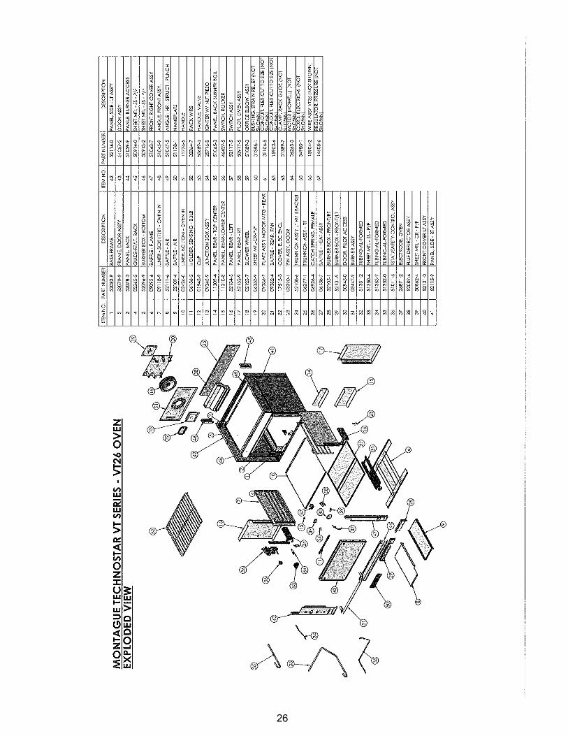
26

27

NOTES

NOTES


(REV. A) P/N 52455-7 5/11