Quick Disconnect Couplings & Hydraulic Valves Quick Disconnect ...

U 39 San Francisco, California
Revised Cal. P.U.C. Sheet No. 45715-E Cancelling Revised Cal. P.U.C. Sheet No. 41008-E*
Electric Sample Form No. 79-1174-02 Sheet 1
Rule 21 Generator Interconnection Application
Advice 5501-E-B Issued by Submitted November 8, 2019
Decision 19-01-030 Robert S. Kenney Effective January 6, 2020
Vice President, Regulatory Affairs Resolution
Please Refer to Attached Sample Form

RULE 21 GENERATOR INTERCONNECTION APPLICATION
(Form 79-1174-02)
Automated Document, Preliminary Statement Part A Page 1 of 5 Form 79-1174-02 Advice 5501-E-B November 2019
Part I - Introduction and Overview
A. Applicability: This Generating Facility Interconnection Application (Application) is used to request the interconnection to Pacific Gas and Electric Company’s (PG&E) Electric System (over which the California Public Utilities Commission (CPUC) has jurisdiction) one or more of the following1 tariffs:
(1) Non-Exporting Generating Facilities; (2) NEM2 Solar (PV) (other than PV 30 KW or less)2; or RPS Generating Facilities (3) NEM2 California Dept. of Corrections & Rehabilitation (4) NEM2A – NEM2 Load Aggregation (under Schedule NEM2) (5) NEM2MT- generating facilities subject to multiple tariff treatment (6) RES-BCT (Renewable Energy Self-Generation Bill Credit Transfer) Generating Facilities; (7) NEMFC / NEMFCA Net Energy Metering for Fuel Cells (8) NEM2V – Virtual Net Energy Metering (9) NEMVMASH (on a single Service Delivery Point, or for a Low Income Development)
Refer to PG&E’s Electric Rule 21 and program tariffs to determine the specific requirements for interconnecting a Generating Facility. Capitalized terms used in this Application, and not otherwise defined herein, shall have the same meanings as defined in PG&E’s Rule 21 and Rule 1. Except as noted in the next paragraph, this Application may be used for any Generating Facility to be operated by, or for, a Customer and/or Interconnection Customer to supplement or serve part or all of its electric energy requirements that would otherwise be provided by PG&E, including distributed generation, cogeneration, emergency, backup, standby generation, and certain Net Energy Metered Generating Facilities. While Customers operating Generating Facilities isolated from PG&E’s Electric System are not obligated to enter into an Interconnection Agreement with PG&E, parts of this Application will still need to be completed to satisfy PG&E’s notice requirements for operating an isolated Generating Facility as specified in the California Health and Safety Code Section 119085 (b).
This Application may not be used to apply for interconnecting Generating Facilities used to participate in transactions where all, or a portion of, the electrical output of the Generating Facility is scheduled with the California Independent System Operator (CAISO). Such transactions may be subject to the jurisdiction of the Federal Energy Regulatory Commission (FERC) and require a different application available from PG&E.
This Application is not applicable for incentives and/or rebates offered by the Energy Resources Conservation and Development Commission (CEC), the CPUC or any other entity. Please contact those agencies directly or on their respective websites:
www.energy.state.ca.us and www.cpuc.ca.gov.
B. Guidelines and Steps for Interconnection: This Application must be completed and sent to PG&E along with the additional information indicated in Part II below to initiate PG&E’s interconnection review of
1 Also when included with Energy Storage (e.g., batteries), or when operating under the provisions of PU
Code 218, where permitted. 2 For Net Energy Metering Customers with Solar and/or Wind Electric Generating Facilities less than 30 kW
that are not paired with Energy Storage, simpler, shorter forms are available from PG&E (i.e., Forms 79-1151-02 A and B). These forms are available on PG&E’s website at http://www.pge.com/gen.

RULE 21 GENERATOR INTERCONNECTION
APPLICATION (Form 79-1174-02)
Automated Document, Preliminary Statement Part A Page 2 of 5 Form 79-1174-02 Advice 5501-E-B November 2019
the proposed Generating Facility. When applicable per Rule 21, unless exempted by CPUC Decision, a non-refundable Interconnection Request fee shall be invoiced and must be paid by Interconnection Customer. Pursuant to PG&E’s Rule 21, there may be additional study and other costs; see PG&E’s Rule 21, Sections E.2.c and E.3., for more information regarding interconnection of a generator to PG&E’s Electric System.
This document is only an Application. Upon acceptance of the Generating Facilities, PG&E will prepare an Interconnection Agreement for execution by the Interconnection Customer, the party that will be responsible for the Generating Facility. PG&E may also require an inspection and testing of the Generating Facility and installation of any related Interconnection Facilities prior to giving the Interconnection Customer written authorization to operate in parallel. Unauthorized Parallel Operation may be dangerous and may result in injury to persons and/or may cause damage to equipment and/or property for which a Interconnection Customer/Customer may be liable!
Please note, other approvals may need to be acquired, and/or other agreements may need to be formed with PG&E or regulatory agencies, such as the Air Quality Management Districts and local governmental building and planning commissions, prior to operating a Generating Facility. PG&E’s authorization to operate in parallel does not satisfy the need for an Interconnection Customer to acquire such other approvals.
Introduction and Overview
Part II – Describing the Generating Facility and Host Customer’s Electrical Facilities
Required Documents: Each of the following documents is required to be submitted before this application will be processed. Drawings must conform to accepted engineering standards and must be legible. Electronic documents are preferred.
1. A Single-line drawing showing the electrical relationship and descriptions of the significant electrical components such as the primary switchgear, secondary switchboard, protective relays, transformers, generators, circuit breakers, with operating voltages, capacities, and protective functions of the Generating Facility, the Customer’s loads, and the interconnection with PG&E’s Electric System. Please show the location of all required net generation electric output meter(s) and the A.C. manual operated disconnect switch on the single line drawing, when required.
2. Site plans and diagrams showing the physical relationship of the significant electrical components of the Generating Facility such as generators, transformers, primary switchgear/secondary switchboard, and control panels, the Customer’s loads and the interconnection with PG&E’s Electric System. Please show the location of all required net generation electric output meter(s) and the A.C. manual operated disconnect switch on the site plans, when required.
3. Disconnect Switch Specification Sheet - as required in Rule 21 Section H.1.d, along with the disconnect switch specification sheet.
PG&E allows only one AC Disconnect for a generating facility but does makes exceptions upon review and approval. Please provide a Variance Letter explaining why multiple AC disconnect switches are needed. This Variance Request will be reviewed in parallel with the Engineering Review.

RULE 21 GENERATOR INTERCONNECTION
APPLICATION (Form 79-1174-02)
Automated Document, Preliminary Statement Part A Page 3 of 5 Form 79-1174-02 Advice 5501-E-B November 2019
4. Variance Request - A variance request will be required for anything outside Electric Rule 213, PG&E’s Greenbook4, or PG&E’s Distribution or Transmission Interconnection Handbooks5,6 stated requirements. (See links below)
5. Transformer nameplate information - Provide transformer nameplate information (voltages, capacity, winding arrangements, connections, impedance, et cetera), if transformers are used to interconnect the Generating Facility with PG&E’s Electric System,
6. Transfer switch/scheme documentation - If used to interconnect the Generating Facility with PG&E Electric System, Documentation shall include component descriptions, capacity ratings, and a technical description of how the transfer scheme is intended to operate.
7. Protective relay documentation If used to control the interconnection, documentation shall include protection diagrams or elementary drawings showing relay wiring and connections, proposed relay settings, and a description of how the protection scheme is intended to function.
Part III Application Appendices
Application Instructions: Complete this application for the complete Generating Facility and enter this information into PG&E’s web-based form. (PG&E strongly recommends preparing all information and materials before starting the online application.) The online web-based form can be found at:
http://www.pge.com/mybusiness/customerservice/nonpgeutility/generateownpower/distributedgeneration/generationrule21/
Questions concerning PG&E's Online Application process can be directed to the Electric Generation Interconnection Department at [email protected].
For each new generating facility you are applying to interconnect, please complete and submit the applicable appendices.
3 Rule 21 can be found at: http://www.pge.com/tariffs/tm2/pdf/ELEC_RULES_21.pdf 4 PG&E’s Greenbook can be found at: http://www.pge.com/greenbook/ 5 Distribution Interconnection Handbook (DIH) can be found at: http://www.pge.com/en/mybusiness/services/nonpge/generateownpower/distributedgeneration/interconnectionhandbook/index.page 6 Transmission Interconnection Handbook (TIH) can be found at: http://www.pge.com/en/mybusiness/services/nonpge/electrictransmission/contractstariffs/handbook/index.page

RULE 21 GENERATOR INTERCONNECTION
APPLICATION (Form 79-1174-02)
Automated Document, Preliminary Statement Part A Page 4 of 5 Form 79-1174-02 Advice 5501-E-B November 2019
Part IV Attachments / On-Line Form - Overview
Table 1 - Summary of the attachment to this form.
Attachment Project Type
1 INFO Customer Project Information
EX
PO
RT
2 NX Non Export
3 EX Export
TE
CH
NO
LO
GY
4 T1 Solar (PV) Only
5 T2 Wind Only
6 T3 Machine-Based Only
7 T4 Fuel Cell
8 T5 Energy Storage Only
TA
RIF
F P
RO
GR
AM
9 P1 RES-BCT
10 P2 NEM2A
11 P3 NEMFCA
12 P4 NEM2V
13 P5 NEMVMASH
14 P6 NEMVMASH Development

RULE 21 GENERATOR INTERCONNECTION
APPLICATION (Form 79-1174-02)
Automated Document, Preliminary Statement Part A Page 5 of 5 Form 79-1174-02 Advice 5501-E-B November 2019
Table 2 below summarizes which attachments to this form will be required for each tariffed program.
Table 2 – New Application Form/Attachments as they apply to PG&E’s Various Tariffed Programs
Category
Non-E
xp
ort
NE
ME
XP
RE
S-B
CT
NE
M2A
NE
MF
C
NE
M2V
NE
MV
MA
SH
Main (79-1184) Customer info
INFO Customer & Project info
Rule 21 - must complete one of these Attachments
NX Non-export
EX Export
Each generating facility must complete one corresponding to technology
T1 Solar T2 Wind T3 Machine (1) (1) (1) (1) T4 Fuel Cell (1) (1) (1) (2) (1) T5 Storage (3) (3) (3) (3)
Complete Attachment that corresponds to tariff program for a generating facility
P1 RES-BCT P2 NEM2A
P3 Fuel Cell Aggregation
P4 NEM2V
P5 NEMVMASH Single building
P6 NEMVMASH development
Black – must be complete. Grey – at least one option in category must be selected Note (1) – must be fueled with a renewable (RPS-Eligible) fuel. Note (2) – may be fueled with a non-renewable fuel. Note (3) – treatment consistent with Decision 14-05-033, if NEM paired. If an applicant’s project has multiple generating facilities, they would need to complete all forms/screens relevant for each generating facility in technology and tariff program (e.g. for NEM2MT).
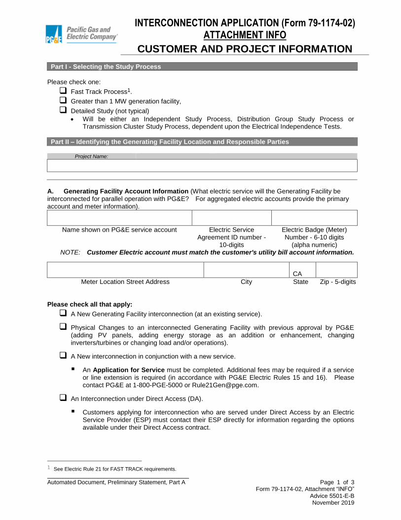
INTERCONNECTION APPLICATION (Form 79-1174-02)
ATTACHMENT INFO
CUSTOMER AND PROJECT INFORMATION
Automated Document, Preliminary Statement, Part A Page 1 of 3
Form 79-1174-02, Attachment “INFO” Advice 5501-E-B November 2019
Part I - Selecting the Study Process
Please check one:
❑ Fast Track Process1.
❑ Greater than 1 MW generation facility,
❑ Detailed Study (not typical)
• Will be either an Independent Study Process, Distribution Group Study Process or Transmission Cluster Study Process, dependent upon the Electrical Independence Tests.
Part II – Identifying the Generating Facility Location and Responsible Parties
Project Name:
A. Generating Facility Account Information (What electric service will the Generating Facility be interconnected for parallel operation with PG&E? For aggregated electric accounts provide the primary account and meter information).
Name shown on PG&E service account Electric Service Agreement ID number -
10-digits
Electric Badge (Meter) Number - 6-10 digits
(alpha numeric) NOTE: Customer Electric account must match the customer's utility bill account information.
CA
Meter Location Street Address City State Zip - 5-digits
Please check all that apply:
❑ A New Generating Facility interconnection (at an existing service).
❑ Physical Changes to an interconnected Generating Facility with previous approval by PG&E (adding PV panels, adding energy storage as an addition or enhancement, changing inverters/turbines or changing load and/or operations).
❑ A New interconnection in conjunction with a new service.
▪ An Application for Service must be completed. Additional fees may be required if a service or line extension is required (in accordance with PG&E Electric Rules 15 and 16). Please contact PG&E at 1-800-PGE-5000 or [email protected].
❑ An Interconnection under Direct Access (DA).
▪ Customers applying for interconnection who are served under Direct Access by an Electric Service Provider (ESP) must contact their ESP directly for information regarding the options available under their Direct Access contract.
1 See Electric Rule 21 for FAST TRACK requirements.

INTERCONNECTION APPLICATION (Form 79-1174-02)
ATTACHMENT INFO
CUSTOMER AND PROJECT INFORMATION
Automated Document, Preliminary Statement, Part A Page 2 of 3
Form 79-1174-02, Attachment “INFO” Advice 5501-E-B November 2019
❑ An Interconnection under Community Choice Aggregation Service (CCA Service).
▪ Customers applying for interconnection who are served under Community Choice Aggregation Service (CCA Service) by a Community Choice Aggregator (CCA) must contact their CCA directly for information regarding the options available under their CCA Service Program.
❑ An interconnected non-exporting Generating Facility (load always exceeds generation).
B. Customer Account Contact Information -
Mailing Address
City State Zip - 5-digits
( ) -_______
( ) -_______
Business Phone Home Phone Fax Email
C. Contractor Information (Must be completed even if Contractor will not serve as a PG&E contact).
Contact Company Name
Mailing Address
City State Zip - 5-digits
( ) -
( ) -
Business Phone Fax Email
Yes No
Does Contractor have Contractors State License Board (CSLB) Number?
Contractors State License Board Number
D. Project Contact Information (Who is the project manager for this Generating Facility?)
Contact Company Name
Mailing Address

INTERCONNECTION APPLICATION (Form 79-1174-02)
ATTACHMENT INFO
CUSTOMER AND PROJECT INFORMATION
Automated Document, Preliminary Statement, Part A Page 3 of 3
Form 79-1174-02, Attachment “INFO” Advice 5501-E-B November 2019
City State Zip - 5-digits
( ) -
( ) -
Business Phone Fax Email
What is the maximum 3-phase fault current that will be contributed by the Generating Facility to a 3-phase fault at the Point of Common Coupling (PCC)? (If the Generating Facility is single phase in design, please provide the contribution for a line-to-line fault).
Please indicate the short circuit interrupting rating of the host Customer facility’s service panel:
______________ Amps
_____________ Amps
Refer to PG&E’s Rule 21, Section G, for significance and additional information. To determine this value, any transformers and/or significant lengths of interconnecting conductor used between each of the Generators (if there are more than one) that make up the Generating Facility and the PCC must be taken into account. The details, impedance, and arrangement of such transformers and interconnecting conductors should be shown on the single-line diagram that is provided. Consult an electrical engineer or the equipment supplier if assistance is needed in answering this question.
It is expected that most Applicants will want to reserve the flexibility to operate any or all of their Generators in parallel. If the design of the proposed Generating Facility limits the amount of generation that may be interconnected at any time to PG&E’s Electric System, please describe the assumptions used in calculating the maximum fault current contribution value. For Customer applying for interconnection under Schedules i) NEM2 – Net Energy Metering Service (including NEM2A – Load Aggregation,. Or NEM2MT- Multiple Tariff- with a NEM2 eligible generator), or ii) NEM2V – Virtual Net Energy Metering Service, or iii) NEM2VMS- Virtual Net Energy Metering For Multifamily Affordable Housing (MASH/NSHP) With Solar Generator(s), please note, pursuant to California Public Utilities Commission Decision (D.) 16-01-044: CEC Listed In order to promote the safety and reliability of the customer’s Generating Facility, the applicant certifies that as a part its request for NEM2, that all major solar system components are on the verified equipment list maintained by the California Energy Commission and certifies that other equipment, as determined by PG&E, has safety certification from a nationally recognized testing laboratory. Warranties or Service Agreements Applicant certifies as a part of its interconnection request for NEM2 that: (i) a warranty of at least 10 years has been provided on all equipment and on its installation, or (ii) a 10-year service warranty or executed “agreement” has been provided ensuring proper maintenance and continued system performance. Interconnection Fees Customers on this tariff must pay for the interconnection of their Generation Facilities as provided in Electric Rule 21.
INTERCONNECTION APPLICATION (Form 79-1174-02) ATTACHMENT NX
NON-EXPORT
Automated Document, Preliminary Statement, Part A Page 1 of 3 Form 79-1174-02, Attachment NX
Advice 5501-E-B November 2019
Interconnection Agreement Type
Please select one option below:
□ Non-Export A Generating Facility Interconnection Agreement that provides for parallel operation of
the Generating Facility, but does not provide for exporting power to PG&E’s Electric System. This non-export agreement, however does allow the occasional and uncompensated export of energy to PG&E’s Electric System for less than 2 seconds in duration.
□ Uncompensated Export A Generating Facility Interconnection Export Addendum that provides for
parallel operation of the Generating Facility and the occasional, continuous, non-compensated, export of generator facilities sized 2 MW or less to PG&E’s Electric System. Continuous export is export greater than 60 seconds in duration. This addendum must be executed in concert with the generating facility interconnection agreement.
Third Party Generating Facility Ownership
□ Third Party Owned Generating Facility A Generating Facility Interconnection Agreement that
provides for parallel operation of the 3rd Party owned Generating Facility, but does not provide for exporting energy to PG&E’s Electric System; as well as a Customer Generation Agreement that defines the relationship between the Customer whose name appears on PG&E’s electric service account. If this option is chosen, please complete the Third Party Generating Facility Ownership section below.
Customer Generation Agreement (CGA) (for 3rd Party Generator on Premises) Information (Please identify the PG&E Customer of Record where Generating Facility will be installed). CGA is not applicable to Net Energy Metering 2 (NEM2) Applicants because PG&E and the Customer, not the 3rd Party if any, must enter into the Net Energy Metering Interconnection Agreement.
Company Name to be entered on CGA Legal Title of Host Facility to be entered on CGA
Person Executing the CGA Title of Person Executing the CGA
( ) ____ - _______
Mailing Address Phone E-Mail
Generating Facility Interconnection Agreement (GFIA) for 3rd Party Owner – GFIA Information
□ Generating Facility Interconnection Agreement (GFIA) for 3rd Party Owner will be executed
by Contractor Please identify the Party that will own the Generating Facility. This Section is not applicable to Net Energy Metering 2 (NEM2) Applicants because PG&E and the Customer, not the 3rd Party if any, must enter into the Net Energy Metering 2 Interconnection
Agreement.

INTERCONNECTION APPLICATION (Form 79-1174-02) ATTACHMENT NX
NON-EXPORT
Automated Document, Preliminary Statement, Part A Page 2 of 3 Form 79-1174-02, Attachment NX
Advice 5501-E-B November 2019
Company Name to be entered on GFIA Legal Title of Company to be entered on GFIA
( ) ____ - _______
Mailing Address Phone E-Mail
Part II – Generating Facility Operational Details
Operating Modes: Please select one box below:
□ Parallel Operation: The Generating Facility will interconnect and operate “in parallel” with PG&E’s
Electric System for more than one (1) second.
Please supply all of the information requested for the Generating Facility. Be sure to supply adequate information including diagrams and written descriptions regarding the protective relays that will be used to detect faults or abnormal operating conditions on PG&E’s Electric System.
□ Inadvertent Export: The Generating Facility will interconnect and operate, providing unscheduled
and uncompensated export of real power for a duration exceeding two (2) seconds but fewer than sixty (60) seconds. The expected frequency of “inadvertent export” occurrences should be less than two occurrences per 24-hour period. Protective Functions, technical requirements and operational limitations are described in Rule 21, Section M.
Be sure to supply adequate information including diagrams and written descriptions regarding the switching device or scheme that will be used to limit the parallel operation period to one second or less. Please also describe the back up or protective device and controls that will trip the Generating Facility should the transfer switch or scheme not complete the transfer in one second or less.
□ Momentary Parallel Operation (MP): The Generating Facility will interconnect and operate on a
“momentary parallel” basis with PG&E’s Electric System for a duration of one (1) second or less through transfer switches or operating schemes specifically designed and engineered for such operation.
Be sure to supply adequate information including diagrams and written descriptions regarding the switching device or scheme that will be used to limit the parallel operation period to one second or less. Please also describe the back up or protective device and controls that will trip the Generating Facility should the transfer switch or scheme not complete the transfer in one second or less.
□ Isolated Operation (I): The Generating Facility will be “isolated” and prevented from becoming
interconnected with PG&E’s Electric System through a transfer switch or operating scheme specifically designed and engineered for such operation.
Be sure to supply adequate information including diagrams and written descriptions regarding the isolating switching device or scheme that will be used to prevent the Generating Facility from operating in parallel with PG&E’s Electric System.

INTERCONNECTION APPLICATION (Form 79-1174-02) ATTACHMENT NX
NON-EXPORT
Automated Document, Preliminary Statement, Part A Page 3 of 3 Form 79-1174-02, Attachment NX
Advice 5501-E-B November 2019
Parallel and Inadvertent Export Options Please select one box below:
❑ A reverse-power protection device will be installed to measure any export of power and trip the Generating Facility or open an intertie breaker to isolate the Generating Facility if limits are exceeded.
❑ An under-power protection device will be installed to measure the inflow of power and trip or reduce the output of the Generating Facility if limits are not maintained.
❑ The Generating Facility Interconnection Facility equipment has been certified as non-islanding and the incidental export of power will be limited by the design of the interconnection. If this option is to be used, the nominal ampere rating of the service entrance equipment (service panel rating) that is used by the host Customer facility is: ________________________________.
❑ The Gross Nameplate Rating of the Generating Facility will not exceed 50% of the host Customer facility’s minimum electrical load over the past 12 months. If this option is to be used, the minimum load of the host Customer facility must be stated in the space provided above.
The Generating Facility completely offset their facility load by being (a) optimally sized to meet their peak demand with load following functionality on the Generator controls and (b) ensuring conditional (inadvertent) export of electric power from the Generation Facility to Distribution Provider’s Distribution or Transmission System occurs no more frequently than twice in any 24 hour period and the exports are greater than 2 seconds but no more than more than 60 seconds.
With the approval of PG&E, a Producer that wishes to retain the option to export power from a Generating Facility to PG&E’s Electric System may use a different protection scheme that provides for the detection of faults and other abnormal operating conditions.
Please indicate:
❑ Standby / Emergency / Backup – Where the Generating Facility will normally be operated only
when PG&E’s electric service is not available.
❑ Qualifying Facility (QF) Status will be obtained from the FERC for this Generating Facility.
Instructions and Notes: Parties operating Generating Facilities (QF) complying with all of the requirements for qualification as either a small power production facility or cogeneration facility pursuant to the regulations of the FERC (18 Code of Federal Regulations Part 292, Section 292.203 et seq.) implementing the Public Utility Regulatory Policies Act of 1978 (16 U.S.C.A. Section 796, et seq.), or any successor requirements for Qualifying Facilities, may seek certification from FERC to have the Generating Facility designated as a Qualifying Facility or “QF.” In summary, QFs are Generating Facilities using renewable or alternative fuels as a primary energy source or facilities that utilize the thermal energy given off by the generation process for some other useful purpose. QFs enjoy certain rights and privileges not available to non-QF Generating Facilities.
QF status is not required to interconnect and operate in parallel with PG&E’s Electric System.
INTERCONNECTION APPLICATION (Form 79-1174-02) ATTACHMENT EX
EXPORT
Automated Document, Preliminary Statement, Part A Page 1 of 1 Form 79-1174-02, Attachment EX
Advice 5501-E-B November 2019
Describing the Export Operation
Interconnection Service Requirements: (Please select one box below)
☐ Existing Service (currently metered PG&E service)
☐ New Generation-only Service (no load other than ancillary required for Generating Facility)
NEMVMASH participants must select either this option or the next
☐ New Generation-only Meter Tap (at location of existing service)
NEM2V applicants must select this option
If new generation-only service is needed, please indicate the requested voltage level: (Please select one box below)
☐ Secondary (up to 480V)
☐ Primary (up to 59 kV)
☐ Transmission (60 kV and up)
Power Export:
Generator Nameplate1 Export (kW) _______________________
Maximum Expected Facility Net Export (kW) ______________________
Applications to interconnect systems located in San Francisco or Oakland may require additional analysis to determine whether or not their proposed installation is on PG&E’s networked secondary system. Networked secondary systems are in place to provide heightened levels of reliability in densely populated areas and may affect the ability of PG&E to interconnect NEM customers.
☐ Is the proposed installation is in San Francisco where the zip code is 94102, 94103, 94104, 94105,
94107, 94108, 94109, 94111 or 94133 or in Oakland where the zip code is 94607 or 94612?
1 Please note that for Generating Facilities larger than 1 MW interconnecting to existing secondary voltage services, the revenue meter may require power loss adjustment.

INTERCONNECTION APPLICATION (Form 79-1174-02)
ATTACHMENT T2
WIND TURBINE TECHNOLOGY
Automated Document, Preliminary Statement, Part A Page 1 of 3
Form 79-1174-02, Attachment T2 Advice 5501-E-B November 2019
Please complete the following table for the specific generator technology indicated.
Instructions
Generator Information Existing
Generator type 1
Existing Generator
type 2
New Generator
type 1
New Generator
type 2
Please indicate the number of each “type” and quantity of Generator being installed
Be sure all Generators classified as one “type” are identical in all respects.
If only one type of Generator is to be used, only one column needs to be completed.
Type: Qty.:
Type:
Qty.:
Type:
Qty.:
Type:
Qty.:
A - Generator/Inverter Manufacturer Enter the brand name of the Generator.
B - Generator/Inverter Model
Enter the model name or number assigned by the manufacturer of the Generator.
C - Generator/Inverter Software Version
If this Generator’s control and or protective functions are dependent on a software program supplied by the manufacturer of the equipment, please provide the version or release number for the software that will be used.
D - Is the Inverter certified?
Applicant has verified that all major solar system components are on the verified equipment list maintained by the California Energy Commission and other equipment, as determined by PG&E, has been verified by the customer as having safety certification from a nationally recognized testing laboratory.
See PG&E’s Rule 21, Section L for additional information regarding Generator certification.
____ Yes ____ No
____ Yes ____ No
____ Yes ____ No
____Yes ____ No
E - Generator Design
Please indicate the design of each Generator.
Designate “Inverter” anytime an inverter is used as the interface between the Generator and the electric system regardless of the primary power production/storage device used.
____ Synch
____ Induct.
____ Inverter
____ Synch
____ Induct.
____ Inverter
____ Synch
____ Induct.
____ Inverter
____ Synch
____ Induct.
____ Inverter

INTERCONNECTION APPLICATION (Form 79-1174-02)
ATTACHMENT T2
WIND TURBINE TECHNOLOGY
Automated Document, Preliminary Statement, Part A Page 2 of 3
Form 79-1174-02, Attachment T2 Advice 5501-E-B November 2019
Generator Information Existing
Generator type 1
Existing Generator
type 2
New Generator
type 1
New Generator
type 2
F - Gross Nameplate Rating (kVA)
This is the capacity value normally supplied by the manufacturer and stamped on the Generator’s nameplate.
This value is not required where the manufacturer provides only a kW rating. However, where both kVA and kW values are available, please indicate both.
G - Operating Voltage
This value should be the voltage rating designated by the manufacturer and used in this Generating Facility.
Please indicate phase-to-phase voltages for 3-phase installations.
See PG&E’s Rule 21, Section H.2.b. and Table H.1., for additional information.
H - Power Factor Rating
This value should be the nominal power factor rating designated by the manufacturer for the Generator.
See PG&E’s Rule 21, Section H.2.i. for additional information.
I - PF Adjustment Range
Where the power factor of the Generator is adjustable, please indicate the maximum and minimum operating values.
See PG&E’s Rule 21, Section H.2.i.
J - Wiring Configuration
Please indicate whether the Generator is a single-phase or three-phase device. See PG&E’s Rule 21, Section H.3.
K - (MP) 3-Phase Winding Configuration
(Choose One)
For three-phase generating units, please indicate the configuration of the Generator’s windings or inverter systems.
__3 Wire Delta
__3 Wire Wye
__4 Wire Wye
__3 Wire Delta
__3 Wire Wye
__4 Wire Wye
__3 Wire Delta
__3 Wire Wye
__4 Wire Wye
__3 Wire Delta
__3 Wire Wye
__4 Wire Wye

INTERCONNECTION APPLICATION (Form 79-1174-02)
ATTACHMENT T2
WIND TURBINE TECHNOLOGY
Automated Document, Preliminary Statement, Part A Page 3 of 3
Form 79-1174-02, Attachment T2 Advice 5501-E-B November 2019
Generator Information Existing
Generator type 1
Existing Generator
type 2
New Generator
type 1
New Generator
type 2
L - (MP) Neutral Grounding System Used
(Choose One)
Wye connected generating units are often grounded – either through a resistor or directly, depending upon the nature of the electrical system to which the Generator is connected.
If the grounding method used at this facility is not listed, please attach additional descriptive information.
___ Ungrounded
___ Solidly Grounded
___ Ground Resistor
___ Ohms
___ Ungrounded
___ Solidly Grounded
___ Ground Resistor
___ Ohms
___ Ungrounded
___ Solidly Grounded
___ Ground Resistor
___ Ohms
___ Ungrounded
___ Solidly Grounded
___ Ground Resistor
___ Ohms
M - Induction Generators Only:
Locked Rotor Current: Stator Resistance:
Stator Leakage Reactance: Rotor Resistance:
Rotor Leakage Reactance:
If the Generator is of an induction design, please provide the “locked rotor current” value supplied by the manufacturer.
If this value is not available, the stator resistance, stator leakage reactance, rotor resistance, rotor leakage reactance values supplied by the manufacturer may be used to determine the locked rotor current.
If the Generator’s Gross Nameplate Capacity is 10 MW or greater, PG&E may request additional data to better model the nature and behavior of the Generator with relation to its Electric System.
_____________ (Amps)
__________(%) __________(%) __________(%) __________(%)
_____________ (Amps)
__________(%) __________(%) __________(%) __________(%)
____________ (Amps)
_________(%) _________(%) _________(%) _________(%)
____________ (Amps)
_________(%) _________(%) _________(%) _________(%)
N - Short Circuit Current Produced by Generator: ________
(Amps) ________
(Amps) ________
(Amps) ________
(Amps)
O - AC Disconnect
For systems requiring an AC Disconnect only, please include the requested information about the AC Disconnect.
See PG&E’s Rule 21, Section H.1.d
Located within 10 feet of the PG&E meter?
____________ Manufacturer
__________ Model #
__________ Rating (amps)
____ Yes
____ No
____________ Manufacturer
__________ Model #
__________ Rating (amps)
____ Yes
____ No
____________ Manufacturer
__________ Model #
__________ Rating (amps)
____ Yes
____ No
____________ Manufacturer
__________ Model #
__________ Rating (amps)
____ Yes
____ No
P - Lineside Tap
PG&E has special requirements for a lineside tap.
Contact PG&E at: [email protected] for more information.
____ Yes
____ No
____ Yes
____ No
____ Yes
____ No
____ Yes
____ No
Q – Warranty or Service Agreement
Applicant has verified that (i) a warranty of at least 10 years has been provided on all equipment and on its installation, or (ii) have a 10-year service warranty or executed “agreement” ensuring proper maintenance and continued system performance.
____ Yes
____ No
____ Yes
____ No
____ Yes
____ No
____ Yes
____ No

INTERCONNECTION APPLICATION (Form 79-1174-02)
ATTACHMENT T3
MACHINE-BASED TECHNOLOGY
Automated Document, Preliminary Statement, Part A Page 1 of 4
Form 79-1174-02, Attachment T3 Advice 5501-E-B November 2019
Please complete the following table for the specific generator technology indicated.
Instructions
Generator Information Existing
Generator type 1
Existing Generator
type 2
New Generator
type 1
New Generator
type 2
Please indicate the number of each “type” and quantity of Generator being installed.
Be sure all Generators classified as one “type” are identical in all respects.
If only one type of Generator is to be used, only one column needs to be completed.
A - Generator/Inverter Manufacturer Enter the brand name of the Generator.
B - Generator/Inverter Model
Enter the model name or number assigned by the manufacturer of the Generator.
C - Generator/Inverter Software Version
If this Generator’s control and or protective functions are dependent on a software program supplied by the manufacturer of the equipment, please provide the version or release number for the software that will be used.
D - Is the Generator/Inverter certified?
Applicant has verified that all major solar system components are on the verified equipment list maintained by the California Energy Commission and other equipment, as determined by PG&E, has been verified by the customer as having safety certification from a nationally recognized testing laboratory.
See PG&E’s Rule 21, Section L for additional information regarding Generator certification.
____ Yes
____ No
____ Yes
____ No
____ Yes
____ No
____ Yes
____ No
F - Gross Nameplate Rating (kVA)
This is the capacity value normally supplied by the manufacturer and stamped on the Generator’s nameplate.
This value is not required where the manufacturer provides only a kW rating. However, where both kVA and kW values are available, please indicate both.

INTERCONNECTION APPLICATION (Form 79-1174-02)
ATTACHMENT T3
MACHINE-BASED TECHNOLOGY
Automated Document, Preliminary Statement, Part A Page 2 of 4
Form 79-1174-02, Attachment T3 Advice 5501-E-B November 2019
Generator Information Existing
Generator type 1
Existing Generator
type 2
New Generator
type 1
New Generator
type 2
G - Operating Voltage
This value should be the voltage rating designated by the manufacturer and used in this Generating Facility.
Please indicate phase-to-phase voltages for 3-phase installations.
See PG&E’s Rule 21, Section H.2.b. and Table H.1., for additional information.
H - Power Factor Rating
This value should be the nominal power factor rating designated by the manufacturer for the Generator.
See PG&E’s Rule 21, Section H.2.i. for additional information.
I - PF Adjustment Range
Where the power factor of the Generator is adjustable, please indicate the maximum and minimum operating values.
See PG&E’s Rule 21, Section H.2.i.
J - Wiring Configuration
Please indicate whether the Generator is a single-phase or three-phase device. See PG&E’s Rule 21, Section H.3.
K - (MP) 3-Phase Winding Configuration
(Choose One)
For three-phase generating units, please indicate the configuration of the Generator’s windings or inverter systems.
__3 Wire Delta
__3 Wire Wye
__4 Wire Wye
__3 Wire Delta
__3 Wire Wye
__4 Wire Wye
__3 Wire Delta
__3 Wire Wye
__4 Wire Wye
__3 Wire Delta
__3 Wire Wye
__4 Wire Wye
L - (MP) Neutral Grounding System Used (Choose One)
Wye connected generating units are often grounded – either through a resistor or directly, depending upon the nature of the electrical system to which the Generator is connected.
If the grounding method used at this facility is not listed, please attach additional descriptive information.
__ Ungrounded
__ Solidly Grounded
__ Ground Resistor
__ Ohms
__ Ungrounded
__ Solidly Grounded
__ Ground Resistor
__ Ohms
__ Ungrounded
__ Solidly Grounded
__ Ground Resistor
__ Ohms
__ Ungrounded
__ Solidly Grounded
__ Ground Resistor
__ Ohms

INTERCONNECTION APPLICATION (Form 79-1174-02)
ATTACHMENT T3
MACHINE-BASED TECHNOLOGY
Automated Document, Preliminary Statement, Part A Page 3 of 4
Form 79-1174-02, Attachment T3 Advice 5501-E-B November 2019
Generator Information Existing
Generator type 1
Existing Generator
type 2
New Generator
type 1
New Generator
type 2
M – Synchronous Generators Only: If the Generator is of a synchronous design, please provide the synchronous reactance, transient reactance, and subtransient reactance values supplied by the manufacturer. This information is necessary to determine the short circuit contribution of the Generator and as data in load flow and short circuit computer models of PG&E’s Electric System. If the Generator’s Gross Nameplate Capacity is 10 MW or greater, PG&E may request additional data to better model the nature and behavior of the Generator with relation to its Electric System.
Synchronous Reactance:
Transient Reactance:
Subtransient Reactance:
_______ (Xd %) _______ (Xd %) _______ (Xd %)
_______ (Xd %) _______ (Xd %) _______ (Xd %)
_______ (Xd %) _______ (Xd %) _______ (Xd %)
_______ (Xd %) _______ (Xd %) _______ (Xd %)
N - Induction Generators Only:
Locked Rotor Current:
Stator Resistance:
Stator Leakage Reactance:
Rotor Resistance:
Rotor Leakage Reactance:
If the Generator is of an induction design, please provide the “locked rotor current” value supplied by the manufacturer.
If this value is not available, the stator resistance, stator leakage reactance, rotor resistance, rotor leakage reactance values supplied by the manufacturer may be used to determine the locked rotor current.
If the Generator’s Gross Nameplate Capacity is 10 MW or greater, PG&E may request additional data to better model the nature and behavior of the Generator with relation to its Electric System.
_____________ (Amps)
__________(%)
__________(%)
__________(%)
__________(%)
_____________ (Amps)
__________(%)
__________(%)
__________(%)
__________(%)
____________ (Amps)
_________(%)
_________(%)
_________(%)
_________(%)
___________ (Amps)
_________(%)
_________(%)
_________(%)
_________(%)
O - Short Circuit Current Produced by Generator: ________ (Amps)
________ (Amps)
________ (Amps)
________ (Amps)

INTERCONNECTION APPLICATION (Form 79-1174-02)
ATTACHMENT T3
MACHINE-BASED TECHNOLOGY
Automated Document, Preliminary Statement, Part A Page 4 of 4
Form 79-1174-02, Attachment T3 Advice 5501-E-B November 2019
Generator Information Existing
Generator type 1
Existing Generator
type 2
New Generator
type 1
New Generator
type 2
P – For Generators that are Started as a “Motor” Only: This information is needed only for Generators that are started by “motoring” the generator.
See PG&E’s Rule 21, Sections L.3.d. and L.7.b. for significance and additional information.
If this question was answered in Part IV, question C of this Application, it need not be answered here.
1. In-Rush Current: 2. Host Customer’s Service Entrance Panel (Main Panel) Continuous Current Rating:
____________ (Amps)
____________ (Amps)
____________ (Amps)
____________ (Amps)
____________ (Amps)
____________ (Amps)
____________ (Amps)
____________ (Amps)
Q – Prime Mover Type
Please indicate the type and fuel used as the prime mover or source of energy for the Generator.
1 = Natural Gas 2 = Diesel Fueled 3 = Other Fuel
1 2 3
1 2 3
1 2 3
1 2 3
R - AC Disconnect
For systems requiring an AC Disconnect only, please include the requested information about the AC Disconnect.
See PG&E’s Rule 21, Section H.1.d
Located within 10 feet of the PG&E meter?
____________ Manufacturer
__________ Model #
__________ Rating (amps)
____ Yes
____ No
____________ Manufacturer
__________ Model #
__________ Rating (amps)
____ Yes
____ No
____________ Manufacturer
__________ Model #
__________ Rating (amps)
____ Yes
____ No
____________ Manufacturer
__________ Model #
__________ Rating (amps)
____ Yes
____ No
S - Lineside Tap PG&E has special requirements for a lineside tap. Contact PG&E at: [email protected] for more information.
____ Yes
____ No
____ Yes
____ No
____ Yes
____ No
____ Yes
____ No
T – Warranty or Service Agreement
Applicant has verified that (i) a warranty of at least 10 years has been provided on all equipment and on its installation, or (ii) have a 10-year service warranty or executed “agreement” ensuring proper maintenance and continued system performance.
____ Yes
____ No
____ Yes
____ No
____ Yes
____ No
____ Yes
____ No

INTERCONNECTION APPLICATION (Form 79-1174-02)
ATTACHMENT T4
FUEL CELL TECHNOLOGY
Automated Document, Preliminary Statement, Part A Page 1 of 3
Form 79-1174-02, Appendix T4 Advice 5501-E-B November 2019
Please complete the following table for the specific generator technology indicated.
Instructions
Generator Information Existing
Generator type 1
Existing Generator
type 2
New Generator
type 1
New Generator
type 2
Please indicate the number of each “type” and quantity of Generator being installed.
Be sure all Generators classified as one “type” are identical in all respects.
If only one type of Generator is to be used, only one column needs to be completed.
A - Generator/Inverter Manufacturer
Enter the brand name of the Generator.
B - Generator/Inverter Model
Enter the model name or number assigned by the manufacturer of the Generator.
C - Generator/Inverter Software Version
If this Generator’s control and or protective functions are dependent on a software program supplied by the manufacturer of the equipment, please provide the version or release number for the software that will be used.
D - Is the Generator/Inverter certified?
Applicant has verified that all major solar system components are on the verified equipment list maintained by the California Energy Commission and other equipment, as determined by PG&E, has been verified by the customer as having safety certification from a nationally recognized testing laboratory.
See PG&E’s Rule 21, Section L for additional information regarding Generator certification.
____ Yes
____ No
____ Yes
____ No
____ Yes
____ No
____ Yes
____ No

INTERCONNECTION APPLICATION (Form 79-1174-02)
ATTACHMENT T4
FUEL CELL TECHNOLOGY
Automated Document, Preliminary Statement, Part A Page 2 of 3
Form 79-1174-02, Appendix T4 Advice 5501-E-B November 2019
Generator Information Existing
Generator type 1
Existing Generator
type 2
New Generator
type 1
New Generator
type 2
E - Generator Design
Please indicate the design of each Generator.
Designate “Inverter” anytime an inverter is used as the interface between the Generator and the electric system regardless of the primary power production/storage device used.
____ Synch
____ Induct.
____ Inverter
____ Synch
____ Induct.
____ Inverter
____ Synch
____ Induct.
____ Inverter
____ Synch
____ Induct.
____ Inverter
F - Gross Nameplate Rating (kVA)
This is the capacity value normally supplied by the manufacturer and stamped on the Generator’s nameplate.
This value is not required where the manufacturer provides only a kW rating. However, where both kVA and kW values are available, please indicate both.
G - Operating Voltage
This value should be the voltage rating designated by the manufacturer and used in this Generating Facility.
Please indicate phase-to-phase voltages for 3-phase installations.
See PG&E’s Rule 21, Section H.2.b. and Table H.1., for additional information.
H - Power Factor Rating
This value should be the nominal power factor rating designated by the manufacturer for the Generator.
See PG&E’s Rule 21, Section H.2.i. for additional information.
I - PF Adjustment Range
Where the power factor of the Generator is adjustable, please indicate the maximum and minimum operating values.
See PG&E’s Rule 21, Section H.2.i.
J - Wiring Configuration
Please indicate whether the Generator is a single-phase or three-phase device. See PG&E’s Rule 21, Section H.3.
K - (MP) 3-Phase Winding Configuration
(Choose One)
For three-phase generating units, please indicate the configuration of the Generator’s windings or inverter systems.
__3 Wire Delta
__3 Wire Wye
__4 Wire Wye
__3 Wire Delta
__3 Wire Wye
__4 Wire Wye
__3 Wire Delta
__3 Wire Wye
__4 Wire Wye
__3 Wire Delta
__3 Wire Wye
__4 Wire Wye

INTERCONNECTION APPLICATION (Form 79-1174-02)
ATTACHMENT T4
FUEL CELL TECHNOLOGY
Automated Document, Preliminary Statement, Part A Page 3 of 3
Form 79-1174-02, Appendix T4 Advice 5501-E-B November 2019
Generator Information Existing
Generator type 1
Existing Generator
type 2
New Generator
type 1
New Generator
type 2
L - (MP) Neutral Grounding System Used (Choose One)
Wye connected generating units are often grounded – either through a resistor or directly, depending upon the nature of the electrical system to which the Generator is connected.
If the grounding method used at this facility is not listed, please attach additional descriptive information.
__ Ungrounded
__ Solidly Grounded
__ Ground Resistor
__ Ohms
__ Ungrounded
__ Solidly Grounded
__ Ground Resistor
__ Ohms
__ Ungrounded
__ Solidly Grounded
__ Ground Resistor
__ Ohms
__ Ungrounded
__ Solidly Grounded
__ Ground Resistor
__ Ohms
M - Short Circuit Current Produced by Generator: ________ (Amps)
________ (Amps)
________ (Amps)
________ (Amps)
N – Prime Mover Type
Please indicate the type and fuel used as the prime mover or source of energy for the Generator.
1 = Natural Gas 2 = Diesel Fueled 3 = Other Fuel
1 2 3
1 2 3
1 2 3
1 2 3
O - AC Disconnect
For systems requiring an AC Disconnect only, please include the requested information about the AC Disconnect.
See PG&E’s Rule 21, Section H.1.d
Located within 10 feet of the PG&E meter?
____________ Manufacturer
__________
Model # __________
Rating (amps)
____ Yes
____ No
____________ Manufacturer
__________
Model # __________
Rating (amps)
____ Yes
____ No
____________ Manufacturer
__________
Model # __________
Rating (amps)
____ Yes
____ No
____________ Manufacturer
__________
Model # __________
Rating (amps)
____ Yes
____ No
P - Lineside Tap
PG&E has special requirements for a lineside tap.
Contact PG&E at: [email protected]
for more information.
____ Yes
____ No
____ Yes
____ No
____ Yes
____ No
____ Yes
____ No
Q – Warranty or Service Agreement
Applicant has verified that (i) a warranty of at least 10 years has been provided on all equipment and on its installation, or (ii) have a 10-year service warranty or executed “agreement” ensuring proper maintenance and continued system performance.
____ Yes
____ No
____ Yes
____ No
____ Yes
____ No
____ Yes
____ No

INTERCONNECTION APPLICATION (Form 79-1174-02)
ATTACHMENT T5
ENERGY STORAGE TECHNOLOGY
Automated Document, Preliminary Statement, Part A Page 1 of 5
Form 79-1174-02, Attachment T5 Advice 5501-E-B November 2019
Please complete the following table for the specific generator technology indicated.
Instructions
Generator Information Existing
Generator type 1
Existing Generator
type 2
New Generator
type 1
New Generator
type 2
Please indicate the number of each “type” and quantity of Generator being installed.
Be sure all Generators classified as one “type” are identical in all respects.
If only one type of Generator is to be used, only one column needs to be completed.
A - Generator/Inverter Manufacturer
Enter the brand name of the Generator.
B - Generator/Inverter Model
Enter the model name or number assigned by the manufacturer of the Generator.
C - Generator/Inverter Software Version
If this Generator’s control and or protective functions are dependent on a software program supplied by the manufacturer of the equipment, please provide the version or release number for the software that will be used.
D - Is the Generator/Inverter certified?
Applicant has verified that all major solar system components are on the verified equipment list maintained by the California Energy Commission and other equipment, as determined by PG&E, has been verified by the customer as having safety certification from a nationally recognized testing laboratory.
See PG&E’s Rule 21, Section L for additional information regarding Generator certification.
____ Yes ____ No
____ Yes ____ No
____ Yes ____ No
____ Yes ____ No
E - Generator Design
Please indicate the design of each Generator.
Designate “Inverter” anytime an inverter is used as the interface between the Generator and the electric system regardless of the primary power production/storage device used.
____ Synch
____ Induct.
____ Inverter
____ Synch
____ Induct.
____ Inverter
__ Synch
____ Induct.
____ Inverter
____ Synch
____ Induct.
____ Inverter

INTERCONNECTION APPLICATION (Form 79-1174-02)
ATTACHMENT T5
ENERGY STORAGE TECHNOLOGY
Automated Document, Preliminary Statement, Part A Page 2 of 5
Form 79-1174-02, Attachment T5 Advice 5501-E-B November 2019
Generator Information Existing
Generator type 1
Existing Generator
type 2
New Generator
type 1
New Generator
type 2
F - Gross Nameplate Rating (kVA)
This is the capacity value normally supplied by the manufacturer and stamped on the Generator’s nameplate.
This value is not required where the manufacturer provides only a kW rating. However, where both kVA and kW values are available, please indicate both.
G - Energy Storage Electrical Source Function (in addition, please complete section: “Additional Information Required for Energy Storage”)
Max kWh Capacity:
Rated kW Discharge:
__________
Max kWh Capacity:
Rated kW Discharge:
__________
Max kWh Capacity:
Rated kW Discharge:
__________
Max kWh Capacity:
Rated kW Discharge:
__________
H - Operating Voltage
This value should be the voltage rating designated by the manufacturer and used in this Generating Facility.
Please indicate phase-to-phase voltages for 3-phase installations.
See PG&E’s Rule 21, Section H.2.b. and Table H.1., for additional information.
I - Power Factor Rating
This value should be the nominal power factor rating designated by the manufacturer for the Generator.
See PG&E’s Rule 21, Section H.2.i. for additional information.
J - PF Adjustment Range
Where the power factor of the Generator is adjustable, please indicate the maximum and minimum operating values.
See PG&E’s Rule 21, Section H.2.i.
K - Wiring Configuration
Please indicate whether the Generator is a single-phase or three-phase device. See PG&E’s Rule 21, Section H.3.

INTERCONNECTION APPLICATION (Form 79-1174-02)
ATTACHMENT T5
ENERGY STORAGE TECHNOLOGY
Automated Document, Preliminary Statement, Part A Page 3 of 5
Form 79-1174-02, Attachment T5 Advice 5501-E-B November 2019
Generator Information Existing
Generator type 1
Existing Generator
type 2
New Generator
type 1
New Generator
type 2
L - (MP) 3-Phase Winding Configuration (Choose One)
For three-phase generating units, please indicate the configuration of the Generator’s windings or inverter systems.
__3 Wire Delta
__3 Wire Wye
__4 Wire Wye
__3 Wire Delta
__3 Wire Wye
__4 Wire Wye
__3 Wire Delta
__3 Wire Wye
__4 Wire Wye
__3 Wire Delta
__3 Wire Wye
__4 Wire Wye
M - (MP) Neutral Grounding System Used (Choose One)
Wye connected generating units are often grounded – either through a resistor or directly, depending upon the nature of the electrical system to which the Generator is connected.
If the grounding method used at this facility is not listed, please attach additional descriptive information.
__ Ungrounded
__ Solidly Grounded
__ Ground Resistor
__ Ohms
__ Ungrounded
__ Solidly Grounded
__ Ground Resistor
__ Ohms
__ Ungrounded
__ Solidly Grounded
__ Ground Resistor
__ Ohms
__ Ungrounded
__ Solidly Grounded
__ Ground Resistor
__ Ohms
N - Short Circuit Current Produced by Generator:
________ (Amps)
________ (Amps)
________ (Amps)
________ (Amps)
O – Prime Mover Type
Please indicate the type and fuel used as the prime mover or source of energy for the Generator.
1 = Natural Gas
2 = Diesel Fueled
3 = Other Fuel
1 2 3
1 2 3
1 2 3
1 2 3
P - AC Disconnect
For systems requiring an AC Disconnect only, please include the requested information about the AC Disconnect.
See PG&E’s Rule 21, Section H.1.d
Located within 10 feet of the PG&E meter?
____________ Manufacturer
__________ Model #
__________ Rating (amps)
____ Yes
____ No
____________ Manufacturer
__________ Model #
__________ Rating (amps)
____ Yes
____ No
____________ Manufacturer
__________ Model #
__________ Rating (amps)
____ Yes
____ No
____________ Manufacturer
__________ Model #
__________ Rating (amps)
____ Yes
____ No

INTERCONNECTION APPLICATION (Form 79-1174-02)
ATTACHMENT T5
ENERGY STORAGE TECHNOLOGY
Automated Document, Preliminary Statement, Part A Page 4 of 5
Form 79-1174-02, Attachment T5 Advice 5501-E-B November 2019
Generator Information Existing
Generator type 1
Existing Generator
type 2
New Generator
type 1
New Generator
type 2
Q - Energy Storage (ES) System
(For important sizing information related to DC-Coupled
configurations, see sizing note below).
______________ Manufacturer
______________
Model # ______________ Quantity of Units
______________ Manufacturer
______________
Model # _____________ Quantity of Units
______________ Manufacturer
______________
Model # _____________ Quantity of Units
______________ Manufacturer
______________
Model #
____________ Quantity of Units
R - Lineside Tap
PG&E has special requirements for a lineside tap.
Contact PG&E at: [email protected] for more information.
____ Yes
____ No
____ Yes
____ No
____ Yes
____ No
____ Yes
____ No
S – Warranty or Service Agreement
Applicant has verified that (i) a warranty of at least 10 years has been provided on all equipment and on its installation, or (ii) have a 10-year service warranty or executed “agreement” ensuring proper maintenance and continued system performance.
____ Yes
____ No
____ Yes
____ No
____ Yes
____ No
____ Yes
____ No
Energy Storage Charging Function:
Rated Charge Demand (Load): ____________ kW
Estimated annual Net Energy Usage* of the energy storage device(s): ____ ____ kWh
*Net Energy usage = (kWh input, including charging, storage device auxiliary loads and losses) – (kWh output including discharging)
Will the Distribution Grid be used to charge the storage device: Yes No
If no: Provide technical description of control systems including (e.g. Nationally-certified piece of equipment, Relays/metering):
Source of energy for Charging:
Mechanism to prevent charging from the Distribution System:
If Yes: Will charging the storage device(s) increase the host facility’s existing peak load demand:
Yes No
If Yes: Provide the following loading information:
Amount of added peak demand: kW
If no: Provide technical description of controls systems including:
Charging periods:
Mechanism to prevent charging from the Distribution System during host facility peak:

INTERCONNECTION APPLICATION (Form 79-1174-02)
ATTACHMENT T5
ENERGY STORAGE TECHNOLOGY
Automated Document, Preliminary Statement, Part A Page 5 of 5
Form 79-1174-02, Attachment T5 Advice 5501-E-B November 2019
Expedited Interconnection Process Selection for Non-Export Energy Storage:
☐ This project meets the requirements identified in Rule 21 Section N and this process is being selected for
expedited interconnection.
Note on Sizing (DC-Coupled Configurations) The size of the storage system in DC-coupled NEM-eligible generator plus storage systems is the lesser of the shared inverter’s (or inverters’) nameplate capacity (capacities summed) and the storage device’s (devices’) maximum continuous discharge capacity (capacities summed) listed on the device’s (devices’) technical specifications sheets. A storage device’s maximum continuous discharge capacity may be listed on technical specification sheets using different terminology. Note: PG&E will use common sense to determine whether a device’s technical specification sheet includes the appropriate metric for purposes of determining system size, regardless of the terminology used. If that metric is not included, PG&E may rely on the inverter’s nameplate rating. For example:
• What is the maximum continuous discharge capability for each storage unit? ____________ +____________ +____________ +____________ + ____________ =. total_________
• What is each inverter’s nameplate rating? ____________ +____________ +____________ +____________ + ____________ =. total_________

INTERCONNECTION APPLICATION (Form 79-1174-02)
ATTACHMENT P1
RES- BCT
-02
Automated Document, Preliminary Statement, Part A
Page 1 of 3 Form 79-1174-02, Attachment P1
Advice 5501-E-B November 2019
Part I – Applicability and Purpose
This LOCAL GOVERNMENT APPLICATION FOR AN ARRANGEMENT TO TAKE SERVICE ON RATE SCHEDULE RES-BCT WITH INTERCONNECTED ELIGIBLE RENEWABLE GENERATION OF NOT MORE THAN 5 MEGAWATTS ("RES-BCT Application") allows for a Local Government, as defined in Rate Schedule RES-BCT, to apply for an Arrangement, as defined in Rate Schedule RES-BCT, to take service on PG&E’s electric Rate Schedule RES-BCT NET ENERGY METERING SERVICE FOR LOCAL GOVERNMENT REMOTE RENEWABLE SELF GENERATION. For the Local Government’s Arrangement (as defined in the RES-BCT tariff), this Application allows a Local Government to:
a) Elect one or more Generating Accounts with Eligible Renewable Generating Facilities, as defined in Rate Schedule RES-BCT, where each interconnected Eligible Renewable Generating Facilities at the Arrangement, has a capacity of 5 megawatts (5,000 kW) (“Generating Facility”) or less; and
b) Interconnect and operate the Eligible Renewable Generating Facilities under the provisions of PG&E’s Electric Rule 21;
c) Elect one or more, but no more than 50, Benefiting Account to receive the Bill Credit, as defined in Rate Schedule RES-BCT from the Generating Accounts in (a); and
d) Elect Bill Credit Allocation Percentages for each of the Generating and Benefiting Accounts.
Local Government has elected to apply for service for its Arrangement on Rate Schedule RES-BCT, which involves the interconnection and operation of its Eligible Renewable Generating Facilities in parallel with PG&E’s Electric System, primarily to offset part or all of the Arrangement’s own electrical requirements at the affiliated Generating and Benefiting Accounts as listed in Appendix A.
Part II – Designation of Bill Credit Allocation Percentages to RES-BCT Arrangement Accounts
A. Section 1 Instructions
• Complete the section below.
Local Government Name Address Date
Name:
Contact Name:
Contact Title:
• Is this application for a new Arrangement or a reallocation for an existing Arrangement? (For an existing Arrangement, Local Governments may not change the Credit Allocation Percentages more frequently than once in any 12 month period.

INTERCONNECTION APPLICATION (Form 79-1174-02)
ATTACHMENT P1
RES- BCT
-02
Automated Document, Preliminary Statement, Part A
Page 2 of 3 Form 79-1174-02, Attachment P1
Advice 5501-E-B November 2019
❑ This Appendix A to the RES-BCT Application is for an allocation for the initial new Arrangement.
❑ This Appendix A to the RES-BCT Application is for a reallocation for an existing Arrangement.
• Please use the attached Appendix A Section 2 page to list all Benefiting Accounts that are located in the Arrangement that will be taking service on RES-BCT. Include the Generating Account, and all Benefiting Accounts.
• Please note for each row:
• Account Type - check the one box corresponding to the type of account (that is, Generating or Benefiting Account). There must be at least one Generating Account and one Benefiting Account listed. Every row (account) should have one and only one of these 2 boxes checked. (Required). A Rule 21 Application and Interconnection Agreement as described in Section A of the RES-BCT Application will need to be submitted for the Generating Facility at each Generating Account listed below. In the “Designated Account…” column, designate the ONE account to which PG&E should apply any remaining true-up credit as described in the RES-BCT Special Condition 2(h). It may not be the generator account.
• Account Address - Provide an address, including unit number, for all Accounts. (Required)
• Name - For Generating and Benefiting Accounts, the Account Holder’s name must be entered. (Required)
• PG&E Account Number - Enter the PG&E Account number for all accounts. (Required)
• Otherwise Applicable Rate Schedule – Enter the PG&E Otherwise Applicable Rate Schedule (OAS) for all accounts. (Required)
• Bill Credit Allocation Percentage – For each Generating and Benefiting Account listed, enter the Bill Credit Allocation Percentage to the nearest whole percentage. The total of all Bill Credit Allocation Percentages must equal 100%.
• Appendix A, Section 2 Page Numbers – In the space provided on the bottom of each page, please mark the page number and total number of pages for your Appendix A, Section 2 Account List. (Start with Page 1 and do not count the page numbers for these two instruction pages.) Note that no more than 50 Benefiting Accounts may be included in an Arrangement.
Local Governments are encouraged to not allocate more Bill Credit to an account than will be used annually. If any additional Bill Credit pursuant to RES-BCT Special Condition 2 (c),(d) and (g) remains, PG&E will review the true up bills for the Generating Account and Benefiting Accounts to determine if any charges for the generation component of the energy charge remain to be credited. If yes, PG&E will apply the remaining Bill Credit to the Designated Account.

INTERCONNECTION APPLICATION (Form 79-1174-02)
ATTACHMENT P1
RES- BCT
-02
Automated Document, Preliminary Statement, Part A
Page 3 of 3 Form 79-1174-02, Attachment P1
Advice 5501-E-B November 2019
B. Section 2 # Account Type
Check only one box for each row (required field)
Account Address
(required field)
For Benefiting and Generating Account,
List Name on
Account,
(Required field for All Accounts)
PG&E Service Agreement
Number
(Required field for All Accounts)
Otherwise Applicable Rate
Schedule
(OAS) under RES-BCT
(Required Field for All Accounts)
Bill Credit Allocation Percentage (to the nearest
whole percentage)
Generator Account
Benefiting Account
Designated
Account Check only one account Must not be a generator
account
1 ❑ ❑ ❑
2 ❑ ❑ ❑
3 ❑ ❑ ❑
4 ❑ ❑ ❑
5 ❑ ❑ ❑
6 ❑ ❑ ❑
7 ❑ ❑ ❑
8 ❑ ❑ ❑
9 ❑ ❑ ❑
10 ❑ ❑ ❑
11 ❑ ❑ ❑
12 ❑ ❑ ❑
13 ❑ ❑ ❑
14 ❑ ❑ ❑
15 ❑ ❑ ❑
Total Bill Credit Allocation Percentage for all accounts over all pages must equal 100% _____________
Note 1) The capacity of all Eligible Renewable Generating Facilities on each Generating Account in the Arrangement must not total more than 5 megawatts. Note 2) There must be no more than 50 Benefiting Accounts in an Arrangement.
Note 3) The Monthly Billing Setup Recovery Charge for the Arrangement from the RES-BCT tariff will be billed to each Generating Account listed, unless otherwise note

INTERCONNECTION APPLICATION (Form 79-1174-02)
ATTACHMENT P2
NEMFC LOAD AGGREGATION
Automated Document, Preliminary Statement, Part A Page 1 of 1
Form 79-1174-02, Attachment P2 Advice 5501-E-B November 2019
As governed by Schedule NEMFC Special Condition 4, for purposes of determining if the eligible Fuel Cell Customer-Generator was a net consumer or a net producer of electricity during each Relevant Period PG&E will aggregate the load of the Fuel Cell Customer-Generator’s accounts listed below where the Fuel Cell Customer Generator is the customer of record and the following requirements are met: (i) the accounts are on an applicable time-of-use rate schedule, and (ii) the accounts are located on the property where the Eligible Fuel Cell Electrical Generation Facility is located or on property adjacent or contiguous to that property as long as those properties are solely owned, leased, or rented by the Eligible Fuel Cell Customer-Generator; and (iii) all the accounts are served by the same electric commodity service provider. (i.e. the Eligible Fuel Cell Customer- Generator account and all aggregated accounts must all be on bundled service or all on CCA service, or all on DA service.)
Meter (Badge)
Number
Service Agreement ID Rate
Schedule Address (Street, City, Zip Code)
1
2
3
4
5
6
7
8
9
10

INTERCONNECTION APPLICATION (Form 79-1174-02)
ATTACHMENT P3
NEM2 LOAD AGGREGATION
Automated Document, Preliminary Statement, Part A Page 1 of 4
Form 79-1174-02, Attachment P3 Advice 5501-E-B November 2019
Part I
This is an appendix to Form 79-1151-02A, 79-978-02, 79-1137-02 or 79-1069-02 as applicable. As
governed by Schedule NEM2 Special Condition 7, PG&E will aggregate the load of the Customer-
Generator’s accounts listed below where the Customer-Generator is the customer of record and the
accounts continue to meet the requirements of Special Condition 7 of PG&E’s NEM2 tariff as outlined in the
Customer Declaration below.
In accordance with this appendix:
(i) Pursuant to Schedule NEM2 Special Condition 7 the electricity generated by the renewable electrical
generation facility and exported to the grid shall be allocated to each of the aggregated meters in
proportion to the electrical load served by those meters, and
(ii) One time set up fee of $25 is assessed for each account in the NEMA2 arrangement (not to exceed
$500). A $5 monthly fee will be assessed for each aggregated account. These fees will be billed to
the generating account.
Note these fees are subject to change from time to time. Additional monthly fees (for example, but
not limited to, minimum charges, meter fees, demand charges) may also apply to each account, as
described in that account’s otherwise applicable rate schedule,, and
(iii) Customer-Generator shall permanently be ineligible to receive Assembly Bill (AB) 920 net surplus
electricity compensation (NSC), and PG&E shall retain any kilowatt hours in excess of the eligible
Customer-Generator‘s electrical load as determined for each aggregated meter individually.
(However, if an Aggregated Account that is not a Generating Account is separated from the
Arrangement, and subsequently qualifies for NEM2, it may be eligible for NSC.)
This agreement at all times shall be subject to such modifications as the California Public Utilities
Commission may direct from time to time in the exercise of its jurisdiction.
Part II
In accordance with Schedule NEM2, as Customer-Generator you will be required to represent and warrant
under penalty of perjury on the interconnection agreement that:
1) The total annual output in kWh of the generator is less than or equal to 110% (for solar and/or wind
systems equal to or less than 30 kW) or 100% (for all other technologies and solar and/or wind systems
greater than 30 kW) of the annual aggregated electrical load in kWh of the meters associated with the
generator account, including the load on the generating account itself (before being offset by the
generator); and

INTERCONNECTION APPLICATION (Form 79-1174-02)
ATTACHMENT P3
NEM2 LOAD AGGREGATION
Automated Document, Preliminary Statement, Part A Page 2 of 4
Form 79-1174-02, Attachment P3 Advice 5501-E-B November 2019
2) Each of the aggregated account meters associated with this NEM2 generator account are located either
(i) on the property where the renewable electrical generation facility is located, or
(ii) are located within an unbroken chain of contiguous parcels that are all solely owned, leased or
rented by the customer-generator. For purposes of Load Aggregation, parcels that are divided
by a street, highway, or public thoroughfare are considered contiguous, provided they are within
an unbroken chain of otherwise contiguous parcels that are all solely owned leased or rented
by the customer-generator.
For example, assume there are five parcels (A, B, C, D, E, and F) that form a cluster of
contiguous parcels and D and E are separated from A, B, C and F by a street, highway, or public
thoroughfare. For the purposes of participating in Load Aggregation, all five parcels are
considered contiguous, provided they are otherwise contiguous and all are solely owned, leased
or rented by the customer-generator. Refer to the diagram at left (for illustrative purposes only.)
3) PG&E reserves the right to request a parcel map to
confirm the property meets the requirements of 2)
above; and
4) You agree to notify PG&E if there is any change of
status that makes any of the meters listed in this
Appendix ineligible for meter aggregation to ensure
that only eligible meters are participating PG&E will
require an updated Appendix and Declaration form
and
5) In the “Variations on Customer Generator Name”
fields on the following table, you may provide all
variations of your name. By signing he
interconnection agreement you attest that as Customer-Generator, you have sole control of all the
parcels establishing contiguity for the Arrangement listed on Page 3 of this Appendix.
Variations on Customer-Generator Name
1)
2)
3)
4)
5)
You will have to sign that you understand that “sole control” means that I solely own, lease or rent each
parcel or that I have an irrevocable easement that grants me sole use and control of the entire parcel. I
understand that other types of easements are not sufficient to establish contiguity for NEM2A.

INTERCONNECTION APPLICATION (Form 79-1174-02)
ATTACHMENT P3
NEM2 LOAD AGGREGATION
Automated Document, Preliminary Statement, Part A Page 3 of 4
Form 79-1174-02, Attachment P3 Advice 5501-E-B November 2019
Part III
A. Second Service For Generator
Requesting Second Service for Generator: Yes No
For Load Aggregation Arrangements Requesting an additional service for a Generator Account – Subject
to all other applicable rules, an additional service may be allowed for the Generating Account if it has no
load other than that associated directly with the Renewable Electric Generation Facility. However, a
customer may not subsequently add load to that additional service, and if the Renewable Electrical
Generation Facility is removed, the additional service, may not be converted to a load account.
B. Minimum Number of Aggregated Load Accounts
A NEM2A Arrangement must have at least two Aggregated Load Accounts. The generator account must
have non-generator (existing) load to be counted as an Aggregated Load Account. Generator Accounts
interconnected based on Part II A above, will not be counted as an Aggregated Load Account.

INTERCONNECTION APPLICATION (Form 79-1174)
ATTACHMENT P3
NEM2 LOAD AGGREGATION
Automated Document, Preliminary Statement, Part A Page 4 of 4
Form 79-1174-02, Attachment P3 Advice 5501-E-B November 2019
NEM2 Load Aggregation Worksheet
Accounts PARCEL NUMBER
ACCOUNT NAME1 2
SERVICE ADDRESS
ELECTRIC ACCOUNT NUMBER2
ELECTRIC SERVICE
AGREEMENT NUMBER2
ELECTRIC METER
NUMBER2
ELECTRIC RATE
SCHEDULE2
ANNUAL KWH
LOAD3
Generator
Load Acct 1
Load Acct 2
Load Acct 3
Load Acct 4
Load Acct 5
Load Acct 6
Load Acct 7
Load Acct 8
Load Acct 9
Load Acct 10
Total Annual kWh
(For Standard NEM2 Solar/Wind less than 30kW) - 110% of Total Annual kWh
Estimated Annual kWh Production
Solar = CEC-AC4 rating X 1,6645 Wind = Total Inverter Nameplate Rating X 2,1906
Other Technologies = Total Inverter Nameplate Rating X 7,0087
1 If this is a new account, enter NEW. 2 As listed on your Billing Statement 3 For previous twelve months from date of signature. Please also enter the annual kWh for generator account prior to the generator being installed; if none, enter zero. 4 CEC-AC (kW) = California Energy Commission Alternating Current, refers to inverter efficiency rating (Quantity of PV Modules x PTC Rating of PV Modules x CEC Inverter Efficiency Rating)/1000 5 Estimated Solar Production = 8,760 hrs/yr X 0.19 solar capacity factor = 1,664 6 Estimated Wind Production = 8,760 hrs/yr X 0.25 wind capacity factor = 2,190 7 Estimated Other Technologies = 8,760 hrs/yr X 0.80 other technologies capacity factor = 7,008

INTERCONNECTION APPLICATION (Form 79-1174-02)
ATTACHMENT P4
NEM2V
Automated Document, Preliminary Statement, Part A Page 1 of 5
Form 79-1174-02, Attachment P4 Advice 5501-E-B November 2019
Part I - General Facility
A. Are there any other generators interconnected on this account?
❑ Yes If yes, specify what kind of generator ________________________________________
❑ No
B. Are there any possible generator meter access issues?
❑ Yes If yes, check all that apply:
❑ Locked Room/Gate ❑ Meter located inside of facility/residence
❑ Unrestrained animal at meter or AC disconnect switch location
❑ Other (Please explain) _________________________ _______________________________________________
❑ No
C. Are any of your accounts on a Demand Response program?
Qualified Customers are eligible for the same demand response programs and solar tariffs as NEM2 customers. Demand response payments to Qualified Customers will be based on the Qualified Customer’s metered usage disregarding any contributions from virtually net-metered generation. Similarly, any other demand response programmatic elements that are affected by a customer’s load (e.g., program eligibility) should also exclude from consideration any impacts of NEM2V generation.
❑ Yes If yes, what program are you on? ______________
❑ No.
D. Generator Interconnection Tie-in Point – Does your interconnection satisfy PG&E’s Meter Standards?
❑ Yes
❑ No. Reason: _____________________________________________ If after review of a customer’s NEM2V application PG&E determines a site assessment is essential, then PG&E may conduct a site assessment. Please note that entering PG&E sealed sections of their service panels is unsafe and not permitted without PG&E’s supervision and express authorization.
E. Are you planning to meet the requirements specified in the PG&E Greenbook (current reference is “VNEM Installation Requirements”, Utility Bulletin TD6999B-005, 02/06/2012)?
❑ Yes
❑ No. Reason: _____________________________________________
F. Where are you planning to tie in? Can you provide Switchgear cutsheets, detailing the proposed point of connection and bussing modification / clearances, cutsheets of the NGOM socket, to clearly identify proposed tie-in point?
Location: _________________________________________________________________________________
G. Is the currently proposed tie-in point a result of restrictions placed on altering the existing panel or equipment within, as imposed by the local authority having jurisdiction?
❑ Yes - What restriction? _____________________________________________
❑ No.
H. Have you confirmed the Ampere Interrupting capacity (AIC) rating of the existing panel?
❑ Yes
❑ No. Reason: _____________________________________________
INTERCONNECTION APPLICATION (Form 79-1174-02)
ATTACHMENT P4
NEM2V
Automated Document, Preliminary Statement, Part A Page 2 of 5
Form 79-1174-02, Attachment P4 Advice 5501-E-B November 2019
I. Are there existing PG&E gas or other utility’s facilities in the vicinity of the proposed point of interconnection? (Note: Minimum clearances must be maintained from PG&E facilities, as specified in PG&E’s Greenbook)
❑ Yes - Describe:_____________________________ _____________________________________________
❑ No.
J. Are you going to require PG&E to arrange to de-energize the service panel for you to safely connect the generator to the service panel? (Note: that the de-energizing process may be as simple as a PG&E Troubleman opening a switch, or as involved as a PG&E crew performing switching, and rearrangement of service wires, and coordinating with neighboring customers that might be impacted by this de-energizing project. PG&E requires ten (10) business days advance notice prior to performing such a request. Fees may apply.)
❑ Yes - Describe:_____________________________ _______________________________________________
❑ No.
K. Can this de-energizing of the service panel be done during normal business hours?
❑ Yes
❑ No. If not, what time of the week and time of the day do you request this service disconnection to occur? Mon Tues Wed Thu Fri Sat Sun ____:________AM / PM___ (circle day of week ) (enter time & circle AM or PM)
Note- the time of de-energizing the service panel will also depend on whether other customers are impacted and their input to the process.
L. What is the duration of the service disconnection requested?
Duration _________________
M. Do you need PG&E personnel to stand by while you perform your work?
❑ Yes
❑ No
N. Will you need to obtain clearance from the local authority having jurisdiction prior to PG&E re-energizing the service panel?
(Note: Some cities/counties require that they have inspected the panel prior to reenergizing. You will need to provide proof of the local authority that your work will not require such approval, or be prepared to provide that to PG&E prior to PG&E re-energizing the panel).
❑ Yes
❑ No
INTERCONNECTION APPLICATION (Form 79-1174-02)
ATTACHMENT P4
NEM2V
Automated Document, Preliminary Statement, Part A Page 3 of 5
Form 79-1174-02, Attachment P4 Advice 5501-E-B November 2019
Part 2 - Designation of NEMV Generating Account and Benefitting Accounts and Their Respective Eligible Energy Credit Allocation
Section 1 Instructions
a. Please ensure the information on the Customer and Project Information for account information represents the owner as per NEM2V.
b. Is this an application to establishing the Annual Eligible Energy Credit Allocation for a new NEM2V Arrangement or for a change to the Allocation for an existing NEM2V facility, as described in either NEM2V Special Condition 2 or 3(g)?
❑ This application is for an allocation for the initial, new NEM2V Arrangement:
❑ This application is for a reallocation for an existing NEM2V Arrangement:
c. Please use the attached Appendix A, Section 2 page to list all Benefitting Accounts in the Arrangement that will be
taking service on NEM2V. Alternatively, an Applicant may fill out the table below in a digital format (i.e. spreadsheet) and supply that along with the application and agreement to [email protected] The Benefitting Accounts must be associated with the same Generator Account and all must satisfy the applicable Service Delivery Point requirements in the NEM2V Applicability Section to be Eligible for Schedule NEM2V. Please note for each row:
• Account Type – (required) – The Generator Account row should be completed for the pertinent information for each column indicated; the Benefitting Account rows should be complete for the pertinent information for each column indicated. If there are more Benefitting Accounts than will fit on one page please use additional sheets as required and number pages accordingly.
• Account Address – (required) -- Provide an address, including unit / apartment number, for all Accounts (for the Generator Account you may use the street address of the building upon which the generator will be installed).
• Occupant’s / Owner’s Name – (required) - For the Generator Account enter the Owner’s name; for all Benefitting accounts enter the name of the occupant or PG&E customer name for that location.
• PG&E Meter Number – (required) - Enter the PG&E Meter Numbers for the all benefitting accounts.
• Otherwise Applicable Rate Schedule – required -- Enter the PG&E Otherwise Applicable Rate Schedule (OAS) for the Generator Account and all Benefitting Accounts.
• Eligible Allocation Percentage – (required) -- For each Benefitting Account listed, enter the Eligible Allocation Percentage to two decimal places. The Eligible Energy Allocation Percentage for each Benefitting Account should be established so that the annual kilowatt hours allocated offsets no more than part or all of the customer’s own annual electrical requirements. The total of all Benefitting Account Eligible Allocation Percentages in Appendix A for this NEM2V Arrangement must equal exactly 100%. If Owner is changing the Eligible Allocation Percentage on an existing NEM2V Arrangement, please list all allocations to confirm they add up to 100% and circle the changed allocations.
• Designated Unallocated Credit Account “system operator/qualified customer” has the option to designate
the disposition of unallocated credits to either: the Common Area Account, or one Benefiting Account. In the NEM2V tariff this is referred to as the “Default Account.”
• Appendix A, Section 2 Page Numbers – In the space provided on the bottom of each page, please mark the page number and total number of pages for your Appendix A, Section 2, Account List. (Start with Page 1 and do not count the page numbers for this instruction page. Also indicate on one of the pages if the allocation is for a new Arrangement or an existing Arrangement).
If Owner would like billing data from a Benefiting Account in order to verify the credit allocation they need the Benefitting Account customer's consent. To facilitate this process, here is a link to the Authorization to Receive Customer Information or Act Upon a Customer's Behalf: www.pge.com/tariffs/tm2/pdf/ELEC_FORMS_79-1095.pdf - (Form 79-1095) that would need to be submitted to PG&E prior to release of the Benefitting Account customer's billing data to the Owner.

INTERCONNECTION APPLICATION (Form 79-1174)
ATTACHMENT P4
NEM2V
Automated Document, Preliminary Statement, Part A Page 4 of 5
Form 79-1174-02, Attachment P4 Advice 5501-E-B November 2019
Section 2 Account
Type Account Address
(required field)
(for Generator Account use street address for building with
generator account)
Occupant’s Name,
(Required field)
(Generator Accounts should be under the Owner’s Name
Please use name listed on PG&E
Account bill)
PG&E Meter Number
(Required field)
Otherwise Applicable
Rate Schedule
(Required field)
Eligible Allocation Percentage
(required – to 2 decimal places, the sum of all Benefitting Account Allocation must total
100%. For changes to Existing NEM2V Arrangements, list all percentages but
circle all changed percentages)
Designated Unallocated
Credit Account
(optional – check one Common
Area or Benefiting Account to
receive unallocated
credits)
Generator Account
Benefitting Accounts
1
2
3
4
5
6
7
8
9
10
11
12
13
14
15
Is this a reallocation of an existing NEM2V Arrangement? __ Yes ___ No

INTERCONNECTION APPLICATION (Form 79-1174)
ATTACHMENT P4
NEM2V
Automated Document, Preliminary Statement, Part A Page 5 of 5
Form 79-1174-02, Attachment P4 Advice 5501-E-B November 2019
Part 3 - Generator Interconnection Point Documentation
Applicant shall attach the following Documentation:
• the single line diagram to illustrate connection with the selected option provided in the Metering Standard
• the switchgear, switchboard, or main panel cut-sheets/shop drawings detailing the bussing, any modifications, clearances, and proposed point of interconnection. The proposal must include a signed PE stamp and modifications must be certified by the manufacturer or a qualified third party
• pictures of the point of interconnection (see safety "Note" below).
• the meter socket cut-sheets of the net generation output meter socket
• additional material as specified by PG&E
Note: If after review of a customer’s NEM2V application PG&E determines a site assessment is needed, then PG&E may conduct a site assessment. Owners are reminded that entering PG&E sealed sections of their service panels is unsafe and not permitted without PG&E’s supervision and express authorization.
INTERCONNECTION APPLICATION (Form 79-1174-02)
ATTACHMENT P5
NEMVMASH SINGLE SERVICE DELIVERY POINT
Automated Document, Preliminary Statement, Part A Page 1 of 4
Form 79-1174-02, Attachment P5 Advice 5501-E-B November 2019
Part I - Incentives
If you are applying for a CSI rebate, please check the box for the rebate program under which your NEMVMASH project will receive incentives and understand that you will have to apply for rebates separately.
❑ MASH
❑ NSHP
Part II - General Facility
A. Are there any other generators interconnected on this account?
❑ Yes If yes, specify what kind of generator ________________________________________
❑ No
B. Are there any possible generator meter access issues?
❑ Yes If yes, check all that apply:
❑ Locked Room/Gate ❑ Meter located inside of facility/residence
❑ Unrestrained animal at meter or AC disconnect switch location
❑ Other (Please explain) _________________________ _______________________________________________
❑ No
C. Are any of your accounts on a Demand Response program?
(For more information on PG&E’s demand response programs see: www.pge.com/demandresponse )
❑ Yes If yes, what program are you on? ______________
❑ No.

INTERCONNECTION APPLICATION (Form 79-1174-02)
ATTACHMENT P5
NEMVMASH SINGLE SERVICE DELIVERY POINT
Automated Document, Preliminary Statement, Part A Page 2 of 4
Form 79-1174-02, Attachment P5 Advice 5501-E-B November 2019
Part I - Designation of Generator Accounts, and Their Associated Common Area Accounts and Residential Units With Their respective Solar Energy Credit Allocation
1) Is this application for a new NEMVMASH Eligible Low Income Facility or a reallocation for an existing NEMVMASH facility? (Existing NEMVMASH facility Owners may not reallocate the Solar Allocation Percentages for all Common Area Accounts and all Residential Unit Accounts for a period of 5 years after first being interconnected on NEMVMASH even if there is a change in Owner. However, after 5 years a reallocation may be requested. Also, a reallocation of credits between the different Common Area Accounts is allowed, and similarly if a residential unit becomes uninhabitable under the terms described in the NEMVMASH tariff in Special Condition 2 g, the Owner may choose to reallocate credits to the other Residential Unit Accounts).
This application is for an allocation for the initial new NEMVMASH Eligible Low Income Facility: ❑
This application is for a reallocation for an existing NEMVMASH Eligible Low Income Facility: ❑
2) For a new NEMVMASH Eligible Low Income Facility, if you applied for the Multifamily Affordable Solar Housing Program (MASH), please enter the percentages in the space provided below from the MASH application.
Solar Allocation Percentage for All Common Area Account(s) Listed in
the MASH Incentive Application (only required if applying for MASH
Track 1a incentives):
Solar Allocation Percentage for All Residential Unit Accounts Listed in MASH Incentive Application (only
required if applying for MASH Track 1b incentives):
Both Percentages Must Total 100%
%
%
= 100 %
3) Please use the Section 2 to list all accounts that are located in the Eligible Low Income Facility that will be taking
service on NEMVMASH. Alternatively, an Applicant may complete the table below in a digital format (i.e. spreadsheet) and supply that along with the application and agreement to [email protected]. Include the Generator Account, all Common Area Accounts (if any) and all Residential Unit Accounts. The Common Area and Residential Unit Accounts must be associated with the same Generator Account and all must satisfy the applicable Service Delivery Point requirements if any, in the NEMVMASH Applicability Section to be Eligible for Schedule NEMVMASH.

INTERCONNECTION APPLICATION (Form 79-1174-02)
ATTACHMENT P5
NEMVMASH SINGLE SERVICE DELIVERY POINT
Automated Document, Preliminary Statement, Part A Page 3 of 4
Form 79-1174-02, Attachment P5 Advice 5501-E-B November 2019
Please note for each row:
• Account Type - check the one box corresponding to the type of account (that is, Common Area, Residential Unit or Generator Account). Every row (account) should have one and only one of these 3 boxes checked. (Required)
• Account Address - Provide an address, including unit number, for all Accounts (for the Generator Account you may use the address of the nearest Common Area Account). (Required)
• Name - For Common Area Accounts and the Generator Account, the Owner’s name must be entered. For Residential Unit Accounts, enter the name of the occupant, if it is known.
• PG&E Account Number - Enter the PG&E Account number on all Common Area Accounts and the Generator Account. (Required)
• Otherwise Applicable Rate Schedule – Enter the PG&E Otherwise Applicable Rate Schedule (OAS) for all Common Area Accounts and the desired Generator Account. (Required).
• Solar Allocation Percentage – For each Common Area Account and Residential Unit Account listed (but not the Generator Account), enter the Solar Allocation Percentage to two decimal places. The Solar Energy Allocation Percentage for each Residential Unit Account must be in proportion to the relative size of each unit, consistent with the manner in which affordable housing rents are established. The total of all Solar Energy Allocation Percentages must equal 100%.
• Appendix A, Section 2 Page Numbers – In the space provided on the bottom of each page, please mark the page number and total number of pages for your Appendix A, Section 2 Account List. (Start with Page 1 and do not count the page numbers for these two instruction pages). If the Eligible Low Income Facility has been on the MASH program for less than 5 years, verify that: (for all pages included). Total of Solar Allocation Percentages for all the Common Area Accounts (if any) __________. Total of Solar Allocation Percentage for all the Residential Unit Accounts _____________.
These numbers must match the percentages provided in number 3 above (if receiving MASH incentives), from Line 2, and must add up to 100%.

INTERCONNECTION APPLICATION (Form 79-1174)
ATTACHMENT P5
NEMV2MASH
Automated Document, Preliminary Statement, Part A Page 4 of 4
Form 79-1174-02, Attachment P5 Advice 5501-E-B November 2019
Section 2
# Account Type
Check only one box for each row
(required field)
Account Address
(required field)
(for Generator Account use address of nearest common area
account)
For Residential
Units, Last Name of
Occupant, if known
For Common Area and Generator
Accounts,
Owner’s Name
(Name on PG&E Account)
(Required field for Common
Area Accounts and Generator Account only)
PG&E Meter Number
(Required field for Common Area Accounts and
Generator Account only)
Otherwise Applicable Rate
Schedule
(OAS) under NEMVMASH
(Required Field for Common Area
Accounts and Residential Accounts)
Solar Energy Allocation Percentage
Common
Area
Residential
Unit
Generator Account
(only 1)
1 ❑ ❑ ❑
2 ❑ ❑ ❑
3 ❑ ❑ ❑
4 ❑ ❑ ❑
5 ❑ ❑ ❑
6 ❑ ❑ ❑
7 ❑ ❑ ❑
8 ❑ ❑ ❑
9 ❑ ❑ ❑
10 ❑ ❑ ❑
11 ❑ ❑ ❑
12 ❑ ❑ ❑
13 ❑ ❑ ❑
14 ❑ ❑ ❑
15 ❑ ❑ ❑
Total Solar Energy Allocation Percentage for this page _____________

INTERCONNECTION APPLICATION (Form 79-1174-02) ATTACHMENT P6
NEMVMASH DEVELOPMENT
4lease complete this application in its entirety
Automated Document, Preliminary Statement Part A
Page 1 of 4 Form 79-1174-02 Attachment P6
Advice 5501-E-B November 2019
If you are applying for a CSI rebate, please check the appropriate box below and continue with this application.
❑ I am also applying for a MASH rebate, and understand that I will have to apply for MASH rebates separately.
❑ I am also applying for a NSHP rebate, and understand that I will have to apply for the NSHP rebates separately.
Part 1 - General Facility
A. Expected date of Project Completion and PG&E Receipt of Final, Signed-Off Building Permit for Generating Facility?
Date: _________________________
B. Are there any other generators interconnected on this account?
❑ Yes If yes, specify what kind of generator ________________________________________
❑ No
C. Are there any possible generator meter access issues?
❑ Yes If yes, check all that apply:
❑ Locked Room/Gate ❑ Meter located inside of facility/residence
❑ Unrestrained animal at meter or AC disconnect switch location
❑ Other (Please explain) _________________________ _______________________________________________
❑ No
D. Are any of your accounts on a Demand Response program?
(For more information on PG&E’s demand response programs see: www.pge.com/demandresponse )
❑ Yes If yes, what program are you on? ______________
❑ No.
Please note that this does not constitute an application for rebate and/or incentive programs. For more information on these programs and their specific applications, please contact PG&E by phone, or by email using the subject “solar energy” at [email protected], 1-800-933-9555 (residential) or [email protected], 1-800-468-4743 (commercial/industrial).
For more information on the , Multifamily Affordable Solar Housing (MASH) or the New Solar Homes Partnership (NSHP) for affordable housing, please go to www.pge.com/csi where you will find information about the program, including the program handbook, reservation request forms with the program contract as well as a list of requirements, FAQ’s and resources. For additional questions about the California Solar Initiative (CSI), MASH or the NSHP, contact PG&E at [email protected].

INTERCONNECTION APPLICATION (Form 79-1174-02) ATTACHMENT P6
NEMVMASH DEVELOPMENT
4lease complete this application in its entirety
Automated Document, Preliminary Statement Part A
Page 2 of 4 Form 79-1174-02 Attachment P6
Advice 5501-E-B November 2019
Part II - Designation of Generator Accounts, and Their Associated Common Area Accounts and Residential Units With Their respective Solar Energy Credit Allocation
Section 1 Instructions
1) Complete the section below (this information must match the Customer Electric Account Contact Information on the associated Customer and Project Information (79-001) for the same NEMVMASH Eligible Low Income Facility.
Eligible Low Income Development Name
Owner Name Address Date
2) Is this application for a new NEMVMASH Eligible Low Income Development or a reallocation for an existing
Eligible Low Income Development? Existing NEMVMASH Development Owners may not reallocate the Solar Allocation Percentages for all Common Area Accounts and all Residential Unit Accounts for a period of 5 years after first being interconnected on NEMVMASH, even if there is a change in Owner. However, after 5 years a reallocation may be requested. Also, a reallocation of credits between the different Common Area Accounts is allowed, and similarly if a residential unit becomes uninhabitable under the terms described in the NEMVMASH tariff in Special Condition 2 g, the Owner may choose to reallocate credits to the other Residential Unit Accounts.
This application is for an allocation for the initial new NEMVMASH Eligible Low Income Development: ❑
This application is for a reallocation for an existing NEMVMASH Eligible Low Income Development: ❑
3) A NEMVMASH Eligible Low Income Development on NEMVMASH must either receive incentive funds from the Multifamily Affordable Solar Housing Program (MASH), or the New Solar Homes Partnership (NSHP) for affordable housing, or be eligible to receive funds from the MASH program.
Is this Development receiving funds from either the MASH or NSHP program? Yes ❑ No ❑
If it is not receiving either MASH or NSHP incentives, is it eligible to receive MASH funds? Yes ❑ No ❑
4) For a new NEMVMASH Eligible Low Income Development, if you applied for MASH incentives, please enter the percentages in the space provided below from the MASH application.
Solar Allocation Percentage for All Common Area Account(s) Listed in
the MASH Incentive Application (only required if applying for MASH
Track 1a incentives):
Solar Allocation Percentage for All Residential Unit Accounts Listed in MASH Incentive Application (only
required if applying for MASH Track 1b incentives):
Both Percentages Must Total 100%
%
%
= 100 %
5) Please use Section 2 to list all accounts that are located in the Eligible Low Income Development that will be
taking service on NEMVMASH. On a building by building basis, please list all participating Generator Accounts, Common Area Accounts (if any) and all Residential Unit Accounts as specified in Section 2.

INTERCONNECTION APPLICATION (Form 79-1174-02) ATTACHMENT P6
NEMVMASH DEVELOPMENT
4lease complete this application in its entirety
Automated Document, Preliminary Statement Part A
Page 3 of 4 Form 79-1174-02 Attachment P6
Advice 5501-E-B November 2019
Please note for each row:
• Account Type - check the one box corresponding to the type of account (that is, Generator Account, Common Area or Residential Unit). Every row (account) should have one and only one of these 3 boxes checked. (Required). Additionally, Generator accounts must also list the CEC AC rating in the Generator Capacity column and be numbered, starting with “1” in the Generator Number column. The sum of all generators’ capacities listed must not exceed 1 MW.
• Account Address - Provide an address, including unit number, for all Accounts (for Generator Accounts without an address please specify location in detail). (Required)
• Name - For Common Area Accounts and the Generator Account, the Owner’s name must be entered. For Residential Unit Accounts, enter the name of the occupant, if it is known.
• PG&E Account Number - Enter the PG&E Account number on all Common Area Accounts and Generator Accounts. (Required).
• Otherwise Applicable Rate Schedule – Enter the PG&E Otherwise Applicable Rate Schedule (OAS) for all Common Area Accounts and desired Generator Accounts. (Required).
• Total Solar Generation (bottom of each page) – For each Generator Account total the CEC AC rating. The total of all rating of all Generator Accounts on all pages must equal no more than 1 MW.
• Solar Allocation Percentage (bottom of the each page) - For each Common Area Account and Residential Unit Account listed (but not the Generator Account), enter the Solar Allocation Percentage to two decimal places. The Solar Energy Allocation Percentage for each Residential Unit Account must be in proportion to the relative size of each unit, consistent with the manner in which affordable housing rents are established. The total of all Solar Energy Allocation Percentages must equal 100%.
6) If the Eligible Low Income Development has been on the MASH program for less than 5 years, verify that: (for all pages included). Total of Solar Allocation Percentages for all the Common Area Accounts (if any) __________.
Total of Solar Allocation Percentage for all the Residential Unit Accounts _____________. These numbers must match the percentages provided in number 3 above (if receiving MASH incentives), from Line 2, and must add up to 100%.

INTERCONNECTION APPLICATION (Form 79-1174-02) ATTACHMENT P6
NEMVMASH DEVELOPMENT
Please complete this application in its entirety Automated Document, Preliminary Statement, Part A
Page 4 of 4 Form 79-1124-02 Attachment P6
Advice 5501-E-B November 2019
Section 2 Please list all participating on a building by building basis.
# Account Type
Check only one box for each row (required field)
Account Address
(required field)
(for Generator Accounts without an address please describe
location in detail)
Owner’s Name
(For Residential
Units, Last Name of Occupant, if known
For Common Area
and Generator Accounts. Use
Name as shown on PG&E Account)
PG&E Meter Number
(Required field for
Common Area Accounts and
Generator Account
only)
Otherwise Applicable
Rate Schedule
(OAS) under NEMVMASH
(Required field for
Common Area Accounts and
Generator Account only)
Solar Energy Allocation Percentage
(up to 2 decimal places.
Required Field for Common
Area Accounts and
Residential Accounts)
Generator Account
Generator Number
(must complete an Appendix B
with a corres-ponding
generator number)
Generator Capacity (must total to no more
than 1 MW)
Common
Area
Residential
Unit
1 ❑ ❑ ❑
2 ❑ ❑ ❑
3 ❑ ❑ ❑
4 ❑ ❑ ❑
5 ❑ ❑ ❑
6 ❑ ❑ ❑
7 ❑ ❑ ❑
8 ❑ ❑ ❑
9 ❑ ❑ ❑
10 ❑ ❑ ❑
11 ❑ ❑ ❑
12 ❑ ❑ ❑
13 ❑ ❑ ❑
14 ❑ ❑ ❑
15 ❑ ❑ ❑
_________ Total Solar Generation this page Total Solar Energy Allocation Percentage for this page ___________

INTERCONNECTION APPLICATION (Form 79-1174-02) ATTACHMENT T1
SOLAR (PV) TECHNOLOGY
Automated Document, Preliminary Statement, Part A Page 1 of 4
Form 79-1174-02, Attachment T1 Advice 5501-E-B November 2019
Part I - Describing the Generating Facility and Host Customer’s Electrical Facilities
Please complete the following table for the specific generator technology indicated.
Instructions
Inverter
Existing
Generator type 1
Existing
Generator type 2
New
Generator type 1
New
Generator type 2
Please indicate the number of each “type” and quantity of Generator being installed
Be sure all Generators classified as one “type” are identical in all respects.
If only one type of Generator is to be used, only one column needs to be completed.
A - Generator/Inverter Manufacturer
Enter the brand name of the Generator.
B - Generator/Inverter Model
Enter the model name or number assigned by the manufacturer of the Generator.
C - Generator/Inverter Software Version
If this Generator’s control and or protective functions are dependent on a software program supplied by the manufacturer of the equipment, please provide the version or release number for the software that will be used.
D - Is the Generator/Inverter certified?
Applicant has verified that all major solar system components are on the verified equipment list maintained by the California Energy Commission and other equipment, as determined by PG&E, has been verified by the customer as having safety certification from a nationally recognized testing laboratory.
See PG&E’s Rule 21, Section L for additional information regarding Generator certification.
____ Yes
____ No
____ Yes
____ No
____ Yes
____ No
____ Yes
____ No

INTERCONNECTION APPLICATION (Form 79-1174-02) ATTACHMENT T1
SOLAR (PV) TECHNOLOGY
Automated Document, Preliminary Statement, Part A Page 2 of 4
Form 79-1174-02, Attachment T1 Advice 5501-E-B November 2019
Generator Information Existing Generator
type 1
Existing Generator
type 2
New Generator
type 1
New Generator
type 2
E - Modules. ___________ Manufacturer
____________ Model #.
____________ Quantity
____________ Manufacturer
____________ Model #.
____________ Quantity
___________ Manufacturer
____________ Model #.
____________ Quantity
___________ Manufacturer
____________ Model #.
____________ Quantity
F - Gross Nameplate Rating (kVA)
This is the capacity value normally supplied by the manufacturer and stamped on the Generator’s nameplate.
This value is not required where the manufacturer provides only a kW rating. However, where both kVA and kW values are available, please indicate both.
G - Operating Voltage
This value should be the voltage rating designated by the manufacturer and used in this Generating Facility.
Please indicate phase-to-phase voltages for 3-phase installations.
See PG&E’s Rule 21, Section H.2.b. and Table H.1., for additional information.
H - Power Factor Rating
This value should be the nominal power factor rating designated by the manufacturer for the Generator.
See PG&E’s Rule 21, Section H.2.i. for additional information.
I - PF Adjustment Range
Where the power factor of the Generator is adjustable, please indicate the maximum and minimum operating values.
See PG&E’s Rule 21, Section H.2.i.
J - Wiring Configuration
Please indicate whether the Generator is a single-phase or three-phase device. See PG&E’s Rule 21, Section H.3.

INTERCONNECTION APPLICATION (Form 79-1174-02) ATTACHMENT T1
SOLAR (PV) TECHNOLOGY
Automated Document, Preliminary Statement, Part A Page 3 of 4
Form 79-1174-02, Attachment T1 Advice 5501-E-B November 2019
Generator Information Existing Generator
type 1
Existing Generator
type 2
New Generator
type 1
New Generator
type 2
K - AC Disconnect
For systems requiring an AC Disconnect only, please include the requested information about the AC Disconnect.
See PG&E’s Rule 21, Section H.1.d
Located within 10 feet of the PG&E meter?
____________ Manufacturer
____________
Model #
____________ Rating (amps)
____ Yes
____ No
____________ Manufacturer
____________
Model #
____________ Rating (amps)
____ Yes
____ No
____________ Manufacturer
____________
Model #
____________ Rating (amps)
____ Yes
____ No
____________ Manufacturer
____________
Model #
____________ Rating (amps)
____ Yes
____ No
L - Lineside Tap
PG&E has special requirements for a lineside tap.
Contact PG&E at: [email protected]
for more information.
____ Yes
____ No
____ Yes
____ No
____ Yes
____ No
____ Yes
____ No
N - Warranty or Service Agreement
Applicant has verified that (i) a warranty of at least 10 years has been provided on all equipment and on its installation, or (ii) have a 10-year service warranty or executed “agreement” ensuring proper maintenance and continued system performance.
____ Yes
____ No
____ Yes
____ No
____ Yes
____ No
____ Yes
____ No
Part II Solar Statistics Data Fields
Per Appendix A of CPUC D. 14-11-001, the following data fields must all be completed, in their entirety, in order to initiate PG&E’s interconnection review of the proposed Generating Facility. Only complete Part II if the solar generating facility is serving as part of a Net Energy Metering (NEM2) arrangement.. A. Customer Sector (Check one)
❑ Residential ❑ Educational ❑ Industrial ❑ Commercial ❑ Military ❑ Non-Profit ❑ Other Government

INTERCONNECTION APPLICATION (Form 79-1174-02) ATTACHMENT T1
SOLAR (PV) TECHNOLOGY
Automated Document, Preliminary Statement, Part A Page 4 of 4
Form 79-1174-02, Attachment T1 Advice 5501-E-B November 2019
B. Are Performance Monitoring and Reporting Services (PMRS) being utilized?
❑ Yes ❑ No
If yes, please indicate who is receiving the data? (check all that apply)
❑ Customer
❑ 3rd Party (list name) _
C. Are there electric vehicles charging on site at the above generating facility address?
❑ Yes ❑ No
If yes, please indicate how many electric vehicles ________________
D. System Ownership and Financing
i. System Owner (check one):
❑ PG&E Customer Owned
If PG&E Customer Owned, please answer the following: Indicate the System Cost paid by Customer: $___________________
Property Assessed Clean Energy (PACE) Financed?
❑ Yes ❑ No
If Yes, PACE financed by which entity? _______________________________
❑ Third Party Owned
If Third Party Owned, please answer the following: Claimed Federal Investment Tax Credit (ITC) Cost Basis: $________________________
Name of Developer at the time of sale: __________________________________________ ____
Contract Type: ii. Rebate Information: Did you participate in a California rebate program?
Please indicate the rebate program that you participated in: ____ ________
Rebate Amount: $__________________ If you are participating in the Single-family Affordable Solar Home (SASH) program, please provide SASH project number:
E. Additional Generating Facility Information (Solar PV Only)
If fixed, please indicate: Tilt: ________________degrees Azimuth: _______________degrees
F. Installer’s/Vendor’s California State Contractor License Number:
❑ PPA ❑ Lease ❑ Pre-Paid Lease ❑ Other ___________
❑ Yes ❑ No
i. Mounting Method: ❑ Rooftop ❑ Ground ❑ Mixed
ii. Tracking Type: ❑ Fixed ❑ Single-Axis ❑ Dual-Axis ❑ Mixed


![[1961] A.C. 388](https://static.fdocuments.in/doc/165x107/54310242219acdd64e8b521c/1961-ac-388.jpg)


![[1949] A.C. 293](https://static.fdocuments.in/doc/165x107/55203e944a795969718b4682/1949-ac-293.jpg)