Please Empty Your Pockets - Rafael Lozano-Hemmer · Please Empty Your Pockets By Rafael...
75
Please Empty Your Pockets By Rafael Lozano-Hemmer CONTENTS General important information This short section must be read for proper operation Description Operation Cleaning Placement Instructions Detailed technical information A technical reference for preservation, maintenance and troubleshooting Deleting Images Calibration Troubleshooting Appendix I - Technical Drawing and Dimensions Appendix II - List of Components Appendix III - Assemble and Packing Instructions Appendix IV - Wiring Diagram Appendix V - Projector Manual Appendix VI - Conveyor Belt Owner’s Manual Appendix VII - Installations shots
Transcript of Please Empty Your Pockets - Rafael Lozano-Hemmer · Please Empty Your Pockets By Rafael...

Please Empty Your PocketsBy Rafael Lozano-Hemmer
CONTENTSGeneral important informationThis short section must be read for proper operation
DescriptionOperationCleaningPlacement Instructions
Detailed technical informationA technical reference for preservation, maintenance and troubleshooting
Deleting ImagesCalibrationTroubleshootingAppendix I - Technical Drawing and DimensionsAppendix II - List of ComponentsAppendix III - Assemble and Packing InstructionsAppendix IV - Wiring DiagramAppendix V - Projector ManualAppendix VI - Conveyor Belt Owner’s ManualAppendix VII - Installations shots

General important information

Please Empty Your Pockets (2010)By Rafael Lozano-Hemmer
TechniqueConveyor belt, mac mini computer, HD projectors, USB camera.
Dimensionsvariable
Electrical details The piece needs 700W peak consumption, 20W average, 110 V, or 240V with transformer.
EditionEdition
DescriptionPlease Empty your Pockets is an installation that consists of a conveyor belt with a computerized scanner that records and accumulates everything that passes under it. The public may place any small item on the conveyor belt, for example keys, ID cards, wallets, worry beads, condoms, notepads, phones, coins, dolls, credit cards, etc. Once they pass under the scanner, the objects reappear on the other side of the conveyor belt beside projected objects from the memory of the installation. As a real item is removed from the conveyor belt, it leaves behind a projected image of itself, which is then used to accompany future objects. The piece remembers up to 600,000 objects which are displayed beside new ones that are added to the installation. The piece intends to blend presence and absence using traditional techniques of augmented reality, such as those described by Adolfo Bioy Casares’ 1940 novel “La Invención de Morel”.
Operation
1. Take the piece out of the crate (see appendix III for details).Hang the projector structure above the table. (see Placement Instructions for details) Assemble the conveyor belt table.
2. Connect the piece to electrical power (see appendix IV for a wiring diagram).Connect the projector structure and the conveyor belt table via the supplied ethernet cable and speaker wire cable.The piece runs on 120 volt / 60 Hz. If it is setup in a region with 240 volt the supplied step-down transformer needs to be installed.
3. To turn the piece ON, plug the above mentioned power plugs in to the a wall outlet. Then shortly press the round start button on the underside of the black scanning box. Wait about 60 seconds until the piece is ready for operations. A message will appear on the conveyor belt when the piece is ready..
Startup details:After pressing the start button the light in the scanning box will come on, the conveyor belt will start moving, you will hear a mac computer startup sound inside the scanning box and one inside the projector box.After 20 seconds the projectors will come on.The belt will show the regular mac startup screen.The belt will show the regular mac desktop.

Two pieces of software will start up; “direct shutdown” which is a small black window and the main software “PEYP 13” which will cover the entire belt in white.A little red message will appear on the belt informing you about the current setup stage. Please wait an other 20 seconds during which the software will calibrate the projectors.For a short moment the software will exit its fullscreen mode and then re-enter it.The red message will read: READY.Now you are ready to place items on the belt.
4. To turn the piece OFF, press the power button on the underside of the black scanning box.Wait about 60 seconds until everything including the projectors finished their shutdown routine. The projectors are ready to be used again once their blinking indicator LEDs turned solid.
If the light situation in the room changes dramatically please give the piece 30 seconds to adjust, during which time it will re-calibrate its scanning settings. Cleaning and Maintenance
The white urethane belt can be cleaned with regular all-purpose cleaner. Do not use harsh cleaners or rough sponges, or the matt surface of the belt will become spotty.
The black anodized aluminium can be cleaned in the same way.
Assemble and packing instructionsSee appendix III.
Placement InstructionsThe projector structure should be hung parallel to the conveyor belt table with a distance of 1.7 meter between belt surface and projector lens.
The ceiling height of the exhibition space should be at least 282 cm (111.5”).
The orientation of the hanging structure does not matter; either projector can be closest to the black scanning box. This can be set by using the projectors’ menu option (Projector Position = Ceiling Front or Floor Front) and by physically switching the display ports on the matorx dual-head-2-go. Using a level, adjust the projector structure until it is level in all directions.
Now place the conveyor belt table under the projectors and turn the projectors on. The middle of the projector structure should align with the middle of the distance between the scanning box and the end of the conveyor belt.
See appendix I for detailed measurements and the Calibration section for a detailed description on how to setup and calibrate the piece.
16 5/8
16 1/4
107 1/2
16 5/8 12 5
/8
16 5/8
16 1
/4
14 3/4
16 3/8
16 5/8
13
81 1/2
3/8
1
Ø 11/6413 3/8
14 5/8
13 3/8
14 5/8
1
3/8
Ø 11/64
Empty your pocets
Side Back
Front

Detailed technical information

How to delete images
Located on the bottom of the hanging projector structure is a USB port. Plug the supplied USB hub with USB mouse and keyboard in to it.
While the main software is running press the ‘q‘ key on the keyboard. Try this a few times. You can also exit the software like any other software by pressing ‘command + q‘.
Now you should see the regular macintosh OSX desktop. In order for scanned images to not appear in the art work we just need to delete them out of the image folder.
You can find a link to the image folder in the Dock. The Dock might be hidden, only revealing itself when the mouse cursor is moved all the way towards the scanning box.
You can also navigate to the image folder by clicking on the folder named “ PEYP “, which is located on the desktop. (The folder might also be called “ bin ”)Inside this folder, click on data and then images. Here you find all scanned images.
Drag the unwanted images on to the Trash Can or right click on them and select ‘Move to Trash‘.

Calibration
Mechanical Calibration
The piece needs a minimum ceiling height of 282 cm (111.5”).
The projector structure has four mounting points on two cross beams. It should be hug so that the cross beams are 56 cm and 145 cm away from the end of the conveyor belt.
Ensure that the projector structure is leveled in all directions so that the projector lenses are parallel to the conveyor belt’s surface. Fork grippers are provided for steel cables with diameters 2.5 mm and 3.0 mm (3/32”, 1/8”).
The distance between projector lens and conveyor belt surface is approximately 170 cm (67”). With the projectors turned on, calibrate the images in such a way that one starts at the end of the conveyor belt and the other starts at the exit of the scanning box.
To do this, use the mechanical lens shift, zoom and focus rings to bring the images into place.Both images need to overlap at least 10 cm (4”) in the middle to allow the software to belt them into each other.
It is possible to have a distance larger than 170 cm between lens and projection surface but lens shift, zoom and focus will need to be adjusted accordingly.
It does not matter which projector is closer to the black sensor box. The software can be adjusted to work with both orientations.
Note: Do not use the projectors’ built-in keystone functions. This will be taken care of by the software.
56 cm145 cm

Software Calibrations
(this still needs to be added, but is only important for the setup technicianall settings are hard codes once the best values have been determinedtwo computers are usedsoftware keystonedisplay resolution 2 x HD (3840 x 1920) )

TroubleshootingAs a general rule it is always good to power the piece down, wait 3 minutes and start it again before attempting any further troubleshooting.
This art piece uses two computers that are networked with each other. Since the computers are hidden inside the art piece it is not easy to tell if both are actually on. To ensure both computers are in the same state (on or off) please hold down the power button for 2 seconds, release it, wait until your hear the mac start up sounds, then hold the button again for 10 seconds. This will force the computers to shut down.
If you want to be extra certain that the piece is off you can disconnect the whole piece from the main power. This can be done by either flipping the appropriate fuse in your building or unplugging the power extension cable. Please be sure that the projectors have cooled down properly before disconnecting the power.You might have to use the remote control to turn the projectors off.
One or both projector are not turning on.
We provide one remote control that works for both projectors. See if the projector turns on when using the remote control.
If not, see which color and which blinking pattern the indicator LEDs on the projector are displaying. See appendix V to learn what each pattern means.
If the projector did turn on please check whether the serial cable running from the projector to the grey Arduino micro-controller box is plugged in correctly. Consult appendix IV for the wiring diagram. Also check whether the USB cable that connects the grey Arduino micro-controller box to the USB hub is plugged in correctly.
Both projector are on but only show the blue default splash screen.
Make sure the computer is on.
Please ensure that the projectors’ inputs are set to use source HDMI 2.
Ensure that the HDMI cables are plugged in tight on the projectors and on the matrox dual-head-2-go.
The matrox dual-head-2-go should have an illuminated LED near its USB port. If it is off check the USB cable and its connection to the computer.

The red message never says READY. It reads:
Waiting for server:This means the computer in the scanning box is not on or the ethernet cable connecting both computers got unplugged.At the foot of the conveyor belt table is a connector that the long ethernet cable plugs into. The other end of the long ethernet cable plugs into a similar connector inside the hanging projector structure. Please check both.
If the cable connection seems fine we need to force the piece to shut down by holding the power button for 10 seconds. The projectors should turn off as well as the computer inside the hanging projector structure.It might be that you hear the computer inside the scanning box starting up, but holding down the power button continuously should force it to shut down too.
server is on / waiting for server software setup:This means the computer inside the scanning box is on and the ethernet cable is connected properly, but the scanning software is either not running or was not able to create the needed TCP network.
Turn off the piece by shortly pressing the power button.Wait 60 seconds for the projectors to cool down, until their indicator LEDs stop blinking.Now turn the piece back on.
There is a faint pulsing beep sound coming out of the scanning box.
This means that the USB camera used for the scanning has problems. Restarting the piece should fix this.
The top laptop starts and after 20 seconds boots down again.
If it seems like the laptop never really comes on after trying to start up the piece, make sure the magsafe connector is correctly nestled to it and that it is indeed getting power. If the power supply of the laptop is not connected, the laptop is told to power down as soon as it boots into OSX. Making sure it has power will prevent this from happening.

Appendix I - Technical Drawing and Dimensions

16 5/8
16 1/4
107 1/2
16 5/8 12 5
/8
16 5/8
16 1
/4
14 3/4
16 3/8
16 5/8
13
81 1/2
3/8
1
Ø 11/6413 3/8
14 5/8
13 3/8
14 5/8
1
3/8
Ø 11/64
Empty your pocets
Side Back
Front
The conveyor belt table and scanning box measures 107.5” long x 16.5” wide x 48.8” high; (273 x 42 x 124 cm)
The hanging projector structure is 66 lb heavy, 11.4” high x 37.4” long x 16.2” wide;(30kg, 29 x 95 x 41 cm)

Appendix II - List of Components

grip lock buckle for 3/32” & 1/8” cable, 30-FORK-10X20-V6B-S aircraft steel cable 3/32”or 1/8”
fluorescent light tubes + ballasts
2 x benq w6000 HD projectormatrox dualhead2go DLmini display port to display port cable2 x display port to HDMI cable
mac book pro (osx 10.6) with external power buttonmac book pro power supplymac mini (osx 10.6) with external power button
conveyor belt, LP SERIES CONVEYOR, MODEL 41-16108-R-N-U1motor with gear box, LP SERIES DRIVE PACKAGE, MODEL RX-25VA-20-11-99motor speed controllerac step down converter (optional in places with 240 volt), Hammond Manufacturing 175D-NA
logitech quickcam vision pro usb camera for mac, PN 960-000254
arduino Uno2 x rs232 to TTl converters2 x custom serial cable
2 x 120V relay, PowerSwitch Tail 2 x defeated power bar
3 x USB A to B cable
double through double pull power buttonlong cat 5e ethernet cablelong speaker wire cable

Appendix III - Assemble and Packing Instructions

These instructions describe the tearing down and packing. To assemble please perform these instructions in reverse.
There are three cables that need to be unplugged in various locations. Power cable, ethernet cable, speaker wire cable.
First take the face plate off which is closest to the motor by unscrewing 5 hex key screws.
Behind it you will see a mac mini computer and a lot of cables. Unplug the power cable, ethernet cable and speaker wire cable. They are all marked with yellow tape.

At the bottom of the conveyor belt table you will find the same three cables attached to very long cables that run all the way to the projector structure.
Detach those cables at the bottom of the table.
Find the same three cables inside the projector structure and unplug them too.

Now you are ready to disassemble the table structure.
Remove the 8 following screws: The two screws on each side of the black box that need to be removed, and two screws on each of the two back legs.
Once these have been removed you are able to lift the conveyor belt up and place it in the crate. See crate image below.Make sure not to put any weight on the motor.


Here you can see the detached power and ethernet cables. Now flip the legs upside down and place them on the L-shape foam. Slide them inside the crate, on top of the belt.Extend the leveling screws on the legs to give them extra support. Stuff foam between the ceiling of the crate and the two short cross bars of the legs.

After taking down the projector structure make sure not to simply place it on the floor, because this would put its whole weight on the lenses.Please place it either in its specially made foam or on a box as shown above.
Once it structure is in the foam slide it in side the crate, on top of the belt.There are specially made pieces of wood that hold the structure in place.
Now screw the 3 remaining pieces of wood into place. One at the very left, one on the very right of the belt, and one on top of the black box.

Now close the crate. Make sure the carte’s lid still has the foam attached to it. This foam prevents the piece from sliding around.

Appendix IV - Wiring Diagram

fluorescent lights
conveyor belt
motor + gear box
speed control
power relays
mac m
ini
main pow
er button
button cable
ethernet cable5V
US
B cable
main pow
er linepow
er bar
power line
optional 240V
to 120Vtransform
er

button cable
ethernet cable
serial cable
video cable
power cable
main pow
er linepow
er bar
Mac B
ook Pro
Mac pow
er supply
dual2go DL
Arduino
US
B hub
US
B cable

Laptop power supply Arduino micro-controller box serial projector cables matrox dualhead2go USB hub Mac Laptop
USB port

Appendix V - Projector Manual

7 Overview
!n
glish
Remote control batteries1. To open the battery cover, turn the remote
control over to view its back, push on the finger grip on the cover and slide it down in the direction of the arrow as illustrated. The cover will slide off.
2. Remove any existing batteries (if necessary) and install two new AAA batteries observing the battery polarities as indicated in the base of the battery compartment. Positive (+) goes to positive and negative (-) goes to negative.
3. Refit the cover by aligning it with the case and sliding it back up into position. Stop when it clicks into place.
Hotes on handling batteries
�• Do not mix old batteries with new ones, or mix different types of batteries.�• Avoid leaving the remote control and batteries in an excessive hot or humid environment like the
kitchen, bathroom, sauna, sunroom, or in a closed car.
�• Dispose of used batteries according to the battery manufacturer�’s instructions and local environment regulations for your region.
�• If the remote control will not be used for an extended period of time, remove the batteries to avoid damage to the control from possible battery leakage.
Remote control operation�• Make sure that there is nothing positioned between
the remote control and the infrared (IR) sensors on the projector that might obstruct the IR beam from the remote control reaching the projector.
�• The effective range of the remote control is up to 8 meters, and at an angle within 45 degrees of the IR beam. Always aim straight at the projector, however most screens will also reflect the IR beam to the projector.
Reiling mounting the projector
We want you to have a pleasant experience using your BenQ projector, so we need to bring this safety matter to your attention to prevent damage to person and property.
If you intend to mount your projector on the ceiling, we strongly recommend that you use a proper fitting BenQ projector ceiling mount kit and that you ensure it is securely and safely installed.
If you use a non-BenQ brand projector ceiling mount kit, there is a safety risk that the projector may fall from the ceiling due to an improper attachment through the use of the wrong gauge or length screws.
You can purchase a BenQ projector ceiling mount kit from the place you purchased your BenQ projector. BenQ recommends that you also purchase a separate Kensington lock compatible security cable and attach it securely to both the Kensington lock slot on the projector and the base of the ceiling mount bracket. This will perform the secondary role of restraining the projector should its attachment to the mounting bracket become loose.
up to 8 m

9 Overview
!n
glish
CroNector e?terior viewXront and upper side view
Rear view
Ynder view
1. Control panel @See "Control panel" on page 1[ for details.A
2. \amp cover3. Xront LR sensorP. ]ent @heated air e?haustA5. CroNection lens^. \ens shift lever
7. BC Cower ca0le inletO. Rear LR sensor`. aJML ports1[. Composite ]ideo input @RCBA11. SE]ideo input @mini PEpin JLHA12. YSB port13. RSE232 control port
Ysed to interface with a CC or home theater controlbautomation s6stem.
1P. 12]JC output terminalYsed to trigger e?ternal devices such as an electric screen or light control8 etc. Consult 6our dealer for how to connect these devices.
15. Component ]ideo inputs @RCBAsupport VbCBbCR or VbCBbCR video signal
1^. RcB @CCAbComponent video @VC0CrbVC0CrA signal input Nac;
17. Wensington loc; slot
1O. BdNusta0le feet1`. Ceiling mount holes
1
2
3
5P ^
7 O `
17
1[11 12 13 1P 15 1^
See "Connecting with video equipment" on page 17 for connection details.
1O
1O
1`1`

10 Overview
En
glish
Rontrols and functionsRontrol panel
6. Arrow/Weystone keys (Left / , Yp / , (ight / , Down / )Moves the current On-Screen Display (OSD) menu selection in the direction of the arrow being pressed when the OSD menu is activated.
Manually corrects distorted pictures resulting from an angled projection.
"Using the menus" on page 22, "Correcting picture distortion" on page 25
7. POSE(Performs the same action as POSE( OH/OXX on the remote control.
Toggles the projector between standby and on.
"Turning the projector on" on page 20, "Turning the projector off" on page 36
8. P(ESET MODESequentially selects a predefined picture setting available for each input.
"Selecting a preset mode" on page 26
`. SOY(REPerforms the same action as the source selection keys (ROMP, ]LDEO, S-]LDEO, aDML1, aDML2, PR) on the remote control.
Switches sequentially through input sources.
"Selecting an input source" on page 21
1[. EfLTGoes back to previous OSD menus, exits and saves any changes made using the On-Screen Display (OSD) menu.
"Using the menus" on page 22
11. EHTE(Enacts the selected On-Screen Display (OSD) menu item.
12. MEHYToggles the On-Screen Display (OSD) menu on and off.
"Using the menus" on page 22
1. Xocus ringAdjusts the focus of the projected image.
"Fine-tuning the image size and clarity" on page 21
2. goom ringAdjusts the size of the projected image.
"Fine-tuning the image size and clarity" on page 21
3. POSE( indicator lightLights up or flashes when the projector is operating.
"Indicators" on page 48
4. TEMPerature warning light Lights up or flashes if the projector's temperature becomes too high.
"Indicators" on page 48
5. LAMP indicator lightLights up or flashes when the projector lamp has developed a problem.
"Indicators" on page 48
12
3
45
76
` 1[6
1211
68
6
For details, see the info provided behind the hand sign .
II

11 Overview
En
glish
Remote control
1. POSER ON/OXXToggles the projector between standby and on.
"Turning the projector on" on page 20, "Turning the projector off" on page 36
2. Source selection keys (COMP, VIDEO, S-VIDEO, aDMI1, aDMI2, PC)Selects an input source for display.
"Selecting an input source" on page 21
3. Aspect keys (ANA, 4j3, \T, SIDE, REA\)Selects the display aspect ratio.
"Selecting the aspect ratio" on page 32
4. PRESET MODESequentially selects a predefined picture setting available for each input.
"Selecting a preset mode" on page 26
5. MEMORV keys (YSER 1, YSER 2/ISX NIGaT, YSER 3/ISX DAV, and DEXAY\T)Restores picture settings for the current input source.
"Setting the User 1/User 2/User 3 mode" on page 27
6. ENTEREnacts the selected On-Screen Display (OSD) menu item.
7. Arrow/Weystone keys (\eft / , Yp / , Right / , Down / )Moves the current On-Screen Display (OSD) menu selection in the direction of the arrow being pressed when the OSD menu is activated.
Manually corrects distorted pictures resulting from an angled projection.
"Using the menus" on page 22, "Correcting picture distortion" on page 25
8. MENYToggles the On-Screen Display (OSD) menu on and off.
"Using the menus" on page 22
9. EfITGoes back to previous OSD menus, exits and saves any changes made using the On-Screen Display (OSD) menu.
"Using the menus" on page 22
10. Picture quality adjustment keys (TRIGaTNESS, CONTRAST, CO\OR, TINT)Displays the setting bars for adjustment of the appropriate picture quality values.
"Fine-tuning the picture quality" on page 28
11. Picture window control keys (PIP, SIZE, POSITION, ACTIVE)Displays the Picture In Picture (PIP) windows, toggles between the main window and sub-window with ACTIVE, and adjusts the size and position of the currently active window with SIZE and POSITION.
"Displaying more than one image source simultaneously" on page 35
12. TESTDisplays the test pattern.
"Test Pattern" on page 41
13. INXODisplays the Information menu.
"Information menu" on page 42
14. \IGaTTurns on the remote control backlight for about 10 seconds. Pressing any other key while the backlight is on keeps the backlight on for a further 10 seconds. Press the key again to turn the backlight off.
1
2
3
45
7
6
9
12
14
8
10
11
13
For details, see the info provided behind the hand sign .

16 Positioning your projector
!n
glish
Ghifting the projection lensThe lens shift control provides flexibility for installing your projector. It allows the projector to be positioned off the center of the screen.
The lens shift is expressed as a percentage of the projected image height or width. It is measured as an offset from the projected image�’s vertical or horizontal center. You can use the lever to shift the projection lens in any direction within the allowable range depending on your desired image position.
To use the lens shift leverj
1. Release the lever by turning it counterclockwise.2. Move the lever to adjust the projected image position.3. Lock the lever by turning it clockwise.
�• Please do not over-tighten the lever.�• Lens shift adjustment will not result in a degraded picture quality. In the unlikely event that the image
distortion is produced, see "Adjusting the projected image" on page 25 for details.
I Shen the screen position is fixed
I Shen the projector position is fixed
ScreenRange of placement
Center of lens
Projector
-100%
100%
-25%25%
41.3% 41.3%

17 Connecting with video equipment
En
glish
Connecting with video equipmentYou can connect the projector to any type of video equipment, such as a VCR, DVD player, digital tuner, cable or satellite decoder, video game console or digital camera. You can also connect it to a desktop or laptop PC or Apple Macintosh system. You need only connect the projector to a source device using just one of the connecting methods, however each provides a different level of video quality. The method you choose will most likely depend upon the availability of matching terminals on both the projector and the Video source device as described below:
PreparationsWhen connecting a signal source to the projector, be sure to:
1. Turn off all equipment before making any connections. 2. Use only the correct type cables for each source with proper type plugs. 3. Ensure that all cable plugs are firmly fitted to the equipment jacks.
Note that all cables shown in the following connection diagrams may not be supplied with the projector (See "Shipping contents" on page 6 for details). Most cables are commercially available from electronics stores.
Connecting HDMI devicesHDMI (High-Definition Multimedia Interface) supports uncompressed video data transmission between compatible devices like DTV tuners, DVD players and displays over a single cable. It provides pure digital viewing and listening experience. You should use an HDMI cable when making connection between the projector and HDMI devices.
Terminal name Terminal appearance Reference Picture quality
HDMI "Connecting HDMI devices" on page 17 Best
Component Video
"Connecting component-video devices" on page 18 Better
S-Video "Connecting S-Video or video devices" on page 18 Good
Video "Connecting S-Video or video devices" on page 18 Normal
PC (D-SUB) "Connecting a computer" on page 19 Better
COMPONENT
PC
HDMI cable
HDMI device: DVD player, digital tuner, etc.
To make sure you select a correct input source type for the HDMI signal, see "HDMI Settings" on page 41 for details.

20 Using the projector
!n
glish
Using the projectorPreparations
1. Plug in and turn all of the connected equipment on.2. If not already in, plug the supplied power cable into the AC inlet
on the rear of the projector. 3. Plug the power cable into a wall power outlet and turn the wall
switch on.
Turning the projector onFollow the steps below.
1. Make sure the Power light is orange after power has been applied.
2. Press and hold PeS!( eN ( ) on the projector or remote control to turn the projector on.
3. The fans will start operating, and a start-up image displays on the screen for a few seconds while it warms up.
The projector will not respond to further commands while it is warming up.
4. If you are prompted for a password, press the arrow keys to enter a six-digit password. See "Utilizing the password function" on page 23 for details.
5. "Source Searching..." will be displayed on the screen before the projector identifies the input source. This message will remain on the screen until a valid signal is detected. See "Selecting an input source" on page 21 for details.
6. If the horizontal frequency of the input source exceeds the range of the projector, the message "No Signal" will be displayed on the screen. This message will remain on-screen until you change the input source to an appropriate one.
II

21 Using the projector
!n
glish
Selecting an input sourceThe projector can be connected to multiple equipment at the same time. When the projector is first turned on, it will attempt to reconnect with the input source which was in use when the projector was last shut down.
To select the 7ideo sourcej
�• Ysing the remote control or projector
Press one of the Source keys on the remote control, or press SOY(R! on the projector repeatedly until your desired signal is selected.
�• Ysing the OSD menu1. Press M!HY and then press / until the System Setup menu is
highlighted.2. Press to highlight Input Source and press !HT!(. The source
selection bar displays.3. Press / repeatedly until your desired signal is selected and press
!HT!(.
Once detected, the selected source information will display on the screen for seconds. If there are multiple pieces of equipment connected to the projector, you can go back to the source selection bar again to search for other signals.
�• If you want the projector to automatically search for the signals, select On in the System Setup > Auto Source Search menu.
�• If you want to use the PIP function, see "Displaying more than one image source simultaneously" on page 35 for details.
XineEtuning the image size and clarity
LanguageSplash ScreenProjector PositionAuto OffSleep TimerBackground ColorMenu SettingsInput Source
System Setup
S-Video
EnglishBenQ
Auto Source Search
EXIT Back
DisableDisable
Blue
On
Floor Front
ENTER
NOTE: When automatically searching for a valid input source, the projector cycles through the available signals following the sequence from top to bottom as the source selection bar shows.
1. Adjust the projected picture to the size that you need using the zoom ring.
2. Sharpen the picture by rotating the focus ring.

22 Using the projector
!n
glish
Using the menusThe projector is equipped with multilingual On-Screen Display (OSD) menus for making various adjustments and settings.
Below is the overview of the OSD menu.
To use the OSD menus, please set the OSD menu to your familiar language.
Securing the projectorUsing a security cable lockThe projector has to be installed in a safe place to prevent theft. Otherwise, purchase a lock, such as the Kensington lock, to secure the projector. You can locate a Kensington lock slot on the projector. See item 17 on page 9 for details.
A Kensington security cable lock is usually a combination of key(s) and the lock. Refer to the lock's documentation for finding out how to use it.
Picture Mode
Load Settings From
Brightness
Contrast
Tint
Sharpness
Reset Picture Settings
Rename User Mode
Picture -- Basic
+ 3
S-Video
Cinema
EXIT BackCurrent input source
Main menu icon
Main menu
Sub-menu
Highlight
Press EXIT to go back to the previous page or to exit.
Status+ 50
+ 50
+ 50
0
Color
1. Press M!HU on the projector or remote control to turn the OSD menu on.
2. Use / to highlight the System Setup menu.
3. Press to highlight \anguage and press / to select a preferred language.
4. Press M!HU once or !fLT twice* on the projector or remote control to leave and save the settings.
*The first press leads you back to the main menu and the second press closes the OSD menu.
Picture ModeLoad Settings FromBrightnessContrast
TintSharpnessReset Picture SettingsRename User Mode
Picture -- Basic
S-Video
Cinema
EXIT Back
Color
+ 3
+ 50+ 50+ 50
0
LanguageSplash ScreenProjector PositionAuto OffSleep Timer
Background ColorMenu SettingsInput Source
System Setup
S-Video
EnglishBenQ
Auto Source Search
EXIT Back
DisableDisable
Blue
Off
Floor Front
LanguageSplash ScreenProjector PositionAuto OffSleep Timer
Background ColorMenu SettingsInput Source
System Setup
S-Video
EnglishBenQ
Auto Source Search
EXIT Back
DisableDisable
Blue
Off
Floor Front

23 Using the projector
En
glish
Utilizing the password functionFor security purposes and to help prevent unauthorized use, the projector includes an option for setting up password security. The password can be set through the On-Screen Display (OSD) menu. Once the password is set and this function is selected, the projector is password-protected. Users who do not know the correct password can not use the projector.
You will be inconvenienced if you activate the password functionality and subsequently forget the password. Print out this manual (if necessary) and write the password you used in this manual, and keep the manual in a safe place for later recall.
Setting a passwordOnce a password has been set and activated, the projector cannot be used unless the correct password is entered every time the projector is started.
1. Press MEHU on the projector or remote control and then press / until the Advanced Setup menu is highlighted.
2. Press to highlight Password and press EHTE(. The Password page displays.
3. Highlight Password and press / to select On. The Input Password page displays.
4. As the picture indicates, the four arrow keys ( , , , ) respectively represent 4 digits (1, 2, 3, 4). According to the password you desire to set, press the arrow keys on the remote control or projector to enter six digits for the password.If the function is used for the first time, enter the default password (1, 1, 1, 1, 1, 1) of the projector by pressing the arrow key six times.Once the password is set, the OSD menu returns to the Password page.IMPORTANT: The digits being input will display as asterisks on-screen. Write your selected password down here in this manual in advance or right after the password is entered so that it is available to you should you ever forget it.Password: __ __ __ __ __ __
5. To leave the OSD menu, press MEHU.
If you forget the passwordIf the password function is activated, you will be asked to enter the six-digit password every time you turn on the projector. If you enter the wrong password, the password error message as pictured to the right displays lasting for three seconds, and the Input Password page follows. You can retry by entering another six-digit password, or if you did not record the password in this manual, and you absolutely do not remember it, you can use the password recall procedure. See "Entering the password recall procedure" on page 24 for details.
If you enter an incorrect password 5 times in succession, the projector will automatically shut down in a short time.
Lamp SettingsHDMI Settings
Test PatternHigh Altitude ModePasswordKey LockReset All Settings
Advanced Setup
EXIT BackS-Video
ENTEROff
Input Password
PasswordPassword
Change Password
On
EXIT Clear
EXIT Back
ISF
Baud Rate 115200
Password Error
Please try again.

24 Using the projector
En
glish
Entering the password recall procedure1. Make sure the Input Password page displays on screen. Press and hold
PRESET MODE on the projector or remote control for 3 seconds. The projector will display a coded number on the screen.
2. Write down the number and turn off your projector.3. Seek help from the local BenQ service center to decode the number.
You may be required to provide proof of purchase documentation to verify that you are an authorized user of the projector.
Changing the password1. Press MENY on the projector or remote control and then press / until the Bdvanced Setup menu is
highlighted.2. Press / to highlight Password and press ENTER. The Password page displays.3. Highlight Change Password and press ENTER. The Input Current Password page displays. 4. Enter the old password.
�• If the password is correct, the message "Input New Password" displays.
�• If the password is incorrect, the password error message displays lasting for three seconds, and the message "Input Current Password" displays for your retry. You can either press MENY to cancel the change or try another password.
5. Enter a new password.IMPORTANT: The digits being input will display as asterisks on-screen. Write your selected password down here in this manual in advance or right after the password is entered so that it is available to you should you ever forget it.
Password: __ __ __ __ __ __Keep this manual in a safe place.
6. Confirm the new password by re-entering the new password.7. You have successfully assigned a new password to the projector. Remember to enter the new password
next time the projector is started.8. To leave the OSD menu, press MENY.
Disabling the password functionTo disable password protection, go back to the Bdvanced Setup > Password > Password menu. Highlight Password and select Off by pressing / . The message "Input Password" displays. Enter the current password.
�• If the password is correct, the OSD menu returns to the Password page with "Off" shown in the row of Password. You will not have to enter the password next time when turning on the projector.
�• If the password is incorrect, the password error message displays lasting for three seconds, and the message "Input Password" displays for your retry. You can either press MENY to cancel the change or try another password.
Note that though the password function is disabled, you need to keep the old password in hand should you ever need to re-activate the password function by entering the old password.
Please write down the recall code, and contact your nearest BenQ Customer Center.
Recall code: 0 2 1 2
Recall Password
EXIT Back
PasswordPassword
Change Password
Off
EXIT Back

25 Using the projector
!n
glish
Adjusting the projected imageAdjusting the projection angle There are four adjuster feet on the bottom of the projector. These can be used if necessary to change the projection angle. Screw the feet in or out as appropriate to aim and level the projection angle.
If the screen and the projector are not perpendicular to each other, the projected image becomes vertical trapezoidal. To correct this problem, see "Correcting picture distortion" on page 25 for details.
Correcting picture distortionKeystoning occurs when the projector is not perpendicular to the screen and is where the projected picture displays visible as a trapezoid shape like either of the following:
�• Two parallel sides (left and right, or top and bottom) but is noticeably wider on either side.�• No parallel sides.
To correct the picture�’s shape, you can perform the following steps.
1. Adjust the projection angle. Move the projector to be in front of the center of the screen with the center of the lens level with the screen.
2. If the picture is stilled distorted, or the projector is unable to be positioned as described above, you will need to manually correct the picture.
�• Using the remote control or projector
i. Press one of the Arrow/Keystone keys on the remote control or projector (Left / , Up / , Right / , Down / ) to display the Keystone page.
ii. See step iv below for further operation.
�• Using the eSD menu
i. Press M!NU and then press / until the Display menu is highlighted.
ii. Press to highlight Keystone and press !NT!R. The Keystone page displays.
iii. Highlight 2D Keystone and press !NT!R. The keystone correction page displays.
iv. Press the key whose keystone icon is opposite to the shape of the projected picture. Continue pressing the same key or press the other keys until you are satisfied with the shape.The values on the lower portion of the page change while pressing. When the values reach their maximum or minimum with repeated key presses, the picture�’s shape will stop changing. You will not be able to change the picture further in that direction.
Aspect RatioKeystonePositionOverscan AdjustmentPIPPC & Component YPbPr Tuning
Display
EXIT Back
0
S-Video
ENTER
Keystone2D Keystone ENTER
EXIT Back
Keystone
EXIT Back
Anamorphic
1 0
Two parallel sides
No parallel sidesPress
/ .Press
/ .
Press / .
Press / .

26 Using the projector
En
glish
Using the preset and user modesSelecting a preset modeThe projector is preset with several pre-defined picture modes so that you can choose one to suit your operating environment and input source picture type.
To select a picture mode that suits your need:
�• Using the remote control1. Press PRESET MeJE repeatedly or USER 1, USER 2/ISF HIcaT,
USER 3/ISF JAY, JEFAU\T on the remote control, or PRESET MeJE on the projector repeatedly until your desired mode is selected.
�• Using the eSJ menu1. Press MEHU and then press / until the Picture -- Tasic menu is
highlighted.2. Press to highlight Picture Mode.3. Press / until your desired mode is selected.
These modes consist of preset values suitable for various projection situations as described below:
�• Rinema: With well-balanced color saturation and contrast with a low brightness level, this is most suitable for enjoying movies in a totally dark environment (as you would find in a commercial cinema).
�• Jynamic: Maximizes the brightness of the projected image. This mode is suitable for environments where extra-high brightness is required, such as using the projector in well lit rooms.
�• Standard: It is slightly brighter than Rinema mode, and suitable for use in rooms where there is a small amount of ambient light.
�• User 1/User 2/User 3: Recalls the customized settings. See "Setting the User 1/User 2/User 3 mode" on page 27 for details.
Fine-tuning the selected picture modeThe pre-defined picture mode settings can be altered via the available items shown in the Picture -- Tasic and Picture -- Advanced menus.
To fine-tune the picture mode:
1. Press MEHU and then press / until the Picture -- Tasic or Picture -- Advanced menu is highlighted.
2. Press to highlight the item you want to adjust and press / to set your desired value. Your selection is automatically stored in the projector and associated with that input source.
See "Fine-tuning the picture quality" on page 28 and "Advanced picture quality controls" on page 29 for details.
Each time you change the picture mode, the projector also changes the setting to the one which was last set for that particular picture mode on that particular input. If you change the input source, the most recently used picture mode and settings for that input and resolution will be restored.
Picture ModeLoad Settings FromBrightnessContrast
TintSharpnessReset Picture SettingsRename User Mode
Picture -- Basic
+500
S-Video
Cinema
EXIT Back
Color
+50+50
+ 3

27 Using the projector
En
glish
Setting the User 1/User 2/User 3 modeThere are three user-definable modes if the current available picture modes are not suitable for your need. You can use one of the picture modes (except the selected User mode) as a starting point and customize the settings.
1. In the Picture -- Tasic menu, highlight Picture Mode and press / to select User 1, User 2, or User 3 mode.
2. Press to highlight \oad Settings From.
This function is only available when User 1, User 2, or User 3 mode is selected up in the Picture Mode sub-menu item.
3. Press EHTER to display the \oad Settings From page.4. Press to highlight a picture mode that is closest to your need and
press EHTER and EfIT.5. Press to select a sub-menu item to be changed and adjust the value
with / . See "Fine-tuning the picture quality" on page 28 and "Advanced picture quality controls" on page 29 for details.
6. When all settings have been done, press MEHU to save and leave the settings.
Renaming user modesYou can change User 1, User 2, and User 3 to the names easy to be identified or understood by the users of this projector. The new name can be up to 12 characters including English letters (A-Z, a-z), digits (0-9), and space (_).
To rename user modesj
1. In the Picture -- Tasic menu, highlight Rename User Mode and press EHTER to display the Rename User Mode page.
2. Press / to highlight the item you want to rename and press EHTER. The first letter will be highlighted by a white box.
3. Press / to select the first character.4. Press to move along until the new name is set and press EHTER to confirm.5. Repeat steps 2-4 if you want to change the other names.
Resetting the picture modeAll of the adjustments you�’ve done in the Picture -- Tasic and Picture -- Advanced menus can be returned to the factory preset values with a key press on the highlight of Reset.
To reset the picture mode to the preset factory valuesj
1. In the Picture -- Tasic menu, highlight Picture Mode and press / to select the picture mode (including User 1, User 2, or User 3) you want to reset.
2. Press to highlight Reset Picture Settings and press EHTER. The confirmation message displays.3. Press / to highlight Reset and press EHTER. The picture mode will return to the factory preset
settings.4. Repeat steps 1-3 if you want to reset other picture modes.
Do not to be confused with the Reset Picture Settings function here with the Reset All Settings in the Advanced Setup menu. The Reset All Settings function returns most of the settings to the factory preset values system wide. See "Reset All Settings" on page 42 for details.
Picture ModeLoad Settings FromBrightnessContrast
TintSharpnessReset Picture SettingsRename User Mode
Picture -- Basic
S-Video
User 1
EXIT Back
ENTER
ENTER
EXIT Back
Load Settings FromCinema Mode
Dynamic ModeStandard ModeUser 1User 2User 3
+500
Color+50+50
+ 3

28 Using the projector
!n
glish
Xine-tuning the picture dualityNo matter what picture mode you have selected, you are able to fine-tune those settings to fit every presentation purpose. Those adjustments will be saved to the preset mode you are at when you exit the OSD menu.
Adjusting TrightnessHighlight Trightness in the Cicture -- Tasic menu and adjust the values by pressing / on the projector or remote control.
The higher the value, the brighter the picture. And the lower the setting, the darker the picture. Adjust this control so the black areas of the picture appear just as black and that detail in the dark areas is visible.
Adjusting RontrastHighlight Rontrast in the Cicture -- Tasic menu and adjust the values by pressing / on the projector or remote control.
The higher the value, the greater the contrast. Use this to set the peak white level after you have previously adjusted the Trightness setting to suit your selected input and viewing environment.
Adjusting RolorHighlight Rolor in the Cicture -- Tasic menu and adjust the values by pressing / on the projector or remote control.
Lower setting produces less saturated colors; setting to the minimum value makes the image black and white. If the setting is too high, colors on the image will be overpowering, which makes the image unrealistic.
Adjusting TintHighlight Tint and adjust the values by pressing / on the projector or remote control.
The higher the value, the more reddish the picture becomes. The lower the value, the more greenish the picture becomes.
This function is not available when the Picture Mode is ISF Night or ISF Day.
Adjusting SharpnessHighlight Sharpness and adjust the values by pressing / on the projector or remote control.
The higher the value, the sharper the picture becomes. The lower the value, the softer the picture becomes.
The Trightness, Rolor, Rontrast, Tint functions can also be accessible by pressing T(IcHTN!SS, ROLO(, RONT(AST, TINT on the remote control to display the adjustment bar and then you can press / to adjust the values.
30 50 70
30 50 70
3 5 7

29 Using the projector
En
glish
Advanced picture quality controlsThere are more advanced functions in the Picture EE Advanced menu to be adjusted to your preference. To save the settings, just press MENY to leave the OSD menu.
Setting Tlack LevelHighlight Tlack Level and press / on the projector or remote control
to select 0 IRE or 7.5 IRE.
The grayscale video signal is measured in IRE units. In some areas which use NTSC TV standard, the grayscale is measured from 7.5 IRE (black) to 100 IRE (white); however, in other areas where PAL equipment or Japanese NTSC standards are used, the grayscale is measured from 0 IRE (black) to 100 IRE (white). We suggest that you check the input source to see if it is with 0 IRE or 7.5 IRE, then select accordingly.
Controlling image clarityYou may have static or noisy projected pictures.
To achieve better picture clarity:
1. Highlight Clarity Control and press ENTER on the projector or remote control to display the Clarity Control page.
2. Press / to select the item you want to adjust and press / to set the desired value.
�• Noise Reduction: Reduces electrical image noise caused by different media players. The higher the setting, the less the noise.
�• Detail Enhancement: Sharpens the image. The higher the setting, the more details the image reveals.
�• Luma Transmission (Luminance Transmission Improvement): Enhances picture brightness. The higher the setting, the more distinct the effect.
�• Chroma Transmission (Chroma Transmission Improvement): Reduces color smear. The higher the setting, the more distinct the effect.
Selecting a color temperature*
Highlight Color Temperature and select a preferred setting by pressing / on the projector or remote control.
There are several color temperature settings available.
1. Lamp Native: With the lamp�’s original color temperature and higher brightness. This setting is suitable for environments where high brightness is required, such as projecting pictures in well lit rooms.
2. Warm: Makes pictures appear reddish white.3. Normal: Maintains normal colorings for white.4. Cool: Makes pictures appear bluish white.5. Yser 1/Yser 2/Yser 3: Recalls the settings customized in the Color Temperature Yserm Xine Tuning
menu. See "Setting a preferred color temperature" on page 30 for details.
*About color temperatures:There are many different shades that are considered to be "white" for various purposes. One of the common methods of representing white color is known as the �“color temperature�”. A white color with a low color temperature appears to be reddish white. A white color with a high color temperature appears to have more blue in it.
Black LevelClarity ControlColor Temperature
Picture -- Advanced
S-Video
0 IRE
EXIT Back
NormalColor Temperature User_ Fine TuningGamma Selection
Color ManagementBrilliant Color
2.4
Dynamic Black3D Comb FilterFilm Mode On
OnOn
Black LevelClarity ControlColor Temperature
Picture -- Advanced
S-Video
0 IRE
EXIT Back
NormalColor Temperature User_ Fine TuningGamma Selection
Color ManagementBrilliant Color
ENTER
Clarity ControlNoise ReductionDetail EnhancementLuma TransmissionChroma Transmission
0300
2.4
EXIT Back
On
Dynamic Black On3D Comb FilterFilm Mode On
On
Black LevelClarity ControlColor Temperature
Picture -- Advanced
S-Video
0 IRE
EXIT Back
NormalColor Temperature User_ Fine TuningGamma Selection
Color Management
2.4Brilliant Color On
Dynamic Black On3D Comb FilterFilm Mode On
On
30 Using the projector
!n
glish
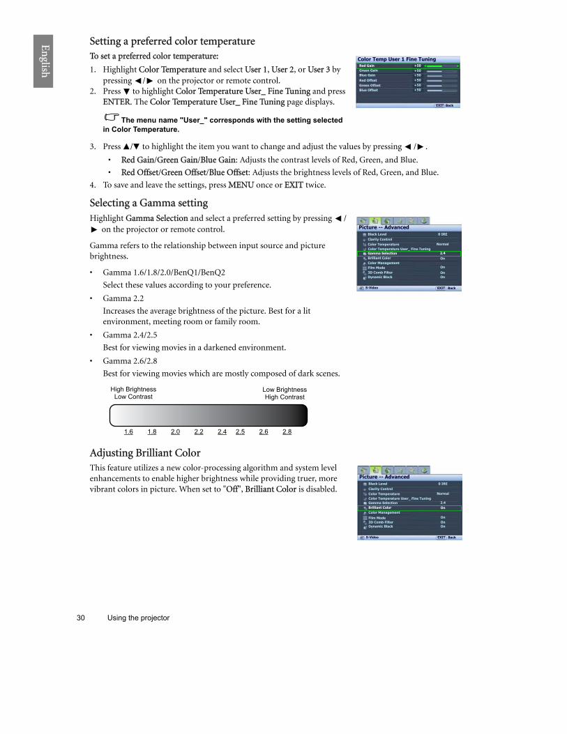
Setting a preferred color temperatureTo set a preferred color temperature:
1. Highlight :olor Temperature and select ;ser 1, ;ser 2, or ;ser 3 by pressing / on the projector or remote control.
2. Press to highlight :olor Temperature ;serD Eine Tuning and press !FT!R. The :olor Temperature ;serD Eine Tuning page displays.
The menu name "User_" corresponds with the setting selected in Color Temperature.
3. Press / to highlight the item you want to change and adjust the values by pressing / .
�• Red Gain/Green Gain/Blue Gain: Adjusts the contrast levels of Red, Green, and Blue.
�• Red Nffset/Green Nffset/Blue Nffset: Adjusts the brightness levels of Red, Green, and Blue.
4. To save and leave the settings, press P!F; once or !QIT twice.
Selecting a Gamma settingHighlight Gamma Selection and select a preferred setting by pressing /
on the projector or remote control.
Gamma refers to the relationship between input source and picture brightness.
�• Gamma 1.6/1.8/2.0/BenQ1/BenQ2
Select these values according to your preference.
�• Gamma 2.2
Increases the average brightness of the picture. Best for a lit environment, meeting room or family room.
�• Gamma 2.4/2.5
Best for viewing movies in a darkened environment.
�• Gamma 2.6/2.8
Best for viewing movies which are mostly composed of dark scenes.
Adjusting Brilliant :olorThis feature utilizes a new color-processing algorithm and system level enhancements to enable higher brightness while providing truer, more vibrant colors in picture. When set to "Nff", Brilliant :olor is disabled.
Color Temp User 1 Fine TuningRed Gain
EXIT Back
Green GainBlue GainRed OffsetGreen OffsetBlue Offset
+50+50+50+50+50+50
Black LevelClarity ControlColor Temperature
Picture -- Advanced
S-Video
0 IRE
EXIT Back
NormalColor Temperature User_ Fine TuningGamma Selection
Color ManagementBrilliant Color
2.4On
Dynamic Black On3D Comb FilterFilm Mode On
On
High BrightnessLow Contrast
Low BrightnessHigh Contrast
1.6 1.8 2.0 2.2 2.4 2.5 2.6 2.8
Black LevelClarity ControlColor Temperature
Picture -- Advanced
S-Video
0 IRE
EXIT Back
NormalColor Temperature User_ Fine TuningGamma Selection
Color ManagementBrilliant Color
2.4On
Dynamic Black On3D Comb FilterFilm Mode On
On

31 Using the projector
!n
glish
Color ManagementIn most installation situations, color management will not be necessary, such as in classroom, meeting room, or lounge room situations where lights remain on, or where building external windows allow daylight into the room.
Only in permanent installations with controlled lighting levels such as boardrooms, lecture theaters, or home theaters, should color management be considered. Color management provides fine color control adjustment to allow for more accurate color reproduction, should you require it.
Proper color management can only be achieved under controlled and reproducible viewing conditions. You will need to use a colorimeter (color light meter), and provide a set of suitable source images to measure color reproduction. These tools are not provided with the projector, however, your projector supplier should be able to provide you with suitable guidance, or even an experienced professional installer.
The Color Management provides six sets (RGBCMY) of colors to be adjusted to favorite colors. When you select each color, you can independently adjust its color range and saturation according to your preference.
To adjust and store the settingsj
1. In the Picture -- Bdvanced menu, highlight Color Management and press !HT!R. The Color Management page displays.
2. Highlight Primary Color and press / to select a color from among Red, Yellow, Green, Cyan, Blue, and Magenta.
3. Press to highlight Range and press / to select the color range you wish to make adjustment. The bigger the range, the more proportions of its two adjacent colors the color contains.
Please refer to the illustration to the right for how the colors relate to each other. For example, if you select Red and set its range at 0, only pure red is selected. Increasing its range will include both the red color close to yellow and red color close to magenta.
Press to highlight Gaturation and adjust the color saturation level by pressing / .
If you select Red and set its range at 0, only the saturation of the pure red will be affected.
Saturation is the amount of that color in a video picture. Lower settings produce less saturated colors; a setting of �“0�” removes that color from the image entirely. If the saturation is too high, that color will be overpowering and unrealistic.
4. To leave and save the settings, press M!HY once or !fIT twice.
Getting Film ModeThis feature helps improve picture quality when projecting video image from a film-sourced DVD.
Black LevelClarity ControlColor Temperature
Picture -- Advanced
S-Video
0 IRE
EXIT Back
NormalColor Temperature User_ Fine TuningGamma Selection
Color Management
2.4
Color ManagementPrimary ColorRangeSaturation
+15+15
Magenta
ENTER
EXIT Back
Brilliant Color On
Dynamic Black On3D Comb FilterFilm Mode On
On
RedYellow Green
CyanMagenta
Blue
Black LevelClarity ControlColor Temperature
Picture -- Advanced
S-Video
0 IRE
EXIT Back
NormalColor Temperature User_ Fine TuningGamma Selection
Color ManagementBrilliant Color
2.4On
Dynamic Black On3D Comb FilterFilm Mode On
On

32 Using the projector
!n
glish
Setting 3D Comb XilterThis feature separates composite signal to Y (brightness) signal and C (color) signal, and can help produce clearer and sharper images with correct colors in place.
This function is only available when a Video signal is selected
Selecting the aspect ratioThe "aspect ratio" is the ratio of the image width to the image height. Digital TV is usually in 16:9 ratio, which is the default for this projector, and most analog TV signals and DVDs are in 4:3 ratio.
With the advent of digital signal processing, digital display devices like this projector can dynamically stretch and scale the image output to a different aspect than that of the image input source. Images can be stretched in a linear manner so the whole of the image is stretched equally, or non-linearly, which distorts the image.
To change the projected picture ratio (no matter what aspect the source is):
I Ysing the remote control
Press one of the aspect ratio keys to suit the format of the video signal and your display requirements.
I Ysing the eSD menu1. Press M!HY and then press / until the Display menu is
highlighted.2. Press to highlight Aspect (atio.3. Press / to select an aspect ratio to suit the format of the video
signal and your display requirements.
About the aspect ratio1. Anamorphic (AHA): Scales an image so that it is displayed in the
center of the screen with a 16:9 aspect ratio. This setting stretches and resizes linearly, except that it treats the vertical and horizontal dimensions independently. It stretches the height of the source image until it reaches the full projected height, and stretches the width of the source image until it reaches the full projected width. This may alter the projected aspect, depending upon the original aspect of the source image. Anamorphic is most suitable for images which are already in a 16:9 aspect, like high definition TV, as it displays them without aspect alteration.
2. 4:3: Scales a picture so that it is displayed in the center of the screen with a 4:3 aspect ratio. This is most suitable for 4:3 pictures like computer monitors, standard definition TV and 4:3 aspect DVD movies, as it displays them without aspect alteration.
Black LevelClarity ControlColor Temperature
Picture -- Advanced
S-Video
0 IRE
EXIT Back
NormalColor Temperature User_ Fine TuningGamma Selection
Color ManagementBrilliant Color
2.4On
Dynamic Black On3D Comb FilterFilm Mode On
On
Aspect RatioKeystonePositionOverscan Adjustment
PIPPC & Component YPbPr Tuning
Display
EXIT Back
0
S-Video
Anamorphic
16:9 picture
4:3 picture

33 Using the projector
!n
glish
3. \etter Tox (\T): Scales a picture to fit the projector�’s native resolution in its horizontal width and resize the picture�’s height to the 3/4 of the projection width. This may produce a picture greater in height than can be displayed, so part of the picture is lost (not displayed) along the top and bottom edges of the projection. This is suitable for the display of movies which are presented in letter box format (with black bars on the top and bottom).
4. Side: Stretches the picture horizontally in a non-linear manner, that is, the edges of the picture are stretched more than the center of the picture to prevent distortion of the central part of the picture. This is suitable for occasions where you want to stretch the width of a 4:3 aspect picture to the width of a 16:9 aspect screen. It does not alter the height. Some widescreen movies have been produced with their width squashed down to the width of a 4:3 aspect, and are best viewed when restretched back to their original width using this setting.
5. (eal: This setting displays the image in a one-to-one pixel mapping without alteration or resize in the center of the projection. This is most suitable for use with PC source inputs.
�• The black portions are inactive areas and the white portions are active areas.
�• OSD menus can be displayed on those unused black areas.
Ysing Panamorph lenses (optional)Panamorph lenses allow you to convert 16:9 projectors to the full 2.35:1 aspect ratio of most motion pictures, showing the best movies without letterbox bars at top and bottom of images while increasing resolution by 33% and brightness by 20%.
You may need a 2.35:1 screen to display the 2.35:1 images. For more information, please go to www.panamorph.com or contact the place you purchased the projector.
16:9 picture
Letter Box format picture
4:3 picture
4:3 picture
2.35:1 aspect ratio image
2.35:1 aspect ratio image using the entire resolution of the 16:9 display
2.35:1 aspect ratio image in a 2.35:1 display area
Pressing LB on the remote
control
Using Panamorph
lens

34 Using the projector
!n
glish
Operating in a high altitude environmentWe recommend that you activate High Altitude Mode when your environment is higher than 1500 meters (around 4920 feet) above sea level, or whenever the projector will be used for extended periods of time (>10 hours) without shutdown.
4o activate High Altitude Modej
1. Press M!HY and then press / until the Advanced Getup menu is highlighted.
2. Press to highlight High Altitude Mode.3. Press / to select On. A confirmation message displays.4. Highlight Ves and press !H4!(.
Operation under High Altitude Mode may cause a higher decibel operating noise level because of increased fan speed necessary to improve overall system cooling and performance.
If you use this projector under other extreme conditions excluding the above, it may display auto shut-down symptoms, which is designed to protect your projector from over-heating. In cases like this, you should switch to High Altitude Mode to solve these symptoms. However, this is not to state that this projector can operate under any and all harsh or extreme conditions.
High Altitude Mode is used when the environment is higher than 1500m.Do you want to turn the High Altitude Mode on?
Yes No
WARNING
Lamp Settings
Baud Rate
High Altitude ModePasswordKey LockReset All Settings
Advanced Setup
EXIT BackS-Video
OnTest Pattern
ISF
HDMI Settings115200

36 Using the projector
!n
glish
Personalihing the projector menu displayThe On-Screen Display (OSD) menus can be set according to your preferences. The following settings do not affect the projection settings, operation, or performance.
�• Rename User Mode: See "Renaming user modes" on page 27 for details.
�• Menu Display Time in the System Setup > Menu Settings menu sets the length of time the OSD will remain active after your last key press. The time length ranges from 5 to 30 seconds in 5-second increments. Use / to select a suitable time length.
�• Menu Position in the System Setup > Menu Settings menu sets the OSD position in five locations. Use / to select a preferred position.
�• \anguage in the System Setup menu sets your familiar language for the On-Screen (OSD) Menus. See "Using the menus" on page 22 for details.
�• Splash Screen in the System Setup menu sets a preferred logo screen to be displayed during projector start-up.
\ocking control keysWith the control keys on the remote control and projector locked, you can prevent your projector settings from being changed accidentally (by children, for example). When Wey \ock is on, no control keys on the remote control and projector will operate except POW!R OH/OXX and !fIT.
To lock the keys:
1. Press M!HU and then press / until the Bdvanced Setup menu is highlighted.
2. Press to highlight Wey \ock, and press !HT!R. The control keys lock.
To unlock the keys, press and hold !fIT on the projector or remote control for 5 seconds.
Turning the projector offTo turn the projector off, press POW!R OXX on the remote control
to turn the projector off directly. Or you can press on the
projector and a warning message appears. Press again.
�• The Power indicator light flashes orange and the fans run for about two minutes to cool the lamp. The projector will not respond to any commands until the cooling process is complete.
�• Then, the Power indicator light is a steady orange once the cooling process has finished and fans stop.
�• If the projector will not be used for an extended period, unplug the power cable from the power outlet.
�• To protect the lamp, the projector will not respond to any commands during the cooling process.
Lamp Settings
Test PatternHigh Altitude ModePasswordKey LockReset All Settings
Advanced Setup
EXIT BackS-Video
ENTER
Off
HDMI Settings
ISF
Baud Rate 115200
Press button again to power off.
Power Off
Press any other button to cancel
II
II

39 Using the projector
!n
glish
Picture -- Basic menu
Picture -- Advanced menu
Function(default setting/value)
Description
Picture Mode(Standard)
Pre-defined picture modes are provided so you can optimize your projector picture set-up to suit your program type. See "Selecting a preset mode" on page 26 for details.
Load Settings FromSelects a preset mode that most suits your need for the picture quality and further fine-tune the picture based on the selections listed below. See "Setting the User 1/User 2/User 3 mode" on page 27 for details.
Brightness(50)
Adjusts the brightness of the picture. See "Adjusting Brightness" on page 28 for details.
Contrast(50)
Adjusts the degree of difference between dark and light in the picture. See "Adjusting Contrast" on page 28 for details.
Color(50)
Adjusts the color saturation level -- the amount of each color in a video picture. See "Adjusting Color" on page 28 for details.
Tint(0)
Adjusts the red and green color tones of the picture. See "Adjusting Tint" on page 28 for details.
Sharpness(depends on the selected input source)
Adjusts the picture to make it look sharper or softer. See "Adjusting Sharpness" on page 28 for details.
Reset Picture Settings
Returns all settings in the Picture -- Basic and Picture -- Advanced menus to the factory preset values. See "Resetting the picture mode" on page 27 for details.
Rename User Mode Renames User 1, User 2, or User 3. See "Renaming user modes" on page 27 for details.
Function (default setting/value)
Description
Black Level(0 IRE)
Sets the picture grayscale as 0 LR! or 7.Q LR!. See "Setting Black Level" on page 29 for details.
Clarity Control Adjusts the picture clarity. See "Controlling image clarity" on page 29 for details.
Color Temperature(depends on the selected Picture Mode)
There are several color temperature settings available. See "Selecting a color temperature*" on page 29 for details.
Color Temperature User_ Fine Tuning See "Setting a preferred color temperature" on page 30 for details.
Gamma Selection(depends on the selected Picture Mode)
See "Selecting a Gamma setting" on page 30 for details.
Brilliant Color(On)
See "Adjusting Brilliant Color" on page 30 for details.
Color Management See "Color Management" on page 31 for details.
Film Mode(On)
See "Setting Film Mode" on page 31 for details.

40 Using the projector
!n
glish
Display menu
System Setup menu
3D Comb Filter(On)
See "Setting 3D Comb Filter" on page 32 for details.
Dynamic Black(On)
Automatically changes the black level of the projected pictures to enhance the effect of contrast ratio.
Function(Default setting/value)
Description
Aspect Ratio(Anamorphic)
There are several options to set the picture�’s aspect ratio depending on your input source. See "Selecting the aspect ratio" on page 32 for details.
Keystone(0)
Corrects any keystoning of the picture. See "Correcting picture distortion" on page 25 for details.
Position(0)
Displays the position adjustment page. To move the projected picture, use the directional arrow keys. The values shown on the lower position of the page change with every key press you made until they reach their maximum or minimum.
This function is only available when the Component 1, Component 2, or PC signal is selected.
Overscan Adjustment(depends on the selected input source)
Conceals the poor picture quality in the four edges. You can also manually press / to decide how much to be concealed. Setting 0 means the picture is 100%
displayed. The greater the value, the more portion of the picture is concealed while the screen remains filled and geometrically accurate.
PIP Turns the PIP window on or off and makes related adjustments. See "Displaying more than one image source simultaneously" on page 35 for details.
PC & Component YPbPr Tuning
a.Size (0)Adjusts the horizontal width of the picture.Phase (0)Adjusts the clock phase to reduce picture distortion.AutoAdjusts the phase, and frequency automatically
These functions are only available when the Component 1, Component 2, or PC signal is selected.
Function(Default setting/value)
Description
Language( )
Sets the language for the On-Screen Display (OSD) menus. See "Using the menus" on page 22 for details.
Splash Screen(BenQ logo)
Allows you to select which logo screen will display during projector start-up. You can choose TenU logo screen, Tlue screen or Tlack screen.
Projector Position(Floor Front)
The projector can be installed on a ceiling or behind a screen, or with one or more mirrors. See "Choosing a location" on page 12 for details.
Auto Off(Disable)
Prevents unnecessary projection when no signal is detected for a long time. See "Setting Auto Off " on page 44 for details.
Sleep Timer(Disable)
Sets the auto-shutdown timer. The timer can be set to a value between 30 minutes and 3 hours.
41 Using the projector
!n
glish
Advanced Setup menu
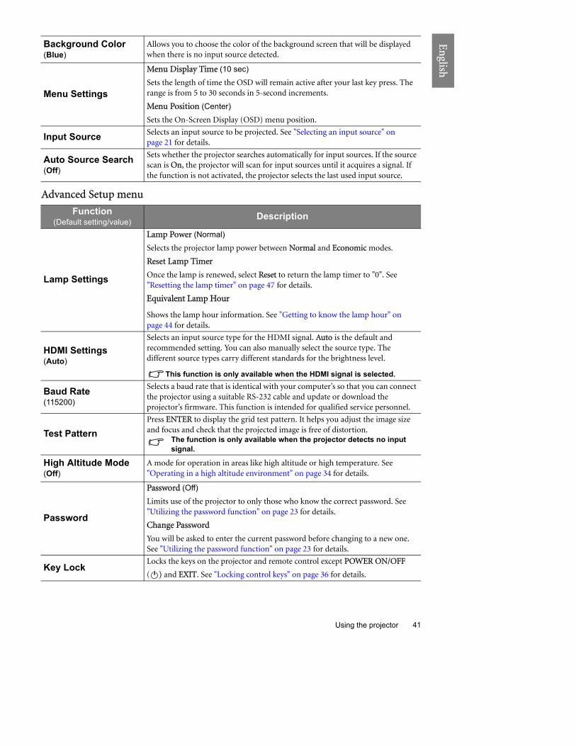
Background Color(Blue)
Allows you to choose the color of the background screen that will be displayed when there is no input source detected.
Menu Settings
Menu Display Time (10 sec)
Sets the length of time the OSD will remain active after your last key press. The range is from 5 to 30 seconds in 5-second increments.
Menu Position (Center)
Sets the On-Screen Display (OSD) menu position.
Input Source Selects an input source to be projected. See "Selecting an input source" on page 21 for details.
Auto Source Search(Off)
Sets whether the projector searches automatically for input sources. If the source scan is On, the projector will scan for input sources until it acquires a signal. If the function is not activated, the projector selects the last used input source.
Function(Default setting/value)
Description
Lamp Settings
Lamp Power (Normal)
Selects the projector lamp power between Hormal and !conomic modes.
Reset Lamp Timer
Once the lamp is renewed, select Reset to return the lamp timer to "0". See "Resetting the lamp timer" on page 47 for details.
!quivalent Lamp Hour
Shows the lamp hour information. See "Getting to know the lamp hour" on page 44 for details.
HDMI Settings(Auto)
Selects an input source type for the HDMI signal. Auto is the default and recommended setting. You can also manually select the source type. The different source types carry different standards for the brightness level.
This function is only available when the HDMI signal is selected.
Baud Rate(115200)
Selects a baud rate that is identical with your computer�’s so that you can connect the projector using a suitable RS-232 cable and update or download the projector�’s firmware. This function is intended for qualified service personnel.
Test PatternPress !HT!R to display the grid test pattern. It helps you adjust the image size and focus and check that the projected image is free of distortion.
The function is only available when the projector detects no input signal.
High Altitude Mode(Off)
A mode for operation in areas like high altitude or high temperature. See "Operating in a high altitude environment" on page 34 for details.
Password
Password (Off)
Limits use of the projector to only those who know the correct password. See "Utilizing the password function" on page 23 for details.
Rhange Password
You will be asked to enter the current password before changing to a new one. See "Utilizing the password function" on page 23 for details.
Key LockLocks the keys on the projector and remote control except POS!R OHbOXX
( ) and !fIT. See "Locking control keys" on page 36 for details.II

42 Using the projector
!n
glish
Information menuThis menu shows you the current operating status of the projector.
Some picture adjustments are available only when certain input sources are in use. Unavailable adjustments are not shown on the screen.
Reset All Settings
Returns all settings to the factory preset values.
The following settings will still remain: names of user modes, Keystone, Language, Projector Position, High Altitude Mode, Password, Key Lock, and ISF.
ISF
The ISF calibration menu is password protected and only accessible by authorized ISF calibrators. The ISF (Imaging Science Foundation) has developed carefully crafted, industry-recognized standards for optimal video performance and has implemented a training program for technicians and installers to use these standards to obtain optimal picture quality from BenQ video display devices. Accordingly, we recommend that setup and calibration be performed by an ISF certified installation technician.
For more information, please go to www.imagingscience.com or contact the place you purchased the projector.
Function DescriptionSource Shows the current signal source.
Picture Mode Shows the selected mode in the Cicture -- Basic k Cicture Mode menu.
Resolution Shows the native resolution of the input source.
Equivalent Lamp Hour Shows the total lamp time used.
Firmware Version Shows the firmware version of your projector.

43 Additional information
!n
glish
Additional informationCare of the projectorYour projector needs little maintenance. The only thing you have to do on a regular basis is keep the lens clean. Never remove any parts of the projector except the lamp. Contact your dealer or local customer service center if the projector fails to operate as expected.
Cleaning the lensClean the lens whenever you notice dirt or dust on the surface. Before you attempt to clean the lens, turn the projector off, unplug the power cable, and leave it several minutes to cool completely.
1. Use a canister of compressed air to remove dust. (Available from building hardware or photographic suppliers.)
2. If there is stubborn dirt or smudge marks, use a proper photographic lens brush or moisten a clean soft lens cloth with lens cleaner to gently wipe the lens surface.
3. Never use any type of abrasive pad, alkaline/acid cleaner, scouring powder, or volatile solvent, such as alcohol, benzene, thinner or insecticide. Using such materials or maintaining prolonged contact with rubber or vinyl materials may result in damage to the projector surface and cabinet material.
Never touch the lens with your finger or rub the lens with abrasive materials. Even paper towels can damage the lens coating. Only ever use a proper photographic lens brush, cloth, and cleaning solution. Do not attempt to clean the lens while the projector is switched on or is still hot from previous use.
Cleaning the projector caseBefore you attempt to clean the case, turn the projector off, unplug the power cable, and leave it several minutes to cool completely.
1. To remove dirt or dust, wipe the case with a soft, dry, lint-free cloth.2. To remove stubborn dirt or stains, moisten a soft cloth with water and a neutral detergent. Then wipe
the case.
Never use wax, alcohol, benzene, thinner or other chemical detergents. These can damage the case.
Storing the projectorIf you need to store the projector for an extended time, please:
1. Make sure the temperature and humidity of the storage area are within the recommended range for the projector. Please refer to the Spec. page in this manual or consult your dealer about the range.
2. Retract the adjuster feet.3. Remove the batteries from the remote control.4. Pack the projector in its original packing or equivalent.
Transporting the projectorIt is recommended that you ship the projector with its original packing or equivalent.

44 Additional information
En
glish
\amp informationcetting to know the lamp hourWhen the projector is in operation, the duration (in hours) of lamp usage is automatically calculated by the built-in timer. The method of calculating the equivalent lamp hour is as follows:
Equivalent lamp hour = 1 (hours used in Economic mode) + 3/2 (hours used in Hormal mode)
See "Setting Lamp Power as Economic" below for more information on Economic mode.
To obtain the lamp hour information:
1. Press MEHU and then press / until the Bdvanced Setup menu is highlighted.
2. Press to highlight \amp Settings and press EHTE(. The \amp Settings page displays.
3. The lamp hour information is shown in the row of Equivalent \amp aour.
4. To leave the menu, press MEHU.
Extending lamp lifeThe projection lamp is a consumable item that normally can last up to 2000-3000 hours with proper usage. To keep the lamp life as long as possible, you can do the following settings via the OSD menu.
I Setting \amp Power as Economic
Using Economic mode reduces system noise and power consumption. If the Economic mode is selected, the light output will be reduced and result in darker projected pictures.
Setting the projector in Economic mode also extends the lamp life. To set Economic mode, go to the Bdvanced Setup > \amp Settings > \amp Power menu and press / .
I Setting Buto Off
This function allows the projector to turn off automatically if no input source is detected after a set period of time.
To set Buto Off, go to the System Setup > Buto Off menu and press / to select a time period. The time period can be set from 5 to 30 minutes in 5-minute increments. If the preset time lengths are not suitable for your presentation, select Disable. The projector will not automatically shut down in a certain time period.
Lamp Settings
Test PatternHigh Altitude ModePasswordKey LockReset All Settings
Advanced Setup
EXIT BackS-Video
ENTER
Off
Lamp SettingsLamp Power
Equivalent Lamp Hour
EXIT Back
Reset Lamp TimerEconomic
HDMI Settings
ISF
Baud Rate 115200
50 hours
LanguageSplash ScreenProjector PositionAuto OffSleep Timer
Background ColorMenu SettingsInput Source
System Setup
S-Video
EnglishBenQ
Auto Source Search
EXIT Back
DisableDisable
Blue
On
Floor Front

45 Additional information
!n
glish
Timing of replacing the lampWhen the Lamp indicator lights up red or a message appears suggesting it is time to replace the lamp, please install a new lamp or consult your dealer. An old lamp may cause a malfunction in the projector and in some instances the lamp may explode. Go to http://lamp.BenQ.com for a replacement lamp.
The Lamp indicator light and Temperature warning light will light up if the lamp becomes too hot. Turn the power off and let the projector cool for 45 minutes. If the Lamp or Temp indicator still lights up after turning the power back on, please contact your dealer. See "Indicators" on page 48 for details.
The following Lamp warning displays will remind you to change the lamp.
(eplacing the lamp�• To reduce the risk of electrical shock, always turn the projector off and disconnect the power cable
before changing the lamp.�• To reduce the risk of severe burns, allow the projector to cool for at least 45 minutes before replacing
the lamp.�• To reduce the risk of injuries to fingers and damage to internal components, use caution when
removing lamp glass that has shattered into sharp pieces.�• To reduce the risk of injuries to fingers and/or compromising image quality by touching the lens, do
not touch the empty lamp compartment when the lamp is removed.�• This lamp contains mercury. Consult your local hazardous waste regulations to dispose of this lamp in
a proper manner.
Status MessageThe lamp has been in operation for 2000 hours. Install a new lamp for optimal performance. If the projector is normally run with !conomic selected (See "Getting to know the lamp hour" on page 44), you may continue to operate the projector until the 2980 hour lamp warning appears.
Press !HT!( to dismiss the message.
The lamp has been in operation for 2980 hours. It is strongly recommended that you replace the lamp at this age. The lamp is a consumable item. The lamp brightness diminishes with use. This is normal lamp behavior. You can replace the lamp whenever you notice that the brightness level has significantly diminished. If the lamp is not replaced beforehand, it should be replaced after 2980 hours usage.
Press !HT!( to dismiss the message.
The lamp has been in operation for 3000 hours. The lamp MUST be replaced before the projector will operate normally.
Press !HT!( to dismiss the message.
OK
NOTICE: Order replacement lamp
Lamp > 2000hrs
Order a new lamp at lamp.benq.com
WARNING
OK
NOTICE: Replace lamp soon
Lamp > 2980hrs
Order a new lamp at lamp.benq.com
WARNING
NOTICE: Replace lamp nowLamp > 3000hrs
Lamp-usage time exceededReplace lamp (refer to User�’s Manual)then reset lamp timer.Order a new lamp at lamp.benq.com
OK
WARNING

46 Additional information
En
glish
1. Turn the power off and disconnect the projector from the power outlet. Turn off all connected equipment and disconnect all other cables. See "Turning the projector off " on page 36 for details.
2. Slightly lift the projector up. Loosen the screws on the lamp cover (located on the left side).
3. Remove the lamp cover.
4. Loosen the screws that hold the lamp to the projector. If the screws are not loosened completely, they could injure your fingers.
5. Lift the handle so that it is perpendicular to the lamp. Use the handle to slowly pull the lamp out of the projector.
Notes
�• Pulling it too quickly may cause the lamp to break and scatter broken glass in the projector. To reduce the risk of injuries to fingers and damage to internal components, use caution when removing lamp glass that has shattered.
�• Do not place the lamp in locations where water might splash on it, children can reach it, near or above heat sources, or near flammable materials.
�• Do not insert your hand into the projector when the lamp is removed. If you touch the optical components inside, it could cause blurred images.
6. Insert the replacement lamp. Make sure it is pushed fully and firmly in place.
7. Tighten the screws securing the lamp box.
8. Ensure the handle is fully locked in place.
Notes
�• Please be careful to not over-tighten the screws.
�• Loose screws may cause a bad connection, which could result in malfunction.
9. Re-install the lamp cover.
10. Tighten the screws on the lamp cover.
11. Reapply power and turn the projector back on.

47 Additional information
!n
glish
(esetting the lamp timerDo not reset the lamp timer if the lamp has not been replaced as this could cause damage.
1. After the start-up logo, press M!HY and then press / until the Ad7an.ed Getup menu is highlighted.
2. Press to highlight \amp Gettings and press !HT!(. The \amp Gettings page displays.
3. Highlight (eset \amp Timer and press !HT!(. A warning message displays asking if you want to reset the lamp timer. Highlight (eset and press !HT!(. The lamp time will be reset to "0".
Lamp SettingsHDMI Settings
High Altitude ModePasswordKey LockReset All Settings
Advanced Setup
EXIT BackS-Video
ENTER
Off
Lamp SettingsLamp Power
Equivalent Lamp HourENTER
EXIT Back
Reset Lamp Timer
Reset Lamp Timer?
Reset Cancel
WARNING
Normal
Test Pattern
ISF
Baud Rate 115200

48 Additional information
!n
glish
IndicatorsThere are three indicators which show the status of the projector. Check the following for information about the indicator lights. If there is anything wrong, turn the projector off and contact your dealer.
>hen the projector is in a normal state
>hen the projector is in an abnormal state
Power Temp Lamp Status & DescriptionOrange Off Off Stand-by mode
GreenFlashing Off Off Powering up
Green Off Off Normal operation
OrangeFlashing Off Off
�• The projector needs 90 seconds to cool down as it was abnormally shut down without the normal cooling down process.
�• The projector needs to cool for 90 seconds after the power is turned off.
Power Temp Lamp Status & Description
Off Off Red �• The lamp has been damaged. Please contact your local BenQ customer center for purchasing a new lamp.
Orange Off Red�• The lamp is not properly attached.
�• The lamp has been damaged. Please contact your local BenQ customer center for purchasing a new lamp.
Off Red Off
The fans are not working.
The projector has shut down automatically. If you try to re-start the projector, it will shut down again. Please contact your dealer for assistance.
Off Red Red
Off Red Green
Off Red Orange
Off Green Red Fan sensors errorFans do not rotate during powering up.
Off Green Orange
Off Orange Red
Red Red Red
Thermal condition error
Red Red Green
Red Red Orange
Green Red Red
Green Red Green
Green Red Orange
Orange Red Red The internal temperature is too high.
�• The intake ventilation or the exhaust ventilation is blocked.
�• The projector may be in a poorly ventilated location.
�• The ambient temperature may be too high.
Orange Red Green
Orange Red Orange

49 Additional information
!n
glish
TroubleshootingProblem Cause Remedy
The projector does not turn on.
There is no power from the power cable.
Plug the power cable into the AC inlet on the rear of the projector, and plug the power cable into to the power outlet. If the power outlet has a switch, make sure that it is switched on. (See page 20.)
Attempting to turn the projector on again during the cooling process.
Wait until the cooling down process has completed.
The lamp cover is not securely attached.
Correctly attach the lamp cover. (See page 45.)
No picture.
The video source is not turned on or connected correctly.
Turn the video source on and check that the signal cable is connected correctly. (See page 17.)
The projector is not correctly connected to the input source device.
Check the connection. (See page 17.)
The input source has not been correctly selected.
Select the correct input source with the Source keys on the remote control or SeYRC! on the projector. (See page 21.)
Image is unstable.The connection cables are not securely connected to the projector or the signal source.
Correctly connect the cables to the appropriate terminals. (See page 17.)
Picture is blurred.
The projection lens is not correctly focused.
Adjust the focus of the lens using the focus ring. (See page 21.)
The projector and the screen are not aligned properly.
Adjust the projection angle and direction as well as the height of this projector if necessary. (See page 25.)
Remote control does not work correctly.
The batteries are out of power.Replace both of the batteries with new ones. (See page 7.)
There is an obstacle between the remote control and the projector.
Remove the obstacle. (See page 7.)
You are too far away from the projector.
Stand within 8 meters (26.2 feet) of the projector. (See page 7.)

50 Additional information
En
glish
SpecificationsAll specifications are subject to change without notice.
epticalProNection system Single-chip DLPTM system.DMD chip 0.65" DLP (1920 x 1080)Lens F = 2.48 to 2.83, f = 24.1 to 36.14 mmProNection screen size 28" to 300"Lamp 280W
ElectricalCompatibility PC: 640 x 400 to 1920 x 1200
Video: NTSC, PAL, SECAM, YPbPr (480i/480p/576i/576p), HDTV (720p/1080i/1080p)
DDC 2BColor Space Typ. = 70% NTSC (Target Color Gamut = HDTV Rec. 709)
TerminalsInput Analog RGB: D-Sub 15-pin (female) x 1
HDMI (V. 1.3) x 2
Component Video (Y/CB/CR, Y/PB/PR) x 1
Component Video (Y/CB/CR, Y/PB/PR) x 1 (shared with RGB input)
Composite Video x 1
S-Video x 1eutput
Control
12VDC (Max. 0.5 A)
Serial Connector: RS232 9 pin (male)
Mini B type USB x 1
IR receiver x 2
General characteristicsProNector weight 6.7 kg (14.8 lbs)Power VAC 100-240V, 3.9A, 50-60Hz (Automatic)Power consumption Max. 430W; Standby < 1 Weperating temperature 0 °C to 35 °C at sea leveleperating humidity 10% - 90% (without condensation)eperating altitude 0-1499 m at 0°C-35°C
1500-3000 m at 23°C-30°C (with High Altitude Mode on)Storage temperature -20°C- 60°C/-4°F to 140°FStorage humidity 10% - 90%

51 Additional information
!"
#$%&'
D%m)"&%+"&428 mm x 317 mm x 145 mm (W x D x H)
R)%$%"# m+9", %"&,1$$1,%+"
428
317 145
178.98
221.98239.89492
502.87395.4362.4
422.49
284
225
235
101.49
Ceiling mount screws:M4 x 8 (Max. L = 8 mm)
Unit: mm

Appendix VI - Conveyor Belt Owner’s Manual

Read instructions for unpacking your conveyor on the inside the front cover of this manual.
Read assembly and safety instructions before using.
MINI-MOVER LP
MINI-MOVERProduct Group: TCMM-LP LOW-PROFILE (LP) SERIES
OWNER’S MANUAL
Operating and Safety Instructions
Whipple Enterprises, Inc.Whipple Enterprises, Inc.
Visit us on the Web at www.mini-mover.com
S T O P
© 2008-10 Whipple Enterprises. All rights reserved LP-2009-1201
Revision No: LP-2009-1201
Visit us on the Web at www.mini-mover.com
Please read this instruction manual.
Congratulations, you have purchased a high quality Mini-Mover Low-Profile (LP) Series conveyor. Please read this manual thoroughly before you unpack and install your conveyor. We suggest that you keep the manual and enclosed warranty information for future refer-ence.
Unpacking Your Conveyor.
1. Open both ends of the carton. 2. Do not tip carton on end. 3. Remove foam packing material from both ends of the carton. 4. Locate the drive end (has 1/2” drive shaft or drive belt pulley).
5. Grasp the drive shaft and conveyor siderail and pull the conveyor from the carton. 6. The conveyor is completely assembled and ready for installation. It may be advisable to install the drive package to the module prior to installation. We suggest that you retain the carton and packing material in the event the conveyor must be returned for service.
Important Information
Mailing and Shipping Address:
Whipple Enterprises, Inc.
21150 Shake Ridge Rd. Volcano, CA 95689
Customer Service:
Phone: 866-380-5128
Fax: 866-900-5124
Email: [email protected]
Before calling Customer Service, please have your model and serial number available.
For Your Reference:
Model Number _______________________________ Factory Drive Package _______________________________
Serial Number _______________________________
In-service date _________ / _________ / __________

Whipple Enterprises, Inc.LP Series Conveyor Limited Lifetime Warranty
Warranty Service Provided Whipple Enterprises warrants its Mini-Mover LP Series Conveyors against defects in material or workmanship for the usable lifetime of the product following the origi-nal date of purchase. Whipple Enterprises’ responsibility under this warranty is lim-ited to the repairing or replacing, at its sole option, any defective product. The war-ranty begins on the date of the original purchase from the factory for its usable life-time and is not transferrable to any third parties. This lifetime warranty is voided once the original purchaser sells or rents the unit, the unit has been significantly abused or has been used for purposes beyond the intended parameters of conveyor design and operation. However, in cases where ownership of the unit should trans-fer to a third party, that party may contact Whipple Enterprises for consideration of possible transfer of this warranty, on a case-by-case basis.
WHIPPLE ENTERPRISES MAKES NO OTHER WARRANTY. WHIPPLE ENTERPRISES SPECIFICALLY DISCLAIMS ANY IMPLIED WAR-RANTIES, INCLUDING WARRANTIES OF MERCHANTABILITY AND FITNESS FOR ANY PARTICULAR PURPOSE. IN NO EVENT SHALL WHIPPLE ENTER-PRISES BE LIABLE FOR DIRECT, INDIRECT, SPECIAL OR CONSEQUENTIAL DAMAGES.
Warranty Service Not Provided This warranty does not cover normal wear and tear of parts as a result
of normal operation over time, nor damage resulting from accident, misuse, abuse, improper installation, unauthorized modification and/or loss of parts. This warranty is voided if any unauthorized person opens, alters, or repairs the unit beyond that which is directed in this manual.
Obtaining Service under WarrantyYou must obtain a Return Goods Authorization (RGA) number from
Whipple Enterprises’ customer service. The product must be returned to Whipple Enterprises with transportation charges prepaid and must be accompanied by a brief description of the problem encountered and proof of purchase.
Product Return PolicyThe Return Goods Authorization (RGA) number is required for return of
any product to Whipple Enterprises. This number must be clearly visible on the packing carton.
Please retain the original shipping carton and packing materials. The origi-nal shipping carton is the best shipping container for returning your unit, if required.
12 1
Table of Contents Warranty & Service
Safety Instructions Installation & Operating Instructions Specifications LP Components & Description Cleaning & Maintenance Belt Tensioning Procedure Belt Tracking Procedure Warranty & Service Information
Page
2
4
5
6
8
10
11
12
Belt Tracking Adjustment
Mini-Mover conveyors utilize precision crowned pulleys for superior belt tracking. Belt tension and tracking are initially set at the factory prior to shipment. Over time, belt tracking may require adjustment in the field. The procedure for adjusting the belt tracking using the belt tension tool is as follows:
1. Perform “Belt Tensioning Procedure,” steps 1 through 7, on Pg.10.
2. Start the conveyor and run the belt without load for 30 sec-
onds. While facing the idler (non-motor) end of the conveyor, observe the belt tracking position. Should the belt be center tracking, proceed to Step 4 below. Should the belt be track-ing to either side, tighten the belt tension lock screw on the side opposite to which the belt is tracking.
3. To adjust the belt tracking, tighten (clockwise) the tensioning
tool knurled adjustment knob in about 1/16-turn increments until the belt is center tracking. Run the conveyor an addi-tional 1-2 minutes to assure the belt continues to center track. Make any final adjustments required.
4. Using a 3/16’’ short handle hex wrench, tighten the belt ten-
sion lock screw until the wrench handle flexes approximately ½.”
5. Remove the tension tool by loosening the adjustment knob.
The conveyor is ready to return to service.
Parts & Service
866-380-5128
2 11
Cleaning & Maintenance Safety Instructions
IMPORTANT SAFETY INSTRUCTIONS
To reduce the risk of fire, electrical shock and injury, always follow these basic safety precautions when using your conveyor.
1. Read and follow all instructions.
2. Follow all warnings and instructions marked on your conveyor.
3. Connect the conveyor to a properly grounded power source. Operating the conveyor beyond the specified voltage or fre-quency range will void the TCMM-LP warranty. Check with a qualified electrician if you are not sure if the power source is grounded properly.
4. Do not overload power source or use extension cords. This can increase the risk of fire or electrical shock.
5. Do not allow anything to rest on the power cord. Do not install the conveyor where people will walk on the power cord.
6. Disconnect the conveyor from the power source before cleaning, belt adjustment or maintenance. Do not use liquidor aerosol cleaners. When necessary, clean using a soft cloth moistened with a mild detergent solution.
7. Do not locate the conveyor in areas where water or other fluids may splash on the motor or electrical control box.
8. Do not place the conveyor on an unstable cart, stand, or table. A fall could cause serious damage to the worker and/or conveyor.

9. The conveyor gearmotor is air cooled. The gearmotor should not be placed in a built-in enclosure unless proper ventilation is provided.
10. Do not operate the conveyor during an electrical storm. If your area gets frequent thunder storms, we strongly recommend connecting your conveyor into a power surge protector.
11. Disconnect the conveyor from the power source and consult a qualified service representative in any of the following situations.
A. When the power supply cord is frayed or damaged.
B. If liquid is spilled on the motor housing or electrical control
box. C. If the conveyor does not operate normally when following
the basic operating instructions. D. If the conveyor has been dropped or the motor, gearhead,
or electrical control box is damaged. 12. Keep all loose clothing away from conveyor belt. 13. Due to the variety of drive types, drive positioning & belt configurations,
point-of-installation guarding is the responsibility of the end user.
SAVE THESE INSTRUCTIONS.
For assistance, call Parts & Service
866-380-5128
10
Safety Instructions Cleaning & Maintenance
3
Reassembly (continued):
5. Install the T-slot extrusion (if supplied). 6. Follow adjusting the belt tensioning procedure below.
Belt Tensioning Procedure: (for both 1- and 2-knob tensioning tools)
1. Position the conveyor to easily access both sides of the idler end (opposite the gearmotor end).
2. Install the belt tensioning tool with hook connector over the belt tension lock screw washers. (See arrows, figs. 4 & 5)
3. Turn the knurled adjustment knob(s) on the tensioning tool clockwise until the tensioning cross brace is against the conveyor siderail ends. On the 2-knob tensioning tool, alternately turn the knobs on either side in ½-turn increments to maintain equal distance between fixed and tensioning cross-braces. (figs. 4 & 5)
4. Using a 3/16” hex key loosen both the belt tension lock screws. On the 2-knob tensioning tool, to assure no side-loading during tensioning op-eration, use a rule to measure distance at two points between fixed and tensioning braces, and adjust knob as needed to align braces.
5. To tension belt: 1-knob version -- Tighten (clockwise) the tensioning tool knurled adjustment knob in ½- turn increments until hand tight. 2-knob version -- Tension via alternately turning knobs ½ turn until belt is ten-sioned; to assure proper pulley alignment, measure with a rule as in Step 4 above. CAUTION: Do not over-tension belt. Hand-tighten the adjustment knobs. Use only that force which can be applied by thumb and forefinger on the tensioning tool adjustment knob.
6. Using the 3/16” hex key, tighten both tension belt adjustment screws until wrench handle flexes approx. ½.”
7. Proceed to Pg. 11 for “Belt Tracking Adjustment.”
Fig. 4 Fig. 51-knob tensioning tool (for belts ≤ 10” wide) 2-knob tensioning tool (for belts 12” or wider)
HookHook
4 9
Cleaning & Maintenance
Installation & Operating Instructions
Fig. 3 - Bearing Alignment Pin Position
Belt Replacement:
1. Follow the procedure on Pg. 8 to remove the blank siderail. 2. Slide the old belt off the pulleys and discard. 3. Slide the new belt over the pulleys and follow the
reassembly procedure below. Reassembly:
1. Position the belt on the pulleys at both ends of the con- veyor, then:
2. Position the blank siderail to align the side rail to bedplate
screw holes, and the bearing adaptors to the pulley bearings 3. Insert and hand tighten the side rail to bedplate screws. 4. Using a 1/8” short handle hex wrench, tighten the siderail screws until the wrench handle flexes approximately ½.”
Cleaning, continued: (Polyurethane belts only) When the detergent and water solution method is unsuccessful:
Occasional Cleaning: Use “409” or equivalent solution. Wet surfaces using a moistened cloth. Let stand for 10 minutes, scrub with cloth, and rinse with water-moistened cloth.
Infrequent Cleaning: Consult factory for recommended cleaning solvents.
Read all Safety Instructions given on pgs. 2 and 3 before perform-ing the following installation or operation procedures on your con-veyor.
Installation:
1. Your conveyor may be located on any stable surface, mounted to stand, sur-face or machine mounting brackets or other sturdy fabricated bracket.
2. The conveyor should not be located in an area where the gearmotor or electri-cal control box would be exposed to water or other liquids.
3. The gearmotor should not be located in an enclosure unless proper ventilation is provided.
4. Connect the conveyor to a properly grounded electrical power source that con-forms to the voltage and frequency specifications listed on the Pg. 5.
5. The conveyor may be oriented in any position from vertical to horizontal. 6. Consideration should be given to installations that restrict access to removal of
the siderail opposite the gearmotor (blank side, per Fig. 2a on Pg. 6) for clean-ing or if belt replacement is required.
Operation:
1. Your conveyor module is ready, in most cases, for installation out of the carton. If your particular unit is equipped with a factory-supplied drive package or other options, the applicable installation instructions will accompany the shipment.
2. The belt has already been tensioned at the factory. 3. If a factory drive package is supplied, the default wiring configuration of the
gearmotor will provide belt movement in the direction of the gearmotor. 4. Certain wiring configurations are not pre-wired to motor controls; this will re-
quire wiring and provision of controls to be performed by the user. Reversing the Direction of the Belt Travel:
Fixed-Speed Factory Drive Package 1. Disconnect the power source. 2. Wait 2 minutes, then open the electrical control box to access wiring. 3. Swap wires or connectors per the wiring diagram located inside of the control
box cover; a general diagram also appears as Fig. 1 on pg. 5. 4. Replace the electrical control box cover before reconnecting the to the power
source. Variable-Speed Factory Drive Package 1. Bring the gearmotor to a complete stop via Run/Stop switch. 2. Slide the Rotation switch to the desired position (i.e., clockwise/CW or counter-
clockwise/CCW). Refer also to Fig. 2c, #12 on pg. 6.
Siderail Pin Position, Idler Pulley Bearing

Utilizing a rugged aluminum frame, sealed bearings, and reinforced end-less belting, MINI-MOVER LP series conveyors are designed for years of trouble free service. To maximize belt life and reduce the risk of dam-aging the bed plate and side rail surfaces, removal of debris and clean-ing the conveyor belt on a regular basis is recommended. Procedures for cleaning, belt replacement, and adjusting the belt tension follow:
Removing the Blank Siderail:(See figs, 2a & 2b on Pg. 6)
1. Disconnect the conveyor drive from the electrical power source.
2. Remove the unit from the stand or other mounting, and place it on a flat, stable surface.
3. Locate the belt tension lock screws (see figs. 2a and 2b, #1) and loosen -- do not remove -- using a 3/16” hex wrench.
4. Turn the unit on its side with the gearmotor down. 5. Using a 1/8” hex key, remove T-slot (if equipped), then remove the Maintenance Access Screws (Fig. 2a, #3). 6. Lift the siderail straight up to access the belt and bed-
plate, and set aside.
Cleaning:1. Follow the procedure above to remove the blank side- rail.
2. Slide the belt off both pulleys and set aside. 3. Using a brush (do not use a wire brush) or cloth, remove
any debris or other bulk material from the inside surface of the gearmotor siderail and all surfaces of the blank siderail.
4. Using a mild solution of detergent and warm (not hot) water-moistened cloth, clean all surfaces of both side-rails, bedplate and belt.
Caution: Do not allow liquid to enter the motor housing.
8
Specifications Cleaning & Maintenance
5
CONVEYOR MODULE (Standard Construction)
Siderails: 0.25” hard black anodized aluminum Bedplate: 0.37” aluminum Drive Pulley: 1.25” dia. precision knurled solid aluminum Idle Pulley: 1.25” dia. precision crowned solid aluminum DRIVE PACKAGE � No Drive Package Supplied by Factory
Gearmotor:
Power Output Power Source Continuous Rating (Input Voltage/Frequency/Phase)
� 1/30 HP, 25W � 115/60/1 � 1/18 HP, 40W � 230/50-60/1 � 1/8 HP, 90W � 230/60/3 � Other: � Other: ________________________ ________________________
Gearhead: (Parallel Shaft) Gear Ratio: Gearhead Speed: RPM Belt Speed: FPM Torque: LB-IN
Drive Mounting: � LEFT � OVERMOUNT ________ degrees � RIGHT � SIDE MOUNT
Style _____________ � REMOTE � UNDERMOUNT ________ degrees
CONVEYOR BELTING � No belt supplied by Factory � Urethane � PVC � Other ________________________
MOTOR MOTOR
STANDARD DIRECTION REVERSE DIRECTION
2-PRONG CAPACITOR
4-PRONG CAPACITOR: MOVE THE CONNECTOR WITH 2 WIRES TO VACANT PRONG
Fig. 1 — Control Box Wiring Diagram
Figs. 2a and 2b (to the left) provide location of conveyor drive shaft, maintenance access screws, belt adjustment points and mounting holes. The following lists their description and func-tion. Fig. 2c (bottom left) shows the controls located on the factory-supplied controller for those units equipped with the Variable-Speed option.
1. Belt Tension Lock Screws. Locks idler pulley in position after belt tensioning or tracking adjustment is completed (One located on either side of pulley)
1a. Pulley Bearing Positioning Pin. Locks position to prevent bearing adapter rotation (One located on either side of pul-ley)
2. T-Slot Extrusion. Facilitates mounting of guide rails, sensors and other accessories (optional)
3. Maintenance Access Screws. Attaches frame siderail to bed- plate. 1/4-20 low head screws are located behind the optional T-slot extrusion. Quantity per conveyor is length-specific
4. T-Slot Mount Screws. 10-32 flat head fasteners that attach optional T-slot extrusion to frame side rail. Quantity per con-veyor is length-specific
5. Universal Drive Shaft. Drives conveyor. ½” diameter by 5/8’’ length left, right or both sides, depending on customer specifica-tions
6. Tapped 10-32 Holes. Conveyor mounting holes. Tapped 10-32 to accept optional mounting bracket accessory or stands
7. Frame Siderails. Precision-machined aluminum. Part of con- veyor frame
8. Bedplate. Polished aluminum slider bed under belt
9. Indicator Light. Visual indication of conveyor power or fault status; refer to your controller manual for details
10. Speed Control Switch. Rotary actuated control of belt speed
11. Run/Stop Switch. Controls belt movement
12. Rotation Switch. Acts to reverse direction of belt movement
13. Power Cord w/ Strain Relief. 115/60/1 VAC, 7 ft. length
6 7
LP Components — Description LP Components
Fig. 2a — Conveyor Siderail (blank side)
Fig. 2b — Conveyor Side View
13
9
10
11
12
Fig. 2c — Variable-Speed Control Unit
4 5
6
1a 2 3 1
1
7
2
5
8
1a


OUT

OUT

IN
cabl
es

IN
mot
or

Appendix VII - Installations shots


![RLH [ ] RLHantimodular.com/.../TheRedQueen_2013.pdf · [ ]RLH Pulse Room, Rafael Lozano-Hemmer The Red Queen, exhibition catalogue, 18 June, 2013-21 April, 2014, Museum of Old and](https://static.fdocuments.in/doc/165x107/5f0e79e67e708231d43f6e86/rlh-rlh-pulse-room-rafael-lozano-hemmer-the-red-queen-exhibition-catalogue.jpg)