PLDM for BIOS Control and Configuration - Home | … Platform Level Data Model (PLDM) for BIOS...
56
1 2 3 4 5 6 7 8 9 10 Document Number: DSP0247 Date: 2009-04-23 Version: 1.0.0 Platform Level Data Model (PLDM) for BIOS Control and Configuration Specification Document Type: Specification Document Status: DMTF Standard Document Language: E
-
Upload
hoangquynh -
Category
Documents
-
view
229 -
download
1
Transcript of PLDM for BIOS Control and Configuration - Home | … Platform Level Data Model (PLDM) for BIOS...

1
2
3
4
5
6
7
8
9
10
Document Number: DSP0247
Date: 2009-04-23
Version: 1.0.0
Platform Level Data Model (PLDM) for BIOS Control and Configuration Specification
Document Type: Specification
Document Status: DMTF Standard
Document Language: E

Platform Level Data Model (PLDM) for BIOS Control and Configuration Specification DSP0247
2 DMTF Standard Version 1.0.0
Copyright notice 11
Copyright © 2008, 2009 Distributed Management Task Force, Inc. (DMTF). All rights reserved. 12
13 14 15 16
17 18 19 20 21 22 23 24 25 26 27 28 29
30 31
DMTF is a not-for-profit association of industry members dedicated to promoting enterprise and systems management and interoperability. Members and non-members may reproduce DMTF specifications and documents, provided that correct attribution is given. As DMTF specifications may be revised from time to time, the particular version and release date should always be noted.
Implementation of certain elements of this standard or proposed standard may be subject to third party patent rights, including provisional patent rights (herein "patent rights"). DMTF makes no representations to users of the standard as to the existence of such rights, and is not responsible to recognize, disclose, or identify any or all such third party patent right, owners or claimants, nor for any incomplete or inaccurate identification or disclosure of such rights, owners or claimants. DMTF shall have no liability to any party, in any manner or circumstance, under any legal theory whatsoever, for failure to recognize, disclose, or identify any such third party patent rights, or for such party’s reliance on the standard or incorporation thereof in its product, protocols or testing procedures. DMTF shall have no liability to any party implementing such standard, whether such implementation is foreseeable or not, nor to any patent owner or claimant, and shall have no liability or responsibility for costs or losses incurred if a standard is withdrawn or modified after publication, and shall be indemnified and held harmless by any party implementing the standard from any and all claims of infringement by a patent owner for such implementations.
For information about patents held by third-parties which have notified the DMTF that, in their opinion, such patent may relate to or impact implementations of DMTF standards, visit http://www.dmtf.org/about/policies/disclosures.php. 32
33

DSP0247 Platform Level Data Model (PLDM) for BIOS Control and Configuration Specification
Version 1.0.0 DMTF Standard 3
CONTENTS 34
35 36 37 38 39 40 41 42 43 44 45 46 47 48 49 50 51 52 53 54 55 56 57 58 59 60 61 62 63 64 65 66 67 68 69 70 71 72 73 74 75 76 77 78 79 80 81 82
Foreword ....................................................................................................................................................... 7 Introduction ................................................................................................................................................... 8 1 Scope .................................................................................................................................................... 9 2 Normative References........................................................................................................................... 9
2.1 Approved References ................................................................................................................. 9 2.2 Other References........................................................................................................................ 9
3 Terms and Definitions............................................................................................................................ 9 4 Symbols and Abbreviated Terms......................................................................................................... 10 5 Conventions ........................................................................................................................................ 10 6 PLDM for BIOS Control and Configuration Overview ......................................................................... 10
6.1 BIOS Attribute Update Models.................................................................................................. 11 6.2 BIOS and MC Communication Model....................................................................................... 11 6.3 PLDM Components for BIOS Control and Configuration ......................................................... 12 6.4 BIOS Attribute Types ................................................................................................................ 13 6.5 BIOS String, Attribute, and Value Tables ................................................................................. 13 6.6 BIOS Table Tags ...................................................................................................................... 13 6.7 Authentication Model ................................................................................................................ 14 6.8 Restoring BIOS Defaults........................................................................................................... 14
7 BIOS Tables ........................................................................................................................................ 14 7.1 BIOS String Table ..................................................................................................................... 14 7.2 BIOS Attribute Table................................................................................................................. 17 7.3 BIOS Attribute Value Table....................................................................................................... 24 7.4 BIOS Attribute Pending Value Table ........................................................................................ 29
8 PLDM Commands for BIOS Control and Configuration...................................................................... 35 8.1 GetBIOSTable........................................................................................................................... 36 8.2 SetBIOSTable ........................................................................................................................... 37 8.3 UpdateBIOSTable..................................................................................................................... 38 8.4 GetBIOSTableTags................................................................................................................... 38 8.5 SetBIOSTableTags................................................................................................................... 39 8.6 AcceptBIOSAttributesPendingValues....................................................................................... 40 8.7 SetBIOSAttributeCurrentValue ................................................................................................. 41 8.8 GetBIOSAttributeCurrentValueByHandle ................................................................................. 42 8.9 GetBIOSAttributePendingValueByHandle................................................................................ 43 8.10 GetBIOSAttributeCurrentValueByType..................................................................................... 44 8.11 GetBIOSAttributePendingValueByType ................................................................................... 45 8.12 GetDateTime............................................................................................................................. 46 8.13 SetDateTime ............................................................................................................................. 46 8.14 GetBIOSStringTableStringType................................................................................................ 47 8.15 SetBIOSStringTableStringType ................................................................................................ 47 8.16 PLDM for BIOS Control and Configuration Version.................................................................. 48
9 BIOS/MC PLDM Communications Examples ..................................................................................... 48 9.1 Multipart Transfers .................................................................................................................... 48 9.2 BIOS Table Initialization on MC................................................................................................ 50 9.3 No BIOS Setting Changes ........................................................................................................ 51 9.4 Local BIOS Setting Changes .................................................................................................... 52 9.5 Remote BIOS Setting Changes Accepted................................................................................ 53
ANNEX A (informative) Change Log ......................................................................................................... 56

Platform Level Data Model (PLDM) for BIOS Control and Configuration Specification DSP0247
4 DMTF Standard Version 1.0.0
Figures 83
84 85 86 87 88 89 90 91 92 93
94
95 96 97 98 99
100 101 102 103 104 105 106 107 108 109 110 111 112 113 114 115 116 117 118 119 120 121 122 123 124 125 126 127 128
Figure 1 – Multipart BIOS Table Transfer Using the SetBIOSTable Command..........................................49 Figure 2 – Multipart BIOS Table Transfer Using the GetBIOSTable Command .........................................50 Figure 3 – Example of BIOS Table Initialization ..........................................................................................51 Figure 4 – BIOS/MC Communications without MC Authentication for No BIOS Settings Changes............52 Figure 5 – BIOS/MC Communications with MC Authentication for No BIOS Settings Changes.................52 Figure 6 – BIOS/MC Communications with MC Authentication for Local BIOS Settings Changes.............53 Figure 7 – BIOS/MC Communications with MC Authentication (Based on Current Password) for
Remote BIOS Settings Changes .......................................................................................54 Figure 8 – BIOS/MC Communications with MC Authentication (Based on Pending Password) for
Remote BIOS Settings Changes .......................................................................................55
Tables
Table 1 – General Structure of the BIOS String Table ................................................................................14 Table 2 – PLDM Representation of BIOSStringTableData..........................................................................15 Table 3 – Example BIOS String Table .........................................................................................................16 Table 4 – General Structure of BIOS Attribute Table ..................................................................................17 Table 5 – PLDM Representation of BIOSAttributeTableData......................................................................18 Table 6 – Specific BIOS Attribute Table Fields for BIOSEnumeration and
BIOSEnumerationReadOnly Types ...................................................................................19 Table 7 – Specific BIOS Attribute Table Fields for BIOSString and BIOSStringReadOnly Types ..............20 Table 8 – Specific BIOS Attribute Table Fields for BIOSPassword and BIOSPasswordReadOnly
Types .................................................................................................................................20 Table 9 – Specific BIOS Attribute Table Fields for BIOSInteger and BIOSIntegerReadOnly Types...........21 Table 10 – Specific BIOS Attribute Table Fields for BIOSBootConfigSetting and
BIOSBootConfigSettingReadOnly Types ..........................................................................21 Table 11 – Specific BIOS Attribute Table Fields for BIOSCollection and BIOSCollectionReadOnly
Types .................................................................................................................................23 Table 12 – Specific BIOS Attribute Table Fields for BIOSConfigSet and BIOSConfigSetReadOnly
Types .................................................................................................................................24 Table 13 – General Structure of BIOS Attribute Value Table ......................................................................24 Table 14 – PLDM Representation of BIOSAttributeValueTableData ..........................................................24 Table 15 – Specific BIOS Attribute Value Table Fields for BIOSEnumeration and
BIOSEnumerationReadOnly Types ...................................................................................26 Table 16 – Specific BIOS Attribute Value Table Fields for BIOSString and BIOSStringReadOnly
Types .................................................................................................................................26 Table 17 – Specific BIOS Attribute Value Table Fields for BIOSPassword and
BIOSPasswordReadOnly Types........................................................................................27 Table 18 – Specific BIOS Attribute Value Table Fields for BIOSInteger and
BIOSIntegerReadOnly Types ............................................................................................27 Table 19 – Specific BIOS Attribute Value Table Fields for BIOSBootConfigSetting and
BIOSBootConfigSettingReadOnly Types ..........................................................................27 Table 20 – Specific BIOS Attribute Value Table Fields for BIOSCollection and
BIOSCollectionReadOnly Types........................................................................................29 Table 21 – Specific BIOS Attribute Value Table Fields for BIOSConfigSet and
BIOSConfigSetReadOnly Types........................................................................................29 Table 22 – General Structure of BIOS Attribute Pending Value Table........................................................30

DSP0247 Platform Level Data Model (PLDM) for BIOS Control and Configuration Specification
Version 1.0.0 DMTF Standard 5
Table 23 – PLDM Representation of BIOSAttributePendingValueTableData .............................................30 129 130 131 132 133 134 135 136 137 138 139 140 141 142 143 144 145 146 147 148 149 150 151 152 153 154 155 156
Table 24 – Specific BIOS Attribute Pending Value Table Fields for the BIOSEnumeration Type...............31 Table 25 – Specific BIOS Attribute Pending Value Table Fields for the BIOSString Type..........................32 Table 26 – Specific BIOS Attribute Pending Value Table Fields for the BIOSPassword Type ...................32 Table 27 – Specific BIOS Attribute Pending Value Table Fields for the BIOSInteger Type........................32 Table 28 – Specific BIOS Attribute Pending Value Table Fields for the BIOSBootConfigSetting
Type ...................................................................................................................................33 Table 29 – Specific BIOS Attribute Pending Value Table Fields for BIOSCollection and
BIOSCollectionReadOnly Types........................................................................................34 Table 30 – Specific BIOS Attribute Pending Value Table Fields for the BIOSConfigSet Type ...................35 Table 31 – PLDM for BIOS Control and Configuration Command Codes...................................................35 Table 32 – GetBIOSTable Command ..........................................................................................................36 Table 33 – SetBIOSTable Command ..........................................................................................................37 Table 34 – UpdateBIOSTable Command ....................................................................................................38 Table 35 – GetBIOSTableTags Command..................................................................................................39 Table 36 – SetBIOSTableTags Command ..................................................................................................39 Table 37 – AcceptBIOSAttributesPendingValues Command ......................................................................40 Table 38 – PLDM Representation of BIOSAttributesHandles .....................................................................41 Table 39 – SetBIOSAttributeCurrentValue Command.................................................................................41 Table 40 – GetBIOSAttributeCurrentValueByHandle Command.................................................................42 Table 41 – GetBIOSAttributePendingValueByHandle .................................................................................43 Table 42 – GetBIOSAttributeCurrentValueByType......................................................................................44 Table 43 – GetBIOSAttributePendingValueByType Command...................................................................45 Table 44 – GetDateTime Command ............................................................................................................46 Table 45 – SetDateTime Command ............................................................................................................46 Table 46 – GetBIOSStringTableStringType Command ...............................................................................47 Table 47 – SetBIOSStringTableStringType Command ...............................................................................47

Platform Level Data Model (PLDM) for BIOS Control and Configuration Specification DSP0247
6 DMTF Standard Version 1.0.0
157

DSP0247 Platform Level Data Model (PLDM) for BIOS Control and Configuration Specification
Version 1.0.0 DMTF Standard 7
Foreword 158
159 160
161 162
The Platform Level Data Model (PLDM) for BIOS Control and Configuration Specification (DSP0247) was prepared by the Platform Management Components Intercommunications (PMCI) Working Group.
DMTF is a not-for-profit association of industry members dedicated to promoting enterprise and systems management and interoperability.

Platform Level Data Model (PLDM) for BIOS Control and Configuration Specification DSP0247
8 DMTF Standard Version 1.0.0
Introduction 163
164 165 166 167 168 169 170
The BIOS management and boot control Common Information Model (CIM) profiles define the remote management aspects of the BIOS configuration and control. A management controller that is exposing the remote management aspects of the BIOS performs internal platform communications with the BIOS to exchange the data related to BIOS configuration and control. PLDM for BIOS Control/Configuration defines the data structures and messages for communicating BIOS settings, BIOS attributes, boot configurations, and boot order settings. The Platform Level Data Model (PLDM) for BIOS Control and Configuration Specification is complementary to the BIOS management and boot control profiles.

DSP0247 Platform Level Data Model (PLDM) for BIOS Control and Configuration Specification
Version 1.0.0 DMTF Standard 9
Platform Level Data Model (PLDM) for BIOS Control and Configuration Specification
171
172
174 175 176 177
178
180 181 182
184
1 Scope 173
The scope of this specification is to define the data structures and commands for the internal platform communications between a management controller and the BIOS to exchange the data related to BIOS configuration and control. This specification defines the data structures and messages for communicating BIOS settings, BIOS attributes, boot configurations, and boot order settings.
This specification is complementary to the BIOS management and boot control profiles.
2 Normative References 179
The following referenced documents are indispensable for the application of this document. For dated references, only the edition cited applies. For undated references, the latest edition of the referenced document (including any amendments) applies.
2.1 Approved References 183
DMTF DSP0240, Platform Level Data Model (PLDM) Base Specification, http://www.dmtf.org/standards/published_documents/DSP0240_1.0.0.pdf 185
186 DMTF DSP0245, Platform Level Data Model (PLDM) IDs and Codes, http://www.dmtf.org/standards/published_documents/DSP0245_1.0.0.pdf 187
188 DMTF DSP1012, Boot Control Profile 1.0.0, http://www.dmtf.org/standards/published_documents/DSP1012_1.0.0.pdf 189
190 DMTF DSP1061, BIOS Management Profile 1.0.0, http://www.dmtf.org/standards/published_documents/DSP1061_1.0.0.pdf 191
193
2.2 Other References 192
ISO/IEC Directives, Part 2, Rules for the structure and drafting of International Standards, http://isotc.iso.org/livelink/livelink.exe?func=ll&objId=4230456&objAction=browse&sort=subtype 194
OMG, Unified Modeling Language (UML) from the Open Management Group (OMG), http://www.uml.org/ 195
3 Terms and Definitions 196
Refer to DSP0240 for terms and definitions that are used across the PLDM specifications. For the purposes of this document, the following additional terms and definitions apply.
197 198
200 201 202 203 204
3.1 199 BIOS Basic Input Output System refers to a piece of firmware code that runs on a computer system during startup to enable the computer to start the operating system and to communicate with the various devices in the system, such as disk drives, keyboard, monitor, printer, and communications ports

Platform Level Data Model (PLDM) for BIOS Control and Configuration Specification DSP0247
10 DMTF Standard Version 1.0.0
3.2 205 BIOS Attribute 206
207 208
210
211
213 214 215
217 218 219
221 222 223
225 226 227 228
represents a specific BIOS parameter or configuration setting Each BIOS attribute is represented by a name, type, and type-specific metadata and values.
3.3 209 BIOS Table
is defined in this specification as a data structure that carries a set of BIOS attribute specific information
3.4 212 BIOS Attribute Table is a BIOS table that contains attribute name handles, attribute types, type-specific metadata, type-specific possible values (if any), and default values
3.5 216 BIOS Attribute Pending Value Table is a BIOS table that contains all the pending values of the BIOS attributes and settings Each entry in this table contains the attribute handle, the attribute type, and pending values.
3.6 220 BIOS Attribute Value Table is a BIOS table that contains all the current values of the BIOS attributes and settings Each entry in this table contains the attribute handle, the attribute type, and current values.
3.7 224 BIOS String Table is a BIOS table that contains all the BIOS strings including attribute names, and pre-configured strings used in representing the values of the attributes Each string in the BIOS String Table has an associated unique handle.
4 Symbols and Abbreviated Terms 229
Refer to DSP0240 for symbols and abbreviated terms that are used across the PLDM specifications. For the purposes of this document, the following additional symbols and abbreviated terms apply.
230 231
233 234
4.1 232 BIOS Basic Input Output System
5 Conventions 235
Refer to DSP0240 for conventions, notations, and data types that are used across the PLDM specifications.
236 237
239 240 241 242 243
6 PLDM for BIOS Control and Configuration Overview 238
The BIOS management and boot control CIM profiles define the remote management aspects of the BIOS configuration and control. In the context of this specification, the term Management Controller (MC) refers to a management controller that performs internal communications with the BIOS to exchange the BIOS configuration and control related data. The PLDM for BIOS Control/Configuration defines the data structures and messages for communicating BIOS settings, BIOS attributes, boot configurations, and

DSP0247 Platform Level Data Model (PLDM) for BIOS Control and Configuration Specification
Version 1.0.0 DMTF Standard 11
boot order settings. The PLDM for BIOS Control/Configuration is complementary to the BIOS management and boot control profiles.
244 245
247 248
249 250 251 252 253 254 255 256
257 258 259 260 261 262 263 264 265 266 267
269 270 271 272 273 274 275 276
277 278 279 280 281 282
283 284 285
286 287 288 289 290
6.1 BIOS Attribute Update Models 246
When the MC exposes BIOS attributes to the remote management console, two models for updating the BIOS attributes exist:
• Immediate update model: In this model, the MC acts as a pass-through device. When a remote management console updates a BIOS attribute on the MC, the MC immediately updates the BIOS attributes (typically done by providing the updates to the BIOS for processing and responding to the console only after the BIOS has processed the updates). In some implementations, the MC may directly update the BIOS settings (for example, writing to the CMOS directly). This specification defines the data structures and commands that support the immediate update model where the MC is providing updates to the BIOS using PLDM messages.
• Deferred update model: In this model, the BIOS attribute changes are not done immediately but are cached as pending changes that do not take effect until the next time the BIOS runs. For example, the MC can act as a cache of the BIOS settings and attributes. When a remote management console updates a BIOS attribute on the MC, the MC caches the attribute change initiated remotely as the pending value and responds to the remote management console that the change is pending. The next time the BIOS runs, the MC provides the BIOS attribute change to the BIOS. The BIOS processes the update and informs the MC whether it accepted or rejected the change. This specification defines the data structures and commands that support the deferred update model where the MC is caching the BIOS attribute changes and PLDM messages are used when the BIOS runs to transfer attribute metadata, values, and updates.
6.2 BIOS and MC Communication Model 268
In this model, the BIOS is the owner of the BIOS attributes that get used by the system. The MC maintains a cached copy of the attributes. The local attribute changes are communicated between the BIOS and the MC using either a push or a pull model. In the push model, the BIOS control and configuration data transfer is initiated by the sender without being explicitly requested by the receiving entity. In the pull model, the transfer of the BIOS control and configuration data is requested by a receiving entity. The BIOS initiating the transfer of the local attributes changes to the MC is an example of push model. The BIOS querying the MC for pending attribute changes made by the remote management console is an example of the pull model.
In a typical implementation, the MC communicates the changes made by the remote management console to the BIOS. The BIOS either accepts or rejects the changes made by the remote management entity and communicates the acceptance or rejection of the pending changes to the MC. If the BIOS accepts the attribute changes made by the remote entity, the MC makes the changes permanent to its copy of the BIOS attributes. If the BIOS rejects the attribute changes, the MC discards the pending changes.
The BIOS settings and configuration can also be modified locally. In this case, the BIOS propagates the locally made changes to the MC. The BIOS configuration and control data is generally communicated between the BIOS and the MC using PLDM messages.
Additionally, the same PLDM messages may also be used to transfer BIOS configuration and control data between two management controllers. This may be done in a configuration where one of the management controllers is interfacing with the BIOS and the other management controller is interfacing with the remote management console. The BIOS data of interest are BIOS attributes, BIOS passwords, BIOS settings, and so on.

Platform Level Data Model (PLDM) for BIOS Control and Configuration Specification DSP0247
12 DMTF Standard Version 1.0.0
Below is an example of flow of operations to change a BIOS attribute remotely using the deferred update model. In this example, the MC is acting as a MAP that implements the BIOS Management Profile (
291 292
DSP1061) and exposes the BIOS attributes to the remote management console. The BIOS pushes the BIOS configuration data, and pulls the configuration data changes from the MC using the commands described in this specification.
293 294 295
296 297 298
299 300
301 302 303
304 305
306 307 308
309
310 311
312 313 314
315 316 317 318 319
321 322
323
324
325
326
327 328 329 330 331
1) Initially, the BIOS provides the MC with a list of attributes that it wants to expose to the remote management console in the out-of-band environment. The MC creates the instances of the classes and associations to represent these BIOS attributes.
2) A remote management console discovers what BIOS attributes are exposed by the management service running on the MC.
3) For each BIOS attribute that it wants to change, the remote management console executes the SetBIOSAttribute() method (an extrinsic method defined in the BIOS Management Profile, DSP1061) to change the BIOS attribute remotely.
4) For each BIOS attribute change, the MC processes the SetBIOSAttribute() method and caches the BIOS attribute change as the pending value.
5) The next time the BIOS runs, it queries the MC to inquire what BIOS attributes have changed. If one or more BIOS attributes have pending values, the MC provides the list of BIOS attributes with pending values.
6) If pending values exist, the BIOS gets the pending values of the BIOS attributes.
7) For each BIOS attribute that has a pending value, the BIOS accepts or rejects the change and informs the MC accordingly.
8) If the BIOS accepts the pending value of a BIOS attribute, the MC sets the current value of the BIOS attribute to the pending value. If the BIOS rejects the pending value, the MC discards the pending value for that particular BIOS attribute.
In the immediate update model, the MC will typically push the BIOS configuration data changes as soon as they were received from the remote management console. The MC returns the success or failure status to the remote management console after performing the changes locally using PLDM messages. In most implementations, the immediate updates will happen only when the system firmware or BIOS is executing.
6.3 PLDM Components for BIOS Control and Configuration 320
The Platform Level Data Model (PLDM) for BIOS Control and Configuration Specification encompasses the following data structures and operations:
• BIOS attribute related data structure definitions, including BIOS tables
• BIOS attribute data structure definition for boot configurations and boot source settings
• BIOS attribute data structure definition for BIOS configuration settings
• PLDM commands for the BIOS table and attribute data transfers
The ordering and dependency among attribute data transfers is not covered by the PLDM. The PLDM for BIOS Control and Configuration commands simply transfer the BIOS attribute changes or the entire BIOS table. The PLDM for BIOS Control and Configuration definition does not track or control the order in which the BIOS or MC applies the changes. Also, the aggregation of the BIOS attributes’ data transfer is not handled at the PLDM level.

DSP0247 Platform Level Data Model (PLDM) for BIOS Control and Configuration Specification
Version 1.0.0 DMTF Standard 13
6.4 BIOS Attribute Types 332
The BIOS Management Profile defines four types of BIOS attributes: BIOSEnumeration, BIOSString, BIOSPassword, and BIOSInteger. In addition, the Boot Control Profile (
333 DSP1012) defines the boot
configuration and boot order representations. The 334
BIOS Management Profile also defines a collection of attributes as a separate class. For the PLDM for BIOS Control and Configuration, the following attribute types are defined:
335 336 337
338 339
340 341
342 343
344 345
346 347 348
349
350
352 353 354 355 356 357
358 359
360 361
362
363 364
366 367 368 369 370 371 372
373 374 375
• BIOSEnumeration represents a BIOS attribute that can have a value from a set of possible values.
• BIOSString represents a string that the BIOS uses. Each BIOS string is characterized by the minimum length of the string, the maximum length of the string, and the type of the string.
• BIOSPassword represents a string that has an additional characteristic: the password encoding type.
• BIOSInteger represents a BIOS integer. Each BIOS integer has a lower bound and an upper bound on the values that it can take.
• BIOSBootConfigSetting represents a boot configuration setting that includes information about the boot sources. The number of boot sources for a given boot configuration is within a range specified for the boot configuration.
• BIOSCollection represents a collection of the BIOS attributes.
• BIOSConfigSet represents the types of BIOS configuration sets that the BIOS supports.
6.5 BIOS String, Attribute, and Value Tables 351
Typically, the BIOS maintains the BIOS settings and attributes in a table-like format. The BIOS attribute names and values are represented using strings. The BIOS strings seldom change. Furthermore, most of the BIOSEnumeration attributes share the same strings. Therefore, a smaller handle can be used to refer to a string in a PLDM command. This approach increases the efficiency of the BIOS attribute data transfer. The PLDM for BIOS Control and Configuration defines a handle-based model for the BIOS tables. The following tables are defined for the PLDM for BIOS Control and Configuration data transfer:
• BIOS String Table, which contains all the attribute names and all the preconfigured strings used in representing the values of the attributes
• BIOS Attribute Table, which contains the attribute name handles, attribute types, type-specific metadata, type-specific possible values (if any), and default values
• BIOS Attribute Value Table, which contains all the current values of the BIOS attributes
• BIOS Attribute Pending Value Table, which contains all the pending values of the BIOS attributes
6.6 BIOS Table Tags 365
The BIOS tables change infrequently. Therefore, the transfer of BIOS tables should be avoided when the MC has the latest copies of the BIOS tables. The PLDM for BIOS Control and Configuration defines a tag-based mechanism that can be used to identify whether two BIOS tables are identical or not. This tag mechanism is defined mainly to improve the efficiency of the deferred update model. For example, the BIOS can query the BIOS tables maintained by the MC to determine whether the tables need an update or not. If the update is needed, then the BIOS copies the BIOS tables and sets the BIOS table tags after updating the copies on the MC.
The BIOS uses a BIOS table tag to identify a particular copy of the BIOS table. The BIOS table tag can be a simple identifier (like version information) or an integrity checksum of the entire table. The PLDM for BIOS Control and Configuration does not dictate any specific value or algorithm for the BIOS table tags.

Platform Level Data Model (PLDM) for BIOS Control and Configuration Specification DSP0247
14 DMTF Standard Version 1.0.0
The MC can treat the BIOS table tags as opaque identifiers of the BIOS tables and store the BIOS table tags provided by the BIOS.
376 377
378 379 380 381
383 384 385 386
388 389
When the BIOS updates a BIOS table on the MC, the BIOS provides the new table tag to the MC after updating the table. During startup, the BIOS retrieves the table tags from the MC before the BIOS table transfer to determine which copies of the BIOS tables are not up-to-date on the MC. This allows the BIOS to transfer only the BIOS tables that are not up-to-date on the MC.
6.7 Authentication Model 382
This specification does not define any specific authentication model between the BIOS and MC for the control and configuration data transfer using PLDM messages. Any authentication model would need to be layered on top of the PLDM for BIOS control and configuration and is outside the scope of this specification.
6.8 Restoring BIOS Defaults 387
The BIOS can have multiple types of default sets (for example, factory and fail-safe default settings). The BIOS keeps track of all the default values. The remote management console can restore BIOS default configurations by using the BIOS Management Profile. The MC is not required to store all the BIOS default values. At the PLDM level, the BIOS provides the information about the types of defaults to the MC in an attribute with an array of possible string values that provide the description of the default sets. The MC exposes this information to the remote management console. When the remote management console specifies restoration to a specific type of the BIOS default set, the MC conveys that change to the BIOS as the pending value of the attribute. The BIOS then treats it as the pending attribute change and informs the MC whether the BIOS accepted or rejected the change to the default set.
390 391 392 393 394 395 396
397 398
399 400
402 403 404
406 407
408
409
If the MC maintains a local copy of the BIOS tables, it is the responsibility of the BIOS to update those tables after the BIOS defaults have been restored.
The BIOSConfigSet attribute defined in this specification is used to represent one or more BIOS configurations that can be used by the console to restore the BIOS defaults to a particular configuration.
7 BIOS Tables 401
This section describes the BIOS tables used in mapping the string values, attribute metadata, and attribute values. Because a typical BIOS implementation has hundreds of strings, a 16-bit handle should be sufficient for the PLDM representation of the strings.
7.1 BIOS String Table 405
The BIOS String Table contains all the attribute names and all the preconfigured strings used in representing the values of the attributes.
The general structure of the BIOS String Table is shown in Table 1.
Table 1 – General Structure of the BIOS String Table
BIOS String Handle BIOS String
Handle 1 String 1
Handle 2 String 2
… …

DSP0247 Platform Level Data Model (PLDM) for BIOS Control and Configuration Specification
Version 1.0.0 DMTF Standard 15
The BIOS String Table representation in PLDM is described in Table 2. 410
411 Table 2 – PLDM Representation of BIOSStringTableData
Byte Type Field
0:1 uint16 BIOSStringHandle[0] A handle that is used to identify the first string in the BIOS String Table
2:3 uint16 BIOSStringLength[0] The length of the first string in bytes
Variable BIOSString[0] The first string
uint16 BIOSStringHandle[1] A handle that is used to identify the second string in the BIOS String Table
uint16 BIOSStringLength[1] The length of the second string in bytes
Variable BIOSString[1] The second string
… … … Variable … Pad
0 to 3 number of pad bytes. The value stored in each pad byte is 0x00. The transmitter can compute the number of pad bytes from the BIOSStringTableData by using the following algorithm: Let L be the total number of bytes in the BIOSStringTableData excluding the pad and the integrity checksum. if (L modulo 4 == 0) then NumPadBytes = 0; else NumPadBytes = 4 – L modulo 4; The receiver can compute the number of pad bytes from the BIOSStringTableData by using the following algorithm. In the algorithm, the receiver parses BIOSStringTableData until the remaining bytes are less than 8. When it reaches that stage, the remaining bytes contain the pad bytes and four bytes of data integrity checksum. Let L be the total number of bytes in the BIOSStringTableData including the pad and the integrity checksum. RemBytes = L; i = 0; while (RemBytes >= 8) {
Process the ith string in the table; RemBytes = RemBytes - 4 - BIOS String i Length; i = i+1;
} NumPadBytes = RemBytes modulo 4;
uint32 BIOSStringTableIntegrityChecksum Integrity checksum on the BIOSStringTableData shown above including the pad bytes (if any) For this specification, the CRC-32 algorithm with the polynomial x32 + x26 + x23 + x22 + x16 + x12 + x11 + x10 + x8 + x7 + x5 + x4 + x2 + x + 1 (same as the one used by IEEE 802.3) must be used for the integrity checksum computation. The CRC computation involves processing a byte at a time with the least significant bit first.

Platform Level Data Model (PLDM) for BIOS Control and Configuration Specification DSP0247
16 DMTF Standard Version 1.0.0
The following rules apply to all the strings in the BIOS String Table: 412
413 414 415
416 417 418
419
420
421
422
423 424
425 426 427 428 429
430 431 432 433
434
1. All the strings in the BIOS String Table shall be of one type. Note: The following well known string types are supported by this specification: ASCII, Hex, UTF-8, UTF-16LE (UTF-16 Little Endian), or UTF-16BE (UTF-16 Big Endian).
2. The type of strings in the BIOS String Table can be explicitly set by using the PLDM command defined in Section 8.15. If the type of strings is not explicitly set after setting the BIOS String Table, then all strings provided in the BIOSStringTable shall be treated as ASCII strings.
3. All ASCII strings shall use a single-byte to represent each character.
4. All Hex strings shall use two-bytes to represent each character represented by two hex digits.
5. All UTF-8 strings shall use one to four bytes to represent each character.
6. All UTF-16 strings shall use 2 or 4 bytes to represent each character.
7. For all ASCII strings, ASCII code for a character shall be between 0x00 to 0x7F. The particular ASCII character encoding such as ISO646-US, ISO8859-1, and so on is not specified.
8. For Hex strings, each Hex digit is represented as a single character where each character is represented using an encoding of a numeral 0 to 9 or a letter A to F (lower-case or upper-case) using ASCII character format defined in ISO646-US. In the hex strings, the hex digits appear in the order from the most significant digit to the least significant digit starting at offset 0 in the string. For example, “1f” represents hex value 0x1f in hex string format.
The string handles used in the string table are unique per string. The assignment of string handle values is implementation specific and no specific handle values are reserved. For example, an implementation may use an array index into an array of strings as a string handle. An example BIOS String Table is shown in Table 3.
Table 3 – Example BIOS String Table
BIOS String Handle BIOS String
0x0000 "Enabled"
0x0001 "On"
0x0002 "Off"
..
..
0x0020 "NumLock LED"
0x0021 "USB Emulation"
… …

DSP0247 Platform Level Data Model (PLDM) for BIOS Control and Configuration Specification
Version 1.0.0 DMTF Standard 17
7.2 BIOS Attribute Table 435
The BIOS Attribute Table contains the attribute name handles, attribute types, type-specific values, and default values. The BIOS attribute information can be communicated by using the BIOS Attribute Table that contains the information about each BIOS attribute. Each BIOS attribute entry in the table contains the following information:
436 437 438 439
440 441
442 443 444
445 446
447 448
449 450 451
452 453 454 455
456
457
• Attribute Handle is a 16-bit handle that uniquely identifies a BIOS attribute. The assignment of attribute handle values is implementation specific and no specific handle values are reserved.
• Attribute Name Handle is a 16-bit string handle that uniquely identifies a BIOS string from the BIOS String Table that represents the name of the BIOS attribute. The assignment of string handle values is implementation specific and no specific handle values are reserved.
• Attribute Type represents the type of the BIOS attribute. See Section 6.4 for the definitions of the different types of BIOS attributes.
• Type-specific Metadata contains one or more fields that describe type-specific properties of the BIOS attribute.
• Type-specific Possible Values contain one more possible legal or accepted values of the BIOS attribute. These values are applicable only for the BIOS attribute types BIOSEnumeration, BIOSBootConfigSetting, and BIOSConfigSet.
• Type-specific Default Values are represented by one or more values. Type-specific default values are applicable only for BIOS attribute types BIOSEnumeration, BIOSString, BIOSPassword, and BIOSInteger. For a BIOS attribute of type BIOSEnumeration, type-specific default values are represented by one or more entries into the array of the possible value.
The general structure of the BIOS Attribute Table is shown in Table 4.
Table 4 – General Structure of BIOS Attribute Table
Attribute Handle Attribute Type Attribute Name Handle
Type-Specific Possible Values
Type-Specific Default Values
Attrib 0 Handle Attrib 0 Type Attrib 0 Name Handle …. …
Attrib 1 Handle Attrib 1 Type Attrib 1 Name Handle … …
… … … … …

Platform Level Data Model (PLDM) for BIOS Control and Configuration Specification DSP0247
18 DMTF Standard Version 1.0.0
The BIOS Attribute Table representation in the PLDM is described in Table 5. 458
459 Table 5 – PLDM Representation of BIOSAttributeTableData
Byte Type Field
0:1 uint16 AttributeHandle[0]
A handle that is used to identify the first attribute in the BIOS Attribute Table
2 enum8 AttributeType[0]
The type of the first attribute in the BIOS Attribute Table
Possible values:
{ BIOSEnumeration = 0x0, BIOSString=0x1, BIOSPassword=0x2, BIOSInteger=0x3, BIOSBootConfigSetting=0x4, BIOSCollection=0x5, BIOSConfigSet=0x6, BIOSEnumerationReadOnly=0x80, BIOSStringReadOnly=0x81, BIOSPasswordReadOnly=0x82, BIOSIntegerReadOnly=0x83, BIOSBootConfigSettingReadOnly=0x84, BIOSCollectionReadOnly=0x85 BIOSConfigSetReadOnly=0x86 } Note: If it is not stated explicitly that an attribute is read-only, the BIOS attribute is considered as read-
writable.
3:4 uint16 AttributeNameHandle[0]
A handle that is used to identify the name of the first attribute in the BIOS Attribute Table. This handle points to a string in the BIOS String Table.
Variable AttributeType[0] specific fields (see Table 6 through Table 12) for the first attribute
uint16 AttributeHandle[1]
A handle that is used to identify the second attribute in the BIOS Attribute Table
enum8 AttributeType[1]
The type of the second attribute in the BIOS Attribute Table
uint16 AttributeNameHandle[1]
A handle that is used to identify the name of the second attribute in the BIOS Attribute Table. This handle points to a string in the BIOS String Table.
AttributeType[1] specific fields (see Table 6 through Table 12) for the second attribute
… … …

DSP0247 Platform Level Data Model (PLDM) for BIOS Control and Configuration Specification
Version 1.0.0 DMTF Standard 19
Byte Type Field
Variable … Pad
0 to 3 number of pad bytes. The value stored in each pad byte is 0x00.
The transmitter can compute the number of pad bytes from the BIOSAttributeTableData by using the following algorithm:
Let L be the total number of bytes in the BIOSAttributeTableData excluding the pad and the integrity checksum.
if (L modulo 4 == 0) then NumPadBytes = 0; else NumPadBytes = 4 – L modulo 4;
The receiver can compute the number of pad bytes from the BIOSAttributeTableData by using the following algorithm. In the algorithm, the receiver parses the BIOSAttributeTableData until the remaining bytes are less than 8. When it reaches that stage, the remaining bytes contain the pad bytes and four bytes of data integrity checksum.
Let L be the total number of bytes in the BIOSAttributeTableData including the pad and the integrity checksum.
RemBytes = L; i = 0; while (RemBytes >= 8) {
Process the ith attribute in the table;
RemBytes = RemBytes - 5 – Length of ith attribute type specific fields;
i = i+1;
} NumPadBytes = RemBytes modulo 4;
… uint32 BIOSAttributeTableIntegrityChecksum
Integrity checksum on the BIOSAttributeTableData shown above including the pad information.
For this specification, the CRC-32 algorithm with the polynomial x32 + x26 + x23 + x22 + x16 + x12 + x11 + x10 + x8 + x7 + x5 + x4 + x2 + x + 1 (same as the one used by IEEE 802.3) must be used for the integrity checksum computation. The CRC computation involves processing a byte at a time with the least significant bit first.
The specific fields for the BIOSEnumeration and BIOSEnumerationReadOnly types are described in 460 461
462 463
Table 6.
Table 6 – Specific BIOS Attribute Table Fields for BIOSEnumeration and BIOSEnumerationReadOnly Types
Byte Type Field
0 uint8 NumberOfPossibleValues (N) Total number of possible values for this enumeration
1:2 uint16 PossibleValueStringHandle[0] A handle that is used to identify the first possible string for this enumeration. This handle points to a string in the BIOS String Table.
… … … uint16 PossibleValueStringHandle[N-1]
A handle that is used to identify the Nth possible string for this enumeration. This handle points to a string in the BIOS String Table.

Platform Level Data Model (PLDM) for BIOS Control and Configuration Specification DSP0247
20 DMTF Standard Version 1.0.0
Byte Type Field
… uint8 NumberOfDefaultValues (M) Total number of default values for this enumeration. A value of 0 indicates that this enumeration has no default values.
uint8 DefaultValueStringHandleIndex[0] An index into the array of the possible values of string handles for the first default value. This index points to an entry in the array of string handles representing possible values for this attribute provided in the BIOS Attribute Table.
… … … uint8 DefaultValueStringHandleIndex[M-1]
An index into the array of the possible values of string handles for the Mth default value. This index points to an entry in the array of string handles representing possible values for this attribute provided in the BIOS Attribute Table.
The specific fields for the BIOSString and BIOSStringReadOnly types are described in Table 7. 464
465 Table 7 – Specific BIOS Attribute Table Fields for BIOSString and BIOSStringReadOnly Types
Byte Type Field
0 enum8 StringType The type of the string. It identifies the character encoding used for this string. Possible values: {Unknown=0x00, ASCII=0x01, Hex=0x02, UTF-8=0x03, UTF-16LE=0x04, UTF-16BE=0x05, Vendor Specific=0xFF}
1:2 uint16 MinimumStringLength The minimum length of the string in bytes.
3:4 uint16 MaximumStringLength The maximum length of the string in bytes. The value of MaximumStringLength shall be greater than or equal to the value of MinimumStringLength.
5:6 uint16 DefaultStringLength The length of the default string in bytes. A value of 0 indicates that this attribute has no default string.
Variable DefaultString The default string itself
The specific fields for the BIOSPassword and BIOSPasswordReadOnly types are described in Table 8. 466
467 468
Table 8 – Specific BIOS Attribute Table Fields for BIOSPassword and BIOSPasswordReadOnly Types
Byte Type Field
0 enum8 PasswordEncodingType The encoding that is used for this password Possible values: {ASCII=0x0, kbd=0x1, pin=0x2, UTF-8=0x03, UTF-16LE=0x04, UTF-16BE=0x05, Vendor Specific=0xFF} See the CIM_BIOSPassword MOF for the description of the password encoding types.
1:2 uint16 MinimumPasswordLength The minimum length of the password in bytes

DSP0247 Platform Level Data Model (PLDM) for BIOS Control and Configuration Specification
Version 1.0.0 DMTF Standard 21
Byte Type Field
3:4 uint16 MaximumPasswordLength The maximum length of the password in bytes. The value of MaximumPasswordLength shall be greater than or equal to the value of MinimumPasswordLength.
5:6 uint16 DefaultPasswordLength The length of the default password in bytes. A value of 0 indicates that the default password is not available.
Variable DefaultPassword The default password itself
The specific fields for the BIOSInteger and BIOSIntegerReadOnly types are described in Table 9. 469
470 Table 9 – Specific BIOS Attribute Table Fields for BIOSInteger and BIOSIntegerReadOnly Types
Byte Type Field 0:7 uint64 LowerBound
The lower bound on the integer value 8:15 uint64 UpperBound
The upper bound on the integer value. The value of UpperBound shall be greater than or equal to the value of LowerBound.
16:19 uint32 ScalarIncrement The scalar value that is used for the increments to this integer
20:27 uint64 DefaultValue The default value of the integer
The specific fields for the BIOSBootConfigSetting and BIOSBootConfigSettingReadOnly types are described in
471 472
473 474
Table 10.
Table 10 – Specific BIOS Attribute Table Fields for BIOSBootConfigSetting and BIOSBootConfigSettingReadOnly Types
Byte Type Field
0 enum8 BootConfigType The type of the boot configuration Possible values: {
Unknown (0x00) – A template boot configuration whose type is not known. This configuration is not known to be default, next, or one-time. Default (0x01) – The default configuration for the BIOS boot configuration. Next (0x2) – The next boot configuration that is maintained across the boots. DefaultAndNext (0x3) – The default configuration that is used as the next boot configuration that is maintained across the boots. In this case, the BIOS uses the same boot configuration for both default and next boot configuration. Onetime (0x4) – The one-time boot configuration that is used for the next boot only. DefaultAndOnetime (0x5) – The default configuration that is used as one-time boot configuration for the next boot only. In this case, the BIOS uses the same boot configuration for both default and one-time boot configuration.
}

Platform Level Data Model (PLDM) for BIOS Control and Configuration Specification DSP0247
22 DMTF Standard Version 1.0.0
Byte Type Field
1 enum8 SupportedOrderedAndFailThroughModes The ordered and fail-through modes supported for the boot configuration Possible values: {
UnorderedAndLimitedFailThrough (0x00) – Supports unordered boot sources with limited fail through, UnorderedAndFailThrough (0x01) – Supports unordered boot sources with unlimited fail through, OrderedAndLimitedFailThrough (0x02) – Supports ordered boot sources with limited fail through, OrderedAndFailThrough (0x03) – Supports ordered boot sources with unlimited fail through Unordered (0x04) – Supports unordered boot sources with unlimited or limited fail through. Note: This means that the OrderAndFailThroughMode can be set to either UnorderedAndLimitedfailThrough or UnorderedAndFailThrough, Ordered (0x05) – Supports unordered and ordered boot sources with limited fail through. Note: This means that the OrderAndFailThroughMode can be set to either OrderedAndLimitedfailThrough or OrderedAndFailThrough, LimitedFailThrough (0x06) – Supports unordered and ordered boot sources with limited fail through. Note: This means that the OrderAndFailThroughMode can be set to either UnorderedAndLimitedFailThrough or OrderedAndLimitedFailThrough, FailThrough (0x07) – Supports unordered and ordered boot sources with unlimited fail through. Note: This means that the OrderAndFailThroughMode can be set to either UnorderedAndFailThrough or OrderedAndFailThrough, All (0x08) – Supports all combinations. Note: This means that the OrderAndFailThroughMode can be set to any one of the following modes: UnorderedAndLimitedfailThrough, UnorderedAndFailThrough, OrderedAndLimitedfailThrough, and OrderedAndFailThrough.
} 2 uint8 MinimumNumberOfBootSourceSettings
Specifies the minimum number of boot source settings that must be present in this boot configuration
3 uint8 MaximumNumberOfBootSourceSettings Specifies the maximum number of boot source settings that can be present in this boot configuration. The value of MaximumNumberOfBootSourceSettings shall be greater than or equal to the value of MinimumNumberOfBootSourceSettings.
4 uint8 NumberOfPossibleBootSourceSettings (N) Specifies the number of boot source settings that are possible for this boot configuration
5:6 uint16 PossibleBootSourceStringHandle[0] A handle to the first possible boot source setting string. This handle points to a string in the BIOS String Table.
… … … 2N+3:2N+4
uint16 PossibleBootSourceString Handle[N-1] A handle to the Nth possible boot source setting string. This handle points to a string in the BIOS String Table.

DSP0247 Platform Level Data Model (PLDM) for BIOS Control and Configuration Specification
Version 1.0.0 DMTF Standard 23
The BIOS Attribute Table can contain multiple boot configurations. When multiple BIOS attributes of type BIOSBootConfigSetting or BIOSBootConfigSettingReadOnly are provided in the BIOS Attribute Table, the following rules apply:
475 476 477
478 479 480 481
482 483 484 485
486 487 488 489
490 491 492
493
494 495
• At most one BIOS attribute shall exist among the BIOS attributes of type BIOSBootConfigSetting or BIOSBootConfigSettingReadOnly with BootConfigType set to Default, DefaultAndNext, or DefaultAndOnetime. In other words, the BIOS Attribute Table shall contain at most one default boot configuration.
• At most one BIOS attribute shall exist among the BIOS attributes of type BIOSBootConfigSetting or BIOSBootConfigSettingReadOnly with BootConfigType set to Next or DefaultAndNext. In other words, the BIOS Attribute Table shall contain at most one next boot configuration.
• At most one BIOS attribute shall exist among the BIOS attributes of type BIOSBootConfigSetting or BIOSBootConfigSettingReadOnly with BootConfigType set to Onetime or DefaultAndOnetime. In other words, the BIOS Attribute Table shall contain at most one one-time boot configuration.
• For the next boot, the boot configuration with BootConfigType set to Onetime or DefaultAndOnetime takes precedence over the boot configuration with BootConfigType set to Next or DefaultAndNext.
The specific fields for the BIOSCollection and BIOSCollectionReadOnly types are described in Table 11.
Table 11 – Specific BIOS Attribute Table Fields for BIOSCollection and BIOSCollectionReadOnly Types
Byte Type Field
0:1 uint16 CollectionNameStringHandle A handle to the BIOS collection name string
2 uint8 MaximumNumberOfAttributes (N) The maximum number of BIOS attributes that belong to this collection
3 enum8 CollectionType The type of the BIOS collection Possible values: {
UnorderedAndUnmodifiable (0x00) – The attributes in this collection are not ordered. The collection cannot be modified. UnorderedAndModifiable (0x01) – The attributes in this collection are not ordered. The collection can be modified. OrderedAndUnmodifiable (0x02) – The attributes in this collection are ordered in ascending order. The collection cannot be modified. OrderedAndModifiable (0x03) – The attributes in this collection are ordered in ascending order. The collection can be modified.
} Note: A read-only BIOS collection means that all the attributes of the collection are read-only.
The specific fields for the BIOSConfigSet and BIOSConfigSetReadOnly types are as described in 496 497 498 499 500
Table 12. NOTE: The BIOS needs to provide BIOSConfigSet to the MC if it wants to allow restoration of the BIOS defaults. Each configuration in the BIOS configuration set corresponds to a BIOS element. The BIOS Attribute Table shall contain at most one attribute of type BIOSConfigSet.

Platform Level Data Model (PLDM) for BIOS Control and Configuration Specification DSP0247
24 DMTF Standard Version 1.0.0
Table 12 – Specific BIOS Attribute Table Fields for BIOSConfigSet and BIOSConfigSetReadOnly Types
501 502
Byte Type Field
0 uint8 NumberOfPossibleBIOSConfigurations (N) The number of possible BIOS configurations
1:2 uint16 PossibleBIOSConfigStringHandle[0] A handle to the first possible BIOS configuration string. This handle points to a string in the BIOS String Table.
… … … 2N-1:2N uint16 PossibleBIOSConfigStringHandle[N-1]
A handle to the Nth possible BIOS configuration string. This handle points to a string in the BIOS String Table.
7.3 BIOS Attribute Value Table 503
The BIOS Attribute Value Table contains all the current values of the BIOS attributes. Each BIOS attribute entry in this table contains
504 505
506
507
508
509
510
• Attribute Handle
• Attribute Type
• Current values
The general structure of the BIOS Attribute Value Table is shown in Table 13.
Table 13 – General Structure of BIOS Attribute Value Table
Attribute Handle Attribute Type Type Specific Current Values
Attrib 0 Handle Attrib 0 Type …
Attrib 1 Handle Attrib 1 Type …
… … …
The BIOS Attribute Value Table representation in PLDM is described in Table 14. 511
512 Table 14 – PLDM Representation of BIOSAttributeValueTableData
Byte Type Field
0:1 uint16 AttributeHandle[0]
A handle that is used to identify the first attribute in the BIOS Attribute Value Table. This handle points to an attribute in the BIOS Attribute Table.
2 enum8 AttributeType[0]
The type of the first attribute in the BIOS Attribute Value Table
Possible values:
{ BIOSEnumeration = 0x0, BIOSString=0x1, BIOSPassword=0x2, BIOSInteger=0x3,

DSP0247 Platform Level Data Model (PLDM) for BIOS Control and Configuration Specification
Version 1.0.0 DMTF Standard 25
Byte Type Field BIOSBootConfigSetting=0x4, BIOSCollection=0x5, BIOSConfigSet=0x6, BIOSEnumerationReadOnly=0x80, BIOSStringReadOnly=0x81, BIOSPasswordReadOnly=0x82, BIOSIntegerReadOnly=0x83, BIOSBootConfigSettingReadOnly=0x84, BIOSCollectionReadOnly=0x85 BIOSConfigSetReadOnly=0x86 }
Variable AttributeType[0] specific fields (see Table 15 through Table 21) for the first attribute
uint16 AttributeHandle[1]
A handle that is used to identify the second attribute in the BIOS Attribute Value Table. This handle points to an attribute in the BIOS Attribute Table.
enum8 AttributeType[1]
The type of the second attribute in the BIOS Attribute Value Table
Variable AttributeType[1] specific fields (see Table 15 through Table 21) for the second attribute
… … …
Variable … Pad
0 to 3 number of pad bytes. The value stored in each pad byte is 0x00.
The transmitter can compute the number of pad bytes from the BIOSAttributeValueTableData by using the following algorithm:
Let L be the total number of bytes in the BIOSAttributeValueTableData excluding the pad and the integrity checksum.
if (L modulo 4 == 0) then NumPadBytes = 0; else NumPadBytes = 4 – L modulo 4;
The receiver can compute the number of pad bytes from the BIOSAttributeValueTableData by using the following algorithm. In the algorithm, the receiver parses BIOS Attribute Value Table data until the remaining bytes are less than 8. When it reaches that stage, the remaining bytes contain the pad bytes and four bytes of data integrity checksum.
Let L be the total number of bytes in the BIOSAttributeValueTableData including the pad and the integrity checksum.
RemBytes = L;
i = 0;
while (RemBytes >= 8)
{
Process the ith attribute in the table;
RemBytes = RemBytes - 3 – Length of ith attribute type specific fields;
i = i+1;
}
NumPadBytes = RemBytes modulo 4;
… uint32 BIOSAttributeValueTableIntegrityChecksum
Integrity checksum on the BIOSAttributeValueTableData shown above including the pad

Platform Level Data Model (PLDM) for BIOS Control and Configuration Specification DSP0247
26 DMTF Standard Version 1.0.0
Byte Type Field information.
For this specification, the CRC-32 algorithm with the polynomial x32 + x26 + x23 + x22 + x16 + x12 + x11 + x10 + x8 + x7 + x5 + x4 + x2 + x + 1 (same as the one used by IEEE 802.3) must be used for the integrity checksum computation. The CRC computation involves processing a byte at a time with the least significant bit first.
NOTE: The preceding representation can be used for transferring the entire BIOS Attribute Value Table or a subset of BIOS attribute values present in the BIOS Attribute Value Table.
513 514
515 516
517 518
The specific fields for the BIOSEnumeration and BIOSEnumerationReadOnly types are as described in Table 15.
Table 15 – Specific BIOS Attribute Value Table Fields for BIOSEnumeration and BIOSEnumerationReadOnly Types
Byte Type Field
0 uint8 NumberOfCurrentValues (N)
Total number of current values for this enumeration
1 uint8 CurrentValueStringHandleIndex[0]
An index into the array of the possible values of string handles for the first current value. This index points to an entry in the array of string handles representing possible values for this attribute provided in the BIOS Attribute Table.
… … …
N uint8 CurrentValueStringHandleIndex[N-1]
An index into the array of the possible values of string handles for the Nth current value. This index points to an entry in the array of string handles representing possible values for this attribute provided in the BIOS Attribute Table.
The string handle index in Table 15 is an 8-bit index into the array (provided in the BIOS Attribute Table) of the possible values of string handles for this attribute.
519 520
521
522 523
The specific fields for the BIOSString and BIOSStringReadOnly types are described in Table 16.
Table 16 – Specific BIOS Attribute Value Table Fields for BIOSString and BIOSStringReadOnly Types
Byte Type Field
0:1 uint16 CurrentStringLength
The length of the current string in bytes. A value of 0 indicates that the current string value is not set.
Variable CurrentString
The current string itself

DSP0247 Platform Level Data Model (PLDM) for BIOS Control and Configuration Specification
Version 1.0.0 DMTF Standard 27
The specific fields for the BIOSPassword and BIOSPasswordReadOnly types are described in Table 17. 524
525 526
Table 17 – Specific BIOS Attribute Value Table Fields for BIOSPassword and BIOSPasswordReadOnly Types
Byte Type Field
0:1 uint16 CurrentPasswordLength
The length of the current password in bytes. A value of 0 indicates that the current password is set but not provided.
Variable CurrentPassword
The current password
If the current password of a BIOS attribute of type BIOSPassword or BIOSPasswordReadOnly is not set, then the BIOS Attribute Value Table shall not contain that attribute in the BIOS Attribute Value Table.
527 528
529
530 531
The specific fields for the BIOSInteger and BIOSIntegerReadOnly types are described in Table 18.
Table 18 – Specific BIOS Attribute Value Table Fields for BIOSInteger and BIOSIntegerReadOnly Types
Byte Type Field
0:7 uint64 CurrentValue
The current value of the integer
The specific fields for the BIOSBootConfigSetting and BIOSBootConfigSettingReadOnly types are described in
532 533
534 535
Table 19.
Table 19 – Specific BIOS Attribute Value Table Fields for BIOSBootConfigSetting and BIOSBootConfigSettingReadOnly Types
Byte Type Field
0 enum8 BootConfigType
The type of the boot configuration
Possible values:
{
Unknown (0x00) – A template boot configuration whose type is not known. This configuration is not known to be default, next, or one-time.
Default (0x01) – The default configuration for the BIOS boot configuration.
Next (0x2) – The next boot configuration that is maintained across the boots.
DefaultAndNext (0x3) – The default configuration that is used as the next boot configuration that is maintained across the boots. In this case, the BIOS uses the same boot configuration for both default and next boot configuration.
Onetime (0x4) – The one-time boot configuration that is used for the next boot only.
DefaultAndOnetime (0x5) – The default configuration that is used as one-time boot configuration for the next boot only. In this case, the BIOS uses the same boot configuration for both default and one-time boot configuration.
}

Platform Level Data Model (PLDM) for BIOS Control and Configuration Specification DSP0247
28 DMTF Standard Version 1.0.0
Byte Type Field
1 enum8 OrderAndFailThroughMode
Possible values:
{
UnorderedAndLimitedFailThrough (0x00) – The boot sources specified in the array below can be applied in any order. In the case of failure to boot from any boot sources specified in the array, other boot sources that are specified as possible boot sources for this attribute in the BIOS Attribute Table shall not be tried.
UnorderedAndFailThrough (0x01) – The boot sources specified in the array below can be applied in any order and in the case of failure to boot from the boot sources specified in the array, other boot sources that are specified as possible boot sources for this attribute in the BIOS Attribute Table can be tried in any order.
OrderedAndLimitedFailThrough (0x02) – The boot sources specified in the array below must be applied in the order specified in the array and in the case of failure to boot from the boot sources specified in the array, other boot sources that are specified as possible boot sources for this attribute in the BIOS Attribute Table shall not be tried.
OrderedAndFailThrough (0x03) – The boot sources specified in the array below must be applied in the order specified in the array and in the case of failure to boot from the boot sources specified in the array, other boot sources that are specified as possible boot sources for this attribute in the BIOS Attribute Table can be tried in any order.
}
2 uint8 NumberOfBootSourceSettings (N)
Specifies the number of boot source settings that are in the current boot configuration
3 uint8 BootSourceStringHandleIndex[0]
An index into the array of the possible values of string handles for the first boot source setting value. This index points to an entry in the array of string handles representing possible values for this attribute provided in the BIOS Attribute Table.
4 uint8 BootSourceStringHandleIndex[1]
An index into the array of the possible values of string handles for the second boot source setting value. This index points to an entry in the array of string handles representing possible values for this attribute provided in the BIOS Attribute Table.
… … …
N+2 uint8 BootSourceStringHandleIndex[N-1]
An index into the array of the possible values of string handles for the Nth boot source setting value. This index points to an entry in the array of string handles representing possible values for this attribute provided in the BIOS Attribute Table.
The string handle index in Table 19 is an 8-bit index into the array (provided in the BIOS Attribute Table) of the possible boot source string handles for this attribute.
536 537
538 539 540
541 542 543 544
The BIOS Attribute Value Table can contain settings for multiple boot configurations. When multiple BIOS attributes of type BIOSBootConfigSetting or BIOSBootConfigSettingReadOnly are provided in the BIOS Attribute Value Table, the following rules apply:
• At most one BIOS attribute shall exist among the BIOS attributes of type BIOSBootConfigSetting or BIOSBootConfigSettingReadOnly with BootConfigType set to Default, DefaultAndNext, or DefaultAndOnetime. In other words, the BIOS Attribute Value Table shall contain at most one default boot configuration.

DSP0247 Platform Level Data Model (PLDM) for BIOS Control and Configuration Specification
Version 1.0.0 DMTF Standard 29
• At most one BIOS attribute shall exist among the BIOS attributes of type BIOSBootConfigSetting or BIOSBootConfigSettingReadOnly with BootConfigType set to Next or DefaultAndNext. In other words, the BIOS Attribute Value Table shall contain at most one next boot configuration.
545 546 547 548
549 550 551 552
553 554 555
556
557 558
• At most one BIOS attribute shall exist among the BIOS attributes of type BIOSBootConfigSetting or BIOSBootConfigSettingReadOnly with BootConfigType set to Onetime or DefaultAndOnetime. In other words, the BIOS Attribute Value Table shall contain at most one onetime boot configuration.
• For the next boot, the boot configuration with BootConfigType set to Onetime or DefaultAndOnetime takes precedence over the boot configuration with BootConfigType set to Next or DefaultAndNext.
The specific fields for the BIOSCollection and BIOSCollectionReadOnly types are described in Table 20.
Table 20 – Specific BIOS Attribute Value Table Fields for BIOSCollection and BIOSCollectionReadOnly Types
Byte Type Field
0 uint8 NumberOfAttributes (N)
The number of BIOS attributes that belong to this BIOS collection
1:2 uintt16 AttributeHandle[0]
A handle that is used to identify the first attribute in the current BIOS collection. This handle points to an attribute in the BIOS Attribute Table.
.. uint16 ….
2N-1:2N uint16 AttributeHandle[N-1]
A handle that is used to identify the Nth attribute in the current BIOS collection. This handle points to an attribute in the BIOS Attribute Table.
The specific fields for the BIOSConfigSet and BIOSConfigSetReadOnly types are described in Table 21. The BIOS Attribute Value Table shall contain at most one attribute of type BIOSConfigSet.
559 560
561 562
Table 21 – Specific BIOS Attribute Value Table Fields for BIOSConfigSet and BIOSConfigSetReadOnly Types
Byte Type Field
0 uint8 CurrentConfigSetStringHandleIndex
An index into the array of the possible values of BIOS configuration sets. This index points to an entry in the array of string handles representing possible values for this attribute provided in the BIOS Attribute Table.
7.4 BIOS Attribute Pending Value Table 563
The BIOS Attribute Pending Value Table contains all the pending values of the BIOS attributes. Each BIOS attribute entry in this table contains
564 565
566
567
568
• Attribute Handle
• Attribute Type
• Pending values
Platform Level Data Model (PLDM) for BIOS Control and Configuration Specification DSP0247
30 DMTF Standard Version 1.0.0
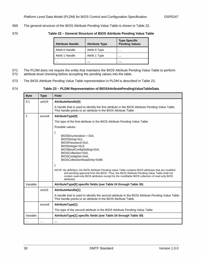
The general structure of the BIOS Attribute Pending Value Table is shown in Table 22. 569
570 Table 22 – General Structure of BIOS Attribute Pending Value Table
Attribute Handle Attribute Type Type Specific Pending Values
Attrib 0 Handle Attrib 0 Type …
Attrib 1 Handle Attrib 1 Type …
… … …
The PLDM does not require the entity that maintains the BIOS Attribute Pending Value Table to perform attribute-level checking before accepting the pending values into the table.
571 572
573
574
The BIOS Attribute Pending Value Table representation in PLDM is described in Table 23.
Table 23 – PLDM Representation of BIOSAttributePendingValueTableData
Byte Type Field
0:1 uint16 AttributeHandle[0]
A handle that is used to identify the first attribute in the BIOS Attribute Pending Value Table. This handle points to an attribute in the BIOS Attribute Table.
2 enum8 AttributeType[0]
The type of the first attribute in the BIOS Attribute Pending Value Table
Possible values:
{ BIOSEnumeration = 0x0, BIOSString=0x1, BIOSPassword=0x2, BIOSInteger=0x3, BIOSBootConfigSetting=0x4, BIOSCollection=0x5, BIOSConfigSet=0x6, BIOSCollectionReadOnly=0x85
} NOTE: By definition, the BIOS Attribute Pending Value Table contains BIOS attributes that are modified
and pending approval from the BIOS. Thus, the BIOS Attribute Pending Value Table shall not contain read-only BIOS attributes except for the modifiable BIOS collection of read-only BIOS attributes.
Variable AttributeType[0] specific fields (see Table 24 through Table 30)
uint16 AttributeHandle[1]
A handle that is used to identify the second attribute in the BIOS Attribute Pending Value Table. This handle points to an attribute in the BIOS Attribute Table.
enum8 AttributeType[1]
The type of the second attribute in the BIOS Attribute Pending Value Table
Variable AttributeType[1] specific fields (see Table 24 through Table 30)
… … …

DSP0247 Platform Level Data Model (PLDM) for BIOS Control and Configuration Specification
Version 1.0.0 DMTF Standard 31
Byte Type Field
Variable … Pad
0 to 3 number of pad bytes. The value stored in each pad byte is 0x00.
The transmitter can compute the number of pad bytes from the BIOSAttributePendingValueTableData by using the following algorithm:
Let L be the total number of bytes in the BIOSAttributePendingValueTableData excluding the pad and the integrity checksum.
if (L modulo 4 == 0) then NumPadBytes = 0; else NumPadBytes = 4 – L modulo 4;
The receiver can compute the number of pad bytes from the BIOSAttributePendingValueTableData by using the following algorithm. In the algorithm, the receiver parses BIOS Attribute Pending Value Table data until the remaining bytes are less than 8. When it reaches that stage, the remaining bytes contain the pad bytes and four bytes of data integrity checksum.
Let L be the total number of bytes in the BIOSAttributePendingValueTableData including the pad and the integrity checksum.
RemBytes = L;
i = 0;
while (RemBytes >= 8)
{
Process the ith attribute in the table;
RemBytes = RemBytes - 3 – Length of ith attribute type specific fields;
i = i+1;
}
NumPadBytes = RemBytes modulo 4;
… uint32 BIOSAttributePendingValueTableIntegrityChecksum
Integrity checksum on the BIOSAttributePendingValueTableData shown above including the pad information.
For this specification, the CRC-32 algorithm with the polynomial x32 + x26 + x23 + x22 + x16 + x12 + x11 + x10 + x8 + x7 + x5 + x4 + x2 + x + 1 (same as the one used by IEEE 802.3) must be used for the integrity checksum computation. The CRC computation involves processing a byte at a time with the least significant bit first.
The specific fields for the BIOSEnumeration type are described in Table 24. 575
576 Table 24 – Specific BIOS Attribute Pending Value Table Fields for the BIOSEnumeration Type
Byte Type Field
0 uint8 NumberOfPendingValues (N)
Total number of pending values for this enumeration
1 uint8 PendingValueStringHandleIndex[0]
An index into the array of the possible values of string handles for the first pending value. This index points to an entry in the array of string handles representing possible values for this attribute provided in the BIOS Attribute Table.
… … …

Platform Level Data Model (PLDM) for BIOS Control and Configuration Specification DSP0247
32 DMTF Standard Version 1.0.0
Byte Type Field
N uint8 PendingValueStringHandleIndex[N-1]
An index into the array of the possible values of string handles for the Nth pending value. This index points to an entry in the array of string handles representing possible values for this attribute provided in the BIOS Attribute Table.
The string handle index in Table 24 is an 8-bit index into the array (provided in the BIOS Attribute Table) of the possible values of string handles for this attribute.
577 578
579
580
The specific fields for the BIOSString type are described in Table 25.
Table 25 – Specific BIOS Attribute Pending Value Table Fields for the BIOSString Type
Byte Type Field
0:1 uint16 PendingStringLength
The length of the pending string in bytes
Variable PendingString
The pending string itself
The specific fields for the BIOSPassword type are described in Table 26. 581
582 Table 26 – Specific BIOS Attribute Pending Value Table Fields for the BIOSPassword Type
Byte Type Field
0:1 uint16 PendingPasswordLength
The length of the pending password in bytes
Variable PendingPassword
The pending password
The specific fields for the BIOSInteger type are described in Table 27. 583
584 Table 27 – Specific BIOS Attribute Pending Value Table Fields for the BIOSInteger Type
Byte Type Field
0:7 uint64 PendingValue
The pending value of the integer

DSP0247 Platform Level Data Model (PLDM) for BIOS Control and Configuration Specification
Version 1.0.0 DMTF Standard 33
The specific fields for the BIOSBootConfigSetting type are described in Table 28. 585
586 587
Table 28 – Specific BIOS Attribute Pending Value Table Fields for the BIOSBootConfigSetting Type
Byte Type Field
0 enum8 BootConfigType
The type of the boot configuration
Possible values:
{
Unknown (0x00) – A template boot configuration whose type is not known. This configuration is not known to be default, next, or one-time.
Default (0x01) – The default configuration for the BIOS boot configuration.
Next (0x2) – The next boot configuration that is maintained across the boots.
DefaultAndNext (0x3) – The default configuration that is used as the next boot configuration that is maintained across the boots. In this case, the BIOS uses the same boot configuration for both default and next boot configuration.
Onetime (0x4) – The one-time boot configuration that is used for the next boot only.
DefaultAndOnetime (0x5) – The default configuration that is used as one-time boot configuration for the next boot only. In this case, the BIOS uses the same boot configuration for both default and one-time boot configuration.
}
1 enum8 OrderAndFailThroughMode
Possible values:
{
UnorderedAndLimitedFailThrough (0x00) – The boot sources specified in the array below can be applied in any order and in the case of failure to boot from the boot sources specified in the array, other boot sources that are specified as possible boot sources for this attribute in the BIOS Attribute Table shall not be tried.
UnorderedAndFailThrough (0x01) – The boot sources specified in the array below can be applied in any order and in the case of failure to boot from the boot sources specified in the array, other boot sources that are specified as possible boot sources for this attribute in the BIOS Attribute Table can be tried in any order.
OrderedAndLimitedFailThrough (0x02) – The boot sources specified in the array below must be applied in the order specified in the array and in the case of failure to boot from the boot sources specified in the array, other boot sources that are specified as possible boot sources for this attribute in the BIOS Attribute Table shall not be tried.
OrderedAndFailThrough (0x03) – The boot sources specified in the array below must be applied in the order specified in the array and in the case of failure to boot from the boot sources specified in the array, other boot sources that are specified as possible boot sources for this attribute in the BIOS Attribute Table can be tried in any order.
}
2 uint8 NumberOfPendingBootSourceSettings (N)
Specifies the number of boot source settings that are in the pending boot configuration

Platform Level Data Model (PLDM) for BIOS Control and Configuration Specification DSP0247
34 DMTF Standard Version 1.0.0
Byte Type Field
3 uint8 BootSourceStringHandleIndex[0]
An index into the array of the possible values of string handles for the first boot source setting value. This index points to an entry in the array of string handles representing possible values for this attribute provided in the BIOS Attribute Table.
4 uint8 BootSourceStringHandleIndex[1]
An index into the array of the possible values of string handles for the second boot source setting value. This index points to an entry in the array of string handles representing possible values for this attribute provided in the BIOS Attribute Table.
… … …
N+2 uint8 BootSourceStringHandleIndex[N-1]
An index into the array of the possible values of string handles for the Nth boot source setting value. This index points to an entry in the array of string handles representing possible values for this attribute provided in the BIOS Attribute Table.
The string handle index in Table 28 is an 8-bit index into the array (provided in the BIOS Attribute Table) of the possible boot source string handles for this attribute.
588 589
590 591 592
593 594 595 596
597 598 599
600 601 602 603
604 605 606
607 608
609 610
The BIOS Attribute Pending Value Table can contain changes to the settings for multiple boot configurations. When multiple BIOS attributes of type BIOSBootConfigSetting are provided in the BIOS Attribute Pending Value Table, the following rules apply:
• At most one BIOS attribute shall exist among the BIOS attributes of type BIOSBootConfigSetting with BootConfigType set to Default, DefaultAndNext, or DefaultAndOnetime. In other words, the BIOS Attribute Pending Value Table shall contain at most one default boot configuration.
• At most one BIOS attribute shall exist among the BIOS attributes of type BIOSBootConfigSetting with BootConfigType set to Next or DefaultAndNext. In other words, the BIOS Attribute Pending Value Table shall contain at most one next boot configuration.
• At most one BIOS attribute shall exist among the BIOS attributes of type BIOSBootConfigSetting with BootConfigType set to Onetime or DefaultAndOnetime. In other words, the BIOS Attribute Pending Value Table shall contain at most one onetime boot configuration.
• For the next boot, the boot configuration with BootConfigType set to Onetime or DefaultAndOnetime takes precedence over the boot configuration with BootConfigType set to Next or DefaultAndNext.
The specific fields for the BIOSCollection and BIOSCollectionReadOnly types are described in Table 29.
Table 29 – Specific BIOS Attribute Pending Value Table Fields for BIOSCollection and BIOSCollectionReadOnly Types
Byte Type Field
0 uint8 NumberOfAttributes (N)
The number of BIOS attributes that belong to the pending value of the BIOS collection
1:2 uintt16 AttributeHandle[0]
A handle that is used to identify the first attribute in the pending value of the BIOS collection. This handle points to an attribute in the BIOS Attribute Table.

DSP0247 Platform Level Data Model (PLDM) for BIOS Control and Configuration Specification
Version 1.0.0 DMTF Standard 35
Byte Type Field
.. uint16 ….
2N-1:2N uint16 AttributeHandle[N-1]
A handle that is used to identify the Nth attribute in the pending value of the BIOS collection. This handle points to an attribute in the BIOS Attribute Table.
The BIOS Attribute Pending Value Table shall not contain a BIOS attribute of type BIOSCollection or BIOSCollectionReadOnly with CollectionType set to UnorderedAndUnmodifiable or OrderedAndUnmodifiable. In other words, the BIOS Attribute Pending Value Table shall not contain an unmodifiable BIOS collection.
611 612 613 614
615 616
617
The specific fields for the BIOSConfigSet are described in Table 30. The BIOS Attribute Pending Value Table shall contain at most one attribute of type BIOSConfigSet.
Table 30 – Specific BIOS Attribute Pending Value Table Fields for the BIOSConfigSet Type
Byte Type Field
0 uint8 ConfigSetStringHandleIndex
An index into the array of the possible values of BIOS configuration sets. This index points to an entry in the array of string handles representing possible values for this attribute provided in the BIOS Attribute Table.
8 PLDM Commands for BIOS Control and Configuration 618
The PLDM commands for BIOS Control and Configuration are defined in this section. 619
620
621
Table 31 defines the PLDM command codes for the PLDM for BIOS Control and Configuration.
Table 31 – PLDM for BIOS Control and Configuration Command Codes
Command Code Value Requirement Section
GetBIOSTable 0x01 Mandatory 8.1
SetBIOSTable 0x02 Mandatory 8.2
UpdateBIOSTable 0x03 Optional 8.3
GetBIOSTableTags 0x04 Optional 8.4
SetBIOSTableTags 0x05 Optional 8.5
AcceptBIOSAttributesPendingValues 0x06 Mandatory 8.6
SetBIOSAttributeCurrentValue 0x07 Optional 8.7
GetBIOSAttributeCurrentValueByHandle 0x08 Optional 8.8
GetBIOSAttributePendingValueByHandle 0x09 Optional 8.9
GetBIOSAttributeCurrentValueByType 0x0a Optional 8.10
GetBIOSAttributePendingValueByType 0x0b Optional 8.11
GetDateTime 0x0c Conditional1 8.12

Platform Level Data Model (PLDM) for BIOS Control and Configuration Specification DSP0247
36 DMTF Standard Version 1.0.0
Command Code Value Requirement Section
SetDateTime 0x0d Conditional1 8.13
GetBIOSStringTableStringType 0x0e Optional 8.14
SetBIOSStringTableStringType 0x0f Optional 8.15 1These commands are optional, but if SetDateTime is implemented, then GetDateTime must be implemented.
The requirements specified in Table 31 are relative to the services provided by the PLDM terminus. A compliant implementation must support at least one type of BIOS attribute in the BIOS tables.
622 623
625 626
627
8.1 GetBIOSTable 624
The GetBIOSTable command, described in Table 32, is used by the MC (or BIOS) to get a table from the BIOS (or MC) using one or more PLDM requests. For multipart transfers, see 9.1.
Table 32 – GetBIOSTable Command
Byte Type Request Data
0:3 uint32 DataTransferHandle A handle that is used to identify a BIOS table transfer. This handle is ignored by the responder when the TransferOperationFlag is set to GetFirstPart.
4 enum8 TransferOperationFlag The transfer operation flag that indicates whether this is the start of a multipart transfer Possible values: {GetNextPart=0x00, GetFirstPart=0x01}
5 enum8 TableType Indicates what table is being transferred Possible values: {
BIOSStringTable=0x0, BIOSAttributeTable=0x1, BIOSAttributeValueTable=0x2, BIOSAttributePendingValueTable=0x3
}
Byte Type Response Data
0 enum8
CompletionCode Possible values: {
PLDM_BASE_CODES, INVALID_DATA_TRANSFER_HANDLE=0x80, INVALID_TRANSFER_OPERATION_FLAG=0x81, BIOS_TABLE_UNAVAILABLE=0x83, INVALID_BIOS_TABLE_DATA_INTEGRITY_CHECK=0x84, INVALID_BIOS_TABLE_TYPE=0x85
}
1:4 uint32 NextDataTransferHandle A handle that is used to identify the next portion of the transfer

DSP0247 Platform Level Data Model (PLDM) for BIOS Control and Configuration Specification
Version 1.0.0 DMTF Standard 37
Byte Type Response Data
5 enum8 TransferFlag The transfer flag that indicates what part of the transfer this response represents Possible values: {Start = 0x1, Middle = 0x2, End = 0x4, StartAndEnd = 0x5}
Variable -
TableData Table type specific data. See the data structures in Section 7.
8.2 SetBIOSTable 628
The SetBIOSTable command, described in Table 33, is used by the BIOS (or MC) to set a BIOS table on the MC using one or more PLDM requests. For multipart transfers, see
629 630
631
9.1.
Table 33 – SetBIOSTable Command
Byte Type Request Data
0:3 uint32 DataTransferHandle
A handle that is used to identify a BIOS table transfer. This handle is ignored by the responder when the TransferFlag is set to Start or StartAndEnd.
4 enum8 TransferFlag
The transfer flag that indicates what part of the transfer this request represents
Possible values: {Start = 0x1, Middle = 0x2, End = 0x4, StartAndEnd = 0x5}
5 enum8 TableType
Indicates what table is being transferred
Possible values:
{BIOSStringTable=0x0, BIOSAttributeTable=0x1, BIOSAttributeValueTable=0x2}
Variable – TableData
Table type specific data. See the data structures in 8.1.
Byte Type Response Data
0 enum8
CompletionCode
Possible values:
{ PLDM_BASE_CODES, INVALID_DATA_TRANSFER_HANDLE=0x80, INVALID_TRANSFER_FLAG=0x82, INVALID_BIOS_TABLE_DATA_INTEGRITY_CHECK=0x84, INVALID_BIOS_TABLE_TYPE=0x85 }
1:4 uint32 NextDataTransferHandle
A handle that is used to identify the next portion of the transfer

Platform Level Data Model (PLDM) for BIOS Control and Configuration Specification DSP0247
38 DMTF Standard Version 1.0.0
8.3 UpdateBIOSTable 632
The UpdateBIOSTable command, described in Table 34, is used by the BIOS (or MC) to update a BIOS table using one or more PLDM requests. This action involves updating the existing entries, adding new entries, or both. For multipart transfers, see
633 634 635 636
637
9.1. The BIOS (or MC) also provides the integrity checksum for the data transferred in this update.
Table 34 – UpdateBIOSTable Command
Byte Type Request Data
0:3 uint32 DataTransferHandle
A handle that is used to identify a BIOS table transfer. This handle is ignored by the responder when the TransferFlag is set to Start or StartAndEnd.
4 enum8 TransferFlag
The transfer flag that indicates what part of the transfer this request represents
Possible values: {Start = 0x1, Middle = 0x2, End = 0x4, StartAndEnd = 0x5}
5 enum8 TableType
Indicates what table is being transferred
Possible values:
{BIOSStringTable=0x0, BIOSAttributeTable=0x1, BIOSAttributeValueTable=0x2}
Variable - TableData
Table type specific data. See the data structures in the previous section.
Byte Type Response Data
0 enum8
CompletionCode
Possible values:
{ PLDM_BASE_CODES, INVALID_DATA_TRANSFER_HANDLE=0x80, INVALID_TRANSFER_FLAG=0x82, INVALID_BIOS_TABLE_DATA_INTEGRITY_CHECK=0x84, INVALID_BIOS_TABLE_TYPE=0x85 }
1:4 uint32 NextDataTransferHandle
A handle that is used to identify the next portion of the transfer
8.4 GetBIOSTableTags 638
The GetBiosTableTags command, described in Table 35, is used by the BIOS to query the tags of the BIOS tables maintained by the MC. The use of BIOS table tags is described in
639 640 6.6.

DSP0247 Platform Level Data Model (PLDM) for BIOS Control and Configuration Specification
Version 1.0.0 DMTF Standard 39
Table 35 – GetBIOSTableTags Command 641
Byte Type Request Data
0 uint8 NumberOfTables (N) 1 enum8 TableType[0]
Possible values: {BIOSStringTable=0x0, BIOSAttributeTable=0x1, BIOSAttributeValueTable=0x2}
2 enum8 …. N enum8 TableType[N-1]
Possible values: {BIOSStringTable=0x0, BIOSAttributeTable=0x1, BIOSAttributeValueTable=0x2}
Byte Type Response Data
0 enum8
CompletionCode Possible values: { PLDM_BASE_CODES, BIOS_TABLE_TAG_UNAVAILABLE=0x86, INVALID_BIOS_TABLE_TAG_TYPE=0x87 }
1:4 uint32 TableTag[0] … uint32 …. 4N-3:4N
uint32 TableTag[N-1]
8.5 SetBIOSTableTags 642
The SetBIOSTableTags command, described in Table 36, is used by the BIOS to set the tags of the tables that the MC maintains. The BIOS can use this command after updating the BIOS tables. The use of BIOS table tags is described in
643 644 645
646 647 648
649
6.6.
A table tag for a particular table type shall be specified at most one time in the request data. If multiple table tags for a particular table type are specified in the request, the responder may return an error or may process multiple tags in an order that is implementation specific.
Table 36 – SetBIOSTableTags Command
Byte Type Request Data
0 uint8 NumberOfTables (N) 1 enum8 TableType[0]
Possible values: {BIOSStringTable=0x0, BIOSAttributeTable=0x1, BIOSAttributeValueTable=0x2}
2:5 uint32 TableTag[0] … … …. 5*N-4 enum8 TableType[N-1]
Possible values: {BIOSStringTable=0x0, BIOSAttributeTable=0x1, BIOSAttributeValueTable=0x2}
5*N-3:5*N
uint32 TableTag[N-1]

Platform Level Data Model (PLDM) for BIOS Control and Configuration Specification DSP0247
40 DMTF Standard Version 1.0.0
Byte Type Response Data
0 enum8
CompletionCode Possible values : { PLDM_BASE_CODES, INVALID_BIOS_TABLE_TAG_TYPE=0x87 }
8.6 AcceptBIOSAttributesPendingValues 650
The AcceptBIOSAttributesPendingValues command, described in Table 37, is used by the BIOS to signal the MC of the acceptance of the pending values of the BIOS attributes. The pending values of the attributes not specified in these transfers are rejected by the BIOS. The MC must clear the pending table after processing this command.
651 652 653 654
655 Table 37 – AcceptBIOSAttributesPendingValues Command
Byte Type Request Data
0:3 uint32 DataTransferHandle
A handle that is used to identify this transfer. This handle is ignored by the responder when the TransferFlag is set to Start or StartAndEnd.
4 enum8 TransferFlag
The transfer flag that indicates what part of the transfer this request represents
Possible values: {Start=0x1, Middle=0x2, End=0x4, StartAndEnd = 0x5}
Variable - BIOSAttributesHandles (see Table 38)
Byte Type Response Data
0 enum8
CompletionCode
Possible values :
{ PLDM_BASE_CODES, INVALID_DATA_TRANSFER_HANDLE=0x80, INVALID_TRANSFER_FLAG=0x82, INVALID_BIOS_ATTR_HANDLE=0x88 }
1:4 uint32 NextDataTransferHandle
A handle that is used to identify the next portion of the transfer
The array of BIOS attribute handles at the PLDM level is represented as shown in Table 38. This data structure is transferred using the PLDM command described in this section. For more details on multipart data transfers, see
656 657 658 9.1.

DSP0247 Platform Level Data Model (PLDM) for BIOS Control and Configuration Specification
Version 1.0.0 DMTF Standard 41
Table 38 – PLDM Representation of BIOSAttributesHandles 659
Byte Type Field
0-1 uint16 NumberOfAttributeHandles
The total number of attribute handles present in this structure. This represents the number of accepted pending attribute changes. If the attribute handle for a pending attribute value is not present in this table, the pending value for that attribute shall be rejected and discarded. If all the pending attribute values are rejected, the NumberOfAttributeHandles shall be set to 0.
2-3 uint16 AttributeHandle[0]
A handle that is used to identify the first attribute in this structure. This handle points to an attribute in the BIOS Attribute Table.
… … …
… uint16 AttributeHandle[N-1]
A handle that is used to identify the Nth attribute in this structure. This handle points to an attribute in the BIOS Attribute Table.
Variable … Pad
0 or 2 pad bytes. The value stored in each pad byte is 0x00.
The number of pad bytes can be calculated as follows:
If (NumberOfAttributeHandles modulo 2 == 1) then NumberOfPadBytes = 0;
else NumberOfPadBytes = 2;
… uint32 BIOSAttributesHandlesIntegrityChecksum
Integrity checksum on the BIOS attribute handles shown above including the NumberOfAttributesHandles field and the pad information.
For this specification, the CRC-32 algorithm with the polynomial x32 + x26 + x23 + x22 + x16 + x12 + x11 + x10 + x8 + x7 + x5 + x4 + x2 + x + 1 (same as the one used by IEEE 802.3) must be used for the integrity checksum computation. The CRC computation involves processing a byte at a time with the least significant bit first.
8.7 SetBIOSAttributeCurrentValue 660
The SetBIOSAttributeCurrentValue command, described in Table 39, is used by the BIOS (or MC) to set the current value of a BIOS attribute on the MC using one or more PLDM requests. For multipart transfers, see
661 662 663
664
9.1.
Table 39 – SetBIOSAttributeCurrentValue Command
Byte Type Request Data
0:3 uint32 DataTransferHandle
A handle that is used to identify a BIOS table transfer. This handle is ignored by the responder when the TransferFlag is set to Start or StartAndEnd.
4 enum8 TransferFlag
The transfer flag that indicates what part of the transfer this request represents
Possible values: {Start=0x1, Middle=0x2, End=0x4, StartAndEnd = 0x5}
Variable … AttributeData
See Table 14 through Table 21 for the format of data. For this command, the AttributeData contains exactly one attribute whose current value is being set.

Platform Level Data Model (PLDM) for BIOS Control and Configuration Specification DSP0247
42 DMTF Standard Version 1.0.0
Byte Type Response Data
0 enum8
CompletionCode
Possible values :
{ PLDM_BASE_CODES, INVALID_DATA_TRANSFER_HANDLE=0x80, INVALID_TRANSFER_FLAG=0x82, }
1:4 uint32 NextDataTransferHandle
A handle that is used to identify the next portion of the transfer
8.8 GetBIOSAttributeCurrentValueByHandle 665
The GetBIOSAttributeCurrentValueByHandle command, described in Table 40, is used by the BIOS (or MC) to get the current value of a BIOS attribute (identified by an AttributeHandle) from the MC (or BIOS) using one or more PLDM requests. For multipart transfers, see
666 667 668
669
9.1.
Table 40 – GetBIOSAttributeCurrentValueByHandle Command
Byte Type Request Data
0:3 uint32 DataTransferHandle
A handle that is used to identify a BIOS attribute transfer. This handle is ignored by the responder when the TransferOperationFlag is set to GetFirstPart.
4 enum8 TransferOperationFlag
The operation flag that indicates whether this is the start of the transfer
Possible values: {GetNextPart=0x00, GetFirstPart=0x01}
5:6 uint16 AttributeHandle
A handle that is used to identify the BIOS attribute
Byte Type Response Data
0 enum8
CompletionCode
Possible values:
{ PLDM_BASE_CODES, INVALID_DATA_TRANSFER_HANDLE=0x80, INVALID_TRANSFER_OPERATION_FLAG=0x81, INVALID_BIOS_ATTR_HANDLE=0x88 }
1:4 uint32 NextDataTransferHandle
A handle that is used to identify the next portion of the transfer
5 enum8 TransferFlag
The transfer flag that indicates what part of the transfer this response represents
Possible values: {Start=0x1, Middle=0x2, End=0x4, StartAndEnd = 0x5}
Variable … AttributeData
See Table 14 through Table 21 for the format of data. For this command, the AttributeData contains exactly one attribute whose current value is being provided.

DSP0247 Platform Level Data Model (PLDM) for BIOS Control and Configuration Specification
Version 1.0.0 DMTF Standard 43
8.9 GetBIOSAttributePendingValueByHandle 670
The GetBIOSAttributePendingValueByHandle command, described in Table 41, is used by the BIOS (or MC) to get the pending value of a BIOS attribute (identified by an AttributeHandle) from the MC using one or more PLDM requests. For multipart transfers, see
671 672 673
674
9.1.
Table 41 – GetBIOSAttributePendingValueByHandle
Byte Type Request Data
0:3 uint32 DataTransferHandle
A handle that is used to identify a BIOS attribute transfer. This handle is ignored by the responder when the TransferOperationFlag is set to GetFirstPart.
4 enum8 TransferOperationFlag
The transfer operation flag that indicates whether this is the start of the transfer
Possible values: {GetNextPart=0x00, GetFirstPart=0x01}
5:6 uint16 BIOSAttributeHandle
A handle that is used to identify the BIOS attribute
Byte Type Response Data
0 enum8
CompletionCode
Possible values:
{ PLDM_BASE_CODES, INVALID_DATA_TRANSFER_HANDLE=0x80, INVALID_TRANSFER_OPERATION_FLAG=0x81, INVALID_BIOS_ATTR_HANDLE=0x88 }
1:4 uint32 NextDataTransferHandle
A handle that is used to identify the next portion of the transfer
5 enum8 TransferFlag
The transfer flag that indicates what part of the transfer this response represents
Possible values: {Start=0x1, Middle=0x2, End=0x4, StartAndEnd = 0x5}
Variable … AttributeData
See Table 23 through Table 30 for the format of data. For this command, the AttributeData contains exactly one attribute whose pending value is being provided.

Platform Level Data Model (PLDM) for BIOS Control and Configuration Specification DSP0247
44 DMTF Standard Version 1.0.0
8.10 GetBIOSAttributeCurrentValueByType 675
The GetBIOSAttributeCurrentValueByType command, described in Table 42, is used by the BIOS (or MC) to get the current values of BIOS attributes of a specific AttributeType from the MC (or BIOS) using one or more PLDM requests. For multipart transfers, see
676 677 678
679
9.1.
Table 42 – GetBIOSAttributeCurrentValueByType
Byte Type Request Data
0:3 uint32 DataTransferHandle
A handle that is used to identify a BIOS attribute transfer. This handle is ignored by the responder when the TransferOperationFlag is set to GetFirstPart.
4 enum8 TransferOperationFlag
The transfer operation flag that indicates whether this is the start of the transfer
Possible values: {GetNextPart=0x00, GetFirstPart=0x01}
5 enum8 AttributeType
The type of the BIOS attribute(s). Refer to Table 14 for the possible values of attribute type.
Byte Type Response Data
0 enum8
CompletionCode
Possible values:
{ PLDM_BASE_CODES, INVALID_DATA_TRANSFER_HANDLE=0x80, INVALID_TRANSFER_OPERATION_FLAG=0x81, INVALID_BIOS_ATTR_TYPE=0x89 }
1:4 uint32 NextDataTransferHandle
A handle that is used to identify the next portion of the transfer
5 enum8 TransferFlag
The transfer flag that indicates what part of the transfer this response represents
Possible values: {Start=0x1, Middle=0x2, End=0x4, StartAndEnd = 0x5}
Variable … AttributeData
See Table 14 through Table 21 for the format of data. For this command, the AttributeData contains the current values of all the BIOS attributes of the type specified in the AttributeType field in the request data.

DSP0247 Platform Level Data Model (PLDM) for BIOS Control and Configuration Specification
Version 1.0.0 DMTF Standard 45
8.11 GetBIOSAttributePendingValueByType 680
The GetBIOSAttributePendingValueByType command, described in Table 43, is used by the BIOS (or MC) to get the pending values of BIOS attributes of a specific AttributeType from the MC (or BIOS) using one or more PLDM requests. For multipart transfers, see
681 682 683
684
9.1.
Table 43 – GetBIOSAttributePendingValueByType Command
Byte Type Request Data
0:3 uint32 DataTransferHandle
A handle that is used to identify a BIOS attribute transfer. This handle is ignored by the responder when the TransferOperationFlag is set to GetFirstPart.
4 enum8 TransferOperationFlag
The transfer operation flag that indicates whether this is the start of the transfer
Possible values: {GetNextPart=0x00, GetFirstPart=0x01}
5 enum8 AttributeType
The type of the BIOS attribute(s). Refer to Table 23 for the possible values of attribute type.
Byte Type Response Data
0 enum8
CompletionCode
Possible values:
{ PLDM_BASE_CODES, INVALID_DATA_TRANSFER_HANDLE=0x80, INVALID_TRANSFER_OPERATION_FLAG=0x81, INVALID_BIOS_ATTR_TYPE=0x89 }
1:4 uint32 NextDataTransferHandle
A handle that is used to identify the next portion of the transfer
5 enum8 TransferFlag
The transfer flag that indicates what part of the transfer this response represents
Possible values: {Start=0x1, Middle=0x2, End=0x4, StartAndEnd = 0x5}
Variable … AttributeData
See Table 23 through Table 30 for the format of data. For this command, the AttributeData contains the current values of all the BIOS attributes of the type specified in the AttributeType field in the request data.

Platform Level Data Model (PLDM) for BIOS Control and Configuration Specification DSP0247
46 DMTF Standard Version 1.0.0
8.12 GetDateTime 685
The GetDateTime command, described in Table 44, is used to get the date and time information. 686
687 Table 44 – GetDateTime Command
Byte Type Request Data
– – None
Byte Type Response Data
0 enum8
CompletionCode
Possible values:
{
PLDM_BASE_CODES,
NO_DATE_TIME_INFO_AVAILABLE=0x8A
}
1 uint8 Seconds in BCD format – Valid range of values [0, 59]
2 uint8 Minutes in BCD format – Valid range of values [0, 59]
3 uint8 Hours in BCD format – Valid range of values [0, 23]
4 uint8 Day of the Month in BCD format – Valid range of values [1, 31]
5 uint8 Month in BCD format – Valid range of values [1, 12]
6:7 uint16 Year in BCD format (4 digits)
8.13 SetDateTime 688
The SetDateTime command, described in Table 45, is used to set the date and time information. 689
690 Table 45 – SetDateTime Command
Byte Type Request Data
0 uint8 Seconds in BCD format – Valid range of values [0, 59]
1 uint8 Minutes in BCD format – Valid range of values [0, 59]
2 uint8 Hours in BCD format – Valid range of values [0, 23]
3 uint8 Day of the Month in BCD format – Valid range of values [1, 31]
4 uint8 Month in BCD format – Valid range of values [1, 12]
5:6 uint16 Year in BCD format (4 digits)
Byte Type Response Data
0 enum8
CompletionCode
Possible values:
{
PLDM_BASE_CODES
}

DSP0247 Platform Level Data Model (PLDM) for BIOS Control and Configuration Specification
Version 1.0.0 DMTF Standard 47
8.14 GetBIOSStringTableStringType 691
The GetBIOSStringTableStringType command is used to get the type of strings used in the BIOS String Table.
692 693
694 Table 46 – GetBIOSStringTableStringType Command
Byte Type Request Data
--- --- None
Byte Type Response Data
0 enum8
CompletionCode
Possible values:
{
PLDM_BASE_CODES
}
1 enum8 StringType The type of strings used in the BIOS String Table Possible values:
{Unknown=0x00, ASCII=0x01, Hex=0x02, UTF-8=0x03, UTF-16LE=0x04, UTF-16BE=0x05, Vendor Specific=0xFF}
8.15 SetBIOSStringTableStringType 695
The SetBIOSStringTableStringType command is used to set the type of strings used in the BIOS String Table.
696 697
698 Table 47 – SetBIOSStringTableStringType Command
Byte Type Request Data
0 enum8 StringType The type of strings used in the BIOS String Table. Possible values:
{Unknown=0x00, ASCII=0x01, Hex=0x02, UTF-8=0x03, UTF-16LE=0x04, UTF-16BE=0x05, Vendor Specific=0xFF}
Byte Type Response Data
0 enum8
CompletionCode
Possible values:
{
PLDM_BASE_CODES,
INVALID_STRING_TYPE=0x8B
}

Platform Level Data Model (PLDM) for BIOS Control and Configuration Specification DSP0247
48 DMTF Standard Version 1.0.0
8.16 PLDM for BIOS Control and Configuration Version 699
The version of this PLDM for BIOS Control and Configuration specification shall be 1.0.0 (major version number 1, minor version number 0, update version number 0, and no alpha version).
700 701
For the GetPLDMVersion command described in DSP0240, the version of this specification is reported using the encoding as: 0xF1F0F000.
702 703
705 706 707
709 710 711 712
713 714
715 716 717 718
719 720
721
722
723
724
725 726
727 728
729 730
9 BIOS/MC PLDM Communications Examples 704
The previous two sections described the data structures and commands that the BIOS and the MC can use to communicate the information about the BIOS attributes. This section provides some examples of PLDM communications using the PLDM commands defined in this specification.
9.1 Multipart Transfers 708
The commands defined in section 8 for transferring BIOS table data or attribute data support multipart transfers. The Get* and Set* commands use flags and data transfer handles to perform multipart transfers. Following are some requirements for using TransferOperationFlag, TransferFlag, and DataTransferHandle for a given data transfer:
• For initiating a data transfer (or getting the first part of data) using a Get* command, the TransferOperationFlag shall be set to GetFirstPart in the request of the Get* command.
• For transferring a part other than the first part of data using a Get* command, the TransferOperationFlag shall be set to GetNextPart and the DataTransferHandle shall be set to the NextDataTransferHandle that was obtained in the response of the previous Get* command for this data transfer.
• The TransferFlag specified in the request of a Set* command or the response of a Get* command has the following meanings:
– Start, which is the first part of the data transfer
– Middle, which is neither the first nor the last part of the data transfer
– End, which is the last part of the data transfer
– StartAndEnd, which is the first and the last part of the data transfer
• The requester shall consider a data transfer complete when the TransferFlag in the response of a Get* command is set to End or StartAndEnd.
• The responder shall consider a data transfer complete when the TransferFlag in the request of a Set* command is set to End or StartAndEnd.
The following two examples show how multipart transfers can be performed using the generic mechanism defined in the commands.

DSP0247 Platform Level Data Model (PLDM) for BIOS Control and Configuration Specification
Version 1.0.0 DMTF Standard 49
EXAMPLE 1: In this example, the BIOS is transferring the BIOS String Table to the MC using the SetBIOSTable command. The transfer is divided into four parts.
731 732 Figure 1 shows the flow of the data transfer.
733
734 Figure 1 – Multipart BIOS Table Transfer Using the SetBIOSTable Command

Platform Level Data Model (PLDM) for BIOS Control and Configuration Specification DSP0247
50 DMTF Standard Version 1.0.0
EXAMPLE 2: In this example, the BIOS is transferring the BIOS Attribute Pending Value Table from the MC using the GetBIOSTable command. The transfer is divided into three parts.
735 736 Figure 2 shows the flow of the data transfer.
737
738
740 741 742 743 744 745 746
Figure 2 – Multipart BIOS Table Transfer Using the GetBIOSTable Command
9.2 BIOS Table Initialization on MC 739
In Figure 3, the BIOS sets the BIOS tables for the first time on the MC. No authentication of any entities occurs in this initialization example. The BIOS first queries the BIOS table tags using the GetBIOSTableTags command. The response from the MC to this command indicates that the MC does not have any BIOS table tags. Upon finding that the MC does not have the BIOS table tags, the BIOS initializes the BIOS tables (BIOS String Table, BIOS Attribute Table, and BIOS Attribute Value Table, in that order) on the MC by using SetBIOSTable command. At the end of the initialization, the BIOS sets up the BIOS table tags on the MC by using SetBIOSTableTags command.
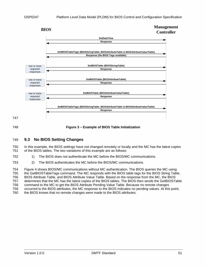
DSP0247 Platform Level Data Model (PLDM) for BIOS Control and Configuration Specification
Version 1.0.0 DMTF Standard 51
BIOS Management Controller
SetDateTimeResponse
GetBIOSTableTags (BIOSStringTable, BIOSAttributeTable & BIOSAttributeValueTable)
SetBIOSTable (BIOSStringTable)Response
SetBIOSTable (BIOSAttributeTable)
SetBIOSTable (BIOSAttributeValueTable)Response
SetBIOSTableTags (BIOSStringTable, BIOSAttributeTable & BIOSAttributeValueTable)Response
Response
Response (No BIOS Tags available)
one or more requests/responses
one or more requests/responses
one or more requests/responses
747
748
750 751
752
753
754 755 756 757 758 759 760
Figure 3 – Example of BIOS Table Initialization
9.3 No BIOS Setting Changes 749
In this example, the BIOS settings have not changed remotely or locally and the MC has the latest copies of the BIOS tables. The two variations of this example are as follows:
1) The BIOS does not authenticate the MC before the BIOS/MC communications.
2) The BIOS authenticates the MC before the BIOS/MC communications.
Figure 4 shows BIOS/MC communications without MC authentication. The BIOS queries the MC using the GetBIOSTableTags command. The MC responds with the BIOS table tags for the BIOS String Table, BIOS Attribute Table, and BIOS Attribute Value Table. Based on the response from the MC, the BIOS determines that the MC has the latest copies of the BIOS tables. The BIOS then sends the GetBIOSTable command to the MC to get the BIOS Attribute Pending Value Table. Because no remote changes occurred to the BIOS attributes, the MC response to the BIOS indicates no pending values. At this point, the BIOS knows that no remote changes were made to the BIOS attributes.

Platform Level Data Model (PLDM) for BIOS Control and Configuration Specification DSP0247
52 DMTF Standard Version 1.0.0
761
762
763
Figure 4 – BIOS/MC Communications without MC Authentication for No BIOS Settings Changes
Figure 5 is a variation of the preceding example with MC authentication.
BIOS Management Controller
SetDateTimeResponse
GetBIOSTableTags (BIOSStringTable, BIOSAttributeTable & BIOSAttributeValueTable)Response
GetBIOSAttributeCurrentValueByHandle (Current Password)Response
GetBIOSTable (BIOSPendingValueTable)Response (no pending values)
MC Authenticated
764
765
767 768 769
770 771 772 773
Figure 5 – BIOS/MC Communications with MC Authentication for No BIOS Settings Changes
9.4 Local BIOS Setting Changes 766
In Figure 6, the MC has the BIOS tables and the MC has no pending changes. The BIOS settings were locally modified and the BIOS provides the new BIOS settings to the MC. This example shows that the MC is authenticated before the transfer.
The BIOS first queries the current password from the MC by using the GetBIOSAttributeCurrentValueByType command. In the response, the BIOS receives the current password. The BIOS authenticates the MC with the password received in the response. After the MC is authenticated, the BIOS queries the BIOS table tags on the MC by using GetBIOSTableTags command.

DSP0247 Platform Level Data Model (PLDM) for BIOS Control and Configuration Specification
Version 1.0.0 DMTF Standard 53
The BIOS table tag for the BIOS Attribute Value Table in the response indicates to the BIOS that the BIOS settings on the MC are not the latest. The BIOS then uses the GetBIOSTable command to get any pending values of the BIOS attributes from the MC. The MC responds to the GetBIOSTable command with no pending values because no changes to the BIOS attributes were made remotely. Because the local BIOS setting were changed, the BIOS Attribute Value Table needs to be updated on the MC. The BIOS updates the copy of the BIOS Attribute Value Table on the MC by using the SetBIOSTable command.
774 775 776 777 778 779 780
781
782
784 785 786
787 788 789 790 791 792 793 794 795 796
Figure 6 – BIOS/MC Communications with MC Authentication for Local BIOS Settings Changes
9.5 Remote BIOS Setting Changes Accepted 783
In Figure 7, the MC has the BIOS tables and the MC has pending changes. The BIOS settings were not locally modified and the BIOS accepts the pending values obtained from the MC. This example shows that the MC is authenticated before the transfer.
The BIOS first queries the current password from the MC by using the GetBIOSAttributeCurrentValueByHandle command. In the response, the BIOS receives the current password. The BIOS authenticates the MC with the password received in the response. After the MC is authenticated, the BIOS queries the BIOS table tags on the MC by using GetBIOSTableTags command. The BIOS table tag for the BIOS Attribute Value Table in the response indicates to the BIOS that the MC has the latest BIOS String Table, BIOS Attribute Table, and BIOS Attribute Value Table. The BIOS then uses the GetBIOSTable command to get any pending values of the BIOS attributes from the MC. The MC responds to the GetBIOSTable command with the pending values because some of the BIOS attributes were changed by the remote entity. The BIOS modifies the BIOS attributes that had pending changes. The BIOS notifies the acceptance of pending values to the MC by using the

Platform Level Data Model (PLDM) for BIOS Control and Configuration Specification DSP0247
54 DMTF Standard Version 1.0.0
AcceptBIOSAttributesPendingValues command. This results in the MC updating its copy of the BIOS Attribute Value Table to reflect the acceptance of the pending values. The BIOS updates the table tag of BIOS Attribute Value Table to reflect the latest BIOS Attribute Value Table on the MC.
797 798 799
BIOS Management Controller
SetDateTimeResponse
GetBIOSTableTags (BIOSStringTable, BIOSAttributeTable & BIOSAttributeValueTable)
AcceptBIOSAttributePendingValues (BIOS accepts all pending values)Response
SetBIOSTableTags (BIOSAttributeValueTable)Response
Response
GetBIOSTable (BIOSAttributePendingValueTable)Response (pending values)
one or more requests/
responses
one or more requests/
responses
GetBIOSAttributeCurrentValueByHandle (Current Password)Response
MC Authenticated
800
801 802
Figure 7 – BIOS/MC Communications with MC Authentication (Based on Current Password) for Remote BIOS Settings Changes

DSP0247 Platform Level Data Model (PLDM) for BIOS Control and Configuration Specification
Version 1.0.0 DMTF Standard 55
Figure 8 is a variation of Figure 7, with the use of a pending password for the MC authentication. 803
804
805 806
807
Figure 8 – BIOS/MC Communications with MC Authentication (Based on Pending Password) for Remote BIOS Settings Changes

Platform Level Data Model (PLDM) for BIOS Control and Configuration Specification DSP0247
56 DMTF Standard Version 1.0.0
ANNEX A (informative)
Change Log
808 809 810 811 812
Version Date Author Description
1.0.0 2008/10/24 Hemal Shah Preliminary release draft 1.0.0 2008/11/5 Hemal Shah Addressed Platform SC comments. Preliminary release. 1.0.0 2009/4/23 DMTF Standard Release
813