PLC training system L20 RE 00877-B/06.07 (snap-in ...
24
Operating instructions RE 00877-B/06.07 PLC training system L20 (snap-in)
Transcript of PLC training system L20 RE 00877-B/06.07 (snap-in ...

Operating instructions
RE 00877-B/06.07PLC training system L20 (snap-in)


Table of contents1. Safety regulations ..............................................................................................................................4
General ..................................................................................................................................... 4Signs and symbols used ...................................................................................................... 4
2. Intended use .........................................................................................................................................5
3. Scope of delivery ................................................................................................................................6
4. Assembly / Commissioning .........................................................................................................7General ..................................................................................................................................... 7Commissioning PLC training system ................................................................................. 7Commissioning PLC IndraControl L20 ............................................................................. 8PLC programming device (prerequisites) ........................................................................ 8Displaying/changing the Ethernet setting of the PLC ................................................... 8Restoring archived projects ................................................................................................. 9Loading projects from the PLC programming device into the PLC .........................10Adjusting object-related communication settings ........................................................12Displaying the firmware version of the PLC ...................................................................15
5. Technical data ....................................................................................................................................18PLC training system 16DI, 12DO 0.5A, 6DO 2.0 A ....................................................18PLC training system 12DI, 12DO 0.5A ...........................................................................20
Notes........................................................................................................................................................... 22
RE 00877-B/06.07 | Operating Instructions Bosch Rexroth AG 3/24

1. Safety regulations
Before commissioning the device, read the product description. Make sure that the produce is suitable for the application concerned without any limitations. Non-com-pliance with application information or technical specifications may cause material damage or personal injury.
GeneralThese instructions serve the familiarization with the PLC training system and are to simplify the utilization of its intended applications.
The operating instructions contain important information in order to operate the PLC training system in a safe and proper way. Compliance with this information helps:
to avoid dangers•to reduce repair costs and downtimes•to increase the system's reliability and lifetime•
These instructions are to be read and applied by each person who is commissioned with work at the PLC training system, like:
operation•troubleshooting in the work cycle•control, service and maintenance works•
Apart from these operating instructions, you also have to comply with the provisions regarding accident prevention and environmental protection valid in the country of the user and at the place of installation.
Signs and symbols usedIn these instructions, the following signs and symbols are used:
Activity symbol: The text after this symbol describes activities that are to be com- ³pleted in the specified order, from top to bottom.
Result symbol: The text after this symbol describes the result of an activity. 3
This symbol is followed by information regarding content and structures. They serve as orientation aid for the reader.
Special safety regulations are available at the respective places. They are marked using the following symbols.
General danger spot
This symbol is followed by activities with which there is the danger of personal injuries and considerable material damage.
4/24 Bosch Rexroth AG Operating Instructions | RE 00877-B/06.07
WARNING SIGN(S)

2. Intended use
The PLC training system may only be used to impart control tasks with the program-mable logic controller IndraControl L20 in the technical industrial training.
Via the secure 4 mm technology of the supplied I/O boxes, sensors can be read out and actuators can be activated.
If the digital outputs (DO2-2A), the analog inputs (AI2) and the analog outputs (AO2) are used, the sensors and actuators are directly connected to the PLC. Conversion to 4 mm technology is not intended.
The input / output assemblies DO-2A, AI2 and AO2 are available as optional accessory, depending on the device configuration.
RE 00877-B/06.07 | Operating Instructions Bosch Rexroth AG 5/24

3. Scope of delivery
Before the initial commissioning, check the scope of delivery of the PLC training system.
1x training system L20 (snap-in)•1x compact flash card: firmware L20 (FWA-CML20*-IL*…)•1x CD: software IndraWorks (SWA-IWORKS-IL*…)•2x I/O box with 4 mm laboratory sockets (snap-in)•2x D-Sub connection cable 26-pole for I/O boxes (snap-in)•1x laboratory cable 4 mm (contact protected) blue•1x laboratory cable 4 mm (contact protected) blue•1x CD: documentations•
6/24 Bosch Rexroth AG Operating Instructions | RE 00877-B/06.07

4. Assembly / Commissioning
GeneralThe PLC training system is designed for assembly at a Rexroth grooved plate (groove 8, grid 25 mm) or at a Rexroth grooved sheet. They are used in the following carrier plates:
Rexroth grooved sheet case •Rexroth EcoDesk•Rexroth DS3•Rexroth DS4 •
Risks of accident during assembly works
Ensure that the snap-in fastening is securely engaged. Components could fall down and thus be damaged and cause injuries with the operating personnel.
Commissioning PLC training systemMount the PLC training system to an appropriate carrier plate. ³
Mount the I/O boxes next to the PLC training system (preferably on the right). ³
Connect the D-Sub sockets (INPUT, OUTPUT) at the PLC training system with ³the D-SUB plugs at the I/O boxes using the delivered connection cable and tighten the screws of the plug.
Insert the firmware (Compact Flash card) carefully into the provided interface at ³the IndraControl L20 (see projecting IndraControl L20).
Connect the 4 mm laboratory sockets (24 VDC red, 0 VDC blue) to the PLC ³training system with an appropriate voltage supply (see "technical data")
Install the "IndraWorks" software on a suitable programming device (PC / laptop) ³
Establish the connection between programming device and PLC using ³an Ethernet cable (10-Base-T, CAT.5, crosslink, RF45 plugs on both sides) (optional accessory).
The PLC training system is ready for operation 3
RE 00877-B/06.07 | Operating Instructions Bosch Rexroth AG 7/24
WARNING!

Commissioning PLC IndraControl L20
PLC programming device (prerequisites)
For configuring and programming the PLC training system, a PLC programming device coupled via Ethernet is necessary.
Hardware prerequisites
Class of a current standard PC•Min. 512 MB RAM memory•Min. 2 GB free hard disc space•Ethernet connection with RJ45 socket•
Software prerequisites
Operating system Microsoft Windows 2000 professional or higher•Installed Internet protocol (TCP/IP) on the PC•Correct installation of the supplied "IndraWorks" programming environment „Indra-•Works“ (on the PLC projecting and configuration)Correct installation of the supplied "IndraLogic" PLC programming software (for •creating and testing PLC programs)
Displaying/changing the Ethernet setting of the PLC
A correct adjustment of the IP addresses, the subnetwork and the gateway (if ap-plicable) is required for the communication between the PLC IndraControl L20 and the PLC programming device. For doing so, you have to know the current Ethernet settings of the PLC and change them, if required.
The Ethernet settings can also be displayed/changed without being connected with the PLC programming device.
A failure of the network is possible by making arbitrary settings!
The IP addresses in the Ethernet network have to be clearly identifiable. It is not al-lowed to use any duplicates. Ask your network administrator which settings are to be used! Comply with the speci-fications of your network administrator if the devices are supposed to be connected to a superior network!
Press the <Enter> key at the PLC. ³
Press the <down> key (down arrow key) as often as required until the display ³shows the word "Ethernet".
Press the <Enter> key. ³
The current 3 IP address of the PLC (e.g. "192.168.0.1") will be displayed as a ticker. Make a note of the IP address.
Press the <down> key. ³
The 3 subnetwork of the PLC will be displayed as a ticker (e.g. "255.255.255.0") . Make a note of the values.
Press the <down> key. ³
The IP address of the 3 gateway will be displayed as a ticker (e.g. "192.168.0.254"). Make a note of the values.
CAUTION!
Show settings
NOTE:
8/24 Bosch Rexroth AG Operating Instructions | RE 00877-B/06.07

Press the <down> key. ³
The (unchangeable) 3 MAC address will be displayed as a ticker. Make a note of the values.
If the settings are not to be changed, press the <Esc> key of the PLC twice to ³return to the "standard display". If settings are to be changed, proceed as follows:
Press the <down> key as often as required until the setting to be changed (IP ³address, subnetwork , gateway is shown in the display of the PLC as ticker.
Press the <Enter> key. The letter string "AAA:" is displayed for labelling the first ³address byte followed by its current decimal value.
Set the required value with the <up> and <down> keys. ³
Confirm your settings by pressing the <Enter> key. ³The letter string "BBB:" is displayed for labelling the second address byte fol-lowed by its current decimal value.
Set the other address bytes (BBB, CCC, DDD) as described above. ³After having confirmed the last setting, the system displays a message "OK?" whether the new address value should be applied or not.
Press the <Enter> key to confirm. The new address value will be displayed, writ- ³ten to the Compact Flash card and used from the next start of the PLC. If you do not wish to confirm, you can reject the change by pressing the <Esc> key. The previous address value will remain effective. In both cases, the PLC subsequently shows the current settings as a ticker on the display.
In order to change more settings, proceed with step 8. ³Otherwise press the <Esc> key of the PLC twice to return to the "standard display".
If you have changed the settings, the PLC must be restarted. ³
After the restart, the new Ethernet settings of the PLC will be activated. 3
Restoring archived projects
In "IndraWorks Engineering", devices and resources are referred to as "projects" and displayed in the project explorer as tree structure. The "project object" is always located on the highest hierarchy level in the project explorer and exactly represents 1 project. It may contain several devices, communication connections, functions or also structural elements (e.g. folders).
Under "IndraWorks Engineering", a complete project can be archived in a "zip" file. This "zip" file contains the whole information regarding the configuration and pro-gramming of the devices involved (here: PLC), is automatically packed upon saving and is thus particularly suitable for the smooth transfer of a project to another PLC programming device.
In order to load an archived project into the "IndraWorks Engineering" project ex-plorer, proceed as follows:
In the further course, a project that has already been opened in the project explorer is automatically closed. Thus, save any project that might already have been opened before loading an archived project into the project explorer, if necessary.
In IndraWorks Engineering, select the menu sequence "Project/Restoration". The ³"Restore project from archive" window appears.
Select "Restoration from file system" and activate the "Next" pushbutton. ³
Change settings
NOTE:
RE 00877-B/06.07 | Operating Instructions Bosch Rexroth AG 9/24

Actuate the "..." pushbutton and select the desired zip file. ³Confirm your selection by means of the "Open" pushbutton. The selection dialog is closed.
Ensure in the "Restore project from archive" window that the correct ³zip file has been specified. If this is the case, activate the "Next" pushbutton.
Using the "..." pushbutton, select a target directory. The project archived in the ³zip file, will then be unpacked into this target directory in the form of a new subdirectory. Confirm your selection by means of the "OK" pushbutton.
Ensure in the "Restore project from archive" window that the correct ³target directory has been specified. If yes, actuate the "Next" pushbutton. In the "Restore project from archive" window, the system will show you the selected settings.
Check whether all specifications are correct. If yes, actuate the "Complete" ³pushbutton. The zip file will be unpacked.
Select the "Open project when quitting the assistant" checkbox in order to open ³the project immediately after unpacking in the IndraWorks Engineering project explorer and actuate the "Close" pushbutton.
Confirm a conversion inquiry that might appear using the "Yes" pushbutton. ³
The archived project is unpacked in the specified target directory and opened in 3the project explorer.
Loading projects from the PLC programming device into the PLC
Firstly, the creation of a PLC program will exclusively take place on the PLC program-ming device under "IndraWorks Engineering" using the embedded "IndraLogic" application.
If your PLC program has reached a testable condition, it can be compiled into a lan-guage understandable for the target PLC and loaded into the PLC (download).
Prerequisites:
The project is loaded in the IndraWorks project explorer.•
Check the Ethernet settings used. ³For this purpose, firstly expand the project tree (click on plus symbol) until the relevant object "Logic" is displayed:
1: "Logic" object Fig. 0-1: Project tree with "Logic" object (example)
10/24 Bosch Rexroth AG Operating Instructions | RE 00877-B/06.07
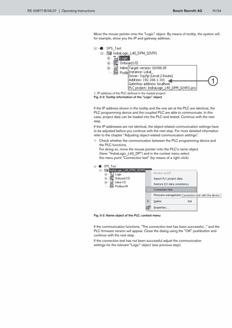
Move the mouse pointer onto the "Logic" object. By means of tooltip, the system will, for example, show you the IP and gateway address:
1: IP address of the PLC defined in the loaded project Fig. 0-2: Tooltip information of the "Logic" object
If the IP address shown in the tooltip and the one set at the PLC are identical, the PLC programming device and the coupled PLC are able to communicate. In this case, project data can be loaded into the PLC and tested. Continue with the next step.
If the IP addresses are not identical, the object-related communication settings have to be adjusted before you continue with the next step. For more detailed information refer to the chapter "Adjusting object-related communication settings".
Check whether the communication between the PLC programming device and ³the PLC functions. For doing so, move the mouse pointer onto the PLC's name object (here: "IndraLogic_L40_DP") and in the context menu select the menu point "Connection test" (by means of a right click).
Fig. 0-3: Name object of the PLC: context menu
If the communication functions, "The connection test has been successful..." and the PLC firmware version will appear. Close the dialog using the "OK" pushbutton and continue with the next step.
If the connection test has not been successful adjust the communication settings for the relevant "Logic" object (see previous step).
RE 00877-B/06.07 | Operating Instructions Bosch Rexroth AG 11/24

In IndraWorks Engineering, open the context menu of the "Logic" object ³(by means of a right click) and select the menu item "Start IndraLogic". The "IndraLogic" application will be started after having been checked for correct path specifications (if necessary, activate new paths proposed by the system by means of the "Accept" pushbutton!) with the project-related settings and compo-nents. In this condition, the program active in the PLC will not be changed, yet.
In the "IndraLogic" window, select the menu sequence "Project/Compile all" ³in order to check the PLC program for errors. If no errors are notified, change to the next step. Otherwise, correct your program.
In the "IndraLogic" window, select the menu sequence "Online/Login" in order to ³compile the program and transfer it into the PLC (= download). If the data to be loaded and the PLC data that is currently active is different, the system will request a confirmation:
"Yes" pushbutton: 1. Recompile program, download it into the PLC and start the PLC monitor operation for displaying the PLC program. As a consequence of this selection, data already existing in the PLC will be overwritten.
"No" pushbutton: 2. Start monitor operation for existing program in PLC.
"Cancel" pushbutton: 3. Cancel the compilation and download function. PLC monitor operation is not activated. The data in the PLC is not changed.
"Details" pushbutton: 4. Show differences between the data to be loaded and the active PLC data.
If the "Yes" pushbutton has been actuated, the system will load the new data into the PLC and start the PLC monitor operation.
In the "IndraLogic" window, select the menu sequence "Online/Start" in order to ³start the program and the PLC and/or "Online/Stop" in order to stop a started program. The PLC will show you the current state in its display (RUN or STOP).
If the PLC monitor operation is started, the "IndraLogic" application will show you the current state of all signals online:
Signal active: "TRUE" (red) Signal inactive: "FALSE" (black).
Thus, you can keep track of all signal changes on the display of your PLC pro- 3gramming device.
If you want to define the loaded project as ³ boot project, select the menu se-quence "Online/Create boot project" in the "IndraLogic" window. After the PLC start-up, a boot project will start automatically.
More information in connection with the boot project is contained in the online help on the "IndraLogic" PLC programming software.
Deactivate the PLC monitor operation if the test is completed. For doing so, ³select the menu sequence "Online/Logoff" in IndraLogic.
Adjusting object-related communication settings
The PLC programming device will only be able to communicate with a connected PLC if the Ethernet settings of the PLC object loaded in "IndraWorks Engineering" comply with the parameterized Ethernet setting of the PLC. Otherwise, the loading of programs into the PLC or the PLC monitor operation at the PLC programming device will not be possible.
Define boot project
12/24 Bosch Rexroth AG Operating Instructions | RE 00877-B/06.07

Prerequisites:
The project is loaded in the IndraWorks project explorer.•The parameterized Ethernet setting of the PLC is known •(also see chapter "Displaying/changing the Ethernet setting of the PLC").
For this purpose, firstly expand the project tree (click on plus symbol) in the "In- ³draWorks Engineering" window until the relevant "Logic" object is shown:
1: "Logic" object Fig. 0-4: Project tree (example)
Move the mouse pointer onto the "Logic" object and select ³the menu item "Properties..." (right mouse key) via the context menu
The "Properties" window is opened. 3
Fig. 0-5: "Properties" of the "Logic" object
When opening this dialog, the "IndraLogic Gateway Server" background process is started automatically (if not active yet) via which the communication will be pro-cessed.
NOTE:
RE 00877-B/06.07 | Operating Instructions Bosch Rexroth AG 13/24

Select the "Communication settings" tab in order to be shown detailed informa- ³tion on the Ethernet setting of the PLC defined in the loaded project. Selection of a communication setting is possible by means of the "Channels" dropdown list. The system will always show you the related parameter values in the grayed out fields.
The "Target address" parameter must contain the IP address of your PLC.1.
"Set gateway" must be assigned the entry "LocalHost".2.
If all parameters are correct, close the window using the "OK" pushbutton. ³If the settings of existing communication channels are not correct, create a new communication channel. For doing so, click on "Communication parameter...".
The "Communication parameter" window opens. 3
(1) Names of all communication channels that have already been defined. (2) Parameters of the communication channel selected under (1). Fig. 0-6: Creating a new communication channel
Click on the "New..." pushbutton in order to create a new communication channel. ³
The following dialog appears:
(1) Freely selectable name for the new communication channel. (2) Available drivers for the communication between the PLC programming device and the PLC. Fig. 0-7: Driver selection for new communication channel
14/24 Bosch Rexroth AG Operating Instructions | RE 00877-B/06.07

Enter a name for the new communication channel. ³
Select a suitable communication driver (in the "Name" column, click onto the cor- ³responding line, see fig. 0-7). Available drivers:
Tcp/Ip:1. Communication via ETH interface (X7E) via TCP/IP protocol
Serial (RS232):2. Communication via RS232 interface (X3C)
Tcp/Ip (level 2 route):3. Communication via ETH interface (X7E) via TCP/IP protocol. Difference regarding Tcp/Ip: extended package size.
In the communication via ETH interface, you should use the Tcp/Ip (level 2 route) driver for performance reasons.
Confirm your selection by means of the "OK" pushbutton.
The new communication channel appears in area 1 (see fig. 0-8).
Fig. 0-8: Adjusting parameters of a communication channel
Select the new communication channel in area 1 (left click) in order to adjust its ³parameters. For doing so, double click on the relevant line in area 2 (see fig. 0-8) and change the entry in the "Value" column according to your requirements. Address: IP address of the PLC Port: Port via which the communication at the PLC is processed Always complete the changes in each field using the <Enter> key!
Accept the displayed settings by means of the "OK" pushbutton. ³
Select the communication channel you have just been parameterizing via the ³"Channels" dropdown list (see fig. 0-5).
Displaying the firmware version of the PLC
In order to create own projects with PLC devices in IndraWorks Engineering, you must know the firmware version of the coupled PLC. This is necessary as the firmware version may affect the behavior/functional scope of the device.
• If currently, there is a functioning communication connection between the PLC programming device and the PLC concerned, move the mouse pointer on the name object of the PLC (here: "IndraLogic_L40_DP") and select the menu item "Con-nection test" (right click) in the context menu.
Display at the PLC programming device
NOTE:
RE 00877-B/06.07 | Operating Instructions Bosch Rexroth AG 15/24
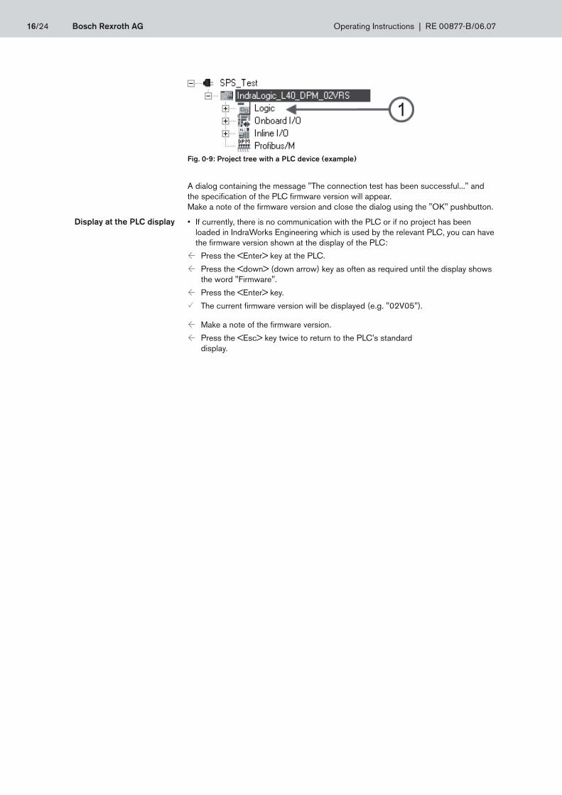
Fig. 0-9: Project tree with a PLC device (example)
A dialog containing the message "The connection test has been successful..." and the specification of the PLC firmware version will appear. Make a note of the firmware version and close the dialog using the "OK" pushbutton.
If currently, there is no communication with the PLC or if no project has been •loaded in IndraWorks Engineering which is used by the relevant PLC, you can have the firmware version shown at the display of the PLC:
Press the <Enter> key at the PLC. ³
Press the <down> (down arrow) key as often as required until the display shows ³the word "Firmware".
Press the <Enter> key. ³
The current firmware version will be displayed (e.g. "02V05"). 3
Make a note of the firmware version. ³
Press the <Esc> key twice to return to the PLC's standard ³display.
Display at the PLC display
16/24 Bosch Rexroth AG Operating Instructions | RE 00877-B/06.07

Notes
RE 00877-B/06.07 | Operating Instructions Bosch Rexroth AG 17/24

5. Technical data
PLC training system 16DI, 12DO 0.5A, 6DO 2.0 A
Assignment list (INPUT): I/O box (snap-in) → D-Sub → PLC L20
Socket 4 mm Pin D-Sub L20 inline slot Terminal point
1.0 23 1 1.1
1.1 1 1 2.1
1.2 22 1 1.4
1.3 4 1 2.4
1.4 21 2 1.1
1.5 3 2 2.1
1.6 20 2 1.4
1.7 2 2 2.4
2.0 8 6 1.1
2.1 9 6 2.1
2.2 5 6 1.4
2.3 24 6 2.4
2.4 6 7 1.1
2.5 25 7 2.1
2.6 7 7 1.4
2.7 26 7 2.4
+ (24 VDC) 10, 11, 12, 13, 19 – –
– (0 VDC) 14, 15, 16, 17, 18 – – Tab. 0.1: Assignment list (INPUT) "PLC training system 16DI, 12DO 0.5A, 6DO 2.0 A"
You get the number of the L20 inline slot by counting the inline plugs from left to right.
18/24 Bosch Rexroth AG Operating Instructions | RE 00877-B/06.07

Assignment list (OUTPUT 0.5A): I/O box (snap-in) → D-Sub → PLC L20
Socket 4 mm Pin D-Sub L20 inline slot Terminal point
1.0 23 3 1.1
1.1 1 3 2.1
1.2 22 3 1.4
1.3 4 3 2.4
1.4 21 4 1.1
1.5 3 4 2.1
1.6 20 4 1.4
1.7 2 4 2.4
2.0 8 8 1.1
2.1 9 8 2.1
2.2 5 8 1.4
2.3 24 8 2.4
2.4 6 – –
2.5 25 – –
2.6 7 – –
2.7 26 – –
+ (24 VDC) 10, 11, 12, 13, 19 – –
– (0 VDC) 14, 15, 16, 17, 18 – – Tab. 0.2 Assignment list (OUTPUT 0.5A) "PLC training system 16DI, 12DO 0.5A, 6DO 2.0 A"
More technical data
Denomination Unit Value
Weight kg 1,8
Dimensions mm L290 x W150 x H140
Max. ambient temperature °C +5 - +55
Relative humidity % RH-2.5 to 95
Max. air pressure m 2700 above sea level
Voltage supply Nominal value VDC 24
Tolerance (without residual ripple)
% –15 / +20
Residual ripple % + / – 5
Umax V 30
Umin V 19,2
Max. power consumption A 8
PLC configuration digital inputs 16
digital outputs 0.5 A 12
digital outputs 2.0 A 6 Tab. 0.3 Technical data "PLC training system 16DI, 12DO 0.5A, 6DO 2.0 A"
RE 00877-B/06.07 | Operating Instructions Bosch Rexroth AG 19/24

PLC training system 12DI, 12DO 0.5A
Assignment list (INPUT): I/O box (snap-in) → D-Sub → PLC L20
Socket 4 mm Pin D-Sub L20 inline slot Terminal point
1.0 23 1 1.1
1.1 1 1 2.1
1.2 22 1 1.4
1.3 4 1 2.4
1.4 21 2 1.1
1.5 3 2 2.1
1.6 20 2 1.4
1.7 2 2 2.4
2.0 8 6 1.1
2.1 9 6 2.1
2.2 5 6 1.4
2.3 24 6 2.4
2.4 6 – –
2.5 25 – –
2.6 7 – –
2.7 26 - –
+ (24 VDC) 10, 11, 12, 13, 19 – –
– (0 VDC) 14, 15, 16, 17, 18 – – Tab. 0.4: Assignment list (INPUT) "PLC training system 12DI, 12DO 0.5A, 2"
20/24 Bosch Rexroth AG Operating Instructions | RE 00877-B/06.07

More technical data
Denomination Unit Value
Weight kg 1,5
Dimensions mm L290 x W150 x H140
Max. ambient temperature °C +5 - +55
Relative humidity % RH-2.5 to 95
Max. air pressure m 2700 above sea level
Voltage supply Nominal value VDC 24
Tolerance (without residual ripple)
% –15 / +20
Residual ripple % + / – 5
Umax V 30
Umin V 19,2
Max. power consumption A 8
PLC configuration digital inputs 12
digital outputs 0.5 A 12 Tab. 0.6 Technical data "PLC training system 12DI, 12DO 0.5A"
Assignment list (OUTPUT 0.5A): I/O box (snap-in) → D-Sub → PLC L20
Socket 4 mm Pin D-Sub L20 inline slot Terminal point
1.0 23 3 1.1
1.1 1 3 2.1
1.2 22 3 1.4
1.3 4 3 2.4
1.4 21 4 1.1
1.5 3 4 2.1
1.6 20 4 1.4
1.7 2 4 2.4
2.0 8 7 1.1
2.1 9 7 2.1
2.2 5 7 1.4
2.3 24 7 2.4
2.4 6 – –
2.5 25 – –
2.6 7 – –
2.7 26 – –
+ (24 VDC) 10, 11, 12, 13, 19 – –
– (0 VDC) 14, 15, 16, 17, 18 – – Tab. 0.5 Assignment list (OUTPUT 0.5A) "PLC training system 12DI, 12DO 0.5A"
RE 00877-B/06.07 | Operating Instructions Bosch Rexroth AG 21/24

Notes
22/24 Bosch Rexroth AG Operating Instructions | RE 00877-B/06.07


Bosch Rexroth AG Training & DidacticMaria-Theresien-Straße 2397816 Lohr a. Main, GermanyPhone +49 (0) 9352 18-1041Fax +49 (0) 9352 [email protected]
Printed in GermanyRE 00877-B/06.07Mat. no. R961004502
© This document, as well as the data, specifications and other informa-tion set forth in it, are the exclusive property of Bosch Rexroth AG. It may not be reproduced or given to third parties without its consent.The specified data only serve for the description of the product. A statement with regard to a certain condition or the suitability for a certain application cannot be derived from our specifications. The specifications do not release the user from own assessments and tests. It must be ob-served that our products are subject to a natural wear and aging process.Subject to revision.