plaxis tutorial
33
The Program and its Applications by Ari Cohen
description
plaxis tutoriall
Transcript of plaxis tutorial
The Program and its Applications
by Ari Cohen
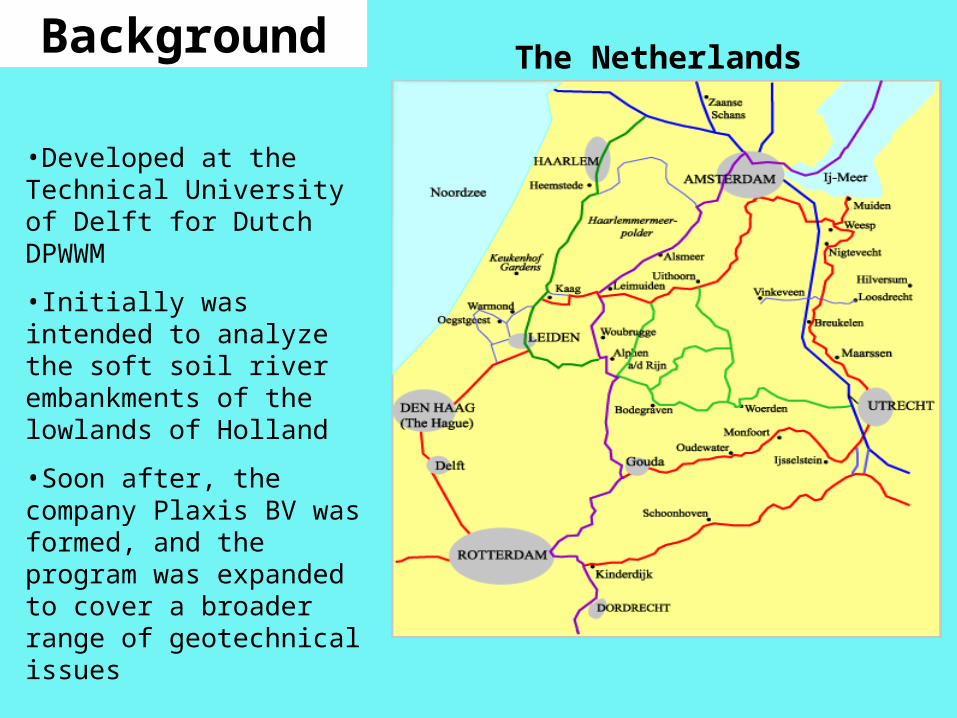
•Developed at the Technical University of Delft for Dutch DPWWM
•Initially was intended to analyze the soft soil river embankments of the lowlands of Holland
•Soon after, the company Plaxis BV was formed, and the program was expanded to cover a broader range of geotechnical issues
The NetherlandsBackground
Getting Started
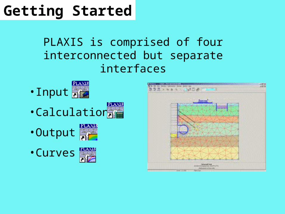
PLAXIS is comprised of four interconnected but separate interfaces
•Input
•Calculations
•Output
•Curves
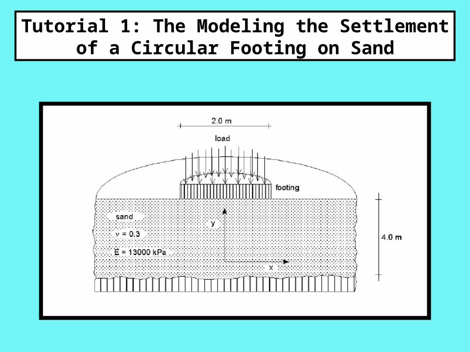
Tutorial 1: The Modeling the Settlement of a Circular Footing on Sand
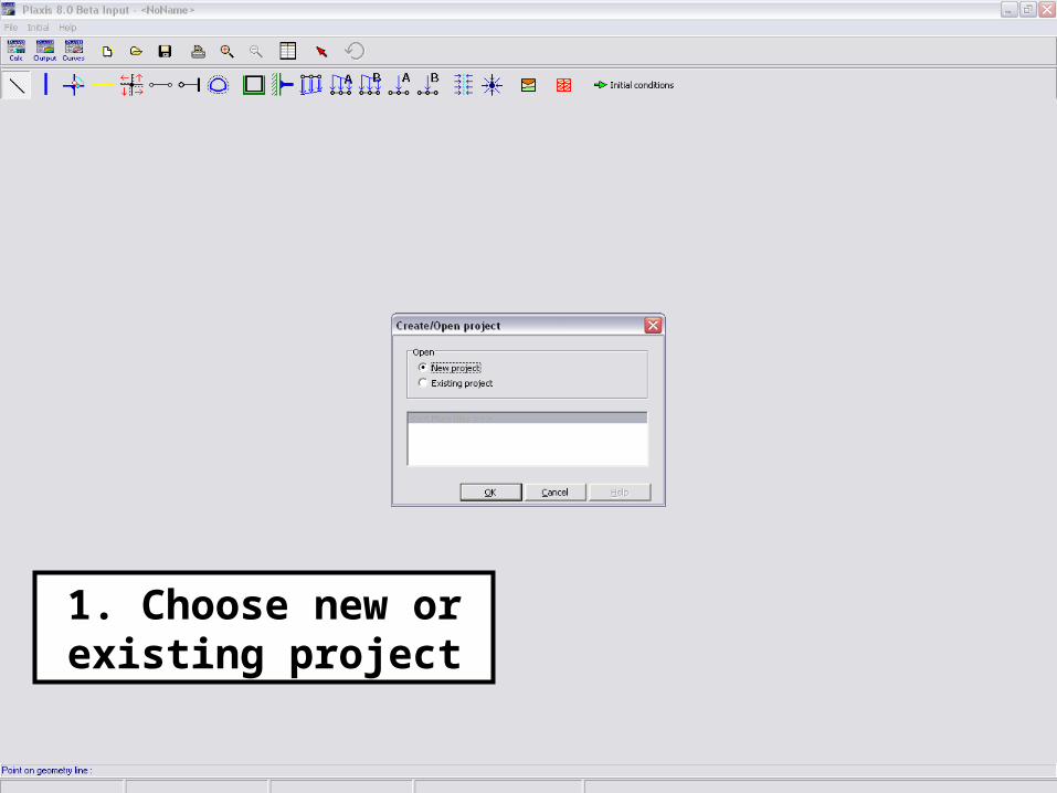
1. Choose new or existing project
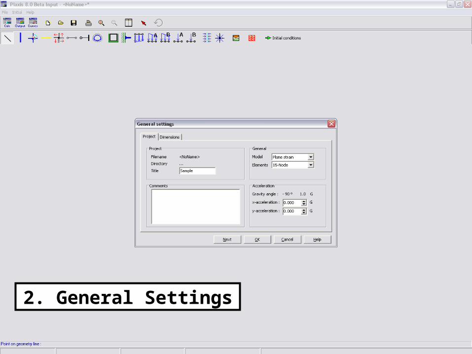
2. General Settings
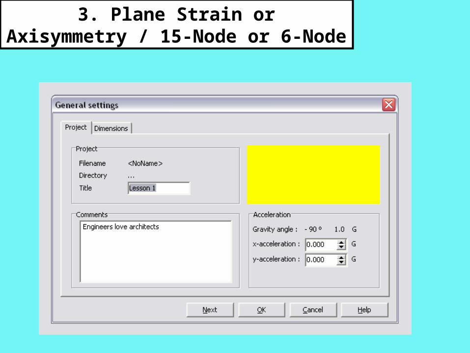
3. Plane Strain or Axisymmetry / 15-Node or 6-Node
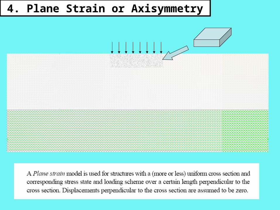
4. Plane Strain or Axisymmetry
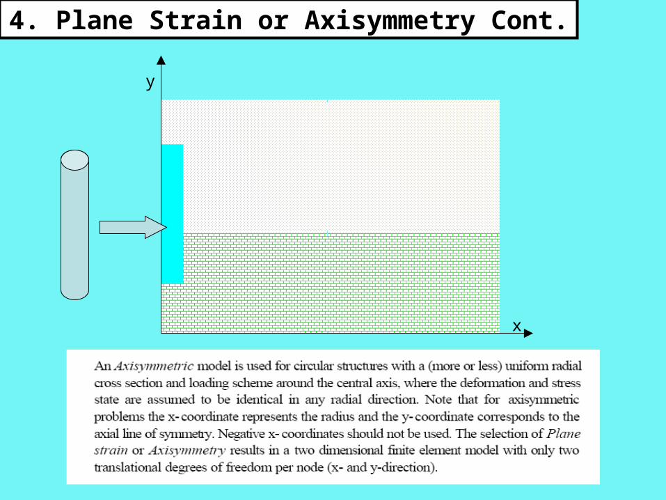
x
y
4. Plane Strain or Axisymmetry Cont.
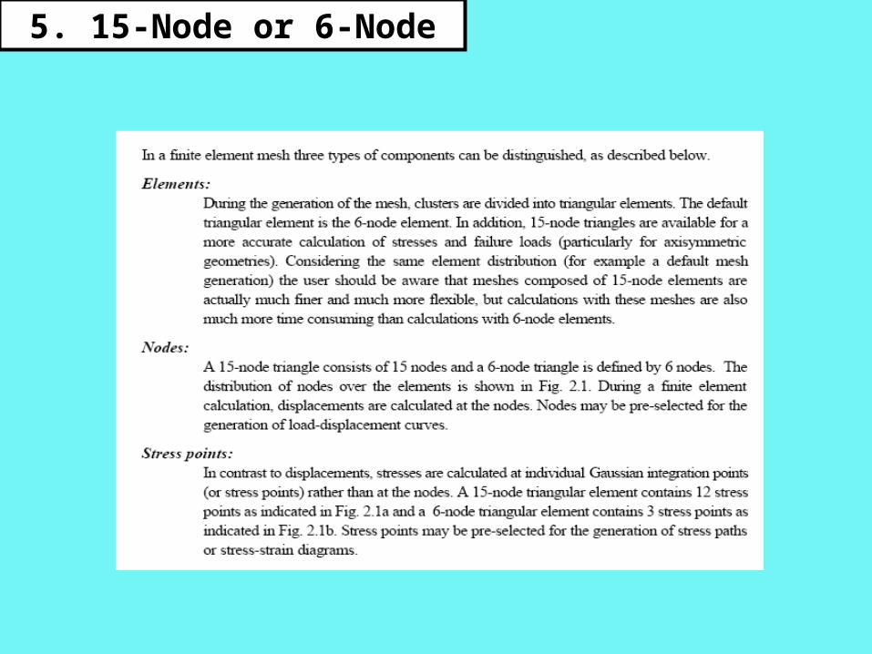
5. 15-Node or 6-Node

5. 15-Node or 6-Node Cont.
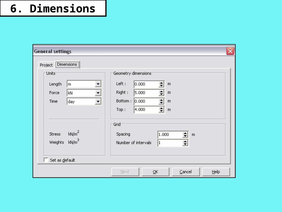
6. Dimensions
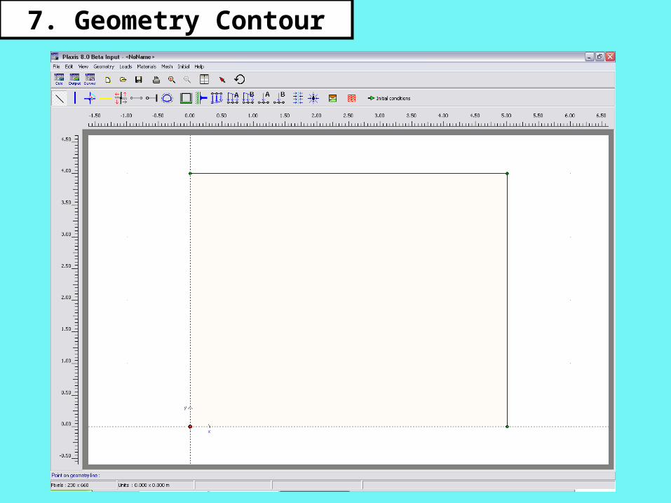
7. Geometry Contour
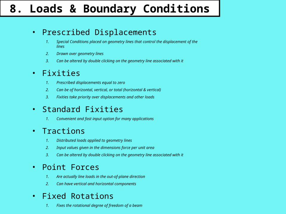
8. Loads & Boundary Conditions
• Prescribed Displacements1. Special Conditions placed on geometry lines that control the
displacement of the lines
2. Drawn over geometry lines
3. Can be altered by double clicking on the geometry line associated with it
• Fixities1. Prescribed displacements equal to zero
2. Can be of horizontal, vertical, or total (horizontal & vertical)
3. Fixities take priority over displacements and other loads
• Standard Fixities1. Convenient and fast input option for many applications
• Tractions1. Distributed loads applied to geometry lines
2. Input values given in the dimensions force per unit area
3. Can be altered by double clicking on the geometry line associated with it
• Point Forces1. Are actually line loads in the out-of-plane direction
2. Can have vertical and horizontal components
• Fixed Rotations1. Fixes the rotational degree of freedom of a beam
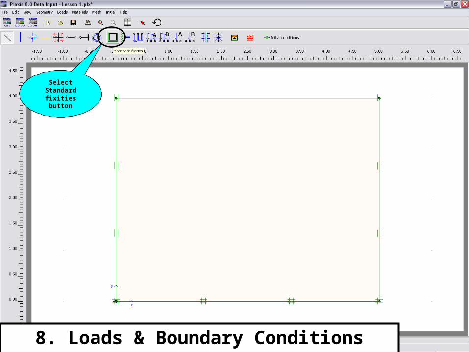
8. Loads & Boundary Conditions cont.
Select Standard fixities button
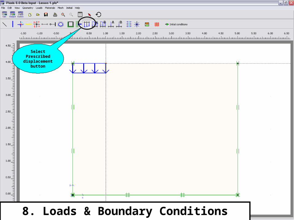
8. Loads & Boundary Conditions cont.
Select Prescribed
displacement button
9. Material Properties
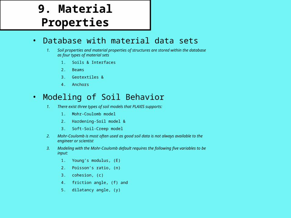
• Database with material data sets1. Soil properties and material properties of structures are stored within the
database as four types of material sets
1. Soils & Interfaces
2. Beams
3. Geotextiles &
4. Anchors
• Modeling of Soil Behavior1. There exist three types of soil models that PLAXIS supports:
1. Mohr-Coulomb model
2. Hardening-Soil model &
3. Soft-Soil-Creep model
2. Mohr-Coulomb is most often used as good soil data is not always available to the engineer or scientist
3. Modeling with the Mohr-Coulomb default requires the following five variables to be input:
1. Young’s modulus, (E)
2. Poisson’s ratio, (n)
3. cohesion, (c)
4. friction angle, (f) and
5. dilatancy angle, (y)
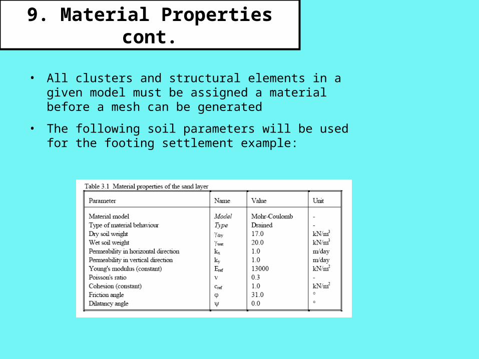
• All clusters and structural elements in a given model must be assigned a material before a mesh can be generated
• The following soil parameters will be used for the footing settlement example:
9. Material Properties cont.
9. Material Properties cont.
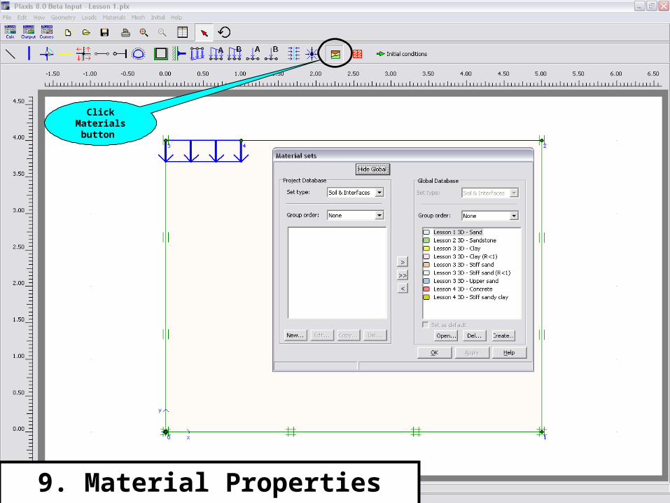
Click Materialsbutton
9. Material Properties cont.
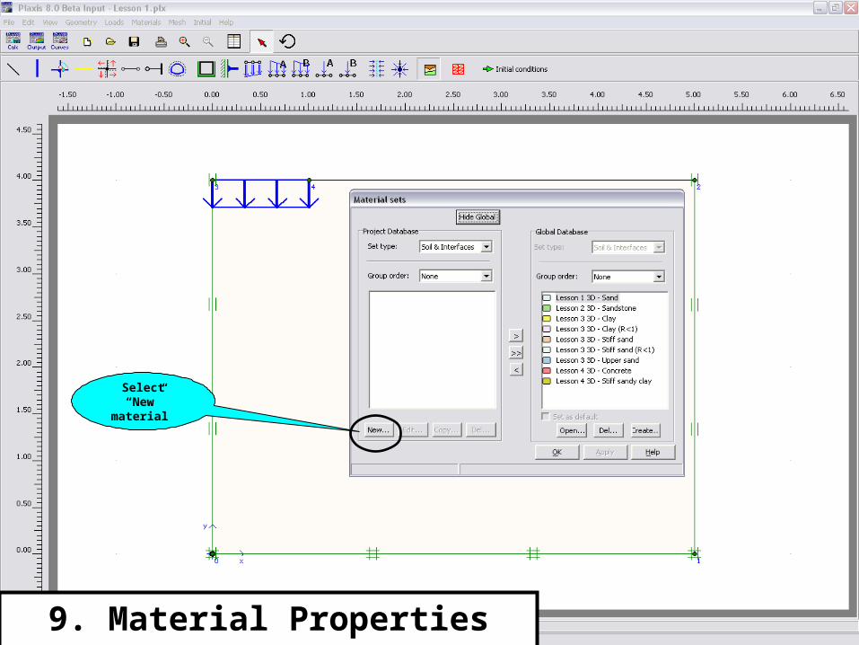
Select “New”
material
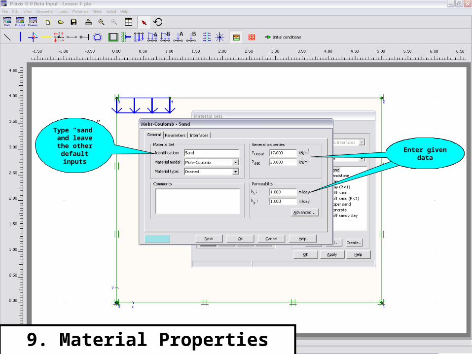
9. Material Properties cont.
Type “sand” and leave the
other default inputs
Select “New”
material
Enter given data
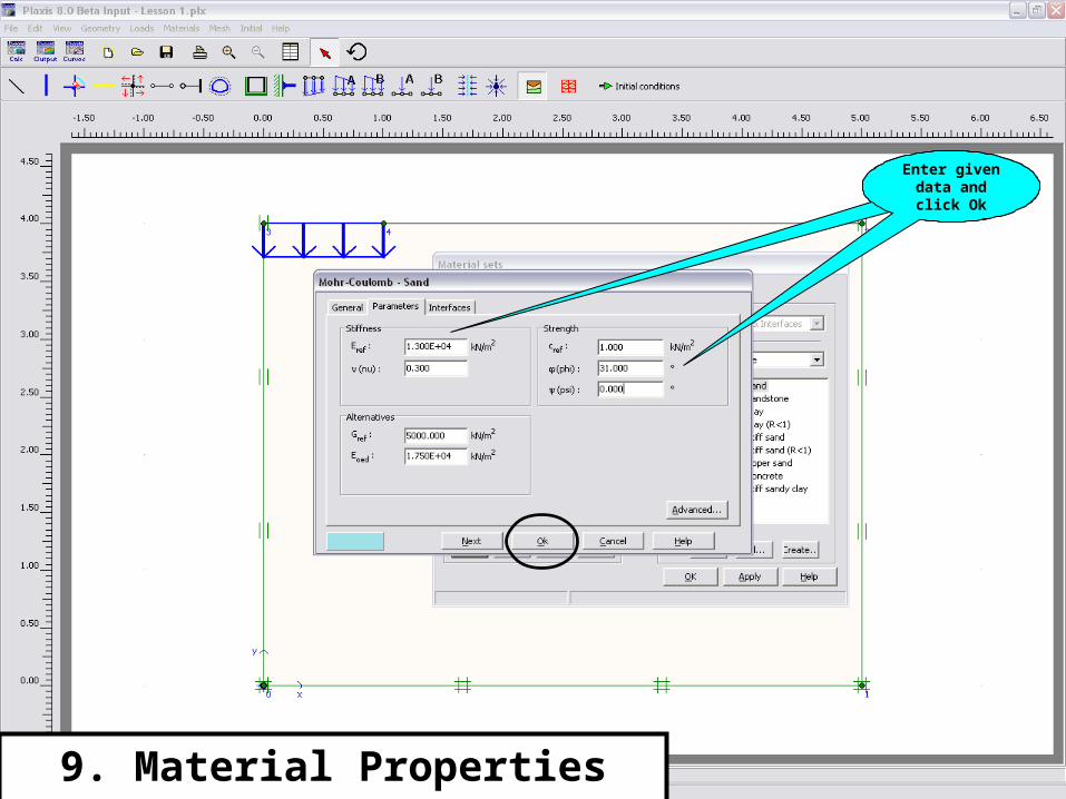
9. Material Properties cont.
Select “New”
material
Enter given data and click Ok
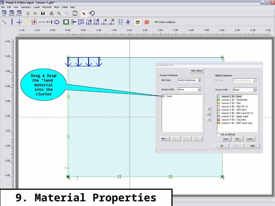
Drag & Drop the “Sand”
material into the cluster
9. Material Properties cont.
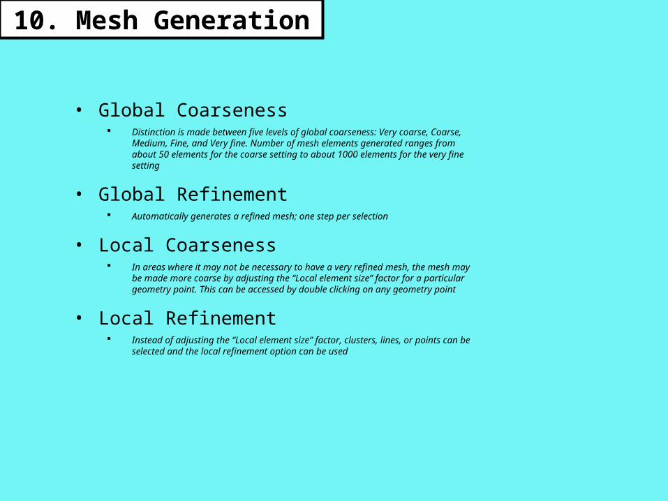
10. Mesh Generation
• Global Coarseness Distinction is made between five levels of global coarseness: Very coarse,
Coarse, Medium, Fine, and Very fine. Number of mesh elements generated ranges from about 50 elements for the coarse setting to about 1000 elements for the very fine setting
• Global Refinement Automatically generates a refined mesh; one step per selection
• Local Coarseness In areas where it may not be necessary to have a very refined mesh, the
mesh may be made more coarse by adjusting the “Local element size” factor for a particular geometry point. This can be accessed by double clicking on any geometry point
• Local Refinement Instead of adjusting the “Local element size” factor, clusters, lines, or
points can be selected and the local refinement option can be used
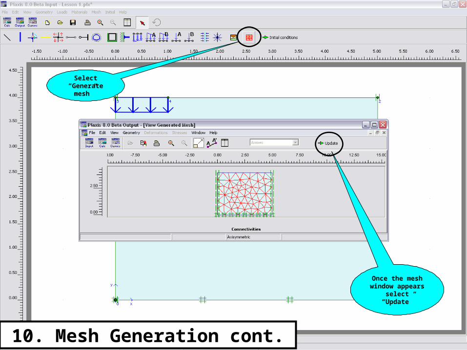
10. Mesh Generation cont.
Select “Generate
mesh”
Once the mesh window
appears select “Update”
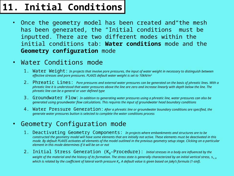
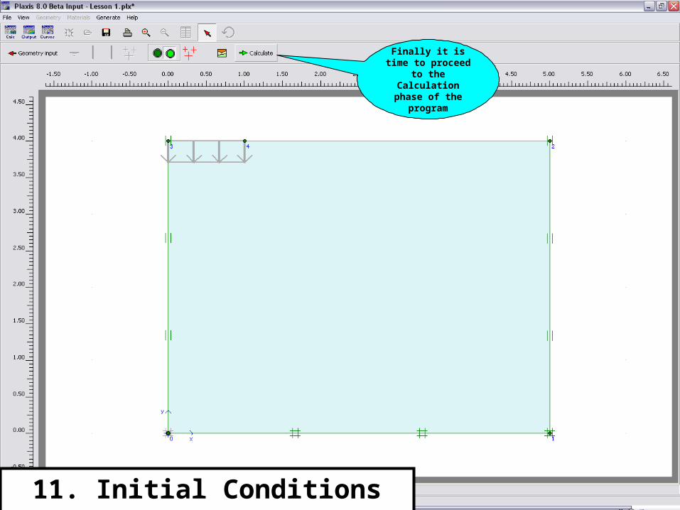
11. Initial Conditions
• Once the geometry model has been created and the mesh has been generated, the “Initial conditions” must be inputted. There are two different modes within the initial conditions tab: Water conditions mode and the Geometry configuration mode
• Water Conditions mode1. Water Weight: In projects that involve pore pressures, the input of water weight in necessary to distinguish
between effective stresses and pore pressures. PLAXIS default water weight is set to 10kN/m3
2. Phreatic Lines: Pore pressures and external water pressures can be generated on the basis of phreatic lines. With a phreatic line it is understood that water pressures above the line are zero and increase linearly with depth below the line. The phreatic line can be a general or user defined type
3. Groundwater Flow: In addition to generating water pressures using a phreatic line, water pressures can also be generated using groundwater flow calculations. This requires the input of groundwater head boundary conditions
4. Water Pressure Generation: After a phreatic line or groundwater boundary conditions are specified, the generate water pressures button is selected to complete the water conditions process
• Geometry Configuration mode1. Deactivating Geometry Components: In projects where embankments and structures are to be
constructed the geometry model will have some elements that are initially not active. These elements must be deactivated in this mode. By default PLAXIS activates all elements of the model outlined in the previous geometry setup stage. Clicking on a particular element in this mode determines if it will be on or not
2. Initial Stress Generation (K0-Procedure): Initial stresses in a body are influenced by the weight of
the material and the history of its formation. The stress state is generally characterized by an initial vertical stress, sn,0 which is related by the coefficient of lateral earth pressure K0. A default value is given based on Jaky’s formula (1-sinf).
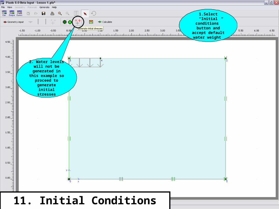
1.Select “Initial conditions” button and
accept default water weight
11. Initial Conditions cont.
2. Water levels will not be
generated in this example so
proceed to generate initial
stresses

Accept default K0 parameters
11. Initial Conditions cont.
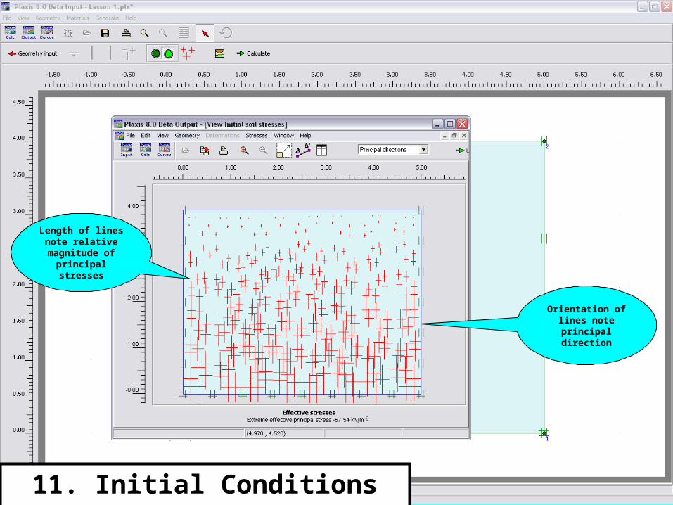
Length of lines note relative magnitude of
principal stresses
11. Initial Conditions cont.
Orientation of lines note principal direction
11. Initial Conditions cont.
Finally it is time to proceed to
the Calculation phase of the
program

Questions?