Platform positioning during MDT construction Tool for the platform positioning Ph. Schune J.-Ch....
7
Platform positioning during MDT construction Tool for the platform positioning Ph. Schune J.-Ch. Barrière PRAXIAL ALIGNMENT SYSTEM (barrel) positio ning calibration calibration of PRAXIAL part TLAS Align. PDR h. Schune (Saclay) QA/QC: in production site and at the CERN X-ray tomograph calibration of AXIAL part conclusion PRAXIAL active optical elements 1
-
Upload
hilary-james -
Category
Documents
-
view
220 -
download
0
Transcript of Platform positioning during MDT construction Tool for the platform positioning Ph. Schune J.-Ch....

Platform positioning duringMDT construction
Tool for the platformpositioning
Ph.
Sch
une
J.-C
h. B
arri
ère
PRAXIAL ALIGNMENT SYSTEM (barrel)po
siti
onin
gca
libr
atio
n
calibration of PRAXIAL part
ATLAS Align. PDRPh. Schune (Saclay)
QA/QC: in production site and at the CERN X-ray tomograph
calibration of AXIAL part
conclusionPRAXIAL activeoptical elements
1

Principle:• The PRAXIAL system is used to unite a layer of chambers (about 6 MDT) to form a single “rigid” layer. It is composed by two systems. The precision on the positioning of both systems are:
±25 m (y,z), ±200 m (x), < 80 rad (x,z), ±200 rad (y).
Goal (for the positioning):• Positioning of the (four) platforms at their nominal position on the MDT
chambers (no position measurement in a database). The calibration of the active optical elements is done elsewhere
Method: • Use four precisely adjusted template squares (precision < 20 m) to hold the platform at their nominal position, during the glue curing, w.r.t. the end plugs (2 pts) and the outer tube surface (or on the jig, BOS only)
at the level of the first comb.
PRAXIAL ALIGNMENT SYSTEM Tool for the platform positioning
PRAXIAL Platform
Template squarescalibration (CMM)
ATLAS Align. PDRPh. Schune (Saclay)
J.-Ch.B., C.G. andH.v.d.G. presentations
red = proj.blue = praxialgreen= ref.
2
Y
Z
Atlas axis
X 3D view.

The platform is glued at its nominal position during the glue curing of the first MDT layer.
ATLAS Align. PDRPh. Schune (Saclay)
Flat surface on MDT end plugs
Half sphere on MDT end plugs
6 adjustable (on CMM) balls for the platform positioning (< 20 m)
Half sphere on the
MDT tube outer surface
(or on the jig, BOS)
Template square
PRAXIAL ALIGNMENT SYSTEM Platform positioning during MDT construction
PRAXIAL platform
template square with its precise positioning sphere
end-plug of the tube(circularity: < 20 m)
jig
glue
Gluing of the platform(detail)
3

ATLAS Align. PDRPh. Schune (Saclay) PRAXIAL ALIGNMENT SYSTEM
QA/QC: in production site and at the CERN X-ray tomographGoal:Control the chamber mechanical deformation (sag angular displacement of the platform) coming from the assembly of the different layer (e.g. BIS-Thessaloniki).
Method:Use four control tower (one on each platform) each equipped with 4 LED and 2 CCD ( two crossed BCAM).The towers calibrate (relative) platform position: x, y and z.Special software distributed to all labs.
mra
d
Rotation angle vs step (BIS-0): sag. of the chamber
Calibration benchof the tools (in each
lab., if possible)
CCD image of the 2LED from the opposite tower: ~ 0.5 pixel < 100 rad
J.B.
Control tower in position
distance adjusted to ± 2 mm
CCD LEDs
marble table
Platform angle ~ (X/Y(pixel) - X0/Y0) * pixel_size / f
4

ATLAS Align. PDRPh. Schune (Saclay) PRAXIAL ALIGNMENT SYSTEM
QA/QC: in production site and at the CERN X-ray tomograph
4 W/Au wires(Ø = 100 m)
microscope
spheres for the positioning
2D table
support only needed during the calibration
X
Z
Y
After the calibration (“optical CMM”) of the four masks, we know the wires and spheres position with the following precision: wires (4):
• = 100 m 2 m• straightness < 5 m
positioning spheres (6):• = 8 mm 5 m
RO
sid
e
MASK 3MASK 1
MASK 6MASK 2
BML chamber
HV
sid
e
Optical CMM
Chamber on tomograph (top view)
Goal:Verify the final platform position w.r.t. to MDT wires.
Method:Use four masks (one on each platform) equipped with wires. The masks wires are precisely located w.r.t. to the positioning spheres (< 10 m). Four X-ray tomo scans ( ) are needed for measuring the platforms position. These masks calibrate absolute platforms position: x, y, z and y, z.
Mask with its4 wires
5
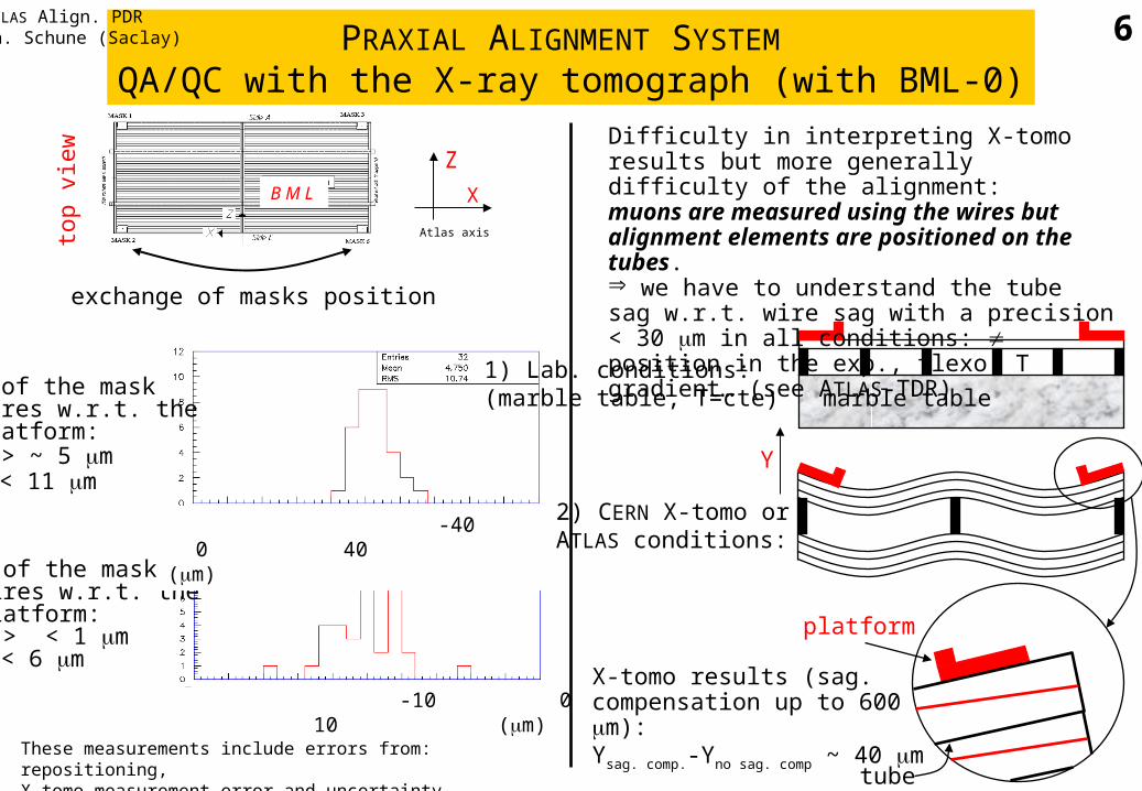
Y of the mask wires w.r.t. the platform:< > ~ 5 m< 11 m
Z of the mask wires w.r.t. the platform:< > < 1 m< 6 m
These measurements include errors from: repositioning, X-tomo measurement error and uncertainty from local frame
-40 0 40 (m)
-10 0 10 (m)
PRAXIAL ALIGNMENT SYSTEM QA/QC with the X-ray tomograph (with BML-0)
top
view
B M L
Z
X
Atlas axis
ATLAS Align. PDRPh. Schune (Saclay) 6
exchange of masks position
Difficulty in interpreting X-tomo results but more generally difficulty of the alignment:muons are measured using the wires but alignment elements are positioned on the tubes. we have to understand the tube sag w.r.t. wire sag with a precision < 30 m in all conditions: position in the exp., flexo, T gradient… (see ATLAS-TDR)
platform
2) CERN X-tomo or ATLAS conditions:
1) Lab. conditions: (marble table, T=cte)
X-tomo results (sag. compensation up to 600 m):Ysag. comp.-Yno sag. comp ~ 40 m
marble table
tube
Y

PRAXIAL ALIGNMENT SYSTEMPositioning precision
Positioning tool (CMM): < 20 m
Platform quality + repeatability of the positioning: ~ 10 m
(special tools will be designed/made to help for the positioning)
End-plug circularity: < 20 m
Mask for X-tomo (absolute): trans.< 10 m and rot.< 100 rad
(first complete measurement: BML-1, April 2001)
optical sensor calibration J.-Ch. B. presentation
Pos
itio
ning
Con
trol
Control tower (relative angular movement): < 100 rad
ATLAS Align. PDRPh. Schune (Saclay) 7