Plate Fin Heat Ex Changers
16
Looking Inside... Plate-Fin versus Coil-Wound Heat Exchangers
-
Upload
capricorno4694 -
Category
Documents
-
view
226 -
download
0
Transcript of Plate Fin Heat Ex Changers

8/4/2019 Plate Fin Heat Ex Changers
http://slidepdf.com/reader/full/plate-fin-heat-ex-changers 1/16
Looking Inside...Plate-Fin versusCoil-Wound Heat Exchangers

8/4/2019 Plate Fin Heat Ex Changers
http://slidepdf.com/reader/full/plate-fin-heat-ex-changers 2/16
Contents.
3 Introduction
5 Overview
6 Plate-fn heat exchangers
Features
8 Coil-wound heat exchangers
10 Plate-fn versus coil-wound heat exchangers
Outlook
12 Attachments
Plate-fn heat exchanger structure (Attachment A)
Plate-fn heat exchanger abrication (Attachment B)
Brie comparison (Attachment C)
2

8/4/2019 Plate Fin Heat Ex Changers
http://slidepdf.com/reader/full/plate-fin-heat-ex-changers 3/16
3
Introduction.
The abrication acility o The Linde Group is theEngineering Division, a competent and well-known
supplier o two special types o cryogenic heat ex-changers with an emphasis on LNG production andcryogenic gas processing.
Plate-in as well as coil-wound heat exchangers
are abricated at Linde´s acility in Schalchen. Here,in the south-east o Germany, some 700 highlyqualiied people are employed. Heat exchangers havebeen produced in various orms here or decades.
The speciic technical eatures are outlined anda technical comparison o coil-wound and plate-inheat exchanger is provided.
8/4/2019 Plate Fin Heat Ex Changers
http://slidepdf.com/reader/full/plate-fin-heat-ex-changers 4/16
4
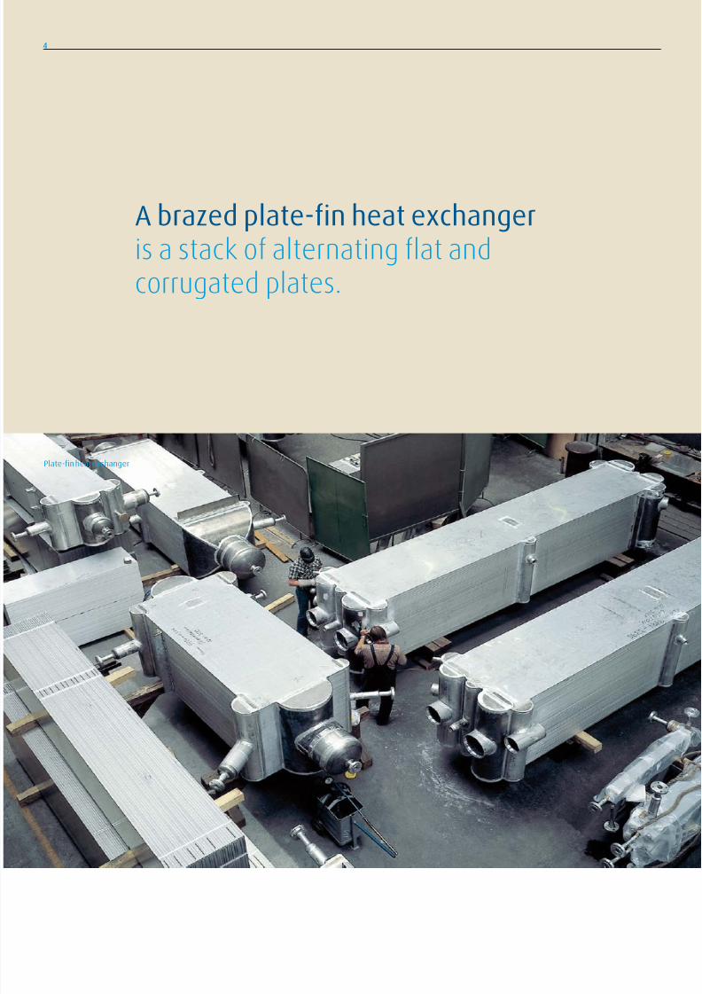
Plate-in heat exchanger
A brazed plate-in heat exchangeris a stack o alternating lat andcorrugated plates.

8/4/2019 Plate Fin Heat Ex Changers
http://slidepdf.com/reader/full/plate-fin-heat-ex-changers 5/16
5
Coil-wound heat exchanger
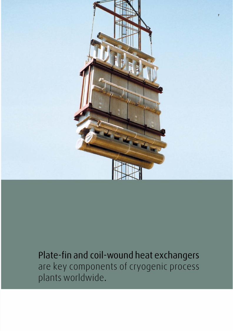
Plate-in and coil-wound heat exchangers
are key components o cryogenic process
plants worldwide. With more than one cen-
tury o experience Linde is one o the majorplayers in this business. Linde is the only
company abricating both types o heat ex-
changers in its own acilities.
As o today, approx. 5000 plate-in heat ex-
changer blocks and some 1000 coil-wound
heat exchangers have been abricated by
Linde or a wide range o applications.
Due to a dearth o available inormation about
plate-in and coil-wound heat exchangers, these
items requently have the status o black boxes
in process plants. The objective o this paper is
to open these black boxes and to have a look
inside.
Furthermore this paper aims to provide a brie
comparison o the two types o heat exchang-
ers in order to amiliarize plant owners with the
typical eatures.
Overview.

8/4/2019 Plate Fin Heat Ex Changers
http://slidepdf.com/reader/full/plate-fin-heat-ex-changers 6/16
Serrated ins
Perorated ins
6
General arrangement
A brazed plate-in heat exchanger is a stack
o alternating lat and corrugated plates. The
corrugations (ins) orm the low channels or
the diverse process luids. Each process stream
occupies a certain number o passages within
the stack. These are collected by hal-pipe
headers and nozzles to single point connections
on the inlet and the outlet o the respective proc-
ess stream. In this way, up to 10 process luids
can exchange heat in only one heat exchanger
block. Fig.1 is a sketch o the various types o
ins.
Materials and design temperature
Usually this type o heat exchanger is madeo aluminium alloys 3003 (blocks) and 5083
(all attachments). It is important to know that
with these standard materials the upper design
temperature is limited to +65°C due to code
requirements.
Fins
In order to meet the required perormance, Linde
can select the appropriate in out o about 50
dierent in types. In general a distinction is
made between perorated ins and serrated ins.
Serrated ins have higher heat transer coei-
cients than perormated ins. However, serrated
ins are more prone to ouling and result in high-
er pressure drop.
Fabrication
In order to bond the loose stack o plates and
ins to a rigid block, vacuum brazing is used. This
sophisticated process means spanning the loose
stack together and heating it in a vacuum ur-
nace up to a temperature o about 600°C. It
should be understood that this temperature is
very near the melting point o the aluminium
base materials. The iller material is clad by roll-
ing on both sides o each parting sheet. The ins
however are pure aluminium alloy without any
cladding. Ater the vacuum brazing the blocks
are completed by welding all the attachments
such as hal-pipe headers, nozzles, support
brackets and liting trunnions to the block.
Please reer to Attachment B on page 13).
Beneits
Vacuum brazed plate-in heat exchangers made
o aluminium oer a number o advantages:
They are extremely compact due to the use o
aluminium and highly eicient ins. The “heating
surace density“ can be greater than 1000 m²/m³.
Thus this type o heat exchanger is perectly
suitable or installations which require compact
design. The wide selection o heat transer ins
combines high heat transer rates with low pres-
sure drops (i.e. low energy consumption) intailor made heat exchangers. The ability to com-
bine up to 10 process streams in only one heat
exchanger system can eliminate the need or
multiple heat exchanger arrangements and the
interconnecting piping. The use o high strength
aluminium alloy results in light weight units thus
reducing drastically the oundation and support
requirements.
Knowing the limits
Knowing the technical advantages as well as the
corresponding limits o a plate-in heat exchanger
helps to make correct procurement decisions and
to avoid later disappointments and diiculties.
Due to their arrangement as a large and rigid
aluminium block, and considering the small gaps
inside, this type o heat exchanger cannot be
recommended or cases o operation such as :
– high temperature gradients(i.e. thermal shocks)
– high temperature dierences between
the cold and the warm process streams
– process streams containing particles or
suseptible to severe ouling
– cyclic loads (pressure and temperature)
– service which is known to be corrosive
to aluminium
Naturally Linde will advise a potential user
whether a plate-in heat exchanger is recom-
mendable or a speciied application or not.
Plate-in heat exchangers.
Fig.1
8/4/2019 Plate Fin Heat Ex Changers
http://slidepdf.com/reader/full/plate-fin-heat-ex-changers 7/16
7
Plate-in and coil-wound heat exchangersare key components o cryogenic processplants worldwide.

8/4/2019 Plate Fin Heat Ex Changers
http://slidepdf.com/reader/full/plate-fin-heat-ex-changers 8/16
History
Coil-wound heat exchangers have been manu-
actured by Linde since the early days, when Carl
von Linde liqueied air on an industrial scale or
the irst time in Munich, Germany in May 1885.
Improvements in aluminium welding technology
in the late 1950s made it possible to change
rom rather expensive and heavy copper to the
cheaper and lighter all-aluminium-designs.
More than one thousand coil-wound heat ex-
changers or various application and in diverse
materials such as stainless steel, special alloys,
copper and aluminium, with heating suraces
o up to 20,000 m² and unit weights o up to
170 metric tons have been abricated since.
General arrangement
A coil-wound heat exchanger is, in general, a
tubular heat exchanger; however, the bundle
does not consist o not using a straight tubes.
Tubes o relatively long length and small
diameter are wound in alternating directions
around a centre pipe (the so called mandrel).
In parallel a pressure vessel shell is prepared
and the complete tube bundle is inserted. All
single tubes start and terminate in tubesheets
which are integral parts o the pressure vessel
shell.
Features o Linde‘s coil-wound heat
exchangers in LNG baseload plants
Flexible tube bundle
Due to the lexible tube bundle arrangement
these heat exchangers can bear temperature
gradients and dierences clearly exceeding the
limits o other heat exchanger types (e.g. plate-
in heat exchangers).
No bundle sagging
Over the speciied design lie no considerable
bundle sagging is to be expected. This is due
to Linde´s sophisticated bundle support system.
Tube bundle beore insertion into thepressure vessel shell
8
Coil-wound heat exchangers.

8/4/2019 Plate Fin Heat Ex Changers
http://slidepdf.com/reader/full/plate-fin-heat-ex-changers 9/16
Complete coil-wound heat exchangers during
installation on site
The tube bundles are designed and abricated to be
vibration-proo and sel-draining.
9
Best liquid distribution
Optimal liquid distribution o the shell side
2-phase stream over the whole cross section
o the bundle is achieved by internal phase sepa-
ration and special liquid distribution systems.
The latest liquid distributor design minimises the
liquid hold-up on top o the bundles, thus reduc-ing negative thermal eects during trip cases.
Tube arrangement
The tube bundles are designed and abricated
to be vibration-proo and sel-draining.
Tailor made materials
The pressure vessel shell is typically made o
aluminium alloy 5083. For the tubes, special
aluminium alloy and a non-standard (but ap-
proved) abrication procedure is used or tube
manuacturing.
Supporting the tube bundle
Each tube bundle is reely suspended rom a
special support system on top o each bundle.
Thus shrinkage and expansion o the tube bun-
dles due to rapid temperature changes during
start-up or shut-down occur with minimum
stresses between the tube bundle and the shell.The support system is designed to carry the
weight o the tube bundles, the luids and the
pressure drops.
Eliminating by-pass streams
Each tube bundle is wrapped into a “shroud“
which is seal welded on the upper side o the
shell to avoid any rerigerant passing between
the tube bundle and the shell.
In case o tube ailure the leaking tube can be
easily repaired by plugging the concerned tube.
In order to acilitate such repairs and to minimize
the shut-down time the installation o suitable
access holes is oreseen.

8/4/2019 Plate Fin Heat Ex Changers
http://slidepdf.com/reader/full/plate-fin-heat-ex-changers 10/16
10
Attachment C (page 14) provides an overview
o the major dierences between plate-in and
coil-wound heat exchangers. The most impor-
tant eature o the plate-in heat exchanger is
the compact design. The coil-wound heat ex-
changer´s deining characteristic is its intrinsic
robustness.
The extreme compactness o the plate-in
heat exchangers becomes obvious when one
knows that both o the cold boxes1) shown
in this picture are designed or the same per-
ormance. These two cold boxes are installed in
an LNG peak shaving plant in South Arica.
The small coldbox on the let side contains a
plate-in heat exchanger. The much taller cold
box on the right side contains a coil-wound heat
exchanger.
Presently this peak shaving plant is operated
using the coil wound heat exchanger with
outstanding results regarding reliability and
turn-down behaviour.
For LNG baseload applications it is important
to know that typically the coil-wound heat ex-
changers are designed standing “cold side up -
warm side down“. This is another dierence
in comparison with plate-in heat exchangers.
This arrangement allows proper 2-phase distri-
bution o rerigerant vaporizing downwards on
the shell side o a coil-wound heat exchanger.
It is well suited or turndown operation.
A plate-in heat exchanger in similar service
usually vaporizes upwards. It requires a lot o
know-how and experience to design such a
plate-in heat exchanger or turn-down opera-
tion. I the design does not consider this prop-
erly, the vaporization in turn-down can create
luid luctuations causing cyclic thermal and
mechanical stresses.
1) A “cold box“ is understood to be a carbon steel
casing containing various process equipment
like heat exchangers, columns, instrumentation,
all interconnecting piping, etc. The thermal insu-
lation is typically expanded perlite.
Linde cold boxes in a LNG peak shaving plant
Plate-in versuscoil-wound heat exchangers.
8/4/2019 Plate Fin Heat Ex Changers
http://slidepdf.com/reader/full/plate-fin-heat-ex-changers 11/16
11
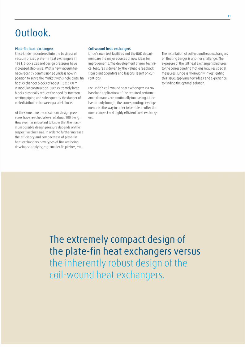
Plate-in heat exchangers
Since Linde has entered into the business o
vacuum brazed plate-in heat exchangers in
1981, block sizes and design pressures have
increased step-wise. With a new vacuum ur-
nace recently commissioned Linde is now in
position to serve the market with single plate-in
heat exchanger blocks o about 1.5 x 3 x 8 m
in modular construction. Such extremely large
blocks drastically reduce the need or intercon-
necting piping and subsequently the danger o
maledistribution between parallel blocks.
At the same time the maximum design pres-
sures have reached a level o about 100 bar-g.
However it is important to know that the maxi-mum possible design pressure depends on the
respective block size. In order to urther increase
the eiciency and compactness o plate-in
heat exchangers new types o ins are being
developed applying e.g. smaller in pitches, etc.
Coil-wound heat exchangers
Linde‘s own test acilities and the R&D depart-
ment are the major sources o new ideas or
improvements. The development o new techni-
cal eatures is driven by the valuable eedback
rom plant operators and lessons learnt on cur-
rent jobs.
For Linde‘s coil-wound heat exchangers in LNG
baseload applications o the required perorm-
ance demands are continually increasing. Linde
has already brought the corresponding develop-
ments on the way in order to be able to oer the
most compact and highly eicient heat exchang-
ers.
The installation o coil-wound heat exchangers
on loating barges is another challenge. The
exposure o the tall heat exchanger structures
to the corresponding motions requires special
measures. Linde is thoroughly investigating
this issue, applying new ideas and experience
to inding the optimal solution.
The extremely compact design othe plate-in heat exchangers versusthe inherently robust design o thecoil-wound heat exchangers.
Outlook.

8/4/2019 Plate Fin Heat Ex Changers
http://slidepdf.com/reader/full/plate-fin-heat-ex-changers 12/16
With a new vacuum urnace recently commissioned,Linde is now in position to serve the market withsingle plate-in heat exchanger blocks o about1.5 x 3 x 8 m in modular construction.
Plate-fn heat exchanger structure (Attachment A)
Block
Header
NozzleWidth
Stacking height
Length
Passage outlet
Cover sheet
Parting sheet
Heat transer fn
Distribution fn
Side bar
End bar
12
1
2
34
5
6
7
8
9
10
11
12
13

8/4/2019 Plate Fin Heat Ex Changers
http://slidepdf.com/reader/full/plate-fin-heat-ex-changers 13/16
13
Parting sheets, cover sheets Fins
Header and nozzles
Side bars
Raw materials
Measuring, cutting
Washing
Raw materials
Stamping,
measuring, cutting
Washing
Stacking
Vaccumbrazing urnace
Raw materials
Measuring, cutting
Washing
Raw materials Raw materials Raw materials
Measuring, cutting Measuring, cutting
Assembly
Completion o heat exchanger
Testing
13

8/4/2019 Plate Fin Heat Ex Changers
http://slidepdf.com/reader/full/plate-fin-heat-ex-changers 14/16
14
Brie comparison (Attachment C) Plate-in heat exchanger piped in cold box
Plate-fn heat exchanger Coil-wound heat exchanger
FeaturesExtremely compact
Up to ~10 streams
Extremely robust
Compact
Fluids Very cleanNon-corrosive
Heating surace 300 - 1000 m²/m³ 50 - 150 m²/m³
Materials Al Al, SS, CS etc.
Design temperatures -269°C to +65°C all
Applicationssmooth operation
limited installation space
temp. gradients
temp. dierences
Prices
~25 - 35 %
(without maniolds / steel casings) 100 %

8/4/2019 Plate Fin Heat Ex Changers
http://slidepdf.com/reader/full/plate-fin-heat-ex-changers 15/16
15
With more than one century o experience,Linde is one o the major players in this businessand the only company abricating both types oheat exchangers in its own acilities.
Coil-wound heat exchanger

8/4/2019 Plate Fin Heat Ex Changers
http://slidepdf.com/reader/full/plate-fin-heat-ex-changers 16/16
Engineering Division head oice:
Linde AG
Engineering Division
Pullach, Germany
Phone: +49.(0)89.7445-0
Fax: +49.(0)89.7445-4908
L N G / 3 . 2 . e
/ 0 9
Linde´s Engineering Division continuously develops extensive process engineering know-how in the planning,
project management and construction o turnkey industrial plants.
The range o products comprises:
− Petrochemical plants
− LNG and natural gas processing plants
− Synthesis gas plants
− Hydrogen plants
− Gas processing plants
− Adsorption plants
− Air separation plants
− Cryogenic plants
− Biotechnological plants
− Furnaces or petrochemical plants and refneries
Linde and its subsidiaries manuacture:
− Packaged units, cold boxes
− Coil-wound heat exchangers
− Plate-fn heat exchangers
− Cryogenic standard tanks
− Air heated vaporizers
− Spiral-welded aluminium pipes
Engineering Division headquarters:
Linde AG
E i i Di i i D C l Li d St 6 14 82049 P ll h G
More than 3,800 plants worldwide document the leading position of the Engineering Division in international plant construction.
Engineering Division
Schalchen PlantTacherting, Germany
Phone +49.8621.85-0
Fax +49.8621.85-6620
Linde-KCA-Dresden GmbH
Dresden, Germany
Phone +49.351.250-30
Fax +49.351.250-4800
Selas-Linde GmbH
Pullach, Germany
Phone +49.89.7447-470
Fax +49.89.7447-4717
Cryostar SAS
Hésingue, France
Phone +33.389.70-2727
Fax +33.389.70-2777
Linde CryoPlants Ltd.
Aldershot, Great Britain
Phone +44.1.252.3313-51
Fax +44.1.252.3430-62
Linde Impianti Italia S.p.A.
Rome, ItalyPhone +39.066.5613-1
Fax +39.066.5613-200
Linde Kryotechnik AG
Pungen, Switzerland
Phone +41.52.3040-555
Fax +41.52.3040-550
Cryo AB
Göteborg, Sweden
Phone +46.3164-6800
Fax +46.3164-2220
Linde Process Plants, Inc.
Tulsa, OK, U.S.A.
Phone +1.918.4771-200
Fax +1.918.4771-100
Selas Fluid Processing Corp.
Blue Bell, PA, U.S.A.
Phone +1.610.834-0300
Fax +1.610.834-0473
Linde Engenharia do Brasil Ltda.
Rio de Janeiro, BrazilPhone +55.21.3545-2255
Fax +55.21.3545-2257
Linde Process Plants (Pty.) Ltd.
Johannesburg, South Arica
Phone +27.11.490-0513
Fax +27.11.490-0412
Linde-KCA Russia Branch
Moscow, Russia
Phone +7.495.646-5242
Fax +7.795.646-5243
Linde Arabian Contracting Co. Ltd.
Riyadh, Kingdom o Saudi Arabia
Phone +966.1.419-1193
Fax +966.1.419-1384
Linde Engineering Middle East LLC
Abu Dhabi, United Arab Emirates
Phone +971.2.4477-631
Fax +971.2.4475-953
Linde Engineering India Pvt. Ltd.
Vadodara, Gujarat, IndiaPhone +91.265.3056-789
Fax +91.265.2335-213
Linde Engineerig Far East, Ltd.
Seoul, South Korea
Phone +82.2789-6697
Fax +82.2789-6698
Linde Engineering Division
Bangkok, Thailand
Phone +66.2636-1998
Fax +66.2636-1999
Linde Engineering Co. Ltd.
Dalian, P.R. o China
Phone +86.411.39538-800
Fax +86.411.39538-855
Linde Engineering Co. Ltd.
Hangzhou, P.R. o China
Phone +86.571.87858-222
Fax +86.571.87858-200
Linde Engineering Division
Beijing Representative OiceBeijing, P.R. o China
Phone +86.10.6437-7014
Fax +86.10.6437-6718
Linde AG Taiwan Branch
Engineering Division
Taipei, Taiwan
Phone +886.2.2786-3131
Fax +886.2.2652-5871
Linde Australia Pty. Ltd.
Chatswood N.S.W., Australia
Phone +61.29411-4111
Fax +61.29411-1470
Designing Processes- Constructing Plants.