plasma water treatment - PlasTEP
91
PLASMA FOR WATER TREATMENT Mirosław Dors Part-financed by the European Union (European Regional Development Fund) Centre for Plasma and Laser Engineering The Szewalski Institute of Fluid-Flow Machinery Polish Academy of Sciences Gdaosk, Poland 9.00 – 10.30 11.00 – 12.30
Transcript of plasma water treatment - PlasTEP

PLASMA FOR WATER TREATMENT
Mirosław Dors
Part-financed by the European Union(European Regional Development Fund)
Centre for Plasma and Laser EngineeringThe Szewalski Institute of Fluid-Flow Machinery
Polish Academy of SciencesGdaosk, Poland
9.00 – 10.3011.00 – 12.30

Outline
• Plasma technologies for water cleaning
– Plasma sources for water treatment
• Types of electrical discharges used for water treatment
– Discharges in gas
– Discharges in water (electrohydraulic discharges)
• Reactors
• Diagnostics
– Physics of electrohydraulic discharges
• Plasma processes in water cleaning technologies
– Plasma processes and plasma-induced processes in destruction of organic compounds and microorganisms
• Chemical reactions
• Biocidal effects
• Comparison to other water treatment technologies
Prof. Mirosław Dors, [email protected] 2
3
Plasma technologies for water cleaning
Remote
Indirect
Direct
UV,
electron beam
Ozone
Electrical discharges in water
Plasma
injectionElectrical discharges above water
Different approach

Plasma technologies for water treatment - Remote
Ozonation – fully commercialized method
• Ozone is generated in a Dielectric Barrier Discharge
• Absorption of ozone in water
• Used in drinking water plants
• Ballast water management
NK-O3 Blue Ballast System, USA/Korea
“Alternative Disinfectants and Oxidants Guidance Manual,“ United States Environmental Protection Agency, 1999
4

Plasma technologies for water treatment - Indirect
UV sources
• LP mercury vapor lamps• Low-pressure high-output (LPHO)
mercury vapor lamps• MP mercury vapor lamps• Electrode-less mercury vapor lamps
• Metal halide lamps• Xenon lamps (pulsed UV)• Eximer lamps• UV lasers• Light emitting diodes (LEDs)
Efficiency means electrical to germicidal UV conversion
5

Plasma technologies for water treatment - Indirect
UV irradiation - disadvantages
Mackey et al. (2004)
Linden et al. (2004)
Chang et al. (1985)
6

Plasma technologies for water treatment - Indirect
UV irradiation – reactors and systems
WEDECO UV Systems, USA
ST110P system by SEN Lights Co., Japan
7

Plasma technologies for water treatment - Indirect
Electron beam
8
3-7 MV Electron Beam Water Treatments University of Poitiers (2003-present) & Australia Nuclear Laboratory (1998-2003)
few cm depth water flow
Thermal electron emission from filaments in vacuum then accelerated by a high electric field. Then through Ti or BN thin film by tunnel effects.

Electrical discharges used for water treatment
Discharges in gas phase with liquid electrode – Plasma injection
Prof. Mirosław Dors, [email protected] 9
• needle-to-plate• hollow needle-to-plate
• mesh-to-plate • multiple needle-to-plate
• DC, AC or pulsed corona
• wire-to-plate (pulsed corona only)
• wire-to-cylinder (water layer on the inner wall; pulsed corona only)
HV

Electrical discharges used for water treatment
Discharges in gas phase with liquid electrode – DC glow corona
Prof. Mirosław Dors, [email protected] 10
45 A 50 A
55 A
75 A
65 A
85 A
Hollow needle Hollow needle
Water surface Water surface
20 mm
20 mm
20 mm
200 400 600
0
2
4
6
8
10
12
Curr
ent (m
A)
Time (ns)
200 400 600
0
50
100
150
Pow
er
(W)
Time (ns)
Repetition rate
50 kHz
Pulse energy
29.2 x 10⁻⁶ J

Electrical discharges used for water treatment
Discharges in gas phase with liquid electrode – pulsed corona
Prof. Mirosław Dors, [email protected] 11
Wire-to-plate
Wire-to-cylinder
-2
0
2
4
6
8
10
12
400 500 600 700 800
Volt
age
(kV
)
Time (ns)
-5
0
5
10
15
20
400 500 600 700 800
Curr
ent
(A
)
Time (ns)
-10
20
50
80
110
140
170
400 500 600 700 800
Pow
er (
kW
)
Time (ns)
Repetition rate
250 Hz
Pulse energy
2.76 x 10⁻³ J

Electrical discharges used for water treatment
Gliding Arc
Gas (air, O2, N2) flow: 10-12 L/min. AC supply: 250 W, 100 mA. Water: 400 mLfor 5 min, pH=5.4, 40 S/cm.

Electrical discharges used for water treatment
Direct liquid phase discharges – “electrohydraulic discharges”
Prof. Mirosław Dors, [email protected] 13
• needle-to-plate• hollow needle-to-plate
(gas injected into water)(pulsed corona, pulsed spark discharge)
• needle-to-needle(pulsed arc discharge)
• pinhole(pulsed corona)

Electrical discharges used for water treatment
General physical properties
Prof. Mirosław Dors, [email protected] 14
The reason why the breakdown mechanism in liquids is more complicated than solids and gases is evident:
Liquids are much denser in comparison with gases and do not exhibit the long range order as in most solids.
Additionally, the purity of the liquid, such as dissolved gases which form micro-bubbles in the liquid, plays a significant role in the breakdown process.
0a0
2
0p
R
L
E
TDCV
V – breakdown voltageD – thermal diffusivity of water (ca. 1.5e-7 m2/s)Cpρ – specific heat per unit volumeT0 – temperatureσ0 – water conductivityEa – Arrhenius activation energy for the water conductivityL – breakdown channel lengthR0 – breakdown channel radius

Electrical discharges used for water treatment
Direct liquid phase discharges – pulsed corona and spark
Prof. Mirosław Dors, [email protected] 15
• Inception voltage increases with protrusion length
• Discharge type changes when decreasing distance
• Streamer propagation velocity: 30 000 m/s (2 orders slower than in air)

Electrical discharges used for water treatment
General physical properties
Prof. Mirosław Dors, [email protected] 16
A typical order of magnitude of the local electrical breakdown field of water is 1 MVcm−1 (in the case of microsecond pulsed breakdown), which is more than 30 times the breakdown electrical field of atmospheric pressure air.
For large pulse widths (i.e. several microseconds to dc), especially in high conductive water solutions, the process of breakdown is preceded by vapour formation due to heating by the pre-breakdown current in the liquid.

Electrical discharges used for water treatment
General physical properties
Prof. Mirosław Dors, [email protected] 17
Historically, two principal schools:
The first favours an electron multiplication theory in the liquid - In the past, it was often believed that a current multiplication mechanism such as the development of electron avalanches in gas discharges to initiate breakdown. It is interesting to note that electron avalanches have been observed in cyclohexane. Even more direct correlation between these avalanches and the consequent formation of vapour bubbles in the liquid has been demonstrated. However, electron avalanche processes in bulkwater are nearly negligible due to the usual small high electrical field region near the metal electrode and the large scattering cross sections which make it almost impossible for the electrons to gain sufficient kinetic energy for impact ionization. Additionally, free electrons are generally absent in water because even if they are present, they are quickly solvated within 1 ps time scales. Hence, the probability of free electrons in the bulk water is negligible, although one must be careful not to generalize ideas for different liquids and not to exclude electron avalanche processes without a good motivation.

Electrical discharges used for water treatment
General physical properties
Prof. Mirosław Dors, [email protected] 18
The second school favours a bubble mechanism breakdown theory or more generally a phase change mechanism breakdown theory - a general acceptance is growing that pre-existing bubbles and field enhancement effects in the near electrode region are involved even for nanoseconds voltage pulse widths. Bubbles can pre-exist due to dissolved gases or can be generated by local heating (energy injection from the electrode by pre-breakdown currents) and cavitation.

Electrical discharges used for water treatment
Direct liquid phase discharges – pulsed corona and spark
Prof. Mirosław Dors, [email protected] 19

Electrical discharges used for water treatment
Direct liquid phase discharges – pulsed corona and spark
Prof. Mirosław Dors, [email protected] 20
Corona discharge Spark discharge

Electrical discharges used for water treatment
Direct liquid phase discharges – pulsed corona – gas production
Prof. Mirosław Dors, [email protected] 21

Electrical discharges used for water treatment
Direct liquid phase discharges – pulsed corona – gas production
Prof. Mirosław Dors, [email protected] 22

Electrical discharges used for water treatment
Discharge development
Prof. Mirosław Dors, [email protected] 23
Electrical breakdown is generally defined as the moment when a conductive plasma channel forms an electrical connection between the two metal electrodes inside the liquid. This leads to the formation of a spark or arc. A time lag between application of the high voltage and breakdown is always observed.
This time lag consists of three successive steps: • initiation phase or streamer inception, • streamer propagation phase,• spark and arc phase.

Electrical discharges used for water treatment
Streamer propagation mechanisms
Prof. Mirosław Dors, [email protected] 24
Different streamer modes are observed depending on polarity of the powered electrode and the pulse width and amplitude of the applied voltage pulse.
At first a bushlike hemispherical primary streamer (PS) can be observed showing 100–200 filaments.
Then, a fast secondary streamer (SS) appears above a certain threshold voltage (which depends on the geometry of the setup) and can be considerably longer.

Electrical discharges used for water treatment
Streamer propagation mechanisms
Prof. Mirosław Dors, [email protected] 25
1. Primary streamer (subsonic streamer):• low electron density, • low temperature,• low pressure.• its propagation mechanism: series of current pulses and electron avalanches
in successive vapour bubbles,• appear at low amplitude voltage pulses often filling a hemisphere with a size
of a few hundred micrometres (at least for positive streamers) or have a bush-like shape (negative streamers have many short side branches and are shorter in length than positive streamers. Bubble production during the discharge is also much lower for negative voltages than for positive ones under the same conditions).
• propagation velocity of 100ms−1 to a few km s−1

Electrical discharges used for water treatment
Streamer propagation mechanisms
Prof. Mirosław Dors, [email protected] 26
2. Secondary streamer:• high electron density,• high temperature,• high pressure,• its propagation mechanism: field induced dissociation and ionization of
molecules in the bulk liquid, • propagation velocity in the range 10–100 km s−1.

Electrical discharges used for water treatment
Prof. Mirosław Dors, [email protected] 27
Zoom on the current waveform, (0) beginning of the applied voltage pulse, (1) initiation (or pre-initiation) current due to conductivity of water ∼300mA here, (2) current ramp of the plasma primary positive streamer ∼50 mA, (3) current increase of the secondary positive streamer ∼1A, (4) reilluminations (7μS cm−1, 40 kV)
Streamer propagation – current waveform

Electrical discharges used for water treatment
Prof. Mirosław Dors, [email protected] 28
Current waveform in distilled water, (0) stray displacement current, (1) pre-initiation current due to water conductivity, (3) large pulse of the secondary positive mode followed by (4) reillumination spikes with decaying amplitude (4 cm gap, 40 kV)
Streamer propagation – current waveform

Electrical discharges used for water treatment
Prof. Mirosław Dors, [email protected] 29
Current waveform in 500 μS cm−1 water, there are no reillumination spikes, (1) initiation current, (3) propagation, (4) decay; there is a large current even when the discharge has stopped propagating and just decays according to the voltage pulse decay (4 cm gap, 40 kV).
Streamer propagation – current waveform
Transition to spark: when the plasma filament reaches the opposite plane electrode a thermalization return stroke propagates back to the pin electrode (2n gate, 4μs delay, distilled water, 40 kV).

Electrical discharges used for water treatment
Direct liquid phase discharges – pulsed corona – conductivity
Prof. Mirosław Dors, [email protected] 30
In the pulsed corona the current is mostly transferred by ions. In water of high conductivity:
large current
faster compensation of space charge
streamer length shortening
higher power density in the channel
higher plasma temperature, UV and acoustic waves

Electrical discharges used for water treatment
Direct liquid phase discharges – pulsed corona – conductivity
Prof. Mirosław Dors, [email protected] 31
0,0
0,5
1,0
1,5
2,0
0 100 200 300 400
0
10
20
30
40
Cu
rrent (A
)
Voltage (
kV
)
Time (s)
1 S/cm 200 S/cm 600 S/cm
0
10
20
30
40
50
0 5 10 15 20
0
10
20
30
40
Cu
rrent (A
)
Voltage (
kV
)
Time (s)
0
10
20
30
40
50
0 5 10 15 20
0
10
20
30
40
Curr
ent (A
)
Voltage (
kV
)
Time (s)
FWHM = 36 s(voltage pulse)
FWHM = 1.2 s(voltage pulse)
FWHM = 0.8 s(voltage pulse)
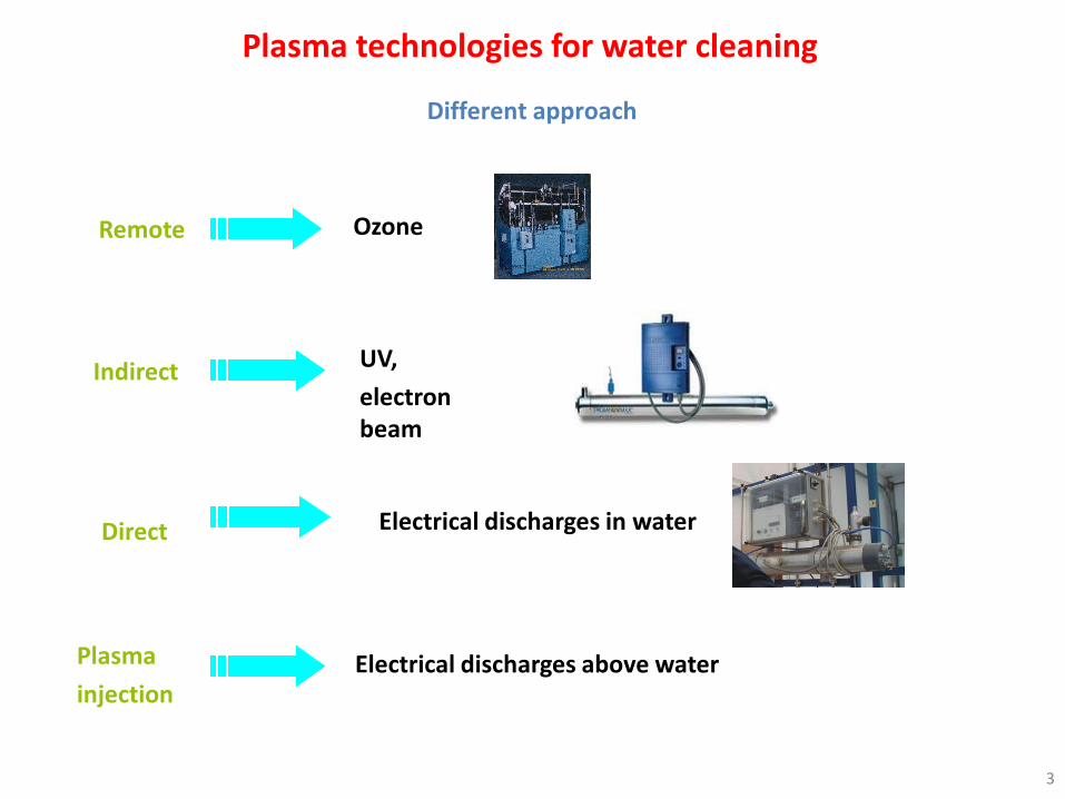
Electrical discharges used for water treatment
Direct liquid phase discharges – pulsed corona – conductivity
Prof. Mirosław Dors, [email protected] 32
Effect of the solution conductivity on temporal evolution of the integral light emission from the discharge (U = 21 kV).
Ph
oto
mu
ltip
lier
sugn
al[a
.u.]

Electrical discharges used for water treatment
Direct liquid phase discharges – pulsed corona – conductivity and spectra
Prof. Mirosław Dors, [email protected] 33
0 200 400 600 800
0,0
0,2
0,4
0,6
0,8
1,0
Puls
e e
nerg
y (J
)
Water conductivity (S/cm)
Hydrogen Balmer lines are responsible for thetypical magenta or blue–red colour.

Electrical discharges used for water treatment
Direct liquid phase discharges – pulsed corona – conductivity
Prof. Mirosław Dors, [email protected] 34
600 μS/cm 1.5 mS/cm
6 mS/cm 15 mS/cm
Role of ceramics: increasing the electrical field strength on the anode wire surface due to the redistribution of the field inside the interelectrode space during the prebreakdown stage, thus generating a larger number of discharge channels per pulse.
20 kV

Electrical discharges used for water treatment
Direct liquid phase discharges – pulsed corona – wire-to-plate
Prof. Mirosław Dors, [email protected] 35
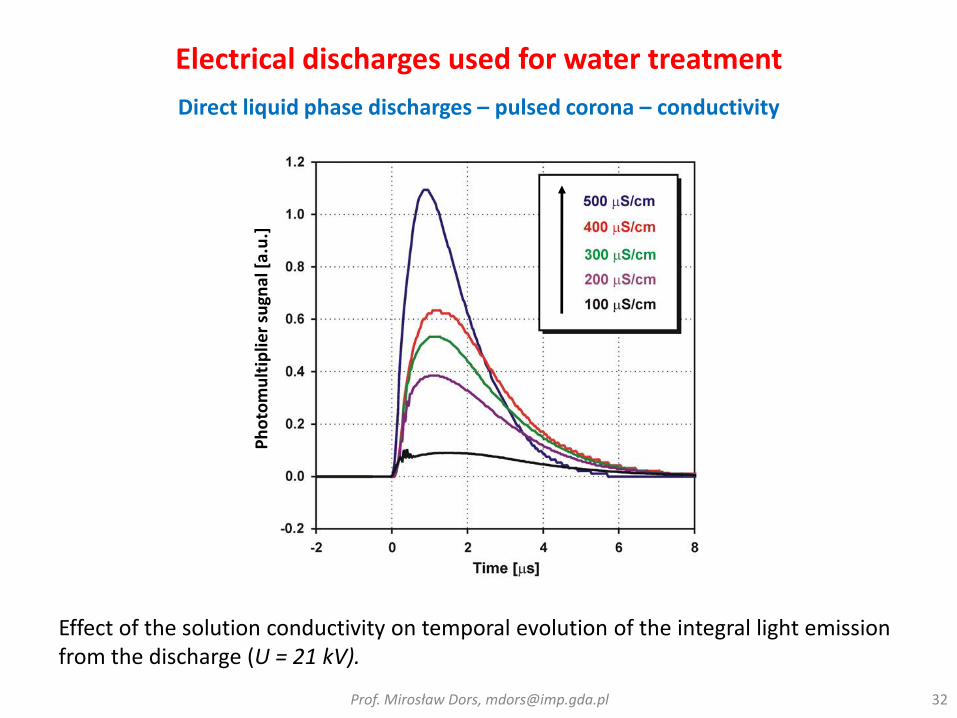
Electrical discharges used for water treatment
Direct liquid phase discharges with gas bubbles – pulsed corona
Prof. Mirosław Dors, [email protected] 36
Pulsed High
Voltage Wire
Electrical discharges used for water treatment
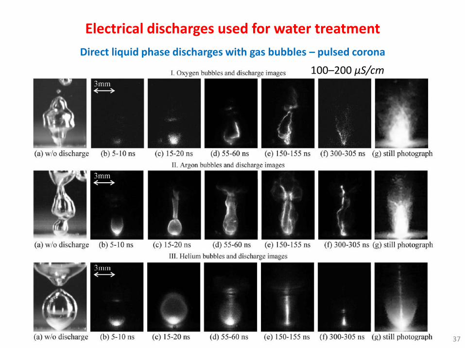
Direct liquid phase discharges with gas bubbles – pulsed corona
Prof. Mirosław Dors, [email protected] 37
100–200 μS/cm

Electrical discharges used for water treatment
Direct liquid phase discharges – pulsed arc
Prof. Mirosław Dors, [email protected] 38
Development of arc
In the pulsed corona the current is mostly transferred by electrons
High current heats a small volume of plasma (quasi-thermal plasma)

Electrical discharges used for water treatment
Direct liquid phase discharges – pulsed arc, pulsed spark, pulsed corona
Prof. Mirosław Dors, [email protected] 39
0 5 10 15 20-6000
-4500
-3000
-1500
0
1500
3000
時間 (s)
電圧
(V
)
(1mm) (5mm)(3mm)
Ton TonToff
0 5 10 15 20
時間 (s)
0 5 10 15 20
時間 (s)
-1.0
-0.5
0.0
0.5
1.0
1.5
2.0
電流
(A
)
Electrical discharges used for water treatment
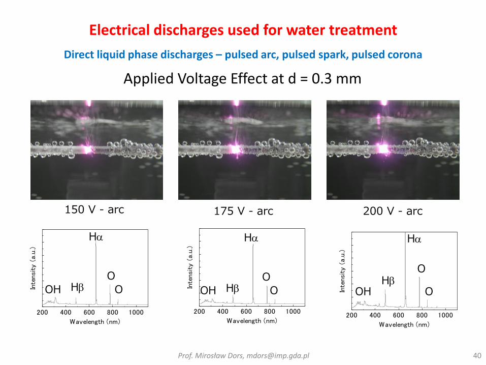
Direct liquid phase discharges – pulsed arc, pulsed spark, pulsed corona
Prof. Mirosław Dors, [email protected] 40
200 400 600 800 1000
Inte
nsi
ty (
a.u
.)
Wavelength (nm)200 400 600 800 1000
Inte
nsi
ty (
a.u
.)
Wavelength (nm)
150 V - arc 175 V - arc 200 V - arc
200 400 600 800 1000
Inte
nsi
ty (
a.u
.)
Wavelength (nm)
Ha
HbO
OOH
Ha
HbO
OOH
Ha
HbO
OOH
Applied Voltage Effect at d = 0.3 mm
Electrical discharges used for water treatment
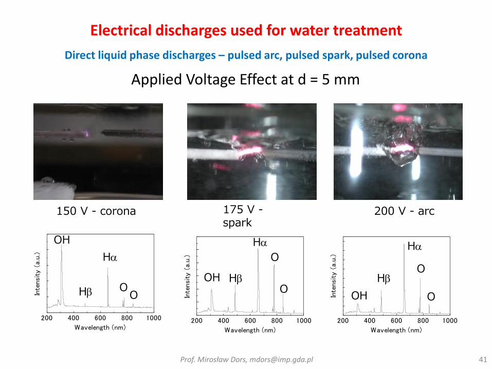
Direct liquid phase discharges – pulsed arc, pulsed spark, pulsed corona
Prof. Mirosław Dors, [email protected] 41
Applied Voltage Effect at d = 5 mm
200 400 600 800 1000
Inte
nsi
ty (
a.u
.)
Wavelength (nm)
200 400 600 800 1000
Inte
nsi
ty (
a.u
.)Wavelength (nm)
200 400 600 800 1000
Inte
nsi
ty (
a.u
.)
Wavelength (nm)
Ha
Hb OO
OH
150 V - corona 175 V -spark
200 V - arc
Ha
Hb
O
OOH
Ha
HbO
OOH

Electrical discharges used for water treatment
Direct liquid phase discharges – pulsed arc – UV radiation
Prof. Mirosław Dors, [email protected] 42
UV-A – 315-400 nm UV-B – 280-315 nm

Electrical discharges used for water treatment
Direct liquid phase discharges – pulsed arc – pressure wave
Prof. Mirosław Dors, [email protected] 43
Ps – shockwavePe – reflection wave
Measured 16 cm from the pulsed arc

Electrical discharges used for water treatment
Direct liquid phase discharges with gas bubbles – pulsed arc
Prof. Mirosław Dors, [email protected] 44
1 – Quartz cylinder
2 – Al top and bottom
3 – Copper electrodes
4 – Quartz gas tubes
5 – Arc discharge
6 – Liquid
7 – Drain hole
8, 9 – Sampling tubes
Electrical discharges used for water treatment
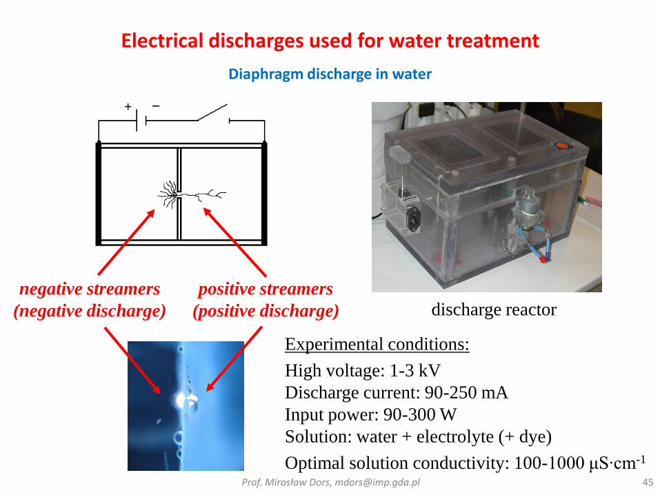
Diaphragm discharge in water
Prof. Mirosław Dors, [email protected] 45
negative streamers
(negative discharge)
positive streamers
(positive discharge) discharge reactor
Experimental conditions:
High voltage: 1-3 kV
Discharge current: 90-250 mA
Input power: 90-300 W
Solution: water + electrolyte (+ dye)
Optimal solution conductivity: 100-1000 μS∙cm-1

Electrical discharges used for water treatment
Hybrid reactors – combined discharges
Prof. Mirosław Dors, [email protected] 46
Separate charging by
two HV sources Charging by one HV source
Hybrid-series Hybrid-parallel

Electrical discharges used for water treatment
Hybrid-Series Gas-Liquid Electrical Discharge Reactor
Prof. Mirosław Dors, [email protected] 47
Simultaneous formation of discharge in water and in the gas above water surface (gap~5 mm)
HV: DC pulsed power supply (positive polarity U = 0-100 kV, C = 2 nF, f = 60 Hz)
Liquid phase point electrode: tungsten sharpened wire (curvature radius ~ 100 μm)
Gas phase planar electrode: Reticulated vitreous carbon (RVC) disk
Gas phase discharge
Liquid phase discharge
Electrical discharges used for water treatment
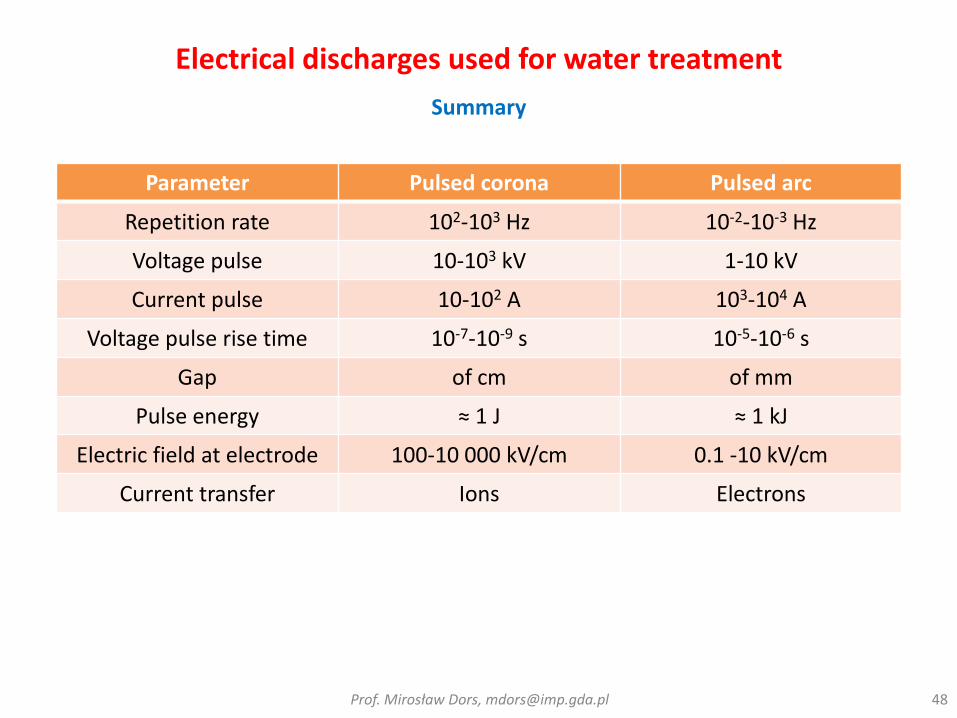
Summary
Prof. Mirosław Dors, [email protected] 48
Parameter Pulsed corona Pulsed arc
Repetition rate 102-103 Hz 10-2-10-3 Hz
Voltage pulse 10-103 kV 1-10 kV
Current pulse 10-102 A 103-104 A
Voltage pulse rise time 10-7-10-9 s 10-5-10-6 s
Gap of cm of mm
Pulse energy ≈ 1 J ≈ 1 kJ
Electric field at electrode 100-10 000 kV/cm 0.1 -10 kV/cm
Current transfer Ions Electrons

Electrical discharges used for water treatment
Summary
Prof. Mirosław Dors, [email protected] 49
Parameter Pulsed corona Pulsed arc
Plasma nature Non-thermal Quasi-thermal
Shockwave Week-moderate Strong
UVWeek-moderate
(conductivity dependence)Strong
Heat production Week Strong
Conductivity influence Strong Week
Electrode erosion Week Strong

Plasma technologies for water treatment - Remote
Ozone reactions
Low pH
High pH
50
F2
OHO
3.03
2.802.422.07 O3
[V]H2O21.78
Oxidation potential

Chemical processes induced in water
UV and Electron beam
Prof. Mirosław Dors, [email protected] 51
P. Gehringer, H. Eschweiler (2001)

Chemical processes induced in water
Removal of organic compounds – Electron beam
Prof. Mirosław Dors, [email protected] 52
Project of a commercial plant (Austria), 1993:
20 kW accelerator (500 keV) with ozone (1kg/h) treating 108 m3/h of groundwater forming 3 mm layer in the reactor
perchloroethylene (PCE): 61 µg/L => 1 µg/L using 200 J/L and ozone ≥ 6 mg/L
P. Gehringer, H. Eschweiler (2001)

Chemical processes induced in water
Processes induced by gas discharge to water surface
Prof. Mirosław Dors, [email protected] 53
Formation of OH radicals via electron impact dissociation of H2O in vapor
Vaporization of water surface=> formation of water vapor
Formation of ozone and its dissolution in water
Formation of OH radicals via reaction of excited O atoms with H2O in vapor
MOMOP)O( 323
ee H·OH·OH2OH·OH·OHD)O( 2
1
Formation of OH radicalsfrom ozone dissolved in
water

Chemical processes induced in water
Oxidative species from secondary reactions - diagnostics
Prof. Mirosław Dors, [email protected] 54
OH + OH → H2O2
OH + O3 → HO2 + O2
H + O3 → OH + O2
HO2 + O3 → OH + 2O2
HO2 + H → H2O2
Indirect measurements of short lived species (e.g. OH
radicals) through chemical changes of model organic
compounds in water
phenol and substituted phenols
Direct measurements of produced long-lived chemical active species
simultaneous production of ozone decrease in the gas and H2O2 production in water

Chemical processes induced in water
Diagnostics
Prof. Mirosław Dors, [email protected] 55
HPLC (High Performance Liquid Chromatography) - for organic compounds measurements,
UV-VIS spectrometry - analysis in UV range and visible range of light for diagnostics of inorganic compounds, like O3, H2O2 and OH radicals:
O3 – iodometric method: O3 + 2KJ + H2O J2 + 2KOH + O2 (give pink complex with N,N-dimethyl-p-phenylenediamine), λ=515 nm; or reaction with Indigodye, λ=600 nm
H2O2 – reaction with titanyl ions: Ti4+ + H2O2 + 2 H2O TiO2.H2O2 + 4 H+ (give yellow complex), λ=407 nm
TOC analysis - which Total Organic Carbon analysis - for the measurement of the sum of organic compounds:
mineralization and measurement of produced CO2 (e.g. IR measurement)
Microbiological analysis – different for specific microorganisms.

Chemical processes induced in water
Diagnostics – OH radicals
Prof. Mirosław Dors, [email protected] 56
in plasma -> Optical Emission Spectroscopy (OES), λ=309 nm
in water -> fluorescence:
with terephthalate, λ=426 nm (excitation at λ=312 nm)
with coumarin 3-carboxylic acid (CCA), λ=450 nm (excitation at λ=396 nm)
with benzoate, λ=350 nm (excitation at λ=300 nm)
with phenoxazinone, λ=585 nm (excitation at λ=570 nm)
with indoxyl-β-glucuronide (IBG)

Chemical processes induced in water
Gas phase discharge - oxidation reactions
Prof. Mirosław Dors, [email protected] 57
0 20 40 60 80 100
0,00
0,05
0,10
0,15
0,20
0,25
0,30
O3 a
qu
eo
us (
mM
)
Processing time (min)
H2O
H2O + Phenol
0 20 40 60 80 100
0
50
100
150
200
250
O3 g
ase
ou
s (
pp
m)
Processing time (min)
H2O
H2O + Phenol
O3 => OH => Phenol

Chemical processes induced in water
Oxidation reactions in water
Prof. Mirosław Dors, [email protected] 58
0 20 40 60 80 100
0,00
0,05
0,10
0,15
0,20
0,25
0,30
H2O
2
(mM
)
Processing time (min)
H2O
H2O + Phenol
0 20 40 60 80 100
0,000
0,005
0,010
0,015
0,020
0,025
0,030
Co
nce
ntr
atio
n
(mM
)
Processing time (min)
Phenol
Dihydroxyphenols
Consumption of OH leads to decreased production of H2O2
Phenol => Dihydroxyphenols(Catechol, Hydroquinone, Resorcinol)
Organic acids

Chemical processes induced in water
Oxidation reactions – OH attack on Phenol ring
Prof. Mirosław Dors, [email protected] 59
- HO2.
OH
OH O
O
OH OH
OH
OH
OHOO.
OH
OHOO.
OH
OH
O
O
OH.
HCHD .
- 2 H+
+ 2 H+
- 2 H+
+ 2 H+
O2 O2 Ring opened
products. O
O
- HO2.

Chemical processes induced in water
Oxidation reactions – O3 attack on Phenol ring
Prof. Mirosław Dors, [email protected] 60
OH
O
O
OOH
H
O3
O3
OO
OOH
H
+
OH
OH
- H2O
2- H2O
- O2
O3
O
O
OOH
OH
O3
OH
OH
C
C
O
O
OH
OH
C
C
O
O
OH
H
C
CH
O
OH
OH
OOH
muconaldehydecis,cis-muconic acid
H2O

Chemical processes induced in water
Hybrid gas-liquid discharge – influence of gas
Prof. Mirosław Dors, [email protected] 61
0
100
200
300
400
500
0 10 20 30 40 50 60 70
Ph
en
ol co
ncen
trati
on
[
M]
Degradation time [min]
liquid-only
hybrid-O2
hybrid-Ar
Initial conditions: pH=3.6, σ=100 μS/cm

Chemical processes induced in water
Hybrid gas-liquid discharge – influence of gas
Prof. Mirosław Dors, [email protected] 62
Argon atmosphere
Oxygen atmosphere
OH
OH
OH
OH
O
O
COOH
COOH
hydroquinonecatechol 1,4-benzoquinone maleic acid
OH
OH
OH
OH
O
O
COOH
COOH
COOH
COOH
COOH
COOH
cis,cis-muconic acidhydroquinonecatechol 1,4-benzoquinone maleic acidcis,trans-muconic acid

Chemical processes induced in water
Hybrid gas-liquid discharge – influence of pH
Prof. Mirosław Dors, [email protected] 63
Hybrid-O2 atmosphere Hybrid-Ar atmosphere
-2.5
-2
-1.5
-1
-0.5
0
0 1000 2000 3000 4000
Treatment time [s]ln
(c/c
0)
H2SO4
(pH=3.6)
Na2SO4
(pH=5.1)
NaOH
(pH=10.2)
pH=5.1
pH=10.2
pH=3.6
-2.5
-2
-1.5
-1
-0.5
0
0 1000 2000 3000 4000
Treatment time [s]
ln(c
/c0)
pH=5.1
pH=10.2
pH=3.6

Chemical processes induced in water
Hybrid gas-liquid discharge – influence of pH
Prof. Mirosław Dors, [email protected] 64
OH O
0
0.2
0.4
0.6
0.8
1
7 8 9 10 11 12 13
pH
a
OH O
OH-
H+
pK = 9.89
OH
O
3O kO3 = 1.4 x 10⁹ M-1 s-1
3O kO3 = 1.3 x 10³ M-1 s-1
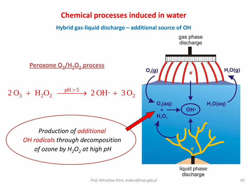
Chemical processes induced in water
Hybrid gas-liquid discharge – additional source of OH
Prof. Mirosław Dors, [email protected] 65
25pH
223 O3OH·2OHO2
Production of additional
OH radicals through decomposition
of ozone by H2O2 at high pH
Peroxone O3/H2O2 process
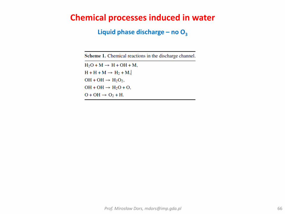
Chemical processes induced in water
Liquid phase discharge – no O3
Prof. Mirosław Dors, [email protected] 66

Chemical processes induced in water
Liquid phase discharge – no O3
Prof. Mirosław Dors, [email protected] 67
0 20 40 60
0,0
0,5
1,0
1,5
H2O
2 (m
M)
Processing time (min)
1 S/cm
303 S/cm
606 S/cm
Tap water (580 S/cm)
- OH as the only oxidative species- dependence on the conductivity
)sthermolysiphotolysis(iondecompositreaction)order -zero(productiondt
]OH[d 22
ph
oto
lysi
sra
te/a
ll d
eco
mp
osi
ton
rate
1 S/cm 200 S/cm

Chemical processes induced in water
Liquid phase discharge – Phenol oxidation
Prof. Mirosław Dors, [email protected] 68
0 20 40 60 80 100
0,0
0,1
0,2
0,3
0,4
0,5
0,6
0,7
Phenols
concentr
ation (
mM
)
Processing time (min)
Phenol, without Fe2+
Phenol, with Fe2+
Dihydroxyphenols, with Fe2+
0 20 40 60 80 100
0,0
0,1
0,2
0,3
0,4
0,5
0,6
0,7
Phenols
concentr
ation (
mM
)
Processing time (min)
Phenol, without Fe2+
Phenol, with Fe2+
Dihydroxyphenols, with Fe2+
0 20 40 60 80 100
0,0
0,1
0,2
0,3
0,4
0,5
0,6
0,7
Phenols
concentr
ation (
mM
)
Processing time (min)
Phenol, without Fe2+
Phenol, with Fe2+
Dihydroxyphenols, with Fe2+
200 S/cm 600 S/cm1 S/cm
Fe2+ + H2O2 Fe3+ + OH- + OH
Enhancement by Fenton reaction:

Chemical processes induced in water
Removal of organic compounds – Pulsed Arc Electrohydraulic Discharge
Prof. Mirosław Dors, [email protected] 69
Reduction of TOC in Sludge-Water (d = 0.5mm, V = 1-2.2kV)
0
50
100
150
200
250
300
350
0 20 40 60 80 100 120
TOC
co
nce
ntr
atio
n (
mg
/L)
PAED treatment time (min)
Sludge-water
Pond surface water
Pond bottom water with 33g/L sediment
Pondbottom water with 100g/L sediment

Chemical processes induced in water
Removal of organic compounds – Pulsed Arc Electrohydraulic Discharge
Prof. Mirosław Dors, [email protected] 70
Generations of gaseous by-products (CO, CO2, CxHy, SO2 and H2S (sludge-water, Initial TOC =120mg/L)
0
1
2
3
4
5
6
7
8
9
0 50 100 150
Acc
um
ula
ted
CO
, CO
2an
d C
xHy
(mg/
L)
Treatment time (min)
[CO]
[CO2]
[CxHy]
0,00
0,05
0,10
0,15
0,20
0,25
0,30
0,35
0 50 100 150
Acc
um
ula
ted
SO2
and
H2S
(mg/
L)
Treatment time (min)
[SO2]
[H2S]
d = 0.5mm, V = 1kV

Chemical processes induced in water
Removal of organic compounds – Pulsed Arc Electrohydraulic Discharge
Prof. Mirosław Dors, [email protected] 71
Change in Water Quality (Dissolved Oxygen)
0
1
2
3
4
5
6
7
0 20 40 60 80 100 120Dis
solv
ed
oxy
gen
co
nce
ntr
atio
n (
mg
/L)
PAED treatment time (min)
Pond water
Pond water with 33g/L sediment
Chemical processes induced in water
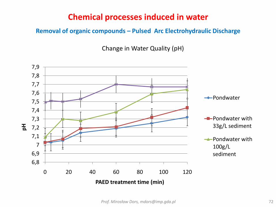
Removal of organic compounds – Pulsed Arc Electrohydraulic Discharge
Prof. Mirosław Dors, [email protected] 72
Change in Water Quality (pH)
6,8
6,9
7
7,1
7,2
7,3
7,4
7,5
7,6
7,7
7,8
7,9
0 20 40 60 80 100 120
pH
PAED treatment time (min)
Pondwater
Pondwater with 33g/L sediment
Pondwater with 100g/L sediment

Chemical processes induced in water
Removal of organic compounds – Pulsed Arc Electrohydraulic Discharge
Prof. Mirosław Dors, [email protected] 73
Change in Water Quality (Conductivity)
200
250
300
350
400
450
500
550
600
650
700
0 20 40 60 80 100 120
Co
nd
uct
ivit
y (m
S/m
)
PAED treatment time (min)
Pond water
Pond water with 33g/L sediment"
Pond water with 100g/L sediment"Sludge-water

Organic compounds decomposition
Prof. Mirosław Dors, [email protected] 74
phenols trichloroethylene polychlorinated biphenyl perchloroethylene pentachlorophenol acetophenone organic dyes (such as methylene blue) aniline anthraquinone monochlorophenols methyl tert-butyl ether (MTBE) benzene toluene ethyl benzene (BTEX) 2,4,6-trinitrotoluene 4-chlorophenol 3,4-dichloroaniline

Biocidal effects
Disinfection mechanisms – UV irradiation
Prof. Mirosław Dors, [email protected] 75
• 240 to 280 nm - damaging nucleic acids of microorganisms
(Tchobanoglous, 1997)
HOWEVER,
Under certain conditions, some organisms are capable of repairingdamaged DNA and reverting back to an active state in which reproduction is again possible – “Dark repair mechanisms”

UV irradiation – requirements for disinfection
Surface Water Treatment Rules – Minimum Treatment Requirements1
Regulation Giardia Virus Cryptosporidium
US EPA Long Term 2 Enhanced Surface Water Treatment Rule
3-log removal (99.9%)
4-log removal (99.99%)
2.5-log additional treatmentfor filtered systems
3-log additional treatmentfor unfiltered systems
UV Dose Requirements (mJ/cm2)
Target pathogensLog inactivation
0.5 1.0 1.5 2.0 2.5 3.0 3.5 4.0
Cryptosporidium 1.6 2.5 3.9 5.8 8.5 12 15 22
Giardia 1.5 2.1 3.0 5.2 7.7 11 15 22
Virus 39 58 79 100 121 143 163 186most viruses can be easily inactivated with chlorine so UV disinfection for virus inactivation may not be necessary
76
Biocidal effects

Biocidal effect of electrohydraulic discharges
Prof. Mirosław Dors, [email protected] 77
Spark/Arc Corona Ozonation Fenton Peroxone
• OH, HO2,
H2O2
• UV
irradiation
• shock wave
• heat
• OH, HO2,
H2O2, O3
• UV
irradiation
• O3
• OH
• OH • OH
• O3
2 O3 + H2O2 → 2 OH + 3 O2
O3 + OH- → O3- + OH
Fe2+ + H2O2 → Fe3+ + OH + OH−

Biocidal effect of electrohydraulic discharges
River water disinfection - number of microorganisms
Prof. Mirosław Dors, [email protected] 78
Microorganismsgrown in 360C
Microorganisms grown in 220C
0 100 200 300 400 500 600 700
0,01
0,1
1
10
Tota
l num
ber
of m
icro
org
anis
ms in 3
60C
(10
3 c
fu/m
l)
Processing time (s)
Ozonation
Spark
Corona
Before
0 100 200 300 400 500 600 700
0,01
0,1
1
10
Tota
l num
ber
of m
icro
org
anis
ms in 2
20C
(10
4 c
fu/m
l)
Processing time (s)
Ozonation
Spark
CoronaBefore

Biocidal effect of electrohydraulic discharges
River water disinfection - number of microorganisms
Prof. Mirosław Dors, [email protected] 79
E. coli Total coli
0 100 200 300 400 500 600 700
0,01
0,1
1
10
100
Tota
l num
ber
of E
. C
oli
bacte
ria (
cfu
/ml)
Processing time (s)
Ozonation
Spark
Corona
Before
0 100 200 300 400 500 600 700
0,01
0,1
1
10
Tota
l num
ber
of C
oli
bacte
ria (
10
3 c
fu/m
l)
Processing time (s)
Ozonation
Spark
Corona
Before
Biocidal effect of electrohydraulic discharges
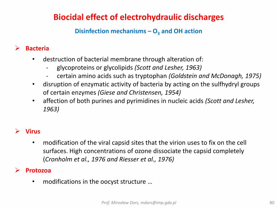
Disinfection mechanisms – O3 and OH action
Prof. Mirosław Dors, [email protected] 80
• destruction of bacterial membrane through alteration of:- glycoproteins or glycolipids (Scott and Lesher, 1963)- certain amino acids such as tryptophan (Goldstein and McDonagh, 1975)
• disruption of enzymatic activity of bacteria by acting on the sulfhydryl groups of certain enzymes (Giese and Christensen, 1954)
• affection of both purines and pyrimidines in nucleic acids (Scott and Lesher, 1963)
Bacteria
Virus
• modification of the viral capsid sites that the virion uses to fix on the cell surfaces. High concentrations of ozone dissociate the capsid completely (Cronholm et al., 1976 and Riesser et al., 1976)
Protozoa
• modifications in the oocyst structure …
Biocidal effect of electrohydraulic discharges
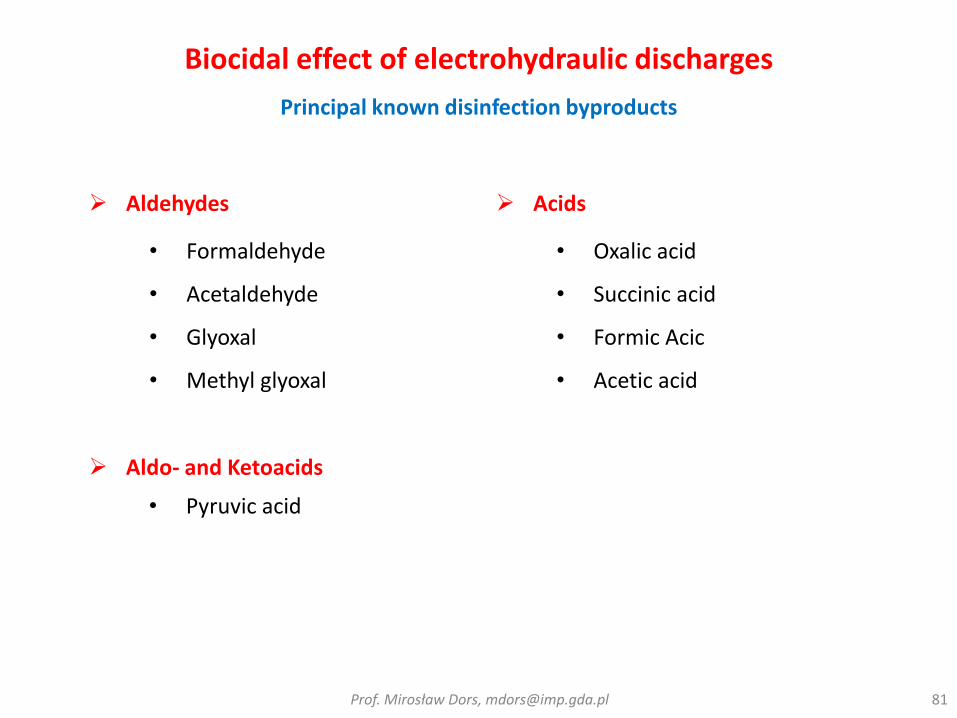
Principal known disinfection byproducts
Prof. Mirosław Dors, [email protected] 81
• Formaldehyde
• Acetaldehyde
• Glyoxal
• Methyl glyoxal
Aldehydes Acids
• Oxalic acid
• Succinic acid
• Formic Acic
• Acetic acid
Aldo- and Ketoacids
• Pyruvic acid

Biocidal effect of electrohydraulic discharges
Pulsed Arc Electrohydraulic Discharge
Prof. Mirosław Dors, [email protected] 82
0,0
0,2
0,4
0,6
0,8
1,0
1,2
1,4
1,6
1,8
2,0
0 100 200 300 400 500 600
Lo
g R
em
ova
l
Number of Pulses
8.05 mS/m
4.3 mS/m (1)
4.3 mS/m (2)
532 uS/m (1)
532 uS/m (2)
532 uS/m (3)
E. coli inactivation
•V = 4kV•PAED: 5 sec/pulse, 100 pulse = 9min•Accumulative energy for 100pulses for high conductivity water = 2.8 kWh/m3•Accumulative energy for 100, 300, 400, 500 pulses for low conductivity water = 6.3, 19, 25.3 and 31.6 kWh/m3

0,0
0,2
0,4
0,6
0,8
1,0
1,2
1,4
1,6
1,8
2,0
0 100 200 300 400 500 600
Lo
g R
em
ova
l
Number of Pulses
588 uS (1)
588 uS (2)
588 uS (3)
588 uS (4)- LP
Biocidal effect of electrohydraulic discharges
Pulsed Arc Electrohydraulic Discharge
Prof. Mirosław Dors, [email protected] 83
Bacillus subtilis inactivation
•V = 4kV•PAED: 5 sec/pulse, 100 pulse = 9min•Accumulative energy for 100pulses for high conductivity water = 2.8 kWh/m3•Accumulative energy for 100, 300, 400, 500 pulses for low conductivity water = 6.3, 19, 25.3 and 31.6 kWh/m3

Biocidal effect of electrohydraulic discharges
Pulsed arc in the sea water – removal of algae and mussels
Prof. Mirosław Dors, [email protected] 84
Before After

Biocidal effect of electrohydraulic discharges
Pulsed Arc Electrohydraulic Discharge
Prof. Mirosław Dors, [email protected] 85
0
20
40
60
80
100
120
0 20 40 60 80 100 120 140 160 180
Time (hrs)
Mo
rta
lity
(%
)
Lake Ballast Water 1 with10 minutes treatment
Lake Ballast Water 1 with 2pulsed treatment
Lake Ballast water 1 forcontrol
Lake Ballast Water 2 with10 minutes treatment
Mortality of Zooplankton (Lake Ballast Water, 30 animals/L, V =2.3kV, d =0.5mm)
Time after PAED treatment (hrs)
1mm

Biocidal effect of electrohydraulic discharges
Pulsed arc in the sea water – disinfection, pilot station
Prof. Mirosław Dors, [email protected] 86
d
l
#
2
dl
1m 1mWater Out
Water In
50L/min
235mm
185mm
185mm
Ti Electrodes
I.D =
82.5mm
Regional Municipality of Waterloo’s Mannheim Drinking Water Treatment Plant, Canada – Pulsed arc discharge in water ● 50 L/s● E. coli● B. subtilis● Natural Organic Matter● MTBE

Comparison to other water treatment technologies
Prof. Mirosław Dors, [email protected] 88
Chemical Optical RadiolysisGas
Discharges
Electrohydraulic
Discharges
Ozone Cl/ClO2 UV-C
UV-
Photo-
catatyst
E-
beam-Ray Corona Barrier
Pulsed
Spark
Pulsed
Arc
Micro-organisms O O O O
Oxidation Power X
Algae Destruction X O X X X X X
Urine Components
Destruction O X O
VOCs Destruction O X X O O O
Removal of Inorganics X X O O
- Good O - Adequate - Partial x - None

Summary
Energy efficiency of plasma in water cleaning
Prof. Mirosław Dors, [email protected] 89
AC-GlidArc AC gliding arc discharges, Ar argon, Co initial concentration of dye in treat-water, CGDE contact glow discharge electrolysis, DD diaphragm discharges, GDE glow discharge electrolysis, G50 energy yield at 50% conversion, HS-PCD hybrid-series pulsed corona discharges, MWD microwave discharges, DBD dielectric barrier discharges, DC direct current, O2 oxygen, O3 ozone, PCD pulsed corona discharges, RFD radio-frequency discharges, RT refers to the number of row from which values of ‘REEr’ and ‘G50r’ are taken to calculate ‘REE’, REE relative energy efficiency, SD spark discharges, SSD streamer and spark discharges, UV ultraviolet radiations

Other applications
As a source of seismic waves – sea bed mapping
Prof. Mirosław Dors, [email protected] 90

References• Locke B R, Sato M, Sunka P, Hoffmann M R and Chang J S, 2006 , Electrohydraulic discharge and nonthermal plasma, for
water treatment Indust. Eng. Chem. Res. 45 882–905
• Malik M A, Ghaffar A and Malik S A 2001 Water, purification by electrical discharges Plasma Sources Sci., Technol. 10 82–91
• An W, Baumung K and Bluhm H 2007 Underwater streamer propagation analyzed from detailed measurements of pressure release J. Appl. Phys. 101 053302
• Sato K and Yasuoka K 2008 Pulsed discharge development in oxygen, argon, and helium bubbles in water IEEE Trans. Plasma Sci. 36 1144–5
• Sunka P, Babicky V, Clupek M, Lukes P, Simek M, Schmidt J and Cernak M 1999 Generation of chemically active species by electrical discharges in water Plasma Sources Sci. Technol. 8 258–65
• J. S. Chang, “Thermal Plasma Solid Waste and Water Treatments: A Critical Review,” Int. J. Plasma Env. Sci. Techn., vol. 3, no. 2, 2009
• Lukes P and Locke B R 2005 Plasmachemical oxidation processes in a hybrid gas–liquid electrical discharge reactor J. Phys. D: Appl. Phys. 38 4074–81
• P H Ceccato, O Guaitella, M Rabec Le Gloahec and A Rousseau, Time-resolved nanosecond imaging of the propagation of a corona-like plasma discharge in water at positive applied voltage polarity, J. Phys. D: Appl. Phys., 43 (2010) 175202
• A.A. Joshi, B.R. Locke, P. Arce, W.C. Finney, ”Formation of hydroxyl radicals, hydrogen peroxide and aqueous electrons by pulsed streamer corona discharge in aqueous solution”, Journal of Hazardous Materials, vol. 41, pp. 3-30, 1995
• N. Karpel Vel Leitner, G. Syoen, H. Romat, K. Urashima, J.-S. Chang, Generation of active entities by the pulsed arc electrohydraulic discharge system and application to removal of atrazine, Water Research 39 (2005) 4705–4714
• Sugiarto, A. T.; Sato, M. Pulsed plasma processing of organic compounds in aqueous solution. Thin Solid Films 2001, 386, 295
• A. Abou-Ghazala, S. Katsuki, Karl H. Schoenbach, F. C. Dobbs, and K. R. Moreira, Bacterial Decontamination of Water byMeans of Pulsed-Corona Discharges, IEEE Trans. Plasma Sci. , 30 (2002) 4, 1449-1453
• M. Dors, J. Mizeraczyk, Y.S. Mok, Phenol Oxidation in Aqueous Solution by Gas Phase Corona Discharge, Journal of AdvancedOxidation Technologies, 9, 139-143, 2006
• M. Dors, E. Metel, J. Mizeraczyk, Phenol Degradation in Water by Pulsed Streamer Corona Discharge and Fenton Reaction, Int. J. Plasma Environ. Sci. Technol., 1, 76-81, 2007
• M. Dors, E. Metel, J. Mizeraczyk, E. Marotta, Coli bacteria inactivation by pulsed corona discharge in water, Int. J. Plasma Environ. Sci. Technol., 2, 34-37, 2008
• Fridman A., Plasma Chemistry, Cambridge University Press, 2008Prof. Mirosław Dors, [email protected] 91