PLASMA CUTTING MACHINE TORCH - Welding … equipment/automated systems … · PLASMA CUTTING...
174
81 Rev. AD.01 Date: April 2, 2007 Manual # 0-4641 Operating Features: Operating Manual AUTOMATED PLASMA CUTTING SYSTEM CUTMASTER ™ Art # A-04611 SL100SV PLASMA CUTTING MACHINE TORCH
Transcript of PLASMA CUTTING MACHINE TORCH - Welding … equipment/automated systems … · PLASMA CUTTING...

81
Rev. AD.01 Date: April 2, 2007 Manual # 0-4641Operating Features:
Operating Manual
AUTOMATEDPLASMA CUTTING SYSTEM
CUTMASTER™
Art # A-04611
SL100SVPLASMA CUTTINGMACHINE TORCH

WE APPRECIATE YOUR BUSINESS!Congratulations on your new Thermal Dynamics product. We areproud to have you as our customer and will strive to provide youwith the best service and reliability in the industry. This product isbacked by our extensive warranty and world-wide service network.To locate your nearest distributor or service agency call 1-800-426-1888, or visit us on the web at www.thermal-dynamics.com.
This Operating Manual has been designed to instruct you on thecorrect use and operation of your Thermal Dynamics product.Your satisfaction with this product and its safe operation is ourultimate concern. Therefore please take the time to read the entiremanual, especially the Safety Precautions. They will help you toavoid potential hazards that may exist when working with thisproduct.
YOU ARE IN GOOD COMPANY!The Brand of Choice for Contractors and Fabricators Worldwide.
Thermal Dynamics is a Global Brand of manual and automationPlasma Cutting Products for Thermadyne Industries Inc.
We distinguish ourselves from our competition through market-leading, dependable products that have stood the test of time.We pride ourselves on technical innovation, competitive prices,excellent delivery, superior customer service and technicalsupport, together with excellence in sales and marketing expertise.
Above all, we are committed to developing technologicallyadvanced products to achieve a safer working environment withinthe welding industry.

WARNINGS
Read and understand this entire Manual and your employer’s safety practices before installing, operat-ing, or servicing the equipment.
While the information contained in this Manual represents the Manufacturer's best judgement, theManufacturer assumes no liability for its use.
Automated Plasma Cutting SystemAutomated CutMaster™ 81 Power SupplySL100 Machine TorchOperating Manual Number 0-4641
Covered under U.S. Patents.
Published by:Thermal Dynamics Corporation82 Benning StreetWest Lebanon, New Hampshire, USA 03784(603) 298-5711
www.thermal-dynamics.com
© Copyright 2004, 2005, 2006, 2007 byThermal Dynamics Corporation
All rights reserved.
Reproduction of this work, in whole or in part, without written permission of the pub-lisher is prohibited.
The publisher does not assume and hereby disclaims any liability to any party for anyloss or damage caused by any error or omission in this Manual, whether such errorresults from negligence, accident, or any other cause.
Printed in the United States of America
Publication Date: April 2, 2007
Record the following information for Warranty purposes:
Where Purchased:____________________________________
Purchase Date:_______________________________________
Power Supply Serial #:________________________________
Torch Serial #:________________________________________


TABLE OF CONTENTS
SECTION 1:GENERAL INFORMATION ................................................................................................ 1-1
1.01 Notes, Cautions and Warnings ...................................................................... 1-11.02 Important Safety Precautions ....................................................................... 1-11.03 Publications .................................................................................................. 1-31.04 Note, Attention et Avertissement .................................................................. 1-31.05 Precautions De Securite Importantes ........................................................... 1-41.06 Documents De Reference ............................................................................. 1-51.07 Declaration of Conformity ............................................................................. 1-71.08 Statement of Warranty .................................................................................. 1-8
SECTION 2: SPECIFICATIONS ................................................................................................ 2-1
2.01 Scope of Manual .......................................................................................... 2-12.02 Power Supply Specifications......................................................................... 2-12.03 Input Wiring Specifications ........................................................................... 2-22.04 Power Supply Features ................................................................................. 2-32.05 Power Supply Options and Accessories ....................................................... 2-42.06 Torch Specifications ..................................................................................... 2-52.07 Torch Options and Accessories .................................................................... 2-62.08 Introduction to Plasma.................................................................................. 2-7
SECTION 3: INSTALLATION ..................................................................................................... 3-1
3.01 Unpacking .................................................................................................... 3-13.02 Lifting Options .............................................................................................. 3-13.03 Primary Input Power Connections ................................................................. 3-23.04 Gas Connections .......................................................................................... 3-43.05 Torch Connections ........................................................................................ 3-73.06 Torch Installation .......................................................................................... 3-93.07 Torch Parts Selection...................................................................................3-103.08 Power Supply Connection to SC-11 Standoff Control ...................................3-113.09 Power Supply Connection to Alternate Standoff Control ............................... 3-123.10 Automation Interface PC Board Set-up ........................................................3-143.11 Optional Remote Current Control Harness Installation.................................. 3-15
SECTION 4: OPERATION ......................................................................................................... 4-1
4.01 Product Features .......................................................................................... 4-14.02 Preparations For Operating ........................................................................... 4-24.03 Selection, Inspection and Replacement of Consumable Torch Parts ............. 4-64.04 Cut Quality ................................................................................................... 4-84.05 General Cutting Information .......................................................................... 4-94.06 Torch Operation ........................................................................................... 4-104.07 Cutting Parameters ......................................................................................4-124.08 Cutting Specifications .................................................................................. 4-134.09 Cutting Speed Chart: Mild Steel, SL100 Torch with Exposed Tip .................. 4-144.10 Cutting Speed Charts: Stainless Steel, SL100 Torch with Exposed Tip ........4-154.11 Cutting Speed Charts: Aluminum, SL100 Torch with Exposed Tip ................ 4-164.12 Cutting Speed Charts: Mild Steel, SL100 Torch with Shielded Tip ................ 4-174.13 Cutting Speed Charts: Stainless Steel, SL100 Torch with Shielded Tip ........4-184.14 Cutting Speed Charts: Aluminum, SL100 Torch with Shielded Tip ................ 4-194.15 Operator's Custom Cutting Speed Charts .................................................... 4-20

TABLE OF CONTENTS (continued)SECTION 5:
SERVICE .......................................................................................................................... 5-1
5.01 General Maintenance .................................................................................... 5-15.02 Common Faults ............................................................................................ 5-55.03 Basic Troubleshooting ................................................................................... 5-65.04 Advanced Troubleshooting Guide - General Information ............................... 5-115.05 Main Input and Internal Power Problems ...................................................... 5-135.06 Pilot Arc Problems....................................................................................... 5-195.07 Main Arc Problems ......................................................................................5-245.08 Test Procedures ........................................................................................... 5-255.09 Power Supply Major External Parts Replacement ........................................ 5-315.10 Front Panel Parts Replacement ....................................................................5-335.11 Left Side Internal Parts Replacement .......................................................... 5-355.12 Right Side Internal Parts Replacement ........................................................5-42
SECTION 6:PARTS LISTS ................................................................................................................... 6-1
6.01 Introduction ................................................................................................... 6-16.02 Ordering Information ..................................................................................... 6-16.03 Complete Power Supply Replacement .......................................................... 6-16.04 Power Supply Basic Replacement Parts ....................................................... 6-26.05 Power Supply Options and Accessories ....................................................... 6-26.06 Power Supply Major External Replacement Parts ......................................... 6-36.07 Power Supply Front Panel Replacement Parts ............................................. 6-46.08 Rear Panel Replacement Parts .................................................................... 6-56.09 Power Supply Left Side Internal Replacement Parts .................................... 6-66.10 Right Side Internal Replacement Parts ........................................................ 6-86.11 Torch Replacement Parts .............................................................................6-106.12 Torch Replacement Parts .............................................................................6-126.13 Torch Consumables ..................................................................................... 6-146.14 Torch Spare Parts Kits ................................................................................. 6-146.15 Complete Torch Assembly Replacement ...................................................... 6-166.16 Torch Options & Accessories ...................................................................... 6-16
PATENT INFORMATION ...........................................................................................................6-17
APPENDIX 1: SEQUENCE OF OPERATION(BLOCK DIAGRAM) .......................................................................................................... A-1
APPENDIX 2: DATA TAG INFORMATION ................................................................................ A-2
APPENDIX 3: MAINTENANCE SCHEDULE ............................................................................. A-3
APPENDIX 4: TORCH PIN - OUT DIAGRAMS .......................................................................... A-4
APPENDIX 5: TORCH CONNECTION DIAGRAMS .................................................................. A-5
APPENDIX 6: CONTROL CABLE PIN - OUT DIAGRAM .......................................................... A-6
APPENDIX 7: INTERFACE PCB SWITCH SETTINGS (MOST COMMON SETTINGS) ............ A-7

TABLE OF CONTENTS
APPENDIX 8: INTERFACE PCB SWITCH SETTINGS (Division Factors 16-24) ....................... A-8
APPENDIX 9: INTERFACE PCB SWITCH SETTINGS (Division Factors 24-30) ....................... A-9
APPENDIX 10: INTERFACE PCB SWITCH SETTINGS (Division Factors 30-33) ................... A-10
APPENDIX 11: INTERFACE PCB SWITCH SETTINGS (Division Factors 33-36) ................... A-11
APPENDIX 12: INTERFACE PCB SWITCH SETTINGS (Division Factors 36-43) ................... A-12
APPENDIX 13: INTERFACE PCB SWITCH SETTINGS (Division Factors 43-50) ................... A-13
APPENDIX 14: AUTOMATION INTERFACE PC BOARD WIRING LAYOUT ............................ A-14
APPENDIX 15: AUTOMATION INTERFACE PC BOARD LAYOUT and TEST POINTS ........... A-15
APPENDIX 16: AUTOMATION INTERFACE PC BOARD WIRING CONNECTIONS TOOEM CNC HARNESS .................................................................................................... A-16
APPENDIX 17: AUTOMATION INTERFACE PC BOARD WIRING CONNECTIONS TOALTERNATE CNC HARNESS.......................................................................................... A-17
APPENDIX 18: MAIN PC BOARD LAYOUT ............................................................................ A-18
APPENDIX 19: MAIN PC BOARD WIRING LAYOUT (208 /230-Volt POWER SUPPLIES) ...... A-20
APPENDIX 20: MAIN PC BOARD WIRING LAYOUT (400-Volt, 415-Volt, 460-Volt,600-Volt POWER SUPPLIES) ......................................................................................... A-21
APPENDIX 21: LOGIC BOARD LAYOUT ................................................................................ A-22
APPENDIX 22: POT / LED BOARD LAYOUT .......................................................................... A-23
APPENDIX 23: OUTPUT BOARD WIRING DIAGRAM ............................................................ A-24
APPENDIX 24: OUTPUT DIODE BOARD LAYOUT ................................................................ A-25
APPENDIX 25: PILOT BOARD LAYOUT ................................................................................. A-26
APPENDIX 26: 28VAC CIRCUIT DIAGRAM ........................................................................... A-27
APPENDIX 27: INPUT DIODE LAYOUT.................................................................................. A-28
APPENDIX 28: 208/230V SYSTEM SCHEMATIC ................................................................... A-30
APPENDIX 29: 208/230V SYSTEM SCHEMATIC ................................................................... A-32
APPENDIX 30: 400 / 415V / 460V SYSTEM SCHEMATIC ..................................................... A-34
APPENDIX 31: 400 / 415V / 460V SYSTEM SCHEMATIC ..................................................... A-36

TABLE OF CONTENTS (continued)
APPENDIX 32: 600V SYSTEM SCHEMATIC........................................................................... A-38
APPENDIX 33: 600V SYSTEM SCHEMATIC........................................................................... A-40
APPENDIX 34: Publication History .......................................................................................... A-42
Global Customer Service Contact Information ..................................................... Inside Rear Cover

Manual 0-4641 1-1 GENERAL INFORMATION
SECTION 1:GENERAL INFORMATION
1.01 Notes, Cautions and Warnings
Throughout this manual, notes, cautions, and warningsare used to highlight important information. These high-lights are categorized as follows:
NOTE
An operation, procedure, or background informa-tion which requires additional emphasis or is help-ful in efficient operation of the system.
CAUTION
A procedure which, if not properly followed, maycause damage to the equipment.
WARNING
A procedure which, if not properly followed, maycause injury to the operator or others in the oper-ating area.
1.02 Important Safety Precautions
WARNINGS
OPERATION AND MAINTENANCE OFPLASMA ARC EQUIPMENT CAN BE DAN-GEROUS AND HAZARDOUS TO YOURHEALTH.
Plasma arc cutting produces intense electric andmagnetic emissions that may interfere with theproper function of cardiac pacemakers, hearingaids, or other electronic health equipment. Per-sons who work near plasma arc cutting applica-tions should consult their medical health profes-sional and the manufacturer of the healthequipment to determine whether a hazard exists.
To prevent possible injury, read, understand andfollow all warnings, safety precautions and in-structions before using the equipment. Call 1-603-298-5711 or your local distributor if you have anyquestions.
GASES AND FUMES
Gases and fumes produced during the plasma cutting processcan be dangerous and hazardous to your health.
• Keep all fumes and gases from the breathing area. Keepyour head out of the welding fume plume.
• Use an air-supplied respirator if ventilation is not ad-equate to remove all fumes and gases.
• The kinds of fumes and gases from the plasma arc de-pend on the kind of metal being used, coatings on themetal, and the different processes. You must be verycareful when cutting or welding any metals which maycontain one or more of the following:
Antimony Chromium MercuryArsenic Cobalt NickelBarium Copper SeleniumBeryllium Lead SilverCadmium Manganese Vanadium
• Always read the Material Safety Data Sheets(MSDS) that should be supplied with the materialyou are using. These MSDSs will give you the in-formation regarding the kind and amount of fumesand gases that may be dangerous to your health.
• For information on how to test for fumes and gasesin your workplace, refer to item 1 in Subsection 1.03,Publications in this manual.
• Use special equipment, such as water or down draftcutting tables, to capture fumes and gases.
• Do not use the plasma torch in an area where com-bustible or explosive gases or materials are located.
• Phosgene, a toxic gas, is generated from the vaporsof chlorinated solvents and cleansers. Remove allsources of these vapors.
• This product, when used for welding or cutting,produces fumes or gases which contain chemicalsknown to the State of California to cause birth de-fects and, in some cases, cancer. (California Health& Safety Code Sec. 25249.5 et seq.)

GENERAL INFORMATION 1-2 Manual 0-4641
ELECTRIC SHOCK
Electric Shock can injure or kill. The plasma arc process usesand produces high voltage electrical energy. This electric en-ergy can cause severe or fatal shock to the operator or othersin the workplace.
• Never touch any parts that are electrically “live” or “hot.”
• Wear dry gloves and clothing. Insulate yourself fromthe work piece or other parts of the welding circuit.
• Repair or replace all worn or damaged parts.
• Extra care must be taken when the workplace is moist ordamp.
• Install and maintain equipment according to NEC code,refer to item 9 in Subsection 1.03, Publications.
• Disconnect power source before performing any serviceor repairs.
• Read and follow all the instructions in the OperatingManual.
FIRE AND EXPLOSION
Fire and explosion can be caused by hot slag, sparks, or theplasma arc.
• Be sure there is no combustible or flammable material inthe workplace. Any material that cannot be removedmust be protected.
• Ventilate all flammable or explosive vapors from the work-place.
• Do not cut or weld on containers that may have heldcombustibles.
• Provide a fire watch when working in an area where firehazards may exist.
• Hydrogen gas may be formed and trapped under alumi-num workpieces when they are cut underwater or whileusing a water table. DO NOT cut aluminum alloys un-derwater or on a water table unless the hydrogen gascan be eliminated or dissipated. Trapped hydrogen gasthat is ignited will cause an explosion.
NOISE
Noise can cause permanent hearing loss. Plasma arc processescan cause noise levels to exceed safe limits. You must protectyour ears from loud noise to prevent permanent loss of hear-ing.
• To protect your hearing from loud noise, wear protectiveear plugs and/or ear muffs. Protect others in the work-place.
• Noise levels should be measured to be sure the decibels(sound) do not exceed safe levels.
• For information on how to test for noise, see item 1 inSubsection 1.03, Publications, in this manual.
PLASMA ARC RAYS
Plasma Arc Rays can injure your eyes and burn your skin. Theplasma arc process produces very bright ultra violet and infrared light. These arc rays will damage your eyes and burn yourskin if you are not properly protected.
• To protect your eyes, always wear a welding helmet orshield. Also always wear safety glasses with side shields,goggles or other protective eye wear.
• Wear welding gloves and suitable clothing to protectyour skin from the arc rays and sparks.
• Keep helmet and safety glasses in good condition. Re-place lenses when cracked, chipped or dirty.
• Protect others in the work area from the arc rays. Useprotective booths, screens or shields.
• Use the shade of lens as suggested in the following perANSI/ASC Z49.1:
Minimum Protective SuggestedArc Current Shade No. Shade No.
Less Than 300* 8 9
300 - 400* 9 12
400 - 800* 10 14
* These values apply where the actual arc isclearly seen. Experience has shown that lighterfilters may be used when the arc is hidden by theworkpiece.

Manual 0-4641 1-3 GENERAL INFORMATION
1.03 Publications
Refer to the following standards or their latest revisions formore information:
1. OSHA, SAFETY AND HEALTH STANDARDS, 29CFR1910, obtainable from the Superintendent of Documents,U.S. Government Printing Office, Washington, D.C. 20402
2. ANSI Standard Z49.1, SAFETY IN WELDING AND CUT-TING, obtainable from the American Welding Society, 550N.W. LeJeune Rd, Miami, FL 33126
3. NIOSH, SAFETY AND HEALTH IN ARC WELDING ANDGAS WELDING AND CUTTING, obtainable from the Su-perintendent of Documents, U.S. Government Printing Of-fice, Washington, D.C. 20402
4. ANSI Standard Z87.1, SAFE PRACTICES FOR OCCUPA-TION AND EDUCATIONAL EYE AND FACE PROTEC-TION, obtainable from American National Standards Insti-tute, 1430 Broadway, New York, NY 10018
5. ANSI Standard Z41.1, STANDARD FOR MEN’S SAFETY-TOE FOOTWEAR, obtainable from the American NationalStandards Institute, 1430 Broadway, New York, NY 10018
6. ANSI Standard Z49.2, FIRE PREVENTION IN THE USE OFCUTTING AND WELDING PROCESSES, obtainable fromAmerican National Standards Institute, 1430 Broadway, NewYork, NY 10018
7. AWS Standard A6.0, WELDING AND CUTTING CON-TAINERS WHICH HAVE HELD COMBUSTIBLES, ob-tainable from American Welding Society, 550 N.W.LeJeune Rd, Miami, FL 33126
8. NFPA Standard 51, OXYGEN-FUEL GAS SYSTEMSFOR WELDING, CUTTING AND ALLIED PRO-CESSES, obtainable from the National Fire ProtectionAssociation, Batterymarch Park, Quincy, MA 02269
9. NFPA Standard 70, NATIONAL ELECTRICAL CODE,obtainable from the National Fire Protection Associa-tion, Batterymarch Park, Quincy, MA 02269
10. NFPA Standard 51B, CUTTING AND WELDING PRO-CESSES, obtainable from the National Fire Protection As-sociation, Batterymarch Park, Quincy, MA 02269
11. CGA Pamphlet P-1, SAFE HANDLING OF COMPRESSEDGASES IN CYLINDERS, obtainable from the CompressedGas Association, 1235 Jefferson Davis Highway, Suite 501,Arlington, VA 22202
12. CSA Standard W117.2, CODE FOR SAFETY IN WELDINGAND CUTTING, obtainable from the Canadian StandardsAssociation, Standards Sales, 178 Rexdale Boulevard,Rexdale, Ontario, Canada M9W 1R3
13. NWSA booklet, WELDING SAFETY BIBLIOGRAPHY ob-tainable from the National Welding Supply Association,1900 Arch Street, Philadelphia, PA 19103
14. American Welding Society Standard AWSF4.1, RECOM-MENDED SAFE PRACTICES FOR THE PREPARATIONFOR WELDING AND CUTTING OF CONTAINERS ANDPIPING THAT HAVE HELD HAZARDOUS SUBSTANCES,obtainable from the American Welding Society, 550 N.W.LeJeune Rd, Miami, FL 33126
15. ANSI Standard Z88.2, PRACTICE FOR RESPIRATORYPROTECTION, obtainable from American National Stan-dards Institute, 1430 Broadway, New York, NY 10018
1.04 Note, Attention etAvertissement
Dans ce manuel, les mots “note,” “attention,” et “avertissement”sont utilisés pour mettre en relief des informations à caractèreimportant. Ces mises en relief sont classifiées comme suit :
NOTE
Toute opération, procédure ou renseignementgénéral sur lequel il importe d’insister davantageou qui contribue à l’efficacité de fonctionnementdu système.
ATTENTION
Toute procédure pouvant résulterl’endommagement du matériel en cas de non-respect de la procédure en question.
AVERTISSEMENT
Toute procédure pouvant provoquer des blessuresde l’opérateur ou des autres personnes se trouvantdans la zone de travail en cas de non-respect de laprocédure en question.

GENERAL INFORMATION 1-4 Manual 0-4641
1.05 Precautions De SecuriteImportantes
AVERTISSEMENTS
L’OPÉRATION ET LA MAINTENANCE DUMATÉRIEL DE SOUDAGE À L’ARC AU JETDE PLASMA PEUVENT PRÉSENTER DESRISQUES ET DES DANGERS DE SANTÉ.
Coupant à l’arc au jet de plasma produit del’énergie électrique haute tension et des émissionsmagnétique qui peuvent interférer la fonctionpropre d’un “pacemaker” cardiaque, les appareilsauditif, ou autre matériel de santé electronique.Ceux qui travail près d’une application à l’arc aujet de plasma devrait consulter leur membreprofessionel de médication et le manufacturier dematériel de santé pour déterminer s’il existe desrisques de santé.
Il faut communiquer aux opérateurs et au person-nel TOUS les dangers possibles. Afin d’éviter lesblessures possibles, lisez, comprenez et suivez tousles avertissements, toutes les précautions de sécuritéet toutes les consignes avant d’utiliser le matériel.Composez le + 603-298-5711 ou votredistributeur local si vous avez des questions.
FUMÉE et GAZ
La fumée et les gaz produits par le procédé de jet de plasmapeuvent présenter des risques et des dangers de santé.
• Eloignez toute fumée et gaz de votre zone de respiration.Gardez votre tête hors de la plume de fumée provenant duchalumeau.
• Utilisez un appareil respiratoire à alimentation en air sil’aération fournie ne permet pas d’éliminer la fumée et lesgaz.
• Les sortes de gaz et de fumée provenant de l’arc de plasmadépendent du genre de métal utilisé, des revêtements setrouvant sur le métal et des différents procédés. Vous devezprendre soin lorsque vous coupez ou soudez tout métalpouvant contenir un ou plusieurs des éléments suivants:
antimoine cadmium mercureargent chrome nickelarsenic cobalt plombbaryum cuivre séléniumbéryllium manganèse vanadium
• Lisez toujours les fiches de données sur la sécurité desmatières (sigle américain “MSDS”); celles-ci devraient êtrefournies avec le matériel que vous utilisez. Les MSDScontiennent des renseignements quant à la quantité et lanature de la fumée et des gaz pouvant poser des dangers desanté.
• Pour des informations sur la manière de tester la fumée etles gaz de votre lieu de travail, consultez l’article 1 et lesdocuments cités à la page 5.
• Utilisez un équipement spécial tel que des tables de coupeà débit d’eau ou à courant descendant pour capter la fuméeet les gaz.
• N’utilisez pas le chalumeau au jet de plasma dans une zoneoù se trouvent des matières ou des gaz combustibles ouexplosifs.
• Le phosgène, un gaz toxique, est généré par la fuméeprovenant des solvants et des produits de nettoyagechlorés. Eliminez toute source de telle fumée.
• Ce produit, dans le procéder de soudage et de coupe, produitde la fumée ou des gaz pouvant contenir des élémentsreconnu dans L’état de la Californie, qui peuvent causerdes défauts de naissance et le cancer. (La sécurité de santéen Californie et la code sécurité Sec. 25249.5 et seq.)
CHOC ELECTRIQUE
Les chocs électriques peuvent blesser ou même tuer. Le procédéau jet de plasma requiert et produit de l’énergie électrique hautetension. Cette énergie électrique peut produire des chocs graves,voire mortels, pour l’opérateur et les autres personnes sur lelieu de travail.
• Ne touchez jamais une pièce “sous tension” ou “vive”;portez des gants et des vêtements secs. Isolez-vousde la pièce de travail ou des autres parties du circuitde soudage.
• Réparez ou remplacez toute pièce usée ouendommagée.
• Prenez des soins particuliers lorsque la zone de tra-vail est humide ou moite.
• Montez et maintenez le matériel conformément auCode électrique national des Etats-Unis. (Voir la page5, article 9.)
• Débranchez l’alimentation électrique avant tout tra-vail d’entretien ou de réparation.
• Lisez et respectez toutes les consignes du Manuel deconsignes.

Manual 0-4641 1-5 GENERAL INFORMATION
INCENDIE ET EXPLOSION
Les incendies et les explosions peuvent résulter des scorieschaudes, des étincelles ou de l’arc de plasma. Le procédéà l’arc de plasma produit du métal, des étincelles, desscories chaudes pouvant mettre le feu aux matières com-bustibles ou provoquer l’explosion de fuméesinflammables.
• Soyez certain qu’aucune matière combustible ou in-flammable ne se trouve sur le lieu de travail. Protégeztoute telle matière qu’il est impossible de retirer de lazone de travail.
• Procurez une bonne aération de toutes les fuméesinflammables ou explosives.
• Ne coupez pas et ne soudez pas les conteneurs ayantpu renfermer des matières combustibles.
• Prévoyez une veille d’incendie lors de tout travail dansune zone présentant des dangers d’incendie.
• Le gas hydrogène peut se former ou s’accumuler sous lespièces de travail en aluminium lorsqu’elles sont coupéessous l’eau ou sur une table d’eau. NE PAS couper lesalliages en aluminium sous l’eau ou sur une table d’eau àmoins que le gas hydrogène peut s’échapper ou se dissiper.Le gas hydrogène accumulé explosera si enflammé.
RAYONS D’ARC DE PLASMA
Les rayons provenant de l’arc de plasma peuvent blesser vosyeux et brûler votre peau. Le procédé à l’arc de plasma produitune lumière infra-rouge et des rayons ultra-violets très forts.Ces rayons d’arc nuiront à vos yeux et brûleront votre peau sivous ne vous protégez pas correctement.
• Pour protéger vos yeux, portez toujours un casque ou unécran de soudeur. Portez toujours des lunettes de sécuritémunies de parois latérales ou des lunettes de protection ouune autre sorte de protection oculaire.
• Portez des gants de soudeur et un vêtement protecteurapproprié pour protéger votre peau contre lesétincelles et les rayons de l’arc.
• Maintenez votre casque et vos lunettes de protectionen bon état. Remplacez toute lentille sale oucomportant fissure ou rognure.
• Protégez les autres personnes se trouvant sur la zonede travail contre les rayons de l’arc en fournissant descabines ou des écrans de protection.
• Utilisez la nuance de lentille qui est suggèrée dans lerecommendation qui suivent ANSI/ASC Z49.1:
Nuance Minimum Nuance SuggeréeCourant Arc Protective Numéro Numéro
Moins de 300* 8 9
300 - 400* 9 12
400 - 800* 10 14
* Ces valeurs s’appliquent ou l’arc actuel estobservé clairement. L’experience a démontrer queles filtres moins foncés peuvent être utilisés quandl’arc est caché par moiceau de travail.
BRUIT
Le bruit peut provoquer une perte permanente de l’ouïe. Lesprocédés de soudage à l’arc de plasma peuvent provoquer desniveaux sonores supérieurs aux limites normalement acceptables.Vous dúez vous protéger les oreilles contre les bruits fortsafin d’éviter une perte permanente de l’ouïe.
• Pour protéger votre ouïe contre les bruits forts, portezdes tampons protecteurs et/ou des protectionsauriculaires. Protégez également les autres personnesse trouvant sur le lieu de travail.
• Il faut mesurer les niveaux sonores afin d’assurer queles décibels (le bruit) ne dépassent pas les niveaux sûrs.
• Pour des renseignements sur la manière de tester lebruit, consultez l’article 1, page 5.
1.06 Documents De Reference
Consultez les normes suivantes ou les révisions les plusrécentes ayant été faites à celles-ci pour de plus amplesrenseignements :
1. OSHA, NORMES DE SÉCURITÉ DU TRAVAIL ET DEPROTECTION DE LA SANTÉ, 29CFR 1910,disponible auprès du Superintendent of Documents,U.S. Government Printing Office, Washington, D.C.20402
2. Norme ANSI Z49.1, LA SÉCURITÉ DES OPÉRATIONS DECOUPE ET DE SOUDAGE, disponible auprès de la SociétéAméricaine de Soudage (American Welding Society), 550N.W. LeJeune Rd., Miami, FL 33126
3. NIOSH, LA SÉCURITÉ ET LA SANTÉ LORS DESOPÉRATIONS DE COUPE ET DE SOUDAGE ÀL’ARC ET AU GAZ, disponible auprès du Superin-tendent of Documents, U.S. Government PrintingOffice, Washington, D.C. 20402
GENERAL INFORMATION 1-6 Manual 0-4641
4. Norme ANSI Z87.1, PRATIQUES SURES POUR LAPROTECTION DES YEUX ET DU VISAGE AU TRA-VAIL ET DANS LES ECOLES, disponible de l’InstitutAméricain des Normes Nationales (American Na-tional Standards Institute), 1430 Broadway, NewYork, NY 10018
5. Norme ANSI Z41.1, NORMES POUR LESCHAUSSURES PROTECTRICES, disponible auprèsde l’American National Standards Institute, 1430Broadway, New York, NY 10018
6. Norme ANSI Z49.2, PRÉVENTION DES INCENDIESLORS DE L’EMPLOI DE PROCÉDÉS DE COUPE ETDE SOUDAGE, disponible auprès de l’American Na-tional Standards Institute, 1430 Broadway, NewYork, NY 10018
7. Norme A6.0 de l’Association Américaine du Soudage(AWS), LE SOUDAGE ET LA COUPE DE CONTENEURSAYANT RENFERMÉ DES PRODUITS COMBUSTIBLES,disponible auprès de la American Welding Society, 550N.W. LeJeune Rd., Miami, FL 33126
8. Norme 51 de l’Association Américaine pour la Protectioncontre les Incendies (NFPA), LES SYSTEMES À GAZAVEC ALIMENTATION EN OXYGENE POUR LESOUDAGE, LA COUPE ET LES PROCÉDÉS ASSOCIÉS,disponible auprès de la National Fire Protection Associa-tion, Batterymarch Park, Quincy, MA 02269
9. Norme 70 de la NFPA, CODE ELECTRIQUE NATIONAL,disponible auprès de la National Fire Protection Associa-tion, Batterymarch Park, Quincy, MA 02269
10. Norme 51B de la NFPA, LES PROCÉDÉS DE COUPE ETDE SOUDAGE, disponible auprès de la National Fire Pro-tection Association, Batterymarch Park, Quincy, MA 02269
11. Brochure GCA P-1, LA MANIPULATION SANS RISQUEDES GAZ COMPRIMÉS EN CYLINDRES, disponibleauprès de l’Association des Gaz Comprimés (CompressedGas Association), 1235 Jefferson Davis Highway, Suite501, Arlington, VA 22202
12. Norme CSA W117.2, CODE DE SÉCURITÉ POUR LESOUDAGE ET LA COUPE, disponible auprès del’Association des Normes Canadiennes, Standards Sales,178 Rexdale Boulevard, Rexdale, Ontario, Canada, M9W1R3
13. Livret NWSA, BIBLIOGRAPHIE SUR LA SÉCURITÉDU SOUDAGE, disponible auprès de l’AssociationNationale de Fournitures de Soudage (National Weld-ing Supply Association), 1900 Arch Street, Philadel-phia, PA 19103
14. Norme AWSF4.1 de l’Association Américaine deSoudage, RECOMMANDATIONS DE PRATIQUESSURES POUR LA PRÉPARATION À LA COUPE ETAU SOUDAGE DE CONTENEURS ET TUYAUX

Manual 0-4641 1-7 GENERAL INFORMATION
AYANT RENFERMÉ DES PRODUITS DANGEREUX , disponible auprès de la American Welding Society, 550 N.W.LeJeune Rd., Miami, FL 33126
15. Norme ANSI Z88.2, PRATIQUES DE PROTECTION RESPIRATOIRE, disponible auprès de l’American NationalStandards Institute, 1430 Broadway, New York, NY 10018
1.07 Declaration of ConformityManufacturer: Thermal Dynamics CorporationAddress: 82 Benning Street
West Lebanon, New Hampshire 03784USA
The equipment described in this manual conforms to all applicable aspects and regulations of the ‘Low Voltage Directive’(European Council Directive 73/23/EEC as amended by Council Directive 93/68/EEC) and to the National legislation forthe enforcement of this Directive.
The equipment described in this manual conforms to all applicable aspects and regulations of the "EMC Directive" (Euro-pean Council Directive 89/336/EEC) and to the National legislation for the enforcement of this Directive.
Serial numbers are unique with each individual piece of equipment and details description, parts used to manufacture a unitand date of manufacture.
National Standard and Technical Specifications
The product is designed and manufactured to a number of standards and technical requirements. Among them are:
* CSA (Canadian Standards Association) standard C22.2 number 60 for Arc welding equipment.
* UL (Underwriters Laboratory) rating 94VO flammability testing for all printed-circuit boards used.
* CENELEC EN50199 EMC Product Standard for Arc Welding Equipment.
* ISO/IEC 60974-1 (BS 638-PT10) (EN 60 974-1) (EN50192) (EN50078) applicable to plasma cutting equipment and associ-ated accessories.
* For environments with increased hazard of electrical shock, Power Supplies bearing the S mark conform to EN50192when used in conjunction with hand torches with exposed cutting tips, if equipped with properly installed standoff guides.
* Extensive product design verification is conducted at the manufacturing facility as part of the routine design and manufac-turing process. This is to ensure the product is safe, when used according to instructions in this manual and relatedindustry standards, and performs as specified. Rigorous testing is incorporated into the manufacturing process to ensurethe manufactured product meets or exceeds all design specifications.
Thermal Dynamics has been manufacturing products for more than 30 years, and will continue to achieve excellence in ourarea of manufacture.
Manufacturers responsible representative: Steve WardOperations DirectorThermadyne EuropeEuropa BuildingChorley N Industrial ParkChorley, Lancashire,England PR6 7BX

GENERAL INFORMATION 1-8 Manual 0-4641
1.08 Statement of Warranty
LIMITED WARRANTY: Subject to the terms and conditions established below, Thermal Dynamics® Corporation warrants to theoriginal retail purchaser that new Thermal Dynamics CUTMASTER™ 1Series plasma cutting systems sold after the effective date of thiswarranty are free of defects in material and workmanship. Should any failure to conform to this warranty appear within the applicableperiod stated below, Thermal Dynamics Corporation shall, upon notification thereof and substantiation that the product has been storedoperated and maintained in accordance with Thermal Dynamics’ specifications, instructions, recommendations and recognized industrypractice, correct such defects by suitable repair or replacement.
This warranty is exclusive and in lieu of any warranty of merchantability or fitness for a particular purpose.
Thermal Dynamics will repair or replace, at its discretion, any warranted parts or components that fail due to defects in material or workmanshipwithin the time periods set out below. Thermal Dynamics Corporation must be notified within 30 days of any failure, at which time ThermalDynamics Corporation will provide instructions on the warranty procedures to be implemented.
Thermal Dynamics Corporation will honor warranty claims submitted within the warranty periods listed below. All warranty periodsbegin on the date of sale of the product to the original retail customer or 1 year after sale to an authorized Thermal Dynamics Distributor.
LIMITED WARRANTY PERIOD
Product Power Supply Components(Parts and Labor)
Torch and Leads(Parts and Labor)
CUTMASTER™ 51 3 Years 1 YearCUTMASTER™ 81 3 Years 1 YearCUTMASTER™ 101 3 Years 1 Year
This warranty does not apply to:
1. Consumable Parts, such as tips, electrodes, shield cups, o - rings, starter cartridges, gas distributors, fuses, filters.
2. Equipment that has been modified by an unauthorized party, improperly installed, improperly operated or misusedbased upon industry standards.
In the event of a claim under this warranty, the remedies shall be, at the discretion of Thermal Dynamics Corporation:
1. Repair of the defective product.
2. Replacement of the defective product.
3. Reimbursement of reasonable costs of repair when authorized in advance by Thermal Dynamics.
4. Payment of credit up to the purchase price less reasonable depreciation based on actual use.
These remedies may be authorized by Thermal Dynamics and are FOB West Lebanon, NH or an authorized Thermadyne service station.Product returned for service is at the owner’s expense and no reimbursement of travel or transportation is authorized.
LIMITATION OF LIABILITY: Thermal Dynamics Corporation shall not under any circumstances be liable for special or consequentialdamages such as, but not limited to, damage or loss of purchased or replacement goods or claims of customer of distributors (hereinafter“Purchaser”) for service interruption. The remedies of the Purchaser set forth herein are exclusive and the liability of Thermal Dynamicswith respect to any contract, or anything done in connection therewith such as the performance or breach thereof, or from the manufacture,sale, delivery, resale, or use of the goods covered by or furnished by Thermal Dynamics whether arising out of contract, negligence,strict tort, or under any warranty, or otherwise, shall not, except as expressly provided herein, exceed the price of the goods upon whichliability is based.
This warranty becomes invalid if replacement parts or accessories are used which may impair the safety or performance of anyThermal Dynamics product.
This warranty is invalid if the Thermal Dynamics product is sold by non - authorized persons.
Effective January 15, 2004

Manual 0-4641 2-1 INTRODUCTION
2
SECTION 2: SPECIFICATIONS
2.01 Scope of Manual
This manual contains descriptions, operating instructions and basic maintenance procedures for the Thermal Dynam-ics Automated CutMaster 81 Plasma Cutting System. Servicing of this equipment is restricted to properly trainedpersonnel; unqualified personnel are strictly cautioned against attempting repairs or adjustments not covered in thismanual, at the risk of voiding the Warranty.
Read this manual thoroughly. A complete understanding of the characteristics and capabilities of this equipment willassure the dependable operation for which it was designed.
2.02 Power Supply Specifications
Input Power CableOutput CurrentPower Supply Gas Filtering Ability
Ambient TemperatureIEC
RatingTDC
RatingIEC
RatingTDC
RatingIEC
RatingTDC
RatingDuty CycleCurrent 60A 60A 60A 60A 45A 45ADC Voltage 104V 109V 104V 109V 98V 98VDuty CycleCurrent 60A 60A 60A 60A 45A 45ADC Voltage 104V 104V 104V 104V 98V 98VDuty CycleCurrent 60A 60A 60A 60A 43A 43ADC Voltage 104V 109V 104V 109V 97V 97V
208/230V and 460V Units
400V & 415 V Units
600V Units
Input Power
40° C (104° F)
20 - 60 Amps, Continuously AdjustableParticulates to 20 Microns
CutMaster 81 Power Supply Duty Cycle*
50%
460 VAC (414 - 506 VAC), Three Phase, 60 Hz600 VAC (517 - 632 VAC), Three Phase, 60 hzCable for 208/230 VAC unit includes plug.
400 VAC (360 - 440 VAC), Three Phase, 50 Hz, CE
CutMaster 81 Power Supply Specifications208 / 230 VAC (187 - 253 VAC), Single Phase, 50/60 Hz400 VAC (360 - 440 VAC), Three Phase, 50/60 Hz
460 VAC (414 - 506 VAC), Single Phase, 60 Hz415 VAC (370 - 440 VAC), Three Phase, 50 Hz, CE
* NOTE: The duty cycle will be reduced if the primary input power (AC)is low or the output voltage (DC) is higher than shown in this chart.
50% 60% 100%
50% 60% 100%
60% 100%
NOTE:
IEC Rating is determined as specified by the International Electro-Technical Commission. These specificationsinclude calculating an output voltage based upon power supply rated current. To facilitate comparison betweenpower supplies, all manufacturers use this output voltage to determine duty cycle.
TDC Rating is determined using an output voltage representative of actual output voltage during cutting with aTDC torch. This voltage may be more or less than IEC voltage, depending upon choice of torch, consumables, andactual cutting operation.
INTRODUCTION 2-2 Manual 0-4641
2
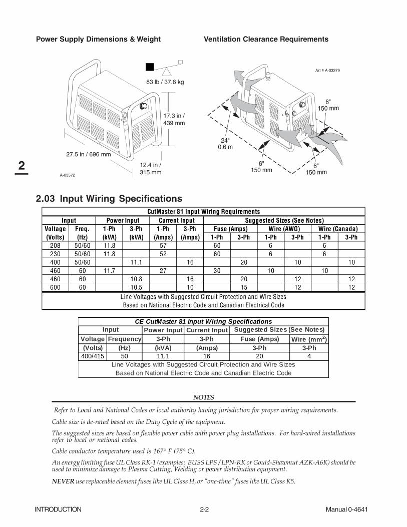
Power Supply Dimensions & Weight Ventilation Clearance Requirements
A-03572
27.5 in / 696 mm
12.4 in / 315 mm
17.3 in /439 mm
83 lb / 37.6 kg
Art # A-03379
6"150 mm
24"0.6 m
6"150 mm
6"150 mm
2.03 Input Wiring Specifications
Input Power Input Current Input Suggested Sizes (See Notes)Voltage Freq. 1-Ph 3-Ph 1-Ph 3-Ph Fuse (Amps) Wire (AWG) Wire (Canada)(Volts) (Hz) (kVA) (kVA) (Amps) (Amps) 1-Ph 3-Ph 1-Ph 3-Ph 1-Ph 3-Ph
208 50/60 11.8 57 60 6 6230 50/60 11.8 52 60 6 6400 50/60 11.1 16 20 10 10460 60 11.7 27 30 10 10460 60 10.8 16 20 12 12600 60 10.5 10 15 12 12
Line Voltages with Suggested Circuit Protection and Wire SizesBased on National Electric Code and Canadian Electrical Code
CutMaster 81 Input Wiring Requirements
Power Input Current InputVoltage Frequency 3-Ph 3-Ph Fuse (Amps) Wire (mm2)(Volts) (Hz) (kVA) (Amps) 3-Ph 3-Ph
400/415 50 11.1 16 20 4
Input Suggested Sizes (See Notes)
Line Voltages with Suggested Circuit Protection and Wire SizesBased on National Electric Code and Canadian Electric Code
CE CutMaster 81 Input Wiring Specifications
NOTES
Refer to Local and National Codes or local authority having jurisdiction for proper wiring requirements.
Cable size is de-rated based on the Duty Cycle of the equipment.
The suggested sizes are based on flexible power cable with power plug installations. For hard-wired installationsrefer to local or national codes.
Cable conductor temperature used is 167° F (75° C).
An energy limiting fuse UL Class RK-1 (examples: BUSS LPS / LPN-RK or Gould-Shawmut AZK-A6K) should beused to minimize damage to Plasma Cutting, Welding or power distribution equipment.
NEVER use replaceable element fuses like UL Class H, or "one-time" fuses like UL Class K5.

Manual 0-4641 2-3 INTRODUCTION
2
2.04 Power Supply Features
Art # A-04214
Input Power Cord
Gas Inlet Port
Gas Pressure Regulator / Filter Assembly
Gas Pressure Gauge
CPC Connector forThermal Dynamics CNC Controller
Knockout for AlternateCNC Controller Wire Harness
Art # A-04507
Work Cableand Clamp
Handle and Leads Wrap
Torch Leads Receptacle
Control Panel
INTRODUCTION 2-4 Manual 0-4641
2
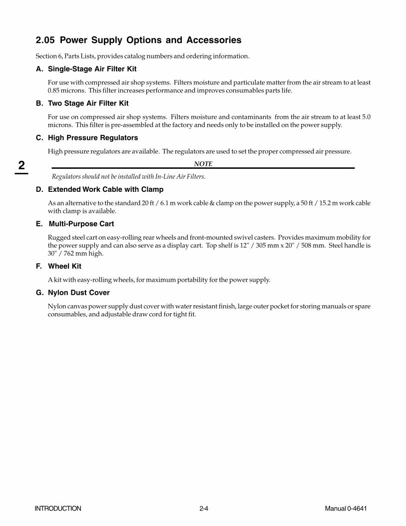
2.05 Power Supply Options and Accessories
Section 6, Parts Lists, provides catalog numbers and ordering information.
A. Single-Stage Air Filter Kit
For use with compressed air shop systems. Filters moisture and particulate matter from the air stream to at least0.85 microns. This filter increases performance and improves consumables parts life.
B. Two Stage Air Filter Kit
For use on compressed air shop systems. Filters moisture and contaminants from the air stream to at least 5.0microns. This filter is pre-assembled at the factory and needs only to be installed on the power supply.
C. High Pressure Regulators
High pressure regulators are available. The regulators are used to set the proper compressed air pressure.
NOTE
Regulators should not be installed with In-Line Air Filters.
D. Extended Work Cable with Clamp
As an alternative to the standard 20 ft / 6.1 m work cable & clamp on the power supply, a 50 ft / 15.2 m work cablewith clamp is available.
E. Multi-Purpose Cart
Rugged steel cart on easy-rolling rear wheels and front-mounted swivel casters. Provides maximum mobility forthe power supply and can also serve as a display cart. Top shelf is 12" / 305 mm x 20" / 508 mm. Steel handle is30" / 762 mm high.
F. Wheel Kit
A kit with easy-rolling wheels, for maximum portability for the power supply.
G. Nylon Dust Cover
Nylon canvas power supply dust cover with water resistant finish, large outer pocket for storing manuals or spareconsumables, and adjustable draw cord for tight fit.
Manual 0-4641 2-5 INTRODUCTION
2
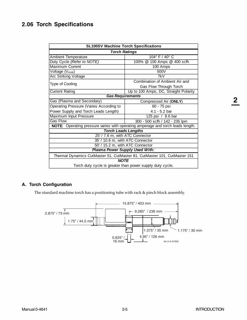
2.06 Torch Specifications
Ambient Temperature 104° F / 40° CDuty Cycle (Refer to NOTE) 100% @ 100 Amps @ 400 scfhMaximum Current 100 AmpsVoltage (Vpeak) 500VArc Striking Voltage 7kV
Type of Cooling Combination of Ambient Air and Gas Flow Through Torch
Current Rating Up to 100 Amps, DC, Straight Polarity
Gas (Plasma and Secondary) Compressed Air (ONLY)Operating Pressure (Varies According to Power Supply and Torch Leads Length)
60 - 75 psi4.1 - 5.2 bar
Maximum Input Pressure 125 psi / 8.6 barGas Flow 300 - 500 scfh / 142 - 235 lpm
SL100SV Machine Torch Specifications
Gas Requirements
Torch Leads LengthsNOTE: Operating pressure varies with operating amperage and torch leads length.
Torch duty cycle is greater than power supply duty cycle.
Plasma Power Supply Used With:Thermal Dynamics CutMaster 51, CutMaster 81, CutMaster 101, CutMaster 151
Torch Ratings
25' / 7.6 m, with ATC Connector 35' / 10.6 m, with ATC Connector50' / 15.2 m, with ATC Connector
NOTE
A. Torch Configuration
The standard machine torch has a positioning tube with rack & pinch block assembly.
Art # A-07402
1.75" / 44.5 mm
1.375" / 35 mm
15.875" / 403 mm
0.625" /16 mm
4.95" / 126 mm
1.175" / 30 mm
9.285" / 236 mm2.875” / 73 mm

INTRODUCTION 2-6 Manual 0-4641
2
B. Torch Connector Dimensions
8.5" / 216 mm
5.375" / 137 mm
1.9" / 50 mm
Art # A-04056
C. Torch Parts
Start Cartridge, Electrode, Tip, Shield Cup Body, Shield Cap
D. Parts - In - Place (PIP)
Torch Head has built - in switch
12 vdc circuit rating
E. Direct Contact Hazard
For exposed tip the recommended standoff is 3/16 inches / 4.7 mm.
2.07 Torch Options and Accessories
These items can adapt a standard system to a particular application or further enhance performance (refer to Section 6for ordering information).
• Spare Parts Kits - Various kits containing replacement consumable torch parts.
• Pinion Assembly (for machine torches)
• Leather Leads Covers
Manual 0-4641 2-7 INTRODUCTION
2
2.08 Introduction to Plasma
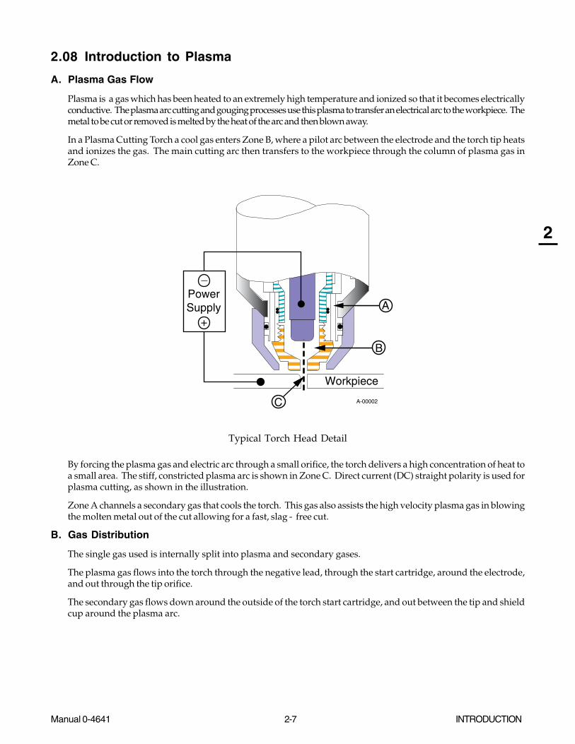
A. Plasma Gas Flow
Plasma is a gas which has been heated to an extremely high temperature and ionized so that it becomes electricallyconductive. The plasma arc cutting and gouging processes use this plasma to transfer an electrical arc to the workpiece. Themetal to be cut or removed is melted by the heat of the arc and then blown away.
In a Plasma Cutting Torch a cool gas enters Zone B, where a pilot arc between the electrode and the torch tip heatsand ionizes the gas. The main cutting arc then transfers to the workpiece through the column of plasma gas inZone C.
������
���
��
����
A-00002
Workpiece
PowerSupply
+
_
C
B
A
Typical Torch Head Detail
By forcing the plasma gas and electric arc through a small orifice, the torch delivers a high concentration of heat toa small area. The stiff, constricted plasma arc is shown in Zone C. Direct current (DC) straight polarity is used forplasma cutting, as shown in the illustration.
Zone A channels a secondary gas that cools the torch. This gas also assists the high velocity plasma gas in blowingthe molten metal out of the cut allowing for a fast, slag - free cut.
B. Gas Distribution
The single gas used is internally split into plasma and secondary gases.
The plasma gas flows into the torch through the negative lead, through the start cartridge, around the electrode,and out through the tip orifice.
The secondary gas flows down around the outside of the torch start cartridge, and out between the tip and shieldcup around the plasma arc.

INTRODUCTION 2-8 Manual 0-4641
2
C. Pilot Arc
When the torch is started a pilot arc is established between the electrode and cutting tip. This pilot arc creates apath for the main arc to transfer to the work.
D. Main Cutting Arc
DC power is also used for the main cutting arc. The negative output is connected to the torch electrode through thetorch lead. The positive output is connected to the workpiece via the work cable and to the torch through a pilotwire.
E. Parts - In - Place (PIP)
The torch leads include a ‘Parts - In - Place’ (PIP) circuit. When the torch shield cup is properly installed, it closesa switch. The torch will not operate if this switch is open.
A-03504
PIP Switch Shield CupTo ControlCable Wiring
Parts - In - Place Circuit Diagram

Manual 0-4641 3-1 INSTALLATION
3
SECTION 3: INSTALLATION
3.01 Unpacking
1. Use the packing lists to identify and account for each item.
2. Inspect each item for possible shipping damage. If damage is evident, contact your distributor and / or shippingcompany before proceeding with the installation.
3. Record Power Supply and Torch model and serial numbers, purchase date and vendor name, in the informationblock at the front of this manual.
3.02 Lifting Options
The Power Supply includes a handle for hand lifting only. Be sure unit is lifted and transported safely and securely.
WARNINGS
Do not touch live electrical parts.
Disconnect input power cord before moving unit.
FALLING EQUIPMENT can cause serious personal injury and can damage equipment.
HANDLE is not for mechanical lifting.
• Only persons of adequate physical strength should lift the unit.
• Lift unit by the handle, using two hands. Do not use straps for lifting.
• Use optional wheel kit, cart or similar device of adequate capacity to move unit.
• Place unit on a proper skid and secure in place before transporting with a fork lift or other vehicle.

INSTALLATION 3-2 Manual 0-4641
3
3.03 Primary Input Power Connections
CAUTION
Check your power source for correct voltage before plugging in or connecting the unit. The primary powersource, fuse, and any extension cords used must conform to local electrical code and the recommended circuitprotection and wiring requirements as specified in Section 2.03.
A. Connections to 208 / 230-Volt Power
The 208 / 230-Volt power supply includes a factory-installed input power cable and plug.
1. Check your power source for correct voltage before plugging in the unit.
2. Connect the input power cable (or close the main disconnect switch) to supply power to the system.
CAUTION
The primary power source and power cable must conform to local electrical code and the recommended circuitprotection and wiring requirements (refer to table in Section 2.03).
B. Connections to 400-Volt, 415-Volt, 460-Volt, or 600-Volt Three-Phase Power
These Power Supplies are equipped with a four-conductor input power cable for three-phase input power. The 460-Volt PowerSupplies will accept 460-VAC, Single-Phase input power with a change of input power cable.
1. Check your power source for correct voltage before plugging in the unit.
2. The input cable's outer covering is stripped back at the factory to expose the individual wires at the free end of the cable.
3. Connect the ends of the individual wires to a customer supplied plug or main disconnect as follows:
CAUTION
The primary power source and power cable must conform to local electrical code and the recommended circuitprotection and wiring requirements (refer to table in Section 2 ). All the input cable wires must be connected forthree-phase operation.
• Green / Yellow wire to Ground.
• Remaining wires to L1, L2, L3 input.
4. Connect the input power cable (or close the main disconnect switch) to supply power to the system.

Manual 0-4641 3-3 INSTALLATION
3
C. Connections to 460-Volt Single - Phase Power
The 460-Volt Power Supplies will accept 460-VAC, Single-Phase input power with a change of input power cable.
1. Remove the Power Supply cover per section 5.09-A.
2. Disconnect the original input power cable from the main input contactor and the chassis ground connection.
3. Loosen the through-hole protector on the back panel of the power supply. Pull the original power cable out of the powersupply.
4. Pass a customer-supplied, three-conductor input power cable through the access opening in the back panel of the powersupply. Refer to Section 2 for power cable specifications.
CAUTION
The primary power source and power cable must conform to local electrical code and the recommended circuitprotection and wiring requirements (refer to table in Section 2.03).
5. Strip back the insulation on the individual wires.
6. Connect to main input contactor as follows:
• Line 1 wire to terminal L1.
• Line 3 wire to terminal L3.
7. Connect the ground wire to Ground (Earth). The Ground wire connection requires a ring terminal.
8. Tighten the through-hole protector to secure the power cable.
A-03041
L1
L3
Ground Wirewith RingTerminal
Main Input Contactor
Input Cable
L1 L2 L3
Input Power Connections, 460 VAC, Single-Phase
9. Replace the Power Supply cover.
10. Connect the input power cable (or close the main disconnect switch) to supply power to the system.

INSTALLATION 3-4 Manual 0-4641
3
3.04 Gas Connections
A. Connecting Gas Supply to Unit
Use only compressed air with this power supply.
An in-line pneumatic dryer & evaporator type air filter, capable of filtering to at least 5 microns, is required when using air from acompressor. This type filter will insure that moisture, oil, dirt, chips, rust particles, and other contaminants from the supply hosedo not enter the torch. For highly automated applications, a refrigerated drier may be used.
The connection is the same for compressed air from a compressor from high pressure cylinders. Refer to subsection 3.4-B or 3.4-C if an additional air line filter is to be installed.
1. Connect the air line to the inlet port. The illustration shows typical fittings as an example. Other fittings can beused.
NOTE
For a secure seal, apply thread sealant to the fitting threads, according to manufacturer's instructions. Do not useTeflon tape as a thread sealer, as small particles of the tape may break off and block the small air passages in the torch.
Art # A-02999
Hose Clamp
1/4 NPT to 1/4"(6mm) Fitting
Regulator/FilterAssembly
Inlet Port
Gas SupplyHose
Bowl
Air Connection to Inlet Port

Manual 0-4641 3-5 INSTALLATION
3
B. Optional Air Filters
1. Connect the Filter as illustrated. Use only Synflex or equivalent grade hose. The illustrations show typical fittings as anexample.
NOTE
For a secure seal, apply thread sealant to the fitting threads, according to the maker's instructions. Do Not useTeflon tape as a thread sealer, as small particles of the tape may break off and block the small air passages in thetorch. Connect as follows:
Art # A-03000
Regulator/FilterAssembly
Inlet Port
Bowl
1/4 NPT Hose Fitting
1/4" (6 mm) Gas Supply Hose
Hose Clamp
Art # A-03004
Regulator/FilterAssembly
HoseClamp
1/4 NPT Hose Fitting
1/4" (6 mm) Gas Supply Hose)
2-Stage FilterInlet Port (IN)
Outlet Port(OUT)
Regulator Inlet Port
Two Stage Filter
Assembly
Optional Single-Stage Filter Installation Optional Two-Stage Filter Installation

INSTALLATION 3-6 Manual 0-4641
3
D. Using High Pressure Air Cylinders
When using high pressure air cylinders as the air supply:
1. Refer to the manufacturer’s specifications for installation and maintenance procedures for high pressure regula-tors.
2. Examine the cylinder valves to be sure they are clean and free of oil, grease or any foreign material. Briefly openeach cylinder valve to blow out any dust which may be present.
3. The cylinder must be equipped with an adjustable high-pressure regulator capable of outlet pressures up to 100 psi (6.9 bar)maximum and flows of at least 500 scfh (236 lpm).
4. Connect supply hose to the cylinder.
NOTE
Pressure should be set at 100 psi (6.9 bar) at the high pressure cylinder regulator.
Supply hose must be at least 1/4 inch (6 mm) I.D.
For a secure seal, apply thread sealant to the fitting threads, according to manufacturer's instructions. Do Not useTeflon tape as a thread sealer, as small particles of the tape may break off and block the small air passages in the torch.

Manual 0-4641 3-7 INSTALLATION
3
3.05 Torch Connections
If necessary, connect the torch to the Power Supply. Connect only the Thermal Dynamics model SL100 Torch (with ATCconnector) to this power supply. Maximum torch leads length is 50 feet / 15.2 m.
WARNING
Disconnect primary power at the source before connecting the torch.
1. Align the ATC male connector (on the torch lead) with the female receptacle. Push the male connector into thefemale receptacle. The connectors should push together with a small amount of pressure.
2. Secure the connection by turning the locking nut clockwise until it clicks. DO NOT use the locking nut to pullthe connection together. Do not use tools to secure the connection.
3. The system is ready for operation.
Torch Leads
Art # A-06755
1
2
ATC Male Connector
ATC Female Receptacle (Panel Mounted)

INSTALLATION 3-8 Manual 0-4641
3
Connecting the Torch to the Power Supply
B. Check Air Quality
To test the quality of air:
1. Put the ON / OFF switch in the ON (up) position.
2. Put the RUN / RAPID AUTO RESTART / SET switch in the SET (down) position.
3. Place a welding filter lens in front of the torch and turn on the air. Any oil or moisture in the air will be visible on the lens.Do not start an arc!
Art # A-03592
A
20
40
601 2
Manual 0-4641 3-9 INSTALLATION
3
3.06 Torch Installation
WARNING
Disconnect primary power at the source before disassembling the torch or torch leads.
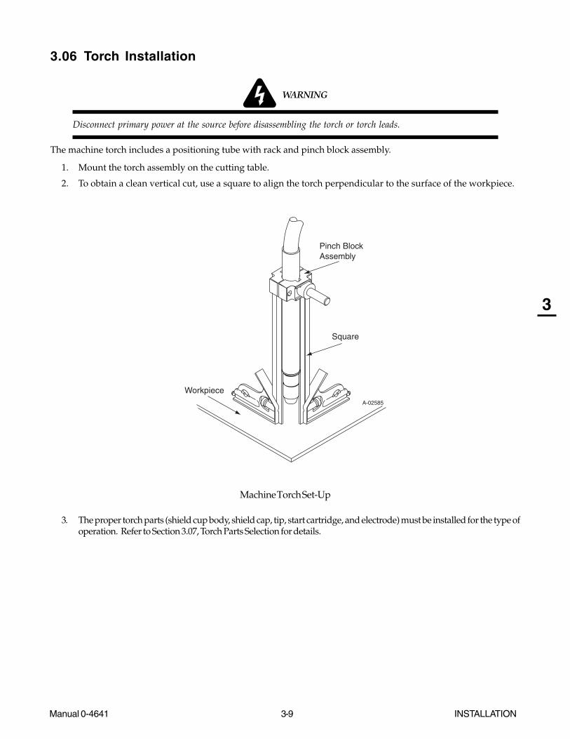
The machine torch includes a positioning tube with rack and pinch block assembly.
1. Mount the torch assembly on the cutting table.
2. To obtain a clean vertical cut, use a square to align the torch perpendicular to the surface of the workpiece.
A-02585
Workpiece
Square
Pinch BlockAssembly
Machine Torch Set-Up
3. The proper torch parts (shield cup body, shield cap, tip, start cartridge, and electrode) must be installed for the type ofoperation. Refer to Section 3.07, Torch Parts Selection for details.

INSTALLATION 3-10 Manual 0-4641
3
3.07 Torch Parts Selection
1. Check the torch for proper consumable parts. The parts supplied in the torch may not be correct for the operator's chosenamperage level. The torch parts must correspond with the type of operation.
Art # A-04173
Electrode
Start Cartridge
Tip
Ohmic Clip (If Installed)
Torch Head
Shield Cup Body
Shield CapDeflector
Manual 0-4641 3-11 INSTALLATION
3
3.08 Power Supply Connection to SC-11 Standoff Control
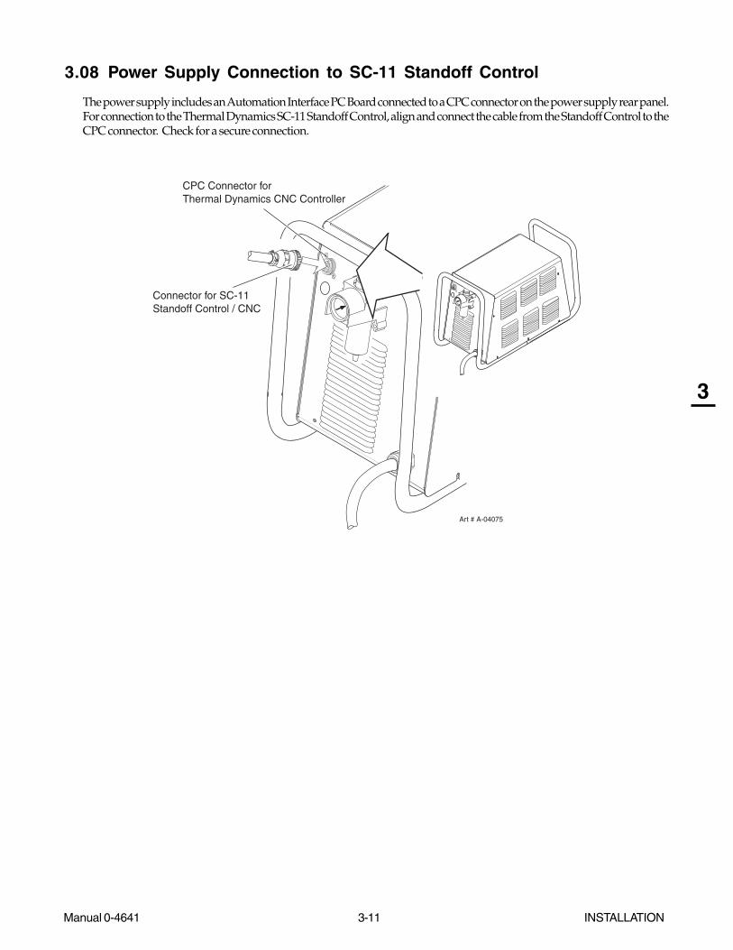
The power supply includes an Automation Interface PC Board connected to a CPC connector on the power supply rear panel.For connection to the Thermal Dynamics SC-11 Standoff Control, align and connect the cable from the Standoff Control to theCPC connector. Check for a secure connection.
CPC Connector forThermal Dynamics CNC Controller
Art # A-04075
Connector for SC-11Standoff Control / CNC
INSTALLATION 3-12 Manual 0-4641
3
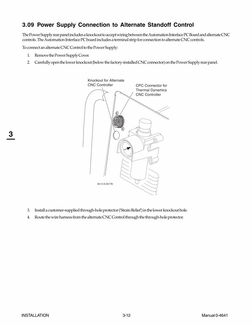
3.09 Power Supply Connection to Alternate Standoff Control
The Power Supply rear panel includes a knockout to accept wiring between the Automation Interface PC Board and alternate CNCcontrols. The Automation Interface PC board includes a terminal strip for connection to alternate CNC controls.
To connect an alternate CNC Control to the Power Supply:
1. Remove the Power Supply Cover.
2. Carefully open the lower knockout (below the factory-installed CNC connector) on the Power Supply rear panel.
CPC Connector forThermal Dynamics CNC Controller
Art # A-04178
Knockout for AlternateCNC Controller
3. Install a customer-supplied through-hole protector ('Strain Relief') in the lower knockout hole.
4. Route the wire harness from the alternate CNC Control through the through-hole protector.

Manual 0-4641 3-13 INSTALLATION
3
5. Connect the wire harness from the alternate CNC Control to the 20-position terminal strip (labeled 'J2') on the AutomationInterface PC Board. Refer to the illustration.
a. For divided voltage output, connect to terminals J2-11 (negative) and J2-9 (positive) on the Interface PC Board..
b. For raw arc voltage, connect to terminals E2 (positive) and E1 (negative) on the Output Power PC Board.
NOTE
There is no need to disconnect the factory-installed wire harness from the J4 terminal strip.
39 5 4 12678101319 15 14 111216171820
Art # A-04149
Torc
h Switc
h
(Pos
itive)
Torc
h Switc
h (N
egat
ive)
OK to M
ove
OK to M
ove
Divide
d Out
put (
Positiv
e)
Divide
d Out
put (
Negat
ive)
Logic
Com
mon
Open
Open
Open
Open
Open
Open
Open
Open
Arc Vo
lts -
Positiv
e (P
ropr
ietar
y)
Arc Vo
lts N
egat
ive -
(Pro
priet
ary)
Remot
e Cur
rent
Con
trol (
Option
al)
Remot
e Cur
rent
Con
trol (
Option
al)
Remot
e Cur
rent
Con
trol (
Option
al)
To Main PC Board Terminal J27-3
To Main PC Board Terminal J27-1
To Main PC Board Terminal J27-2
Installed only with Optional Remote Current Control
Terminal Block J2
E2 (+)E1(-)
Automation Interface PC Board
Output Power PC Board
Raw Arc Voltage Connection Points
Alternate CNC Controller Connections to Automation Interface Board
6. Tighten the through-hole protector ('strain relief') to secure the CNC cable to the power supply.

INSTALLATION 3-14 Manual 0-4641
3
3.10 Automation Interface PC Board Set-up
The Automation Interface PC board includes switches that must be set to adapt the Interface Board to the automation systembeing used.
NOTE
The switches are factory-set for the Thermal Dynamics SC-11 Standoff Control.
For operation with any other CNC equipment, refer to the CNC system documents to determine the division factor the CNCsystem requires. Proceed as follows:
1. Set the interface control board switches as indicated in the appropriate chart in the Appendix pages. The division factorsare listed in the right-hand column of each chart.
Automation Interface PC Board
Art # A-03902
Pilot PCBoard
Output PowerPC Board
Automation Interface PC Board
Art # A-03757
Switches
8 7 6 5 4 3 2 1
2. Re-install the Power Supply cover.
Manual 0-4641 3-15 INSTALLATION
3
3.11 Optional Remote Current Control Harness Installation
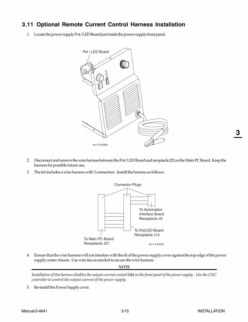
1. Locate the power supply Pot/LED Board just inside the power supply front panel.
Art # A-03964
Pot / LED Board
2. Disconnect and remove the wire harness between the Pot/LED Board and receptacle J22 on the Main PC Board. Keep theharness for possible future use.
3. The kit includes a wire harness with 3 connectors. Install the harness as follows:
To Pot/LED BoardReceptacle J14
To Automation Interface BoardReceptacle J3
To Main PC BoardReceptacle J27
Connector Plugs
Art # A-03945
4. Ensure that the wire harness will not interfere with the fit of the power supply cover against the top edge of the powersupply center chassis. Use wire ties as needed to secure the wire harness.
NOTE
Installation of this harness disables the output current control (A) on the front panel of the power supply. Use the CNCcontroller to control the output current of the power supply.
5. Re-install the Power Supply cover.

INSTALLATION 3-16 Manual 0-4641
3 This Page Left Blank

Manual 0-4641 4-1 OPERATION
4
SECTION 4: OPERATION
4.01 Product Features
A. Power Supply Front Panel Controls and Indicators
(A) Output Current Control
Sets the desired output current. At output settingsover 40 Amps, the power supply automatically re-duces output current to 40 Amps if the torch tiptouches the workpiece.
ON / OFF Switch
Controls input power to the power supply.
is ON, is OFF.
RUN / RAPID AUTO RESTART / SET Switch
RUN (up) position is for general torch operation.
RAPID AUTO RESTART (middle) position is for an uninterrupted restart, when cutting
expanded metal or in trimming operations.
SET (down) position is for setting gas pressure and purging lines.
AC Indicator
Steady light indicates power supply is ready foroperation. Blinking light indicates unit is in pro-tective interlock mode. Shut unit off, shut off ordisconnect input power, correct the fault, and re-start the unit. Refer to Section 5 for details.
TEMP Indicator
Indicator is normally OFF. Indicator is ONwhen internal temperature exceeds normallimits. Shut unit OFF; let the unit cool beforecontinuing operation.
GAS Indicator
Indicator is ON when minimum input gaspressure for power supply operation ispresent. Minimum pressure for power sup-ply operation is not sufficient for torch op-eration.
DC Indicator
Indicator is ON when DC output circuit isactive.
Art # A-03743
A
20
40
60
OPERATION 4-2 Manual 0-4641
4
4.02 Preparations For Operating
Perform the following steps at the start of each operating session:
WARNING
Disconnect primary power at the source before assembling or disassembling power supply, torch parts, or torch andleads assemblies.
A. Torch Parts Selection
Check the torch for proper assembly and appropriate torch parts. The torch parts must correspond with the type ofoperation, and with the amperage output of this Power Supply (80 amps maximum).
B. Torch Connection
Check that the torch is properly connected. Only Thermal Dynamics model SL100 Torches may be connected tothis Power Supply.
C. Check Primary Input Power Source
1. Check the power source for proper input voltage. Make sure the input power source meets the power re-quirements for the unit per Section 2, Specifications.
2. Connect the input power cable (or close the main disconnect switch) to supply power to the system.
D. Gas Selection
Ensure compressed air source meets requirements (refer to Section 3.4). Check connections and turn gas supply on.
Place the ON - OFF Switch on the Power Supply to the ON position. If the Run - Rapid Auto Restart - Set switch is in SETposition, gas will flow. If the switch is in RUN or Rapid Auto Restart position there will be no gas flow.
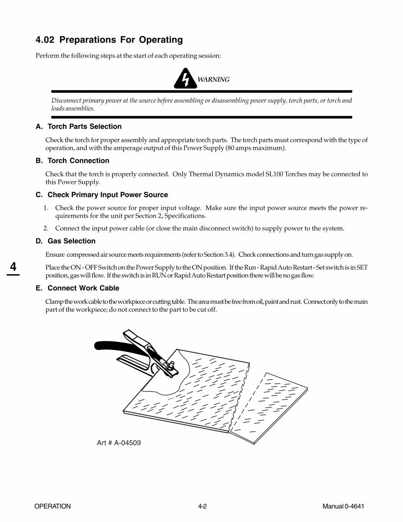
E. Connect Work Cable
Clamp the work cable to the workpiece or cutting table. The area must be free from oil, paint and rust. Connect only to the mainpart of the workpiece; do not connect to the part to be cut off.
Art # A-04509

Manual 0-4641 4-3 OPERATION
4
F. Power On
Place the Power Supply ON / OFF switch to the ON (up) position. AC indicator turns on. Gas indicator
turns on if there is sufficient gas pressure for power supply operation.
NOTE
Minimum pressure for power supply operation is lower than minimum for torch operation.
Art # A-03594
A
20
40
60
OPERATION 4-4 Manual 0-4641
4
G. Set Operating Pressure
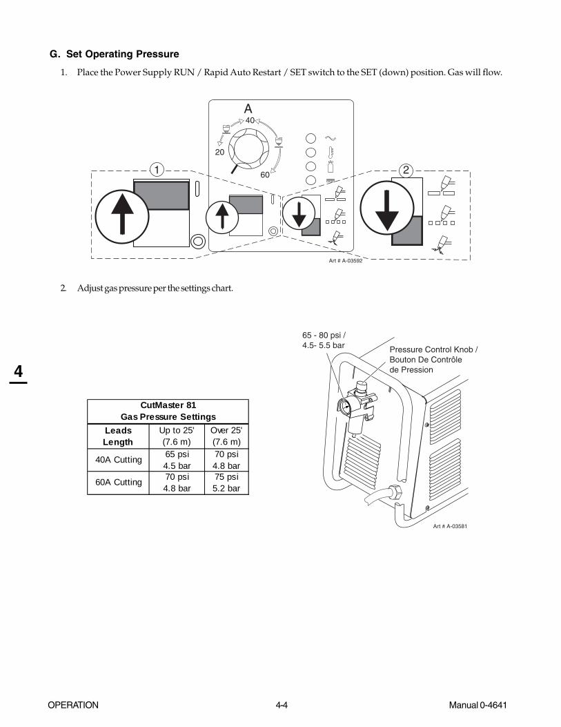
1. Place the Power Supply RUN / Rapid Auto Restart / SET switch to the SET (down) position. Gas will flow.
Art # A-03592
A
20
40
601 2
2. Adjust gas pressure per the settings chart.
Leads Length
Up to 25' (7.6 m)
Over 25' (7.6 m)
40A Cutting 65 psi4.5 bar
70 psi4.8 bar
60A Cutting 70 psi4.8 bar
75 psi5.2 bar
CutMaster 81 Gas Pressure Settings
Art # A-03581
65 - 80 psi / 4.5- 5.5 bar Pressure Control Knob /
Bouton De Contrôle de Pression

Manual 0-4641 4-5 OPERATION
4
H. Select Current Output Level
1. Place RUN / Rapid Auto Restart / SET to RUN (up) or Rapid Auto Restart (center) position. Gas flow stops.
2. Set the current output level, up to 80 amps for standoff cutting. At output settings higher than 40 amps, thepower supply automatically reduces output current to 40 amps if the torch tip contacts the workpiece.
Art # A-03593
A
20
40
60
1
2
I. Cutting Operation
When the torch leaves the workpiece during cutting operations with the RUN / Rapid Auto Restart / SET switch in the RUN(up) position, there is a brief delay in restarting the pilot arc. With the switch in the 'Rapid Auto Restart' (middle) position,when the torch leaves the workpiece the pilot arc restarts instantly, and the cutting arc restarts instantly when the pilot arccontacts the workpiece. Use the 'Rapid Auto Restart' position when cutting expanded metal or gratings, or in trimmingoperations when an uninterrupted restart is desired.
J. Typical Cutting Speeds
Cutting speeds vary according to torch output amperage, the type of material being cut, and operator skill.
Output current setting or cutting speeds may be reduced to allow slower cutting while still producing cuts of excellent quality.
K. Postflow
De-activate the start signal (provided by the CNC Control) to stop the cutting arc. Gas continues to flow for approximately 6seconds. During post - flow, if the user activates start signal, the pilot arc starts. The main arc transfers to the workpiece if thetorch tip is within transfer distance to the workpiece.

OPERATION 4-6 Manual 0-4641
4
4.03 Selection, Inspection and Replacement of Consumable Torch Parts
The type of operation to be done determines the torch parts to be used. Change the torch parts for a different operation asfollows:
WARNINGS
Disconnect primary power to the system before disassembling the torch or torch leads.
DO NOT touch any internal torch parts while the AC indicator light of the Power Supply is ON.
Art # A-04173
Electrode
Start Cartridge
Tip
Ohmic Clip (If Installed)
Torch Head
Shield Cup Body
Shield CapDeflector
Consumable Parts
1. Unscrew and remove the shield cup assembly from the torch head. Inspect the cup for damage. Wipe it clean or replace ifdamaged.
NOTES
The shield cup holds the tip and start cartridge in place.
Slag built up on the shield cup that cannot be removed may affect the performance of the system.

Manual 0-4641 4-7 OPERATION
4
2. Remove the tip. Check for excessive wear (indicated by an elongated or oversized orifice). Clean or replace the tipif necessary.
Good Tip Worn Tip
A-03406
Tip Wear
3. Remove the start cartridge. Check for excessive wear, plugged gas holes, or discoloration. Check the lower endfitting for free motion. Replace if necessary.
Art # A-07168
Spring-Loaded Cylinder at Full Compression
Spring-Loaded Cylinder at Full Extension
1/8” (3 mm)
4. Pull the Electrode straight out of the Torch Head. Check the end of the electrode for excessive wear. Replace theelectrode if wear is greater than 0.062" / 1.5 mm or if the wear is excessively off-center. Refer to the following figure.
Electrode WearArt # A-04057
0.062" (1.5 mm)
Electrode Wear
5. Reinstall the Electrode by pushing it straight into the torch head until it clicks.
6. Reinstall the start cartridge and tip into the torch head.
7. Hand tighten the shield cup until it is seated on the torch head. If resistance is felt when installing the cup, check the threadsbefore proceeding.
NOTE
When the shield cup is properly installed, there is a slight gap between the shield cup and the torch head. Gas ventsthrough this gap as part of normal operation. Do not attempt to force the shield cup to close this gap. Forcing theshield cup against the torch head can damage components.

OPERATION 4-8 Manual 0-4641
4
4.04 Cut Quality
NOTES
Cut quality depends heavily on setup and parameters such as torch standoff, alignment with the workpiece, cuttingspeed, gas pressures, and operator ability.
Cut quality requirements differ depending on application. For instance, nitride build - up and bevel angle may be major factorswhen the surface will be welded after cutting. Dross - free cutting is important when finish cut quality is desired to avoid asecondary cleaning operation. The following cut quality characteristics are illustrated in the following figure:
Kerf WidthCut SurfaceBevel Angle
Top EdgeRounding
Cut SurfaceDrag Lines
DrossBuild-Up
TopSpatter
A-00007
Cut Quality Characteristics
A. Cut Surface
The desired or specified condition (smooth or rough) of the face of the cut.
B. Nitride Build - Up
Nitride deposits can be left on the surface of the cut when nitrogen is present in the plasma gas stream. These buildups maycreate difficulties if the material is to be welded after the cutting process.
C. Bevel Angle
The angle between the surface of the cut edge and a plane perpendicular to the surface of the plate. A perfectlyperpendicular cut would result in a 0° bevel angle.
D. Top - Edge Rounding
Rounding on the top edge of a cut due to wearing from the initial contact of the plasma arc on the workpiece.
E. Bottom Dross Buildup
Molten material which is not blown out of the cut area and resolidifies on the plate. Excessive dross may requiresecondary cleanup operations after cutting.
F. Kerf Width
The width of the cut (or the width of material removed during the cut).
G. Top Spatter (Dross)
Top spatter or dross on the top of the cut caused by slow travel speed, excess cutting height, or cutting tip whose orifice hasbecome elongated.
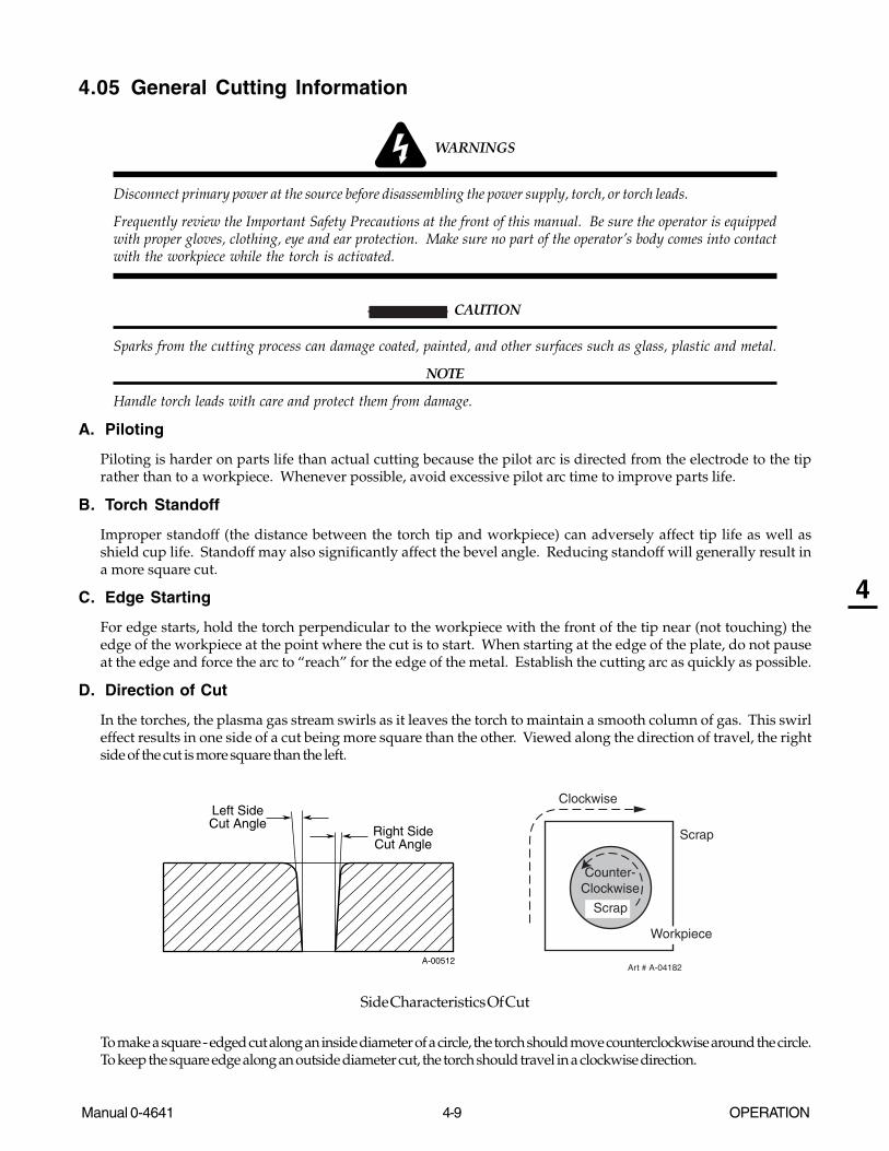
Manual 0-4641 4-9 OPERATION
4
4.05 General Cutting Information
WARNINGS
Disconnect primary power at the source before disassembling the power supply, torch, or torch leads.
Frequently review the Important Safety Precautions at the front of this manual. Be sure the operator is equippedwith proper gloves, clothing, eye and ear protection. Make sure no part of the operator’s body comes into contactwith the workpiece while the torch is activated.
CAUTION
Sparks from the cutting process can damage coated, painted, and other surfaces such as glass, plastic and metal.
NOTE
Handle torch leads with care and protect them from damage.
A. Piloting
Piloting is harder on parts life than actual cutting because the pilot arc is directed from the electrode to the tiprather than to a workpiece. Whenever possible, avoid excessive pilot arc time to improve parts life.
B. Torch Standoff
Improper standoff (the distance between the torch tip and workpiece) can adversely affect tip life as well asshield cup life. Standoff may also significantly affect the bevel angle. Reducing standoff will generally result ina more square cut.
C. Edge Starting
For edge starts, hold the torch perpendicular to the workpiece with the front of the tip near (not touching) theedge of the workpiece at the point where the cut is to start. When starting at the edge of the plate, do not pauseat the edge and force the arc to “reach” for the edge of the metal. Establish the cutting arc as quickly as possible.
D. Direction of Cut
In the torches, the plasma gas stream swirls as it leaves the torch to maintain a smooth column of gas. This swirleffect results in one side of a cut being more square than the other. Viewed along the direction of travel, the rightside of the cut is more square than the left.
Right SideCut Angle
Left SideCut Angle
A-00512
Scrap
Clockwise
Counter-Clockwise
Art # A-04182
Workpiece
Scrap
Side Characteristics Of Cut
To make a square - edged cut along an inside diameter of a circle, the torch should move counterclockwise around the circle.To keep the square edge along an outside diameter cut, the torch should travel in a clockwise direction.
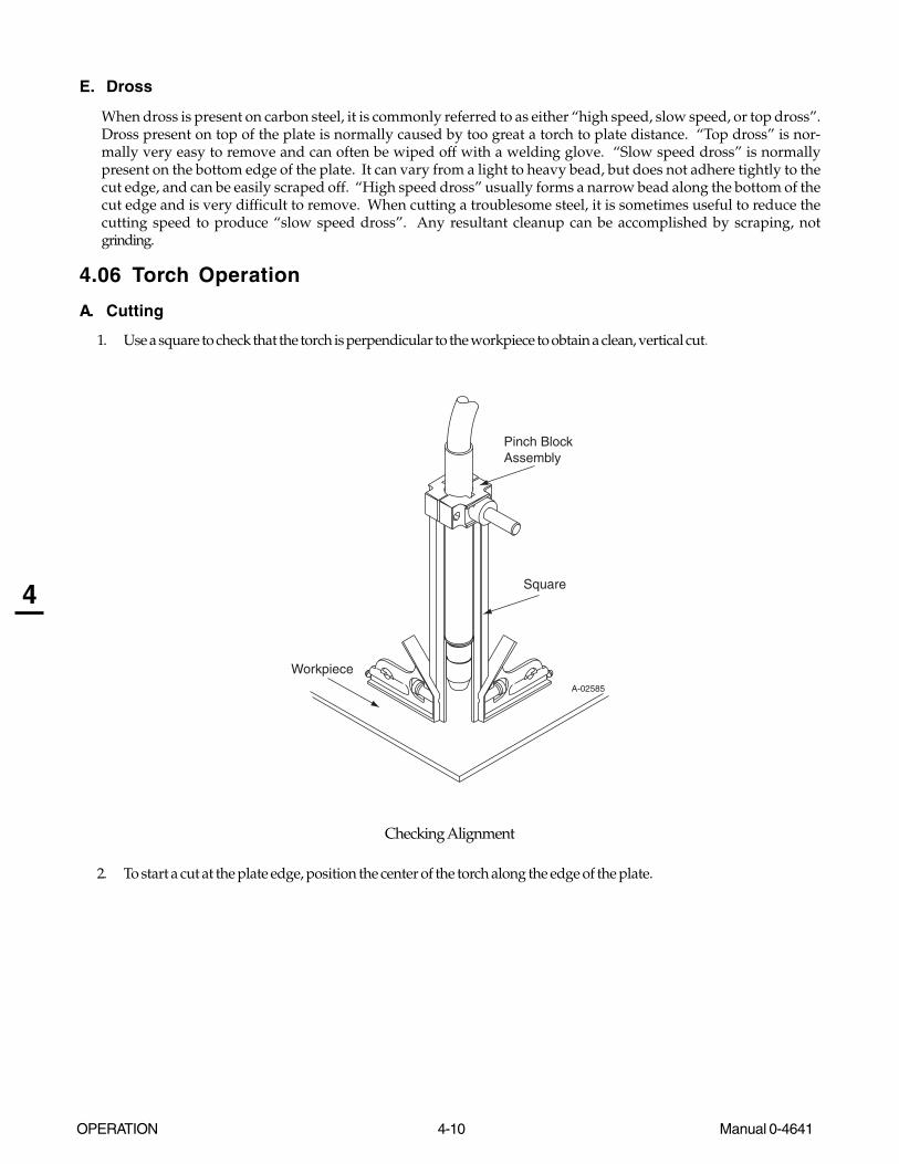
OPERATION 4-10 Manual 0-4641
4
E. Dross
When dross is present on carbon steel, it is commonly referred to as either “high speed, slow speed, or top dross”.Dross present on top of the plate is normally caused by too great a torch to plate distance. “Top dross” is nor-mally very easy to remove and can often be wiped off with a welding glove. “Slow speed dross” is normallypresent on the bottom edge of the plate. It can vary from a light to heavy bead, but does not adhere tightly to thecut edge, and can be easily scraped off. “High speed dross” usually forms a narrow bead along the bottom of thecut edge and is very difficult to remove. When cutting a troublesome steel, it is sometimes useful to reduce thecutting speed to produce “slow speed dross”. Any resultant cleanup can be accomplished by scraping, notgrinding.
4.06 Torch Operation
A. Cutting
1. Use a square to check that the torch is perpendicular to the workpiece to obtain a clean, vertical cut.
A-02585
Workpiece
Square
Pinch BlockAssembly
Checking Alignment
2. To start a cut at the plate edge, position the center of the torch along the edge of the plate.

Manual 0-4641 4-11 OPERATION
4
B. Travel Speed
Proper travel speed is indicated by the trail of the arc which is seen below the plate. The arc can be one of thefollowing:
1. Straight Arc
A straight arc is perpendicular to the workpiece surface. This arc is generally recommended for the best cutusing air plasma on stainless or aluminum.
2. Leading Arc
The leading arc is directed in the same direction as torch travel. A five degree leading arc is generally recom-mended for air plasma on mild steel.
3. Trailing Arc
The trailing arc is directed in the opposite direction as torch travel.
Standoff Distance
Straight Arc
Trailing Arc
Leading Arc
Direction of Torch Travel
A-02586
Machine Torch Operation
For optimum smooth surface quality, the travel speed should be adjusted so that only the leading edge of the arccolumn produces the cut. If the travel speed is too slow, a rough cut will be produced as the arc moves from side toside in search of metal for transfer.
Travel speed also affects the bevel angle of a cut. When cutting in a circle or around a corner, slowing down thetravel speed will result in a squarer cut.
OPERATION 4-12 Manual 0-4641
4
C. Piercing With Machine Torch
To pierce with a machine torch, the arc should be started with the torch positioned as high as possible above theplate while allowing the arc to transfer and pierce. This standoff helps avoid having molten metal blow backonto the front end of the torch.
When operating with a cutting machine, a pierce or dwell time is required. Torch travel should not be enabled until the arcpenetrates the bottom of the plate. As motion begins, torch standoff should be reduced to the recommended 1/8 - 1/4 inch (3-6 mm) distance for optimum speed and cut quality. Clean spatter and scale from the shield cup and the tip as soon as possible.Spraying or dipping the shield cup in anti - spatter compound will minimize the amount of scale which adheres to it.
4.07 Cutting Parameters
Cutting speed depends on material, thickness, and other factors. These may have an impact on system performance:
• Torch parts wear
• Air quality
• Line voltage fluctuations
• Torch standoff height
• Proper work cable connection

Manual 0-4641 4-13 OPERATION
4
Cut Quality on Various Materials andThicknesses
The following table defines the cut quality on various mate-rials and thicknesses:
Cut Quality on Various Materials
Material Type of Type of CutThickness Material Gas Characteristics
Gageto
3/4 inch( 19 mm )
Good - Excellent
Good
Good
Carbon Steel
Stainless
Aluminum
Air
Air
Air
Description of Cut Characteristics:
Excellent - Minimum bevel (0 - 4°), minimum kerf (2 x tip orifice diameter), little or no dross, smooth cut surface.
Good - Slight bevel (0 - 10°), slightly wider kerf (2-1/2 x tiporifice diameter), some dross (easily removed), medium -smooth cut surface, slight top edge rounding.
4.08 Cutting Specifications
Cutting RangeMaterial Most Metals
Up to 3/4 inch - 19 mmSpeed 11 ipm / 0.28 mpm
Pierce RatingMaterial Carbon Steel
Thickness 3/8 inch - 9.5 mmTransfer Distance 3/8 inch - 9.5 mmGas Requirement
Type Gas Air
Operating Pressure 65 psi / 4.5 bar
Max Input Pressure 125 psi / 8.6 barCutting & Gouging
Total Flow 350 scfh / 165 lpm
Torch Specifications ForCutMaster 81 Power Supplies

OPERATION 4-14 Manual 0-4641
4
4.09 Cutting Speed Chart: Mild Steel, SL100 Torch with Exposed Tip
NOTES
* Gas pressure shown is for torches with leads up to 25' / 7.6 m long. For 50' / 15.2 m leads, increase pressure by 5 psi / 0.34 bar.
This information represents realistic expectations using recommended practices and well - maintained systems.Actual speeds may vary up to 50% from those shown.
Electrode Start Cartridge Tip Shield Cup Body Shield Cap, Deflector 9-8215 9-8213 9-8237 9-8243
Art # A-04203
Torch: SL100 with Exposed Tip and DeflectorPower Supply: CutMaster 81 Automated
Tip Current PlasmaPress.*
Pierce Time
Arc voltage
In GA mm Cat. # Amps PSI In mm SEC Volts in mm IPM mm/min0.036 20 0.91 8-8208 40 65 0.188 4.8 0.00 96 0.19 4.80 341 8661.40.051 1.30 8-8208 40 65 0.188 4.8 0.00 97 0.19 4.80 300 76200.060 16 1.52 8-8208 40 65 0.188 4.8 0.10 98 0.19 4.80 265 67310.075 14 1.91 8-8208 40 65 0.188 4.8 0.30 100 0.19 4.80 190 48260.135 10 3.43 8-8208 40 65 0.188 4.8 0.40 101 0.19 4.80 120 30480.141 3.58 8-8208 40 65 0.188 4.8 0.50 102 0.19 4.80 112 2844.80.188 4.78 8-8208 40 65 0.188 4.8 0.60 107 0.19 4.80 60 15240.250 6.35 8-8208 40 65 0.188 4.8 1.00 111 0.19 4.80 40 10160.375 9.53 8-8208 40 65 NR NR NR 119 0.19 4.80 19.7 500.380.500 12.70 8-8208 40 65 NR NR NR 123 0.19 4.80 11.1 281.940.625 15.88 8-8208 40 65 NR NR NR 127 0.19 4.80 6 152.40.060 16 1.57 9-8210 60 70 0.188 4.8 0.00 110 0.19 4.80 293 7442.20.075 14 1.91 9-8210 60 70 0.188 4.8 0.10 110 0.19 4.80 288 7315.20.120 11 3.05 9-8210 60 70 0.188 4.8 0.10 111 0.19 4.80 273 6934.20.135 10 3.43 9-8210 60 70 0.188 4.8 0.10 111 0.19 4.80 215 54610.141 3.58 9-8210 60 70 0.188 4.8 0.15 112 0.19 4.80 177.6 4511.040.188 4.78 9-8210 60 70 0.188 4.8 0.20 114 0.19 4.80 137 3479.80.250 6.35 9-8210 60 70 0.188 4.8 0.30 116 0.19 4.80 82.4 2092.960.375 9.53 9-8210 60 70 0.188 4.8 0.50 118 0.19 4.80 42.4 1076.960.500 12.70 9-8210 60 70 0.188 4.8 0.75 119 0.19 4.80 26.3 668.020.625 15.88 9-8210 60 70 NR NR NR 127 0.19 4.80 17.4 441.960.750 19.05 9-8210 60 70 NR NR NR 126 0.19 4.80 16 406.41.000 25.40 9-8210 60 70 NR NR NR 128 0.19 4.80 12 304.8
Material: Mild SteelTable: DryGas: Compressed Air
RecommendedTravel Speed
Stand-offHeightPierce HeightMaterial thickness

Manual 0-4641 4-15 OPERATION
4
4.10 Cutting Speed Charts: Stainless Steel, SL100 Torch with Exposed Tip
NOTES
*Gas pressure shown is for torches with leads up to 25' / 7.6 m long. For 50' / 15.2 m leads, increase pressure by 5 psi / 0.34 bar.
This information represents realistic expectations using recommended practices and well - maintained systems.Actual speeds may vary up to 50% from those shown.
Electrode Start Cartridge Tip Shield Cup Body Shield Cap, Deflector 9-8215 9-8213 9-8237 9-8243
Art # A-04203
Table: DryGas: Compressed Air
Material thickness Tip Current PlasmaPress.*
Pierce Time
Arc voltage
Stand-offHeight
RecommendedTravel Speed
In GA mm Cat. # Amps PSI In mm SEC Volts in mm IPM mm/min0.038 20 0.95 8-8208 40 65 0.188 4.8 0.00 103 0.19 4.80 357 9067.80.050 18 1.27 8-8208 40 65 0.188 4.8 0.00 104 0.19 4.80 287 7289.80.063 16 1.60 8-8208 40 65 0.188 4.8 0.10 104 0.19 4.80 244 6197.60.078 14 1.98 8-8208 40 65 0.188 4.8 0.30 105 0.19 4.80 125 31750.135 3.43 8-8208 40 65 0.188 4.8 0.40 105 0.19 4.80 106 2692.40.141 10 3.58 8-8208 40 65 0.188 4.8 0.50 106 0.19 4.80 104 2641.60.188 4.78 8-8208 40 65 0.188 4.8 0.60 106 0.19 4.80 75 19050.250 6.35 8-8208 40 65 0.188 4.8 1.00 109 0.19 4.80 46.6 1183.640.375 9.53 8-8208 40 65 NR NR NR 109 0.19 4.80 31.5 800.10.500 12.70 8-8208 40 65 NR NR NR 112 0.19 4.80 17.4 441.960.625 15.88 8-8208 40 65 NR NR NR 114 0.19 4.80 10 2540.063 16 1.57 9-8210 60 70 0.188 4.8 0.00 107 0.19 4.80 177 4495.80.078 14 1.98 9-8210 60 70 0.188 4.8 0.10 108 0.19 4.80 169 4292.60.125 11 3.18 9-8210 60 70 0.188 4.8 0.10 109 0.19 4.80 140 35560.135 3.43 9-8210 60 70 0.188 4.8 0.10 110 0.19 4.80 117 2971.80.141 10 3.58 9-8210 60 70 0.188 4.8 0.15 111 0.19 4.80 103 2616.20.188 4.78 9-8210 60 70 0.188 4.8 0.20 112 0.19 4.80 90 22860.250 6.35 9-8210 60 70 0.188 4.8 0.30 113 0.19 4.80 68.8 1747.520.375 9.53 9-8210 60 70 0.188 4.8 0.50 115 0.19 4.80 35 8890.500 12.70 9-8210 60 70 0.188 4.8 0.75 121 0.19 4.80 21.3 541.020.625 15.88 9-8210 60 70 NR NR NR 127 0.19 4.80 15.9 403.860.750 19.05 9-8210 60 70 NR NR NR 131 0.19 4.80 12.5 317.51.000 25.40 9-8210 60 70 NR NR NR 135 0.19 4.80 6 152.4
Material: Stainless Steel
Pierce Height
Torch: SL100 with Exposed Tip and DeflectorPower Supply: CutMaster 81 Automated

OPERATION 4-16 Manual 0-4641
4
4.11 Cutting Speed Charts: Aluminum, SL100 Torch with Exposed Tip
NOTES
* Gas pressure shown is for torches with leads up to 25' / 7.6 m long. For 50' / 15.2 m leads, increase pressure by 5 psi / 0.34 bar.
This information represents realistic expectations using recommended practices and well - maintained systems.Actual speeds may vary up to 50% from those shown.
Electrode Start Cartridge Tip Shield Cup Body Shield Cap, Deflector 9-8215 9-8213 9-8237 9-8243
Art # A-04203
Tip Current PlasmaPress.*
Pierce Time
Arc voltage
In GA mm Cat. # Amps PSI In mm SEC Volts in mm IPM mm/min0.040 20 1.02 8-8208 40 65 0.188 4.8 0.00 94 0.19 4.80 440 111760.052 18 1.32 8-8208 40 65 0.188 4.8 0.00 96 0.19 4.80 440 111760.064 16 1.63 8-8208 40 65 0.188 4.8 0.10 98 0.19 4.80 440 111760.079 14 2.01 8-8208 40 65 0.188 4.8 0.30 102 0.19 4.80 297 7543.80.125 3.18 8-8208 40 65 0.188 4.8 0.35 106 0.19 4.80 145.6 3698.240.135 3.43 8-8208 40 65 0.188 4.8 0.40 108 0.19 4.80 135 34290.187 4.75 8-8208 40 65 0.188 4.8 0.60 112 0.19 4.80 98 2489.20.250 6.35 8-8208 40 65 0.188 4.8 1.00 115 0.19 4.80 50.4 1280.160.375 9.53 8-8208 40 65 NR NR NR 122 0.19 4.80 22 558.80.500 12.70 8-8208 40 65 NR NR NR 126 0.19 4.80 13.5 342.90.625 15.88 8-8208 40 65 NR NR NR 130 0.19 4.80 8 203.20.034 22 1.57 9-8210 60 70 0.2 5.1 0.00 95 0.19 4.80 440 111760.079 14 2.01 9-8210 60 70 0.2 5.1 0.10 98 0.19 4.80 440 111760.125 3.18 9-8210 60 70 0.2 5.1 0.10 103 0.19 4.80 440 111760.135 3.43 9-8210 60 70 0.2 5.1 0.10 108 0.19 4.80 340 86360.141 3.58 9-8210 60 70 0.2 5.1 0.15 111 0.19 4.80 275 69850.188 4.78 9-8210 60 70 0.2 5.1 0.20 115 0.19 4.80 170 43180.250 6.35 9-8210 60 70 0.2 5.1 0.30 119 0.19 4.80 94.4 2397.760.375 9.53 9-8210 60 70 0.2 5.1 0.50 122 0.19 4.80 57.4 1457.960.500 12.70 9-8210 60 70 0.2 5.1 0.75 128 0.19 4.80 34.4 873.760.625 15.88 9-8210 60 70 NR NR NR 131 0.19 4.80 23 584.20.750 19.05 9-8210 60 70 NR NR NR 134 0.19 4.80 17.6 447.041.000 25.40 9-8210 60 70 NR NR NR 140 0.19 4.80 8 203.2
Material: AluminumTorch: SL100 with Exposed TipPower Supply: CutMaster 81 Automated
Table: DryGas: Compressed Air
Pierce HeightMaterial thickness Stand-offHeight
RecommendedTravel Speed
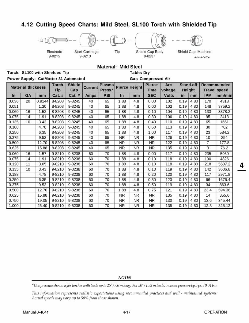
Manual 0-4641 4-17 OPERATION
4
4.12 Cutting Speed Charts: Mild Steel, SL100 Torch with Shielded Tip
NOTES
* Gas pressure shown is for torches with leads up to 25' / 7.6 m long. For 50' / 15.2 m leads, increase pressure by 5 psi / 0.34 bar.
This information represents realistic expectations using recommended practices and well - maintained systems.Actual speeds may vary up to 50% from those shown.
Electrode Start Cartridge Tip Shield Cup Body Shield Cap, Machine 9-8215 9-8213 9-8237 Art # A-04204
TorchTip
ShieldCap Current Plasma
Press.*Pierce Time
Arc voltage
In GA mm Cat. # Cat. # Amps PSI In mm SEC Volts in mm IPM mm/min0.036 20 0.9144 8-8208 9-8245 40 65 1.88 4.8 0.00 102 0.19 4.80 170 43180.051 1.30 8-8208 9-8245 40 65 1.88 4.8 0.00 103 0.19 4.80 148 3759.20.060 16 1.52 8-8208 9-8245 40 65 1.88 4.8 0.10 104 0.19 4.80 133 3378.20.075 14 1.91 8-8208 9-8245 40 65 1.88 4.8 0.30 106 0.19 4.80 95 24130.135 10 3.43 8-8208 9-8245 40 65 1.88 4.8 0.40 110 0.19 4.80 65 16510.188 4.78 8-8208 9-8245 40 65 1.88 4.8 0.60 113 0.19 4.80 30 7620.250 6.35 8-8208 9-8245 40 65 1.88 4.8 1.00 117 0.19 4.80 23 584.20.375 9.53 8-8208 9-8245 40 65 NR NR NR 126 0.19 4.80 10 2540.500 12.70 8-8208 9-8245 40 65 NR NR NR 122 0.19 4.80 7 177.80.625 15.88 8-8208 9-8245 40 65 NR NR NR 135 0.19 4.80 3 76.20.060 16 1.57 9-8210 9-8238 60 70 1.88 4.8 0.00 117 0.19 4.80 235 59690.075 14 1.91 9-8210 9-8238 60 70 1.88 4.8 0.10 118 0.19 4.80 190 48260.120 11 3.05 9-8210 9-8238 60 70 1.88 4.8 0.10 118 0.19 4.80 218 5537.20.135 10 3.43 9-8210 9-8238 60 70 1.88 4.8 0.10 119 0.19 4.80 142 3606.80.188 4.78 9-8210 9-8238 60 70 1.88 4.8 0.20 120 0.19 4.80 117 2971.80.250 6.35 9-8210 9-8238 60 70 1.88 4.8 0.30 123 0.19 4.80 66 1676.40.375 9.53 9-8210 9-8238 60 70 1.88 4.8 0.50 119 0.19 4.80 34 863.60.500 12.70 9-8210 9-8238 60 70 1.88 4.8 0.75 121 0.19 4.80 23.4 594.360.625 15.88 9-8210 9-8238 60 70 NR NR NR 135 0.19 4.80 14 355.60.750 19.05 9-8210 9-8238 60 70 NR NR NR 130 0.19 4.80 13.6 345.441.000 25.40 9-8210 9-8238 60 70 NR NR NR 135 0.19 4.80 12.8 325.12
Pierce Height RecommendedTravel speed
Stand-offHeightMaterial thickness
Gas: Compressed Air
Material: Mild SteelTorch: SL100 with Shielded TipPower Supply: CutMaster 81 Automated
Table: Dry
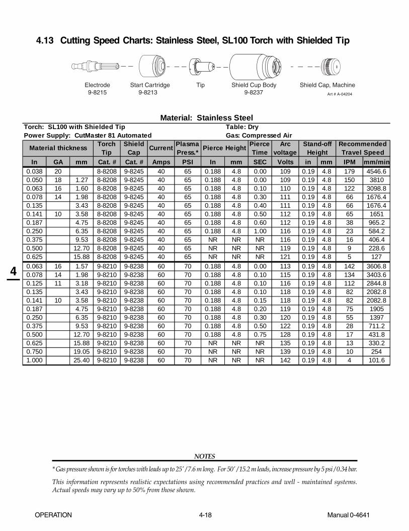
OPERATION 4-18 Manual 0-4641
4
4.13 Cutting Speed Charts: Stainless Steel, SL100 Torch with Shielded Tip
NOTES
* Gas pressure shown is for torches with leads up to 25' / 7.6 m long. For 50' / 15.2 m leads, increase pressure by 5 psi / 0.34 bar.
This information represents realistic expectations using recommended practices and well - maintained systems.Actual speeds may vary up to 50% from those shown.
Electrode Start Cartridge Tip Shield Cup Body Shield Cap, Machine 9-8215 9-8213 9-8237 Art # A-04204
TorchTip
ShieldCap Current Plasma
Press.*Pierce Time
Arc voltage
In GA mm Cat. # Cat. # Amps PSI In mm SEC Volts in mm IPM mm/min0.038 20 8-8208 9-8245 40 65 0.188 4.8 0.00 109 0.19 4.8 179 4546.60.050 18 1.27 8-8208 9-8245 40 65 0.188 4.8 0.00 109 0.19 4.8 150 38100.063 16 1.60 8-8208 9-8245 40 65 0.188 4.8 0.10 110 0.19 4.8 122 3098.80.078 14 1.98 8-8208 9-8245 40 65 0.188 4.8 0.30 111 0.19 4.8 66 1676.40.135 3.43 8-8208 9-8245 40 65 0.188 4.8 0.40 111 0.19 4.8 66 1676.40.141 10 3.58 8-8208 9-8245 40 65 0.188 4.8 0.50 112 0.19 4.8 65 16510.187 4.75 8-8208 9-8245 40 65 0.188 4.8 0.60 112 0.19 4.8 38 965.20.250 6.35 8-8208 9-8245 40 65 0.188 4.8 1.00 116 0.19 4.8 23 584.20.375 9.53 8-8208 9-8245 40 65 NR NR NR 116 0.19 4.8 16 406.40.500 12.70 8-8208 9-8245 40 65 NR NR NR 119 0.19 4.8 9 228.60.625 15.88 8-8208 9-8245 40 65 NR NR NR 121 0.19 4.8 5 1270.063 16 1.57 9-8210 9-8238 60 70 0.188 4.8 0.00 113 0.19 4.8 142 3606.80.078 14 1.98 9-8210 9-8238 60 70 0.188 4.8 0.10 115 0.19 4.8 134 3403.60.125 11 3.18 9-8210 9-8238 60 70 0.188 4.8 0.10 116 0.19 4.8 112 2844.80.135 3.43 9-8210 9-8238 60 70 0.188 4.8 0.10 118 0.19 4.8 82 2082.80.141 10 3.58 9-8210 9-8238 60 70 0.188 4.8 0.15 118 0.19 4.8 82 2082.80.187 4.75 9-8210 9-8238 60 70 0.188 4.8 0.20 119 0.19 4.8 75 19050.250 6.35 9-8210 9-8238 60 70 0.188 4.8 0.30 120 0.19 4.8 55 13970.375 9.53 9-8210 9-8238 60 70 0.188 4.8 0.50 122 0.19 4.8 28 711.20.500 12.70 9-8210 9-8238 60 70 0.188 4.8 0.75 128 0.19 4.8 17 431.80.625 15.88 9-8210 9-8238 60 70 NR NR NR 135 0.19 4.8 13 330.20.750 19.05 9-8210 9-8238 60 70 NR NR NR 139 0.19 4.8 10 2541.000 25.40 9-8210 9-8238 60 70 NR NR NR 142 0.19 4.8 4 101.6
Material: Stainless SteelTorch: SL100 with Shielded TipPower Supply: CutMaster 81 Automated
Table: DryGas: Compressed Air
RecommendedTravel Speed
Stand-offHeightPierce HeightMaterial thickness

Manual 0-4641 4-19 OPERATION
4
4.14 Cutting Speed Charts: Aluminum, SL100 Torch with Shielded Tip
NOTES
* Gas pressure shown is for torches with leads up to 25' / 7.6 m long. For 50' / 15.2 m leads, increase pressure by 5 psi / 0.34 bar.
This information represents realistic expectations using recommended practices and well - maintained systems.Actual speeds may vary up to 50% from those shown.
Electrode Start Cartridge Tip Shield Cup Body Shield Cap, Machine 9-8215 9-8213 9-8237 Art # A-04204
TorchTip
ShieldCap Current Plasma
Press.*Pierce Time
Arc voltage
In GA mm Cat. # Cat. # Amps PSI In mm SEC Volts in mm IPM mm/min0.04 20 1.02 8-8208 9-8245 40 65 0.188 4.8 0.00 100 0.19 4.8 220 5588
0.051 1.30 8-8208 9-8245 40 65 0.188 4.8 0.00 102 0.19 4.8 220 55880.064 16 1.63 8-8208 9-8245 40 65 0.188 4.8 0.10 104 0.19 4.8 220 55880.079 14 2.01 8-8208 9-8245 40 65 0.188 4.8 0.30 108 0.19 4.8 149 3784.60.125 3.18 8-8208 9-8245 40 65 0.188 4.8 0.35 112 0.19 4.8 73 1854.20.135 3.43 8-8208 9-8245 40 65 0.188 4.8 0.40 115 0.19 4.8 69 1752.60.187 4.75 8-8208 9-8245 40 65 0.188 4.8 0.60 118 0.19 4.8 50 12700.250 6.35 8-8208 9-8245 40 65 0.188 4.8 1.00 122 0.19 4.8 25 6350.375 9.53 8-8208 9-8245 40 65 NR NR NR 129 0.19 4.8 11 279.40.500 12.70 8-8208 9-8245 40 65 NR NR NR 134 0.19 4.8 7 177.80.625 15.88 8-8208 9-8245 40 65 NR NR NR 138 0.19 4.8 4 101.60.034 22 1.57 9-8210 9-8238 60 70 0.188 4.8 0.00 101 0.19 4.8 352 8940.80.064 16 1.63 9-8210 9-8238 60 70 0.188 4.8 0.10 105 0.19 4.8 352 8940.80.125 3.18 9-8210 9-8238 60 70 0.188 4.8 0.10 109 0.19 4.8 352 8940.80.135 3.43 9-8210 9-8238 60 70 0.188 4.8 0.10 112 0.19 4.8 272 6908.80.141 3.58 9-8210 9-8238 60 70 0.188 4.8 0.15 118 0.19 4.8 220 55880.187 4.75 9-8210 9-8238 60 70 0.188 4.8 0.20 122 0.19 4.8 136 3454.40.250 6.35 9-8210 9-8238 60 70 0.188 4.8 0.30 126 0.19 4.8 76 1930.40.375 9.53 9-8210 9-8238 60 70 0.188 4.8 0.50 129 0.19 4.8 46 1168.40.500 12.70 9-8210 9-8238 60 70 0.188 4.8 0.75 136 0.19 4.8 28 711.20.625 15.88 9-8210 9-8238 60 70 NR NR NR 139 0.19 4.8 19 482.60.750 19.05 9-8210 9-8238 60 70 NR NR NR 142 0.19 4.8 14 355.61.000 25.40 9-8210 9-8238 60 70 NR NR NR 150 0.19 4.8 4 101.6
Pierce Height RecommendedTravel Speed
Stand-offHeightMaterial thickness
Material: AluminumTorch: SL100 with Shielded TipPower Supply: CutMaster 81 Automated
Table: DryGas: Compressed Air

OPERATION 4-20 Manual 0-4641
4
Art # A-04381 Shield Cap, Machine
Electrode Start Cartridge Tip Shield Cup Body 9-8215 9-8213 9-8237
Shield Cap, Deflector9-8243
4.15 Operator's Custom Cutting Speed Charts
TorchTip
ShieldCap Current Plasma
Press.*Pierce Time
Arc voltage
In GA mm Cat. # Cat. # Amps PSI In mm SEC Volts in mm IPM mm/min
RecommendedTravel Speed
Stand-offHeightPierce HeightMaterial thickness
Material: Torch: SL100 with Shielded TipPower Supply: CutMaster 81 Automated
Table: DryGas: Compressed Air
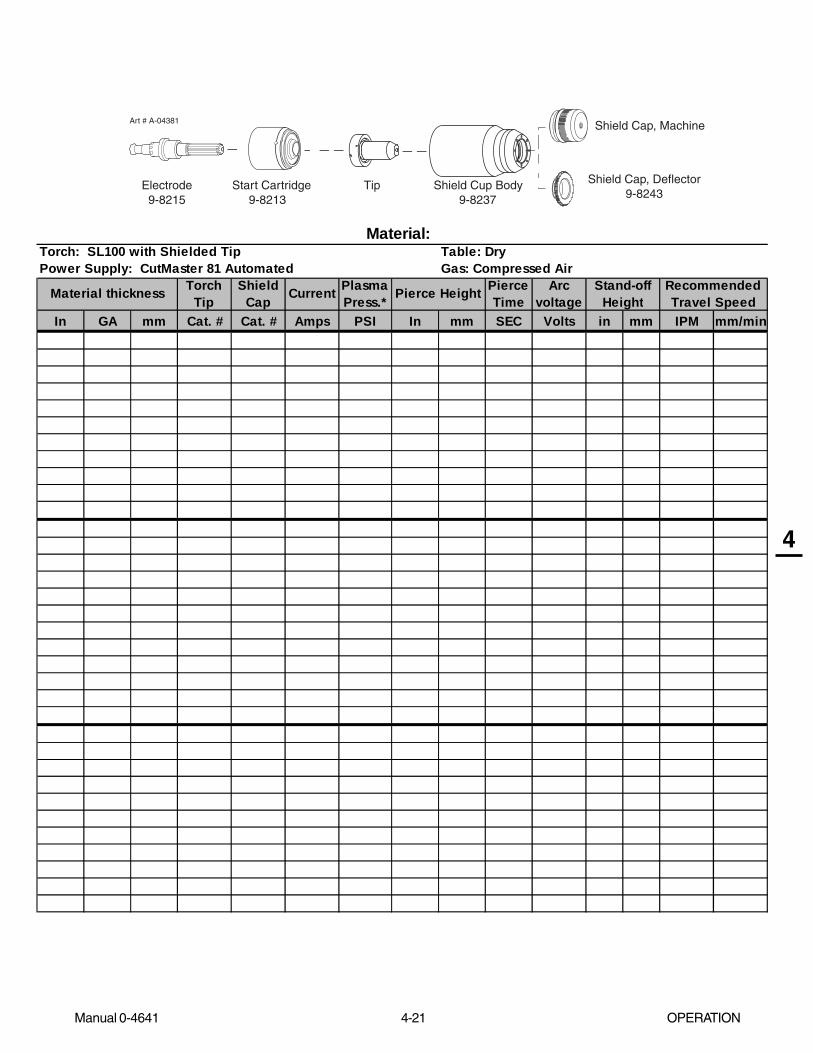
Manual 0-4641 4-21 OPERATION
4
Art # A-04381 Shield Cap, Machine
Electrode Start Cartridge Tip Shield Cup Body 9-8215 9-8213 9-8237
Shield Cap, Deflector9-8243
TorchTip
ShieldCap Current Plasma
Press.*Pierce Time
Arc voltage
In GA mm Cat. # Cat. # Amps PSI In mm SEC Volts in mm IPM mm/min
RecommendedTravel Speed
Stand-offHeightPierce HeightMaterial thickness
Material: Torch: SL100 with Shielded TipPower Supply: CutMaster 81 Automated
Table: DryGas: Compressed Air

OPERATION 4-22 Manual 0-4641
4
Art # A-04381 Shield Cap, Machine
Electrode Start Cartridge Tip Shield Cup Body 9-8215 9-8213 9-8237
Shield Cap, Deflector9-8243
TorchTip
ShieldCap Current Plasma
Press.*Pierce Time
Arc voltage
In GA mm Cat. # Cat. # Amps PSI In mm SEC Volts in mm IPM mm/min
RecommendedTravel Speed
Stand-offHeightPierce HeightMaterial thickness
Material: Torch: SL100 with Shielded TipPower Supply: CutMaster 81 Automated
Table: DryGas: Compressed Air
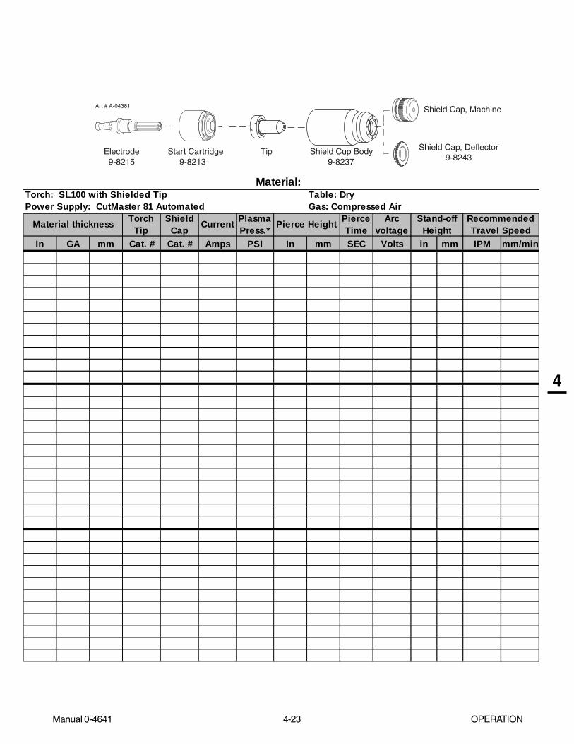
Manual 0-4641 4-23 OPERATION
4
Art # A-04381 Shield Cap, Machine
Electrode Start Cartridge Tip Shield Cup Body 9-8215 9-8213 9-8237
Shield Cap, Deflector9-8243
TorchTip
ShieldCap Current Plasma
Press.*Pierce Time
Arc voltage
In GA mm Cat. # Cat. # Amps PSI In mm SEC Volts in mm IPM mm/min
RecommendedTravel Speed
Stand-offHeightPierce HeightMaterial thickness
Material: Torch: SL100 with Shielded TipPower Supply: CutMaster 81 Automated
Table: DryGas: Compressed Air

OPERATION 4-24 Manual 0-4641
4
Art # A-04381 Shield Cap, Machine
Electrode Start Cartridge Tip Shield Cup Body 9-8215 9-8213 9-8237
Shield Cap, Deflector9-8243
TorchTip
ShieldCap Current Plasma
Press.*Pierce Time
Arc voltage
In GA mm Cat. # Cat. # Amps PSI In mm SEC Volts in mm IPM mm/min
RecommendedTravel Speed
Stand-offHeightPierce HeightMaterial thickness
Material: Torch: SL100 with Shielded TipPower Supply: CutMaster 81 Automated
Table: DryGas: Compressed Air

Manual 0-4641 5-1 SERVICE
5
SECTION 5:SERVICE
5.01 General Maintenance
A. Filter Element Replacement
The Regulator/Filter Assembly is on the rear panel. For better system performance, the Regulator/Filter Assembly filter elementshould be checked per the Maintenance Schedule (Appendix 3), and either cleaned or replaced.
1. Remove power from the power supply; turn off the gas supply and bleed down the system. Turn the regulator adjustmentknob to the 'zero' setting.
2. Unscrew the bowl on the bottom of the Regulator/Filter Assembly. The filter element will be visible and still attached tothe main body of the Regulator/Filter.
3. Grasp the filter element and unscrew it from the Regulator/Filter body. The filter element will come off with a spool andsome additional pieces.
4. Note the correct assembly of the filter/spool then remove the filter from the spool and either clean it or replace it.
5. The filter element and spool, with the baffle ring in place (teeth facing downward) can be screwed back into the Regulatorbody by compressing the spring on the spool. Tighten firmly by hand.
Art # A-02995
Regulator/FilterAssembly
Spool
Bowl
Spring
FilterElementNo. 9-4414
Baffle Ring
Regulator/Filter Element Replacement
6. Reinstall the bowl.
7. Turn on the air supply.

SERVICE 5-2 Manual 0-4641
5
B. Single-Stage Filter Element Replacement
These instructions apply to power supplies where the Single-Stage Filter has been installed.
The Power Supply shuts down automatically when the Filter Element becomes completely saturated. The Filter Element can beremoved from its housing, dried, and reused. Allow 24 hours for Element to dry.
1. Remove power from power supply.
2. Shut off air supply and bleed down system before disassembling Filter to change Filter Element.
3. Disconnect gas supply hose.
4. Turn the Cover counter-clockwise and remove it from the Filter Housing. The Filter Element is located inside theHousing.
Art # A-02476
FilterElement
(Cat. No. 9-7741)
Housing
Cover
BarbedFitting
Spring
Assembled FilterO-ring
(Cat. No. 9-7743)
Single-Stage Filter Element Replacement
5. Remove the Filter Element from the Housing and set Element aside to dry.
6. Wipe inside of housing clean, then insert the replacement Filter Element open side first.
7. Replace Housing on Cover.
8. Reattach gas supply.
NOTE
If unit leaks between housing and cover, inspect the "O" Ring for cuts or other damage.
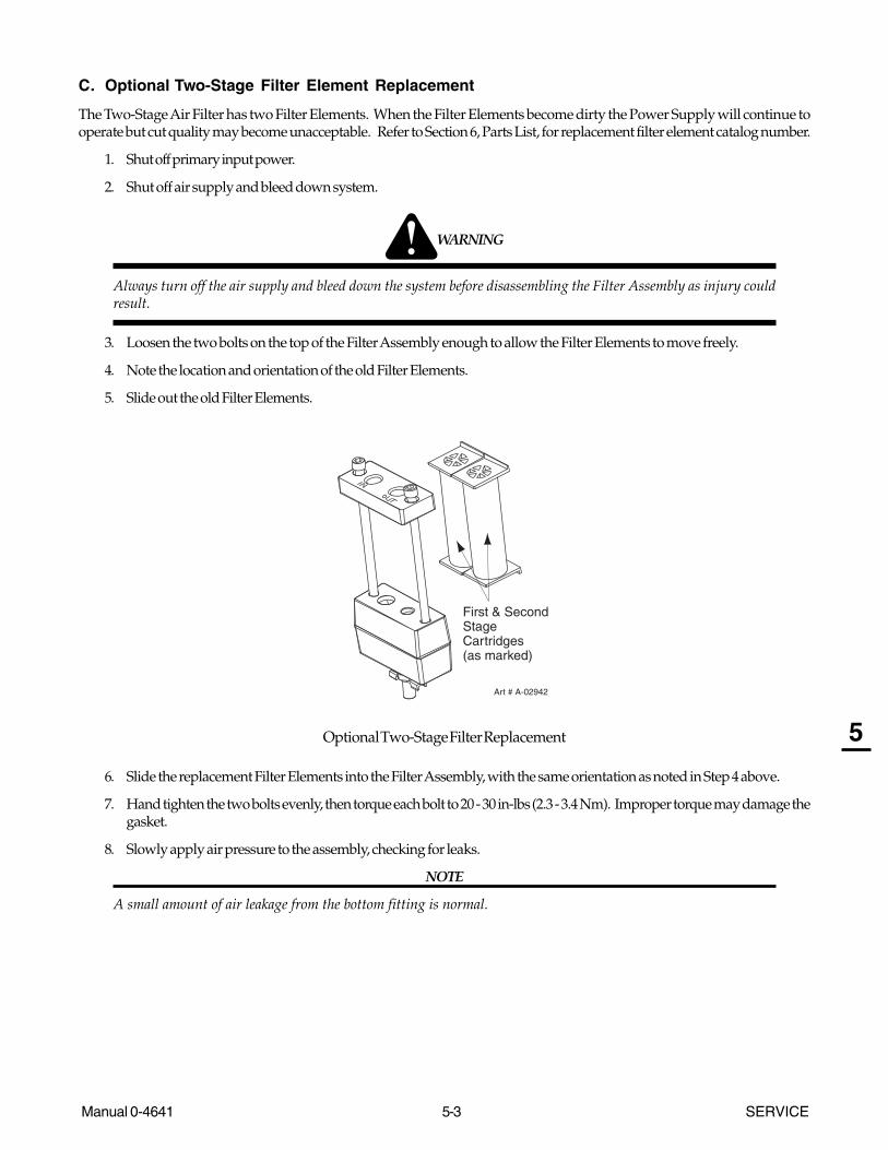
Manual 0-4641 5-3 SERVICE
5
C. Optional Two-Stage Filter Element Replacement
The Two-Stage Air Filter has two Filter Elements. When the Filter Elements become dirty the Power Supply will continue tooperate but cut quality may become unacceptable. Refer to Section 6, Parts List, for replacement filter element catalog number.
1. Shut off primary input power.
2. Shut off air supply and bleed down system.
WARNING
Always turn off the air supply and bleed down the system before disassembling the Filter Assembly as injury couldresult.
3. Loosen the two bolts on the top of the Filter Assembly enough to allow the Filter Elements to move freely.
4. Note the location and orientation of the old Filter Elements.
5. Slide out the old Filter Elements.
First & Second StageCartridges (as marked)
Art # A-02942
Optional Two-Stage Filter Replacement
6. Slide the replacement Filter Elements into the Filter Assembly, with the same orientation as noted in Step 4 above.
7. Hand tighten the two bolts evenly, then torque each bolt to 20 - 30 in-lbs (2.3 - 3.4 Nm). Improper torque may damage thegasket.
8. Slowly apply air pressure to the assembly, checking for leaks.
NOTE
A small amount of air leakage from the bottom fitting is normal.
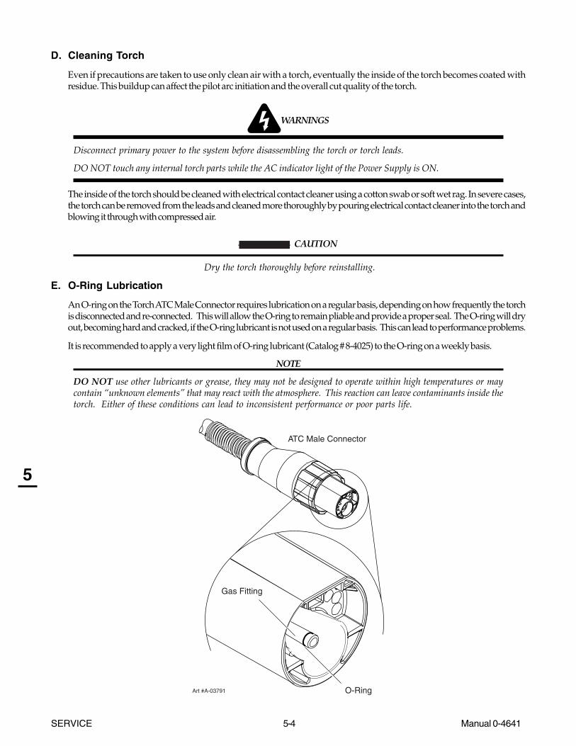
SERVICE 5-4 Manual 0-4641
5
D. Cleaning Torch
Even if precautions are taken to use only clean air with a torch, eventually the inside of the torch becomes coated withresidue. This buildup can affect the pilot arc initiation and the overall cut quality of the torch.
WARNINGS
Disconnect primary power to the system before disassembling the torch or torch leads.
DO NOT touch any internal torch parts while the AC indicator light of the Power Supply is ON.
The inside of the torch should be cleaned with electrical contact cleaner using a cotton swab or soft wet rag. In severe cases,the torch can be removed from the leads and cleaned more thoroughly by pouring electrical contact cleaner into the torch andblowing it through with compressed air.
CAUTION
Dry the torch thoroughly before reinstalling.
E. O-Ring Lubrication
An O-ring on the Torch ATC Male Connector requires lubrication on a regular basis, depending on how frequently the torchis disconnected and re-connected. This will allow the O-ring to remain pliable and provide a proper seal. The O-ring will dryout, becoming hard and cracked, if the O-ring lubricant is not used on a regular basis. This can lead to performance problems.
It is recommended to apply a very light film of O-ring lubricant (Catalog # 8-4025) to the O-ring on a weekly basis.
NOTE
DO NOT use other lubricants or grease, they may not be designed to operate within high temperatures or maycontain “unknown elements” that may react with the atmosphere. This reaction can leave contaminants inside thetorch. Either of these conditions can lead to inconsistent performance or poor parts life.
ATC Male Connector
Art #A-03791
Gas Fitting
O-Ring

Manual 0-4641 5-5 SERVICE
5
5.02 Common Faults
1. Insufficient Penetration
a. Cutting speed too fast
b. Torch tilted too much
c. Metal too thick
d. Worn torch parts
e. Cutting current too low
f. Non - Genuine Thermal Dynamics parts used
g. Incorrect gas pressure
2. Main Arc Extinguishes
a. Cutting speed too slow
b. Torch standoff too high from workpiece
c. Cutting current too high
d. Work cable disconnected
e. Worn torch parts
f. Non - Genuine Thermal Dynamics parts used
3. Excessive Dross Formation
a. Cutting speed too slow
b. Torch standoff too high from workpiece
c. Worn torch parts
d. Improper cutting current
e. Non - Genuine Thermal Dynamics parts used
f. Incorrect gas pressure
4. Short Torch Parts Life
a. Oil or moisture in air source
b. Exceeding system capability (material too thick)
c. Excessive pilot arc time
d. Gas pressure too low
e. Improperly assembled torch
f. Non - Genuine Thermal Dynamics parts used
5. Difficult Piloting
a. Worn torch parts
b. Non - Genuine Thermal Dynamics parts used
c. Incorrect gas pressure

SERVICE 5-6 Manual 0-4641
5
5.03 Basic Troubleshooting
WARNING
There are extremely dangerous voltage and power levels present inside this unit. Do not attempt to diagnose orrepair unless you have had training in power electronics measurement and troubleshooting techniques.
A. Basic Troubleshooting: Overview
This guide covers basic troubleshooting. It is helpful for solving many of the common problems that can arise with this system.
Follow all instructions as listed and complete each section in the order presented.
B. How to Use This Guide
The following information will help the Operator determine the most likely causes for various symptoms. Follow all instructionsas listed and complete each section in the order presented.
This guide is set up in the following manner:
X. Symptom (Bold Type)
Any Special Instructions
1. Cause
a. Check / Remedy
Locate your symptom, check the causes (easiest listed first), then remedies. Repair as needed being sure to verify that unitoperates properly after any repairs.
C. Common Symptoms
A. AC indicator OFF
1. Switch at main power panel in OFF (open) position.
a. Close main power switch.
2. Power Supply ON / OFF switch in OFF (down) position.
a. Turn switch to ON (up).
3. Torch is not connected properly to Power Supply
a. Turn power supply ON / OFF switch to OFF (down). Check torch connection to Power Supply. Tighten or adjust asrequired. Do not use tools. Turn power supply ON / OFF switch to ON (up).
4. Shield cup not fully tightened on torch head
a. Check shield cup for proper installation. Do not overtighten. Do not use tools to tighten.
CAUTION
When the shield cup is properly installed, there is a slight gap between the shield cup and the torch head. Gas ventsthrough this gap as part of normal operation. Do not attempt to force the shield cup to close this gap. Forcing theshield cup against the torch head can damage components.
5. Main power line fuse(s) or circuit breaker(s) blown
a. Check main power panel fuse(s). Replace as required.

Manual 0-4641 5-7 SERVICE
5
6. Unit internal fuse blown or loose
a. If blown, double-check input voltage and replace fuse per Section 5.09-C.
7. Actual input voltage does not correspond to voltage of unit
a. Verify that the input line voltage is correct. Refer to Section 2, Input Wiring Requirements.
B. Gas flows continuously when power is turned on, AC indicator flashes
1. Torch switch is activated (closed) before user turns power on.
a. Release torch switch.
2. Faulty torch switch in CNC Control.
a. Check torch switch for continuity. Replace if necessary.
C. Gas flows continuously; Torch will not pilot when torch switch is activated; AC indicator ON
1. System is in SET mode
a. Change RUN / Rapid Auto Restart / SET switch to RUN (up).
D. No gas flow; RUN / Rapid Auto Restart / SET switch in SET position; Fans operate; AC indicator ON; GAS
indicator OFF
1. Gas not connected
a. Check gas connections.
2. Gas pressure too low for power supply operation
a. Adjust pressure to 70-75 psi / 4.8 - 5.2 bar.
E. Torch will not pilot; gas flows; AC indicator ON, GAS , TEMP , and DC indicators OFF
1. Gas pressure is below power supply minimum requirement.
a. Adjust pressure to 70-75 psi / 4.8 - 5.2 bar.
NOTE
Minimum pressure for power supply operation is lower than minimum for torch operation.
F. Torch will not pilot; gas flows; AC and Gas indicators ON; DC and TEMP indicators OFF
1. Gas pressure is below torch minimum requirement (Minimum pressure for power supply operation is lower thanminimum required for torch operation.)
a. Adjust pressure to 70-75 psi / 4.8 - 5.2 bar.
2. Positive and negative wire connections to automation interface PC Board terminals J2-1 and J2-3 are reversed.
a. Check wire connections, correct if necessary.
NOTE
This condition applies to CNC Controllers (other than the SC-11) with semiconductor switches.

SERVICE 5-8 Manual 0-4641
5
G. Torch will not pilot; no gas flow; AC indicator ON, GAS indicator ON, DC indicator ON
1. Start cartridge missing from torch
a. Shut off power supply. Remove shield cup, install start cartridge. Reinstall torch tip and shield cup. Turn powersupply ON / OFF switch to ON (up).
2. Shield cup is loose on torch
a. Check shield cup; tighten if necessary.
NOTE
When operating the torch in a normal condition, a small amount of gas vents through the gap between the shield cupand torch head. Do not attempt to over tighten the shield cup as irreparable damage to internal components may result.
3. Upper O-ring on torch head is in wrong position.
a. Remove shield cup from torch; check position of upper O-ring. Correct if necessary.
Upper Groovewith Vent HolesMust Remain Open
Threads
Upper O-Ringin Correct Groove
Lower O-Ring Art # A-03725
H. Torch will not pilot; AC , GAS , and TEMP indicators ON, DC indicator OFF
1. Air flow blocked
a. Check for blocked air flow around the unit and correct condition.
2. Unit is overheated
a. Let unit cool down for at least 5 minutes. Make sure the unit has not been operated beyond Duty Cycle limit. Referto duty cycle data in Section 2.
3. Input line voltage is low
a. Check and connect to proper input power line.

Manual 0-4641 5-9 SERVICE
5
I. Torch cannot be activated; AC indicator flashing; Gas indicator ON; Temp indicator OFF; DC
indicator OFF
1. System is in protective interlock mode. (Torch switch in CNC Controller in ON position while turning on power supplyON / OFF switch.)
a. Release torch switch.
2. System is in protective interlock mode. (Torch parts are missing, defective, or loose.)
a. Release torch switch, and set power supply ON / OFF switch to OFF (down). Open main disconnect switch.Check torch parts. Replace parts as needed. Reinstall shield cup; hand - tighten it securely against the torchhead. Do not overtighten. Do not use tools. Close main disconnect switch. Set ON / OFF switch to ON (up)position.
J . Gas cycles on and off without torch switch being activated; AC indicator Flashing; Gas indicator ON; DC
indicator OFF
1. Torch tip or electrode missing
a. Shut off power supply. Remove shield cup, install missing part(s). Turn power supply ON / OFF switch to ON (up).
2. Start cartridge stuck or worn.
a. Remove the start cartridge. Check for excessive wear, plugged gas holes, or discoloration. Check the lower end fittingfor free motion. Replace if necessary.
Art # A-07168
Spring-Loaded Cylinder at Full Compression
Spring-Loaded Cylinder at Full Extension
1/8” (3 mm)
K. No cutting output; Torch pilots; Gas flows; Fans operate; AC , Gas , and DC indicator ON;
TEMP indicator OFF
1. Work cable not connected to work piece, or connection is poor
a. Make sure that work cable has a proper connection to a clean, dry area of the workpiece or the cutting table.
2. Faulty Torch
a. Return for repair or have qualified technician repair.

SERVICE 5-10 Manual 0-4641
5
L. Torch cuts but not adequately
1. Incorrect setting of output current (A) control
a. Check and adjust to proper setting.
2. Torch consumables worn
a. Check torch consumables; replace as needed.
3. Work cable connection is poor
a. Make sure that work cable has a proper connection to a clean, dry area of the workpiece or cutting table.
4. Torch is being moved too fast across workpiece
a. Reduce cutting speed.
5. Excessive oil or moisture in torch
a. Put RUN / RAPID AUTO RESTART / SET switch in SET (down) position. Hold torch 1/8 inch (3 mm) fromclean surface while purging and observe oil or moisture buildup (do not activate torch). If there are contami-nants in the gas, additional filtering may be needed.
6. Fluctuations in input power
a. Have electrician check input line voltage.
M. Arc shuts off during operation; arc will not restart when torch switch is activated.
1. Power Supply is overheated (TEMP indicator ON)
a. Let unit cool down for at least 5 minutes. Make sure the unit has not been operated beyond Duty Cycle limit. Referto Section 2 for duty cycle specifications.
2. Fan blades blocked (TEMP indicator ON)
a. Check and clear blades.
3. Air flow obstructed (TEMP indicator ON)
a. Check for obstructed air flow around the unit and correct condition.
4. Gas pressure too low (GAS indicator OFF when torch switch is activated)
a. Check source for at least 60 psi / 4.1 bar; adjust as needed. (Minimum pressure for power supply operation is lowerthan minimum required for torch operation.)
5. Torch consumables worn
a. Check torch consumables; replace as needed.
N. AC indicator remains ON when shield cup is removed
1. Faulty PIP switch in torch
a. Check PIP switch for continuity; replace if necessary
Manual 0-4641 5-11 SERVICE
5
5.04 Advanced Troubleshooting Guide - General Information
WARNING
There are extremely dangerous voltage and power levels present inside this unit. Do not attempt to diagnose orrepair unless you have had training in power electronics measurement and troubleshooting techniques.
A. General Information
This Section covers advanced troubleshooting, which requires power supply disassembly and live measurements. Advancedtroubleshooting and repair of this unit is a process which should be undertaken only by those familiar with high voltage highpower electronic equipment.
If major complex subassemblies are faulty, the faulty subassembly must be returned for repair. Refer to Repairs & ReplacementProcedures, for parts replacement instructions. Replacement instructions for some parts are included in this manual. Replace-ment instructions for parts not covered in this manual are included with the replacement part.
Under no circumstances are field repairs to be attempted on Printed Circuit Boards or other subassemblies of this unit. Evidenceof unauthorized repairs will void the factory warranty.
NOTE
Follow all instructions as listed and complete each in the order presented.
B. How to Use the Troubleshooting Guide
The following information is a guide to help the Service Technician determine the most likely causes for various symptoms. Thisguide is set up in the following manner:
1. Perform operational check(s) on the equipment to isolate problem to possible circuit(s) per Subsection 5.06, Circuit FaultIsolation.
2. Determine symptom and isolate to defective assembly using the following format:
X. Symptom (Bold Type)
Any Special Instructions (Text Type)
1. Cause (Italic Type)
a. Check/Remedy (Text Type)
3. Locate your symptom in the appropriate Subsection.
4. Check the causes (easiest listed first) for the symptom.
5. Check the remedies listed for each cause.
6. Repair as needed being sure to verify that unit is fully operational after any repairs.
NOTES
Many signals are transferred between Printed Circuit Board Assemblies on Cables. If these cables become faultythey can then cause various problems. Do not forget about these cables when troubleshooting.
While troubleshooting visually inspect the internal components for signs of overheating, fractures and damage.

SERVICE 5-12 Manual 0-4641
5
C. Main Input and Internal Power Tests
1. Connect main AC power to the unit.
2. Set the Power Supply ON/OFF switch to ON (up) and note the following:
• AC indicator steady ON
• Gas solenoid energizes (clicks)
• Main PCB Relay energizes, pulling in main input contactor (W1)
• TEMP Indicator OFF
• GAS Indicator ON if input pressure is sufficient for power supply operation. Minimum pressure for power supply
operation is lower than minimum for torch operation.
• Gas flows
• Fans operate
• DC indicator is OFF3. Set the Power Supply RUN / RAPID AUTO RESTART / SET switch to the RUN (up) position and note the following:
• Gas flow stopsThis completes the Main Input and Internal Power Tests. If the above are all correct then proceed to paragraph ‘D’. If not, notethe symptom and proceed to Subsection 5.05, Main Input and Internal Power Problems.
D. Pilot Arc Test
1. Activate the torch to establish a pilot arc and note the following:
• Gas flows
• Preflow delay (two seconds) then DC indicator turns ON
• Pilot arc is establishedThis completes the Pilot Arc Test. If the above are all correct then proceed to paragraph ‘E’. If the unit does not function properly,then note the symptom and proceed to Subsection 5.06, Pilot Arc Problems.
E. Main Arc Test
Make sure the work cable is firmly connected to the workpiece. Activate the torch to establish a pilot arc.
Bring the torch to within 1/8"-3/8" (3-10 mm) of the workpiece to establish the main cutting arc, and note the following:
• Main cutting arc startsThis completes the Main Arc Test. If the above are all correct then the equipment should be operating properly. If problems stillpersist then contact Technical Services.
If the torch does not function as noted then note the symptom and proceed to Subsection 5.07, Main Arc Problems.

Manual 0-4641 5-13 SERVICE
5
5.05 Main Input and Internal Power Problems
A. Opening Power Supply Enclosure
The cover of the Power Supply must be removed for access to input power connections and test points.
WARNING
Disconnect primary power at the source before assembling or disassembling the Power Supply, torch parts, or torchand leads assemblies.
1. Remove the upper screws securing the cover to the main assembly.2. Loosen, but do not remove, the lower screws.
NOTE
There is a ground wire attached from the cover to the main body of the unit.
3. Carefully lift the cover off the unit, and remove the nut securing the ground wire to the side panel.
4. Re-install the cover by reversing the above steps.
Art # A-04510
Lowerscrews
Upper screws
Ground wire
Lowerscrews
Cover Removal

SERVICE 5-14 Manual 0-4641
5
Locate your symptom below:
A. Main power line fuses blow as soon as main disconnect is closed
1. Input power cable installed incorrectly or defective power cord.
a. Refer to Subsection 5.07 and check that the input power cable is not defective or installed incorrectly.
2. Main input contactor (W1) stuck.
a. Check contactor. Replace if stuck.
B. Main power line fuses blow immediately after the ON/OFF Switch is turned on.
1. Faulty Input Diode
a. Test Input Diode per Subsection 5.08-C; repair as necessary.
C. Fans do not operate; AC indicator OFF
1. Front Panel ON/OFF switch in OFF position
a. Place switch to ON (up) position.
2. Main power disconnect open
a. Close main power disconnect.
3. Torch is not properly connected to Power Supply.
a. Check torch connections to Power Supply. Tighten or adjust as needed.
4. Shield cup not fully tightened on torch head.
a. Check shield cup for proper installation. Do not overtighten.
5. Main power line fuses blown
a. Replace main power line fuses.
Art # A-03658
INPUTDIODE
TP1TP4 J24-3 J32J29
J18-5J23-1
J33
J27
J43
J34
J11
J15
FUSEJ23-3
J18-6
J15-1
J15-6
J15-5
J15-2
J24-1
Main Printed Circuit Board Layout (logic board not shown)

Manual 0-4641 5-15 SERVICE
5
6. Improper input power cable connections inside Power Supply
a. Refer to System Schematic and correct if needed.
7. Defective input power cable
a. Replace input power cable. Refer to subsection 5.09-L.
8. Fuse blown inside Power Supply
a. Replace internal Fuse per Subsection 5.09-C.
9. Line voltage above 10% tolerance (over voltage protection)
a. Reduce line supply.
10. Faulty Auxiliary Transformer (refer to Appendix pages, 28 VAC Circuit Diagram)
Measure for 28 VAC on Main PC Board from J23-1 to J23-3.
a. If voltage is not present, replace the Main PC Board.
11. Faulty ON/OFF switch
Measure for 28 VAC on the Main PC Board between J18-5 to J18-6.
a. If voltage is not present replace the ON/OFF Switch.
12. Faulty Main PC Board
Measure for 12 vdc on Main PC Board from TP4 to TP1.
a. If voltage is not present, replace the Main PC Board.
D. AC and TEMP indicators ON, fans do not run
1. Air flow through unit is restricted
a. Provide adequate air flow
2. Exceeded Duty Cycle of Power Supply
a. Deactivate torch and wait for fan to cool unit. Refer to Specifications Section for proper duty Cycle for this unit.
3. Faulty Fan(s)
Measure for 230 VAC (±) on the Main PC Board from J15-1 to J15-2, and from J15-5 to J15-6.
• If voltage at J15-1 to J15-2 is correct, replace lower Fan (M1).
• If voltage at J15-5 to J15-6 is correct, replace upper Fan (M2).
4. Faulty Temperature Sensor / Switch
a. Check IGBT Heatsink Temp Sensor (TS1). Disconnect wire connector P29 from terminal J29 on Main PCBoard. Check connector pins 1 and 2 for 10K ohm (±25%) (at ambient temperature). If resistance is not 10Kohm (±25%), replace TS1.
b. Check Inductor Temp Switch (TS2). Disconnect wire connector P32 from terminal J32 on Main PC Board.Check connector pins 1 and 2 for at least 12K ohms. If resistance is less than 12K ohms, replace outputinductor (L1). If temp switch is open, replace Main PC Board.

SERVICE 5-16 Manual 0-4641
5
E. No gas flow; AC indicator ON; TEMP , GAS and DC indicators OFF
1. RUN / RAPID AUTO RESTART / SET switch in RUN position
a. Change switch to SET position.
2. Gas supply not connected to unit
a. Connect to gas supply.
3. Gas supply not turned on
a. Turn gas supply on.
4. Faulty RUN / RAPID AUTO RESTART / SET switch
a. Check continuity.
5. Faulty Gas Solenoid circuit
a. Test Gas Solenoid circuit per Subsection 5.08-E; repair as necessary.
6. Faulty Logic Board
a. Replace logic board.
F. Gas flows; AC indicator ON; GAS and DC indicator OFF
1. Gas pressure too low
a. Set operating pressure per pressure setting label on power supply.
NOTE
Minimum pressure for power supply operation is lower than minimum required for torch operation.
2. Faulty Pressure Switch
Measure for 12 vdc from wire #10 to wire #11 at the Gas Pressure Switch, located on the right side of the unit. Refer toSystem Schematic in the Appendix pages.
a. If 12 vdc is present and pressure is above 50 psi (3.4 bar), replace Gas Pressure Switch/Solenoid Assembly. Refer toSection 5.08-A.
b. If pressure is above 50 psi (3.4 bar) and 12 vdc is not present, replace the Logic PC Board.
3. Faulty Wiring or Faulty Logic PC Board
Check for 12 vdc at Main PC Board pin J24-3 to J24-4 from the Logic PC Board. Refer to Appendix Pages, Main PC BoardLayout.
• If less than a volt, replace Logic PC Board.
G. Gas continues to flow with RUN / RAPID AUTO RESTART / SET switch in RUN position.
1. Damaged gas solenoid.
a. Turn the front panel ON/OFF switch to OFF.
• If gas continues to flow, debris from the air line is preventing the solenoid from closing. Clean or replace the solenoid.
2. Faulty RUN / RAPID AUTO RESTART / SET switch.
a. Remove one wire from the pressure switch. Check for ± 0 vdc at Main PC Board pin J24-3 to J24-4 from theLogic PC Board. Refer to Main PC Board Layout.
• If less than a volt, replace Logic PC Board.

Manual 0-4641 5-17 SERVICE
5
3. Faulty Logic PCB.
a. Measure for approximately 12 vdc between P1-7 and TP-1 on the Logic PCB.
• If 12 vdc is present, replace Logic PCB.
• If less than 2 vdc, replace Main PCB.
TP9
TP10
TP11
TP3
TP7TP8TP5
TP1
TP2
TP4
D13 TP6
Art # A-03654D25
D33
P1-7
P1-9
Logic Board Layout

SERVICE 5-18 Manual 0-4641
5
H. Gas flows continuously when power is turned on; AC indicator flashes
1. Torch switch is activated (closed) before user turns power on
a. Release torch switch.
2. Faulty torch switch
a. Check torch switch for continuity.
I. Gas cycles on and off when power is turned on; AC indicator flashes
1. Shield cup is loose.
a. Tighten shield cup by hand. Do not overtighten.
2. Torch tip, electrode, or start cartridge missing
a. Turn off power supply. Remove shield cup, install missing parts.
3. Start cartridge is stuck
a. Turn off power supply. Remove shield cup, tip, and start cartridge. Check lower end fitting on start cartridgefor free movement. Replace cartridge if lower end fitting does not move freely.
Art # A-07168
Spring-Loaded Cylinder at Full Compression
Spring-Loaded Cylinder at Full Extension
1/8” (3 mm)

Manual 0-4641 5-19 SERVICE
5
5.06 Pilot Arc Problems
WARNING
The following tests must be performed with the power supply connected to primary input power. There are extremelydangerous voltage and power levels present inside this unit. Do not attempt to diagnose or repair without propertraining in power electronics measurement and troubleshooting techniques.
Locate your symptom below:
A. Torch will not pilot; gas flows; AC indicator ON, GAS , TEMP , and DC indicators OFF
1. Gas pressure is below power supply minimum requirement. (Minimum pressure for power supply operation is lowerthan minimum required for torch operation.)
a. Adjust gas pressure per pressure setting label on power supply.
B. Torch will not pilot; gas flows; AC and Gas indicators ON; TEMP and DC indicators OFF
1. Gas pressure is below torch minimum requirement (Minimum pressure for power supply operation is lower thanminimum required for torch operation.)
a. Adjust gas pressure per pressure setting label on power supply.
2. Power Supply RUN / SET switch in SET position
a. Place RUN / SET switch to RUN position.
3. Upper O-ring on torch head is in wrong position.
a. Remove shield cup from torch; check position of upper O-ring. Correct if necessary.
Upper Groovewith Vent HolesMust Remain Open
Threads
Upper O-Ringin Correct Groove
Lower O-Ring Art # A-03725

SERVICE 5-20 Manual 0-4641
5
C. Torch will not pilot; AC , GAS , and TEMP indicators ON
1. Air flow blocked
a. Check for blocked air flow around the unit and correct condition.
2. Unit is overheated
a. Let unit cool down for at least 5 minutes. Make sure the unit has not been operated beyond Duty Cycle limit. Referto duty cycle data in Specifications Section.
3. Input line voltage is low
a. Check and connect to proper input power line.
4. Faulty Temperature Sensor / Switch
a. Refer to Appendix 15, Main PC Board Layout. Check IGBT Heatsink Temp Sensor (TS1). Disconnect wire connectorP29 from terminal J29 on Main PC Board. Check connector pins 1 and 2 for 10K ohm (±25%) (at ambient temperature).If resistance is not 10K ohm (±25%), replace TS1.
b. Check Inductor Temp Switch (TS2). Disconnect wire connector P32 from terminal J32 on Main PC Board. Checkconnector pins 1 and 2 for at least 12K ohms. If resistance is less than 12K ohms, replace output inductor (L1). If tempswitch is open, replace Main PC Board.
5. Faulty Logic PC Board
a. Check for (±) 12vdc on Main PC Board between J43-9 and TP1. If (±) 12vdc is present, replace Logic PC Board.
6. Faulty Main PC Board
a. Check for (±) 0 vdc on Main PC Board between J43-9 and TP1. If (±) 0 vdc is present, replace Main PC Board.
7. Faulty Fan(s)
Measure for (±) 230 VAC on the Main PC Board from J15-1 to J15-5, and from J15-2 to J15-6.
• If voltage at J15-1 to J15-5 is correct, replace upper Fan (M1).
• If voltage at J15-2 to J15-6 is correct, replace lower Fan (M2).

Manual 0-4641 5-21 SERVICE
5
D. Torch will not pilot when torch switch is activated; AC and GAS indicators ON; Temp and DC
indicators OFF
1. Gas pressure too high or too low
a. Adjust gas pressure per pressure setting label on power supply.
2. Torch tip, start cartridge, or electrode missing.
a. Turn off power supply. Remove shield cup, install missing parts.
3. Start cartridge is stuck
a. Turn off power supply. Remove shield cup, tip, and start cartridge. Check lower end fitting on start cartridgefor free movement. Replace cartridge if lower end fitting does not move freely.
Art # A-07168
Spring-Loaded Cylinder at Full Compression
Spring-Loaded Cylinder at Full Extension
1/8” (3 mm)
4. Worn or faulty torch parts
a. Inspect torch consumable parts. Replace if necessary.
E. Gas flows; AC indicator and GAS indicators ON; TEMP indicator off; ON; DC indicator
off or blinks on/off once.
1. Faulty IGBT or Output Diode Module Assembly(s)
a. Check per Subsection 5.08-C; repair as needed.
2. Faulty Main PCB
a. Test; repair as needed.

SERVICE 5-22 Manual 0-4641
5
F. Gas flows; No arc in torch; AC , GAS , and DC indicators ON; TEMP indicator off
1. Faulty IGBT(s)
a. Measure between the following points on the IGBTs:
• IGBT A: E4 to E10
E10 to E20
• IGBT B: E23 to E27
E27 to E30
Voltage should be approximately 20 vdc before the start signal is active. If voltage measures greater than 100vdc when the start signal is active, replace the respective IGBT(s).
Art # A-03659
INPUTDIODEE3
E7
E15
E10
E20
E4 J30E33
E26
E27
E30
J31 E23
J25
IGBT A IGBT B
J11
Main PC Board Layout (IGBT Test Points)

Manual 0-4641 5-23 SERVICE
5
G. No arc or intermittent arc in torch; Gas flows; AC , GAS , and DC indicators ON; TEMP indica-
tor off
1. Gas pressure set incorrectly (too high)
a. Reset gas pressure per pressure setting label on power supply.
2. Oil/moisture in air lines
a. Purge system. If problem corrected, add filters in line with air source.
3. Incorrect torch parts
a. Inspect the torch parts; replace as needed.
4. Faulty leads
a. Check torch leads continuity.
5. Faulty torch
a. Check torch.
6. Faulty connection of wire #58 or 62 to Pilot Board
a. Check wiring connection. Refer to the System Schematic in the Appendix. Connections should be:
• Wire #58 to Pilot Board terminal E58
• Wire #62 to Pilot Board terminal E62
If wires 58 and 62 are not connected to the proper terminals, replace the Pilot Board.
7. Faulty Main PC Board
a. Check for approximately 12 vdc at TP4 to TP1. If less than 2 vdc, replace the Main PC Board.
8. Faulty Logic Board or Faulty Pilot Board
a. Install a jumper between wires 58 and 62 on Pilot Board and retry piloting. If torch pilots with jumper installed, replacePilot Board. If torch does not pilot, replace Logic Board.

SERVICE 5-24 Manual 0-4641
5
5.07 Main Arc Problems
Locate your symptom below:
A. Main cutting arc will not start
1. Work cable not connected.
a. Connect work cable.
B. No cutting output
1. Torch not properly connected to power supply
a. Check that torch leads are properly attached to power supply
2. Shield cup not properly installed on torch
a. Check that shield cup is fully seated against torch head (do not overtighten)
3. Parts - In - Place (PIP) not satisfied.
a. Check that shield cup is properly installed.
b. Check switch in machine torch head - for continuity.
4. Faulty components in torch and leads assembly
a. Inspect torch assemblies and replace if necessary.
C. Limited output with no control
1. Poor input or output connections to power supply
a. Check all input and output connections.
2. Faulty components in torch and leads assembly
a. Inspect torch assemblies and replace if necessary.
D. Erratic or improper cutting output
1. Poor input or output connections to power supply
a. Check all input and output connections.
2. Current set too low at power supply
a. Increase current setting.
3. Torch is being moved too fast across workpiece
a. Reduce cutting speed.
4. Holding too high of a standoff.
a. Refer to recommended standoff heights provided in speed charts in Section 3. Adjust as needed.
5. Workpiece is painted or rusty.
a. Clean workpiece.

Manual 0-4641 5-25 SERVICE
5
6. Faulty Main PC Board or Logic Board.
a. Measure for ±0 vdc at TP2 to TP1 on the Logic Board when attempting to transfer. Refer to Logic Board Layout.
• If TP2 goes to 0 vdc replace Output Board.
• If not, replace Main PC Board.
7. Faulty Main Input Contactor.
a. Check per Subsection 5.14-D.
B. When operating the amperage drops off after the main cutting arc starts.
1. Torch tip contacts workpiece
Raise the torch tip off the work. At output settings over 40 amps, circuitry in the power supply automatically reducesoutput current to 40 amps if the torch tip contacts the workpiece.
2. Faulty Pilot Board
a. With power off and wires E58 and E62 disconnected from the pilot board, measure for continuity between terminals#E58 and #E62. If continuity is found, replace Pilot Board.
5.08 Test Procedures
The test procedures in this subsection are referenced in the troubleshooting section.
A. Safety Precautions
1. Significant DC Voltage exists after removal of input power. Allow two minutes for discharge time. Voltage measured on inputcapacitors must be zero before performing service on the power supply.
2. Do Not touch electrical components with any part of the human body when power is applied.
3. Keep away from any moving parts.
4. Hot surfaces can cause severe burns. Allow equipment to cool before servicing.
5. Electrostatic discharge can damage printed circuit board assemblies. Transport printed circuit boards in proper antistaticshielded packages. Use proper grounding techniques with wrist strap before handling printed circuit boards.
6. Misaligned plugs can cause printed circuit board damage. Be sure plugs are properly aligned and completely seated.
7. Excessive pressure can damage printed circuit boards. Use only minimal pressure and gentle movement when disconnectingor connecting printed circuit board plugs.
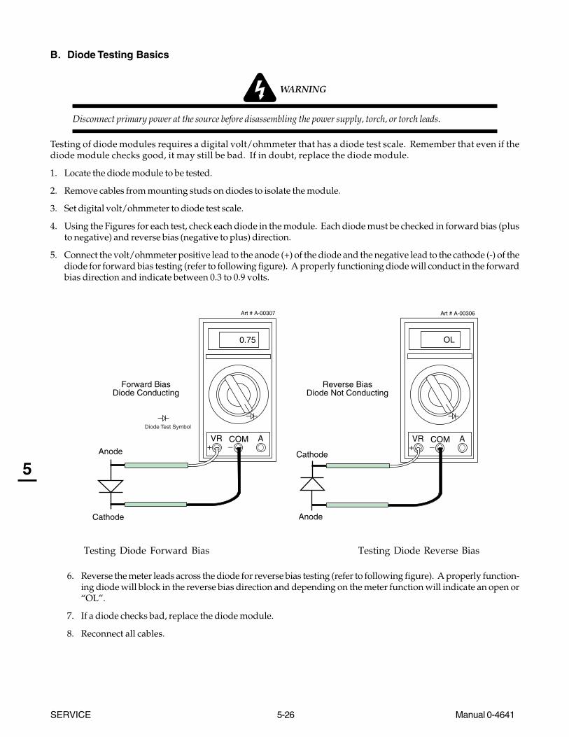
SERVICE 5-26 Manual 0-4641
5
B. Diode Testing Basics
WARNING
Disconnect primary power at the source before disassembling the power supply, torch, or torch leads.
Testing of diode modules requires a digital volt/ohmmeter that has a diode test scale. Remember that even if thediode module checks good, it may still be bad. If in doubt, replace the diode module.
1. Locate the diode module to be tested.
2. Remove cables from mounting studs on diodes to isolate the module.
3. Set digital volt/ohmmeter to diode test scale.
4. Using the Figures for each test, check each diode in the module. Each diode must be checked in forward bias (plusto negative) and reverse bias (negative to plus) direction.
5. Connect the volt/ohmmeter positive lead to the anode (+) of the diode and the negative lead to the cathode (-) of thediode for forward bias testing (refer to following figure). A properly functioning diode will conduct in the forwardbias direction and indicate between 0.3 to 0.9 volts.
0.75
VR COM A
Art # A-00307
Anode
Cathode
Forward BiasDiode Conducting
+ _
Diode Test Symbol
OL
VR COM A
Art # A-00306
Anode
Cathode
Reverse BiasDiode Not Conducting
+ _
Testing Diode Forward Bias Testing Diode Reverse Bias
6. Reverse the meter leads across the diode for reverse bias testing (refer to following figure). A properly function-ing diode will block in the reverse bias direction and depending on the meter function will indicate an open or“OL”.
7. If a diode checks bad, replace the diode module.
8. Reconnect all cables.

Manual 0-4641 5-27 SERVICE
5
C. Diode Module Board Tests
WARNING
Disconnect primary power at the source before taking any resistance checks.
1. Input Diode Test
a. Disconnect input AC power.
b. Check Input Diode for shorted input diode. With an ohmmeter set on the diode range make the following checks fromMain PC Board to Input Diode:
For 400-Volt, 415-Volt, 460-Volt, and 600-Volt Power Supplies: For 208/230-Volt Power Supplies:
Meter + Meter - IndicationE15 E1 Diode DropE1 E15 Open
E15 E2 Diode Drop E2 E15 OpenE15 E3 Diode DropE3 E15 OpenE7 E1 OpenE1 E7 Diode DropE7 E2 OpenE2 E7 Diode DropE7 E3 OpenE3 E7 Diode DropE7 E15 Open
E15 E7 Diode Drop*
400V, 415V, 460V, and 600V Input Diode Indications
* Indication can be twiceother indications.
Meter + Meter - IndicationE7 E1 OpenE1 E7 Diode Drop
E15 E1 Diode DropE1 E15 Open
E15 E7 Diode Drop*E7 E15 Open
208/230V Input Diode Indications
* Indication can be twiceother indications.
c. The meter should indicate a diode drop in one direction and an open in the other direction for each check. Replace theInput Diode Module Board if the readings do not match the chart.
d. If Input Diode Module Board is shorted, make the following checks with an ohmmeter at the Main Contactor (W1):
Meter (+) Meter (-) IndicationL1 T1 OpenL2 T2 OpenL3 T3 Open
If any test has resistance, then replace the Main Contactor.

SERVICE 5-28 Manual 0-4641
5
2. Output Diode Module Board Circuit Test
a. Use an ohmmeter set on the diode function and make the following measurements on the Output Diode Module Boardsto Power Output PC Board.
IndicationMeter + Meter - Meter + Meter -
E37 E58 E36 E57 Diode Drop *E58 E37 E57 E36 OpenE37 E47 E36 E49 Diode DropE47 E37 E49 E36 OpenE58 E47 E57 E49 OpenE47 E58 E49 E57 Diode Drop
Output Diode A Output Diode B
* Indication can be twice other indications.
b. The meter should indicate a diode drop in one direction and an open in the other direction for each check.Replace the Output Diode Module Board(s) if the readings do not match the chart.
3. IGBT Module Board Circuit Test
a. Use an ohmmeter set on the diode function and make the following measurements on the IGBT Module Board(s) to theMain PC Board.
IndicationMeter + Meter - Meter + Meter -
E10 E4 E27 E23 Diode DropE4 E10 E23 E27 Open
E10 E20 E27 E30 OpenE20 E10 E30 E27 Diode DropE4 E20 E23 E30 Open
E20 E4 E30 E23 Diode Drop *
IGBT PCB A IGBT PCB B
* Indication can be twice other indications.
b. The meter should indicate a diode drop in one direction and an open in the other direction for each check.Replace IGBT Module Board(s) if readings are not the same as the chart.
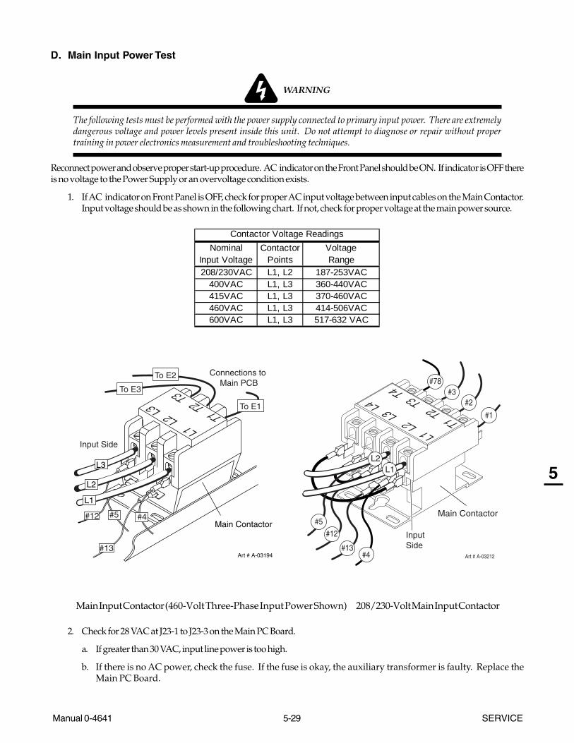
Manual 0-4641 5-29 SERVICE
5
D. Main Input Power Test
WARNING
The following tests must be performed with the power supply connected to primary input power. There are extremelydangerous voltage and power levels present inside this unit. Do not attempt to diagnose or repair without propertraining in power electronics measurement and troubleshooting techniques.
Reconnect power and observe proper start-up procedure. AC indicator on the Front Panel should be ON. If indicator is OFF thereis no voltage to the Power Supply or an overvoltage condition exists.
1. If AC indicator on Front Panel is OFF, check for proper AC input voltage between input cables on the Main Contactor.Input voltage should be as shown in the following chart. If not, check for proper voltage at the main power source.
NominalInput Voltage
ContactorPoints
VoltageRange
208/230VAC L1, L2 187-253VAC400VAC L1, L3 360-440VAC415VAC L1, L3 370-460VAC460VAC L1, L3 414-506VAC600VAC L1, L3 517-632 VAC
Contactor Voltage Readings
Art # A-03194
Main Contactor
#13
#5
L1 L2 L
3T1 T2 T3To E3
Connections to Main PCB
#4#12
To E1
To E2
Input Side
L1
L3
L2
Art # A-03212
L1 L2 L3 L4
T1 T2 T3 T4
#13
#12
#78
L1L2
InputSide
#5
#4
#3#2
#1
Main Contactor
Main Input Contactor (460-Volt Three-Phase Input Power Shown) 208/230-Volt Main Input Contactor
2. Check for 28 VAC at J23-1 to J23-3 on the Main PC Board.
a. If greater than 30 VAC, input line power is too high.
b. If there is no AC power, check the fuse. If the fuse is okay, the auxiliary transformer is faulty. Replace theMain PC Board.

SERVICE 5-30 Manual 0-4641
5
E. Gas Solenoid Circuit Test
Make the following voltage checks and replace the faulty part as required.
1. Place the RUN / RAPID AUTO RESTART / SET Switch to the SET position.
2. Measure for 28 VAC across Solenoid wires #8 and #9. Refer to System Schematic in Appendix Section.
• If 28 VAC is present, replace Solenoid/Pressure Switch Assembly.
• If 28 VAC is not present, check for 65 psi (4.5 bar) at the pressure regulator.
3. Check for less than 2 vdc at P1-7 to TP1 on Logic Board.
• If less than 2 vdc, replace Main PC Board.
• If more than 2 vdc, replace Logic PC Board.
F. Output Power Tests
1. No DC Output
a. Activate the torch.
• If INV ON indicator D13 on Logic PC Board does not turn ON, then replace the Logic PCB.
• If the INV ON indicator D13 blinks ON then OFF immediately, perform the following test:
WARNING
The following tests must be performed with the power supply connected to primary input power. There areextremely dangerous voltage and power levels present inside this unit. Do not attempt to diagnose or repairwithout proper training in power electronics measurement and troubleshooting techniques.
The next step will defeat the safety interlock feature. Proceed with caution.
b. Remove the tip and electrode from the torch. Attach the work lead to the pilot return (E35 or E62) on the Output PowerBoard. Activate the torch switch. Gas should flow, then stop after 2 seconds. Front panel DC indicator shouldturn on.
c. Measure open circuit voltage between E61(+) to E43 (-) at the Output Power PC Board. Voltage should be greater than200 V. If voltage is less than 10 V, refer to the diode test measurements in Section 5.10-C.
2. Gate Drive & Sensing
a. After checking all previous steps, jumper TP1 to TP7 on the Logic PCB. Refer to Logic Board layout.
b. When the unit is turned on, the DC light should remain ON.
c. Activate the torch. After two seconds INV ON Indicator (D13) on the Logic PCB should come on and remain on.
• If INV ON indicator does not remain on, replace Logic PCB.
• If INV ON indicator remains on, then check for at least 2 vdc between TP-1 to TP-11 and between TP-1 to TP-10 on theLogic PCB. Refer to Logic Board Layout.
• If no voltage, replace Logic PC Board.
• If voltage is correct, measure for at least 2 vdc between points as in the following chart:
E11 J2A E11 J2BE19 J10A E19 J10B
IGBT A IGBT B
• If voltage is 0, replace Main PCB.

Manual 0-4641 5-31 SERVICE
5
5.09 Power Supply Major External Parts Replacement
WARNING
Disconnect primary power to the system before disassembling the torch, leads, or power supply.
For replacement of parts not covered in this section, instructions are provided with the replacement part.
A. Cover Removal
1. Remove the upper screws which secure the cover to the main assembly.
NOTE
There is a ground wire connection to the inside of the unit. There is no need to disconnect the ground wire, unlessthere is a need for more room to work.
Art # A-04510
Lowerscrews
Upper screws
Ground wire
Lowerscrews
2. Loosen, but do not remove, the lower screws, then carefully pull the Cover up and away from the unit.

SERVICE 5-32 Manual 0-4641
5
B. Tube Handle Replacement
1. Remove the power supply cover per Section 5.09-A.
2. Remove the four bolts and star washers securing the tube handles to the base of the unit.
3. Move the input power cable, torch leads and work cable inside the handle, then lift the base of the unit away from theTube Handle.
4. With a rubber mallet, separate the two handle ends as shown below.
5. Install the replacement Tube Handle by reversing the above steps.
6. Reinstall the power supply cover.
Art # A-02847
C Cover Installation
1. Reconnect the ground wire, if necessary.
2. Place the cover onto the power supply so that slots in the bottom edges of the cover engage the lower screws.
3. Tighten lower screws.
4. Reinstall and tighten the upper screws.
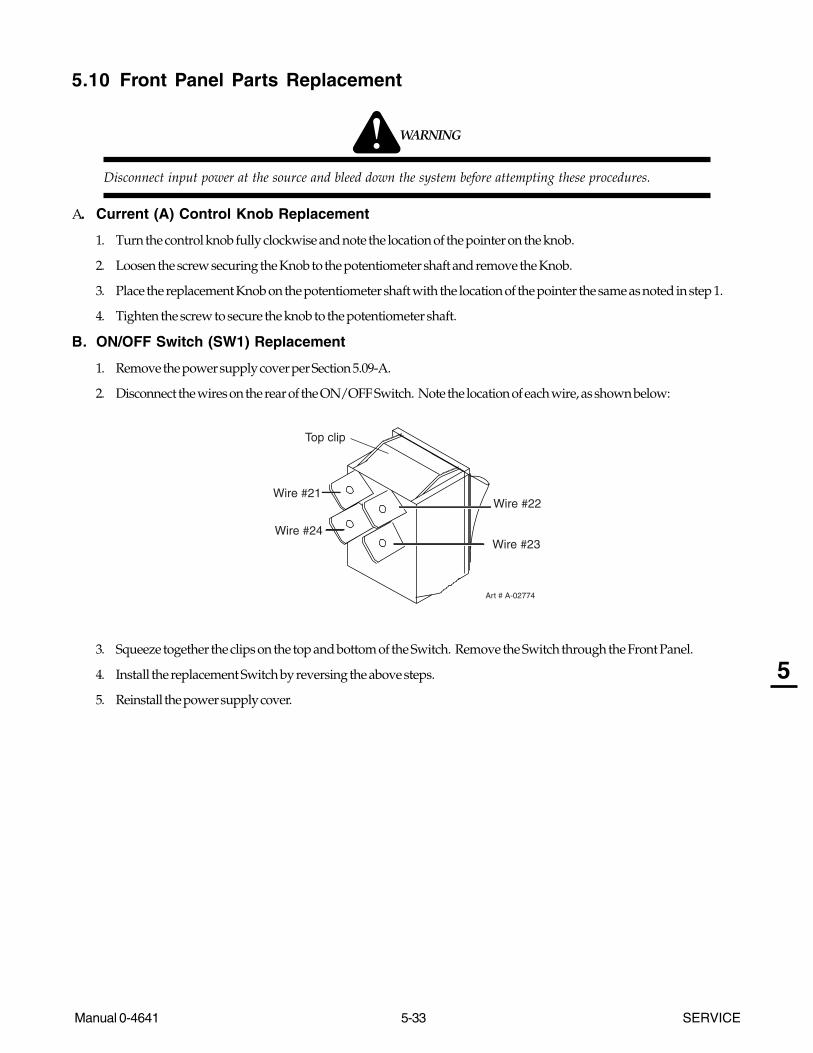
Manual 0-4641 5-33 SERVICE
5
5.10 Front Panel Parts Replacement
WARNING
Disconnect input power at the source and bleed down the system before attempting these procedures.
A. Current (A) Control Knob Replacement
1. Turn the control knob fully clockwise and note the location of the pointer on the knob.
2. Loosen the screw securing the Knob to the potentiometer shaft and remove the Knob.
3. Place the replacement Knob on the potentiometer shaft with the location of the pointer the same as noted in step 1.
4. Tighten the screw to secure the knob to the potentiometer shaft.
B. ON/OFF Switch (SW1) Replacement
1. Remove the power supply cover per Section 5.09-A.
2. Disconnect the wires on the rear of the ON/OFF Switch. Note the location of each wire, as shown below:
Art # A-02774
Wire #21
Wire #24
Top clip
Wire #22
Wire #23
3. Squeeze together the clips on the top and bottom of the Switch. Remove the Switch through the Front Panel.
4. Install the replacement Switch by reversing the above steps.
5. Reinstall the power supply cover.
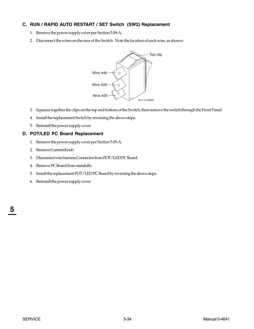
SERVICE 5-34 Manual 0-4641
5
C. RUN / RAPID AUTO RESTART / SET Switch (SW2) Replacement
1. Remove the power supply cover per Section 5.09-A.
2. Disconnect the wires on the rear of the Switch. Note the location of each wire, as shown:
Art # A-03906
Wire #25
Wire #26
Top clip
Wire #46
3. Squeeze together the clips on the top and bottom of the Switch, then remove the switch through the Front Panel.
4. Install the replacement Switch by reversing the above steps.
5. Reinstall the power supply cover.
D. POT/LED PC Board Replacement
1. Remove the power supply cover per Section 5.09-A.
2. Remove Current Knob .
3. Disconnect wire harness Connector from POT/LED PC Board.
4. Remove PC Board from standoffs.
5. Install the replacement POT/LED PC Board by reversing the above steps.
6. Reinstall the power supply cover.
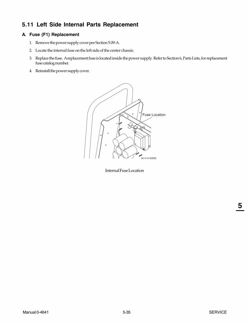
Manual 0-4641 5-35 SERVICE
5
5.11 Left Side Internal Parts Replacement
A. Fuse (F1) Replacement
1. Remove the power supply cover per Section 5.09-A.
2. Locate the internal fuse on the left side of the center chassis.
3. Replace the fuse. A replacement fuse is located inside the power supply. Refer to Section 6, Parts Lists, for replacementfuse catalog number.
4. Reinstall the power supply cover.
Art # A-03002
Fuse Location
Internal Fuse Location

SERVICE 5-36 Manual 0-4641
5
B. Main Input Contactor (W1) Replacement
1. Remove the power supply cover per Section 5.09-A.
2. Label all wires connected to the Input Contactor.
3. Disconnect wires to the Input Contactor from the input cable.
4. Disconnect all other wires connected to the Input Contactor.
5. Remove the two nuts and washers securing the Input Contactor to the base of the power supply.
6. Position the replacement Input Contactor with the row of connectors labeled L toward the rear of the Power Supply.Fasten in place with the hardware removed previously.
7. Complete the wiring connections as shown.
NOTE
It is important that wires are installed correctly, as shown, to prevent damage to the unit.
8. Reinstall the power supply cover.
Art # A-03194
Main Contactor
#13
#5
L1 L2 L
3T1 T2 T3To E3
Connections to Main PCB
#4#12
To E1
To E2
Input Side
L1
L3
L2
Art # A-03212
L1 L2 L3 L4
T1 T2 T3 T4
#13
#12
#78
L1L2
InputSide
#5
#4
#3#2
#1
Main Contactor
400-Volt, 415-Volt, 460-Volt, and 600-Volt Input Contactor 208 / 230-Volt InputContactor
(3-phase input power connections shown)

Manual 0-4641 5-37 SERVICE
5
C. Logic PC Board Replacement
Follow the antistatic instructions provided with the replacement part. The Logic PC Board connects to the Main PCBoard through an extender board perpendicular to both boards.
1. Remove the power supply cover per Section 5.09-A.
2. Remove the bolts in each corner of the Logic PC Board.
3. Detach the Logic PC Board and the extender board from the Main Power PC Board. Detach the extender board from theLogic Board.
4. Install the replacement Logic PC Board by reversing the above steps. The pins on the right edge of the Logic PC Boardmust fully engage the sockets on the edge of the extender board. The extender board must fully engage sockets on theMain Power PC Board.
D. IGBT Circuit Board or Input Diode Board Replacement
Follow the antistatic instructions provided with the replacement part. The Power Supply includes two IGBT Circuit PC Boards.
NOTE
Follow the electrostatic discharge instructions provided with the replacement component to prevent damage tothe component.
Thermal pads, heatsinks, and the large flat surface on the back of diodes and IGBTs must be kept clean. Diodes andIGBTs must not be bent or allowed to pick up any foreign material. A very clean installation between the moduleand the heatsink or chassis is essential for proper operation.
1. Remove the power supply cover per Section 5.09-A.
2. Turn the Power Supply onto its side.
3. Locate the IGBT Circuit PC Boards or Input Diode mounted within the Main Power PC Board. Refer to Appendix pagesfor location and position.
4. For IGBTs, remove the small jumpers between the IGBT and the Main PC Board. Transfer these jumpers to the replace-ment IGBT. Label, then remove all other wire connections to the Board(s) being replaced. Note the routing of wires.Ensure that the wires are put back in the same place when installing the replacement module.
5. Remove screw(s) securing PC Board(s) to the heatsink and remove board(s) from the Power Supply.
6. Use isopropyl alcohol and a clean rag to clean the heatsink or chassis area behind the component being replaced. Cleanthe large flat surface on the back of the replacement component. Do not scratch or abrade the surface.
7. The thermal pad(s), provided with the replacement part, is a thin metal pad. Remove any loose protective paper coveringsfrom the pad(s).
NOTE
Protective coverings must be removed from the thermal pads. Installing thermal pads with protective coverings inplace will cause equipment damage or failure.
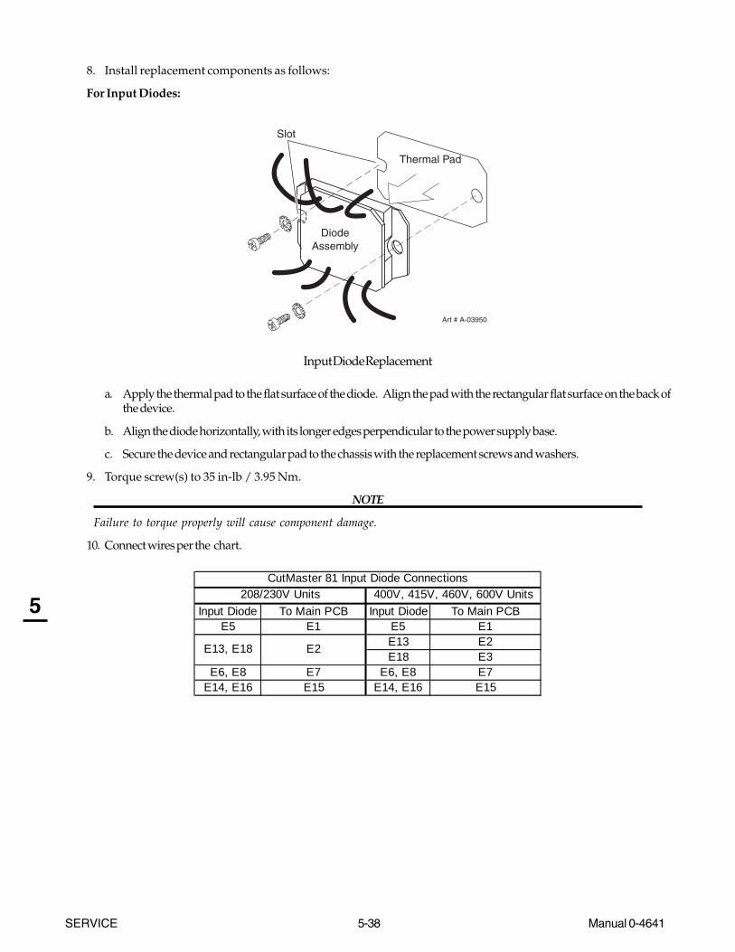
SERVICE 5-38 Manual 0-4641
5
8. Install replacement components as follows:
For Input Diodes:
Diode Assembly
Art # A-03950
Thermal Pad
Slot
Input Diode Replacement
a. Apply the thermal pad to the flat surface of the diode. Align the pad with the rectangular flat surface on the back ofthe device.
b. Align the diode horizontally, with its longer edges perpendicular to the power supply base.
c. Secure the device and rectangular pad to the chassis with the replacement screws and washers.
9. Torque screw(s) to 35 in-lb / 3.95 Nm.
NOTE
Failure to torque properly will cause component damage.
10. Connect wires per the chart.
Input Diode To Main PCB Input Diode To Main PCBE5 E1 E5 E1
E13 E2E18 E3
E6, E8 E7 E6, E8 E7E14, E16 E15 E14, E16 E15
400V, 415V, 460V, 600V Units208/230V UnitsCutMaster 81 Input Diode Connections
E13, E18 E2

Manual 0-4641 5-39 SERVICE
5
For IGBTs:
a. Apply a round thermal pad to the heatsink with a small piece of light-duty tape. The tape must cover no more than 1/8" (3 mm) of the edge of the thermal pad. Use the screw hole in the heatsink as a guide to position the board.
Washer
Screw
Output Diodeor IGBT
Round Thermal Pad
Art # A-03702
Tape
Tape
b. Secure replacement board(s) with the screw removed previously. Ensure that the washer is under the head of thescrew.
9. Torque screw(s) to 17 in-lb. (1.9 Nm).
NOTE
Failure to torque properly will cause component damage.
10. Connect wires per the chart.
IGBT AConnector
To Main PCBConnector
IGBT BConnector
To Main PCBConnector
J3 J25 J3 J31J7 J30 J7 J26
E9, E11 E10 E9, E11 E27E19, E21 E20 E19, E21 E30E12, E17 E4 E12, E17 E23
IGBT A IGBT BCutMaster 81 IGBT Connections
11. Stand the unit upright; reinstall the cover.

SERVICE 5-40 Manual 0-4641
5
E. Main PC Board Replacement
Follow the antistatic procedures provided with the replacement part.
1. Remove the power supply cover per Section 5.09-A.
2. Remove the Logic PC Board.
3. Remove the POT/LED PC Board.
4. Disconnect all wire and cable connections to the Main PC Board, including the connections from the three smaller PCBoards. Refer to the Main PC Board Wiring Diagrams in the Appendix pages if necessary.
5. Remove the two long Transformer screws securing the Auxiliary Transformer to the Center Chassis.
6. Remove the other screws securing the PC Board to the Center Chassis.
7. Carefully remove the original PC Board.
8. Install the replacement PC Board by reversing steps above. It may be easier to install the PC Board if the Power Supplyis turned on its right side first. Torque the screws to 17 inch-pounds (1.9 Nm).
Art # A-03909
Auxiliary Transformer
IGBT OutputDiode
AttachmentScrews
1 3
9
54
2
6 7
8
10 11
12
9. Reconnect all wiring. Refer to the Appendix pages in this manual for wiring details.
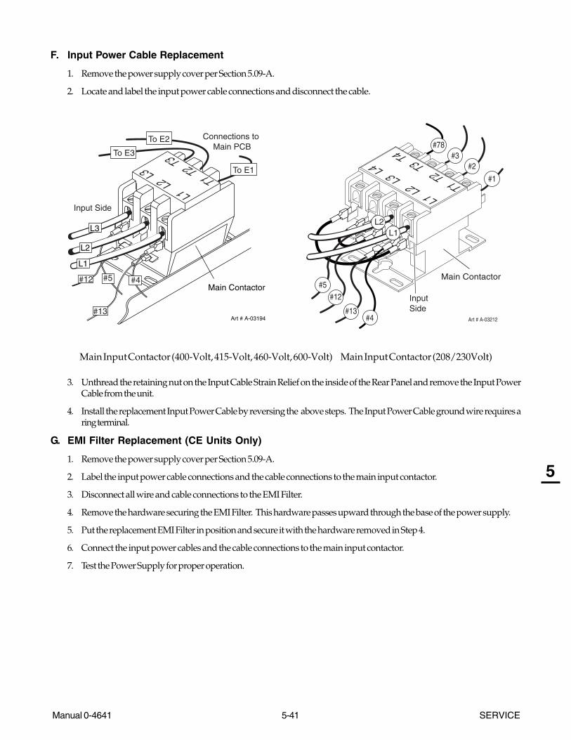
Manual 0-4641 5-41 SERVICE
5
F. Input Power Cable Replacement
1. Remove the power supply cover per Section 5.09-A.
2. Locate and label the input power cable connections and disconnect the cable.
Art # A-03194
Main Contactor
#13
#5
L1 L2 L
3T1 T2 T3To E3
Connections to Main PCB
#4#12
To E1
To E2
Input Side
L1
L3
L2
Art # A-03212
L1 L2 L3 L4
T1 T2 T3 T4
#13
#12
#78
L1L2
InputSide
#5
#4
#3#2
#1
Main Contactor
Main Input Contactor (400-Volt, 415-Volt, 460-Volt, 600-Volt) Main Input Contactor (208/230Volt)
3. Unthread the retaining nut on the Input Cable Strain Relief on the inside of the Rear Panel and remove the Input PowerCable from the unit.
4. Install the replacement Input Power Cable by reversing the above steps. The Input Power Cable ground wire requires aring terminal.
G. EMI Filter Replacement (CE Units Only)
1. Remove the power supply cover per Section 5.09-A.
2. Label the input power cable connections and the cable connections to the main input contactor.
3. Disconnect all wire and cable connections to the EMI Filter.
4. Remove the hardware securing the EMI Filter. This hardware passes upward through the base of the power supply.
5. Put the replacement EMI Filter in position and secure it with the hardware removed in Step 4.
6. Connect the input power cables and the cable connections to the main input contactor.
7. Test the Power Supply for proper operation.
SERVICE 5-42 Manual 0-4641
5
5.12 Right Side Internal Parts Replacement
A. Fan Replacement (M1, M2)
1. Remove the power supply cover per Section 5.09-A.
2. Label, then carefully remove the wiring connectors from the terminals on the Fans.
3. Disconnect the Work Cable from terminal E61 on the Power Output Board.
4. Remove one bolt from the Front Panel of the Power Supply, near the Control Panel. Pull the Front Panel slightly away fromthe Power Supply.
5. Remove one nut from a stud at the bottom of the Fan Assembly Panel.
6. Lift the Fan Assembly Panel and pull it out of the Power Supply.
7. Remove two bolts per Fan. Set the Fan(s) aside.
8. Install the replacement Fan Assembly as follows:
a. Fasten Fan(s) in position with the wiring connectors at the bottom of the Fan(s).
NOTE
Only two screws are needed to attach the Fan to the Fan Panel. They can be installed in any two holes providedthey are opposite each other. For grounding purposes, one of those screws must be installed with a star washer.
b. Place the Fan Assembly Panel in position in the Power Supply.
1. The inner edge of the Panel has tabs that engage slots in the center chassis. Ensure that these tabs fully engagein the chassis.
2. Press the Panel downward. Press the bottom flange fully against the bottom panel of the Power Supply.
3. Ensure that the hole in the bottom flange of the Fan Assembly Panel engages the mounting stud.
c. Replace nut on the bottom mounting stud.
d. Ensure that the Fan Panel's top flange is fully against the top forward edge of the Heatsink Shroud.
e. Press the front panel of the Power Supply against the Fan Panel, and fasten in place with the bolt removed in Step 2.
f. Secure the nut on the stud at the bottom of the Fan Panel.
9. Re-connect the wires to the Fan Assemblies.
10. Pass the Work Cable through the hole in the bottom of the Fan Panel. Ensure that the grommet is in place in the hole.
11. Connect the Work Cable to terminal E61 on the Power Output PC Board. Secure the Work Cable Strain Relief.
12. Re-install the Power Supply Cover.

Manual 0-4641 5-43 SERVICE
5
B. Work Cable Replacement
1. Remove the cover per Section 5.09-A.
2. Disconnect the Work Cable from the E61 (WORK) terminal on the Power Output PC Board, located on the right side of theunit.
3. Squeeze the top and bottom of the Work Cable Strain Relief and remove from the Front Panel.
4. Remove Work Cable from the unit.
5. Install the replacement Work Cable.
a. Ensure that the replacement Work Cable passes through the grommet in the Fan Assembly Panel.
b. Secure the Cable to the Work terminal on the Power Output PC Board and securing the strain relief.
C. Pilot PC Board Replacement
The Pilot PC Board mounts to the Power Supply center chassis. Refer to Pilot Board Layout in the Appendix.
1. Remove the power supply cover per Section 5.09-A.
2. Label and disconnect wires from Pilot PC Board terminals E58 and E62. Disconnect the wire harness from receptacle J28.
3. Remove the hardware securing the Pilot PC Board to the power supply center chassis. Remove the Pilot PC Board.
4. Position the replacement Pilot PC Board against the standoffs fastened to the center chassis. Note that the Pilot PC Boardmounts with its printed text upside down. Fasten the Pilot Board to the standoffs with the hardware removed previously.Torque the hardware to 18 in-lbs (2.04 Nm).
5. Reconnect the wires to the Pilot PC Board. Wire #58 connects to terminal E58; wire #62 connects to terminal E62. Ensurethat the wire harness connector is fully seated in receptacle J28.
6. Reinstall the power supply cover.

SERVICE 5-44 Manual 0-4641
5
D. Pressure Switch/Solenoid Assembly Replacement
The Pressure Switch and Solenoid Valve are one Assembly. Disconnect primary input power and bleed down the system.
1. Remove the power supply cover per Section 5.09-A.
2. Disconnect the following wires:
a. Wires #10 and #11 from the Pressure Switch Assembly.
b. Wires #8 and #9 from the Solenoid Assembly.
3. Push the clip on the front of the Heatsink Shroud to the left to release the Solenoid Assembly. Dislodge the Assemblyfrom underneath the clip on the top of the Heatsink Shroud.
HeatsinkShroud
Dislodge SolenoidAssembly
Push Clipto the left to
release SolenoidAssembly
Art # A-03705
2
3
1
4. Release the hose from the Adapter Fitting on the input side of the Solenoid Assembly. Hold a wrench or similar toolagainst the locking ring on the Fitting, then pull on the hose to release it.
5. Release the hose from the Adapter Fitting on the output side of the Solenoid Assembly.
6. Install the replacement Pressure Switch/Solenoid Assembly by reversing steps 2-5. Once installed, the Solenoid Assem-bly should fit securely on the Heatsink Shroud. It should not be moveable.
7. Re-install the power supply cover.

Manual 0-4641 5-45 SERVICE
5
E. Heatsink Shroud Assembly Removal
The Heatsink Shroud Assembly must be disengaged for access to either the Main Transformer or the Output Inductor. Followthese steps for access to either component.
1. Remove the power supply cover per Section 5.09-A.
2. Release the tab on the vertical face of the Heatsink Shroud securing the Solenoid/Pressure Switch Assembly in position.
3. Remove the gas hose from the Regulator Fitting on the back panel of the Power Supply by pressing on the locking ringon the elbow fitting, while pulling on the hose.
4. Remove the Power Supply Back Panel per subsection 5.07-D.
Remove the grommets from the two holes on the right (rear) edge of the Heatsink Shroud.
5. Remove the Fan Assembly per subsection 5.08C.
6. Label and disconnect the wires connected to the Pilot PC Board.
7. Remove the hardware securing the Pilot PC Board in place. Pull the PC Board off the center chassis.
8. Label and disconnect wires No. 45, 47, 49, and 52 from the Power Output PC Board.
9. Disconnect the wires from the Output Inductor to terminal E43 on the Power Output PC Board.
Disconnect the torch receptacle ground wire connected to the center chassis.
10. Remove nuts on two studs at the top corners of the Heatsink Shroud, and nuts on two studs on the bottom flange of theHeatsink Shroud.
12. Remove the Heatsink Shroud as follows:
a. Use the open left end of the Heatsink Shroud and the Pressure Switch/Solenoid opening as handles.
b. Pull the Heatsink Shroud away from the center chassis, and then up. It may be necessary to pry the top and bottomflanges of the Heatsink Shroud slightly to release them from their mounting studs. Movement will be limited by thewiring harness.

SERVICE 5-46 Manual 0-4641
5
F. Main Transformer Removal and Replacement
1. Disengage the Heatsink Shroud per Paragraph E.
2. Disconnect wires #27 and 32, connected to terminals E27 and E32 on the Main Power PC Board. Pull these wires throughthe hole in the center chassis.
3. Remove the transformer.
a. Lift the Main Transformer slightly. Swing its left edge away from the center chassis. Pull its right edge away from thecenter chassis.
b. Lift it out of the Power Supply through the opening at the rear of the Power Supply.
4. Position the replacement Main Transformer behind the Heatsink Shroud Assembly. Position its wires at the right edge(as you face it) of the transformer.
5. Install the replacement transformer as follows:
a. Pass the tabs on the right edge of the base of the transformer into slots in the center chassis of the Power Supply.
b. Swing the transformer against the chassis, and pass the tabs on the left edge of the base into slots in the chassis.Press the transformer downward to lock it into position.
c. Check for proper installation; the transformer should remain securely in place.
6. Pass wires #27 and 32 through the hole in the center of the main chassis. Connect wire #27 to terminal E27 and wire #32to terminal E32 on the Main Power PC Board.
7. Reinstall the Heatsink Shroud Assembly per sub-section H.
G. Output Inductor Assembly Removal and Replacement
1. Disengage the Heatsink Shroud per paragraph E.
2. Disconnect the wires to the thermal switch on the Output Inductor.
3. Remove hex nuts at the left forward and right rear corners of the Inductor base.
4. Remove the Inductor as follows:
a. Note the position of the wires leading from the Inductor.
b. Lift out the Inductor through the opening at the rear of the Power Supply. It may be necessary to lift the Main Transformerslightly to create room for the Inductor to pass through the rear opening.
5. Install the replacement Inductor.
a. Put the replacement Inductor in place, with the wires oriented the same way as the original Inductor.
b. Secure the Inductor in place with hex nuts at opposite corners of the Inductor base.
6. Reconnect the wires to the thermal switch on the Output Inductor.
7. Replace the Heatsink Shroud per paragraph I.

Manual 0-4641 5-47 SERVICE
5
H. Heatsink Shroud Assembly Replacement
1. Pass transformer wires #45 and 49 through the upper hole in the right (rear) edge of the Heatsink Shroud. Pass trans-former wires #47 and 52 through the lower hole.
2. Route wires as follows:
a. Pass the red wires from the output inductor through the upper hole in the right (rear) edge of the Heatsink Shroud.
b. Pass the black wires from the output inductor through the lower hole in the right (rear) edge of the Heatsink Shroud.Refer to Appendix 11, Power Output Board Layout.
c. Pass the wires from the temperature switch on the Output Inductor through the upper hole in the Shroud.
3. Re-install the Heatsink Shroud as follows:
a. Lift the Heatsink Shroud (Assembly) into position. Studs on the Power Supply base pass through holes in thebottom flange of the Shroud.
b. Swing the top edge of the Shroud Assembly into place. Studs on the Center Chassis of the Power Supply passthrough holes in the top flanges of the Shroud.
c. Ensure that the rubber feet on the Main Transformer engage holes in the Shroud.
d. Put hex nuts on the studs. Tighten the nuts on the right (rear) top and bottom studs. Leave the nuts on the left(forward) studs loose temporarily.
4. Put the Fan Assembly in place per subsection 5.12-A. Reconnect the work cable to terminal E61 on the Power OutputPC Board.
5. Tighten the nuts securing the left edge of the Heatsink Shroud Assembly. The stud and nut on the bottom left edgefasten a wire stay to the Power Supply.
6. Replace the grommets around the wire harnesses passing through the right (rearward) edge of the Heatsink Shroud.
7. Reinstall the Pilot Board. Reconnect the wires to the Pilot Board.
Reconnect the torch receptacle ground wire to the center chassis.
9. Replace the Pressure Switch/Solenoid Assembly. This assembly fits into a slot in the top horizontal surface of theHeatsink Shroud. A notched pin holds the assembly in place.
10. Connect the gas hose between the Regulator/Filter Assembly and the Gas Pressure Switch/Solenoid Assembly.
11. Connect wiring to the Output Power PC Board. Refer to the Appendix pages for wiring layout.
12. Replace the Power Supply rear panel per subsection 5.07-D.
This concludes the replacement procedures.

SERVICE 5-48 Manual 0-4641
5
This Page Left Blank
Manual 0-4641 6-1 PARTS LISTS
6
SECTION 6:PARTS LISTS
6.01 Introduction
A. Parts List Breakdown
The parts list provide a breakdown of all replaceable components. The parts lists are arranged as follows:
Section 6.03 Complete Power Supply Replacements
Section 6.04 Power Supply Basic Replacement Parts
Section 6.05 Power Supply Options and Accessories
Section 6.06 Power Supply Major External Replacement Parts
Section 6.07: Power Supply Front Panel Replacement Parts
Section 6.08: Power Supply Left Side Replacement Parts
Section 6.09: Power Supply Rear Panel Replacement Parts
Section 6.10: Power Supply Right Side Replacement Parts
Section 6.11: Torch Replacement Parts (SL100 Torch - no Solenoid on Mounting Tube)
Section 6.12: Torch Replacement Parts (SL100SV Torch - with Solenoid on Mounting Tube)
Section 6.13: Torch Consumable Parts
Section 6.14: Torch Spare Parts Kits
Section 6.15: Complete Torch Replacements
Section 6.16: Torch Options and Accessories
NOTE
Parts listed without item numbers are not shown, but may be ordered by the catalog number shown.
B. Returns
If a product must be returned for service, contact your distributor. Materials returned without proper authorizationwill not be accepted.
6.02 Ordering Information
Order replacement parts by catalog number and complete description of the part or assembly, as listed in the partslist for each type item. Also include the model and serial number of the power supply. Address all inquiries to yourauthorized distributor.
6.03 Complete Power Supply Replacement
The following items are included with the replacement power supply: work cable & clamp, input power cable, gas pressureregulator / filter, and operating manual.
Qty Description Catalog #
CutMaster 81 Automation Power Supply1 208 / 230VAC, Single-Phase, 50 / 60Hz, with input power cable and plug 3-1121-11 400VAC, Three - Phase, 50 /60Hz, with input power cable 3-1121-31 400VAC, Three - Phase, 50 Hz , with input power cable, CE 3-1121-41 415VAC, Three - Phase, 50 Hz , with input power cable, CE 3-1121-61 460VAC, Three - Phase, 60 Hz, with input power cable 3-1121-21 600VAC, Three - Phase, 60 Hz, with input power cable 3-1121-5

PARTS LISTS 6-2 Manual 0-4641
6
6.04 Power Supply Basic Replacement Parts
Qty Description Catalog #
Fuse1 for 208 / 230VAC Power Supply 9-85881 for 400 / 415 VAC Power Supply 9-86021 for 460 VAC Power Supply 9-85831 for 600 VAC Power Supply 9-86381 Regulator / Filter Assembly Replacement Element 9-4414
6.05 Power Supply Options and Accessories
Qty Description Catalog #
1 Two-Stage Filter Kit (includes Hose & Mounting Screws) 7-75001 Bracket, Filter Mounting (not shown) 9-75351 Two-Stage Air Filter Assembly 9-75271 First Stage Cartridge 9-10211 Second Stage Cartridge 9-10221 Single-Stage Filter Kit (includes Filter & Hose) 7-75071 Replacement Filter Body 9-77401 Replacement Filter Hose (not shown) 9-77422 Replacement Filter Element 9-7741
1 Extended Work Cable ( 50 ft /15.2 m ) with Clamp 9-85291 Multi-Purpose Cart 7-88881 25' / 7.6 m CNC Interface Cable 9-83121 50' / 15.2 m CNC Interface Cable 9-83131 75' / 22.8 m CNC Interface Cable 9-83151 100' / 30.4 m CNC Interface Cable 9-83161 125' / 38.0 m CNC Interface Cable 9-83171 Vinyl Cover 9-7072
Art # A-02476
FilterElement
(Cat. No. 9-7741)
Housing
Cover
BarbedFitting
Spring
Assembled FilterO-ring
(Cat. No. 9-7743) First & Second
StageCartridges (as marked)
Art # A-02942
Single-Stage Filter Kit Optional Two-Stage Filter Kit

Manual 0-4641 6-3 PARTS LISTS
6
NOTE: Illustration may vary slightly from unit.
6.06 Power Supply Major External Replacement Parts
Item # Qty Description Catalog #
1 1 Cover with labels 9-79972 Rear Panel (provide data tag information when ordering)
1 For 208/230-Volt Power Supplies 9-83231 For 400-Volt, 415-Volt, 460-Volt, and 600-Volt Power Supplies 9-8322
2 1 Tube, roll handle 9-7998
Art # A-03709
3
3
1
2

PARTS LISTS 6-4 Manual 0-4641
6
6.07 Power Supply Front Panel Replacement Parts
Item# Qty Description Ref. # Catalog #
1 1 Knob, Fluted, Skirted, 0.250 I.D. 9-85272 1 On/Off Rocker Switch SW1 8-32583 1 Run / Rapid Auto Restart / Set Switch SW2 9-10424 1 Assembly, Pot / LED PC Board 9-80045 1 Work Cable, #6 AWG, with Clamp, 20 Ft. (6.1 m) See Note6 1 Work Cable, #6 AWG, with Clamp, 20 Ft. (6.1 m) 9-8528
NOTE: Illustration may vary slightly from unit.
Art # A-06756
1
2
3
4
5
6
Note:
Item # 6 replaces Item #5.
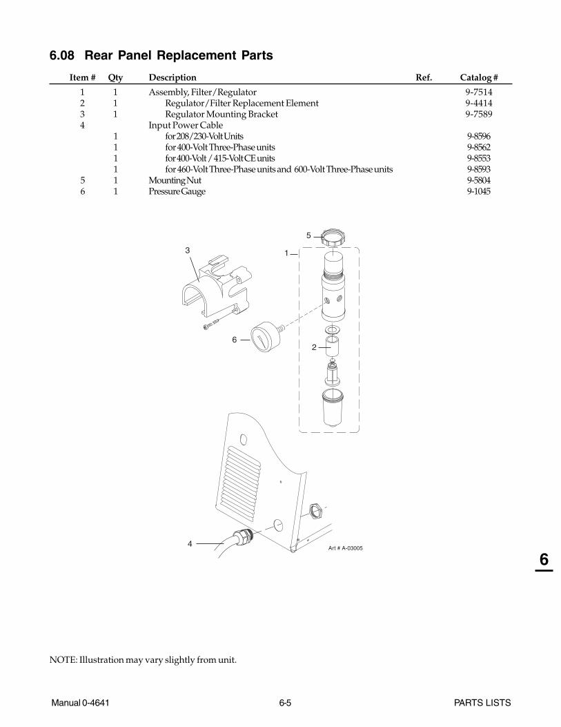
Manual 0-4641 6-5 PARTS LISTS
6
6.08 Rear Panel Replacement Parts
Item # Qty Description Ref. Catalog #
1 1 Assembly, Filter/Regulator 9-75142 1 Regulator/Filter Replacement Element 9-44143 1 Regulator Mounting Bracket 9-75894 Input Power Cable
1 for 208/230-Volt Units 9-85961 for 400-Volt Three-Phase units 9-85621 for 400-Volt / 415-Volt CE units 9-85531 for 460-Volt Three-Phase units and 600-Volt Three-Phase units 9-8593
5 1 Mounting Nut 9-58046 1 Pressure Gauge 9-1045
NOTE: Illustration may vary slightly from unit.
Art # A-03005
2
13
4
5
6

PARTS LISTS 6-6 Manual 0-4641
6
6.09 Power Supply Left Side Internal Replacement Parts
Item # Qty Description Ref # Catalog #
1 1 Fuse F1for 208/230-Volt Power Supplies 9-8588for 400 / 415-Volt Power Supplies 9-8602for 460-Volt Power Supplies 9-8583for 600-Volt Power Supplies 9-8638
Main Input Contactor W12A for 208/230-Volt Power Supplies 9-85872 for 400-Volt, 415-Volt, 460-Volt and 600-Volt Power Supplies 9-85543 1 Connector PC Board 9-85764 1 PC Board Assembly, Logic 9-79925 1 PC Board Assembly Kit, IGBT Circuit
for 208/230-Volt, 400-Volt, 415-Volt, and 460-Volt Power Supplies 9-8578IGBT PC BoardRound Thermal Pad
for 600-Volt Power Supplies 9-8646IGBT PC BoardRound Thermal Pad
6 1 PC Board Assembly Kit, Input Diode 9-7088Input Diode PC BoardRectangular Thermal Pad
7 1 PC Board Assembly, Main Powerfor 208/230-Volt Power Supplies 9-7986for 400-Volt Power Supplies 9-7990for 415-Volt Power Supplies 9-8669for 460-Volt Power Supplies 9-7989for 600-Volt Power Supplies 9-7991
8 1 EMI Filter (for CE Power Supplies only) 9-7667
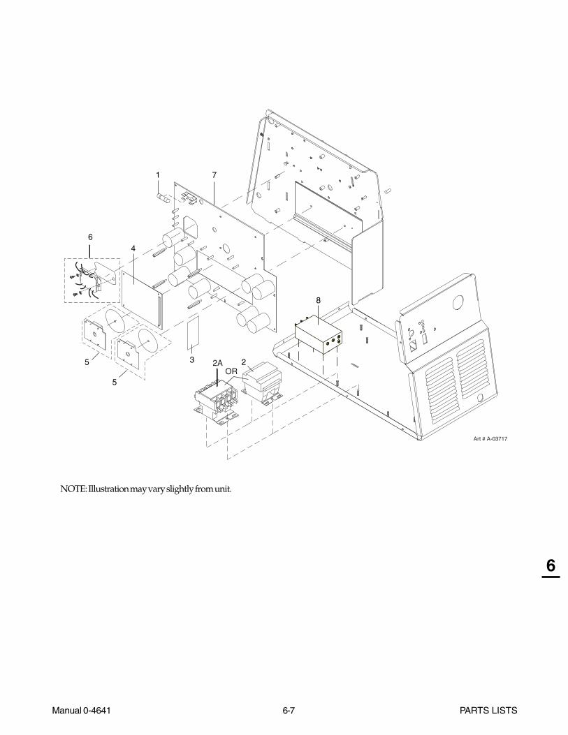
Manual 0-4641 6-7 PARTS LISTS
6
NOTE: Illustration may vary slightly from unit.
3
5
4
1 7
5
Art # A-03717
6
22AOR
8

PARTS LISTS 6-8 Manual 0-4641
6
6.10 Right Side Internal Replacement Parts
Item # Qty Description Ref #. Catalog #
1 1 Assembly, Pressure Switch/Solenoid Sol1, Ps1 9-83292 1 Assembly, Pilot Board 9-79853 1 Fan, 220V, 115 CFM M1, M2 9-76874 1 Assembly, Main Transformer T5
for 208/230-Volt units 9-8589for 400-Volt / 415-Volt units 9-8603for 460-Volt units 9-8584for 600-Volt units 9-8635
5 1 Assembly, Output Inductor L1 9-85916 1 Assembly, Output Power PC Board 9-79887 1 Assembly, Output Diode PC Board 9-8580
1 Round Thermal Pad8 1 Automation Interface PC Board 9-48949 1 Automation Interface Wire Harness 9-4895
10 1 Transformer (only in power supplies connected to SL100SV Torch 9-9449(with solenoid on mounting tube)
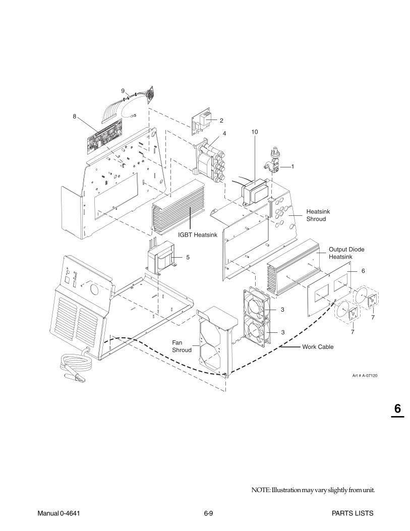
Manual 0-4641 6-9 PARTS LISTS
6
NOTE: Illustration may vary slightly from unit.
2
3
5
1
7
4
6
Art # A-07120
Work Cable
Output DiodeHeatsink
IGBT Heatsink
HeatsinkShroud
FanShroud
3
7
8
8 7 6 5 4 3 2 1
8 7 6 5 4 3 2 1
9
10

PARTS LISTS 6-10 Manual 0-4641
6
6.11 Torch Replacement Parts
SL100 Torch
Item No. Qty Description Catalog No.
1 1 Torch Head Assembly without leads (includes items 2, 3, and 14) 9-8220
2 1 Large O - Ring 8-3487
3 1 Small O - Ring 8-3486
4 1 PIP Switch Kit 9-7036
5 1 PIP Plunger and Return Spring Kit 9-7045
6 Automated Leads Assemblies with ATC connectors
1 5 - foot / 1.5 m Leads Assembly with ATC connector 4-7850
1 10 - foot / 3.05 m Leads Assembly with ATC connector 4-7851
1 25 - foot / 7.6 m Leads Assembly with ATC connector 4-7852
1 50 - foot / 15.2 m Leads Assembly with ATC connector 4-7853
7 1 11" / 279 mm Rack 9-7041
8 1 11" / 279 mm Mounting Tube 9-7043
9 1 End Cap Assembly 9-7044
10 2 Body, Mounting, Pinch Block 9-4513
11 1 Pin, Mounting, Pinch Block 9-4521
12 1 Torch Holder Sleeve 7-2896
13 1 Pinion Assembly (does not include positioning tube) 7-2827
14 1 Torch Holder Sleeve 7-2896
15 1 Pinion Gear-Short 8-6074
16 1 Handwheel (Torch Holder) 9-4514
17 1 Low Profile Torch Holder (1 3/8 Dia) w/o Hardware 9-4515
18 1 Calibrated Torch Holder Bushing 9-4366
19 1 5/32 Dia x 5/8 Lg Slotted Spring Pin See Note 1
20 1 3/8-24 x 3/8 Soc Hd Set Screw, Cup Point See Note 1
21 2 1/4-20 x 5/8 Hex Socket Head Screw See Note 1
22 1 #10-24 x 3/8 Hex Socket Set Screw, Cup Point See Note 1
1 5" / 126 mm Positioning Tube (Not shown) 9-7042
Note 1: Item can be bought locally.

Manual 0-4641 6-11 PARTS LISTS
6
Art # A-03872
6
1
4
2
3
5
8
910
12
11
7
10
22
19
15
14
16
17
18
2021
21
13
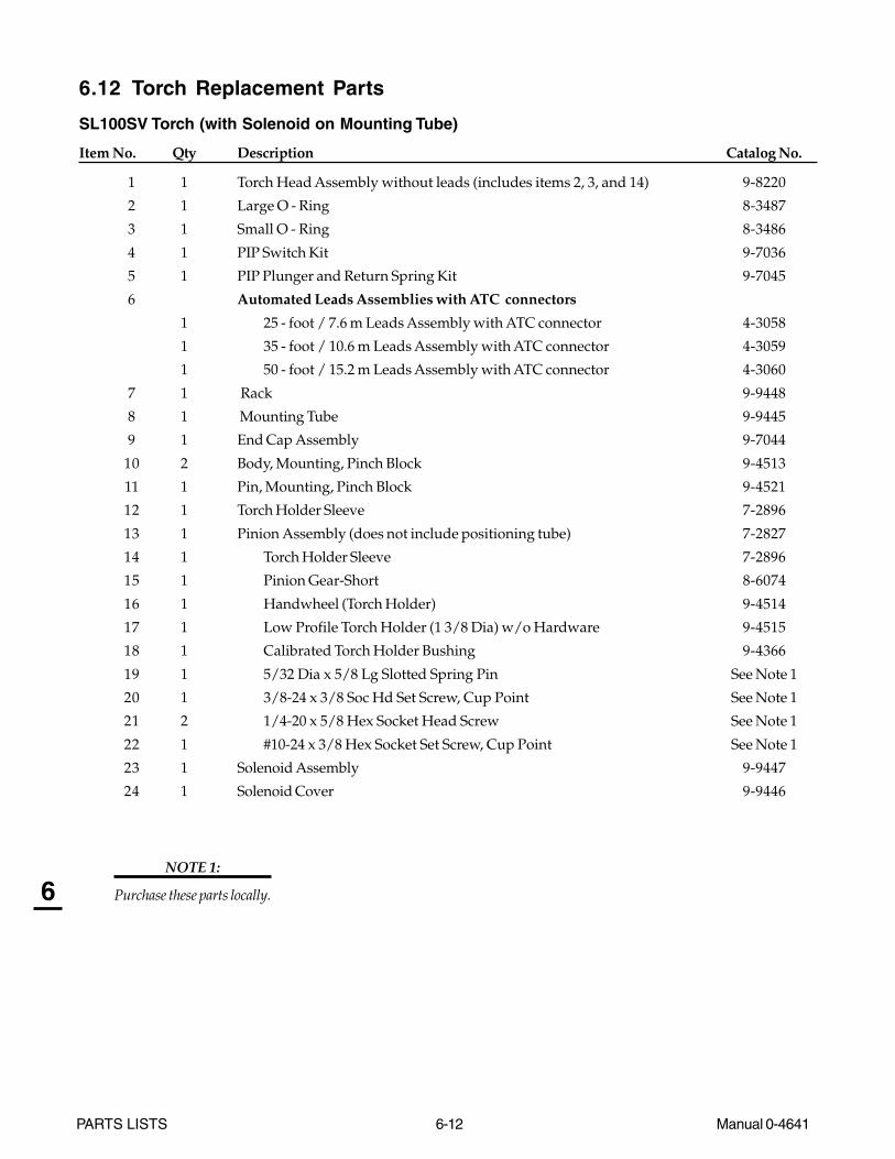
PARTS LISTS 6-12 Manual 0-4641
6
6.12 Torch Replacement Parts
SL100SV Torch (with Solenoid on Mounting Tube)
Item No. Qty Description Catalog No.
1 1 Torch Head Assembly without leads (includes items 2, 3, and 14) 9-8220
2 1 Large O - Ring 8-3487
3 1 Small O - Ring 8-3486
4 1 PIP Switch Kit 9-7036
5 1 PIP Plunger and Return Spring Kit 9-7045
6 Automated Leads Assemblies with ATC connectors
1 25 - foot / 7.6 m Leads Assembly with ATC connector 4-3058
1 35 - foot / 10.6 m Leads Assembly with ATC connector 4-3059
1 50 - foot / 15.2 m Leads Assembly with ATC connector 4-3060
7 1 Rack 9-9448
8 1 Mounting Tube 9-9445
9 1 End Cap Assembly 9-7044
10 2 Body, Mounting, Pinch Block 9-4513
11 1 Pin, Mounting, Pinch Block 9-4521
12 1 Torch Holder Sleeve 7-2896
13 1 Pinion Assembly (does not include positioning tube) 7-2827
14 1 Torch Holder Sleeve 7-2896
15 1 Pinion Gear-Short 8-6074
16 1 Handwheel (Torch Holder) 9-4514
17 1 Low Profile Torch Holder (1 3/8 Dia) w/o Hardware 9-4515
18 1 Calibrated Torch Holder Bushing 9-4366
19 1 5/32 Dia x 5/8 Lg Slotted Spring Pin See Note 1
20 1 3/8-24 x 3/8 Soc Hd Set Screw, Cup Point See Note 1
21 2 1/4-20 x 5/8 Hex Socket Head Screw See Note 1
22 1 #10-24 x 3/8 Hex Socket Set Screw, Cup Point See Note 1
23 1 Solenoid Assembly 9-9447
24 1 Solenoid Cover 9-9446
NOTE 1:
Purchase these parts locally.

Manual 0-4641 6-13 PARTS LISTS
6
Art # A-07113
6
1
4
2
3
5
8
10
12
11
7
10
22
19
15
14
16
17
18
2021
21
13
9
24 23

PARTS LISTS 6-14 Manual 0-4641
6
6.13 Torch Consumables
The illustration shows all SL100 torch consumable parts for use with the CutMaster 81 Automated PowerSupply.
Various front-end torch parts are available for different applications.
The Shield Cup Body with the Deflector Shield Cap provides extended parts life and improved resistance to reflectedheat.
The electrode and start cartridge are the same for all operations.
6.14 Torch Spare Parts Kits
Qty Description Catalog #
40-Amp Automated Machine Torch Spare Parts Kit, includes: 5-00543 Electrode 9-82155 30 Amp Tip 9-82065 40 Amp Standoff Tip 9-82081 Start Cartridge 9-82131 Shield Cup Body 9-82371 Shield Cap, Machine, 40 Amp 9-82451 Shield Cap, Deflector 9-82431 Ohmic Clip Kit 9-82241 Large O - Ring 8-34871 Small O - Ring 8-3486
60-Amp Automated Machine Torch Spare Parts Kit, includes: 5-00791 Start Cartridge 9-82133 Electrode 9-82155 30 Amp Tip 9-82065 40 Amp Standoff Tip 9-82085 40 Amp Standoff Tip 9-82085 60 Amp Standoff Tip 9-82101 Shield Cup Body 9-82371 Shield Cap, Machine, 40 Amp 9-82451 Shield Cap, Machine, 50-60 Amp 9-82381 Shield Cap, Deflector 9-82431 Ohmic Clip Kit 9-82241 Large O - Ring 8-34871 Small O - Ring 8-3486
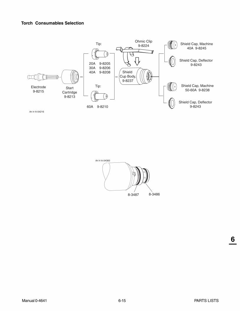
Manual 0-4641 6-15 PARTS LISTS
6
Art # A-04383
8-3487 8-3486
StartCartridge9-8213
Electrode9-8215
Shield Cap, Deflector9-8243
Shield Cap, Machine40A 9-8245
60A 9-8210
Tip:
Shield Cap, Machine50-60A 9-8238
Shield Cap, Deflector9-8243
Shield Cup Body,
9-8237
Tip:
Art # A-04216
20A 9-820530A 9-8206
40A 9-8208
Ohmic Clip9-8224
Torch Consumables Selection
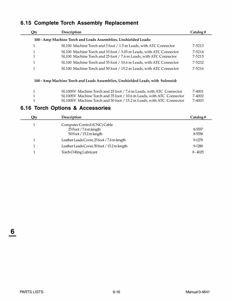
PARTS LISTS 6-16 Manual 0-4641
6
6.15 Complete Torch Assembly Replacement
Qty Description Catalog #
100 - Amp Machine Torch and Leads Assemblies, Unshielded Leads:
1 SL100 Machine Torch and 5 foot / 1.5 m Leads, with ATC Connector 7-5213
1 SL100 Machine Torch and 10 foot / 3.05 m Leads, with ATC Connector 7-52141 SL100 Machine Torch and 25 foot / 7.6 m Leads, with ATC Connector 7-5215
1 SL100 Machine Torch and 35 foot / 10.6 m Leads, with ATC Connector 7-5232
1 SL100 Machine Torch and 50 foot / 15.2 m Leads, with ATC Connector 7-5216
100 - Amp Machine Torch and Leads Assemblies, Unshielded Leads, with Solenoid:
1 SL100SV Machine Torch and 25 foot / 7.6 m Leads, with ATC Connector 7-40011 SL100SV Machine Torch and 35 foot / 10.6 m Leads, with ATC Connector 7-40021 SL100SV Machine Torch and 50 foot / 15.2 m Leads, with ATC Connector 7-4003
6.16 Torch Options & Accessories
Qty Description Catalog #
1 Computer Control (CNC) Cable25 Foot / 7.6 m length 8-555750 Foot / 15.2 m length 8-5558
1 Leather Leads Cover, 25 foot / 7.6 m length 9-1270
1 Leather Leads Cover, 50 foot / 15.2 m length 9-1280
1 Torch O-Ring Lubricant 8 - 4025

Manual 0-4641 6-17 PARTS LISTS
6
PATENT INFORMATION
The following parts are licensed under U.S. Patent No(s). 5120930 and 5132512
Catalog Number Description
9-8235 Shield Cap, Drag 50-60A9-8236 Sheild Cap, Drag 70-100A9-8237 Shield Cup, Body9-8238 Shield Cap, Machine 50-60A9-8239 Shield Cap, Machine 70-100A9-8244 Shield Cap, Drag 40A9-8245 Shield Cap, Machine 40A

PARTS LISTS 6-18 Manual 0-4641
6
This Page Left Blank
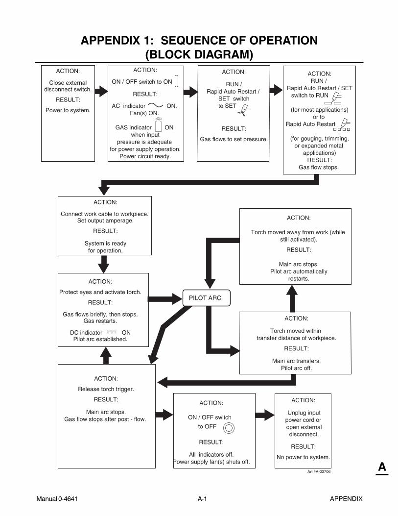
Manual 0-4641 A-1 APPENDIX
A
APPENDIX 1: SEQUENCE OF OPERATION(BLOCK DIAGRAM)
ACTION:
ON / OFF switch to ON
RESULT:
AC indicator ON. Fan(s) ON.
GAS indicator ON
when inputpressure is adequate
for power supply operation.Power circuit ready.
ACTION:
Protect eyes and activate torch.
RESULT:
Gas flows briefly, then stops.Gas restarts.
DC indicator ONPilot arc established.
Art #A-03706
ACTION:
Unplug inputpower cord or open externaldisconnect.
RESULT:
No power to system.
ACTION:
Connect work cable to workpiece. Set output amperage.
RESULT:
System is readyfor operation.
ACTION:
RUN / Rapid Auto Restart /
SET switch to SET
RESULT:
Gas flows to set pressure.
ACTION:RUN /
Rapid Auto Restart / SETswitch to RUN
(for most applications) or to
Rapid Auto Restart
(for gouging, trimming,or expanded metal
applications)RESULT:
Gas flow stops.
ACTION:
Release torch trigger.
RESULT:
Main arc stops.Gas flow stops after post - flow.
ACTION:
ON / OFF switch
to OFF
RESULT:
All indicators off.Power supply fan(s) shuts off.
ACTION:
Close externaldisconnect switch.
RESULT:
Power to system.
ACTION:
Torch moved within transfer distance of workpiece.
RESULT:
Main arc transfers.Pilot arc off.
PILOT ARC
ACTION:
Torch moved away from work (while still activated).
RESULT:
Main arc stops.Pilot arc automatically
restarts.
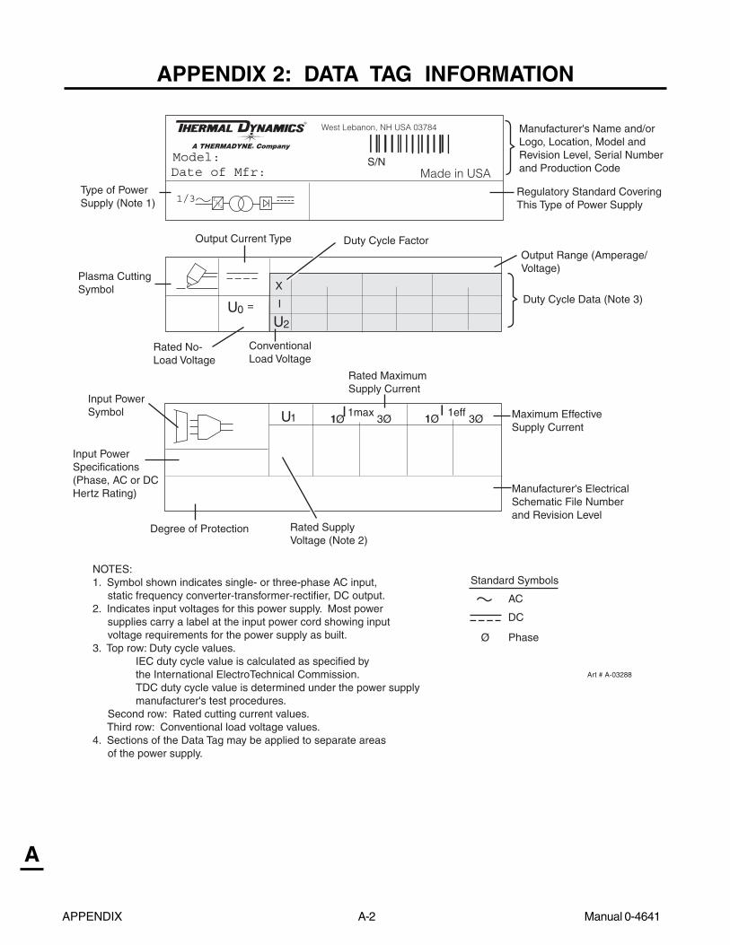
APPENDIX A-2 Manual 0-4641
A
APPENDIX 2: DATA TAG INFORMATION
1/3 ff12
West Lebanon, NH USA 03784
Made in USAModel:
U1 1 11max 1effI I
U2
3Ø 3Ø1Ø1Ø
S/N
U0 =
X
Standard Symbols
Ø
AC
DC
Phase
NOTES:1. Symbol shown indicates single- or three-phase AC input, static frequency converter-transformer-rectifier, DC output.2. Indicates input voltages for this power supply. Most power supplies carry a label at the input power cord showing input voltage requirements for the power supply as built. 3. Top row: Duty cycle values. IEC duty cycle value is calculated as specified by the International ElectroTechnical Commission. TDC duty cycle value is determined under the power supply manufacturer's test procedures. Second row: Rated cutting current values. Third row: Conventional load voltage values.4. Sections of the Data Tag may be applied to separate areas of the power supply.
I
Art # A-03288
Date of Mfr:
Output Range (Amperage/Voltage)
Type of PowerSupply (Note 1)
Output Current Type
Rated No-Load Voltage
Plasma Cutting Symbol
Manufacturer's Name and/orLogo, Location, Model andRevision Level, Serial Number and Production Code
ConventionalLoad Voltage
Regulatory Standard CoveringThis Type of Power Supply
Duty Cycle Data (Note 3)
Duty Cycle Factor
Input PowerSpecifications (Phase, AC or DCHertz Rating)
Input PowerSymbol
Rated Supply Voltage (Note 2)
Rated MaximumSupply Current
Maximum Effective Supply Current
Degree of Protection
Manufacturer's ElectricalSchematic File Numberand Revision Level

Manual 0-4641 A-3 APPENDIX
A
APPENDIX 3: MAINTENANCE SCHEDULE
This schedule applies to all types of non-liquid cooled plasma cutting systems. Some systems will not have all the partslisted and those checks need not be performed.
NOTE
The actual frequency of maintenance may need to be adjusted according to the operating environment.
Daily Operational Checks or Every Six Cutting Hours:
1. Check torch consumable parts, replace if damaged or worn.
2. Inspect torch for any cracks or exposed wires, replace if necessary.
3. Check plasma and secondary supply and pressure/flow.
4. Purge plasma gas line to remove any moisture build-up.
5. Inspect input power cable for damage or exposed wires, replace if necessary.
Weekly or Every 30 Cutting Hours:
1. Check fan for proper operation and adequate air flow.
2. Blow or vacuum dust and dirt out of the entire machine.
CAUTION
Do not blow air into the power supply during cleaning. Blowing air into the unit can cause metal particles to interferewith sensitive electrical components and cause damage to the unit.
Six Months or Every 720 Cutting Hours:
1. Check the in-line air filter(s), clean or replace as required
2. Check cables and hoses for leaks or cracks, replace if necessary.
3. Check all contactor points for severe arcing or pits, replace if necessary.

APPENDIX A-4 Manual 0-4641
A
APPENDIX 4: TORCH PIN - OUT DIAGRAMS
A. Power Supply and SL100 Torch (without Solenoid)
ATC Female Receptacle - Front View
ATC Male Connector - Front View
Negative / Plasma
Pilot
Negative / Plasma
6 - Open
7 - Open
5 - Open
8 - Open8 - Open
5 - White /Not Used
7 - Green /Not Used
56
78
12
3
4
Pilot
12
34
56
78
3 - Open
2 - Orange /PIP
1 - Black /PIP
4- Open
2 - PIP Circuit
1 - PIP Circuit
3 - Not Used
4 - Not Used
6 - Open
Art # A-03900
ATC Female Receptacle - Front View
ATC Male Connector - Front View
Negative / Plasma
Pilot
Negative / Plasma
6 - Open
7 - TorchSolenoid
5 - TorchSolenoid
8 - Open8 - Open
5 - White /- TorchSolenoid
7 - Green /- TorchSolenoid
56
78
12
3
4
Pilot
12
34
56
78
3 - Open
2 - Orange /PIP
1 - Black /PIP
4- Open
2 - PIP Circuit
1 - PIP Circuit
3 - Not Used
4 - Not Used
6 - Open
Art # A-07114
B. Power Supply and SL100SV Torch (with Solenoid)
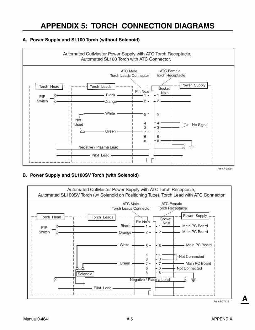
Manual 0-4641 A-5 APPENDIX
A
APPENDIX 5: TORCH CONNECTION DIAGRAMS
A. Power Supply and SL100 Torch (without Solenoid)
Automated CutMaster Power Supply with ATC Torch Receptacle,Automated SL100 Torch with ATC Connector,
Power Supply
PIPSwitch
Not Used
ATC Male Torch Leads Connector
ATC Female Torch Receptacle
Black
Orange
Green
White
Negative / Plasma Lead
Pilot Lead
Art # A-03901
Pin No.sSocket
No.s1
2
5
43768
Torch LeadsTorch Head
No Signal
1
2
5
43768
Automated CutMaster Power Supply with ATC Torch Receptacle,Automated SL100SV Torch (w/ Solenoid on Positioning Tube), Torch Lead with ATC Connector
Power Supply
PIPSwitch
ATC Male Torch Leads Connector
ATC Female Torch Receptacle
Negative / Plasma Lead
Pilot Lead
Art # A-07115
Pin No.sSocket
No.s1
2
5
43768
Main PC Board
1
2
5
43768
White
Black
Orange
Green Main PC Board
Solenoid
Torch LeadsTorch Head
Not Connected
Not Connected
Main PC Board
Main PC Board
B. Power Supply and SL100SV Torch (with Solenoid)
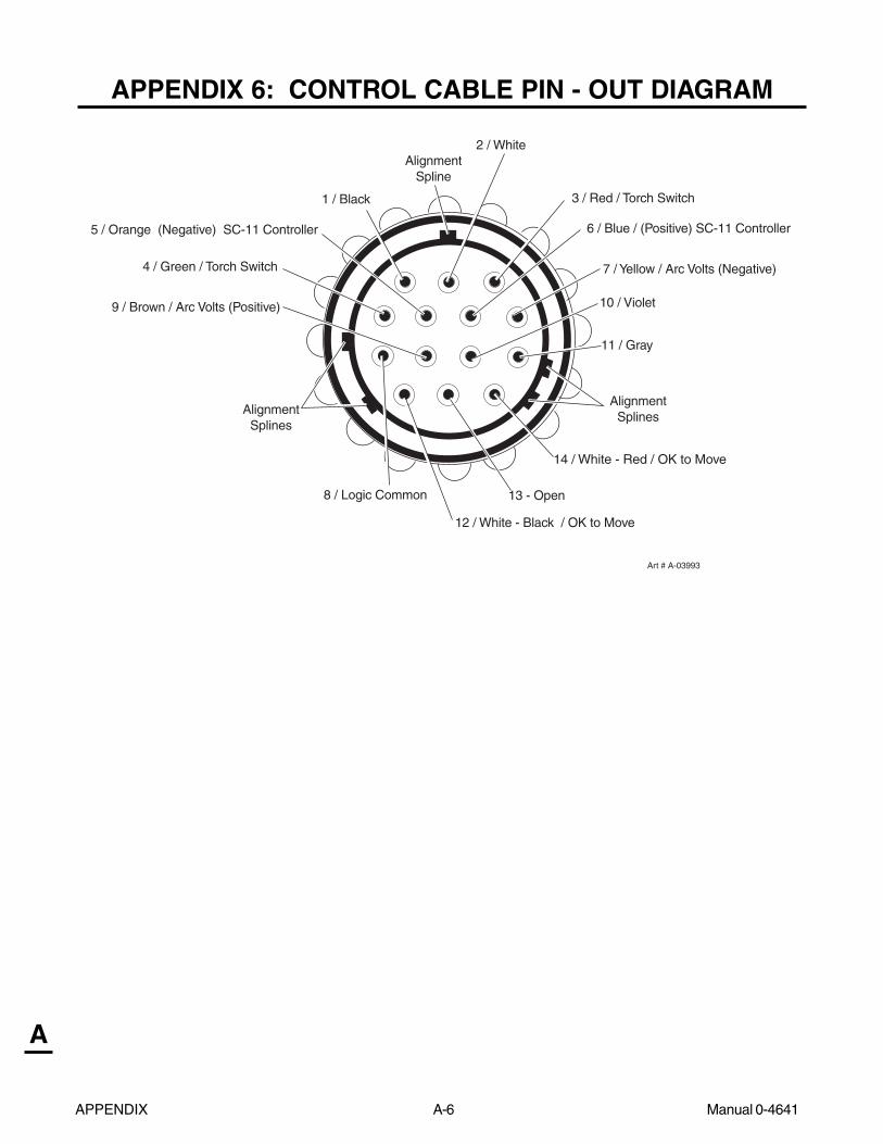
APPENDIX A-6 Manual 0-4641
A
APPENDIX 6: CONTROL CABLE PIN - OUT DIAGRAM
1 / Black
12 / White - Black / OK to Move
6 / Blue / (Positive) SC-11 Controller
7 / Yellow / Arc Volts (Negative)
11 / Gray
10 / Violet
AlignmentSplines
5 / Orange (Negative) SC-11 Controller
4 / Green / Torch Switch
8 / Logic Common
9 / Brown / Arc Volts (Positive)
AlignmentSplines
Art # A-03993
2 / White
13 - Open
14 / White - Red / OK to Move
AlignmentSpline
3 / Red / Torch Switch
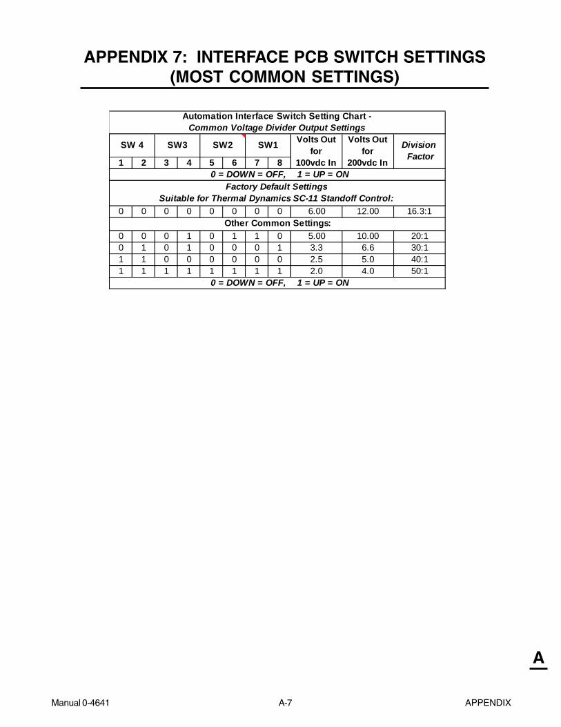
Manual 0-4641 A-7 APPENDIX
A
APPENDIX 7: INTERFACE PCB SWITCH SETTINGS(MOST COMMON SETTINGS)
1 2 3 4 5 6 7 8
0 0 0 0 0 0 0 0 6.00 12.00 16.3:1
0 0 0 1 0 1 1 0 5.00 10.00 20:10 1 0 1 0 0 0 1 3.3 6.6 30:11 1 0 0 0 0 0 0 2.5 5.0 40:11 1 1 1 1 1 1 1 2.0 4.0 50:1
0 = DOWN = OFF, 1 = UP = ON
Automation Interface Switch Setting Chart - Common Voltage Divider Output Settings
0 = DOWN = OFF, 1 = UP = ON
SW 4 SW3 SW2 SW1 Volts Outfor
100vdc In
Volts Outfor
200vdc In
Division Factor
Factory Default Settings Suitable for Thermal Dynamics SC-11 Standoff Control:
Other Common Settings:

APPENDIX A-8 Manual 0-4641
A
Switch 1 Switch 2 Switch 3 Switch 4 Switch 5 Switch 6 Switch 7 Switch 8 Divide Factor
0 0 0 0 0 0 0 0 16.560 0 0 0 0 0 0 1 16.700 0 0 0 0 0 1 0 16.840 0 0 0 0 0 1 1 16.980 0 0 0 0 1 0 0 17.140 0 0 0 0 1 0 1 17.280 0 0 0 0 1 1 0 17.420 0 0 0 0 1 1 1 17.560 0 0 0 1 0 0 0 17.740 0 0 0 1 0 0 1 17.890 0 0 0 1 0 1 0 18.030 0 0 0 1 0 1 1 18.170 0 0 0 1 1 0 0 18.320 0 0 0 1 1 0 1 18.460 0 0 0 1 1 1 0 18.600 0 0 0 1 1 1 1 18.750 0 0 1 0 0 0 0 19.110 0 0 1 0 0 0 1 19.250 0 0 1 0 0 1 0 19.390 0 0 1 0 0 1 1 19.530 0 0 1 0 1 0 0 19.690 0 0 1 0 1 0 1 19.830 0 0 1 0 1 1 0 19.970 0 0 1 0 1 1 1 20.110 0 0 1 1 0 0 0 20.290 0 0 1 1 0 0 1 20.440 0 0 1 1 0 1 0 20.580 0 0 1 1 0 1 1 20.720 0 0 1 1 1 0 0 20.870 0 0 1 1 1 0 1 21.010 0 0 1 1 1 1 0 21.150 0 0 1 1 1 1 1 21.300 0 1 0 0 0 0 0 21.670 0 1 0 0 0 0 1 21.810 0 1 0 0 0 1 0 21.950 0 1 0 0 0 1 1 22.090 0 1 0 0 1 0 0 22.250 0 1 0 0 1 0 1 22.390 0 1 0 0 1 1 0 22.530 0 1 0 0 1 1 1 22.670 0 1 0 1 0 0 0 22.850 0 1 0 1 0 0 1 23.000 0 1 0 1 0 1 0 23.140 0 1 0 1 0 1 1 23.280 0 1 0 1 1 0 0 23.430 0 1 0 1 1 0 1 23.570 0 1 0 1 1 1 0 23.710 0 1 0 1 1 1 1 23.86
Automation Interface Switch Setting Chart - Division Factors 16 - 24
0 = DOWN = OFF, 1 = UP = ON
0 = DOWN = OFF, 1 = UP = ON
APPENDIX 8: INTERFACE PCB SWITCH SETTINGS(Division Factors 16-24)

Manual 0-4641 A-9 APPENDIX
A
APPENDIX 9: INTERFACE PCB SWITCH SETTINGS(Division Factors 24-30)
Switch 1 Switch 2 Switch 3 Switch 4 Switch 5 Switch 6 Switch 7 Switch 8 Divide Factor
0 0 1 1 0 0 0 0 24.220 0 1 1 0 0 0 1 24.360 0 1 1 0 0 1 0 24.500 0 1 1 0 0 1 1 24.640 0 1 1 0 1 0 0 24.800 0 1 1 0 1 0 1 24.940 0 1 1 0 1 1 0 25.080 0 1 1 0 1 1 1 25.220 0 1 1 1 0 0 0 25.400 0 1 1 1 0 0 1 25.550 0 1 1 1 0 1 0 25.690 0 1 1 1 0 1 1 25.830 0 1 1 1 1 0 0 25.980 0 1 1 1 1 0 1 26.120 0 1 1 1 1 1 0 26.260 0 1 1 1 1 1 1 26.410 1 0 0 0 0 0 0 27.320 1 0 0 0 0 0 1 27.460 1 0 0 0 0 1 0 27.600 1 0 0 0 0 1 1 27.740 1 0 0 0 1 0 0 27.890 1 0 0 0 1 0 1 28.040 1 0 0 0 1 1 0 28.180 1 0 0 0 1 1 1 28.320 1 0 0 1 0 0 0 28.500 1 0 0 1 0 0 1 28.650 1 0 0 1 0 1 0 28.780 1 0 0 1 0 1 1 28.930 1 0 0 1 1 0 0 29.080 1 0 0 1 1 0 1 29.221 0 0 0 0 0 0 0 29.310 1 0 0 1 1 1 0 29.361 0 0 0 0 0 0 1 29.450 1 0 0 1 1 1 1 29.501 0 0 0 0 0 1 0 29.591 0 0 0 0 0 1 1 29.730 1 0 1 0 0 0 0 29.871 0 0 0 0 1 0 0 29.89
Automation Interface Switch Setting Chart, Division Factors 24-30
0 = DOWN = OFF, 1 = UP = ON
0 = DOWN = OFF, 1 = UP = ON

APPENDIX A-10 Manual 0-4641
A
APPENDIX 10: INTERFACE PCB SWITCH SETTINGS(Division Factors 30-33)
Switch 1 Switch 2 Switch 3 Switch 4 Switch 5 Switch 6 Switch 7 Switch 8 Divide Factor
0 1 0 1 0 0 0 1 30.011 0 0 0 0 1 0 1 30.030 1 0 1 0 0 1 0 30.151 0 0 0 0 1 1 0 30.170 1 0 1 0 0 1 1 30.291 0 0 0 0 1 1 1 30.310 1 0 1 0 1 0 0 30.441 0 0 0 1 0 0 0 30.490 1 0 1 0 1 0 1 30.591 0 0 0 1 0 0 1 30.640 1 0 1 0 1 1 0 30.731 0 0 0 1 0 1 0 30.780 1 0 1 0 1 1 1 30.871 0 0 0 1 0 1 1 30.920 1 0 1 1 0 0 0 31.051 0 0 0 1 1 0 0 31.070 1 0 1 1 0 0 1 31.201 0 0 0 1 1 0 1 31.210 1 0 1 1 0 1 0 31.331 0 0 0 1 1 1 0 31.350 1 0 1 1 0 1 1 31.481 0 0 0 1 1 1 1 31.500 1 0 1 1 1 0 0 31.630 1 0 1 1 1 0 1 31.771 0 0 1 0 0 0 0 31.860 1 0 1 1 1 1 0 31.911 0 0 1 0 0 0 1 32.000 1 0 1 1 1 1 1 32.051 0 0 1 0 0 1 0 32.141 0 0 1 0 0 1 1 32.280 1 1 0 0 0 0 0 32.431 0 0 1 0 1 0 0 32.440 1 1 0 0 0 0 1 32.571 0 0 1 0 1 0 1 32.580 1 1 0 0 0 1 0 32.711 0 0 1 0 1 1 0 32.720 1 1 0 0 0 1 1 32.851 0 0 1 0 1 1 1 32.86
Automation Interface Switch Setting Chart, Division Factors 30-33
0 = DOWN = OFF, 1 = UP = ON
0 = DOWN = OFF, 1 = UP = ON
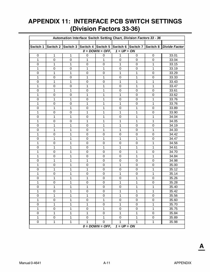
Manual 0-4641 A-11 APPENDIX
A
APPENDIX 11: INTERFACE PCB SWITCH SETTINGS(Division Factors 33-36)
Switch 1 Switch 2 Switch 3 Switch 4 Switch 5 Switch 6 Switch 7 Switch 8 Divide Factor
0 1 1 0 0 1 0 0 33.011 0 0 1 1 0 0 0 33.040 1 1 0 0 1 0 1 33.151 0 0 1 1 0 0 1 33.190 1 1 0 0 1 1 0 33.291 0 0 1 1 0 1 0 33.330 1 1 0 0 1 1 1 33.431 0 0 1 1 0 1 1 33.470 1 1 0 1 0 0 0 33.611 0 0 1 1 1 0 0 33.620 1 1 0 1 0 0 1 33.761 0 0 1 1 1 0 1 33.760 1 1 0 1 0 1 0 33.891 0 0 1 1 1 1 0 33.900 1 1 0 1 0 1 1 34.041 0 0 1 1 1 1 1 34.050 1 1 0 1 1 0 0 34.190 1 1 0 1 1 0 1 34.331 0 1 0 0 0 0 0 34.420 1 1 0 1 1 1 0 34.471 0 1 0 0 0 0 1 34.560 1 1 0 1 1 1 1 34.611 0 1 0 0 0 1 0 34.701 0 1 0 0 0 1 1 34.840 1 1 1 0 0 0 0 34.981 0 1 0 0 1 0 0 35.000 1 1 1 0 0 0 1 35.121 0 1 0 0 1 0 1 35.140 1 1 1 0 0 1 0 35.261 0 1 0 0 1 1 0 35.280 1 1 1 0 0 1 1 35.401 0 1 0 0 1 1 1 35.420 1 1 1 0 1 0 0 35.561 0 1 0 1 0 0 0 35.600 1 1 1 0 1 0 1 35.701 0 1 0 1 0 0 1 35.750 1 1 1 0 1 1 0 35.841 0 1 0 1 0 1 0 35.890 1 1 1 0 1 1 1 35.98
Automation Interface Switch Setting Chart, Division Factors 33 - 36
0 = DOWN = OFF, 1 = UP = ON
0 = DOWN = OFF, 1 = UP = ON
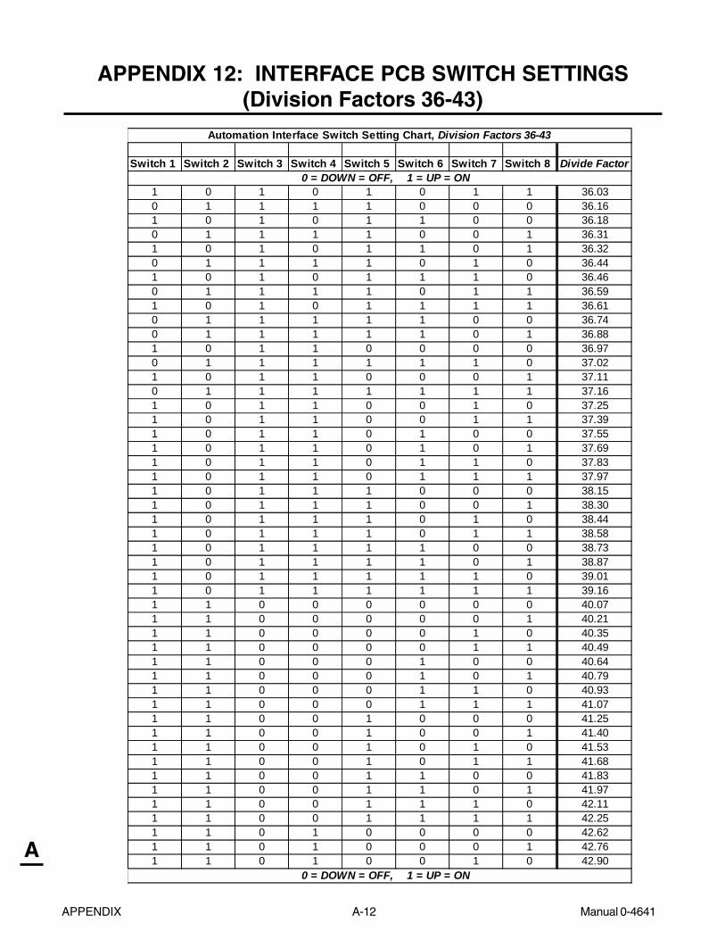
APPENDIX A-12 Manual 0-4641
A
APPENDIX 12: INTERFACE PCB SWITCH SETTINGS(Division Factors 36-43)
Switch 1 Switch 2 Switch 3 Switch 4 Switch 5 Switch 6 Switch 7 Switch 8 Divide Factor
1 0 1 0 1 0 1 1 36.030 1 1 1 1 0 0 0 36.161 0 1 0 1 1 0 0 36.180 1 1 1 1 0 0 1 36.311 0 1 0 1 1 0 1 36.320 1 1 1 1 0 1 0 36.441 0 1 0 1 1 1 0 36.460 1 1 1 1 0 1 1 36.591 0 1 0 1 1 1 1 36.610 1 1 1 1 1 0 0 36.740 1 1 1 1 1 0 1 36.881 0 1 1 0 0 0 0 36.970 1 1 1 1 1 1 0 37.021 0 1 1 0 0 0 1 37.110 1 1 1 1 1 1 1 37.161 0 1 1 0 0 1 0 37.251 0 1 1 0 0 1 1 37.391 0 1 1 0 1 0 0 37.551 0 1 1 0 1 0 1 37.691 0 1 1 0 1 1 0 37.831 0 1 1 0 1 1 1 37.971 0 1 1 1 0 0 0 38.151 0 1 1 1 0 0 1 38.301 0 1 1 1 0 1 0 38.441 0 1 1 1 0 1 1 38.581 0 1 1 1 1 0 0 38.731 0 1 1 1 1 0 1 38.871 0 1 1 1 1 1 0 39.011 0 1 1 1 1 1 1 39.161 1 0 0 0 0 0 0 40.071 1 0 0 0 0 0 1 40.211 1 0 0 0 0 1 0 40.351 1 0 0 0 0 1 1 40.491 1 0 0 0 1 0 0 40.641 1 0 0 0 1 0 1 40.791 1 0 0 0 1 1 0 40.931 1 0 0 0 1 1 1 41.071 1 0 0 1 0 0 0 41.251 1 0 0 1 0 0 1 41.401 1 0 0 1 0 1 0 41.531 1 0 0 1 0 1 1 41.681 1 0 0 1 1 0 0 41.831 1 0 0 1 1 0 1 41.971 1 0 0 1 1 1 0 42.111 1 0 0 1 1 1 1 42.251 1 0 1 0 0 0 0 42.621 1 0 1 0 0 0 1 42.761 1 0 1 0 0 1 0 42.90
Automation Interface Switch Setting Chart, Division Factors 36-43
0 = DOWN = OFF, 1 = UP = ON
0 = DOWN = OFF, 1 = UP = ON

Manual 0-4641 A-13 APPENDIX
A
APPENDIX 13: INTERFACE PCB SWITCH SETTINGS(Division Factors 43-50)
Switch 1 Switch 2 Switch 3 Switch 4 Switch 5 Switch 6 Switch 7 Switch 8 Divide Factor
1 1 0 1 0 0 1 1 43.041 1 0 1 0 1 0 0 43.191 1 0 1 0 1 0 1 43.341 1 0 1 0 1 1 0 43.481 1 0 1 0 1 1 1 43.621 1 0 1 1 0 0 0 43.801 1 0 1 1 0 0 1 43.951 1 0 1 1 0 1 0 44.081 1 0 1 1 0 1 1 44.231 1 0 1 1 1 0 0 44.381 1 0 1 1 1 0 1 44.521 1 0 1 1 1 1 0 44.661 1 0 1 1 1 1 1 44.801 1 1 0 0 0 0 0 45.181 1 1 0 0 0 0 1 45.321 1 1 0 0 0 1 0 45.461 1 1 0 0 0 1 1 45.601 1 1 0 0 1 0 0 45.761 1 1 0 0 1 0 1 45.901 1 1 0 0 1 1 0 46.041 1 1 0 0 1 1 1 46.181 1 1 0 1 0 0 0 46.361 1 1 0 1 0 0 1 46.511 1 1 0 1 0 1 0 46.641 1 1 0 1 0 1 1 46.791 1 1 0 1 1 0 0 46.941 1 1 0 1 1 0 1 47.081 1 1 0 1 1 1 0 47.221 1 1 0 1 1 1 1 47.361 1 1 1 0 0 0 0 47.731 1 1 1 0 0 0 1 47.871 1 1 1 0 0 1 0 48.011 1 1 1 0 0 1 1 48.151 1 1 1 0 1 0 0 48.311 1 1 1 0 1 0 1 48.451 1 1 1 0 1 1 0 48.591 1 1 1 0 1 1 1 48.731 1 1 1 1 0 0 0 48.911 1 1 1 1 0 0 1 49.061 1 1 1 1 0 1 0 49.191 1 1 1 1 0 1 1 49.341 1 1 1 1 1 0 0 49.491 1 1 1 1 1 0 1 49.631 1 1 1 1 1 1 0 49.771 1 1 1 1 1 1 1 49.91
Automation Interface Switch Setting Chart, Division Factors 43 - 50
0 = DOWN = OFF, 1 = UP = ON
0 = DOWN = OFF, 1 = UP = ON

APPENDIX A-14 Manual 0-4641
A
APPENDIX 14: AUTOMATION INTERFACE PC BOARDWIRING LAYOUT
J-1
Automation Interface PC Board
Pilot Board
8 7 6 5 4 3 2 1
321
E1
E3
Art # A-03589
Rear Panel CPC Connector
Automation InterfacePCB Connector J1
INPUTDIODE
E6
E5Main PC Board
Automation InterfacePCB Connector J4
CSR
OutputDiodes
Output Power Board
Hooks for Raw Arc Voltage
To Ground Stud
TS2
TS1
NEG

Manual 0-4641 A-15 APPENDIX
A
APPENDIX 15: AUTOMATION INTERFACE PC BOARDLAYOUT and TEST POINTS
TP1 TP3TP2TP4
Art # A-03903
J1
J4
J2
J3
Signals
Connector J2 (To wiring harness for alternate
CNC Controller)
J2-1 Torch Switch (Positive)J2-2 OpenJ2-3 Torch Switch (Negative)J2-4 OpenJ2-5 OK to MoveJ2-6 OpenJ2-7 OK to MoveJ2-8 OpenJ2-9 Divided Output (Positive)J2-10 OpenJ2-11 Divided Output (Negative)J2-12 OpenJ2-13 Remote Current ControlJ2-14 Remote Current ControlJ2-15 Remote Current ControlJ2-16 OpenJ2-17 DC CommonJ2-18 Arc Volts (+)J2-19 OpenJ2-20 Arc Volts (-)
Connector J4 (to CPC Connector on Power Supply Rear Panel)
J4-1 Arc Volts (-) (Through 100K ohm resistor)J4-2 OpenJ4-3 Arc Volts (+) (Through 100K ohm resistor)J4-4 Logic CommonJ4-5 OpenJ4-6 OpenJ4-7 OpenJ4-8 OpenJ4-9 OpenJ4-10 SC-11 (-)J4-11 OpenJ4-12 SC-11 (+)J4-13 OpenJ4-14 OK to MoveJ4-15 OpenJ4-16 OK to MoveJ4-17 OpenJ4-18 Torch Switch (-)J4-19 OpenJ4-20 Torch Switch (+)

APPENDIX A-16 Manual 0-4641
A
APPENDIX 16: AUTOMATION INTERFACE PC BOARDWIRING CONNECTIONS TO OEM CNC HARNESS
1 2 3 4 5 6 7 8 9 10 11 12 13 14 15 16 17 18 19 20
Art # A-04148
Torc
h Switc
h (P
ositiv
e)
t
o CPC H
ousin
g, P
in 4
Torc
h Switc
h (N
egat
ive)
to C
PC Hou
sing,
Pin
3
OK to M
ove
to
CPC Hou
sing,
Pin
14
OK to M
ove
to C
PC Hou
sing,
Pin
12
Divide
d Out
put (
Positiv
e) t
o CPC H
ousin
g, P
in 6
Divide
d Out
put (
Negat
ive)
to C
PC Hou
sing,
Pin
5
Logic
Com
mon
to C
PC Hou
sing,
Pin
8
Open
Open
Open
Open
Open
Open
Open
Open
Arc Vo
lts (P
ositiv
e) to
CPC H
ousin
g, P
in 9
Arc Vo
lts (
Negat
ive) t
o CPC H
ousin
g, P
in 7
Open
Open
Open
To Main PC Board Terminal J27-3
To Main PC Board Terminal J27-1
To Main PC Board Terminal J27-2
Installed only with Optional Remote Current Control
Terminal Block J4
Automation Interface PC Board
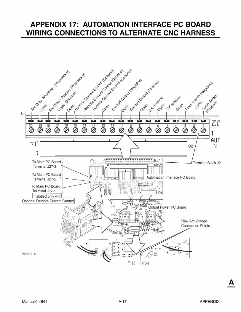
Manual 0-4641 A-17 APPENDIX
A
APPENDIX 17: AUTOMATION INTERFACE PC BOARDWIRING CONNECTIONS TO ALTERNATE CNC HARNESS
39 5 4 12678101319 15 14 111216171820
Art # A-04149
Torc
h Switc
h
(Pos
itive)
Torc
h Switc
h (N
egat
ive)
OK to M
ove
OK to M
ove
Divide
d Out
put (
Positiv
e)
Divide
d Out
put (
Negat
ive)
Logic
Com
mon
Open
Open
Open
Open
Open
Open
Open
Open
Arc V
olts -
Pos
itive
(Pro
priet
ary)
Arc V
olts
Negat
ive -
(Pro
priet
ary)
Remot
e Cur
rent
Con
trol (
Option
al)
Remot
e Cur
rent
Con
trol (
Option
al)
Remot
e Cur
rent
Con
trol (
Option
al)
To Main PC Board Terminal J27-3
To Main PC Board Terminal J27-1
To Main PC Board Terminal J27-2
Installed only with Optional Remote Current Control
Terminal Block J2
E2 (+)E1(-)
Automation Interface PC Board
Output Power PC Board
Raw Arc Voltage Connection Points

APPENDIX A-18 Manual 0-4641
A
APPENDIX 18: MAIN PC BOARD LAYOUT
Art # A-03651
INPUTDIODE
E22
E1
E2
E3
TP1
E7
E15
TP4 U1 J24 J32 J29
E10
E20
E4 J30E33
J18
J26
E27
J23
E30
J33
J31 E23
E32
J27
J25
IGBT A IGBT B
J43
J34
J11
J15
J16
J17
E6
E5
FUSE
Main Power PC Board Signals
J11-1 L1 InputJ11-4 L3 Input
J15-1 Fan (M1)J15-2 Fan (M1)J15-3 Not usedJ15-4 Not usedJ15-5 Fan (M2)J15-6 Fan (M2)
J16-1 Not usedJ16-2 Not used
J17-1 Not usedJ17-2 Not used
J18-1 Not usedJ18-2 Not usedJ18-3 28 VAC BJ18-4 28 VAC AJ18-5 On-Off SwitchJ18-6 On-Off SwitchJ18-7 Run-Set SwitchJ18-8 Run-Set Switch
J23-1 Not usedJ23-2 Not usedJ23-3 Not used
J24-1 Gas Solenoid (SOL1)J24-2 Gas Solenoid (SOL1)J24-3 Pressure Switch (PS1)J24-4 Pressure Switch (PS1)J24-5 Main Contactor (W1)J24-6 Main Contactor (W1)J24-7 Not usedJ24-8 Not used

Manual 0-4641 A-19 APPENDIX
A
J25-1 Gate DriveJ25-2 Gate Drive
J26-1 Gate DriveJ26-2 Gate DriveJ27-1 Pot HighJ27-2 Pot WiperJ27-3 Pot LowJ27-4 +12VJ27-5 ACJ27-6 GasJ27-7 OvertempJ27-8 DC
J29-1 IGBT Heatsink TempJ29-2 IGBT Heatsink TempJ29-3 JumperJ29-4 Jumper
J30-1 Gate DriveJ30-2 Gate Drive
J31-1 Gate DriveJ31-2 Gate Drive
J32-1 Inductor Temp SwitchJ32-2 Inductor Temp Switch
J33-1 - Out SenseJ33-2 DC ComJ33-3 Tip SenseJ33-4 + 12 vdcJ33-5 CSRJ33-6 I SenseJ33-7 Not usedJ33-8 Tip voltsJ34-1 PIP ReturnJ34-2 PIPJ34-3 Not usedJ34-4 Not usedJ34-5 Torch Switch ReturnJ34-6 Torch Switch
J43-1 + 12 vdc to Logic PCBJ43-2 + 12 vdc to Logic PCBJ43-3 DC ComJ43-4 DC ComJ43-5 MC1 OnJ43-6 Tip SenseJ43-7 Run / SetJ43-8 Pressure GoodJ43-9 OvertempJ43-10 CSRJ43-11 Gas onJ43-12 DC OKJ43-13 OVTEMPJ43-14 AC OKJ43-15 Torch SwitchJ43-16 Torch Switch ReturnJ43-17 + 12 vdcJ43-18 POT HighJ43-19 POT WiperJ43-20 POT LowJ43-21 Gate Drive B ReturnJ43-22 Gate Drive BJ43-23 Gate Drive A ReturnJ43-24 Gate Drive AJ43-25 - Out SenseJ43-26 Current SenseJ43-27 Current SenseJ43-28 Current Sense ReturnJ43-29 Current Sense ReturnJ43-30 DC ComJ43-31 DC ComJ43-32 Not UsedJ43-33 I SenseJ43-34 Not UsedJ43-35 Not UsedJ43-36 Tip Volts
TP1 GroundTP4 +12 vdc

APPENDIX A-20 Manual 0-4641
A
APPENDIX 19: MAIN PC BOARD WIRING LAYOUT(208 /230-Volt POWER SUPPLIES)
INPUTDIODE
E2
E3
E1
Art # A-04224
To InputContactor
To Chassis Ground
To Logic Boardvia Connector
To Power Output Board
To TorchConnector
To On/Off andRun/Rapid RestartSet SwitchesTo Fans
To MainInput Contactor
Test Connector To Heat SinkTemp Sensor
Heat SinkTemp Sensor
To Inductor Temp SensorTo Press Switch/Solenoid/Contactor
Fuse
SecondaryTransformer
Copper Strap
#1
To InputContactor
To Auto InterfaceBoard J1-5
To Auto InterfaceBoard J1-6
To MainTransformer
#33
#78#1
LT1
#32
#27
#2
#3
To POT/LED PCB (or to
Optional RemoteCurrent Control )*
* If installed in conjuction with Automation Interface PC Board
J30 J31
Logic Board Not Shown

Manual 0-4641 A-21 APPENDIX
A
APPENDIX 20: MAIN PC BOARD WIRING LAYOUT (400-Volt, 415-Volt, 460-Volt, 600-Volt POWER SUPPLIES)
INPUTDIODE
Art # A-04225
#2#3
#1To InputContactor
To Chassis Ground To Torch
ConnectorTo FansTo MainInput Contactor
TestConnector
Heat SinkTemp Sensor
To Inductor Temp SensorTo Press Switch/Solenoid/Contactor
Fuse
SecondaryTransformer
To MainTransformer
To Logic Boardvia Connector
To Power OutputBoard
To On/Off andRun/Rapid RestartSet Switches
To Heat SinkTemp Sensor
To Auto InterfaceBoard J1-5
To Auto InterfaceBoard J1-6
To POT/LED PCB (or to
Optional RemoteCurrent Control )*
* If installed in conjuction with Automation Interface PC Board
#32
#27
LT1
J30 J31

APPENDIX A-22 Manual 0-4641
A
APPENDIX 21: LOGIC BOARD LAYOUT
TP9
TP10
TP11
TP3
TP7TP8TP5
TP1
TP2
TP4
D13 TP6
Art # A-03654D25
D33
P1-7
P1-9
Logic Board Signals
P1-1 +12vdcfrom Main Power PCBP1-2 +12vdcfrom Main PCBP1-3 DC ComP1-4 DC ComP1-5 MC1 ON signalP1-6 Tip SenseP1-7 RUN/SET Signal Logic Low for SETP1-8 Logic Low = PS1 Pressure Switch
closed = Pressure OKP1-9 Logic Low = TS1 Closed = OVERTEMPP1-10 Logic Low = CSRP1-11 Logic Low = Gas ONP1-12 Logic Low = DC OKP1-13 Logic Low = OVTEMPP1-14 Logic Low = AC OKP1-15 Logic Low = Torch SwitchP1-16 Logic Low = Torch Switch ReturnP1-17 Logic Low = +12vdcP1-18 Logic Low = Pot HighP1-19 Logic Low = Pot HighP1-20 Pot LowP1-21 Gate Drive B ReturnP1-22 Gate Drive BP1-23 Gate Drive A ReturnP1-24 Gate Drive AP1-25 - Out SenseP1-26 Current Sense
P1-27 Current SenseP1-28 Current Sense ReturnP1-29 Current Sense ReturnP1-30 DC ComP1-31 DC ComP1-32 Not UsedP1-33 I SenseP1-34 Not UsedP1-35 Not UsedP1-36 TipVolts
INDICATORS:D13 INV OND25 DRAG OND33 SWITCH ON
TEST POINTS:TP-1 CommonTP-2 Current Demand SignalTP-3 Converter EnableTP-4 CSR (Logic Low)TP-5 Not usedTP-6 Fault (Logic Low)TP-7 DC OK (Logic Low)TP-8 Tip SenseTP-9 Current SenseTP-10 Gate Drive ATP-11 Gate Drive B

Manual 0-4641 A-23 APPENDIX
A
APPENDIX 22: POT / LED BOARD LAYOUT
J14
D4
D5
D7
D6
A-03712
Pot/LED PC Board Signals
J14-1 from Main PC Board (J27-1) Pot HighJ14-2 Main PC Board (J27-2) Pot WiperJ14-3 from Main PC Board (J27-3) Pot LowJ14-4 12vdc (J27-4)J14-5 Logic Low Signal for AC OK Indicator from Logic PC Board (J27-5)J14-6 Logic Low Signal for GAS Indicator from Logic PC Board (J27-6)J14-7 Logic Low Signal for TEMP Indicator from Logic PC Board (J27-7)J14-8 Logic Low Signal for DC Indicator from Logic PC Board (J27-8)
D4 Front Panel AC IndicatorD5 Front Panel TEMP IndicatorD6 Front Panel GAS IndicatorD7 Front Panel DC Indicator

APPENDIX A-24 Manual 0-4641
A
APPENDIX 23: OUTPUT BOARD WIRING DIAGRAM
Art # A-04382
E36
OutputDiode A
OutputDiode B
E32
To Output Inductor
E45
E49
E61
Work Cable
E57E58E43 To OutputInductor
E52
E35 E62
To Torch To Pilot PCB To Main PCB To Pilot PCB
J39 J40E37Chassis Ground
To Trans-former
To Trans-former
TP1
To Torch
E64
To PilotBoard
E47
Raw Arc Voltage Connections
E1 (-) E2 (+)

Manual 0-4641 A-25 APPENDIX
A
APPENDIX 24: OUTPUT DIODE BOARD LAYOUT
A-03152
E48
E50
E54
E53
E34
E39
E60
E56
Output Diode A Output Diode B
E34
E39
E60
E56
E48
E50
E54
E53
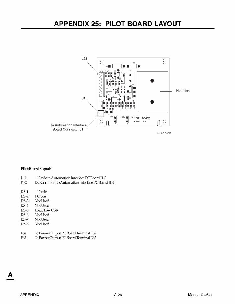
APPENDIX A-26 Manual 0-4641
A
APPENDIX 25: PILOT BOARD LAYOUT
Pilot Board Signals
J1-1 +12 vdc to Automation Interface PC Board J1-3J1-2 DC Common to Automation Interface PC Board J1-2
J28-1 +12 vdcJ28-2 DC ComJ28-3 Not UsedJ28-4 Not UsedJ28-5 Logic Low CSRJ28-6 Not UsedJ28-7 Not UsedJ28-8 Not Used
E58 To Power Output PC Board Terminal E58E62 To Power Output PC Board Terminal E62
J28
Heatsink
To Automation InterfaceBoard Connector J1
Art # A-04218
J1
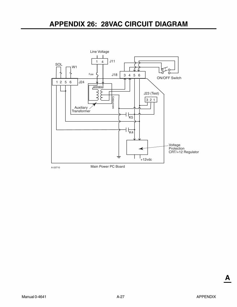
Manual 0-4641 A-27 APPENDIX
A
APPENDIX 26: 28VAC CIRCUIT DIAGRAM
1 2 5 6
3 4 5 6
Main Power PC Board
AuxiliaryTransformer
VoltageProtectionCRT/+12 Regulator
J18
J24
+12vdc
W1SOL
ON/OFF Switch
A-03710
primary
seco
ndar
y
Fuse
23
J23 (Test)
K5
K4
J81 4
Line Voltage
J11
1
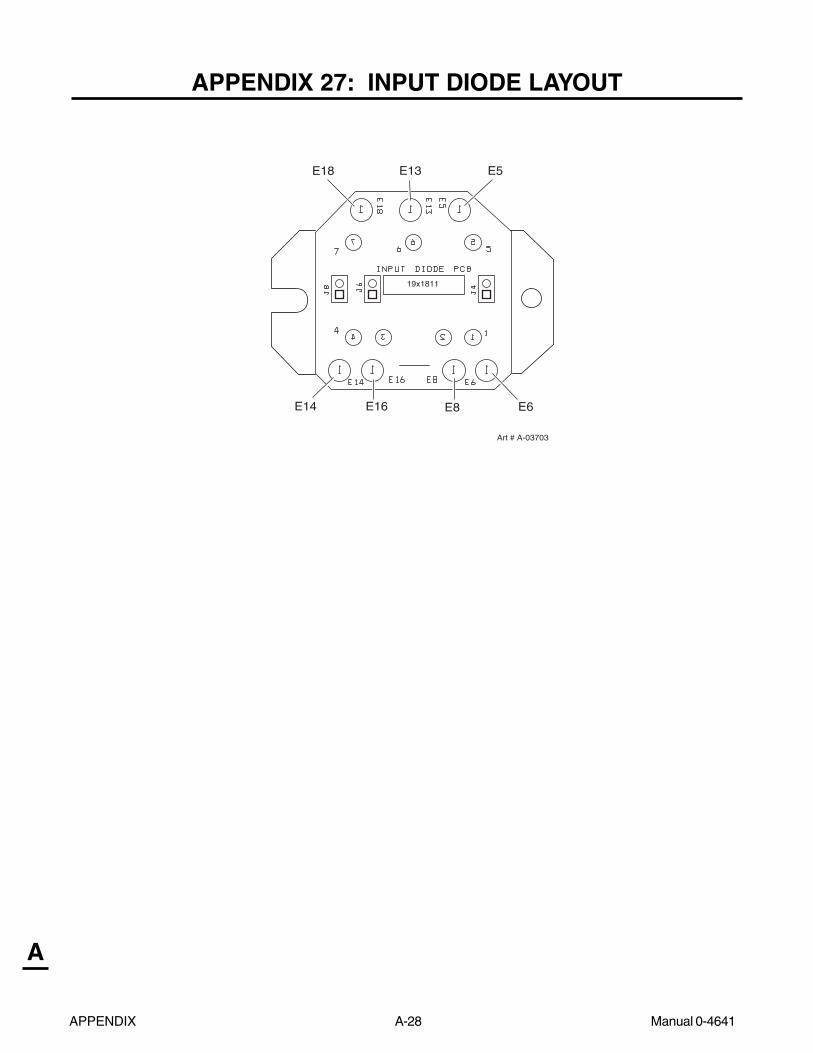
APPENDIX A-28 Manual 0-4641
A
APPENDIX 27: INPUT DIODE LAYOUT
Art # A-03703
E18 E13 E5
E14 E16 E8 E6
19x1811

Manual 0-4641 A-29 APPENDIX
A
This Page Left Blank

APPENDIX A-30 Manual 0-4641
A
APPENDIX 28: 208/230V SYSTEM SCHEMATIC
For Power Supplies and SL100 Torches (without solenoid on mounting tube)
1
1
2
2
3
3
4
4
5
5
A
B
C
D
E
F
+12VDC
+18V
+18V
+18V
208/230V1 PHASEINPUT
2
1
(5)
(3)
2
SE
C
2
2
MAIN BOARDASSY 19X1912
2
ON/OFF SW
CHASSIS GND
1
CURRENTCONTROL/LED PCB19X1604
1
W1
1
(1)
1
(4)
PR
I
(2)
CURRENT ADJUST:20 - 80 FOR CM10120 - 60 FOR CM81
IGBTHEATSINKTEMP
INDUCTORTEMP
P11 J11
INPUT DIODEASSY 19X2073
MAIN TRANSFORMER
J7B
J3B
J7A
J3A
P3B
P7B
P3A
P7A
E22
TESTCONN
GASSOLENOID
PRESSURESWITCH
MAINCONTACTOR
T5
PR
I
SE
C
L1
L2
L3
L4(78)
COPPER STRAP
212223
POT LOWGATE DRIVE B RTN
GATE DRIVE BGATE DRIVE A RTN
GATE DRIVE A- OUT SENSE
CURRENT SENSE
CURRENT SENSE RTN
TIP VOLTS
+12V
TORCH SW
PRESS GOOD
POT WIPER
RUN/SETTIP SENSE
CSR
2425262728293031
ISENSE3233
CURRENT SENSE RTN
343536
CURRENT SENSE
OVERTEMP
OVTEMP
+12VDC
DC OK
45
3
67
12
9
15
10
14
16
13
1920
1718
11
8
12
POT HIGH
+12VDC
AC OK
DC COM
TORCH SW RTN
4
EXTENDER
5
3
67
12
9
15
10
14
16
13
1920
1718
11
8
12
21222324252627282930313233343536
21222324252627282930313233343536
45
3
6
12
9
15
10
14
16
13
1920
1718
11
8
12
D13
7
D33
ASSY 19X1913 - CM101
DC COMW1 ON
D25GAS ON
DC COMDC COM
P13 J12P1
INV ON
DRAG ON
SW ON
ASSY 19X1775
LOGIC
ASSY 19X1932 - CM81
45
3
67
12
9
15
10
14
16
13
1920
1718
11
8
12
21222324252627282930313233343536
TS2
P32 J321
21
2
P29
NTC
1234
1
4
23
J29
TS1
TEMP
AC
P14 P27 J27J14
8
67
4
1
5
23
(36)
(38)(37)
8
65
23
1
4
78
3
5
2
7
1
4
6
(35)
GAS
(41)(40)(39)
(42) 8
67
1
45
23
+12VPOT LOW
OVERTEMP
POT WIPERPOT HIGH
DC
GASAC
DC
(25)(24)
28VAC B
SET
(21)
RUN
(22)28VAC A(23)
SW1
SW2
(26) 8
3
5
2
7
1
4
6
8
67
1
45
23
P18 J18
230V
(6)(6)
(7)230V (7)
3
5
21
4
6 6
1
45
23
FAN1
FAN2
M1
M2
P15 J15
21
34
21
34
W1
W1
W1
P24
W1
PS1
SOL1BA
8
3
5
2
7
1
4
6
J24
8
67
1
45
23
(12)(13)
(11)(10)
(8)(9)
J23
321
3PIP
5
21
4
6 6
1
45
23
TORCH SWTORCH SW RTN
8
PIPPIP RTN
2
TORCH SW
(78)(79)
(80)(81)
J34 P341
43
3
87
2
54
1
6
8
4
76
2
5
1
3DC COM
+12VDC
TIP VOLTS
-OUT SENSE
I SENSE
TIP SENSE
CSR
(71)
(77)
(70)
(73)(74)(75)
(72)
8
2
5
3
1
76
4
76
8
54
1
32
P33J33 J39P39
P26
J25
J30
J31
J26 12
12
12
12 2
P25
P30
P31
21
21
21
1
E5
E13
E18
E6E8
E14E16
E15
E7
E4
E23
E20
E30
E10
E27
E32
GATEDRIVE
GATEDRIVE
GATEDRIVE
GATEDRIVE
E12A
E17A
E19A
E21A
E9A
E11A
E9B
E11B
E19B
E21B
E12B
E17B
IGBT BOARDASSY 19X1756
IGBT BOARDASSY 19X1756
E52 E47
2
1
2
1
2
1
E5E6
(STANDARD)
ATC CONNECTIONCONFIGURATION
(FILTERING)
28VAC B28VAC A
R30
F1T1
K1K1
28VAC A28VAC B
28VAC A
28VAC BGND
TO BIAS SUPPLY
FAN
INRUSH
K1
K2
F2, 0.9A,(RESETABLE)
K4
K5
CONTACTOR ON
K5
SOLENOID ON
K4
PRESS GOOD
8
21
43
ATC RECEIVERATC MALE CONNECTOR
CLOSED WHENPRESSURE OK
(33)
SENSECURRENT
MODE SW
RAR OFF(46)
(6/10A 600V)
(0 ohm)
K2
J43
(PILOT PCB)(F9)
(TS1)(TS2)
E1E1
24
12
23
1314
2527
24567
1
28
24
12
23
1314
2527
24567
1
28
E33E33 E3E3
tt
E2E2
Art # A-06753
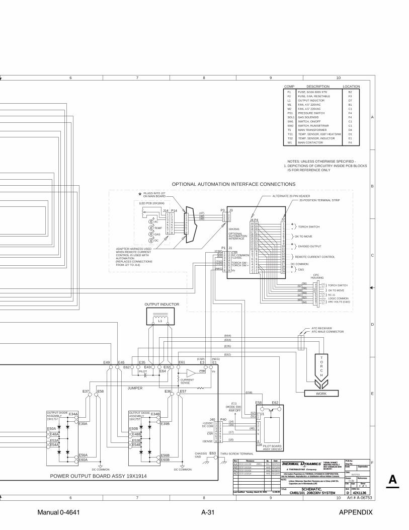
Manual 0-4641 A-31 APPENDIX
A
6
6
7
7
8
8
9
9
10
10
A
B
C
D
E
F
DWG No:
Sheetof
SupersedesScale
Date:
Drawn: References
DateByRevisionsRev PCB No:Assy No:
Information Proprietary to THERMAL DYNAMICS CORPORATION.Not For Release, Reproduction, or Distribution without Written Consent.
NOTE:Unless Otherwise Specified, Resistors are in Ohms 1/4W 5%.Capacitors are in Microfarads (UF) Chk: App:
TITLE:Last Modified:
SizeSCHEMATIC,42X1136Tuesday, March 22, 2005
1 1
INDUSTRIAL PARK No. 2WEST LEBANON, NH 03784603-298-5711
CM81/101 208/230V SYSTEM11:05:29
THERMAL DYNAMICS
DDWG No:
Sheetof
SupersedesScale
Date:
Drawn: References
DateByRevisionsRev PCB No:Assy No:
Information Proprietary to THERMAL DYNAMICS CORPORATION.Not For Release, Reproduction, or Distribution without Written Consent.
NOTE:Unless Otherwise Specified, Resistors are in Ohms 1/4W 5%.Capacitors are in Microfarads (UF) Chk: App:
TITLE:Last Modified:
SizeSCHEMATIC,42X1136Tuesday, March 22, 2005
1 1
INDUSTRIAL PARK No. 2WEST LEBANON, NH 03784603-298-5711
CM81/101 208/230V SYSTEM11:05:29
THERMAL DYNAMICS
D
OUTPUT DIODEASSEMBLY19X1757
THRU SCREW TERMINAL
PILOT
OUTPUT DIODEASSEMBLY19X1757
CHASSISGND
COMP DESCRIPTION LOCATION
D.Lilja
CURRENT
L1
DC COMMON DC COMMON
OUTPUT INDUCTOR
NOTES: UNLESS OTHERWISE SPECIFIED -
IS FOR REFERENCE ONLY
(REL) DLL 05/07/03
SENSE
POWER OUTPUT BOARD ASSY 19X1914
E50AE48A
E53AE54A
E56AE60A
E39A
E34A
E37 E58
DC COM
ISENSE
+12VDCJ40
5
3
76
4
8
21
CSR
1
5
7
3
P40
2
(18)8
4 (17)
(15)(14)
6
(E58)
J28
2
PILOT BOARD
E62
8
1
E58
ASSY 19X2157
5
E49 E45 E35 E61E32
E64E43E62
E36 E57
E63
E34B
E39B
E56BE60B
E50BE48B
E53BE54B
(E62)
(E35)
WORK
TORCH
(E64)(E64)
L1
W1
F1F2
M1M2
TS1TS2
FUSE, 6/10A 600V KTK
MAIN CONTACTOR
OUTPUT INDUCTOR
TEMP. SENSOR, INDUCTORTEMP. SENSOR, IGBT HEATSINKMAIN TRANSFORMER
FAN, 4.5" 220VAC
FUSE, 0.9A, RESETABLE
SWITCH, ON/OFFGAS SOLENOIDPRESSURE SWITCHFAN, 4.5" 220VAC
SWITCH, RUN/SET/RAR
F4
D7B1C1F4F4
C1
E1D1
JUMPER
5897
OK TO MOVE(+)(-)
LOGIC COMMON(+)(-) ARC VOLTS (C&G)
(+)(-) TORCH SWITCH
INTERFACE
Vo
54
6
1
7
23
8
1817
1920
13
10
16
14
9
15
1211
P4
PLUGS INTO J27ON MAIN BOARD*
J2
J1
ALTERNATE 20-PIN HEADER
45
8
23
1
67
20-POSITION TERMINAL STRIP
54
3
54
6
1
7
23
8
67
19
13
10
16
14
9
15
1211
1817
1817
1920
13
10
16
14
9
15
1211
8
21
20
J4
J3
45
23
8
1
67
45
8
32
7
1
OPTIONAL
6
19X2041
TORCH SW -TORCH SW +
DC COMMON+12VDC
CSRP1
OK TO MOVE
+-
AUTOMATION
+-
TORCH SWITCH
SC-11
P3
DC
GAS
AC
TEMP
(LED PCB 19X1604)
J14 P14
7
1
6
32
8
45
1
5
8
4
67
23 3
21 1
23
+-
DC COMMON
DIVIDED OUTPUT
REMOTE CURRENT CONTROL
C&G
CPCHOUSING
4
143
126
1. DEPICTIONS OF CIRCUITRY INSIDE PCB BLOCKS
CSR Vo
E3 E1
}}}
}
C1
D4T5
PS1SOL1
SW2SW1
F3B2
ECO 101136
RAR OFF
3(46)
(47)(48)(49)
(51)(52)
(TS2)(TS1)
(NEG)
(56)(57)
(58)(59)
(60)(61)
(62)(63)
(64)
12
(52)(51)
J1
HAS 02/11/04ECO 101314ABECO 101429 HAS 06/09/04AC
CONTROL IS USED WITHWHEN REMOTE CURRENT
(REPLACES CONNECTIONSAUTOMATION
ADAPTER HARNESS USED
FROM J27 TO J14)
OPTIONAL AUTOMATION INTERFACE CONNECTIONS
05/07/03
ATC MALE CONNECTORATC RECEIVER
(C1)(MODE SW)
(CSR)
(CSR) (NEG)
AA
ECO 101614AD HAS 03/22/05
Art # A-06753

APPENDIX A-32 Manual 0-4641
A
APPENDIX 29: 208/230V SYSTEM SCHEMATIC
For Power Supplies and SL100SV Torches (with solenoid on mounting tube)1
1
2
2
3
3
4
4
5
5
A
B
C
D
E
F
+12VDC
+18V
+18V
+18V
208/230V1 PHASEINPUT
2
1
(5)
(3)
2
SE
C
2
2
MAIN BOARDASSY 19X1912
2
ON/OFF SW
CHASSIS GND
1
CURRENTCONTROL/LED PCB19X1604
1
W1
1
(1)
1
(4)
PR
I
(2)
CURRENT ADJUST:20 - 80 FOR CM10120 - 60 FOR CM81
IGBTHEATSINKTEMP
INDUCTORTEMP
P11
J11
INPUT DIODEASSY 19X2073
MAIN TRANSFORMER
J7B
J3B
J7A
J3A
P3B
P7B
P3A
P7A
E22
TESTCONN
GASSOLENOID
PRESSURESWITCH
MAIN CONTACTOR
T5
PR
I
SE
C
L1
L2
L3
L4(78)
COPPER STRAP
212223
POT LOWGATE DRIVE B RTN
GATE DRIVE BGATE DRIVE A RTN
GATE DRIVE A- OUT SENSE
CURRENT SENSE
CURRENT SENSE RTN
TIP VOLTS
+12V
TORCH SW
PRESS GOOD
POT WIPER
RUN/SETTIP SENSE
CSR
2425262728293031
ISENSE3233
CURRENT SENSE RTN
343536
CURRENT SENSE
OVERTEMP
OVTEMP
+12VDC
DC OK
45
3
67
12
9
15
10
14
16
13
1920
1718
11
8
12
POT HIGH
+12VDC
AC OK
DC COM
TORCH SW RTN
4
EXTENDER
5
3
67
12
9
15
10
14
16
13
1920
1718
11
8
12
21222324252627282930313233343536
21222324252627282930313233343536
45
3
6
12
9
15
10
14
16
13
1920
1718
11
8
12
D13
7
D33
ASSY 19X2285 - CM101
DC COMW1 ON
D25GAS ON
DC COMDC COM
P13 J12P1
INV ON
DRAG ON
SW ON
ASSY 19X1775
ASSY 19X2284 - CM81 45
3
67
12
9
15
10
14
16
13
1920
1718
11
8
12
21222324252627282930313233343536
TS2
P32 J321
21
2
P29
NTC
1234
1
4
23
J29
TS1
TEMP
AC
P14 P27 J27J14
8
67
4
1
5
23
(36)
(38)(37)
8
65
23
1
4
78
3
5
2
7
1
4
6
(35)
GAS
(41)(40)(39)
(42) 8
67
1
45
23
+12VPOT LOW
OVERTEMP
POT WIPERPOT HIGH
DC
GASAC
DC
(25)(24)
28VAC B
SET
(21)
RUN
(22)28VAC A(23)
SW1
SW2
(26) 8
3
5
2
7
1
4
6
8
67
1
45
23
P18 J18
230V
(6)(6)
(7)230V (7)
3
5
21
4
6 6
1
45
23
FAN1
FAN2
M1
M2
P15 J15
21
34
21
34
W1
W1
W1
P24
W1
PS1
SOL1BA
8
3
5
2
7
1
4
6
J24
8
67
1
45
23
(12)(13)
(11)(10)
(8)(9)
J23
321
3PIP
5
21
4
6 6
1
45
23
TORCH SWTORCH SW RTN
8
PIPPIP RTN
2
TORCH SW
(78)(79)
(80)(81)
J34 P341
43
3
87
2
54
1
6
8
4
76
2
5
1
3DC COM
+12VDC
TIP VOLTS
-OUT SENSE
I SENSE
TIP SENSE
CSR
(71)
(77)
(70)
(73)(74)(75)
(72)
8
2
5
3
1
76
4
76
8
54
1
32
P33J33 J39P39
P26
J25
J30
J31
J26 12
12
12
12 2
P25
P30
P31
21
21
21
1
E5
E13
E18
E6E8
E14E16
E15
E7
E4
E23
E20
E30
E10
E27
E32
GATEDRIVE
GATEDRIVE
GATEDRIVE
GATEDRIVE
E12A
E17A
E19A
E21A
E9A
E11A
E9B
E11B
E19B
E21B
E12B
E17B
IGBT BOARDASSY 19X1756
IGBT BOARDASSY 19X1756
E52 E47
2
1
2
1
2
1
E5E6
(STANDARD)
ATC CONNECTIONCONFIGURATION
(FILTERING)
28VAC B28VAC A
R30
F1T1
K1K1
28VAC A28VAC B
28VAC A
28VAC BGND
TO BIAS SUPPLY
FAN
INRUSH
K1
K2
F2, 0.9A,(RESETABLE)
K4
K5
CONTACTOR ON
K5
SOLENOID ON
K4
PRESS GOOD
8
21
43
ATC RECEIVER
ATC MALECONNECTOR
CLOSED WHENPRESSURE OK
(33)
SENSECURRENT
MODE SW
RAR OFF(46)
(6/10A 600V)
(0 ohm)
K2
J43
(PILOT PCB)(F9)
(TS1)(TS2)
SOL2BA T6
11 15
6 10
PRI
SEC
WHEN OPTIONAL TORCH MOUNTED GAS SOLENOID IS USED,SOL1 IS POWERED BY T6 ONLY ,SOL2 POWERED BY P24-1,-2
FACTORY INSTALLED OPTIONAL TORCH MOUNTED GAS SOLENOID
57
57
ASSY 19X1913 - CM101LOGIC
ASSY 19X1932 - CM81
E1E1
24
12
23
1314
2527
24567
1
28
24
12
23
1314
2527
24567
1
28
E33E33 E3E3
tt
E2E2
Art # A-07153

Manual 0-4641 A-33 APPENDIX
A
6
6
7
7
8
8
9
9
10
10
A
B
C
D
E
F
DWG No:
Sheetof
SupersedesScale
Date:
Drawn: References
DateByRevisionsRev PCB No:Assy No:
Information Proprietary to THERMAL DYNAMICS CORPORATION.Not For Release, Reproduction, or Distribution without Written Consent.
NOTE:Unless Otherwise Specified, Resistors are in Ohms 1/4W 5%.Capacitors are in Microfarads (UF) Chk: App:
TITLE:Last Modified:
SizeSCHEMATIC,42X1136Friday, January 27, 2006
1 1
INDUSTRIAL PARK No. 2WEST LEBANON, NH 03784603-298-5711
CM81/101 208/230V SYSTEM11:05:29
THERMAL DYNAMICS
DDWG No:
Sheetof
SupersedesScale
Date:
Drawn: References
DateByRevisionsRev PCB No:Assy No:
Information Proprietary to THERMAL DYNAMICS CORPORATION.Not For Release, Reproduction, or Distribution without Written Consent.
NOTE:Unless Otherwise Specified, Resistors are in Ohms 1/4W 5%.Capacitors are in Microfarads (UF) Chk: App:
TITLE:Last Modified:
SizeSCHEMATIC,42X1136Friday, January 27, 2006
1 1
INDUSTRIAL PARK No. 2WEST LEBANON, NH 03784603-298-5711
CM81/101 208/230V SYSTEM11:05:29
THERMAL DYNAMICS
D
OUTPUT DIODEASSEMBLY19X1757
THRU SCREW TERMINAL
PILOT
OUTPUT DIODEASSEMBLY19X1757
CHASSISGND
COMP DESCRIPTION LOCATION
D.Lilja
CURRENT
L1
NOMMOC CDNOMMOC CD
OUTPUT INDUCTOR
NOTES: UNLESS OTHERWISE SPECIFIED -
IS FOR REFERENCE ONLY
(REL) DLL 05/07/03
SENSE
POWER OUTPUT BOARD ASSY 19X1914
E50AE48A
E53AE54A
E56AE60A
E39A
E34A
E37 E58
DC COM
ISENSE
+12VDCJ40
5
3
76
4
8
21
CSR
1
5
7
3
P40
2
(18)8
4 (17)
(15)(14)
6
(E58)
J28
2
PILOT BOARD
E62
8
1
E58
ASSY 19X2157
5
E49 E45 E35 E61E32
E64E43E62
E36 E57
E63
E34B
E39B
E56BE60B
E50BE48B
E53BE54B
(E62)
(E35)
WORK
TORCH
(E64)(E64)
L1
W1
F1F2
M1M2
TS1TS2
FUSE, 6/10A 600V KTK
MAIN CONTACTOR
OUTPUT INDUCTOR
TEMP. SENSOR, INDUCTORTEMP. SENSOR, IGBT HEATSINKMAIN TRANSFORMER
FAN, 4.5" 220VAC
FUSE, 0.9A, RESETABLE
SWITCH, ON/OFFGAS SOLENOIDPRESSURE SWITCHFAN, 4.5" 220VAC
SWITCH, RUN/SET/RAR
F4
D7B1C1F4F4
C1
E1D1
JUMPER
5897
OK TO MOVE(+)(-)
LOGIC COMMON(+)(-) ARC VOLTS (C&G)
(+)(-) TORCH SWITCH
INTERFACE
Vo
54
6
1
7
23
8
1817
1920
13
10
16
14
9
15
1211
P4
PLUGS INTO J27ON MAIN BOARD*
J2
J1
ALTERNATE 20-PIN HEADER
45
8
23
1
67
20-POSITION TERMINAL STRIP
54
3
54
6
1
7
23
8
67
19
13
10
16
14
9
15
1211
1817
1817
1920
13
10
16
14
9
15
1211
8
21
20
J4J3
45
23
8
1
67
45
8
32
7
1
OPTIONAL
6
19X2041
TORCH SW -TORCH SW +
DC COMMON+12VDC
CSRP1
OK TO MOVE
+-
AUTOMATION
+-
TORCH SWITCH
SC-11
P3
DC
GAS
AC
TEMP
(LED PCB 19X1604)
J14 P14
7
1
6
32
8
45
1
5
8
4
67
23 3
21 1
23
+-
DC COMMON
DIVIDED OUTPUT
REMOTE CURRENT CONTROL
C&G
CPCHOUSING
4
143
126
1. DEPICTIONS OF CIRCUITRY INSIDE PCB BLOCKS
CSR Vo
E3 E1
}}}
}
C1
D4T5
PS1SOL1
SW2SW1
F3B2
ECO 101136
RAR OFF
3(46)
(47)(48)(49)
(51)(52)
(TS2)(TS1)
(NEG)
(56)(57)
(58)(59)
(60)(61)
(62)(63)
(64)
12
(52)(51)
J1
HAS 02/11/04ECO 101314ABECO 101429 HAS 06/09/04AC
CONTROL IS USED WITHWHEN REMOTE CURRENT
(REPLACES CONNECTIONSAUTOMATION
ADAPTER HARNESS USED
FROM J27 TO J14)
OPTIONAL AUTOMATION INTERFACE CONNECTIONS
05/07/03
ATC MALE CONNECTORATC RECEIVER
(C1)(MODE SW)
(CSR)
(CSR) (NEG)
AA
ECO 101614AD HAS 03/22/05AE ECO B028 RS 01/09/06
AF ECO B016 RWH 01/27/06
Art # A-07153

APPENDIX A-34 Manual 0-4641
A
APPENDIX 30: 400 / 415V / 460V SYSTEM SCHEMATIC
For Power Supplies and SL100 Torches (without solenoid on mounting tube)
Art # A-03600
1
1
2
2
3
3
4
4
5
5
A
B
C
D
E
F
+12VDC
+18V
+18V
+18V
415/400
AC
(5)
(3)
2
SE
C
2
GAS
2
DC
ASSY 19X1929 (460V)
GATEDRIVE
2
ON/OFF SW
CHASSIS GND
1
CURRENTCONTROL/LED PCB19X1604
W11
TEMP
W1
1
(1)
1
W1
(4)
PR
I
(2)
CURRENT ADJUST:20 - 80 FOR CM10120 - 60 FOR CM81
IGBTHEATSINKTEMP
INDUCTORTEMP
J29
TS1
J14
P18 J18
FAN1
FAN2
M1
M2
J15P15
1
34
2
P11 J11
BA
INPUT DIODEASSY 19X2073 IGBT BOARD
ASSY 19X1756
MAIN TRANSFORMER
J7B
J3B
J7A
J3A
P3B
P7B
P3A
P7A
E22
TESTCONN
P24
W1
PS1
SOL1 GASSOLENOID
PRESSURESWITCH
MAINCONTACTOR
T5
PR
I
SE
C
P14 J27P27
J33 P33 P39 J39
ATC CONNECTIONCONFIGURATION
(STANDARD)
400V3 PHASEINPUT
GATEDRIVE
GATEDRIVE
GATEDRIVE
11
22
11
22
212223
POT LOWGATE DRIVE B RTN
GATE DRIVE BGATE DRIVE A RTN
GATE DRIVE A- OUT SENSE
CURRENT SENSE
CURRENT SENSE RTN
TIP VOLTS
+12V
TORCH SW
PRESS GOOD
POT WIPER
RUN/SETTIP SENSE
CSR
2425262728293031
ISENSE3233
CURRENT SENSE RTN
343536
CURRENT SENSE
OVERTEMP
OVTEMP
+12VDC
DC OK
45
3
67
12
9
15
10
14
16
13
1920
1718
11
8
12
POT HIGH
+12VDC
AC OK
DC COM
TORCH SW RTN
4
EXTENDER
5
3
67
12
9
15
10
14
16
13
1920
1718
11
8
12
21222324252627282930313233343536
21222324252627282930313233343536
45
3
6
12
9
15
10
14
16
13
1920
1718
11
8
12
45
3
67
12
9
15
10
14
16
D13
13
1920
1718
11
8
12
21222324252627282930313233343536
7
D33
ASSY 19X1913 - CM101
DC COMW1 ON
D25GAS ON
DC COMDC COM
P13 J12 J43P1
INV ON
DRAG ON
SW ON
ASSY 19X1775
LOGIC
ASSY 19X1932 - CM81
8
3
5
2
7
1
4
6
8
67
4
1
5
23
DC COM
TIP VOLTS
+12VDC
I SENSE
-OUT SENSE
CSR
TIP SENSE(71)(70)
(77)
(75)(74)(73)(72)
8
3
5
2
7
1
4
6
8
67
1
45
23
PIP3
5
21
4
6 6
1
45
23
8TORCH SW
TORCH SW RTN
PIPPIP RTN
2
TORCHSW
(78)(79)
(80)(81)
J34 P341
43
J23
321
8
3
5
2
7
1
4
6
J24
8
67
1
45
23
(12)(13)
(11)(10)
(8)(9)
J25
J30
J31
J26 12
12
12
12 2
P25
P30
P31
21
21
21
1
TS2
P32 J321
21
2
P29
NTC
1234
1
4
23
(25)(24)
28VAC B
SET
(21)(22)28VAC A(23)
SW1
SW2
(26) 8
3
5
2
7
1
4
6 28VAC B28VAC A
8
67
1
45
23
230V
(6)(6)
(7)230V (7)
3
5
21
4
6 6
1
45
23
1
34
2400V 'CE' VERSIONINCLUDES IN-LINEEMC FILTER
IGBT BOARDASSY 19X1756
E12A
E17A
E19A
E21A
E9A
E11A
E12B
E17B
E19B
E21B
E9B
E11B
E52 E47
E3E2E1
E5
E13
E18
E6E8
E14E16
E15
E7
E4
E23
E20
E30
P26
E10
E27
E328
67
4
1
5
23
(36)
(38)(37)
8
65
23
1
4
78
3
5
2
7
1
4
6
(35)
(41)(40)(39)
(42) 8
67
1
45
23
+12VPOT LOW
OVERTEMP
POT WIPERPOT HIGH
DC
GASAC
E5E6
(FILTERING)
R29 (415/460/600V)
R78 (400V)
R30 (208/230V)
F1
T1
K2
K1K1
28VAC A28VAC B
28VAC A
28VAC BGND
SEE TABLE 1 FORF1, R29,R30 & R78
CLOSED WHENPRESSURE OK
TO BIAS SUPPLY
FAN
INRUSH
K1
K2
CONTACTOR ON
K5
SOLENOID ON
K4
K5
K4F2, 0.9A,(RESETABLE)
PRESS GOOD
8
21
43
ATC RECEIVER
ATC MALECONNECTOR
SENSECURRENT
MODE SW
RAR OFF
RUN
(46)
L1
L2
L3
E33
(PILOT PCB)(F9)
(TS1)
(TS2)
ARC HOLD
E34E36E35
28VAC A28VAC B
ARC HOLD
INPUT
/4603 PHASE
INPUT1 PHASE208/230V
MAIN BOARDASSY 19X1930 (400V)ASSY 19X2228 (415V)
24
12
23
1314
2527
24567
1
28
24
12
23
1314
2527
24567
1
28
tt
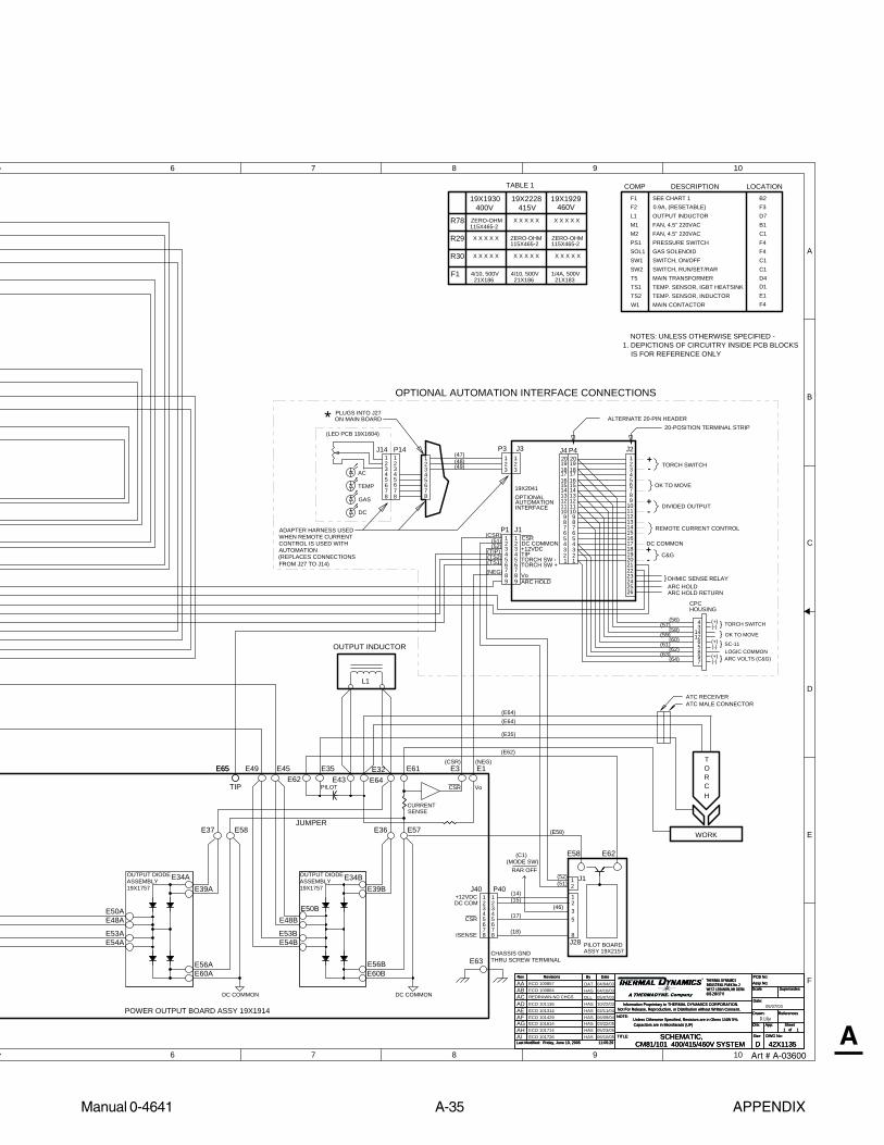
Manual 0-4641 A-35 APPENDIX
AArt # A-03600
6
6
7
7
8
8
9
9
10
10
A
B
C
D
E
F
DWG No:
Sheetof
SupersedesScale
Date:
Drawn: References
DateByRevisionsRev PCB No:Assy No:
Information Proprietary to THERMAL DYNAMICS CORPORATION.Not For Release, Reproduction, or Distribution without Written Consent.
NOTE:Unless Otherwise Specified, Resistors are in Ohms 1/4W 5%.Capacitors are in Microfarads (UF) Chk: App:
TITLE:Last Modified:
SizeSCHEMATIC,42X1135Friday, June 10, 2005
1 1
INDUSTRIAL PARK No. 2WEST LEBANON, NH 03784603-298-5711
CM81/101 400/415/460V SYSTEM11:05:29
THERMAL DYNAMICS
DDWG No:
Sheetof
SupersedesScale
Date:
Drawn: References
DateByRevisionsRev PCB No:Assy No:
Information Proprietary to THERMAL DYNAMICS CORPORATION.Not For Release, Reproduction, or Distribution without Written Consent.
NOTE:Unless Otherwise Specified, Resistors are in Ohms 1/4W 5%.Capacitors are in Microfarads (UF) Chk: App:
TITLE:Last Modified:
SizeSCHEMATIC,42X1135Friday, June 10, 2005
1 1
INDUSTRIAL PARK No. 2WEST LEBANON, NH 03784603-298-5711
CM81/101 400/415/460V SYSTEM11:05:29
THERMAL DYNAMICS
D
OUTPUT DIODEASSEMBLY19X1757
THRU SCREW TERMINAL
PILOT
OUTPUT DIODEASSEMBLY19X1757
(E62)
CHASSIS GND
COMP DESCRIPTION LOCATIONSEE CHART 1
D.Lilja
CURRENT
L1
DC COMMON DC COMMON
OUTPUT INDUCTOR
NOTES: UNLESS OTHERWISE SPECIFIED -1. DEPICTIONS OF CIRCUITRY INSIDE PCB BLOCKS
IS FOR REFERENCE ONLY
REDRAWN-NO CHGS 05/07/03
SENSE
POWER OUTPUT BOARD ASSY 19X1914
04/10/0304/04/03DAT
HASECO 100864ECO 100857
ACAB
W1
L1
F1F2
SW1SW2
M1M2PS1SOL1
T5TS1TS2
MAIN CONTACTOR
TEMP. SENSOR, IGBT HEATSINKTEMP. SENSOR, INDUCTOR
OUTPUT INDUCTOR
MAIN TRANSFORMER
FAN, 4.5" 220VAC
PRESSURE SWITCHGAS SOLENOIDSWITCH, ON/OFFSWITCH, RUN/SET/RAR
FAN, 4.5" 220VAC
F4
D7
B2
B1C1F4F4C1C1D4
E1
F3
D1
1
5
J28
7
23
P40
2
(18)
PILOT BOARD
8
4
E62
(17)
8
1
E58
(15)
ASSY 19X2157
(14)
65
DC COM
ISENSE
+12VDCJ40
5
3
76
4
8
21
CSR
(E35)
WORK
TORCH
(E64)(E64)
DLL
E50BE48B
E53BE54B
E34BE39B
E56BE60B
E36 E57
E49 E45E62
E35E43 E64
E32 E61
E58E37
E50AE48A
E53AE54A
E56AE60A
E34AE39A
E63
(E58)JUMPER
5897
OK TO MOVE(+)(-)
LOGIC COMMON(+)(-) ARC VOLTS (C&G)
(+)(-) TORCH SWITCH
Vo
54
6
1
7
23
8
1817
1920
13
10
16
14
9
15
1211
P4
PLUGS INTO J27ON MAIN BOARD*
J1
J2
ALTERNATE 20-PIN HEADER
45
8
23
1
67
20-POSITION TERMINAL STRIP
54
3
6
54
1
7
23
8
6
19
13
7
10
16
14
9
15
1211
1817
1817
1920
13
10
16
14
9
15
1211
8
21
20
J4J3
45
23
8
1
67
45
8
32
7
1
19X2041
6TORCH SW -TORCH SW +
DC COMMON+12VDC
CSRP1
OK TO MOVE
+-
+-
TORCH SWITCH
SC-11
P3
DC
GAS
AC
TEMP
(LED PCB 19X1604)
J14 P14
7
1
6
32
8
45
1
5
8
4
67
23 3
21 1
23
+-
DC COMMON
DIVIDED OUTPUT
REMOTE CURRENT CONTROL
C&G
CPCHOUSING
4
143
126
E3 E1
CSR Vo
}}}
}
19X1930 19X1929400V 460V
ZERO-OHM
ZERO-OHM115X465-2
R78
R29
4/10, 500V21X186
F1 1/4A, 500V21X183
0.9A, (RESETABLE)
115X465-2
X X X X X
X X X X X
TABLE 1
X X X X X X X X X XR30
ECO 101136AD 10/22/03HAS
RAR OFF
3
(47)(48)(49)
(CSR)(51)(52)
(TS2)(TS1)
(NEG)
(56)(57)
(58)(59)
(60)(61)
(62)(63)
(64)
(46)
(51)(52) 1
2J1
ECO 101314AE 02/11/04HAS
WHEN REMOTE CURRENTCONTROL IS USED WITHAUTOMATION(REPLACES CONNECTIONSFROM J27 TO J14)
ADAPTER HARNESS USED
AF ECO 101429 06/09/04HAS
OPTIONAL AUTOMATION INTERFACE CONNECTIONS
05/07/03
OPTIONALAUTOMATIONINTERFACE
ATC RECEIVERATC MALE CONNECTOR
(MODE SW)(C1)
(CSR) (NEG)
AG ECO 101614 03/22/05HAS
TIP
TIP
99 ARC HOLD25
2221
2423
26
AA
OHMIC SENSE RELAYARC HOLDARC HOLD RETURN
}
(TIP)
AH ECO 101714 HAS 05/23/05AI ECO 101726 HAS 06/10/05
ZERO-OHM115X465-2
X X X X X
X X X X X
4/10, 500V21X186
415V19X2228
E65E65

APPENDIX A-36 Manual 0-4641
A
APPENDIX 31: 400 / 415V / 460V SYSTEM SCHEMATIC
For Power Supplies and SL100SV Torches (with solenoid on mounting tube)1
1
2
2
3
3
4
4
5
5
A
B
C
D
E
F
+12VDC
+18V
+18V
+18V
415/400V
AC
(5)
(3)
2
SE
C
2
GAS
2
DC
ASSY 19X1929 (460V)
GATEDRIVE
2
ON/OFF SW
CHASSIS GND
1
CURRENTCONTROL/LED PCB19X1604
W11
TEMP
W1
1
(1)
1
W1
(4)
PR
I
(2)
CURRENT ADJUST:20 - 80 FOR CM10120 - 60 FOR CM81
IGBTHEATSINKTEMP
INDUCTORTEMP
J29
TS1
J14
P18 J18
FAN1
FAN2
M1
M2
J15P15
1
34
2
P11 J11
BA
INPUT DIODEASSY 19X2073 IGBT BOARD
ASSY 19X1756
MAIN TRANSFORMER
J7B
J3B
J7A
J3A
P3B
P7B
P3A
P7A
E22
TESTCONN
P24
W1
PS1
SOL1
GASSOLENOID
PRESSURESWITCH
MAINCONTACTOR
T5
PR
I
SE
C
P14 J27P27
J33 P33 P39 J39
ATC CONNECTIONCONFIGURATION
(STANDARD)
400V3 PHASEINPUT
GATEDRIVE
GATEDRIVE
GATEDRIVE
11
22
11
22
212223
POT LOWGATE DRIVE B RTN
GATE DRIVE BGATE DRIVE A RTN
GATE DRIVE A- OUT SENSE
CURRENT SENSE
CURRENT SENSE RTN
TIP VOLTS
+12V
TORCH SW
PRESS GOOD
POT WIPER
RUN/SETTIP SENSE
CSR
2425262728293031
ISENSE3233
CURRENT SENSE RTN
343536
CURRENT SENSE
OVERTEMP
OVTEMP
+12VDC
DC OK
45
3
67
12
9
15
10
14
16
13
1920
1718
11
8
12
POT HIGH
+12VDC
AC OK
DC COM
TORCH SW RTN
4
EXTENDER
5
3
67
12
9
15
10
14
16
13
1920
1718
11
8
12
21222324252627282930313233343536
21222324252627282930313233343536
45
3
6
12
9
15
10
14
16
13
1920
1718
11
8
12
45
3
67
12
9
15
10
14
16
D13
13
1920
1718
11
8
12
21222324252627282930313233343536
7
D33
ASSY 19X1913 - CM101
DC COMW1 ON
D25GAS ON
DC COMDC COM
P13 J12 J43P1
INV ON
DRAG ON
SW ON
ASSY 19X1775
LOGIC
ASSY 19X2284 - CM818
3
5
2
7
1
4
6
8
67
4
1
5
23
DC COM
TIP VOLTS
+12VDC
I SENSE
-OUT SENSE
CSR
TIP SENSE(71)(70)
(77)
(75)(74)(73)(72)
8
3
5
2
7
1
4
6
8
67
1
45
23
PIP3
5
21
4
6 6
1
45
23
8TORCH SW
TORCH SW RTN
PIPPIP RTN
2
TORCHSW
(78)(79)
(80)(81)
J34 P341
43
J23
321
8
3
5
2
7
1
4
6
J24
8
67
1
45
23
(12)(13)
(11)(10)
(8)(9)
J25
J30
J31
J26 12
12
12
12 2
P25
P30
P31
21
21
21
1
TS2
P32 J321
21
2
P29
NTC
1234
1
4
23
(25)(24)
28VAC B
SET
(21)(22)28VAC A(23)
SW1
SW2
(26) 8
3
5
2
7
1
4
6 28VAC B28VAC A
8
67
1
45
23
230V
(6)(6)
(7)230V (7)
3
5
21
4
6 6
1
45
23
1
34
2400V 'CE' VERSIONINCLUDES IN-LINEEMC FILTER
IGBT BOARDASSY 19X1756
E12A
E17A
E19A
E21A
E9A
E11A
E12B
E17B
E19B
E21B
E9B
E11B
E52 E47
E3E2E1
E5
E13
E18
E6E8
E14E16
E15
E7
E4
E23
E20
E30
P26
E10
E27
E328
67
4
1
5
23
(36)
(38)(37)
8
65
23
1
4
78
3
5
2
7
1
4
6
(35)
(41)(40)(39)
(42) 8
67
1
45
23
+12VPOT LOW
OVERTEMP
POT WIPERPOT HIGH
DC
GASAC
E5E6
(FILTERING)
R29 (415/460/600V)
R78 (400V)
R30 (208/230V)
F1
T1
K2
K1K1
28VAC A28VAC B
28VAC A
28VAC BGND
SEE TABLE 1 FORF1, R29,R30 & R78
CLOSED WHENPRESSURE OK
TO BIAS SUPPLY
FAN
INRUSH
K1
K2
CONTACTOR ON
K5
SOLENOID ON
K4
K5
K4F2, 0.9A,(RESETABLE)
PRESS GOOD
8
21
43
ATC RECEIVER
ATC MALECONNECTOR
SENSECURRENT
MODE SW
RAR OFF
RUN
(46)
L1
L2
L3
E33
(PILOT PCB)(F9)
(TS1)
(TS2)
ARC HOLD
E34E36E35
28VAC A28VAC B
ARC HOLD
INPUT
/460V3 PHASEINPUT
1 PHASE208/230V
MAIN BOARDASSY 19X1930 (400V)ASSY 19X2228 (415V)
SOL2BA
FACTORY INSTALLED OPTIONAL TORCH MOUNTED GAS SOLENOID
57
57
PRI
SEC
11 15
6 10
T6
WHEN OPTIONAL TORCH MOUNTED GAS SOLENOID IS USED,SOL1 IS POWERED BY T6 ONLY ,SOL2 POWERED BY P24-1,-2
ASSY 19X2285 - CM101ASSY 19X1932 - CM81
24
12
23
1314
2527
24567
1
28
24
12
23
1314
2527
24567
1
28
tt
Art # A-07152

Manual 0-4641 A-37 APPENDIX
A
6
6
7
7
8
8
9
9
10
10
A
B
C
D
E
F
DWG No:
Sheetof
SupersedesScale
Date:
Drawn: References
DateByRevisionsRev PCB No:Assy No:
Information Proprietary to THERMAL DYNAMICS CORPORATION.Not For Release, Reproduction, or Distribution without Written Consent.
NOTE:Unless Otherwise Specified, Resistors are in Ohms 1/4W 5%.Capacitors are in Microfarads (UF) Chk: App:
TITLE:Last Modified:
SizeSCHEMATIC,42X1135Friday, January 27, 2006
1 1
INDUSTRIAL PARK No. 2WEST LEBANON, NH 03784603-298-5711
CM81/101 400/415/460V SYSTEM
THERMAL DYNAMICS
DDWG No:
Sheetof
SupersedesScale
Date:
Drawn: References
DateByRevisionsRev PCB No:Assy No:
Information Proprietary to THERMAL DYNAMICS CORPORATION.Not For Release, Reproduction, or Distribution without Written Consent.
NOTE:Unless Otherwise Specified, Resistors are in Ohms 1/4W 5%.Capacitors are in Microfarads (UF) Chk: App:
TITLE:Last Modified:
SizeSCHEMATIC,42X1135Friday, January 27, 2006
1 1
INDUSTRIAL PARK No. 2WEST LEBANON, NH 03784603-298-5711
CM81/101 400/415/460V SYSTEM
THERMAL DYNAMICS
D
OUTPUT DIODEASSEMBLY19X1757
THRU SCREW TERMINAL
PILOT
OUTPUT DIODEASSEMBLY19X1757
(E62)
CHASSIS GND
COMP DESCRIPTION LOCATIONSEE CHART 1
D.Lilja
CURRENT
L1
NOMMOC CDNOMMOC CD
OUTPUT INDUCTOR
NOTES: UNLESS OTHERWISE SPECIFIED -1. DEPICTIONS OF CIRCUITRY INSIDE PCB BLOCKS
IS FOR REFERENCE ONLY
SENSE
POWER OUTPUT BOARD ASSY 19X1914
01/09/06RSECO B028
W1
L1
F1F2
SW1SW2
M1M2PS1SOL1
T5TS1TS2
MAIN CONTACTOR
TEMP. SENSOR, IGBT HEATSINKTEMP. SENSOR, INDUCTOR
OUTPUT INDUCTOR
MAIN TRANSFORMER
FAN, 4.5" 220VAC
PRESSURE SWITCHGAS SOLENOIDSWITCH, ON/OFFSWITCH, RUN/SET/RAR
FAN, 4.5" 220VAC
F4
D7
B2
B1C1F4F4C1C1D4
E1
F3
D1
1
5
J28
7
23
P40
2
(18)
PILOT BOARD
8
4
E62
(17)
8
1
E58
(15)
ASSY 19X2157
(14)
65
DC COM
ISENSE
+12VDCJ40
5
3
76
4
8
21
CSR
(E35)
WORK
TORCH
(E64)(E64)
E50BE48B
E53BE54B
E34BE39B
E56BE60B
E36 E57
E49 E45E62
E35E43 E64
E32 E61
E58E37
E50AE48A
E53AE54A
E56AE60A
E34AE39A
E63
(E58)JUMPER
5897
OK TO MOVE(+)(-)
LOGIC COMMON(+)(-) ARC VOLTS (C&G)
(+)(-) TORCH SWITCH
Vo
54
6
1
7
23
8
1817
1920
13
10
16
14
9
15
1211
P4
PLUGS INTO J27ON MAIN BOARD*
J1
J2
ALTERNATE 20-PIN HEADER
45
8
23
1
67
20-POSITION TERMINAL STRIP
54
3
6
54
1
7
23
8
6
19
13
7
10
16
14
9
15
1211
1817
1817
1920
13
10
16
14
9
15
1211
8
21
20
J4J3
45
23
8
1
67
45
8
32
7
1
19X2041
6TORCH SW -TORCH SW +
DC COMMON+12VDC
CSRP1
OK TO MOVE
+-
+-
TORCH SWITCH
SC-11
P3
DC
GAS
AC
TEMP
(LED PCB 19X1604)
J14 P14
7
1
6
32
8
45
1
5
8
4
67
23 3
21 1
23
+-
DC COMMON
DIVIDED OUTPUT
REMOTE CURRENT CONTROL
C&G
CPCHOUSING
4
143
126
E3 E1
CSR Vo
}}}
}
19X1930 19X1929400V 460V
ZERO-OHM
ZERO-OHM115X465-2
R78
R29
4/10, 500V21X186
F1 1/4A, 500V21X183
0.9A, (RESETABLE)
115X465-2
X X X X X
X X X X X
TABLE 1
X X X X XX X X X XR30
RAR OFF
3
(47)(48)(49)
(CSR)(51)(52)
(TS2)(TS1)
(NEG)
(56)(57)
(58)(59)
(60)(61)
(62)(63)
(64)
(46)
(51)(52) 1
2J1
WHEN REMOTE CURRENTCONTROL IS USED WITHAUTOMATION(REPLACES CONNECTIONSFROM J27 TO J14)
ADAPTER HARNESS USED
OPTIONAL AUTOMATION INTERFACE CONNECTIONS
05/07/03
OPTIONALAUTOMATIONINTERFACE
ATC RECEIVERATC MALE CONNECTOR
(MODE SW)(C1)
(CSR) (NEG)
TIP
TIP
99 ARC HOLD25
2221
2423
26
AJ
OHMIC SENSE RELAYARC HOLDARC HOLD RETURN
}
(TIP)
ZERO-OHM115X465-2
X X X X X
X X X X X
4/10, 500V21X186
415V19X2228
AK ECO B016 RWH 01/27/06
E65E65
Art # A-07152

APPENDIX A-38 Manual 0-4641
A
APPENDIX 32: 600V SYSTEM SCHEMATIC
For Power Supplies and SL100 Torches (without solenoid on mounting tube)1
1
2
2
3
3
4
4
5
5
A
B
C
D
E
F
+12VDC
+18V
+18V
+18V
(22)
600VAC3 PHASEINPUT
TIP SENSEP1
(77)
AC
(23)
(5)
(75)
(3)
230V
(74)
(26)
SE
C
GAS
(73)
(7)
GATEDRIVE
(72)
DC
MAIN BOARDASSY 19X1931
GATEDRIVE
ON/OFF SW
CHASSIS GND
(71)
(25)(24)
MODE SW
CURRENTCONTROL/LED PCB19X1604
(70)
W1
3
28VAC B
28VAC B
SET
TIP VOLTS
D13
D33
+12VDC
(6)
TEMP
W1(1)
I SENSE
2
-OUT SENSE
(21)
D25
1
W1
RUN
(4)
PR
I
(2)
CSR
28VAC A
CURRENT ADJUST:20 - 80 FOR CM10120 - 60 FOR CM81
INV ON
DRAG ON
(6)
(7)
EXTENDER
28VAC A
SW1
SW2
IGBTHEATSINKTEMP
TS2
INDUCTORTEMP
NTC
1
43
PIP
DC COM
8
(78)(79)
(80)(81)
ASSY 19X1775
LOGIC
ASSY 19X1932 - CM81
P13 J12 J43
P32
P29 J29
J32TS1
J14
P18 J18
FAN1
FAN2
M1
M2
J15P15
P11 J11
230V
(12)(13)
(11)(10)
(8)BA
(9)
INPUT DIODEASSY 19X2073
J25 P25
J30 P30
J31 P31
21J26 P261
ASSY 19X1815
MAIN TRANSFORMER
J7B
J3B
J7A
J3A
P3B
P7B
P3A
P7A
E22
J23
TESTCONN
28VAC A
28VAC BGND
J24 P24
W1
PS1
SOL1 GASSOLENOID
PRESSURESWITCH
MAINCONTACTOR
T5
PR
I
SE
C
P14 P27
J34 P34
J33 P33 P39 J39
ASSY 19X1913 - CM101
E3E2E1
E32
E10
E27
E52 E47
E15
E7
E4
E23
E20
E30
IGBT BOARD
E5
E13
E18
E8
E14E16
E6 E12A
E17A
E19A
E21A
E12B
E17B
E19B
E21B
E9A
E11A
E9B
E11B
2
211
2
211
2
112 2
212223
POT LOWGATE DRIVE B RTN
GATE DRIVE BGATE DRIVE A RTN
GATE DRIVE A- OUT SENSE
CURRENT SENSE
CURRENT SENSE RTN
TIP VOLTS
+12V
TORCH SW
PRESS GOOD
POT WIPER
RUN/SETTIP SENSE
CSR
2425262728293031
ISENSE3233
CURRENT SENSE RTN
343536
CURRENT SENSE
OVERTEMP
OVTEMP
+12VDC
DC OK
45
3
67
12
9
15
10
14
16
13
1920
1718
11
8
12
POT HIGH
+12VDC
AC OK
DC COM
TORCH SW RTN
45
3
67
12
9
15
10
14
16
13
1920
1718
11
8
12
21222324252627282930313233343536
21222324252627282930313233343536
45
3
6
12
9
15
10
14
16
13
1920
1718
11
8
12
45
3
67
12
9
15
10
14
16
13
1920
1718
11
8
12
21222324252627282930313233343536
7
DC COMW1 ON
GAS ON
DC COMDC COM
SW ON
(36)
(38)(37)
8
65
23
1
4
78
3
5
2
7
1
4
6
(35)
(41)(40)(39)
(42) 8
67
1
45
23
+12VPOT LOW
OVERTEMP
POT WIPERPOT HIGH
DC
GASAC
8
67
1
45
23
J27
1 122
1234
1
4
23
8
3
5
2
7
1
4
6
8
67
1
45
23
3
5
21
4
6 6
45
23
321
4
1
4
23
8
3
5
2
7
1
4
6
8
67
1
45
23
3
5
21
4
6 6
1
45
23
8
3
5
2
7
1
4
6
8
67
1
45
23
2
1 1
2
2
1 1
2
2
1 1
2
2
1 1
2
TORCH SWTORCH SW RTN
PIPPIP RTN
2
TORCH SW
8
3
5
2
7
1
4
6
8
67
1
45
23
ASSY 19X1815IGBT BOARD
GATEDRIVE
GATEDRIVE
E5E6
CLOSED WHENPRESSURE OK
T1
K2
K1K1
28VAC A28VAC B
(FILTERING)
1
(1/4A 600V)
(0 ohm)
F2, 0.9A,(RESETABLE)
(STANDARD)
ATC CONNECTIONCONFIGURATION
K1
K2
CONTACTOR ON
K5
SOLENOID ON
K4
FAN
INRUSH
K4
K5
TO BIAS SUPPLY
PRESS GOOD
8
21
43
ATC RECEIVERATC MALE CONNECTOR
SENSECURRENT
RAR OFF(46)
L1
L2
L3
E33
R29
F1
(PILOT PCB)(F9)
(TS2)(TS1)
tt
24
12
23
1314
2527
24567
1
28
24
12
23
1314
2527
24567
1
28
A-06752
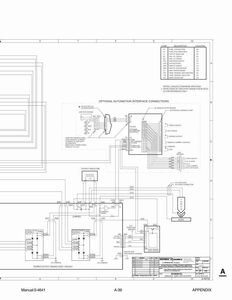
Manual 0-4641 A-39 APPENDIX
A
6
6
7
7
8
8
9
9
10
10
A
B
C
D
E
F
DWG No:
Sheetof
SupersedesScale
Date:
Drawn: References
DateByRevisionsRev PCB No:Assy No:
Information Proprietary to THERMAL DYNAMICS CORPORATION.Not For Release, Reproduction, or Distribution without Written Consent.
NOTE:Unless Otherwise Specified, Resistors are in Ohms 1/4W 5%.Capacitors are in Microfarads (UF) Chk: App:
TITLE:Last Modified:
SizeSCHEMATIC,Thursday, March 24, 2005
1 1
11:05:29
THRU SCREW TERMINAL
PILOT
(E58)
19X1757
DC COM
(E62)
CHASSIS GND
(E35)
ISENSE
(14)(15)
(17)
(18)
F1
COMP DESCRIPTION LOCATION
F2
SW1SW2
FUSE, 1/4A 600V FNQFUSE, 0.9A, RESETABLE
M1M2
FAN, 4.5" 220VAC
B2
B1C1
PS1 PRESSURE SWITCHSOL1 GAS SOLENOID
SWITCH, ON/OFFSWITCH, RUN/SET/RAR
F4F4C1C1
T5 D4TS1TS2 E1
D.Lilja
W1 MAIN CONTACTOR F4
TEMP. SENSOR, IGBT HEATSINKTEMP. SENSOR, INDUCTOR
CURRENT
L1
L1 OUTPUT INDUCTOR D7
MAIN TRANSFORMER
DC COMMON DC COMMON
+12VDCJ40 P40
WORK
TORCH
OUTPUT INDUCTOR
NOTES: UNLESS OTHERWISE SPECIFIED -1. DEPICTIONS OF CIRCUITRY INSIDE PCB BLOCKS
IS FOR REFERENCE ONLY
(REL) DLL
SENSE
Vo
POWER OUTPUT BOARD ASSY 19X1914
CM81/101 600V 3PH SYSTEM 42X1134D
AATHERMAL DYNAMICSINDUSTRIAL PARK No. 2WEST LEBANON, NH 03784603-298-5711
E49 E45E62
E35E43
E61 E3 E1
E58E37 E36 E57
E63
J28 PILOT BOARD
8
5
PLUGS INTO J27ON MAIN BOARD*
45
8
23
1
67
3
54
678
21
5
3
76
4
8
21
CSR
JUMPER
E58 E62
E34AE39A
E50A
E56AE60A
E54AE53A
E48A
E34BE39B
E50B
E48B
E53BE54B
E56BE60B
ASSEMBLYOUTPUT DIODE
19X1757ASSEMBLYOUTPUT DIODE
E64
(E64)(E64)
F3
FAN, 4.5" 220VAC
D1
J2
J1
ALTERNATE 20-PIN HEADER20-POSITION TERMINAL STRIP
54
3
54
6
1
7
23
8
67
19
13
10
16
14
9
15
1211
1817
1817
1920
13
10
16
14
9
15
1211
8
21
20
J4
J3
45
23
8
1
67
45
8
32
7
1
OPTIONAL AUTOMATION INTERFACE CONNECTIONS
6
19X2041
TORCH SW -TORCH SW +
DC COMMON+12VDC
CSRP1
OK TO MOVE
+-
+-
TORCH SWITCH
P3
321 1
23
Vo
DC
GAS
AC
TEMP
(LED PCB 19X1604)
J14 P14
7
1
6
32
8
45
1
5
8
4
67
23
54
6
1
7
23
8
1817
1920
13
10
16
14
9
15
1211
P4
SC-11
+-
DC COMMON
DIVIDED OUTPUT
REMOTE CURRENT CONTROL
C&G
CPCHOUSING
4
143
1265897
OK TO MOVE(+)(-)
LOGIC COMMON(+)(-) ARC VOLTS (C&G)
(+)(-) TORCH SWITCH
ASSY 19X2157
}}}
}
E32
ECO 101136
CSR
RAR OFF
3(46)
(47)(48)(49)
(CSR)(51)(52)
(TS2)(TS1)(NEG)
(56)(57)
(58)(59)
(60)(61)
(62)(63)
(64)
21
21 J1(52)
(51)
HASECO 101314ABHASECO 101429AC
WHEN REMOTE CURRENTCONTROL IS USED WITHAUTOMATION(REPLACES CONNECTIONSFROM J27 TO J14)
ADAPTER HARNESS USED
05/07/03
02/11/0405/07/03
06/09/04
OPTIONALAUTOMATIONINTERFACE
ATC MALE CONNECTORATC RECEIVER
(MODE SW)(C1)
(NEG)(CSR)
ECO 101614 HASAD 03/22/05AE ECO 101664 HAS 03/24/05
A-06752
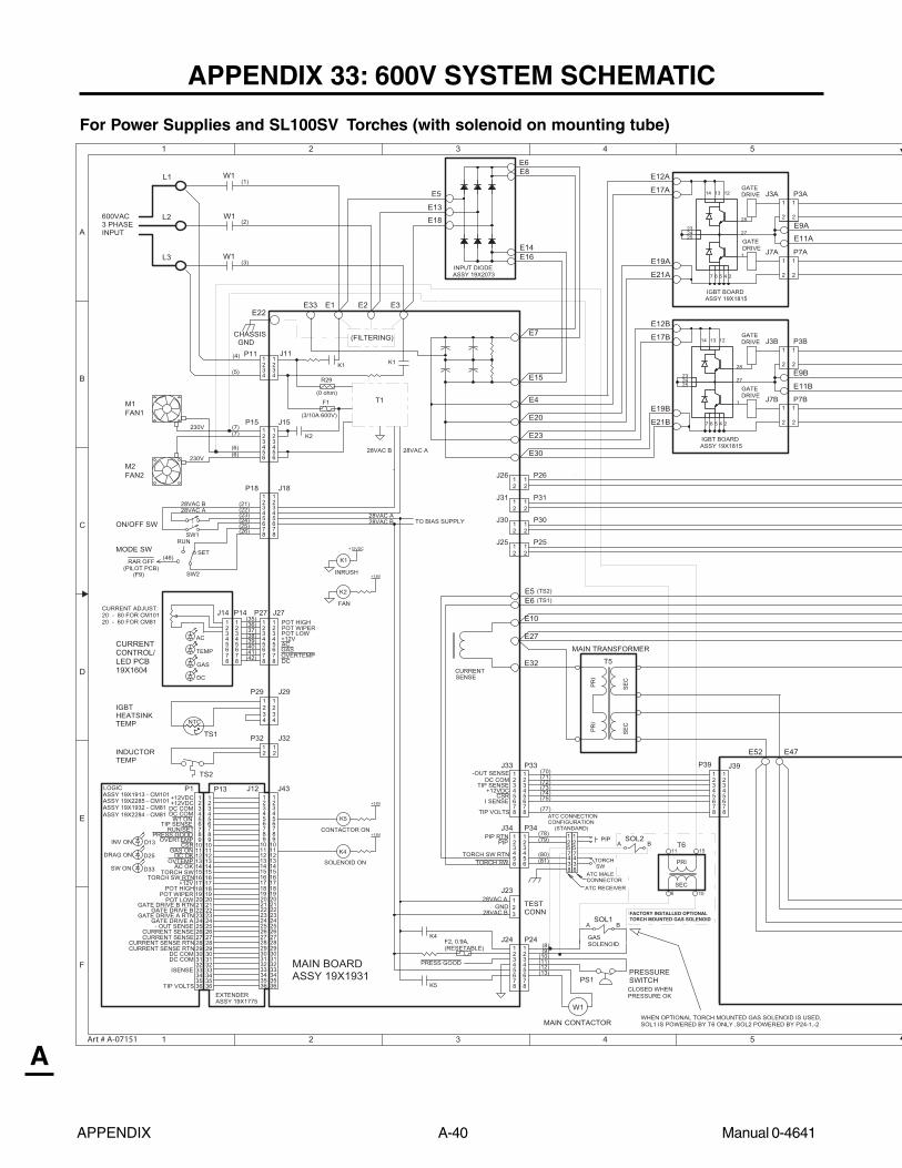
APPENDIX A-40 Manual 0-4641
A
APPENDIX 33: 600V SYSTEM SCHEMATIC
For Power Supplies and SL100SV Torches (with solenoid on mounting tube)1
1
2
2
3
3
4
4
5
5
A
B
C
D
E
F
+12VDC
+18V
+18V
+18V
(22)
600VAC3 PHASEINPUT
TIP SENSEP1
(77)
AC
(23)
(5)
(75)
(3)
230V
(74)
(26)
SEC
GAS
(73)
(7)
GATEDRIVE
(72)
DC
MAIN BOARDASSY 19X1931
GATEDRIVE
ON/OFF SW
CHASSIS GND
(71)
(25)(24)
MODE SW
CURRENTCONTROL/LED PCB19X1604
(70)
W1
3
28VAC B
28VAC B
SET
TIP VOLTS
D13
D33
+12VDC
(6)
TEMP
W1(1)
I SENSE
2
-OUT SENSE
(21)
D25
1
W1
RUN
(4)
PRI
(2)
CSR
28VAC A
CURRENT ADJUST:20 - 80 FOR CM10120 - 60 FOR CM81
INV ON
DRAG ON
(6)
(7)
EXTENDER
28VAC A
SW1
SW2
IGBTHEATSINKTEMP
TS2
INDUCTORTEMP
NTC
1
43
PIP
DC COM
8
(78)(79)
(80)(81)
ASSY 19X1775
P13 J12 J43
P32
P29 J29
J32TS1
J14
P18 J18
FAN1
FAN2
M1
M2
J15P15
P11 J11
230V
(12)(13)
(11)(10)
(8)(9)
INPUT DIODEASSY 19X2073
J25 P25
J30 P30
J31 P31
21J26 P261
ASSY 19X1815
MAIN TRANSFORMER
J7B
J3B
J7A
J3A
P3B
P7B
P3A
P7A
E22
J23
TESTCONN
28VAC A
28VAC BGND
J24 P24
W1
PS1
GASSOLENOID
PRESSURESWITCH
MAIN CONTACTOR
T5
PRI
SEC
P14 P27
J34 P34
J33 P33 P39 J39
E3E2E1
E32
E10
E27
74E25E
E15
E7
E4
E23
E20
E30
IGBT BOARD
E5
E13
E18
E8
E14E16
E6
E12A
E17A
E19A
E21A
E12B
E17B
E19B
E21B
E9A
E11A
E9B
E11B
2
211
2
211
2
112 2
212223
POT LOWGATE DRIVE B RTN
GATE DRIVE BGATE DRIVE A RTN
GATE DRIVE A- OUT SENSE
CURRENT SENSE
CURRENT SENSE RTN
TIP VOLTS
+12V
TORCH SW
PRESS GOOD
POT WIPER
RUN/SETTIP SENSE
CSR
2425262728293031
ISENSE3233
CURRENT SENSE RTN
343536
CURRENT SENSE
OVERTEMP
OVTEMP
+12VDC
DC OK
45
3
67
12
9
15
10
14
16
13
1920
1718
11
8
12
POT HIGH
+12VDC
AC OK
DC COM
TORCH SW RTN
45
3
67
12
9
15
10
14
16
13
1920
1718
11
8
12
21222324252627282930313233343536
21222324252627282930313233343536
45
3
6
12
9
15
10
14
16
13
1920
1718
11
8
12
45
3
67
12
9
15
10
14
16
13
1920
1718
11
8
12
21222324252627282930313233343536
7
DC COMW1 ON
GAS ON
DC COMDC COM
SW ON
(36)
(38)(37)
8
65
23
1
4
78
3
5
2
7
1
4
6
(35)
(41)(40)(39)
(42) 8
67
1
45
23
+12VPOT LOW
OVERTEMP
POT WIPERPOT HIGH
DC
GASAC
8
67
1
45
23
J27
1 122
1234
1
4
23
8
3
5
2
7
1
4
6
8
67
1
45
23
3
5
21
4
6 6
45
23
321
4
1
4
23
8
3
5
2
7
1
4
6
8
67
1
45
23
3
5
21
4
6 6
1
45
23
8
3
5
2
7
1
4
6
8
67
1
45
23
2
1 1
2
2
1 1
2
2
1 1
2
2
1 1
2
TORCH SWTORCH SW RTN
PIPPIP RTN
2
TORCH SW
8
3
5
2
7
1
4
6
8
67
1
45
23
ASSY 19X1815IGBT BOARD
GATEDRIVE
GATEDRIVE
E5E6
CLOSED WHENPRESSURE OK
T1
K2
K1K1
28VAC A28VAC B
(FILTERING)
1
(3/10A 600V)
(0 ohm)
F2, 0.9A,(RESETABLE)
(STANDARD)
ATC CONNECTIONCONFIGURATION
K1
K2
CONTACTOR ON
K5
SOLENOID ON
K4
FAN
INRUSH
K4
K5
TO BIAS SUPPLY
PRESS GOOD
8
21
43
ATC RECEIVER
ATC MALECONNECTOR
SENSECURRENT
RAR OFF(46)
L1
L2
L3
E33
R29
F1
(PILOT PCB)(F9)
(TS2)(TS1)
T6
SOL1BA
11 15
6 10
PRI
SEC
SOL2BA
57
57
WHEN OPTIONAL TORCH MOUNTED GAS SOLENOID IS USED,SOL1 IS POWERED BY T6 ONLY ,SOL2 POWERED BY P24-1,-2
FACTORY INSTALLED OPTIONAL TORCH MOUNTED GAS SOLENOID
ASSY 19X1913 - CM101LOGIC
ASSY 19X1932 - CM81ASSY 19X2285 - CM101
ASSY 19X2284 - CM81
tt
24
12
23
1314
2527
24567
1
28
24
12
23
1314
2527
24567
1
28
Art # A-07151

Manual 0-4641 A-41 APPENDIX
A
6
6
7
7
8
8
9
9
10
10
A
B
C
D
E
F
DWG No:
Sheetof
SupersedesScale
Date:
Drawn: References
DateByRevisionsRev PCB No:Assy No:
Information Proprietary to THERMAL DYNAMICS CORPORATION.Not For Release, Reproduction, or Distribution without Written Consent.
NOTE:Unless Otherwise Specified, Resistors are in Ohms 1/4W 5%.Capacitors are in Microfarads (UF) Chk: App:
TITLE:Last Modified:
SizeSCHEMATIC,Friday, January 27, 2006
1 1DWG No:
Sheetof
SupersedesScale
Date:
Drawn: References
DateByRevisionsRev PCB No:Assy No:
Information Proprietary to THERMAL DYNAMICS CORPORATION.Not For Release, Reproduction, or Distribution without Written Consent.
NOTE:Unless Otherwise Specified, Resistors are in Ohms 1/4W 5%.Capacitors are in Microfarads (UF) Chk: App:
TITLE:Last Modified:
SizeSCHEMATIC,Friday, January 27, 2006
1 1
THRU SCREW TERMINAL
PILOT
(E58)
19X1757
DC COM
(E62)
CHASSIS GND
(E35)
ISENSE
(14)(15)
(17)
(18)
F1
COMP DESCRIPTION LOCATION
F2
SW1SW2
FUSE, 3/10A 600V FNQ-RFUSE, 0.9A, RESETABLE
M1M2
FAN, 4.5" 220VAC
B2
B1C1
PS1 PRESSURE SWITCHSOL1 GAS SOLENOID
SWITCH, ON/OFFSWITCH, RUN/SET/RAR
F4F4C1C1
4D5TTS1
1E2ST
D.Lilja
W1 MAIN CONTACTOR F4
TEMP. SENSOR, IGBT HEATSINKTEMP. SENSOR, INDUCTOR
CURRENT
L1
L1 OUTPUT INDUCTOR D7
MAIN TRANSFORMER
DC COMMON DC COMMON
+12VDCJ40 P40
WORK
TORCH
OUTPUT INDUCTOR
NOTES: UNLESS OTHERWISE SPECIFIED -1. DEPICTIONS OF CIRCUITRY INSIDE PCB BLOCKS
IS FOR REFERENCE ONLY
(REL) DLL
SENSE
Vo
POWER OUTPUT BOARD ASSY 19X1914
CM81/101 600V 3PH SYSTEM 42X1134D
AA THERMAL DYNAMICSINDUSTRIAL PARK No. 2WEST LEBANON, NH 03784603-298-5711
54E94EE62
E35E43
E61 E3 E1
E58E37 E36 E57
E63
J28 PILOT BOARD
8
5
PLUGS INTO J27ON MAIN BOARD*
45
8
23
1
67
3
54
678
21
5
3
76
4
8
21
CSR
JUMPER
E58 E62
E34AE39A
E50A
E56AE60A
E54AE53A
E48A
E34BE39B
E50B
E48B
E53BE54B
E56BE60B
ASSEMBLYOUTPUT DIODE
19X1757ASSEMBLYOUTPUT DIODE
E64
(E64)(E64)
F3
FAN, 4.5" 220VAC
D1
J2
J1
ALTERNATE 20-PIN HEADER20-POSITION TERMINAL STRIP
54
3
54
6
1
7
23
8
67
19
13
10
16
14
9
15
1211
1817
1817
1920
13
10
16
14
9
15
1211
8
21
20
J4
J3
45
23
8
1
67
45
8
32
7
1
OPTIONAL AUTOMATION INTERFACE CONNECTIONS
6
19X2041
TORCH SW -TORCH SW +
DC COMMON+12VDC
CSRP1
OK TO MOVE
+-
+-
TORCH SWITCH
P3
321 1
23
Vo
DC
GAS
AC
TEMP
(LED PCB 19X1604)
J14 P14
7
1
6
32
8
45
1
5
8
4
67
23
54
6
1
7
23
8
1817
1920
13
10
16
14
9
15
1211
P4
SC-11
+-
DC COMMON
DIVIDED OUTPUT
REMOTE CURRENT CONTROL
C&G
CPCHOUSING
4
143
1265897
OK TO MOVE(+)(-)
LOGIC COMMON(+)(-) ARC VOLTS (C&G)
(+)(-) TORCH SWITCH
ASSY 19X2157
}}}
}
E32
ECO 101136
CSR
RAR OFF
3(46)
(47)(48)(49)
(CSR)(51)(52)
(TS2)(TS1)(NEG)
(56)(57)
(58)(59)
(60)(61)
(62)(63)
(64)
21
21 J1(52)
(51)
HASECO 101314ABHASECO 101429AC
WHEN REMOTE CURRENTCONTROL IS USED WITHAUTOMATION(REPLACES CONNECTIONSFROM J27 TO J14)
ADAPTER HARNESS USED
05/07/03
02/11/0405/07/03
06/09/04
OPTIONALAUTOMATIONINTERFACE
ATC MALE CONNECTORATC RECEIVER
(MODE SW)(C1)
(NEG)(CSR)
ECO 101614 HASAD 03/22/05AE ECO 101664 HAS 03/24/05AF RSECO B028 01/09/06AG ECO B016 RWH 01/27/06
Art # A-07151
AH ECO B077 RWH 07/31/06

APPENDIX 34: Publication History
Release Rev. Changes
1/3/05 - Released to production.
2/14/05 - Updated per ECO 101610, adding parts to Spare parts kits.
6/17/05 - Added 415V CE units, ECO 101726.
9/15/05 - Updated 208/230V and 600V schematics, updated work cable clamp.
Feb. 1, 2006 - Added system schematics for system w/ SL100SV Torches (w/ solenoid onmounting tube). Added torch connection diagram and torch pinout diagramsfor torch w/ solenoid. Added transformer for power supplies supporting torchw/ solenoid. Added catalog numbers for torches & leads w/ solenoid & forreplacement leads for torches w/ solenoid. Added publication history to manual.
Mar. 29, 2006 AA Dropped references to leads extensions. Started using new cover style.
April 17, 2006 AB Updated torque spec for input diode to 35 in-lb / 3.95 Nm.
Oct. 5, 2006 AB.01 Added patent information and newer revision control to include two numbers.
Mar. 14, 2007 AC.01 Updated 600 volt schematic to show new fuse.
April 2, 2007 AD.01 Revised Art - Appendix 4, Torch Pin - Out Diagrams:A. Power Supply and SL100SV (without Solenoid) Art A-03900B. Power Supply and SL100SV Torch (with Solenoid) Art A-07114added text to Callout #'s: 3 & 4: Not Used, updated inside & rear cover.

Thermadyne USA2800 Airport RoadDenton, Tx 76207 USATelephone: (940) 566-2000800-426-1888Fax: 800-535-0557Email: [email protected]
Thermadyne Canada2070 Wyecroft RoadOakville, OntarioCanada, L6L5V6Telephone: (905)-827-1111Fax: 905-827-3648
Thermadyne EuropeEurope BuildingChorley North Industrial ParkChorley, LancashireEngland, PR6 7BxTelephone: 44-1257-261755Fax: 44-1257-224800
Thermadyne, ChinaRM 102A685 Ding Xi RdChang Ning DistrictShanghai, PR, 200052Telephone: 86-21-69171135Fax: 86-21-69171139
Thermadyne Asia Sdn BhdLot 151, Jalan Industri 3/5ARawang Integrated Industrial Park - Jln Batu Arang48000 Rawang Selangor Darul EhsanWest MalaysiaTelephone: 603+ 6092 2988Fax : 603+ 6092 1085
Cigweld, Australia71 Gower StreetPreston, VictoriaAustralia, 3072Telephone: 61-3-9474-7400Fax: 61-3-9474-7510
Thermadyne ItalyOCIM, S.r.L.Via Benaco, 320098 S. GiulianoMilan, ItalyTel: (39) 02-98 80320Fax: (39) 02-98 281773
Thermadyne International2070 Wyecroft RoadOakville, OntarioCanada, L6L5V6Telephone: (905)-827-9777Fax: 905-827-9797
GLOBAL CUSTOMER SERVICE CONTACT INFORMATION

Corporate Headquarters16052 Swingley Ridge RoadSuite 300St. Louis, MO 63017Telephone: 636-728-3000Email: [email protected]