PLANT COMMISSIONING/RE-COMMISSIONING … · variation in absorbed dose in food and allied products...
56
i AERB SAFETY GUIDE NO. AERB/RF-RPF/SG-1 PLANT COMMISSIONING/RE-COMMISSIONING DOSIMETRY FOR FOOD AND ALLIED PRODUCTS IN GAMMA RADIATION PROCESSING FACILITIES- CATEGORY II & IV Atomic Energy Regulatory Board Mumbai –400094 India August 2015
Transcript of PLANT COMMISSIONING/RE-COMMISSIONING … · variation in absorbed dose in food and allied products...

i
AERB SAFETY GUIDE NO. AERB/RF-RPF/SG-1
PLANT COMMISSIONING/RE-COMMISSIONING DOSIMETRY
FOR FOOD AND ALLIED PRODUCTS IN
GAMMA RADIATION PROCESSING FACILITIES- CATEGORY II & IV
Atomic Energy Regulatory Board
Mumbai –400094 India
August 2015

ii
Price:
Orders for this ‘safety guide’ should be addressed to:
The Chief Administrative Officer Atomic Energy Regulatory Board
Niyamak Bhavan Anushaktinagar
Mumbai – 400 094 India

iii
FOREWORD
Activities concerning establishment and utilization of nuclear facilities and use of radioactive sources are to be carried out in India in accordance with the provisions of the Atomic Energy Act, 1962. In pursuance of the objective of ensuring safety of occupational workers, members of the public and protection of the environment, the Atomic Energy Regulatory Board (AERB) has been entrusted with the responsibility of laying down safety standards and enforcing rules and regulations for such activities. The Board has, therefore, undertaken a programme of developing safety standards, safety codes, and related guides and manuals for the purpose. While some of these documents cover aspects such as siting, design, construction, operation, quality assurance and decommissioning of nuclear and radiation facilities, other documents cover regulatory aspects of these facilities. Safety codes and safety standards are formulated on the basis of internationally accepted safety criteria for design, construction and operation of specific equipment, structures, systems and components of nuclear and radiation facilities. Safety codes establish the objectives and set requirements that should be fulfilled to provide adequate assurance for safety in nuclear and radiation facilities. Safety guides elaborate various requirements and furnish approaches for their implementation. Safety manuals deal with specific topics and contain detailed scientific and technical information on the subject. These documents are prepared by experts in the relevant fields and are extensively reviewed by advisory committees of the Board before they are published. These documents are revised, when necessary, in the light of experience and feedback from users as well as new developments in the field.
The Gamma Radiation Processing Facilities (GRAPF) are required to obtain licence from AERB under Atomic Energy (Radiation Protection) Rules, 2004. This is a pre-requisite to obtain another licence for processing of food and allied products from DAE under Atomic Energy (Radiation Processing of Food and Allied Products) Rules, 2012. GRAPF carryout plant commissioning/re-commissioning dosimetry to determine absorbed dose profile, statistical variation in absorbed dose in food and allied products and setting of operational parameters. This document provides guidance for developing the standard operating procedures to be followed for conducting the plant commissioning/re-commissioning dosimetry based on the design of the facility, and standard format for preparing the dosimetry report for submission. The results of plant commissioning/re-commissioning dosimetry are verified by BARC.
Consistent with the accepted practice, ‘shall’ and ‘should’ are used in the ‘safety guidelines’ to distinguish between a recommendation and a desirable option respectively. Annexures and references are included to provide further information on the subject that might be helpful to the user(s).
Experts from Board of Radiation and Isotope Technology (BRIT), Mumbai, prepared the first draft of this document. It was reviewed by Safety Committee for Review of Dosimetry for Food Irradiation (SCRDFI) of AERB and Dose Verification Committee, BARC. It has been further

iv

v
DEFINITIONS
Activity The quantity ‘A’ for an amount of radionuclide in a given energy state at a given time is defined as: A = dN/dt Where ‘dN’ is the expectation value of the number of spontaneous nuclear transformations from the given energy state in a time interval ‘dt’. The SI unit of activity is the reciprocal of second (s-1), termed the Becquerel (Bq). Approval A type of regulatory consent issued by the Regulatory Body to a proposal. Atomic Energy Regulatory Board (AERB) A national authority designated by the Government of India having the legal authority for issuing regulatory consent for various activities related to the nuclear and radiation facility and to perform safety and regulatory functions, including their enforcement for the protection of site personnel, the public and the environment against undue radiation hazards. Commissioning The process during which structures, systems and components of a nuclear or radiation facility, on being constructed, are made functional and verified in accordance with design specifications and to have met the performance criteria. Competent Authority Any official or authority appointed, approved or recognised by the Government of India for the purpose of the Rules promulgated under the Atomic Energy Act, 1962.
Dose A measure of the radiation received or absorbed by a target. The quantities termed absorbed dose, organ dose, equivalent dose, effective dose, committed equivalent dose, or committed effective dose are used, depending on the context.

vi
Employer Any person with recognised responsibility, commitment and duties towards a worker in his or her employment by virtue of a mutually agreed relationship. (A self-employed person is regarded as being both a worker and employer). Irradiation Cell An enclosed area in the irradiator where the product is irradiated. Licence A type of regulatory consent, granted by the Regulatory Body for all sources, practices and uses for nuclear facilities involving the nuclear fuel cycle and also certain categories of radiation facilities. It also means authority given by the Regulatory Body to a person to operate the above said facilities. Radiation Cell (See ‘Irradiation Cell’) Regulatory Body (See ‘ATOMIC ENERGY REGULATORY BOARD’) Sealed Source Radioactive source material that is either permanently sealed in a capsule or is closely bounded and in solid form. The capsule or material of a sealed source shall be strong enough to maintain leak tightness under conditions of wear and tear for which the source was designed and also under foreseeable mishaps. Source Anything that causes radiation exposure, either by emitting ionizing radiation or releasing radioactive substances or materials.

vii
SPECIAL DEFINITIONS (Specific for the Present ‘Guide’)
Gamma Irradiation Chamber Gamma Irradiation Chamber is a type of Self-contained dry source storage gamma irradiator. In this irradiator sealed gamma sources are completely contained in a dry container constructed of solid materials. The sealed sources are shielded at all times, and human access to the sealed sources and the volume undergoing irradiation is not normally possible in its design configuration. Gamma Radiation Processing Facility (GRAPF) A radiation processing facility containing radioactive sources emitting gamma radiation and associated systems used for delivering prescribed dose to a specified target in a preset time. Radiation Processing Facility (RPF) A facility containing radiation source and associated systems used for delivering prescribed dose to a specified target in a preset time. GRAPF and IARPF are referred as radiation processing facilities. The term ‘facility’ is often used in this safety code; which shall always mean a RPF, unless specified otherwise. Safety Interlock A safety interlock is an engineered device for precluding likely exposure of an individual to ionizing radiation, either by preventing entry to the controlled area or by automatically removing the cause of the hazard.

ii
CONTENTS
FOREWORD DEFINITIONS SPECIAL DEFINITIONS 1. INTRODUCTION
1.1 General 1.2 Objective 1.3 Scope
2. PURPOSE OF DOSIMETRY 2.1 Purpose 2.2 Information about Facility 3. REQUIREMENTS FOR DOSIMETRY
3.1 Dosimetry Laboratory 3.2 Dosimetry System 3.3 Selection and Procurement of Dosimetry System 3.4 Electron Buildup Caps 3.5 Thermometers 3.6 Stopwatch 3.7 Computation of Absorbed Dose 3.8 Reporting of Absorbed Dose 3.9 Trained Staff
4. DOSE INTER-COMPARISON EXERCISE 4.1 Purpose 4.2 Guidance 5. DUMMY AND DOSIMETRY BOXES
5.1 Preparation of Dummy and Dosimetry Boxes 5.2 Dummy and Dosimetry Boxes 5.3 Preparation of Dummy Boxes 5.4 Preparation of Dosimetry Boxes
6 STEPWISE GUIDANCE DURING DOSIMETRY 6.2 X-Set 6.3 Y- Set 6.4 Z- Set 7 DOSE RESULTS
7.1 Determination of Overdose Ratio (ODR) / Dose Uniformity Ratio (DUR) 7.2 Ultimate Uniformity Ratio (UUR)

iii
7.3 Cycle Time Setting 7.4 Transit Dose Measurement
8 DOSE VERIFICATION
8.1 Purpose 8.2 Steps for Dose Verification
FIGURE-1 PRODUCT BOX POSITIONS IN PRODUCT CARRIERS OF 1, 2 AND 5 SHELVED CARRIER SYSTEM IN GAMMA RADIATION PROCESSING FACILITIES
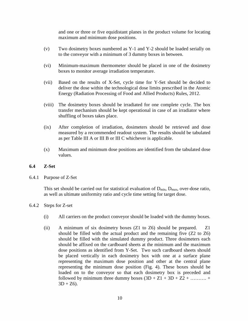
FIGURE-2 POSITION OF DOSIMETERS IN THE CENTRAL
VERTICAL PLAN PARALLEL TO SOURCE FRAME INSIDE THE TOTE/PRODUCT BOX FOR X-SET
FIGURE-3A POSITIONS OF DOSIMETERS IN Y-SET AT SURFACE
AND EQUIDISTANT VERTICAL PLANES INSIDE THE DOSIMETRY BOX
FIGURE-3B PLACEMENT OF A PAIR OF DOSIMETERS IN AN
ARRAY OF THREE-DIMENSIONAL GRID FOR DOSE MAPPING IN Y-SET OF EXPERIMENT
FIGURE-4 PLACEMENT OF DOSIMETERS IN MAXIMUM AND
MINIMUM DOSE POSITIONS IN Z-SET EXPERIMENT ON CENTRAL AND SURFACE VERTICAL PLANES OF THE TOTE/PRODUCT BOX
FIGURE-5 PLACEMENT OF 27 DOSIMETERS IN 3 VERTICAL PLANES FOR DOSE VERIFICATION STUDIES
TABLE-I DOSIMETRY SYSTEMS FOR PLANT
COMMISSIONING/RE-COMMISSIONING DOSIMETRY TABLE-II A ABSORBED DOSE IN X-SET (SINGLE SHELF) TABLE-II B ABSORBED DOSE IN X-SET (2 SHELVED CARRIER) TABLE-II C ABSORBED DOSE IN X-SET (5 SHELVED CARRIER) TABLE-III A ABSORBED DOSE (KGy) IN A SINGLE SHELF CARRIER
TOTE BOX IN Y-SET (5V X 7H PLANES)

iv
TABLE-III B ABSORBED DOSE (KGy) IN A 2-SHELVED CARRIER TOTE BOX IN Y-SET (3V X 5H PLANES)
TABLE-III C ABSORBED DOSE (KGy) IN A 5-SHELVED CARRIER
PRODUCT BOX IN Y-SET (3V X 3H PLANES)
TABLE-IV ABSORBED DOSE (KGy) IN Z–SET TABLE-V FACTORK FOR ONE SIDED NORMAL TOLERANCE
LIMITS ANNEXURE-I CATEGORY OF GAMMA IRRADIATORS ANNEXURE-II FLOW CHART FOR PLANT COMMISSIONING/RE-
COMMISSIONING DOSIMETRY NNEXURE-III LIST OF INSTRUMENTS AND EQUIPMENTS ANNEXURE-IV LIST OF DUMMY MATERIALS FOR DOSIMETRY
PURPOSE ANNEXURE-V PLANT COMMISSIONING/RE-COMMISSIONING
DOSIMETRY REPORT REFERENCES
LIST OF PARTICIPANTS
SAFETY COMMITTEE FOR REVIEW OF DOSIMETRY FOR FOOD IRRADIATION (SCRDFI)
DOSE VERIFICATION COMMITTEE, BARC ADVISORY COMMITTEE ON RADIOLOGICAL SAFETY (ACRS) LIST OF REGULATORY DOCUMENTS ON RADIATION PROCESSING FACILITIES

v

1
1. INTRODUCTION 1.1 General
Radiation processing technology, employing gamma ray sources, is used on a commercial scale for sterilization of medical products, processing of food and allied products, and vulcanization of rubber. This technology involves use of high intensity gamma ray emitting radioisotopes such as Cobalt-60 to deliver a predetermined dose to a specific product under process conditions with access control systems for the radiation processing cell. The number of such Gamma Radiation Processing Facilities (GRAPF) for processing of food and allied products for various purposes such as inhibition of sprouting, insect disinfestations, delaying ripening of fruits and microbial decontamination are increasing in India. The deployment of the intense gamma ray sources in such GRAPF poses radiation hazard for the plant personnel, public and environment in the event of any malfunction or failure of the safety systems. AERB exercises stringent regulatory control during design, construction and operation of such GRAPF. For this purpose, AERB has published the AERB Safety Standard No. AERB/RF-IRRAD/SS-6 (Rev-1), 2007 titled ‘Land-based Stationary Gamma Irradiators’ and AERB Safety Code No. AERB/SC/IRRAD, 1993 titled ‘Operation and Maintenance of Land-based Stationary Gamma Irradiators’. Gamma irradiators are also known as Gamma Radiation Processing Facilities (GRAPF). The terms viz. facility/ irradiator, are also used in this safety guide to refer to a GRAPF.
1.2 Objective The purpose of this guide is to provide detailed information to the facility owners of
gamma radiation processing facilities (GRAPF) regarding the procedures required to be followed for plant commissioning/re-commissioning dosimetry.
1.3 Scope
This safety guide describes the guidance for standard operating procedure (SOP) to be followed while commissioning and re-commissi oning of category II and IV gamma irradiators. This guide prescribes the standard formats for reporting dosimetry results for obtaining requisite licence from the Department of Atomic Energy under Atomic Energy (Radiation Processing of Food and Allied Products) Rules, 2012 [1]. Plant commissioning/re-commissioning dosimetry of all these facilities is carried out to determine absorbed dose profile in food and allied products and setting of operational parameters. It involves procedures such as ensuring proper alignment of source frame to product load in carrier, carrying out dose mapping and setting irradiation time for an intended dose to be delivered to the product [2-5].

2
These facilities have single or multiple shelved carriers, depending on product overlap or source overlap designs, to accommodate product boxes for radiation processing (Fig.1). Industrial gamma radiation processing facilities have been commissioned in different parts of the country which are of different types and categories provided in Annexure I. The flow chart showing the various steps involved in plant commissioning/re-commissioning dosimetry is provided in Annexure-II. This document does not include detailed dosimetry aspects of category I and III gamma irradiators.

3
2. PURPOSE OF DOSIMETRY 2.1 Purpose The purpose of dosimetry is to characterize the distribution, magnitude, and
reproducibility of absorbed dose in a homogeneous material for a typical range of densities and to relate these parameters with operating conditions ensuring optimum utilization of the loaded gamma ray-source.
The commissioning/re-commissioning dosimetry is to be carried out after:
(i) Initial loading of Cobalt-60 source (ii) Replenishment of Cobalt-60 source (iii) Change in the source configuration (iv) Change in the dimensions of irradiation cell (v) Change in carrier’s path inside the irradiation cell around the source-frame (vi) Change in the design of tote/product box/carrier.
(Note: Steps (ii) to (vi) are termed as re-commissioning.)
2.2 Information about Facility The following information is required about the GRAPF before taking up plant
commissioning/re-commissioning dosimetry:
(i) Name and complete address of the facility (ii) Type of facility: Product or source overlap, continuous conveyor or shuffle-
dwell, and batch or bulk flow irradiator (iii) Product exposure: Number of passes around the source and shelves in each
carrier (iv) Product box size (v) Nature of product to be processed (vi) Density and composition of the material intended to be processed (vii) Total number of carriers and number of carriers in each pass facing the
source frame (viii) Cobalt-60 source strength in kCi (vii) Facility ID number allotted by AERB

4
3. REQUIREMENTS FOR DOSIMETRY 3.1 Dosimetry Laboratory Each GRAPF should have a dosimetry laboratory furnished with all calibrated
instruments and equipment required for dose measurement (Annexure III). The laboratory should be air-conditioned to avoid fluctuation in temperature while making dose measurements.
3.2 Dosimetry System It should consist of suitable dosimeters with appropriate readout system for
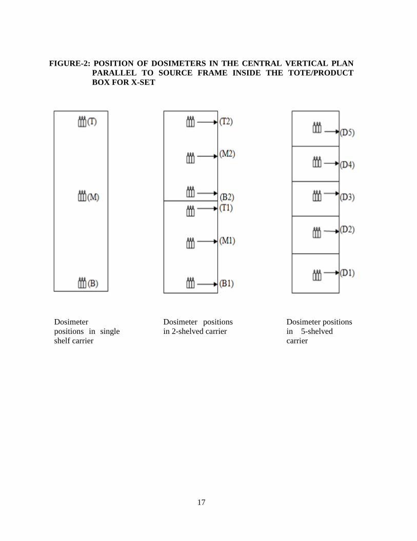
dosimeter response measurement and computation of absorbed dose [6-9]. 3.3 Selection and Procurement of Dosimetry System Proper dosimetry system should be selected from Table I, based on the required dose
range for the product to be irradiated in the facility. Facility should obtain adequate number of dosimeters (Routine/Process dosimeters) from an approved manufacturer/supplier, along with a calibration graph or a mathematical relation to convert the dosimeter readings/response into dose. A copy of traceability certificate issued by the National Standard Laboratory, Radiation Standard Section (RSS), Bhabha Atomic Research Centre (BARC) for dosimeter batch procured should also be obtained from the manufacturer/supplier. Check should be made on the date of manufacture and of expiry for the particular batch of dosimeters. Fricke dosimeters, produced in-house, should comply with ASTM Standard Code of Practice, E1026 (Latest Publication).
3.4 Electron Buildup Caps To achieve uniform and accurate dose, it is necessary to use suitable electron build-
up caps (Polystyrene/Perspex/Nylon) of thickness equivalent to 5 mm of unit density material for Cobalt-60 based irradiator for dosimeters such as Fricke, ceric-cerous and film dosimeters. For Cesium-137 based irradiators build-up caps of 3 mm thickness of unit density material should be used.
3.5 Thermometers Calibrated thermometers for measurement of maximum and minimum temperature
of product during irradiation and dose evaluation should be used as specified in Annexure-III.

5
3.6 Stopwatch A calibrated stopwatch should be used to set and check the cycle time/dwell time as
specified in Annexure-III. 3.7 Computation of Absorbed Dose Suitable software/calibration chart supplied by the manufacturer of dosimeters
should be used for computation of absorbed dose. In case the response of dosimeter used is affected by humidity, light, time delay in dose measurement, necessary correction should be made before reporting the absorbed dose. All dose values should be rounded off to second decimal place.
3.8 Reporting of Absorbed Dose Absorbed dose should be computed and reported at 25oC by applying appropriate
correction for irradiation temperature and dose measuring temperature. 3.9 Trained Staff Dosimetry should be carried out only by trained dosimetry staff who have undergone
‘AERB approved certification course for plant operators and radiological safety officers of Gamma Radiation Processing Facilities (GRAPF)’. These courses are conducted as per the syllabus approved by AERB and provided in AERB Standard Syllabi: AERB/RF/Training-Syllabi/2012 titled ‘Standard Syllabi for Training Courses on Radiological Safety’.

6
4. DOSE INTER-COMPARISON EXCERCISE
4.1 Purpose GRAPF should carry out dose inter-comparison exercise under controlled irradiation
conditions for the dosimeter batch intended to be used for plant commissioning/re-commissioning dosimetry with the National Standard Laboratory (NSL) (RSS, BARC, Modular Laboratory, Trombay, Mumbai-400085). The purpose of this exercise is to ensure:
(i) traceability of dose measurements to NSL, (ii) competence of a irradiation facility to measure absorbed dose, and (iii) preparedness of the facility for dosimetry.
4.2 Guidance The facility should send 30 Nos. of dosimeters per procured/produced dosimeter
batch to NSL for dose inter-comparison. NSL will irradiate the dosimeters, in a calibrated Gamma Irradiation Chamber in a fixed geometry to three different known doses within the dose range of the dosimeter and return them to the facility in about two weeks’ time from the date of receipt of the routine/process dosimeters. The facility should carry out evaluation of irradiated dosimeters and send the results to the NSL. NSL will compare the dose values measured by the facility with those delivered by NSL. The NSL will send the results to the concerned facility. The agreement between these values should be within ± 3% (1σ). If the dose values differ by more than ± 3%, the dose inter-comparison exercise should be repeated with new set of dosimeters.

7
5. DUMMY AND DOSIMETRY BOXES 5.1 Preparation of Dummy and Dosimetry Boxes It is preferable to use the actual product for dosimetry. In case the actual product is
not available, a material having comparable bulk density and homogeneous nature similar to the product to be processed should be used as dummy material in consultation with dosimetry experts for commissioning/re-commissioning dosimetry. Dummy material such as rice husk, saw dust or mixture of rice husk and saw dust, dry raisins or product consisting of low atomic weight elements such as C, H, O, N should be used. The density of dummy material should be within ± 10% of the actual product density. A list of a few dummy materials is given in Annexure-IV.
5.2 Dummy and Dosimetry Boxes Corrugated cardboard carton, tote box, gunny bags, plastic crates and high density
polyethylene (HDPE) bags should be used for preparation of dummy and dosimetry boxes. The dummy boxes are those, which are filled with dummy material. The dosimetry boxes are those, which are filled with product/dummy material having dosimeters placed at the designated positions.
5.3 Preparation of Dummy Boxes The dummy boxes should be filled in such a way as to fulfill the requirement of bulk
density of the product to be processed during routine irradiation. Weight of each dummy box should be noted. While selecting a mixture of materials as dummy product, care should be taken to see that dummy material remains homogeneous and none of the components settle during irradiation. All carriers should be loaded with the dummy boxes before starting the plant commissioning/re-commissioning dosimetry.
5.4 Preparation of Dosimetry Boxes
Dosimeters should be affixed at specified positions on cardboard sheets and placed inthe dosimetry boxes for X, Y and Z sets of measurements for the plant commissioning/re-commissioning dosimetry.

8
6. STEP-WISE GUIDANCE DURING DOSIMETRY 6.1 Three (X, Y and Z) Sets Plant commissioning/re-commissioning dosimetry should be carried out in the three
sets of measurements viz. X-Set, Y-Set and Z-Set. Prior to commencing the plant commissioning/re-commissioning dosimetry, it should be well established that pneumatic, hydraulic, electromechanical and safety systems of the plant are in place and working satisfactorily and plant runs at least for 24 hours with full load of dummy boxes without any interruption.
6.2 X-Set 6.2.1 Purpose of X-Set This set is carried out to ensure the central alignment of the source frame with
respect to tote/product box in carrier(s). This set reflects maximum utilization of radiation energy of the source by the products. This is achieved by assessing vertical dose distribution in the central plane of the tote/product box. Normally the magnitude of absorbed dose along the central vertical plane at the top and bottom positions of the product carrier should be the same. If the dose values at the two extreme ends differ by more than 5 percent, then the position of source frame should be adjusted by raising or lowering the ropes holding the source frame. Source position also influences the over-dose ratio (ODR). Therefore, it is mandatory to run the X-set as a first step of the plant commissioning/re-commissioning dosimetry.
6.2.2 Steps for X-set
(i) All carriers on the product conveyor should be loaded with the dummy boxes. (ii) For 1 or 2 shelved carrier, a set of three dosimeters should be affixed at the
top, middle and bottom position of cardboard sheet; for 5 shelved carrier, a set of three dosimeters should be affixed at the geometric center of the cardboard sheet (Fig. 2). These sheets should be placed in the central vertical plane of the product/tote box filled with the dummy material to its designed weight limit.
(iii) 1, 2 and 5 dosimetry boxes should be placed in case of 1, 2 and 5 shelved
carrier(s), respectively on one of the carriers. (iv) Minimum-maximum thermometer should be placed in one of the dosimetry
boxes to monitor the average irradiation temperature. (v) The cycle time/ dwell time should be decided on the basis of (i) Cobalt-60
source activity, (ii) number of passes on either side of the source frame, and (iii) dose range of the dosimeter.

9
(vi) Irradiation should be carried out for a number of cycles so as to deliver a dose
within the dose range of the dosimeter used. In case of an irradiator where shuffling of boxes takes place, the shuffling mechanism should not be operational during X- set dosimetry.
(vii) After completion of irradiation, dosimeters should be retrieved and the dose
should be measured by a readout system. The results should be tabulated as per Table II A or II B or II C whichever is applicable.
(viii) If the percentage of dose variation at top and bottom positions of the product
carriers is ≤ 5%, Y-set (see para 6.3) should be carried out. But if the percentage of dose variation is >5%, source frame adjustment should be carried out. If source frame is adjusted, steps (ii) to (vii) mentioned above should be repeated.
6.3 Y- Set
6.3.1 Purpose of Y-Set This set is carried out to determine the absorbed dose profile in the volume of the
box occupied by the product/dummy material and also to locate minimum dose (Dmin) and maximum dose (Dmax) positions inside the product. Mapping of the absorbed dose distribution by three dimensional grid of dosimeters in the process load (product/dummy material) is carried out. The amount of product/dummy material in the process load should be the same (i.e. by volume and density) as is expected to be loaded in the actual process run.
6.3.2 Steps for Y-set
(i) All carriers on the product conveyor should be loaded with the dummy boxes.
(ii) Two dosimetry boxes, for both food and allied product dosimetry should be prepared and used. One box (Y-1) should contain the actual food or allied product and another box (Y-2) should contain the dummy material.
(iii) A pair of dosimeters should be firmly affixed at equal distance on the cardboard sheet in 3 rows and 3 columns (i.e. minimum 3 planes), constituting overall 9 dosimeter positions for a box of size not exceeding 45 x 45 x 45 cm. If any dimension exceeds 45 cm but is less than 100 cm, use of minimum 5 planes, and if it exceeds 100 cm but is less than 150 cm, then use of minimum 7 planes in that direction for placement of dosimeters is recommended (Fig. 3A and 3B).
(iv) The cardboard sheets, affixed with dosimeters, should be placed vertically at
an equal distance in the dosimetry box. These constitute two surface planes
10
and one or three or five equidistant planes in the product volume for locating maximum and minimum dose positions.
(v) Two dosimetry boxes numbered as Y-1 and Y-2 should be loaded serially on
to the conveyor with a minimum of 3 dummy boxes in between. (vi) Minimum-maximum thermometer should be placed in one of the dosimetry
boxes to monitor average irradiation temperature. (vii) Based on the results of X-Set, cycle time for Y-Set should be decided to
deliver the dose within the technological dose limits prescribed in the Atomic Energy (Radiation Processing of Food and Allied Products) Rules, 2012.
(viii) The dosimetry boxes should be irradiated for one complete cycle. The box
transfer mechanism should be kept operational in case of an irradiator where shuffling of boxes takes place.
(ix) After completion of irradiation, dosimeters should be retrieved and dose
measured by a recommended readout system. The results should be tabulated as per Table III A or III B or III C whichever is applicable.
(x) Maximum and minimum dose positions are identified from the tabulated dose
values.
6.4 Z-Set 6.4.1 Purpose of Z-Set This set should be carried out for statistical evaluation of Dmin, Dmax, over-dose ratio,
as well as ultimate uniformity ratio and cycle time setting for target dose. 6.4.2 Steps for Z-set
(i) All carriers on the product conveyor should be loaded with the dummy boxes. (ii) A minimum of six dosimetry boxes (Z1 to Z6) should be prepared. Z1
should be filled with the actual product and the remaining five (Z2 to Z6) should be filled with the simulated dummy product. Three dosimeters each should be affixed on the cardboard sheets at the minimum and the maximum dose positions as identified from Y-Set. Two such cardboard sheets should be placed vertically in each dosimetry box with one at a surface plane representing the maximum dose position and other at the central plane representing the minimum dose position (Fig. 4). These boxes should be loaded on to the conveyor so that each dosimetry box is preceded and followed by minimum three dummy boxes (3D + Z1 + 3D + Z2 + ………. + 3D + Z6).

11
(iii) The cycle time for this exercise should be set for a target dose on the basis of
results of Y-set. For food and allied products, the target dose should be such that the technological dose limits are not violated.
(iv) The dosimetry boxes should be irradiated for the intended dose. The box
transfer mechanism should be kept operational in case of an irradiator where shuffling of boxes takes place.
(v) After completion of irradiation, dosimeters from Dmin and Dmax positions
should be retrieved and the dose measured by a recommended readout system. The results should be tabulated as per Table IV.
(vi) The average minimum dose and average maximum dose along with standard
deviation and percent coefficient of variation should be calculated. Over-dose ratio and ultimate uniformity ratio should then be determined from the average minimum dose and average maximum dose values.
(vii) Based on the results of Z- set, the cycle time for routine radiation processing
should be set to deliver the dose within the technological dose limits prescribed in the Atomic Energy (Radiation Processing of Food and Allied Products) Rules, 2012.

12
7. DOSE RESULTS 7.1 Determination of Over-dose Ratio (ODR) / Dose Uniformity Ratio (DUR) The ratio of maximum dose to minimum dose ( Dmax/Dmin) is expressed as ODR or
DUR. It depends on the size of the product box, product density and source configuration and conveyor system inside the cell.
7.2 Ultimate Uniformity Ratio (UUR) This can be calculated for a confidence level of 95% using tolerance factor k given in
Table V[10].
Limiting maximum dose in kGy
D limmax = Average maximum dose (Dmax) + k x (S.D.)1--------- (7.1)
Limiting minimum dose in kGy
D limmin =Average minimumdose (Dmin) -k x (S.D.)2---------- (7.2)
Ultimate Uniformity Ratio = Limiting maximum dose / Limiting minimum dose
= D limmax / D
limmin ------------------------ (7.3)
For food dosimetry:
Target maximum dose in kGy = Dmax – k x (S.D.)1------------------ (7.4)
Target minimum dose in kGy = Dmin + k x (S.D.)2------------------ (7.5)
(Dmax and Dmin values are as per the existing regulatory requirements.)
Where (S.D.)1and (S.D.)2 are the standard deviation values for average maximum and average minimum dose respectively obtained from Z- set.
7.3 Cycle Time Setting
The cycle time or conveyor speed is set on the basis of calculated target minimum dose from the results obtained in the Z-set. It is recommended that the cycle time should be adjusted every month taking into consideration the decay of the Cobalt-60 source.
The results of plant commissioning/ re-commissioning dosimetry should be reported as
per the format given in Annexure–V.

13
7.4 Transit Dose Measurement The dose received by the product during the movement of source from the shielded
to the exposed position and vice versa is defined as transit dose. For high dose applications, the transit dose is too small compared to absorbed dose to be delivered to the product and is treated as negligible.
However, for low dose applications such as sprout inhibition in onions and potatoes,
contribution of transit dose may be significant to the absorbed dose and therefore proper care should be taken to set cycle time. When frequent plant breakdown occurs during the irradiation process, contribution of transit dose to total dose becomes important and must be considered. Therefore the average transit dose must be determined during plant commissioning/re-commissioning dosimetry, particularly for low dose applications in radiation processing facilities.

14
8. DOSE VERIFICATION
8.1 Purpose Atomic Energy (Radiation Processing of Food and Allied Products) Rules, 2012
require establishing documentary evidence that food processed by the facility has received doses within the recommended technological dose limits. All these measurements should be traceable to national/international standards through an unbroken chain. Radiation Standards Section (RSS) of BARC is entrusted with the task of carrying out verification of dosimetry. Hence, it is mandatory to carry out dose inter-comparison exercise in the actual food product to be processed using routine process dosimeter of plant and the Transfer Standard Dosimeters supplied by RSS, BARC as per the written instructions provided below. This exercise is to be carried out by the facility after commissioning/re-commissioning dosimetry is carried out. A copy of results of this exercise should be part of the dosimetry report to be submitted for obtaining the licence.
8.2 Steps for Dose Verification
(i) The facility should utilize the transfer standard dosimeters supplied by RSS, BARC or any other organisation accredited for the purpose of carrying out process validation dosimetry.
(ii) The facility should obtain at least 27 numbers of transfer standard dosimeters.
(iii) The facility should perform the dose distribution measurement, at least in one product box, using minimum three different symmetric vertical planes parallel to the source frame. The process dosimeters that are used for carrying out dose inter-comparison exercise in a Gamma Irradiation Chamber should be utilized as routine dosimeters along with transfer standard dosimeters. This dose distribution should be carried out using actual product.
(iv) The number of dosimeters to be placed per plane should be at least nine and distributed symmetrically in 3 rows and 3 columns with at least 2 to 3 cm margin from edges of the plane. At each point routine dosimeter and reference dosimeter should be placed side by side (i.e. adjacent to each other). This arrangement produces a 27 point three dimensional grid for dose mapping in the product box to ascertain the position and value of Dmin and Dmax as shown in the enclosed Fig. 5.
(v) The facility should evaluate their dosimeters and send their results to RSS, BARC along with irradiated transfer standard dosimeters of RSS.

15
(vi) RSS, BARC will compare these results with their measured dose values and communicate the results and recommendations to the concerned authority. The agreement in the dose values of the Applicant and RSS should be within ± 10% (1σ) [11].

16
FIGURE-1: PRODUCT BOX POSITIONS IN PRODUCT CARRIERS OF 1, 2 AND 5 SHELVED CARRIER SYSTEM IN GAMMA RADIATION PROCESSING FACILITIES
Single-shelf Carrier
2-Shelved Carrier 5-Shelved Carrier
17
FIGURE-2: POSITION OF DOSIMETERS IN THE CENTRAL VER TICAL PLAN
PARALLEL TO SOURCE FRAME INSIDE THE TOTE/PRODUCT BOX FOR X-SET
Dosimeter positions in single shelf carrier
Dosimeter positions in 2-shelved carrier
Dosimeter positions in 5-shelved carrier

18
FIGURE – 3A : POSITIONS OF DOSIMETERS IN Y-SET AT SURFACE AND
EQUIDISTANT VERTICAL PLANES INSIDE THE DOSIMETRY BOX
Dosimeter Box in single shelf carrier
Dosimeter positions on cardboard sheet
Dosimeter Box in 2-shelved carrier
Dosimeter positions on cardboard sheet
Dosimeter positions on cardboard sheet Dosimeter Box in
5-shelved carrier

19
FIGURE – 3B: PLACEMENT OF A PAIR OF DOSIMETERS IN AN ARRAY OF THREE-DIMENSIONAL GRID FOR DOSE MAPPING IN Y-SET OF EXPERIMENT
Each vertical plane contains 25 pairs of dosimeters in equally spaced 5 columns and 5 rows.

20
FIGURE – 4: PLACEMENT OF DOSIMETERS IN MAXIMUM AND MINIMUM DOSE POSITIONS IN Z-SET EXPERIMENT ON CENTRAL AND SURFACE VERTICAL PLANES OF THE TOTE/PRODUCT BOX
Dosimeter Box in 5-shelved carrier
Dosimeter Box in 2-shelved carrier
Dosimeter Box in single shelf carrier

21
FIGURE –5: PLACEMENT OF 27 DOSIMETERS IN 3 VERTIC AL PLANES FOR DOSE VERIFICATION STUDIES
22
TABLE I: DOSIMETRY SYSTEMS FOR PLANT COMMISSIONING/ RE-COMMISSIONING DOSIMETRY
Dosimeter Readout System Usable Absorbed
Dose Range (in Gy)
ASTM No.
Alanine Electron Paramagnetic Resonance spectrometer
1 - 105
1607
Dyed polymethyl methacrylate
Spectrophotometer
102 - 105 1276
Clear polymethyl methacrylate
Spectrophotometer
102 - 105 1276
Cellulose tri acetate Spectrophotometer
104 - 4 x 10⁵ 1650
Lithium borate, lithium fluoride
Thermoluminescence reader
10 -4 - 103
-
Lithium fluoride(optical grade)
Spectrophotometer
102-106 -
Radiochromic dye films solution,
Optical wave guide
Spectrophotometer
1-105
1275
1310
Ceric Cerous sulfate solution
Spectrophotometer or potentiometer
103-105 1205
Ferrous sulfate solution Spectrophotometer
20 – 4 x10² 1026
Potassium/Silver dichromate
Spectrophotometer
103-105 1401
Ferrous cupric sulfate solution
Spectrophotometer
103-5 x 10³ -
Ethanol chlorobenzene solution
Spectrophotometer, colour titration, high
frequency conductivity 10 - 2 x10⁶ 1538
Amino acids Lyo luminescence reader 10 - 104
Metal oxide semiconductor
Field effect Transistor (MOSFET)
Voltmeter
1-102 -
Note: Relevant ASTM practice shall be followed for use of dosimetry system (Dosimeters should be procured from a standard manufacturer conforming to the batch to batch tolerances as prescribed under the ASTM standards or as acceptable to the NSL)

23
TABLE-II A: ABSORBED DOSE IN X-SET (SINGLE SHELF)
Dosimeter Position in Central Vertical Plane of the TOTE/Product Box
Dose (kGy)/cycle
Ratio of Dose Received in Symmetrical
Positions
% Change in Symmetrical
Positions (Not to exceed
5%) Top (T)
T/B = Middle (M) Bottom (B)
(Each reading is an average of three dosimeters readings)
TABLE-II B: ABSORBED DOSE IN X-SET (2 SHELVED CARRI ER)
Shelf
Dosimeter Position in
Central Vertical Plane
of the TOTE/Product
Box
Dose (kGy)/cycle
Ratio of Dose Received in Symmetrical
Positions
% Change in Symmetrical
Positions (Not to
exceed 5%)
Upper
(2)
Top (T2) T2/B1 =
Middle (M2) Bottom (B2)
M2/M1 =
Lower
(1)
Top (T1) Middle(M1)
B2/T1=
Bottom (B1) (Each reading is an average of three dosimeters readings)

24
TABLE-II C: ABSORBED DOSE IN X-SET (5 SHELVED CARRI ER)
Shelf
Dosimeter Position in
Central Vertical
Plane of the TOTE/Prod
uct Box
Dose (kGy)/cy
cle
Ratio of Dose Received in Symmetrical
Positions
% Change in Symmetrical
Positions (Not to exceed
5%)
5 (Top) D-5 D-5/D-1=
4 D-4 3 D-3 2 D-2
D-4/D-2=
1(Bottom) D-1 (Each reading is an average of three dosimeters readings)

25
TABLE – III A: ABSORBED DOSE (kGy) IN A SINGLE SHEL F CARRIER TOTE
BOX IN Y-SET (5V X 7H PLANES) Dosimeter Position
Plane A Plane B Plane C Plane D Plane E
1 2 3 4 5 6 7 8 9 10 11 12 13 14 15 16 17 18 19 20 21 22 23 24 25 26 27 28 29 30 31 32 33 34 35
Average S.D.±±±±
C.V. (%) (Each reading is an average of two dosimeters readings) Minimum dose position = ……., Maximum dose position = …………………………….

26
TABLE – III B: ABSORBED DOSE(kGy) IN A 2-SHELVED C ARRIER TOTE BOX IN Y-SET (3V X 5H PLANES)
Dosimeter Position
Plane A Plane B Plane C Plane D Plane E
1 2 3 4 5 6 7 8 9 10 11 12 13 14 15
Average S.D.±±±±
C.V. (%) (Each reading is an average of two dosimeters readings) Minimum dose position = ………………………., Maximum dose position = ……………… TABLE – III C: ABSORBED DOSE kGy IN A 5-SHELVED C ARRIER PRODUCT
BOX IN Y-SET (3V X 3H PLANES)
Dosimeter Position
Surface Plane A Middle Plane B Surface Plane C
1 2 3 4 5 6 7 8 9
Average S.D.±±±±
C.V. (%) (Each reading is an average of two dosimeters readings) Minimum dose position = ………………, Maximum dose position = ………………

27
TABLE –IV: ABSORBED DOSE kGy IN Z–SET
Dosimeter Box No.
Dose at Dmax Position Dose at Dmin Position
Z-1 Z-2 Z-3 Z-4 Z-5 Z-6
Average dose Dmax Dmin S.D.±±±± (S.D.)1 (S.D.)2
C.V. (%) (Each reading is an average of three dosimeters readings)

28
TABLE – V: FACTOR k FOR ONE SIDED NORMAL TOLERANCE
LIMITS
n = number of readings 100γ is the confidence level in %, 100(1-α) is the percentage of population below (or above) tolerance limits.

29
ANNEXURE-I
CATEGORY OF GAMMA IRRADIATOR
The irradiators are categorized in terms of the design of the irradiator with respect to configuration of the product irradiation position, accessibility and shielding of radioactive source. Category-I: Self-contained, dry source storage An irradiator in which the sealed source is completely contained in a dry container constructed of solid materials, the sealed source is shielded at all times, and human access to the sealed source and the volume undergoing irradiation is not physically possible in its designed configuration. Category-II: Panoramic, dry source storage A controlled human access irradiator in which the sealed source is contained in a dry container constructed of solid materials, the sealed source is fully shielded when not in use; the sealed source is exposed within a radiation volume that is maintained inaccessible during use by an entry control system. Category-III: Self-contained, wet source storage An irradiator in which the sealed source is contained in a storage pool (usually containing water), the sealed source is shielded at all times, and human access to the sealed source and the volume undergoing irradiation is physically restricted in its designed configuration and proper mode of use. Category-IV: Panoramic, wet source storage A controlled human access irradiator in which the sealed source is contained in a storage pool (usually containing water), the sealed source is fully shielded when not in use; the sealed source is exposed within a radiation volume that is maintained inaccessible during use by an entry control system.

30
ANNEXURE-II
FLOW CHART FOR PLANT COMMISSIONING/RE-COMMISSIONING DOSIMETRY
Cobalt-60 Source Loading/Replenishment
Preparation of Dummy Boxes (With Simulated Product)
Placement of Dosimeters on Cardboard Sheets for Dosimetry (For X, Y and Z-Set)
Preparation of Dosimetry Boxes (For X, Y and Z-Set)
X-Set (For Alignment of Source to Product Load)
(For X, Y and Z-Set)
Y-Set (For Dose Mapping and Identification of Minimum & Maximum
Dose Positions)
Z-Set (For Statistical Evaluation of Dmin& Dmax, Over-Dose Ratio &
Ultimate Dose Uniformity Ratio)
Setting of Cycle Time (For Product Processing)

31
ANNEXURE-III
LIST OF INSTRUMENTS AND EQUIPMENT
1. Digital voltmeter:
Specification: Readout: Up to two decimals Range of measurements: 0 to ± 199.9 mV Accuracy: ± 0.05 % , least count 0.01mV Power: 230 ±10 % Volt AC Frequency of calibration and documentation : Annual 2. UV-VIS Spectrophotometer:
Specification: Standard specifications. Wavelength range: 190 – 900 nm Wavelength accuracy: ± 1 nm. Temperature controlled cell compartment. 10 mm quartz cell and holder for film dosimeters Frequency of calibration and documentation: Every six months (for optical response
and wavelength). 3. Thermometers:
(i) Thermometer used during dose measurement (range: 0 to 50oC) ; Least count: 0.1oC
(ii) Minimum- maximum thermometer used during product irradiation (range: 0 to 50oC); Least count: 0.5oC
(iii) Minimum- maximum thermometer used during frozen product irradiation (range: -50 to 50oC); Least count: 0.5oC
Frequency of calibration: Annual 4. Electrochemical Cell:
Use calibrated electrochemical cell as per the specifications given below. Made of non-leachable Corning/Pyrex glass having two compartments A and B separated by a glass frit of porosity <2µm and fitted with platinum electrodes for measurement of potential difference across the glass frit using potentiometer or mV meter [Figure A III (a), and Figure A III (b)].
5. Water Distillation Unit: All glass distillation unit.
6. Stopwatch:
Stopwatch with least count 0.1 seconds. Frequency of calibration: Annual (Note: Different dosimeters may require different readout systems that should be calibrated
periodically with suitable standards.)

32
Figure A III (a) : Schematic Diagram of Electrochemical Cell for Measurement of Potential Difference Across a Glass Frit
Figure A III(b): Potentiometric Readout System

33
ANNEXURE-IV
LIST OF DUMMY MATERIALS FOR DOSIMETRY PURPOSE
S. No.
Bulk
Density
(kg/l)
Simulated Product
1 0.15 - 0.2 Rice husk, saw dust, wooden chips , ground nut shell
2 0.3-0.5 Raisins , rice bran powder, coir
3 0.5 -0.6 Ragi flour, flour of various cereals, betel nut powder, poha powder
4 0.7-0.8 Bajra seeds and its flour

34
ANNEXURE-V
PLANT COMMISSIONING/RE-COMMISSIONING DOSIMETRY REP ORT
Date: dd/mm/yyyy
1. Facility Details 1.1. Name and complete address of the facility: 1.2. ID No. allotted by AERB: 1.3. Type of facility: (product/source overlap) 1.4. Conveyor system: (pneumatic/hydraulic) 1.5. Product processing: (batch/continuous) 1.6. Number of carriers: 1.7. Shelves in each carrier: 1.8. Tote/box size: (l x h x w) in cm 1.9. Source activity: (as on dd/mm/year)………….kCi 1.10. Activity loaded:…………….kCi 1.11. Total activity:……………….kCi as on dd/mm/yyyy 1.12. Total number of source pencils: (attach a diagram) 1.13. Dummy material (if blended give ratio): 1.14. Weight of empty tote/product box: ……………kg 1.15. Tote/product box: (i) material………………….(ii) thickness……………..mm 1.16. Weight of tote/product box + dummy material:…………kg 1.17. Volume of the tote/product box : …………….litres 1.18. Weight of dummy material:……………..kg 1.19. Volume of the tote/product box occupied by the product:………………..litres 1.20. Bulk density: kg/litre
2. Purpose: 2.1. Name of the product to be processed: 2.2. Purpose of irradiation:
3. Dosimetry system employed: 3.1. Dosimeters used: 3.2. Dose range: 3.3. Batch number: 3.4. Dosimeter composition: 3.5. Density of dosimeter solution: 3.6. Electron buildup (i) Material: (ii) thickness: mm. 3.7. Dose readout system used: 3.8. Traceability: Give details of inter-comparison carried out with RSS, BARC. 4. Dosimetry Procedure: Carried out in three sets of experiments. 4.1. X- Set: To monitor the vertical dose distribution along the central plane of product
load in carrier to ascertain the source to product load alignment and to set the cycle time for Y-set. All carriers are occupied by dummy tote/product boxes filled with

35
dummy material. One carrier is loaded with dosimeter tote/product boxes in all the shelves. Three dosimeters are placed in each position for dose measurement. Cardboard sheet/sheets vertically passing through the geometrical centre of the product box and parallel to source frame is used for placing dosimeters.
4.1.1. Date: From…………..to……………….. 4.1.2. Placement of dosimeters: Attach a diagram. 4.1.3. Weight of the product in dosimeter tote/product box: 4.1.4. Volume of the tote/product box occupied by the product: 4.1.5. Bulk density of the dosimeter box: 4.1.6. Tote/product box transfer system: OFF 4.1.7. Cycle time (in minutes): 4.1.8. Number of cycles: 4.1.9. Total irradiation time (hours and minutes): 4.1.10. Plant breakdown time (hours and minutes): 4.1.11. Number of occasions source went in shielded position due to breakdown: 4.1.12. Irradiation temperature (oC): 4.1.13. Dose measuring temperature (oC): 4.1.14. Results are tabulated as given below:
TABLE V-1 : AVERAGE ABSORBED DOSE IN X-SET (SINGLE SHELF)
Dosimeter Position in Central Vertical Plane of the TOTE/Product Box
Dose (kGy)/cycle
Ratio of Dose Received in Symmetrical
Positions
% Change in Symmetrical
Positions (Not to exceed
5%) Top (T)
T/B = Middle (M) Bottom (B)
Each reading is an average of 3 dosimeters reading. or
TABLE V-2: AVERAGE ABSORBED DOSE IN X-SET (2 SHELVE S)
Shelf
Dosimeter Position in
Central Vertical Plane
of the TOTE/Product
Box
Dose (kGy)/cycle
Ratio of Dose Received in Symmetrical
Positions
% Change in Symmetrical
Positions (Not to exceed
5%)
Upper
(2)
Top (T2) T2/B1 =
Middle (M2) Bottom (B2)
M2/M1 =
Lower
(1)
Top (T1) Middle(M1)
B2/T1=
Bottom (B1)

36
Each reading is an average of 3 dosimeters readings. Or
TABLE V-3: AVERAGE ABSORBED DOSE IN X-SET (5 SHELVE S)
Shelf
Dosimeter Position in
Central Vertical Plane
of the TOTE/Product
Box
Dose (kGy)/cy
cle
Ratio of Dose Received in Symmetrical
Positions
% Change in Symmetrical
Positions (Not to exceed
5%)
5 (Top) D-5 D-5/D-1=
4 D-4 3 D-3 2 D-2
D-4/D-2=
1 (Bottom) D-1 Each reading is an average of 3 dosimeters readings. If dose received at symmetrical positions exceeds 5% repeat X-Set. 4.2. Y- Set: Dose mapping at various positions inside the tote/product box and to
determine minimum and maximum dose positions and to set the cycle time for Z-set. Two dosimeter tote/product boxes are chosen say Y1 (actual product) and Y2 (dummy material). The placement of a pair of dosimeters is in the form of a grid so as to have an odd number of vertical and horizontal planes.
4.2.1. Date: From……………….to…………………. 4.2.2. Placement of dosimeters: Attach a diagram. 4.2.3. Weight of the product in dosimeter tote/product box: 4.2.4. Volume of the tote/product box occupied by the product: 4.2.5. Bulk density of the dosimeter box: 4.2.6. Tote/product box transfer system: ON 4.2.7. Dosimeter tote/product box loading pattern: 4.2.8. Cycle time (in minutes): 4.2.9. Total irradiation time (hours and minutes): 4.2.10. Plant breakdown time (hours and minutes): 4.2.11. Number of occasions source went in shielded position due to breakdown: 4.2.12. Irradiation temperature (oC): 4.2.13. Dose measuring temperature (oC): 4.2.14. Results are tabulated as given below:

37
TABLE V-4: AVERAGE ABSORBED DOSE kGy IN A SINGLE SH ELF CARRIER TOTE BOX IN Y-SET (5V X 7H PLANES)
Dosimeter Position Plane A Plane B Plane C Plane D Plane E
1 2 3 4 5 6 7 8 9 10 11 12 13 14 15 16 17 18 19 20 21 22 23 24 25 26 27 28 29 30 31 32 33 34 35
Average S.D.±±±±
C.V. (%) (Each reading is an average of two dosimeters readings) Minimum dose position = ………………. Maximum dose position = ………………
Or

38
TABLE V-5: AVERAGE ABSORBED DOSE kGy IN A 2-SHELVE D CARRIER TOTE BOX IN Y-SET (3V X 5H PLANES)
Dosimeter Position
Plane A Plane B PlaneC Plane D Plane E
1 2 3 4 5 6 7 8 9 10 11 12 13 14 15
Average S.D.±±±±
C.V. (%) (Each reading is an average of two dosimeters readings) Minimum dose position = ……………… Maximum dose position = ………………
Or TABLE V-6: AVERAGE ABSORBED DOSE kGy IN A 5-SHELVE D CARRIER
PRODUCT BOX IN Y-SET (3V X 3H PLANES) Dosimeter Position
Plane A Plane B Plane C
1 2 3 4 5 6 7 8 9
Average S.D.±±±±
C.V. (%) (Each reading is an average of two dosimeters readings) Minimum dose position = …………… Maximum dose position = ………………………

39
Z-Set: Provides statistical evaluation of minimum and maximum dose, over dose ratio, ultimate uniformity ratio and helps in setting cycle timer for target dose. Three dosimeters are placed in minimum and maximum dose positions in at least six dosimeter tote/product boxes say Z1 (actual product) and Z2 to Z6 (dummy material).
4.2.15. Date: From……………….to…………………. 4.2.16. Placement of dosimeters: Attach a diagram. 4.2.17. Number of dosimeters placed at each position: 4.2.18. Weight of the product in dosimeter tote/product boxes: 4.2.19. Volume occupied by the material: 4.2.20. Bulk density of the dosimeter box: 4.2.21. Tote/product box transfer system: ON 4.2.22. Dosimeter tote/product box loading pattern: 4.2.23. Cycle time (in minutes): 4.2.24. Total irradiation time (hour and minutes): 4.2.25. Plant break down time (hour and minutes): 4.2.26. Number of occasions source went in shielded position due to breakdown: 4.2.27. Irradiation temperature (oC): 4.2.28. Dose measuring temperature (oC): 4.2.29. Results are tabulated as given below:
TABLE V-7: DOSE kGy FOR Z-SET
Dosimeter Box No.
Maximum Dose Minimum Dose Z1 Z2 Z3 Z4 Z5 Z6
Average S.D. ± (S.D.)1 = (S.D.)2 =
C.V. (%) (ii)Maximum dose
(Each reading is an average of three dosimeters readings) Over-dose ratio = (Average maximum dose) / (Average minimum dose) = ………..

40
Ultimate uniformity ratio: Example taken for spices where dose range is from 6 – 14 kGy. Tolerance factor k = ………. for p = 0.05 (n = ……….) (Target dose)maximum = 14.0 - k x (S.D.)1 = ………. kGy (Target dose)minimum = 6.00 + k x (S.D.)2 = ………. kGy D lim
max = Measured average (Dmax) + k x (S.D.)1 = ……….. kGy
D limmin = Measured average (Dmin) – k x (S.D.)2 = ………. kGy
Ultimate uniformity ratio = Dlimmax / Dlimmin = ………….
5. Results: 5.1. % dose difference in top and bottom dose positions in X-Set = ………. (limit 5%) 5.2. Minimum dose position in Y-Set = 5.3. Maximum dose position in Y-Set = 5.4. Overdose ratio in Z-Set = 5.5. Ultimate uniformity ratio in Z-Set = 5.6. Average minimum dose is …… kGy which is more than target minimum dose (6+ k x
s.d.2) kGy. 5.7. Average maximum dose is …… kGy which is less than target maximum dose (14- k x
s.d.1) kGy. 6. Remarks:
To deliver an average dose of 10 kGy to the spice product (density ……… kg/l), cycle timer be set at ………. minutes ………. seconds (……… boxes/hour) as on date dd/mm/year. Subsequent cobalt 60 decay correction shall be applied to cycle timer on monthly basis.
Name & Signature
Name and address of the organisation that performed the plant commissioning/re-commissioning dosimetry: Name of the persons participated in dosimetry (i) (ii) Name of the persons of the facility participated in dosimetry (i) (ii) To: …………………………………… …………………………………….

41
REFERENCES
1. ATOMIC ENERGY (RADIATION PROCESSING OF FOOD AND ALLIED PRODUCTS) RULES, 2012.
2. INTERNATIONAL ATOMIC ENERGY AGENCY, ‘Guidelines for the Development, Validation and Routine Control of Industrial Radiation Processes’, IAEA Radiation Technology Series No. 4, Vienna (2013).
3. INTERNATIONAL ORGANISATION FOR STANDARDISATION - Sterilization of Health Care Products -- Radiation -- Part 1: Requirements for Development, Validation and Routine Control of a Sterilization Process for Allied Devices, ISO 11137-1 (2006).
4. INTERNATIONAL ORGANISATION FOR STANDARDISATION/AMERICAN SOCIETY FOR TESTING AND MATERIALS, ’Practice for Dosimetry in Gamma Irradiation Facilities for Food Processing’, ASTM 51204 (2004).
5. INTERNATIONAL ORGANISATION FOR STANDARDISATION (ISO)/AMERICAN SOCIETY FOR TESTING AND MATERIALS, ‘Standard Practice for Dosimetry in a Gamma Irradiation Facility for Radiation Processing’, ASTM 51702 (2004).
6. INTERNATIONAL ATOMIC ENERGY AGENCY, ‘Dosimetry for Food Irradiation’, Technical Reports Series No. 409, Vienna (2002).
7. INTERNATIONAL COMMISSION ON RADIATION UNITS AND MESUREMENT, ‘General Aspects of Dosimetry for Radiation Processing’, Journal, Vol 8, No. 2, pp. 21-28 (2008).
8. AMERICAN SOCIETY FOR TESTING AND MATERIALS, ‘Practice for Use of a Ceric-cerous Sulphate Dosimetry System’, ASTM Standard E1205 (1993)
9. AMERICAN SOCIETY FOR TESTING AND MATERIALS Practice for Dosimetry in Gamma Irradiation Facilities for Food Processing, ASTM Standard E1204 (1993).
10. INTRODUCTION TO STATISTICAL QUALITY CONTROL BY DOUGLAS C. MONTGOMERY, 6th Edition, John Wiley & Sons (2008).
11. INTERNATIONAL ATOMIC ENERGY AGENCY, ‘Radiation Dose Assurance: International Dose Assurance in Radiation Technology by K. H. Chadwik’, IAEA. Bulletin, Volume 24, No. 3, Vienna (1982).

42
LIST OF PARTICIPANTS
DRAFT DOCUMENT PREPARED BY
Board of Radiation Isotope Technology, Mumbai
SAFETY COMMITTEE FOR REVIEW OF DOSIMETRY FOR FOOD IRRADIATION (SCRDFI)
Date(s) of meeting : January 20, 2011
April 5, 2011 June 13, 2011
September 30, 2012 October 17, 2012
February 8, 2013
Chairman and Members of SCRDFI:
Dr. B.C. Bhatt (Chairman) : BARC (Former)
Dr. J. R. Bandekar : BARC (Former)
Dr. G. Sharma : BRIT (Former)
Dr. R. M. Bhat : BARC (Former)
Shri S. G. V. Mhatre : BARC
Dr. A.U. Sonawane(Member Secretary)
: AERB
Shri L.N. Bandi : BRIT
Ms. Kalpana Khedkar : BRIT
Shri Dinesh M. Rane : AERB
Smt. Kadambini Devi : AERB

43
DOSE VERIFICATION COMMITTEE, BARC Dates of meeting : June 20, 2014
August 5, 2014 September 15, 2014
Chairman and Members the Committee:
Dr. A. K. Sharma, Chairman : BARC (Former)
Dr. A.U. Sonawane : AERB
Shri L.N. Bandi : BRIT
Ms. Kalpana Khedkar : BRIT
Dr. Nagesh N. Bhat
: BARC
Shri S. G. V. Mhatre : BARC
Shri Dinesh M. Rane : AERB
Shri Prasad S. Variyar (Member Secretary) : BARC

44
ADVISORY COMMITTEE ON RADIOLOGICAL SAFETY (ACRS)
Date of meeting : July 03, 2012
Chairman and Members of ACRS: Dr. U. C. Mishra (Chairman)
: BARC (Former)
Shri A. R. Sundararajan c (Vice Chairman)
: AERB (Former)
Dr. M.R. Iyer : BARC (Former)
Dr. D. N. Sharma : BARC (Former)
Dr. Sudhir Gupta : Directorate General of Health Services, New Delhi
Shri S. P. Agarwal : BARC (Former)
Dr. S. K. Srivastava : Tata Memorial Hospital, Mumbai, Mumbai
Dr. A. U. Sonawane ( M e m b e r S e c r e t a r y )
: AERB

45
LIST OF REGULATORY SAFETY DOCUMENTS ON RADIATION PROCESSING FACILITIES
Safety Series No. Title AERB//RF-RPF/SC-1 Radiation Processing Facilities AERB/RF-RPF/SG-1 Plant Commissioning/Re-commissioning Dosimetry for
Food and Allied Products in Gamma Radiation Processing Facilities-Category II & IV.
AERB/RF-RPF/SG-2 Gamma Irradiation Chambers AERB/SC/G Regulation of Nuclear and Radiation Facilities
AERB/RF/SG/G-3 Consenting Process for Radiation Facilities
AERB/SG/G-4 Regulatory Inspection and Enforcement in Nuclear & Radiation Facilities
AERB/RF/SM/G-3 Regulatory Inspection and Enforecment in Radiation Facilities