
PLANNING, PREPARATION, AND IMPLEMENTATION OF ...
10
PLANNING, PREPARATION, AND IMPLEMENTATION OF TURBOMACHINERY TURNAROUNDS by Robert W. Parker Maintenance Specialist Douglas H. Collier Mechanical Specialist E.I. duPont de Nemours & Company Incorporated Orange, Texas Donald A. Rudisel Senior Staff Engineer Exxon Chemical Baton Rouge, Louisiana Charles R. Rutan Principle Engineer OxyChem Petrochemicals Alvin, Texas and Alan S. Pyle Staff Engineer SheD Oil Deer Park, Texas Robert W Parker is a Maintenance Specialist with El duPont deNemours & Company, Incorpoted, in Onge, Texas. He has been with DuPont for the past 25 years with responsibili r maintenance, reliability, and tubleshooting o rotating equipment in the ethylene unit at Sabine River Works. Mr. Parker attended Lamar University. Donald A. Rudisel is a Senior Staff Engineer in the Major Machine Section of the xon Chemical Baton Rouge Chemical Plant. in this capaci he is involved in maintenance planning and, execution, pect development and implementation, and technical service consulting in all areas related to the plant's major machine. He has worked with machine in several different capacities at the Exxon Baton Rouge site since receiving his B.M.E. degree from the University of Minnesota ( I974), and is an ASME memba Douglas H Collier is a Mechanical Specialist with E./. duPont de Nemours and Company, Incorpoted. He has been with DuPont for 29 years and has been involved with turbomachine r more than I7 years. As a Maintenance Superviso he had the responsibility for maintenance and reli- ability of the turbomachine in the ethylene unit in Orange, Texas for I 0 years. The last seven years he has been involved with projects to modeize the ethylene unit. Mr. Collier attended Lamar University. 243 Charles R. (Charlie) Rutan is a Principal Engineer (Mechanical Mainte- nance) jbr OChem Petchemicals Group at the Chocolate Bayou facili in Alvin, Texas. Initially, he was a Pject Engineer for Monsanto Company, then moved into equipment specification, installation, startup, and problem solving. After Monsanto, he worked for Conoco Chemicals, DuPont, and Cain Chemicals. Mr Rutan was a Mechanical Area
Transcript of PLANNING, PREPARATION, AND IMPLEMENTATION OF ...
PLANNING, PREPARATION, AND IMPLEMENTATION
OF TURBOMACHINERY TURNAROUNDS
by
Robert W. Parker
Maintenance Specialist
Douglas H. Collier
Mechanical Specialist
E.I. duPont de Nemours & Company Incorporated
Orange, Texas
Donald A. Rudisel
Senior Staff Engineer
Exxon Chemical
Baton Rouge, Louisiana
Charles R. Rutan
Principle Engineer
OxyChem Petrochemicals
Alvin, Texas
and
Alan S. Pyle
Staff Engineer
SheD Oil
Deer Park, Texas
Robert W Parker is a Maintenance Specialist with E.l. duPont deNemours &
Company, Incorporated, in Orange, Texas. He has been with DuPont for the past 25
years with responsibility jbr maintenance, reliability, and troubleshooting of" rotating equipment in the ethylene unit at Sabine River Works.
Mr. Parker attended Lamar University.
Donald A. Rudisel is a Senior Staff Engineer in the Major Machinery Section of the Exxon Chemical Baton Rouge Chemical Plant. in this capacity, he is involved in maintenance planning and, execution, pn�ject development and implementation, and technical service consulting in all areas related to the plant's major machinery. He has worked with machinery in several different capacities at the Exxon Baton Rouge site since receiving his B.M.E. degree
from the University of Minnesota ( I974), and is an ASME memba Douglas H. Collier is a Mechanical
Specialist with E./. duPont de Nemours and Company, Incorporated. He has been with DuPont for 29 years and has been involved with turbomachinery jbr more than I 7 years. As a Maintenance Supervisor, he had the responsibility for maintenance and reliability of the turbomachinery in the ethylene unit in Orange, Texas for I 0 years. The last seven years he has been involved with projects to modernize the ethylene unit.
Mr. Collier attended Lamar University.
243
Charles R. (Charlie) Rutan is a Principal Engineer (Mechanical Maintenance) jbr OxyChem Petrochemicals Group at the Chocolate Bayou facility in Alvin, Texas. Initially, he was a Project Engineer for Monsanto Company, then moved into equipment specification, installation, startup, and problem solving. After Monsanto, he worked for Conoco Chemicals, DuPont, and Cain Chemicals. Mr. Rutan was a Mechanical Area
244 PROCEEDINGS OF THE TWENTY-FIFrH TURBOMACHINERY SYMPOSIUM
Maintenance Manager at the Chocolate Bayou facility prior to being promoted to his present position.
Mr. Rutan received his B.S. degree from Texas Tech University ( 1973 ). He was appointed to the Texas Tech University Department of Mechanical Engineering Academy of Mechanical Engineers. Mr. Rutan has been active in ASME, the Turbomachinery Symposium, the Southern Gas Compression Conference, AICLE, and the Hydraulic Institute.
Alan S. Pyle is a Staff Engineer with Shell Oil at Deer Park Manufacturing Complex. He is presently assigned to Mechanical Equipment-Refining, and is responsible for technical assurance overview for other engineers in the group who provide direct unit support for rotating equipment maintenance and reliability improvement. He also provides direct support to the Project Engineering Group for new equipment specification, installa
tion, and startup within the refinery area of Deer Park. Mr. Pyle joined Shell ( 1976) after receiving a B.S. degree
(Mechanical Engineering) from West Virginia University. He is a member of ASME, SAE, and The Vibration Institute.
ABSTRACT
Anyone involved in overhauling equipment during a scheduled turnaround knows the importance of having the right people and the right tools available in the right places at the right time. Obviously, the orchestration of the necessary events, which must occur, demands foresight and analytical thinking. The optimum amount of planning and preparation will depend on the complexity and size of the turnaround.
Experience indicates that each turnaround is unique. While turnarounds may involve similar work items, constraints such as timing requirements and associated work interactions differ from one turnaround to the next. Nevertheless, prior work plans can serve as a basis for subsequent turnarounds.
Generally, scheduled turnarounds are divided into three phases:
• Pre-Turnaround Phase
• Turnaround Implementation Phase
• Post-Turnaround Phase
This tutorial addresses the items to be considered and tasks to be accomplished during each of the critical phases, with emphasis on the pre-turnaround and implementation phases. Suggestions and examples are provided to improve task management.
INTRODUCTION
Anyone involved in overhauling equipment during a scheduled turnaround knows the importance of having the right people and the right tools available in the right places at the right time. Engineers and technicians, often in collaboration with contractors and other consultants, must integrate scheduled outages with business plans and develop a scope of work, specific work lists, and strategies to accomplish the various turnaround tasks. The availability of people, parts, and tools must be known ahead of time. Obviously, the orchestration of the necessary events, which must occur, demands foresight and analytical thinking. Just as a builder cannot construct a building without a blueprint, an engineer or technician cannot implement an efficient, safe, cost-effective turnaround without proper planning and preparation.
Planning, preparation, and implementation of turnarounds can be thought of as a continuum-the end of one turnaround is actually
preparation for the beginning of the next turnaround. The optimum amount of planning and preparation will depend on the complexity and size of the turnaround. Some amount of general purpose machinery work is usually done. But, special purpose machinery work alone can range from minor work on a single machine to complete overhauls of eight to 10 complete compressor trains and ancillaries.
Experience indicates that each turnaround is unique. While turnarounds may involve similar work items, constraints such as timing requirements and associated work interactions differ from one turnaround to the next. Nevertheless, prior work plans can serve as a basis for subsequent turnarounds.
A successful turnaround does not just happen-it is the conclusion to a sequence of carefully planned and executed phases. While the details for describing a turnaround can vary, turnarounds have certain common characteristics. Generally, scheduled turnarounds are divided into three phases:
• Pre-Turnaround Phase
• Turnaround Implementation Phase
• Post-Turnaround Phase
Each phase must be systematically executed to minimize the amount of time and resources required for the turnaround.
This tutorial addresses the items to be considered and tasks to be accomplished during each of the critical phases, with emphasis on the pre-turnaround and implementation phases. Suggestions and examples are provided to improve task management.
PRE-TURNAROUND PHASE
The Pre-Turnaround Phase can be further divided into two stages: planning stage and preparation stage.
Planning Stage
The Planning Stage affects the entire turnaround process. It is during this stage that a team defines requirements (scope of work) and develops strategies (who will do it, how, when, and where) for accomplishing the tasks. Whether planning is long-range asJor entire manufacturing units (five to seven years) or short-range as for the next scheduled turnaround, the better the planning, the lower the probability of delays and mistakes during the implementation phase. Better planning, however, does not necessarily refer to the level of detail that is considered. Rather, better planning means anticipating needs, having contingency plans, and having the necessary items available. Experience has shown that careful planning results in improved job flow-this translates into less downtime and lower costs.
Planning requires coordination of the turnaround with business needs and other site activities to ensure that required personnel and resources will be available. The Planning Stage includes the following steps:
• Establishing a Turnaround Team (if one does not exist)
• Meeting to review past turnarounds, unit performance, and training requirements
• Defining the scope of work and work list
• Developing strategies for turnaround implementation
Turnaround Team
Usually, a Turnaround Team is established to define a planning framework for the turnaround. The formation of this team should occur well in advance of the turnaround-usually one year in advance. Core team members (personnel from the plant rotating machinery group) have responsibility for various tasks such as
PLANNING, PREPARATION, AND IMPLEMENTATION OF TURBOMACHINERY TURNAROUNDS 245
procurement of parts, coordination with operations, management of special projects, and determination of personnel requirements. Service representatives of original equipment manufacturers (OEMs), site contractors, and safety coordinators should also be included on the Team and used extensively during the planning stage. Assuming availability, personnel directly involved in the turnaround are the appropriate choice for participation on the Team.
One person on the Team should be the final authority on all technical matters and logistics. Or, depending on the size and complexity of the turnaround, individuals on the Team can be assigned specific roles to facilitate the work of the Team and avoid possible confrontations. Important roles to define are:
• Technical Leader-recognized as the final authority on technical lSSUeS
• Logistics Coordinator-manages issues common to non-turbomachinery turnaround work
• Management Coordinator-reports status, cost, and other issues to turnaround managers
P lanning Meetings
Planning meetings are held for several important reasons:
• Review past turnarounds
• Evaluate turbomachinery performance since the last overhaul
• Determine the scope of work required for the upcoming turnaround
• Assess training requirements
Plans for turnarounds that are scheduled several years in advance should be reviewed, updated, and issued to the organization annually. This allows the turnaround to be integrated with current business plans, new project work, and outages on other units or sites; it also alerts vendors and contractors of future needs and requirements. Plans should address requirements of new laws, environmental restrictions, local mandates, industrial hygiene considerations, etc. In planning, the Turnaround Team must also assess costs vs risks so that a practical scope of work can be developed.
Past Turnarounds and Unit Peiformance. A review of past turnarounds and unit performance along with recommendations from OEMs provide a good indication of which machinery should be inspected or overhauled. Other indicators include government regulations such as OSHA 1910 and environmental regulations such as those addressing benzene exposure. Environmental regulations have already impacted how turnarounds are performed and OSHA 1910 will certainly affect certain aspects of turnarounds. In planning, the Turnaround Team uses these indicators plus other information to develop a scope of work for compressors, turbines, and support equipment:
• Redesign information
• Rerate information
• Assessment of machinery condition-this is based on data from vibration monitoring equipment, compressor efficiency, and horsepower requirements
• Assessment of associated support equipment-this is determined from steam quality and oil analysis data
Training Requirements. Training requirements vary with the size of the turnaround and the type of personnel-plant personnel or contractor. One individual should have responsibility for determining training requirements and for coordinating training of personnel involved in the turnaround. This individual should prepare a training plan and ensure that the necessary training is
accomplished well in advance of the turnaround-safety training and procedural training. Several media can be used to facilitate the training: videos can be used for specific jobs or complete overhauls, and models and mock-ups for specific jobs. Examples include a complete bearing housing and stub shaft with thrust disc, and an iso-carbon seal with stub shaft and all internal parts.
Plant personnel involved in the turnaround may not need safety training, because their safety training is usually kept current; however, specific job refresher training should be available to them. Only plant personnel familiar with rotating equipment, preferably with the equipment being overhauled, should be used. Using a factory representative is recommended for additional equipment expertise and for factory assistance in case problems arise. Of course, the necessity of a factory representative should be evaluated for each job and depend on factors such as the scope of work, experience level of available millwrights, the need for an OEM liaison, etc.
If a general contractor has responsibility for any turnaround work, plant safety policies usually dictate documentation of special training and certification. Contractors should verify that their personnel are certified through recognized state and local safety training, such as the Industrial Safety Training Council and sitespecific training requirements. Selection of general contractors should be based on their demonstrated ability, knowledge, and experience to safely overhaul critical turbomachinery cost-effectively and with quality workmanship.
Scope of Work and Work List
The scope defines what is to be done during the turnaround. For example, the scope of work may define a major overhaul of a turbine or an upgrade of the thrust bearing in a compressor. The scope may include complete internal rerates or completely new compressor floors and all the associated equipment with a new compressor train. The work list specifies the required tasks to accomplish a major overhaul or a bearing upgrade.
Scope of Work. A clearly-written, detailed scope of work provides the basis from which all members of the Turnaround Team can work. It is important that all involved with the turnaround activities understand and agree to the stated objectives in the scope of work. This eliminates misunderstandings and provides a focus. The objectives also form the basis for decision making when considering schedules, costs, logistics, work flow, staffing, equipment, parts, etc. The level of detail may vary but should be appropriate for the job and personnel performing it. Contractors, in particular, must fully understand all the job requirements and expected delivery of services and tools; this can range from millwrights and personal tools to highly specialized cranes, operated by qualified personnel, for heavy lifts.
Work List. The work list outlines the specific tasks required whether a major overhaul or a lesser effort such as a bearing upgrade. For example, special equipment may require extraordinary quality assurance; some overhauls may require special mechanic skills; certain tasks may require special vendors for services such as inplace machining, optical alignment, high pressure hydroblasting, heavy or complicated lifting, etc. These types of items can significantly affect project cost and scheduling and, therefore, must be considered during planning.
Including auxiliary (associated) hardware and facilities in the work list is just as important as identifying the main equipment. Examples of auxiliary hardware and facilities that should be included in the scope include: lube and seal systems; steam generation facilities; injection facilities for agents such as wash oils, anti-foulants, neutralizers, etc.
Auxiliary tasks to also consider include: cleaning and inspection of piping and drums, suction strainers, check valves, and

246 PROCEEDINGS OF THE TWENTY-FIFTH TURBOMACHINERY SYMPOSIUM
demisters; inspection and overhauls of trip-throttle valve; inspections of electronic speed control systems; upgrades to vibration monitoring systems; inspection and upgrades of dry-gas seal flush/control systems.
Sometimes, it may be appropriate to maintain the work list "evergreen." That is, the work list is continually updated as conditions like business needs, machinery condition, project requirements, etc., change. The work list can be maintained evergreen through a "system" with periodic reviews and updates or by having a person update the work list. The work list should include estimates for both cost and timing; this helps in turnaround planning. Estimates for jobs should be provided with either time and material or hard money bids with provisions for additional charges. The work list should be revised by the Turnaround Team regularly.
Strategy Development
The strategy chosen for the various activities in a turnaround depend on factors such as the size of the turnaround,· available personnel, and allotted time. For example, many people are needed for a large turnaround involving many machines. If people resources are limited, one strategy can be to recruit people with specialized skills from other plants, hire retired employees on a contract basis, or request the machinery contractor to supply the required personnel. An· alternate strategy is to use only the available personnel, but work the jobs consecutively instead of concurrently. A strategy for smaller turnarounds, involving perhaps only one machine that needs only bearing replacement, is to use one engineer with a technician working straight days.
Determining Work Responsibilities. Most turnarounds are a continuous, round-the-clock operation involving multiple machines. A strategy that promotes this type of operation is to give the day shift responsibility for one group of machines and the night shift responsibility for another group. This minimizes the communication burden between shifts and elhninates possible rework. Unfortunately, this is not an option when timing of a shutdown is the primary driving force. There are situations when multiple shifts for one piece of equipment are necessary to complete the work in a minimum time period. However, when logistical constraints (such as people density, limited overhead cranes, one lifting bay, ability of one supervisor to oversee multiple simultaneous tasks, etc.) exist, alternate ways of configuring the work should be considered so dedicated shifts can complete the work faster.
Determining Hours of Work. The magnitude of the scope of work and the scheduled duration of the shutdown normally dictate working hours. Usually during a twenty-four hour period, work is performed using either a single eight-hour shift, two shifts of eight hours each, three shifts of eight hours, two shifts of 10 hours, or two shifts of 12 hours. The choice. depends on the specific situation. Time off and productivity of workers must be considered when scheduling turnarounds of long duration. Critical personnel must not be allowed to "bum out." These personnel must be at peak performance for critical startup operations. Sometimes, management sets the duration of the shutdown without carefully considering the scope of work. This can translate into work periods from straight-day shifts to around-the-clock shifts. This arbitrary setting of turnaround duration can be mitigated by issuing longrange overhaul schedules that include the expected duration. This strategy sets an expectation before one can be arbitrarily established.
Developing the Plan. Two critical decisions are the determination of the appropriate level of detail in the plan and identification of the individual(s) responsible for producing the detailed plan plant personnel or machinery contractor. The decision depends on the
degree of work complexity, available planning and execution time, non-machinery scope of work, degree of interactivity, and availability of planning resources.
Mter the scope of work is defined for a large turnaround, tasks should be organized and grouped. This helps determine the number of work teams required for producing the best balance between jobs and helps minimize interferences between tasks due to the larger number of people expected in the area. Ideally, planners, representing all disciplines, should meet to identify dependencies and interferences, especially when work is being supervised by people other than plant personnel.
Scheduling and Barcharting. Several software programs, such as Open Plan and Timeline, are available for turnaround scheduling. These programs are very useful for coordinating the turbomachinery work with other work being conducted during a turnaround. A sample barchart is shown in Table 1. These programs can also be used to evaluate and strategically plan logistics such as utilization of cranes, space and manpower requirements, and critical path timing.
Table 1. Typical Bar Charts of Compressor Overhaul Jobs on Turnaround.
1995 ETHYLENE TURNAROUND
Activity Description 8 �
Scheduled Scheduled ��teA �.��X �.�X 10 8 Slart Finish �Time No
26-060 OVerhaul GB-501 Propylene Compressor LP Case 2 05May.1tOOA 05May.OtOOP 26-060-01 Cover Oil flanges with Prestl!e Paper- GB-501 1 05May.01•00P 05May.02:00P 26-060-02 Remove End Covers (Both Endsj-GB-501 Propylene 2 05May.02•00P 05May.04:00P
� 26-060-03 Remove Upper Bearing Housings (Both Ends) 2 05May.04•00P 05May.OS:OOP 26-060-04 Remove Coupling Spool Piece-GB-501 Propylene 2 05May.08•00P 05May.10•00P 26-060-05 Remove and Store Coupling Hub and Keys-GB-501 4 05May.10•00P 06May.02:00A � 26-060-06 Remove all lnstrumsntatlon, Oil lines, and Catch 2 06May.02•00A 06May.04:00A � 26-060-01 Remove Cap, Lines, and Bearing P.Etainer on 2 06May.04•00A 06May.08:00A 1lil 26-060-06 Remove al!lnstrumentation,Oillines,and Catch 2 06May.06•00A 06May.10•00A � 26-060-09 Remove Thrust Bearing Cap-GB·501 PropyiEme 1 06May.10•00A 06May.11 :OOA � 26-060-10 Remove Journal Bearing and Thrust Shoes 1 06May.1t00A 06May.12•00P � 26-060-11 Remove Journal Bearing Retainer- GB·501 1 06May. 12•00P 06May.01:00P � 26-{)60-12 Remove Thrust Disc-GB·501 Propylene Compressor 1 06May.D1•00P 06May.02•00P � 26-060-13 Remove !SO-Carbon Seal (Inboard End)- GB-501 2 06May.02•00P 06May.04:00P � 26-060-14 Remove I SO-Carbon Seal (Outboard End)- GB-501 2 06May.04•00P 06May.08•00P 1lil 26-060-15 Relax End Walls (Both Ends)-GB-501 Propylene 2 06May.08•00P 06May.10•00P � 26-060-16 Remove Split Line Nuts-GB--501 Propylene 4 06May.W.OOP 07May.02:00A � 26-060-11 Install Guide Pins- GB·501 Propylene Compressor 1 07May.02•00A 01May.03•00A � 26-060-18 Part Case Split line with Jackscrews -GB-501 1 07May.03:00A 07May.04•00A � 26-060-19 Lift Top Half of Case- GB·501 Propylene 2 07May.12•00P 07May.02•00P 1lil 26-060-20 Take Picture of Bottom and Top Gase Halves After 1 07May.02:00P 01May.03•00P � 26-060-21 Remove Top Half Inboard End Wall- GB·501 2 07May.03:00P 07May.05•00P � 26-060-22 Remove Top Hall Oufuoard End Wall-GB-501 2 07May.07:00P 07May.09•00P � 26-060-23 Remove Top Half Balance Piston Seal-GB-501 1 07May.09:00P 07May.W.OOP � 26-060-24 Remove Rotor-GB-501 Propylene Compressor LP 2 07May.10•00P 08May.12•00A � 26-060-25 Take Picture of Bottom and Top Case Halves After 1 08May.12:00A 08May.01 :OOA � 26-060-26 Remove Top Hoi! Inboard End Wall-GIH01 4 08May.01:00A 08May.OS•OOA � 26-060-21 Remove Top Half Outboard End Wall-GB-501 4 08May.01:00A 08May.1t00A � 26-060-2B Remove Top Half Balance Piston Seal-GB-501 2 08May.11:00A 08May.OtOOP � 26-060-29 Pull Diaphragms in Lower Case-GB-501 Propylene 10 OBMay.01•00P 09May.OtOOA � 26-06Q-30 Pull Diaphragms in Upper case-GB--501 Propyl�:ne 10 09May.01:00A 09May.Ot00p � 26-060-31 Clean Diaphragms-GB-501 Propylene Compressor 24 09May.OtOOP 10May.05•00P illil 26-060-32 Clean Both End Walls-GB-501 Propylene 4 10May.OI•OOP 10May.1tOOP � 26-060-33 Hydroblast and Buff Top and Bottom Cases 6 10May.11:00P 11May.05•00A 1lil 26-060-34 Case lnspectlon by Technicai Afler Cieaning 1 11May.01:00A 11May.08•00A � 26-060-35 Install Upper Case Olaphriljtms (New)-GB-501 10 11May.08:00A 11May,OB•OOP 1lil 26-060-36 Install Lower Case Diaphragms (New) -GB-501 10 11May.oa.ooP 12May.08:00A 1lil 26-06Q-31 Install Lower Half Balance Piston Seal-GB-501 4 12May.06•00A 12May.12•00P � 26-06Q-38 Install lower Half Inboard End Wall-GB-501 4 12May.12:00P 12May.Q4:00P 1lil 26-06Q-39 Install lower Half Outboard End Wall -GB-501 4 12May.04:00P 12May.10•00P � 26-060-40 Install Bearing Pedistal lnboard End-GB-501 2 12May.10•00P 13May.12•00A � BAR CHART KEY• - :Actual •:crmcal l:ln Progress lPianned lii!:Milestone
Reporting Progress. During a turnaround, operations and maintenance personnel, vendors, and contractors should be kept updated on the progress of the turnaround. This can be accomplished through progress reports presented at regularly scheduled meetings. The presenter of the report, frequency of reporting, and content of the report should be decided in advance and approved by management.
Usually, the person with overall responsibility for rotating machinery, or an alternate designee, reports daily on the progress of the turnaround, that is, provides scheduling and progress information on compressor overhauls. This person should also be responsible for resolving problems and overseeing any revisions to the original scope of work. It is important that only this one person

PLANNING, PREPARATION, AND IMPLEMENTATION OF TURBOMACHINERY TURNAROUNDS 247
or an alternate designee provide this information. The progress report should include information on job progress, associated costs to-date, any unexpected occurrences, and near-term anticipated milestones.
Obtaining Resources for Machinery Support. When jobs, such as unit expansions, contain extensive non-machinery work, it is appropriate to develop a strategy for supplying machinery support resources. Examples of affected crafts include welders, pipe fitters, instrument technicians, and insulators. Personnel already in the machinery group are preferred; however, if personnel will be supplied from the turnaround pool, agreement as to the appropriate contact person should be obtained ahead of time and commitments should be obtained to supply people when needed.
Handling Equipment and Parts. Having the necessary equipment and parts available at the right time requires careful thought and planning. The logistics for all equipment (mobile cranes, trucks, lunch tents, restrooms, beverage machines, water, field offices, and communication equipment such as cellular phones, radios, and pagers) should be developed during this Planning Stage. A strategy for parts should also be established at this time. The strategy should identify:
• Parts that will definitely be replaced and when to order them
• Parts that may be replaced, depending on inspection results and the type of inspection
• Parts that will be reused, if possible
• Sources for replacement parts and repairs (OEM vs non-OEM)
• Timing for upgrades or modifications of spares
• Contingency plans-influenced by experience and indicated problems
Planning for Personnel Coverage. The scope of work dictates the type and number of personnel required for a turnaround. Depending on the situation, an overhaul of two or three compressors may require only plant specialists and technicians plus an OEM service representative. Some plants lack available qualified plant personnel for even overhauling a single compressor.
If more compressors will be overhauled, a turnaround could include area maintenance technicians providing coverage for the required shifts plus OEM service representatives, rotating equipment specialists, various industry consultants, and company technical consultants. The area maintenance technicians are also responsible for overseeing the work by contractors on compressors and for assisting with work permits, tooling, parts, procedures, and overhaul techniques. Usually, the OEM service representatives should be present if modifications or new rerate parts are being installed. The OEM service representatives should be familiar with the revisions or modifications to the machinery and should provide the necessary drawings and required procedures. The OEM representative will improve the OEM company's response and provide necessary engineering backup for any unexpected problems. Experienced service representatives should be requested. Generally, the OEM will make them available if possible.
If turnaround work will be performed at a repair shop, a specialist or company engineer usually oversees the work and serves as a liaison between the shop, the plant, and other specialists. The consultants covering shifts provide valuable experience and expertise plus assist by monitoring the work. Specialized consultants provide services in areas such as balancing, materials engineering, rotordynarnics, and nondestructive testing (NDT). Additional groups may also be involved in the turnaround: welders, field machinists, hydroblasting or sandblasting crews, and inspection personnel such as nondestructive testing inspectors, horoscope and x-ray technicians. The position of plant specialist is disappearing as there are fewer available experienced
personnel. Outside specialists and consultants are increasingly being used instead.
Obviously, personnel requirements must be defined and matched with available resources.
The following steps are recommended for determining staffing requirements:
• Define the roles and responsibilities for each required position.
• Define the necessary qualifications for each position in terms of work experience and people skills.
• Identify possible sources for filling the positions-possible sources include onsite and offsite company personnel, machinery contractors, inspection contractors, or consultants.
• Decide on the order for using the different sources. Usually company sources are used first.
• Match individuals with positions-possible positions include engineer, supervisor, technician/coordinator, shop inspector, gofer (an employee whose duties include running errands), planner, OEM representative, job/cost tracker, matenal coordinator, and management contact.
Role definition is critical. When everyone understands the expectations, conflicts are minimized and people feel responsible for their work. Someone should be responsible for noting interpersonal dynamics and resolving conflicts. It is wise to have contingency plans for unavailability of key personnel.
Planning Shift Coverage. Turnaround work can be accomplished by using various shift schedule designs. One preferred shift schedule for staffing the compressor deck during a turnaround is to use two I 0 hour shifts with a four hour separation between nights and days. The four hour separation allows other work, such as xraying and crane ·lifts over the deck, to be completed with minimum work stoppages on the compressor floor during the tumaround. Another example of a shift coverage providing smooth transition from shift to shift is based on each shift having personnel responsible for repair work on designated pieces of equipment used only by that shift. This prevents rework caused by poor communications and unclear "carryover," that is, work started on one shift and completed on another. The drawback is that equipment is only worked when a particular shift or crew is working. This arrangement may not meet timing constraints.
Factors to consider when deciding on a shift schedule design are the length of each shift and the advantages and disadvantages of shift rotation. Each factor impacts worker productivity and safety. Experience with 12-hour shifts for seven consecutive days has been bad. Workers pace themselves and accomplish only 10 hours worth of work in the 12-hour period; productivity decreases after five to seven days. Without time off, worker productivity is never recovered. Even engineers and supervisors experience "bum out" by the end of the job. Unfortunately, this is when engineers and supervisors should be most alert to handle problems.
Personal liability is another factor to consider. If an accident or injury occurs either on or off the job due to physical exhaustion, the person(s) responsible for structuring or approving the shift coverage plan can be held liable.
Selecting Contractors. Selecting the right contractor for the job is important for safe, efficient, high quality work done correctly the first time, because much of the work is specialized and performed on critical equipment. Contractor selection depends on the type of equipment and expertise required by the turnaround and management commitments. There are several ways to approach contractor selection:
• Guidelines provided by the company
• Referrals or recommendations by service representatives who have worked with the contractor at other locations
248 PROCEEDINGS OF THE TWENTY-FIFTH TURBOMACHINERY SYMPOSIUM
• Site visits to observe a contractor's on-the-job performance and to evaluate the contractor's capabilities through interviews with millwrights and supervisors
Contractors should be screened before asking them to bid on a job. This avoids wasting time and effort on unsuitable contractors. Contractor selection by high or low bid is not necessarily good. Preferred contractors with a history of good performance and quality work are generally the best choice. Once management understands the critical nature of the work and the consequences of failure, they will generally agree to limiting the contractors and working turnarounds on a cost plus basis.
After a contractor is selected, the contractor can be developed to meet a company's standards for efficient, safe, trouble-free overhauls, and quality workmanship. The selected contractor should attend pre-turnaround planning meetings and be given company procedures for overhauls and safety. This information allows the contractor to determine the required workforce and to meet safety requirements for the turnaround.
Since available qualified contractors are scarce, secondary contractors should be established. They are needed to cover emergencies when primary contractors are unavailable. Secondary contractors should be evaluated on small repair jobs or on a small part of the turnaround performed in an isolated area. Potential conflicts could arise if several turbomachinery overhaul contractors work on the same compressor deck, so this situation should be avoided.
PREPARATION STAGE
Efforts in the Preparation Stage focus on the following areas:
• Spare parts and tools
• Inspection tools
• Vendors
• Documentation
• Interim storage
• Work areas
Spare Parts and Tools
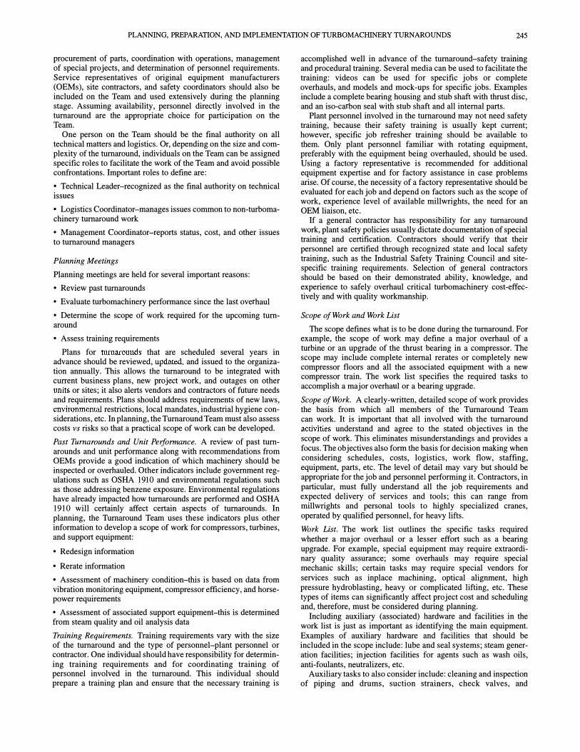
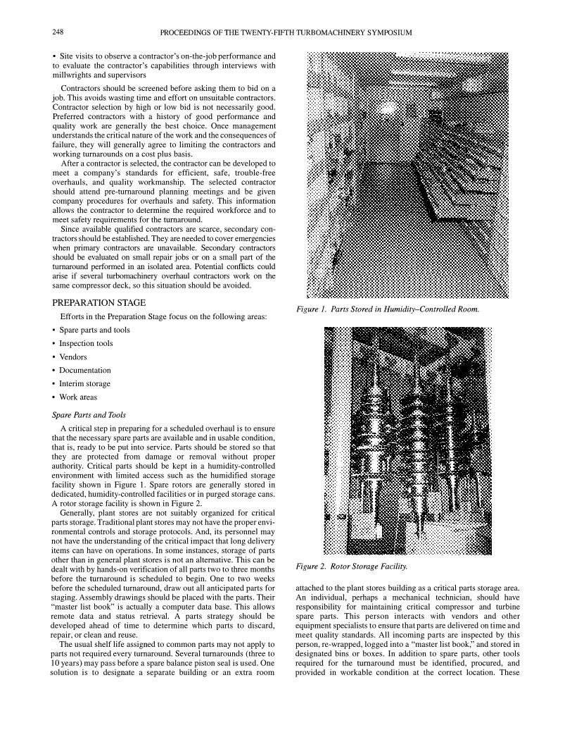
A critical step in preparing for a scheduled overhaul is to ensure that the necessary spare parts are available and in usable condition, that is, ready to be put into service. Parts should be stored so that they are protected from damage or removal without proper authority. Critical parts should be kept in a humidity-controlled environment with limited access such as the humidified storage facility shown in Figure 1. Spare rotors are generally stored in dedicated, humidity-controlled facilities or in purged storage cans. A rotor storage facility is shown in Figure 2.
Generally, plant stores are not suitably organized for critical parts storage. Traditional plant stores may not have the proper environmental controls and storage protocols. And, its personnel may not have the understanding of the critical impact that long delivery items can have on operations. In some instances, storage of parts other than in general plant stores is not an alternative. This can be dealt with by hands-on verification of all parts two to three months before the turnaround is scheduled to begin. One to two weeks before the scheduled turnaround, draw out all anticipated parts for staging. Assembly drawings should be placed with the parts. Their "master list book" is actually a computer data base. This allows remote data and status retrieval. A parts strategy should be developed ahead of time to determine which parts to discard, repair, or clean and reuse.
The usual shelf life assigued to common parts may not apply to parts not required every turnaround. Several turnarounds (three to 10 years) may pass before a spare balance piston seal is used. One solution is to desiguate a separate building or an extra room
Figure 1. Parts Stored in Humidity-Controlled Room.
Figure 2. Rotor Storage Facility.
attached to the plant stores building as a critical parts storage area. An individual, perhaps a mechanical technician, should have responsibility for maintaining critical compressor and turbine spare parts. This person interacts with vendors and other equipment specialists to ensure that parts are delivered on time and meet quality standards. All incoming parts are inspected by this person, re-wrapped, logged into a "master list book," and stored in designated bins or boxes. In addition to spare parts, other tools required for the turnaround must be identified, procured, and provided in workable condition at the correct location. These

PLANNING, PREPARATION, AND IMPLEMENTATION OF TURBOMACHINERY TURNAROUNDS 249
include everything from standard wrenches, malls, and lifting slings to specialized spanner wrenches, metric tools, hydraulic wrenches, lapping devices, and special lifting devices. Necessary mill supplies must also be procured and ready for the turnaround.
Inspection Tools
Quality assurance of incoming parts should be verified. Special inspection tools such as optical flats and micrometers should be available for this purpose. A complete set of drawings should also be available. This is where relationships with the OEMs are important.
Inspections should include: visual inspections (storage preparation, dents, corrosion, part number), dimensional inspections (critical dimensions, surface finish), and inspections using nondestructive testing (NDT) techniques (x-ray, MPI, PMI).
Vendors
The quality assurance/quality control (QA/QC) strategy should define what shop work needs to be covered, the necessary procedures, when the critical work phases will occur, and the appropriate QA/QC methods and documentation. These vary with specific job requirements and available resources. Machinery experience, gained over several years, should enable a vendor to accomplish special tasks such as seal repair, rotor balance, and coatings.
Documentation
Each machine should have a complete, current set of overhaul procedures including disassembly and assembly instructions, and clearance sheets containing correct overhaul tolerances for each assembly check on the unit. A sample data sheet is shown in Table 2. Special procedures should be available for field machining, cleaning methods/materials, shipping preparation requirements, bearing, seal, coupling, alignment, solo, overspeed, etc. The procedures should identify special issues (causes of excessive buffer gas usage, seal oil ingestion, efficiency loss), and past disassembly/assembly problem areas such as galled studs, split line sealing, off-center fits, and internal bolting.
Table 2. Data Sheet for Compressor Clearances.
COMPRESSOR CLEARANCES
Journal Bearings East West
Bearing Crush T hrust Bearing Axial Float T hrust Disc Run-out lso Seal Outboard Sleeve lso Seal Carbon Ring lso Seal Labyrinth Balance Piston Seal All Shaft Sleeve Labyrinths Impeller Seals
1 Stage "AC" 2 Stage "A" 3 Stage "C" 4 Stage "E"
Coupling Hub Run-out Coupling Spacer Gap Turbine Side Hub Gap Gear Side Hub Draw - Turbine End Hub Draw - Gear End
0.003" 0.0043" 0.003" 0.0043" 0.001" 0.002" 0.010" 0.012" 0.000" 0.0005"
0.0025" 0.0035" 0.012" 0.014" 0.008" 0.010" 0.009" 0.013" 0.029" 0.040"
0.038" 0.060" 0.036" 0.057" 0.035" 0.057" 0.035" 0.055" 0.000" - 0.001, 6.440" (+/-) 0.010" 6.440" (+/-) 0.010" 0.070" (+/-) 0.001" 0.065" (+/-) 0.001"
Other essential items to include for documentation purposes:
• Checklists for documenting ("as found" or "as left") disassembly and reinstallation of parts
• Shutdown logs
• Cameras for taking photographs and videos
Videotapes can play a dual role-documenting overhauls and serving as training films. Videos are also valuable for documenting horoscope inspections of associated piping and compressors or turbines that are not opened.
Data books should be prepared with organizational charts, phone lists, MSDS sheets for chemicals, schedule, special attention items, parts dispositions, personal protective equipment (PPE) precautions, work lists, procedures, data/calculation sheets, alignment plots/history, and note pages.
Interim Storage
How parts are handled depends on the parts strategy. Some type of storage container should be available for storing parts from disassembled machines and the special tools used in machinery overhaul. For example, waterproof boxes with lids and locks could be used to store seals, bearings, and couplings removed from machinery along with special customized tools, dowel pins, and other miscellaneous mill supplies. These boxes should be clearly labeled for their proposed contents and placed in locations where they can be easily accessed when needed.
Wooden boxes with partitions can be used for items such as bearings, seals, couplings, and instrumentation. Metal boxes can be used for heavier items, such as portapowers, guide rods, and mill supplies. Larger boxes on rollers are good for storing special, large tools such as hydraulic fit couplings, thrust disc removal and installation tools, and hydraulic tensioning tools for split line bolting. These boxes should also include necessary drawings, data sheets, or other documentation to ensure correct assembly. A shutdown box shown in Figure 3 is a good example of a storage container. A supply of clear plastic bags with drawstrings is a convenient way to store small parts, bolts, nuts, etc. and should be included in the box. These bags should be properly labeled as the components are removed and stored.
Figure 3. Shutdown Boxes.
The need for rotor stands is often overlooked. These should be designed to handle the rotors both on the site and in transit. The design should feature soft, clean supports for the bearing or seal areas and clamping devices for keeping the rotor on the stand during transit.
Work Areas
During any unit outage, considerable congestion occurs around compressor decks. This congestion can be minimized by using

250 PROCEEDINGS OF THE TWENTY-FIFTH TURBOMACHINERY SYMPOSIUM
remote areas for cleanup and repair of large compressor parts such as compressor top half and diaphragms. When necessary, these areas should be designed to have lighting and spill containment for round-the-clock cleanup. Equipment to handle the larger compressor and turbine parts should be identified in the scope review with overhaul personnel. The size of the overhaul and the availability of plant personnel or contractors, may determine who furnishes the tools and equipment for emergency overhauls. All scheduled outages must follow a well-defined scope.
Generally, smaller parts such as bearings and seals are brought from the deck and refurbished in a clean work area adjoining the parts storage facility. These parts should be transported and stored in boxes, which are designed specifically for them, to prevent damage during handling. Each group should be assigned a separate assembly area which serves a dual purpose: storage of personal protective equipment (lockers) and a place to conduct meetings and assign jobs. Access to the compressor floor should be limited to those who work in that area.
A tool and parts storage area should be established on or very near the compressor deck. This should be a supervised area to minimize the occurrence of misplaced or lost tools. A special assembly area should be assigned to technical assistants. This gives the person in charge of the turnaround a place to leave messages for shift personnel, and discuss turnover issues with the next shift and other interested personnel.
Work areas/locations should be planned as soon as the scope of work is defined. This allows adequate time to reserve space for laydown areas and define transportation, lifting, rigging, and crane requirements for integration with the rest of the turnaround.
Suggested enhancements to work areas on some compressor decks might include:
• A roof over the deck for work during inclement weather
• An overhead crane, and in some cases two cranes, large enough to handle the heaviest part such as the casing top half
• Davits and chain falls for working bearings, seals, couplings, etc.
• A tool room on the deck itself, if space is available (Figure 4)
• Work benches with vises and a grinder
• Designated areas for shutdown boxes on a compressor floor (Figure 5)
• Dedicated portable air compressor(s) for supplying the compressor decks, remote overhaul areas, and cleanup area with adequate air supply
• Floor grating decked with plywood to keep parts or tools from falling through if dropped
Figure 4. Tool Room Area During Turnaround.
Figure 5. Designated Area for Shutdown Boxes at Left.
IMPLEMENTATION PHASE
If the planning and preparation stages of the Pre-Turnaround Phase are effectively executed, the implementation or performance of the scope-of-work should go smoothly. Several areas which deserve special attention for continuity are:
• Personnel coverage
• Storage of removed parts
• Lifting and support devices
• Documentation of daily activities
Personnel Coverage
Experienced personnel should be available at all times and should have access to the correct required information. One way to accomplish this is to designate one person (a site turbomachinery specialist or an OEM factory representative) in charge of the turnaround. This allows issues to be resolved promptly and work to be performed efficiently. The person should be on the compressor floor most of the time.
Another method generally used for large jobs is to define roles and responsibilities using a "manning plan" based on tasks to be accomplished. The plan is shown in a block diagram organizational chart where each block denotes a necessary position with a job description. Suggested key roles are:
• Machinery Manager-reports to the Turnaround Management Team and is responsible for the cost schedule and resource coordination
• Lead Engineer-responsible for resolution of technical problems, consults with deck engineers, and handles miscellaneous issues impacting the overall job flow
• Planner-responsible for execution leadership, progress/cost tracking, interdiscipline coordination, and logistical coordination with the main turnaround of cranes, scaffolds, etc.
PLANNING, PREPARATION, AND IMPLEMENTATION OF TURBOMACHINERY TURNAROUNDS 251
• Machinery Contractor Coordinator-performs tasks similar to the planner, but focuses on contractor resources
• Deck Engineer-responsible for job QA, technical problem definition/solution, documentation, and photos.
• Machinery Contractor Supervisor/Foreman-responsible for detailed job planning and execution
• OEM Representatives responsible for technical consulting and factory liaison
Storage of Removed Parts
Parts removed from machines during a turnaround should be marked with the name of the machine and its location, and stored in designated boxes. If the parts are to be reused, care must be taken during cleanup so identification markings are not lost. If ·
parts are to be replaced, old parts should be stored until after startup for failure analysis and an assessment for possible rebuilding.
Lifting and Support Devices
Only experienced and certified rigging or hoisting personnel should be used for major lifts such as top case halves, rotors, and diaphragms. Light lifting with davits and chain hoist should be available to everyone. It is important that the correct slings, shackles, turnbuckles, and spreade bars be provided in suitable condition.
Lifting and rigging plans may be developed showing bills of material (for example, shackles, slings, and turnbuckles) and rigging drawings may be made for each major lift. These drawings can be updated after the turnaround.
Special swivel fixtures are sometimes used to facilitate flipping of top halves. The choice of top half support methods and materials (cribbing or special stands) should be determined through development of a detailed plan.
Documentation of Daily Activities
Documentation should include data sheets, shift logs, photographs, and videotapes. All data sheets must be promptly completed with as-found conditions and dimensions, plus as-built data. Shift logs, coordinated by a designated individual, should be kept current by supervisors and consultants. Cameras and videorecorders should be used as much as possible for documenting the turnaround. These provide valuable information for future reference and training.
POST TURNAROUND PHASE
Important activities that should take place during the Post Turnaround Phase include:
• Replenishing, upgrading, and repairing parts
• Documenting the turnaround
• Following up on work lists
• Critiquing and debriefing
Replenishing, Upgrading, and Repairing Parts
Sometimes wear parts such as seals, bearing pads, labyrinths, and bushings are damaged beyond repair and their replacement is necessary. Very costly items such as rotors, couplings, diaphragms, nozzles, valves, and bearing assemblies, are normally repaired to first-class condition and returned to appropriate storage. A planned "proving-out" period should be scheduled when upgraded components are installed. The required data is gathered during this period for assessing whether the upgrade was successful. If the upgrade was successful, affected spare parts can also be upgraded.
Documenting the Turnaround
Turnaround documentation should include summaries of the completed work, findings, problem areas, and recommendations for the next turnaround. Pre-turnaround and post-turnaround operating data that is representative of the machine's mechanical and aerodynamic performance should also be filed for historical purposes. This should be done as soon after the turnaround as possible while memories are still fresh, and while people are still available. Photos, disassembly and reassembly data sheets, and original logs should be filed. Photos can be invaluable in planning future work. It is recommended that the photo negatives be kept in a different place than the prints, so prints can be made if the original file containing the prints is lost.
Following Up on Work Lists
There are usually a few followup items( oil leaks, pipe braces, etc.) that occur after systems and machines are commissioned. This may take place several days or weeks after the major work is completed. The machinery contractor personnel will no longer be present. Therefore, it is important to plan for someone, either plant personnel or a few of the contractor millwrights, to be available with the proper tools to handle these items.
Critiquing and Debriefing
A post-turnaround meeting should be scheduled before nonsite personnel leave. The meeting agenda should include:
• An assessment of what worked and what did not work well
• A strategy for capitalizing on turnaround strengths and weaknesses (learnings)
In addition, a meeting report should be distributed to all personnel associated with the turnaround.

252 PROCEEDINGS OF THE TWENTY-FIFTH TURBO MACHINERY SYMPOSIUM