
PLANNING GUIDELINE FOR FUEL CELL BACK-UP POWER …
40
UNINTERRUPTIBLE POWER SUPPLY (UPS) AND EMERGENCY POWER SYSTEMS (EPS) WITH FUEL CELLS PLANNING GUIDELINE FOR FUEL CELL BACK-UP POWER SUPPLIES www.cleanpowernet.de Benedikt Eska Marcel Corneille No local emissions No noise pollution No vibrations Long bridging time Long life High reliability Stationary or mobile Modular and expandable
Transcript of PLANNING GUIDELINE FOR FUEL CELL BACK-UP POWER …

UNINTERRUPTIBLE POWER SUPPLY (UPS) AND EMERGENCY POWER SYSTEMS (EPS) WITH FUEL CELLS
PLANNING GUIDELINE FOR FUEL CELL BACK-UP POWER SUPPLIES
www.cleanpowernet.de
Benedikt EskaMarcel Corneille
No local emissions
No noise pollution
No vibrations
Long bridging time
Long life
High reliability
Stationary or mobile
Modular and expandable

Prepared for NOW GmbH – National Organisation Hydrogen and Fuel Cell TechnologyFasanenstrasse 5, 10623 Berlin, Germany
Technical description Technology Management SK Münchener Straße 35a85748 Garching
AuthorsBenedikt EskaMarcel Corneille
Published byClean Power Net (CPN)
© Clean Power Net 2018

UNINTERRUPTIBLE POWER SUPPLY (UPS) AND EMERGENCY POWER SYSTEMS (EPS) WITH FUEL CELLS
PLANNING GUIDELINE FOR FUEL CELL BACK-UP POWER SUPPLIES
Benedikt EskaMarcel Corneille

Preamble
Two of the 21st century’s core tasks are closely linked: the digitalisation of society and the energy transition. Digitalization requires a reliable supply of electricity in the event of power failures and the energy transition necessitates the use of alternative technologies such as fuel cells. Diesel generators are increasingly being replaced by fuel cell systems as they offer technical, ecological and economic benefits. The provision of back-up power supplies with fuel cells, whether as an uninterruptible power supply (UPS) or emergency power supply system, is becoming increasingly important, especially in the areas of the following critical infrastructures:
• Emergency services BOS digital radio and mobile radio (base stations)
• Transmission and distribution network operations (substations, water treatment)
• Traffic control technology (railway signal boxes, signalling systems, airport and air traffic security systems)
• Security technology (construction site monitoring, inspection and test stations)
• IT infrastructure (protection of data centres)
• Healthcare (hospitals, mobile health stations)
• Industrial production (operational control technology)
This guideline is intended to serve as a practical aid for planning and consulting engineers, and to facilitate their entry into the technology as well as the planning and approval process for the construction and operation of fuel cell facilities. The “Technical Description” chapter provides a concise overview of the planning, installation, commissioning and operation of fuel cell back-up power supplies. A checklist is included in the appendix to help simplify the planning process. Furthermore, the planning guide also contains:
• A depiction of the advantages that fuel cells offer compared to diesel emergency power systems
• An overview of different fuel cell types and solutions
• A closer look at grid-connected and off-grid systems

Up-to-date information on funding support for fuel cell systems can be found on the NOW GmbH (National Organisation Hydrogen and Fuel Cell Technology) website: www.now-gmbh.de.
Information on suppliers of fuel cell solutions, their performance profiles and relevant contact details can be found on the Clean Power Net (CPN) website:www.cleanpowernet.de.
Wolfgang Axthammer,Managing Director of NOW GmbH and Clean Power Net Project Manager.

Planning Guideline for Fuel Cell Back-up Power Supplies
6
Table of contents 1 Background and Motivation ............................................................................................................ 7
2 Introduction ..................................................................................................................................... 8
2.1 Foreword by the authors ......................................................................................................... 8
2.2 Guideline structure .................................................................................................................. 9
Technical Description ............................................................................................................................ 10
3 Overview........................................................................................................................................ 11
3.1 Fuel cell technology – technical background ........................................................................ 11
3.2 Advantages of fuel cells in comparison to battery and diesel back-up power systems ........ 14
3.3 Typical applications ............................................................................................................... 18
4 Planning ......................................................................................................................................... 20
4.1 Calculation of power output ................................................................................................. 21
4.2 Runtime of the back-up power supply system and dimensioning of the fuel storage tanks 22
4.3 Electrical integration .............................................................................................................. 24
4.4 Fuel cell and fuel selection .................................................................................................... 27
4.5 Safety concept ....................................................................................................................... 27
4.6 System description and installation concept ......................................................................... 28
5 Installation ..................................................................................................................................... 28
5.1 Indoor and Outdoor .............................................................................................................. 28
5.2 Construction site logistics ...................................................................................................... 28
6 Commissioning .............................................................................................................................. 29
7 Operation....................................................................................................................................... 29
7.1 Application Case .................................................................................................................... 29
7.2 Test operation ........................................................................................................................ 29
7.3 Maintenance & servicing ....................................................................................................... 30
7.4 Fuel logistics .......................................................................................................................... 30
8 Technical Description Summary .................................................................................................... 31
A.1 List of abbreviations .............................................................................................................. 32
A.2 Glossary ................................................................................................................................. 33
A.3 Dimensioning ......................................................................................................................... 34
A.4 List of figures ......................................................................................................................... 38
A.5 Authors .................................................................................................................................. 39

Planning Guideline for Fuel Cell Back-up Power Supplies
7
1 Background and Motivation Some electrical equipment and systems have such importance or are so critical that power failures
could result in either a danger to life and limb or major economic damage. Such facilities, also known
as critical infrastructures, are typically equipped with a so-called back-up power supply, which takes
over the continued supply on a temporary and transitional basis if the regular power supply fails.
Back-up power supply (BPS) systems are generally categorised as being either uninterruptible power
supply (UPS) or emergency power supply (EPS) systems.
In order to be able to bridge longer periods of power failures, the mostly battery-operated UPS
systems are typically extended by EPS systems. Previously, diesel generators with appropriately
dimensioned diesel tanks were typically used on site. A high degree of awareness among buyers,
project developers and planners as well as established sales structures have so far produced a strong
affinity to diesel-based EPS systems. Moreover, the generally perceived widespread use of diesel EPS
systems often (subconsciously) leads to the conclusion that diesel technology is highly suitable.
However, the technology-related disadvantages for stand-by operation, which are very pronounced
with EPS systems in stable power grids, are largely overlooked or at least underestimated.
Degradation in the fuel and engine oil as well as corrosion in the cooling water circuit cause the diesel
unit to age noticeably, especially in stand-by mode, thereby having a dramatic impact on the system's
availability when it matters.
Conversely, a whole series of favourable characteristics make fuel cell technology very attractive for
deployment for back-up power supplies:
Fast and safe start-up in the event of a power failure
Low maintenance requirements and minimal aging tendency in stand-by mode
Power output can be regulated over a wide range while maintaining a high degree of
efficiency
No degradation of fuels
Fuel cell technology can particularly leverage its technological strengths where high availability or
stringent environmental requirements are required.
Several projects funded by the National Innovation Programme Hydrogen and Fuel Cell Technology
(NIP) have already proven their viability and suitability for everyday use. Although such solutions are
now commercially available, demand is still very sluggish. This is most likely due to the technology
still being new and that the approval processes and planning documents are not yet standardised nor
generally well-known.
This guideline is intended to close existing gaps in knowledge by providing information and specific
recommendations for action and thus reduce hurdles and inhibitions towards the use of this
technology. It is intended to encourage and provide practical support for the increased use of
innovative fuel cell technology in future BPS projects, thus contributing to the achievement of
environmental and climate goals. The aim is to simplify the conceptual development of new fuel cell
(FC) projects for planners.

Planning Guideline for Fuel Cell Back-up Power Supplies
8
2 Introduction 2.1 Foreword by the authors This planning and approval guideline, hereinafter referred to as the “guideline”, is especially aimed at
experts with experience in the planning, construction and operation of conventional back-up power
supplies, with an interest in fuel cell solutions.
The guideline deals with the special qualities of different fuel cell types and solutions in a concise
manner. It examines grid-connected systems such as uninterruptible power supply (UPS) and
emergency power supply (EPS) systems as well as off-grid (stand-alone) systems. In this sense, the
umbrella term of “back-up power supplies” (BPS) is defined for the guideline.
Figure 2-1: Distinction between BPS systems in grid connected and off-grid systems
The guideline draws on experience gained in recent years in the planning, construction and operation
of several hundred FC BPS systems, and, in the small power range below 1 kW, several thousand FC
solutions.
The guideline is to be regarded as an aid in the planning of FC BPS systems. For detailed planning,
please refer to the corresponding standards and the relevant technical literature.

Planning Guideline for Fuel Cell Back-up Power Supplies
9
2.2 Guideline structure
Figure 2-2: Overview of the planning guideline structure
The different tasks of those involved in a project are summarized in Table 2-1. All parties concerned
should develop a basic understanding of the legal framework in order to ensure the realisation of a
safe plant. A participant can also have several roles in terms of content. For example, the future
operator can also be responsible for planning the system.
Following the transfer of risk, the overall responsibility for the finished plant always formally lies with
the operator of the plant, who may be supported by a service provider, e.g. for maintenance. In this
table, the installer also subsumes the issues of the hardware manufacturers with regard to the legal
aspects.
Table 2-1: Involved parties and their tasks
Who Tasks Cross references
Planer Technical design, safety requirements in consultation with the operator, documentation
4
Installer Construction of the plant, product safety, planning permission, initial commissioning, documentation
5 6
Operator Operation, maintenance & repairs, fuel logistics, operational safety, documentation
6 7

Planning Guideline for Fuel Cell Back-up Power Supplies
10
Technical Description

Planning Guideline for Fuel Cell Back-up Power Supplies
11
3 Overview 3.1 Fuel cell technology – technical background In general, fuel cells convert the chemical energy of a fuel directly into electricity (and heat) via an
electrochemical process. Depending on the fuel, this conversion is emission-free and does not
produce any particulate matter, unlike combustion engines.
A fuel cell is a source of direct current (DC). Different types of fuel cells are differentiated according to
the electrolytes used (as with batteries) and the fuels used. Depending on the fuel cell type, different
fuels such as hydrogen, methanol or liquid gas (propane and butane – LPG) can be deployed.
The type of fuel cell and the fuel itself together constitute a unit and cannot be regarded in
isolation.
The actual conversion process takes place in a single cell in which fuel and air is supplied and is scaled
according to the area of the cell. The larger the area, the higher the current. Depending on the
operating point, each cell supplies a specific voltage. A typical operating window for PEM FCs is
between 0.8 and 0.6 volts per cell. In order to achieve sufficient voltage, the cells are stacked,
i.e. connected electrically in series, to form a fuel cell stack.
The fuel cell stack must be supplied with fuel and air. The waste heat produced must also be
dissipated either via an air or water cooling process. To this end, components such as valves, sensors
and fans are connected together with the fuel cell stack to form a fuel cell system. The auxiliary units
are often referred to as peripherals or Balance-of-Plant (BoP).
Figure 3-1: Schematic diagram of a fuel cell system

Planning Guideline for Fuel Cell Back-up Power Supplies
12
The fuel itself is stored in corresponding tanks and is pumped to the FC system via supply lines.
Depending on the fuel used, different storage vessels are deployed. The maximum operating time of
the entire system is determined by the size of these vessels.
Depending on the demands required of the FC back-up power supply system, this typically consists of
the following main components:
Fuel cell system (incl. cooling system and compressor-expander unit, if required)
Fuel storage and, if necessary, processing
Where necessary, inverters
Control unit
Battery to support the voltage during the switch-on process
Housing with required heating/air conditioning, if applicable
Figure 3-2: Schematic diagram of a FC back-power supply system
Depending on the individual manufacturer concept, the main components can be combined in one or
more modules, usually as a 19-inch rack. Many manufacturers follow a modular approach and can
therefore vary the performance offered in certain bandwidths or provide a degree of redundancy.
The systems available on the market have preferred areas of application due to their operational
characteristics. The following values are approximate and differ depending on the provider and
configuration. All configurations considered contain a support battery, which varies in capacity
depending on the application and system.

Planning Guideline for Fuel Cell Back-up Power Supplies
13
Figure 3-3: Typical characteristics of commercially available fuel cell systems
It should be noted that not all PEM FCs are suitable when methanol is used.

Planning Guideline for Fuel Cell Back-up Power Supplies
14
3.2 Advantages of fuel cells in comparison to battery and diesel back-up power systems
Fuel cell back-up power supply systems combine the advantages of battery and diesel solutions.
Depending on the fuel, they operate with low or zero emissions like a battery, but offer running times
like diesel engines. In addition, there is no technical limitation as to the capacity or tank size to be
installed. The most important functional criterion – availability in the event of an emergency
(72 hours are usually specified) – has already been successfully demonstrated in several hundred
installed systems throughout Germany.
The fuel cell offers decisive advantages at low to medium outputs and relatively long
running/bridging times while simultaneously achieving high availability. In a total-cost-of-ownership
(TCO) analysis, compared to a diesel or battery emergency power supply (EPS) system, the fuel cell
achieves a break-even after just a few years due to the lower maintenance costs.
Table 3-1 compares various criteria:
Figure 3-4: Fuel cells are particularly suitable for long bridging times

Planning Guideline for Fuel Cell Back-up Power Supplies
15
Criteria Battery EPS Diesel EPS Fuel cell BPS
TCO
Switch-on availability
Service Life
Batteries age even in stand-by. The condition of individual cells can only be estimated with great effort. For this reason, when deployed in critical applications, the batteries used are exchanged each 2 years, for example.
Unproblematic with proper maintenance
Fuel cells in FC BPS systems are usually manufactured for 4,000 operating hours. FCs for continuous operation can also reach 60,000 hours. Manufacturers anticipate a system service life of 15–20 years.
Stand-by ageing
Maintenance & service
Maintenance-free
High-maintenance
Maintenance-free or low-maintenance depending on manufacturer and application.
Exhaust gases
Zero emissions
NOx
CO2
CO
Fine particulate matter
Zero emissions when
operated with hydrogen
CO2 during operation with methanol
Noise
Silent Depending on
enclosure and supplier, typical values 65 dB (A) +/- 10% (7m).
Low noise. Noise is caused by the air intake.
Temperature (with additional measures, if necessary)
Narrow operating window to avoid ageing or loss of battery capacity.
At very low temperatures, pre-heating of the diesel may be necessary.
Depending on the fuel cell type and manufacturer, different temperature windows are specified. If necessary, heaters are used in outdoor cabinets.
Table 3-1: Comparison of a battery or diesel EPS and a FC BPS

Planning Guideline for Fuel Cell Back-up Power Supplies
16
3.2.1 Attributes of the different fuels There are three types of fuel that are suitable for use in the FC back-up power supply (BPS) systems
currently available on the market today: hydrogen, LPG and methanol. Each of these fuels is readily
available in Germany. The attributes of the respective fuels, however, differ significantly in terms of
energy content, storage form and their hazard potential:
Hydrogen is gaseous and is typically stored in compressed gas cylinders with pressures
ranging from 200 to 300 bar. In relation to weight, hydrogen has a very high energy density.
For storage, the weight of the pressurised gas cylinders must be taken into account. Hydrogen
is harmless for the environment and non-toxic for humans.
LPG is gaseous when kept at ambient pressure, but liquid when stored under pressure
(typically at 8 bar in pressurized gas cylinders). It consists of variable proportions of propane
and butane and thus varies slightly in energy density. Like hydrogen, LPG is neither hazardous
to the environment nor toxic.
Methanol is liquid and is stored unpressurised in tank sizes ranging from a few litres to 1 m3.
The environmental properties (slightly hazardous for water) limit its use in sensitive
ecosystems. It should also be noted that methanol is harmful to human health upon direct
contact, albeit to a lesser extent than diesel.
Figure 3-5: Gravimetric energy densities of various fuels
Figure 3-5 compares the energy content of the fuels in relation to their mass (gravimetric energy
density). Based on this value, the required fuel mass can be calculated according to the energy
demand. The energy content related to the volume (volumetric energy density) is more important for
the determination of the required storage size. This depends on the storage media used. Liquid fuels
have clear advantages here, as they require lower storage volume levels.
The fuels differ greatly in their shelf life. In practice, this is particularly important for UPS/EPS systems
and applications with small amounts of operating hours.

Planning Guideline for Fuel Cell Back-up Power Supplies
17
Hydrogen and LPG can be stored indefinitely and may be used permanently for the application.
In the case of methanol, it depends on the material of the storage vessel. Direct methanol FCs
(DMFC) require a high degree of fuel purity. In the case of plastic containers, leaching can occur and
thus lead to reduced maximum storage periods. It is therefore currently recommended not to use the
containers for longer than three years. In most cases, special cartridges are offered which prevent
contact with the methanol and thus rule out any danger to personnel. Thousands of such systems are
already in use, for instance in the leisure sector (motorhomes, boats).
The storage life of diesel without changing the properties is specified as 90 days (DIN EN 590:2017).
It is possible, for example, that the water ratio may change. Moreover, the growth of microorganisms
can lead to the so-called “diesel bug”. Depending on its severity, this can lead to a failure of the diesel
emergency power supply system. For this reason, the diesel fuel must be replaced regularly and, as a
rule, this incurs disposal costs.
Table 3-2: Comparison of different fuel types
→ Further information on the storage systems can be found in section 4.2.
3.2.2 Cost drivers The following factors push up the costs for FC back-up power supply systems and should be
considered in the planning:
The over-dimensioning of the required electrical power. This increases both the investment
for the FC system and for the tank system.
Short tender periods increase the planning risk for the manufacturer or installer. This
increased risk is passed back to the tenderer by means of the price.
Unnecessary redundancy demands.
Insufficiently thought-out safety concepts.
Constellations that have not yet been realized lead to increased engineering costs, for
example:
o Requirements for special housings, e.g. for high resistance classes.
o Use of particular components, e.g. special voltage converters.
The integration into existing software architectures such as for remote maintenance.
By engaging with manufacturers, experts and other operators at an early stage, it is possible to
identify cost drivers during the actual planning phase and thus optimise the calculation of costs.

Planning Guideline for Fuel Cell Back-up Power Supplies
18
3.3 Typical applications The following examples of applications are intended to help illustrate the implementation of a FC
back-up power supply system. The examples do not constitute a recommendation for or against a
particular technology. Examples that have been selected are those that are currently in use in
Germany where more than one hundred of such systems are in operation. A grid-connected
telecommunications solution and an off-grid power supply for gathering operational data will be
presented.
Example 1: FC UPS for a grid-connected mobile telecommunications site
Figure 3-6 shows a hydrogen-powered PEM FC with air-cooled modules of 2.5 kW each. The FC UPS
consists of two outdoor cabinets. One cabinet contains the FC with converter, back-up battery and
control electronics. This cabinet is physically separated from the hydrogen supply.
The hydrogen is housed in its own cabinet and is stored at 300 bar in several 50-litre steel cylinders.
The stored amount of fuel enables a bridging time of at least 72 hours.
The cylinders are divided into two supply lines of different sizes, which are automatically switched
over. In this way, only individual cylinders are operated during instances of routine, automatic test
operation, thus ensuring the required bridging time is maintained over the larger supply line
(see also Section 4.2).
Figure 3-6: Example of a hydrogen-powered FC UPS

Planning Guideline for Fuel Cell Back-up Power Supplies
19
The system features remote access and can also be checked via remote maintenance. This avoids
journeys needing to be made to isolated locations.
Example 2: FC back-up power supply system for the off-grid supply of power
A PV system charges a battery bank here. In addition, the unit is connected to a FC system, which
ensures the supply of energy in unfavourable weather conditions. The system is housed in a small
outdoor cabinet (Figure 3-7).
A DMFC with a continuous output of approx. 100 W is in use. Together, the two methanol fuel
cartridges contain 56 litres. In this hybrid configuration and with the applied load, continuous
operation is possible for one year. During this time, the FC system starts up independently as
required. The system is maintenance-free except for replacing fuel cartridges. When these are
exchanged, contact with the methanol is ruled out.
Figure 3-7: Example of a methanol-powered FC back-up power supply system

Planning Guideline for Fuel Cell Back-up Power Supplies
20
4 Planning
A FC back-up power supply (BPS) system should not be treated any differently from a conventional
BPS system, in most respects. As with all BPS systems, the most important criterion is the electrical
load of the system, and the electrical integration of the BPS system is the critical path to
implementation.
When selecting the right FC type – and therefore also the fuel type – various constraints need to be
accounted for. The selection process is usually carried out in an iterative manner.
Figure 4-1: Selecting the fuel cell and the corresponding fuel
Note:
The characteristics of a fuel cell can be compared to a constantly charged battery.
The fuel cell also has a corresponding current-voltage characteristic (I-V curve).
But in contrast to the battery, there is no discharge curve over time, but the FC
remains load-dependent at a specific operating point of the I-V curve.

Planning Guideline for Fuel Cell Back-up Power Supplies
21
4.1 Calculation of power output In principle, FC back-up power supply (BPS) systems can be dimensioned to handle any required
capacity. Its modularity allows planners to adjust the performance as demanded.
It is generally recommended that not the peak power loads but rather the average power of the loads
over time (average power output) be chiefly considered when selecting the appropriate FC output
capacity. In the case of diesel emergency power supply (EPS) systems, due to the direct coupling of
diesel engine and generator, both components must be specially dimensioned to cope with any
power or torque peaks that may occur. Meanwhile, with FC BPS systems, it is the voltage converter
that must be able to handle the required peak loads and can use the support of the battery on the
primary side, which is why the FC does not need to be dimensioned for peak performance.
With FC systems, investment costs usually scale-up significantly more sharply to peak performance
than with other BPS system types. By conducting a detailed analysis of the energy consumers that
need to be supplied in the event of an emergency power supply situation, investment costs can be
minimised and TCO potentials optimised.
As with other BPS system types, the analysis of energy consumers needs to address the following
typical questions:
Number and type of consumers?
Minimum supply duration?
Are any motorised three-phase
consumers to be supplied?
Peak load (starting currents?) and
average load?
Which consumers are to be supplied in
the event of an emergency power
supply situation and to which phases
are these connected?
Is redundancy required?
Some operators decide to measure the actual electricity demand at the site that is to be supplied. It is
not uncommon to find that the calculated rated load is up to three times higher than the actual
demand.
For the dimensioning of the electrical system, the difference between kVA and kW must be regarded
(see also Appendix A.3.1 for more details). Formally, it is the same physical unit, but when
interpreting it, it should be noted that in common language use kW is only the real power, and kVA
the apparent power (real power plus reactive power). In a DC voltage network and with pure ohmic
loads, both are identical. Fuel cells are DC voltage sources and the real power is always given in kW.
If electric machines, such as electric motors, need to be supplied with power, high starting currents
must also be accounted for. As a result, the load can briefly rise to about 3 times the nominal load.
This peak load must be covered by the BPS system (see Figure 4-2). In the case of FC BPS systems, this
is typically taken up by the back-up battery – and the average power output is used to determine the
dimensioning of the FC system.
→ Further information in Appendix A.3.1 and A.3.2.

Planning Guideline for Fuel Cell Back-up Power Supplies
22
Figure 4-2: Schematic representation of a load curve and the resulting dimensioning of FC and diesel back-up power supply systems.
4.2 Runtime of the back-up power supply system and dimensioning of the fuel storage tanks
4.2.1 Determining the storage capacity on the basis of the calculated performance The FC system’s storage size determines the maximum runtime of the system and can be established
on the basis of the calculated average power output.
The required storage size can be calculated from:
The desired runtime of the system, and
The fuel cell’s consumption at the desired output level. Details of FC consumption can be
found in the specifications provided by the manufacturer.
Storage size = runtime of the system x FC consumption level at medium output capacity
Typical storage sizes for common systems and power classes are shown in Table 4-1. The calculation
basis can be found in Appendix A.3.3.
It should be noted that the calculated runtimes represent the minimum runtimes to be attained. As a
rule, however, the actual achievable runtime will be significantly higher, since a worst-case scenario
with maximum load demands was used as a basis for calculation.

Planning Guideline for Fuel Cell Back-up Power Supplies
23
FC system Fuel Average load
Desired Runtime
FC system consumption at average load
Required storage size and quantity
PEM Hydrogen 1 kW 24 h 0.06 kg/h 1.4
2 kg cylinder
DMFC Methanol (direct)
0.1 kW 24 h 0.09 l/h 2.2
1 l canister
SOFC LPG 1 kW 24 h 0.20 kg/h 4.8
1 kg cylinder
Table 4-1: Calculation of tank volumes for various example FC systems
A more detailed calculation tool for estimating the storage quantity depending on FC type, operating
time and load is included in the guideline checklist (Appendix A.5).
4.2.2 Storage for test operations Some back-up power supply (BPS) systems, in particular uninterruptible power supply (UPS) systems
for critical consumers, perform regular self-tests. The dimensioning of the storage medium should
take such test operations into account. For example, a two-stage tank system can be used, which
includes a smaller tank for test operations and a larger tank for emergency operations. This means
that the fill level of the emergency storage tank is not affected by regular test operations. Especially
in the case of gas storage facilities, this prevents the premature replacement of partially depleted
cylinders. The storage for the test operations can then be refilled or replaced as required. The
dimensioning is determined by the average required output during test operations.
Table 4-2 shows an example of the dimensioning for test operation and for BPS system operation
using a hydrogen PEM. The test should be started every 14 days for 15 minutes. The storage tank
should be sufficient for a project duration of 5 years with an average load of 500 W in test operation.
One 50 l pressurised gas cylinder (300 bar) is sufficient for this purpose.
Storage tank application Average load
Desired Runtime
Overall system consumption
Required storage size and quantity
Test operation 0.5 kW 0.25 h 0.03 kg/h 0.98
1
kg cylinder each 5 y.
Back-up power supply 2 kW 72 h 0.12 kg/h 8.6
9
kg cyl. per deploym.
Table 4-2: Dimensioning of the storage tanks for test operations and for BPS system operation using the example of a hydrogen PEM
→ Further information in Appendix A.3.3

Planning Guideline for Fuel Cell Back-up Power Supplies
24
4.3 Electrical integration
4.3.1 General information All applicable guidelines regarding the installation and operation of back-up power supplies must also
be observed for fuel cell types, including:
The separation of all phases
No feeding back of power into the grid
The avoidance of parallel mains power operation during trial runs
During integration, it should also be noted that it must be possible to disconnect all system
components – including the FC system – from the power supply at the main distribution board. This
shutdown capability is necessary so that all work can be carried out in accordance with the applicable
standards and directives.
Close consultation with the manufacturers is recommended for optimal integration.
4.3.2 Redundancy and modularity
Reliability and availability are crucial for back-up power supply (BPS) systems. Both can be enhanced
by means of redundant subsystems. Whether a redundant design makes sense depends on the user
requirements. Redundancy needs should always be considered from the perspective of the entire
chain of dependencies. If, for example, in Case IV as shown Figure 4-3, the necessary toggle switch is
only of a simple design and all downstream components (such as converter, contactors, heating/air
conditioning) are also simple, this part of the system becomes the weakest link in the chain. It only
makes sense to address this issue by taking a holistic approach, including consideration of the failure
probabilities of individual components.
In most systems, the FC BPS is already the redundant system for the grid connection. Nevertheless, FC
systems are often modular in design (Case II of Figure 4-3). Apart from the additional redundancy,
further advantages result from a modular design depending on the application:
Figure 4-3: Varying modular concepts

Planning Guideline for Fuel Cell Back-up Power Supplies
25
If the load is increased by new installations on the consumption side, this can be compensated by
adding another FC module. For this purpose, the infrastructure, such as housing size or air supply,
may have to be designed for the higher output during system planning. Consequently, future
additional overheads for safety due to subsequent extensions – and thus costs for the FC system –
can already be reduced conceptually.
Modular concepts also provide advantages for consumers with load profiles that vary greatly over
time, such as the case with the operation of a heating system in summer and winter. If two modules
are used in this example, then only one module needs to be operated in summer, which avoids
extreme partial load operation and improves system efficiency. The switching of individual modules
takes place automatically, depending on the applied load.
4.3.3 Examples of possible FC back-up power supply integration The following illustrations are greatly simplified and are only intended to provide a general overview
of possible configurations in grid-connected cases.
Figure 4-4 shows a FC back-up power supply (BPS) system with a DC/AC converter. As with a diesel
emergency power supply (EPS) system, a switch is required here. The start sequence of the FC BPS
can, for example, be initiated via a phase monitor. The battery supports the voltage during the
starting cycle and ensures an interruption-free supply of power.
Figure 4-4: Example of a circuit configuration for supplying AC and DC loads

Planning Guideline for Fuel Cell Back-up Power Supplies
26
Should only DC consumers require power supply, e.g. in telecommunications applications, a converter
can usually be eliminated and a much simpler concept implemented. The FC system and battery are
then on the DC side, as shown in Figure 4-5.
The actual implementation is dependent, among other things, on the output voltage of the fuel cell.
However, it may also be more economical to use an additional buck-boost converter here.
4.3.4 Note concerning low voltage applications and self-sufficient solutions As with conventional solutions, the topic of electrical integration is simpler if the system is:
Not subject to the Low Voltage Directive as the nominal voltage is less than 75 V DC,
or
Not connected to the grid
In general, the requirements here are geared more towards continuous operation and self-sufficient
solutions. In these cases, the fuel cell usually extends a PV system in order to ensure operational
reliability even during periods of poor weather or in winter. These fuel cells run significantly longer
operating hours and less cyclically than in UPS applications.
4.3.5 Changeover switches Fuel cells must be actively switched on – just like diesel engines. A trigger is required for this. In
uninterruptible power supply systems, this can be, for example, a phase monitor or a power drain on
the back-up battery, which is used to transmit a signal to the FC controller. The signal causes the fuel
cell to start up, which then takes over the supply of power.
If the FC back-up power supply system is to be tested remotely – as is usually the case – special
attention must be paid during wiring to ensure that the network can be safely disconnected and
reconnected. As with diesel-based systems, mains parallel operation or the feeding back into the
mains grid is not permitted.
Figure 4-5: Example of a circuit configuration to supply purely DC consumers

Planning Guideline for Fuel Cell Back-up Power Supplies
27
Suitable changeover switches are available on the market as standard components. However,
experience shows that, depending on the configuration of the entire electrical system, avoidable
errors have repeatedly occurred during switching.
4.3.6 Circuit breakers In the event of a short circuit, it must be ensured that the circuit breakers trip reliably. The necessary
short-circuit current I(t) cannot be provided by the fuel cell alone in all systems. The necessary cut-off
currents can be provided by suitable converters or by batteries connected in parallel.
The planning or tender documents should contain information on the planned circuit breakers or the
required cut-off currents.
Background:
The fact that the short circuit current can in part not be provided by the fuel cell is
due to the necessary tracking of the reaction gases, e.g. air in the fuel cell. The
high currents in the event of a short circuit generally cause the voltage of the fuel
cell to drop briefly, which is a typical shutdown criterion. FC manufacturers usually
use current limiters to avoid this happening.
4.4 Fuel cell and fuel selection Given that many different criteria of the future operator and the planned system are considered
when making the selection, no universal recommendation can be provided for a certain FC-fuel
combination. Moreover, FC manufacturers are constantly developing their products and additional
commercially available solutions are being introduced to the market. Clean Power Net member
manufacturers can provide support and further information in this regard.
Nevertheless, a preselection of FCs and fuels can usually be made on the basis of the required power
and the planned electrical integration.
Should different fuel and FC solutions be shortlisted, it is advisable to evaluate the costs for the
necessary fuel tanks and fuel logistics. To this end, other constraints of the planned installation site
must also be taken into account, including the space that is available for the fuel.
4.5 Safety concept The scope of the measures for occupational and operational safety is not significantly different from
that of conventional diesel or battery back-up power supply systems.
The relevant legal regulations regarding product and operational safety must generally be observed
for all systems.

Planning Guideline for Fuel Cell Back-up Power Supplies
28
4.6 System description and installation concept A detailed description with all delivery interfaces and available information is required for the
implementation of the system. The document should contain at least the following information:
Electrical framework conditions and planned integration
Description of the site, e.g. available space
Further information, e.g., accessibility, remote maintenance, nature reserve status, etc.
The description can be used when communicating with potential suppliers and the planning can be
further refined successively. Clear interfaces (requirements and functional specifications) support
cost-effective implementation.
Detailed planning and installation planning can then be derived from this, just as with conventional
back-up power supply systems.
5 Installation FC back-up power supply systems can generally be installed both indoors and outdoors. A number of
points must be taken into account when setting up a fuel cell system outside, depending on the
prevailing conditions.
5.1 Indoor and Outdoor When installed indoors, it is recommended to protect the FC system against external influences
(e.g. protection against contact) by means of an enclosure. As in the case of battery and diesel
systems, adequate ventilation of the premises must be ensured. Depending on the manufacturer and
system, additional exhaust air may need to be discharged.
When designing the housing for outdoor applications, the weather conditions must be considered.
Sufficient protection against snow, rain and humidity should be taken into account. If the back-up
power supply system is installed in a delicate environment (e.g. nature or water conservation area),
applicable measures for environmentally hazardous fuels must be taken in the event of unintentional
fuel spillages. In the case of liquid fuels such as methanol, this can entail the use of a drip pan, as with
diesel applications. Alternatively, a fuel (and the corresponding system) can be selected which has no
environmentally hazardous properties.
5.2 Construction site logistics The fuel cell does not require any special measures for construction site logistics. This is determined
by the constraints imposed by the weight and dimensions of the largest or heaviest individual system
components.
If installation is to be carried out at remote locations, it is important to provide information regarding
accessibility, such as gradients in mountainous areas or narrow hairpin bends when accessing the
site. This is no different from the case of conventional back-up power supply system installations.
For subsequent fuel logistics purposes, it may make sense to retain any roads that needed to be built
during the construction phase.

Planning Guideline for Fuel Cell Back-up Power Supplies
29
6 Commissioning As with any back-up power supply system installation, special measures must also be observed during
the initial commissioning of the system. Especially in the case of large and complex systems, it is
advisable to have system components that can be removed separately.
In order to ensure correct functionality, functional tests must be carried out on all system
components, in particular safety-relevant functions. This includes, for example:
A leak test of the fuel system
Testing of the switch-over in case of emergency power supply
It may be useful to make advance preparations for the fuel storage tanks. For example, tanks or
cylinders can be flushed and filled at a central warehouse, so that only a leak test will still need to be
carried out on site after installation.
7 Operation
The details of the operation of a FC back-up power supply (BPS) system are explained in the
following, both in the case of general use and in test operation. Furthermore, information on
maintenance and servicing as well as fuel logistics is provided.
7.1 Application Case In the event of a failure of the main power supply, the BPS system back-up battery ensures an
uninterrupted supply of power. As soon as the fuel cell is started and delivers its rated power output,
it takes over the task of supplying power. Other peak loads are again covered by the back-up battery.
Depending on the overall concept, the battery is charged either directly from the FC or only after grid
availability has been restored. The operating or bridging period can be changed as desired by
adjusting the storage size (see section 4.2).
Remote access to the FC BPS system during operation can be useful in order to be able to retrieve
information about the remaining operating time or the residual amount of fuel, as well as to enable a
diagnosis of performance or faults, if necessary.
If changes are made to the system, the average power output during operation and the required
amount of fuel should be verified again.
7.2 Test operation To ensure reliable operation and maintain functionality, automated test runs are typically carried out
on a regular basis. The test runs can, for example, take place at 14-day intervals. During the tests,
individual components of the system are switched on and operated with power from the fuel cell.

Planning Guideline for Fuel Cell Back-up Power Supplies
30
The test operation should cover as wide a range of BPS applications as possible.
Each self-test usually lasts a few minutes. The fuel consumption for the test operation can be
estimated from the considerations outlined in section 4.2.
The intervals and the duration of the self-tests vary depending on the system manufacturer within
the scope of the intended use.
7.3 Maintenance & servicing
Bear in mind:
During planning, care must be taken to ensure that provisions for the regular
recurring inspections are made:
Affected parts are accessible and visible (e.g. connections, distributors).
The electrical connection must be designed in such a way that the regular tests for
operational safety are possible.
As a rule, FC back-up power supply system manufacturers offer full service and maintenance
contracts. In this way, they are responsible for the maintenance and servicing work to be carried out.
This can also be performed via a service company. The supplier guarantees specified response and
repair times and is also responsible for spare parts management.
If this is not the case, the system operator must ensure compliance with the recurring inspections.
The following points must be observed in this context:
Definition of service/inspection intervals
Description of the work to be carried out (e.g. leak test)
Necessary qualification of the service staff
Whether parts – and if so, which parts – need to be replaced by trained personnel (e.g.
complete modules)
The planned stock of spare parts
If remote maintenance is possible, the status of the system can be monitored remotely. This includes,
among other things, fuel levels, start-up for test operation and, if necessary, the evaluation of error
reports.
7.4 Fuel logistics In order to ensure a smooth fuel supply process, procurement and communication channels must be
clarified at an early stage. For example, a delivery schedule should be defined based on the average
anticipated fuel consumption and should also take account of seasonal or operational fluctuations
(winter/summer).
After using the back-up power supply system in the event of a power failure or after test operation
that exceeds the previously planned duration, the spent fuel must be replaced. In principle, it is
possible to replace empty fuel containers or to refill them on site.

Planning Guideline for Fuel Cell Back-up Power Supplies
31
Care must be taken to ensure that delivery is made by trained personnel who may conduct the
refuelling or container replacement process. In this way, unnecessary journeys to the sites are
avoided.
The delivery to the individual sites takes place according to the accessibility of the site to be supplied
and is illustrated in Appendix A.3.5.
Especially in the case of the storage of liquid fuel, any aging or degradation of the fuel must be taken
into account. This can – as in the case of diesel – lead to increased fuel logistics costs.
→ Further information in Appendix A.3.3. and A.3.4.
8 Technical Description Summary A FC back-up power supply (BPS) system does not differ from conventional BPS systems in many
respects. Ultimately, a FC BPS also “only” supplies electrical energy. However, the high system
availability and the TCO advantages of the FC represent an attractive and economical BPS alternative.
The FC can also deliver advantages when it comes to environmental aspects. The technology enables,
for example, use in nature and water conservation areas without complex additional protective
measures.
In order to leverage the TCO advantages, an accurate analysis of the electrical loads and the site
conditions is essential. A design that is dimensioned for the average power output over time and not
for the peak power requirements, as is the case conventionally, can lead to significant cost savings.
Distinctive features often concern the fuel and the associated technical regulations. Hundreds of
accounts of practical experiences concerning the implementation of FC BPS systems which are
already operating successfully nationwide are already available.

Planning Guideline for Fuel Cell Back-up Power Supplies
32
A Appendix
A.1 List of abbreviations
AC Alternating Current
BoP Balance of Plant – Auxiliary equipment of a fuel cell system, such as fans,
pumps, etc.
BPS Back-up Power Supply (system)
cos φ Power factor
CPN Clean Power Net
DC Direct Current
DMFC Direct Methanol Fuel Cell
EPS Emergency Power Supply (system)
FC Fuel cell
FC BPS Fuel Cell Back-up Power Supply (system)
H2 Hydrogen
NIP National Innovation Programme Hydrogen and Fuel Cell Technology
NOW National Organisation Hydrogen and Fuel Cell Technology
PEM, PEM FC Polymer Electrolyte Membrane Fuel Cell
PV Photovoltaic
SOFC Solid Oxide Fuel Cell
TCO Total Cost of Ownership
UPS Uninterruptible Power Supply

Planning Guideline for Fuel Cell Back-up Power Supplies
33
A.2 Glossary
Average power output Average power requirement over a long-term time period
Back-up battery Battery for compensating supply fluctuations of the primary
power supply
Back-up power supply Unit for supplying the power requirements to installations
Connected load Maximum available load at the connection point
Emergency power supply (EPS)
system A system for temporarily bridging a power failure
Emergency Emergency operation of the BPS system in case of power
demand (failure of the regular power supply)
Energy density – gravimetric Energy per mass unit
Energy density – volumetric Energy per volume unit
Fuel Energy carrier for the back-up power supply systems
Fuel cell stack Single cells connected in series in a fuel cell system, for
increasing the operating voltage
Hybrid mode Interconnection with another power source. Often in
combination with a photovoltaic system and a battery bank
Peak load Maximum power demanded by the electrical consumers to be
supplied
Phase monitor Sensor for monitoring network availability
Storage tank Energy storage media for back-up power supply systems
(independent of fuel type – either for liquid and gaseous fuels)
Storage vessel Fuel container
Storage vessel bundle Combination of several fuel storage vessels of the same type
Support battery Battery for bridging short-term power failures or short-term load peaks

Planning Guideline for Fuel Cell Back-up Power Supplies
34
A.3 Dimensioning
A.3.1 Reactive power (kVA vs. kW) Inductive or capacitive loads (e.g. electric motors, transformers, capacitors) in three-phase and
alternating current networks always require reactive power components. If such consumers are
supplied with the BPS system, the apparent power S (in kVA) must be used as the configuration
variable, which is made up of the real power P and reactive power Q:
S= �P2+Q2
The resulting real power P (in kW), which is finally converted at the consumer, results from the
apparent power via the real power factor cos φ:
P=S· cos φ
The phase angle φ describes the phase shift between voltage and current.
The real power factor, and thus the reactive current component, results from the actual inductivities
of the electrical loads to be supplied. Simplified, a typical guide value of cos φ = 80% can be assumed,
meaning that the design of a BPS system must be made with an allowance for the reactive power
component of typically 25%.
A.3.2 Starting currents If electrical equipment, such as electric motors, must be supplied, high starting currents must also be
taken into account. The starting currents can briefly rise to 6 to 8 times the rated current. At the
same, however, the cos φ sinks to about 0.5 ∙ cos φ���. As a result, the performance required at
start-up is as follows:
P�����=U⋅I�����· cos φ����� = U⋅6·I���·0.5· cos φ��� =3·P���
Thus, upon starting, it must briefly be capable of generating about 3 times the rated power.
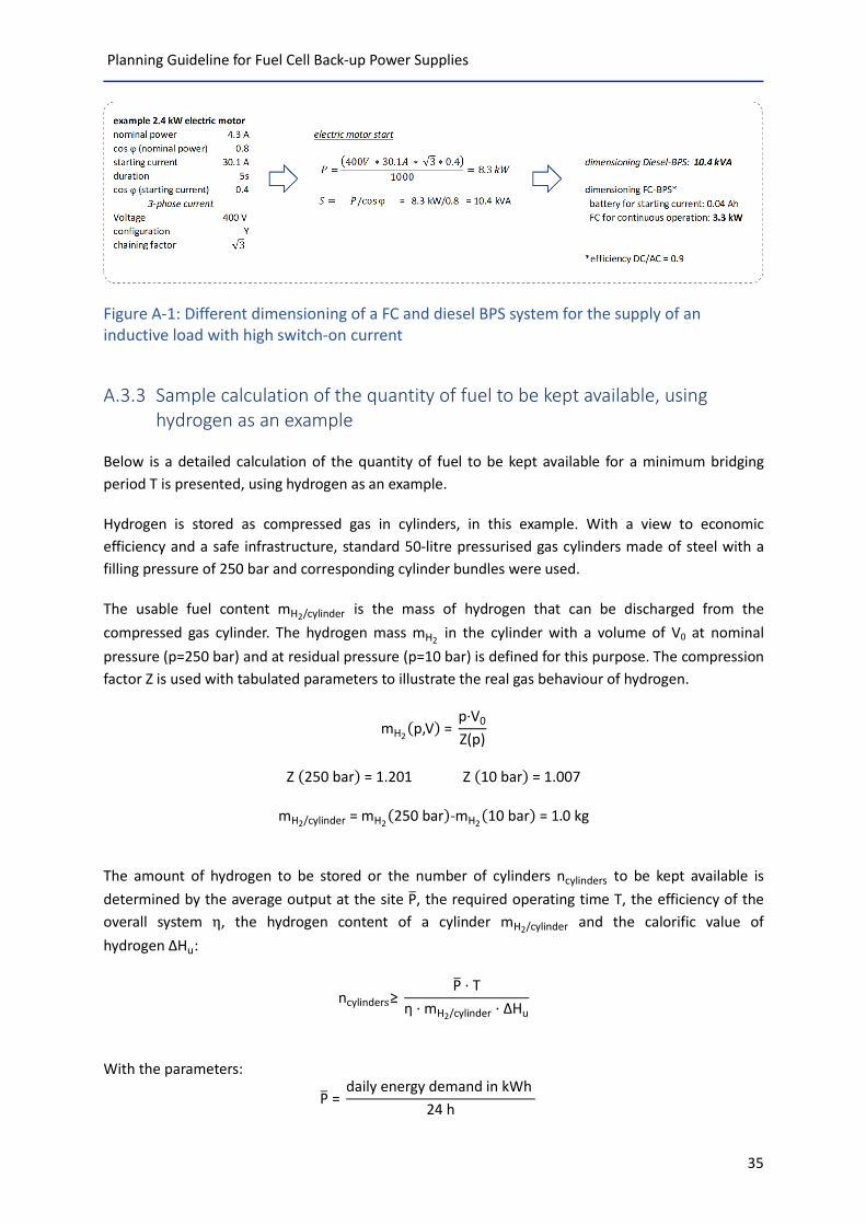
In the following example, the dimensioning of a diesel and a FC back-up power supply system for a
2.4 kW electric motor as a three-phase consumer in a Y-configuration is presented and compared.
Here, the starting current is 7 times the rated current.
P
Q S
ϕ
Planning Guideline for Fuel Cell Back-up Power Supplies
35
Figure A-1: Different dimensioning of a FC and diesel BPS system for the supply of an inductive load with high switch-on current
A.3.3 Sample calculation of the quantity of fuel to be kept available, using hydrogen as an example
Below is a detailed calculation of the quantity of fuel to be kept available for a minimum bridging
period T is presented, using hydrogen as an example.
Hydrogen is stored as compressed gas in cylinders, in this example. With a view to economic
efficiency and a safe infrastructure, standard 50-litre pressurised gas cylinders made of steel with a
filling pressure of 250 bar and corresponding cylinder bundles were used.
The usable fuel content mH2/cylinder is the mass of hydrogen that can be discharged from the
compressed gas cylinder. The hydrogen mass mH2 in the cylinder with a volume of V0 at nominal
pressure (p=250 bar) and at residual pressure (p=10 bar) is defined for this purpose. The compression
factor Z is used with tabulated parameters to illustrate the real gas behaviour of hydrogen.
mH2(p,V) =
p·V0
Z(p)
Z (250 bar) = 1.201 Z (10 bar) = 1.007
mH2/cylinder = mH2
(250 bar)-mH2(10 bar) = 1.0 kg
The amount of hydrogen to be stored or the number of cylinders ncylinders to be kept available is
determined by the average output at the site P�, the required operating time T, the efficiency of the
overall system η, the hydrogen content of a cylinder mH2/cylinder and the calorific value of
hydrogen ΔHu:
ncylinders≥ P� · T
η · mH2/cylinder · ΔHu
With the parameters:
P� = daily energy demand in kWh
24 h

Planning Guideline for Fuel Cell Back-up Power Supplies
36
T = Truntime+Ttest operation
ηSys = system efficiency
mH2/cylinder = mass of hydrogen per cylinder
ΔHu = 33.33 kWh/kg
A.3.4 Supply of fuel The supply of fuel determines the possible bridging period and allows the economic potential to be
maximised through intelligent design.
There are often options for renting or buying the storage media. The most cost-effective alternative
can be selected depending on the application. The operator is responsible for the maintenance of the
storage units when they are purchased.
In the case of gaseous fuels, it is also important to minimise the number of soluble compounds.
Cylinders must be checked for leaks every time they are exchanged. This means for hydrogen, for
example, that the supply of pre-assembled cylinder bundles is to be favoured. A cylinder bundle
consists, for example, of 12 individual cylinders which are permanently installed in a frame. The
logistics concept and the possibilities of delivery (weight restrictions) may contradict such a solution.
Note:
Installed exchangeable cylinders may be used even if the inspection period has
already been exceeded (no exchange of full cylinders). The maximum period for
steel cylinders is twice the maximum permitted period (i.e. max. 20 years), and 1.5
times for compound containers (i.e. max. 15 years).
A.3.5 Supply concept for locations with restricted accessibility Locations that are easily accessible by road can be served directly by truck. Yet in the case of locations
with limited accessibility, a transfer point will need to be defined at which the standard road ends and
the required cylinders can be transferred from the regular truck to an off-road delivery vehicle.
Depending on the terrain, this might be an off-road vehicle that has been modified with appropriate
ventilation systems, anchoring facilities and a gas-tight partition wall in order to transport permit-free
quantities of gas cylinders directly to the location – or to the next transfer point, if required. For
locations with very limited access, it may be necessary to transport the gas over the “last mile” using
appropriate alternative equipment (such as sturdy pushcarts or some other type of gas cylinder
transportation cart).
Figure A-2 illustrates various example transport concepts according to the accessibility of the delivery
location.

Planning Guideline for Fuel Cell Back-up Power Supplies
37
When selecting gas suppliers, attention must therefore not only be given to the costs and purity of
the gas but should also focus on the options for delivery.
Figure A-2: Example of a supply concept depending on the location’s accessibility

Planning Guideline for Fuel Cell Back-up Power Supplies
38
A.4 List of figures Figure 2-1: Distinction between BPS systems in grid connected and off-grid systems Figure 2-2: Overview of the planning guideline structure Figure 3-1: Schematic diagram of a fuel cell system Figure 3-2: Schematic diagram of a FC back-power supply system Figure 3-3: Typical characteristics of commercially available fuel cell systems Figure 3-4: Fuel cells are particularly suitable for long bridging times Figure 3-5: Gravimetric energy densities of various fuels Figure 3-6: Example of a hydrogen-powered FC UPS Figure 3-7: Example of a methanol-powered FC back-up power supply system Figure 4-1: Selecting the fuel cell and the corresponding fuel Figure 4-2: Schematic representation of a load curve and the resulting dimensioning of FC and diesel back-up power supply systems. Figure 4-3: Varying modular concepts Figure 4-4: Example of a circuit configuration for supplying AC and DC loads Figure 4-5: Example of a circuit configuration to supply purely DC consumers Figure A-1: Different dimensioning of a FC and diesel BPS system for the supply of an inductive load with high switch-on current Figure A-2: Example of a supply concept depending on the location’s accessibility

Planning Guideline for Fuel Cell Back-up Power Supplies
39
A.5 Authors
Benedikt Eska (Technology Management SK):
2009 founding of Technology Management SK – a consulting firm with focus on fuel cell tech-
nology
First fuel cell project in 1999
2014 - 2017 Interim Managing Director of a start-up in the “Power from Heat” area
2011 - 2014 Lectureship for Energy Technologies at the Munich University of Applied Sciences
9 years in a leading position of a German fuel cell company and board member of the English
holding company.
More than 10 years of experience as a management consultant
Degree in Physics, TU Munich
Several projects in the field of UPS systems for critical infrastructure including site surveying
and preparation of technical specifications for tender documents
Marcel Corneille (EMCEL GmbH):
Founded EMCEL GmbH in 2012, Managing Director
Founding of EMCEL engineering office in 2009
10 years professional experience at
o DaimlerChrysler AG
o Ballard Power Systems AG
o XCELLSIS GmbH
Degree in Mechanical Engineering
Several projects in the field of planning of FC UPS systems and hydrogen refuelling stations,
as well as their standard-compliant development

Clean Power Net (CPN) is funded by the Federal Ministry of Transport and Digital Infrastructure and coordinated by the National Organisation Hydrogen and Fuel Cell Technology (NOW GmbH).
www.cleanpowernet.de