PLANNING - Federal Signal Corporation · PDF file2-2. SIGNALING FORMAT SPECIFICATIONS ... 4-6....
24
i SAFETY NOTICES People’s lives depend on your selection of suitable equipment and installation sites and your safe installation, service, and operation of our products. Federal Signal recommends the following publications from the Federal Emergency Management Agency for assistance with planning an outdoor warning system: 1. The “Outdoor Warning Guide (CPG 1-17), 2. “Civil Preparedness, Principles of Warning” (CPG 1- 14), 3. FEMA-REP-1, Appendix 3 (Nuclear Plant Guideline), and 4. FEMA-REP-10 (Nuclear Plant Guideline). Contact Federal Warning System’s Customer Care Center at: http://www.federalwarningsystems.com or 1-800-524-3021 for further information about these publications. It is important to read, understand and follow all instructions shipped with this product. In addition, listed below are some other important safety instructions and precautions you should follow. PLANNING • If suitable warning equipment is not selected, the installation site for the siren is not selected properly or the siren is not installed properly, it may not produce the intended optimum audible warning. Follow Federal Emergency Management Agency (FEMA) recommendations. • If sirens are not activated in a timely manner when an emergency condition exists, they cannot provide the intended audible warning. It is imperative that knowledgeable people, who are provided with the necessary information, are available at all times to authorize the activation of the sirens. • When sirens are used out of doors, people indoors may not be able to hear the warning signals. Separate warning devices or procedures may be needed to effectively warn people indoors. • The sound output of sirens is capable of causing permanent hearing damage. To prevent excessive exposure, carefully plan siren placement, post warnings, and restrict access to areas near sirens. • Activating the sirens may not result in people taking the desired actions if those to be warned are not properly trained about the meaning of siren sounds. Siren users should follow FEMA recommendations and instruct those to be warned of correct actions to be taken. • A siren that does not work will not provide any warning. After installation, service, or maintenance, test the siren system to confirm that it is operating properly. Test the system regularly to confirm that it will be operational in an emergency. • If future service and operating personnel do not have these instructions to refer to, the siren system may not provide the intended audible warning and service personnel may be exposed to permanent hearing loss, bodily injury, or death. File these instructions in a safe place and refer to them periodically. Give a copy of these instructions to new recruits and trainees. Also give a copy to anyone who is going to service or repair the siren.
Transcript of PLANNING - Federal Signal Corporation · PDF file2-2. SIGNALING FORMAT SPECIFICATIONS ... 4-6....
i
SAFETY NOTICES People’s lives depend on your selection of suitable equipment and installation sites and your safe installation, service, and operation of our products. Federal Signal recommends the following publications from the Federal Emergency Management Agency for assistance with planning an outdoor warning system: 1. The “Outdoor Warning Guide (CPG 1-17), 2. “Civil Preparedness, Principles of Warning” (CPG 1-14), 3. FEMA-REP-1, Appendix 3 (Nuclear Plant Guideline), and 4. FEMA-REP-10 (Nuclear Plant Guideline). Contact Federal Warning System’s Customer Care Center at: http://www.federalwarningsystems.com or 1-800-524-3021 for further information about these publications. It is important to read, understand and follow all instructions shipped with this product. In addition, listed below are some other important safety instructions and precautions you should follow.
PLANNING
• If suitable warning equipment is not selected, the installation site for the siren is not selected properly or the siren is not installed properly, it may not produce the intended optimum audible warning. Follow Federal Emergency Management Agency (FEMA) recommendations.
• If sirens are not activated in a timely manner when an emergency condition exists,
they cannot provide the intended audible warning. It is imperative that knowledgeable people, who are provided with the necessary information, are available at all times to authorize the activation of the sirens.
• When sirens are used out of doors, people indoors may not be able to hear the
warning signals. Separate warning devices or procedures may be needed to effectively warn people indoors.
• The sound output of sirens is capable of causing permanent hearing damage. To
prevent excessive exposure, carefully plan siren placement, post warnings, and restrict access to areas near sirens.
• Activating the sirens may not result in people taking the desired actions if those to
be warned are not properly trained about the meaning of siren sounds. Siren users should follow FEMA recommendations and instruct those to be warned of correct actions to be taken.
• A siren that does not work will not provide any warning. After installation,
service, or maintenance, test the siren system to confirm that it is operating properly. Test the system regularly to confirm that it will be operational in an emergency.
• If future service and operating personnel do not have these instructions to refer to,
the siren system may not provide the intended audible warning and service personnel may be exposed to permanent hearing loss, bodily injury, or death. File these instructions in a safe place and refer to them periodically. Give a copy of these instructions to new recruits and trainees. Also give a copy to anyone who is going to service or repair the siren.

ii
SAFETY NOTICES
People’s lives depend on your safe installation, service and operation of our products. It is important to read, understand and follow all instructions shipped with this product. In addition, listed below are some other important safety instructions and precautions you should follow:
INSTALLATION & SERVICE • Electrocution or severe personal injury can occur when performing various
installation and service functions such as making electrical connections, drilling holes, or lifting equipment. Therefore experienced electricians in accordance with national, state and any other electrical codes having jurisdiction should perform installation. All work should be performed under the direction of the installation or service crew safety foreman.
• The sound output of sirens is capable of causing permanent hearing damage. To
prevent excessive exposure, carefully plan siren placement, post warnings and restrict access to areas near the sirens. Sirens may be operated from remote control points. Whenever possible, disconnect all siren power including batteries before working near the siren.
• After installation or service, test the siren system to confirm that it is operating
properly. Test the system regularly to confirm that it will be operational in an emergency.
• If future service personnel do not have these warnings and all other instructions
shipped with the equipment to refer to, the siren system may not provide the intended audible warning and service personnel may be exposed to death, permanent hearing loss, or other bodily injury. File these instructions in a safe place and refer to them periodically. Give a copy of these instructions to new recruits and trainees. Also, give a copy to anyone who is going to service or repair the sirens. For additional copies, call the Federal Warning Systems Customer Care Center at 800-524-3021 or write to them at 2645 Federal Signal Drive, University Park, IL 60466.
OPERATION
Failure to understand the capabilities and limitations of your siren system could result in permanent hearing loss, other serious injuries or death to persons too close to the sirens when you activate them or to those you need to warn. Carefully read and thoroughly understand all safety notices in this manual and all operations-related-items in all instruction manuals shipped with equipment. Thoroughly discuss all contingency plans with those responsible for warning people in your community, company, or jurisdiction.

iii
WARNING Read and understand the information contained in this manual, before attempting to install or service this siren.
Pay careful attention to the following notices located on the equipment. NOTICES – INTERNALLY PLACED

iv
Limited Warranty The Signal Division, Federal Signal Corporation, warrants each new product to be free from defects in material and workmanship, under normal use and service, for a period of two years on parts replacement and bench labor (one year for Informer, EAS, and Federal software products) from the date of delivery to the first user-purchaser. Federal Warning Systems warrants every 2001 Siren (Top of pole only) to be free from defects in material, per our standard warranty, under normal use and service for a period of five years on parts replacement. During this warranty period, the obligation of Federal is limited to repairing or replacing, as Federal may elect, any part or parts of such product which after examination by Federal discloses to be defective in material and/or workmanship. Federal will provide warranty for any unit which is delivered, transported prepaid, to the Federal factory or designated authorized warranty service center for examination and such examination reveals a defect in material and/or workmanship. This warranty does not cover travel expenses, the cost of specialized equipment for gaining access to the product, or labor changes for removal and re-installation of the product. The Federal Signal Corporation warranty shall not apply to components or accessories that have a separate warranty by the original manufacturer, such as, but not limited to, batteries. This warranty does not extend to any unit which has been subjected to abuse, misuse, improper installation or which has been inadequately maintained, nor to units which have problems related to service or modification at any facility other than Federal factory or authorized warranty service centers. Moreover, Federal shall have no liability with respect to defects arising in Products through any cause other than ordinary use (such as, for example, accident, fire, lightning, water damage, or other remaining acts of god). THERE ARE NO OTHER WARRANTIES, EXPRESSED OR IMPLIED, INCLUDING BUT NOT LIMITED TO, ANY IMPLIED WARRANTIES OF MERCHANTABILITY OR FITNESS FOR A PARTICULAR PURPOSE. IN NO EVENT SHALL FEDERAL BE LIABLE FOR ANY LOSS OF PROFITS OR ANY INDIRECT OR CONSEQUENTIAL DAMAGES ARISING OUT OF ANY SUCH DEFECT IN MATERIAL WORKMANSHIP.
2645 Federal Signal Drive, University Park, IL 60466 Phone: (800) 524-3021 Fax: (708) 534-4865
Website: http://www.federalwarningsystems.com
iv
TABLE OF CONTENTS Paragraph Page
SECTION I - CHARACTERISTICS 1-1. GENERAL ........................................................................................................................... 1-1
SECTION II - SPECIFICATIONS 2-1. CONTROLLER SPECIFICATIONS ................................................................................... 2-1 2-2. SIGNALING FORMAT SPECIFICATIONS ...................................................................... 2-1 2-3. OPTIONAL RF RECEIVER SPECIFICATIONS ............................................................... 2-2
SECTION III - INSTALLATION
3-1. SIREN CONTROLLER INSTALLATION ......................................................................... 3-1 3-2. FACTORS AFFECTING RADIO RECEPTION AND ANTENNA CONNECTION ........ 3-7 3-3. PRE-OPERATION CHECKOUT ........................................................................................ 3-7
SECTION IV – RF RECEIVER DESCRIPTION, ALIGNMENT AND TESTING
4-1. RECEIVER MODULE GENERAL DESCRIPTION .......................................................... 4-1 4-2. FEATURES.......................................................................................................................... 4-1 4-3. TERMINAL STRIPS & JACKS, CONTROLS ................................................................... 4-1 4-4. THEORY OF OPERATION ................................................................................................ 4-2 4-5. TEST AND ALIGNMENT .................................................................................................. 4-3 4-6. TCS/DCS PROGRAMMING............................................................................................... 4-4
SECTION V - MAINTENANCE AND SPARE PARTS
5-1. PREVENTIVE MAINTENANCE ....................................................................................... 5-1 5-2. INSPECTION....................................................................................................................... 5-1 5-3. POWER SUPPLY TESTING............................................................................................... 5-1 5-4. SERVICE ............................................................................................................................. 5-1 5-5. SPARE PARTS LIST........................................................................................................... 5-1
LIST OF ILLUSTRATIONS Figure Page 3-1. Typical Installation ............................................................................................................... 3-1 3-2. Contactor Wiring .................................................................................................................. 3-2 4-1. PL Programming Chart ........................................................................................................ 4-5 5-1. FC Assembly Drawing .......................................................................................................... 5-2
SECTION I CHARACTERISTICS
1-1. GENERAL. The FC series siren control units provide RF and/or wire line control of individually programmable timing cycles for contact closure outputs. The versatility of the FC makes it an ideal choice for virtually all siren control applications or any other process that can be controlled via relay contacts. A. Features
The microprocessor based controller contains the following features:
Synthesized Radio Receiver (Low Band, High Band, or UHF - 3 separate models)
Two-Tone and DTMF Decoders
Up to 4 Individually Programmable Output Relays
Siren Tone Generator
Push Buttons for Local Control
Contact Closure Inputs for Land Line Control
RS232 Programming Port
Diagnostic LEDs
Single PCB Reliability
B. Programmability
All functions of the FC controller are programmable from a XP compatible computer with an RS232 port using Federal Signal's easy to use FSPWARE programming software. The software allows easy configuration, uploading and downloading of control programs. Programming options include:
Radio Receiver Frequency Single and Two-Tone Sequential Decode Tones
& Tone Lengths DTMF Decode Digits Output Relay Timing Patterns Tone Generation Frequencies & Durations
Up to six (6) control timing sequences may be programmed into the controller. Standard siren control timings can be chosen or custom relay output timings can be designed. The control functions can be activated from any combination of six (6) Single Tone, Two Tone Sequential and/or DTMF tones. Timing sequences can also be initiated using the local push buttons and contact closure inputs. Configuration programs are stored in nonvolatile E2 memory to ensure retention even during a complete power failure.
1-1

SECTION II
SPECIFICATIONS 2-1. CONTROLLER SPECIFICATIONS Electrical AC Power Inputs .............. .............120 or 208 - 240 VAC +/- 10%, 50-60 Hz 12VDC Battery Input........ .............11 - 15 VDC @ JP5-2 48VDC Battery Input........ .............14 - 60 VDC @ JP5-4 Input Current
@120 VAC......... ............180 mA AC (maximum)
Input Current @12 VDC ......................460 mA DC (maximum)
Relay Outputs .... ..................... .......SPST (2 relays standard, 4 relays maximum) 5 A @ 30 VDC 5 A @ 240 VAC Relay Output Timings .......... ..........0.5 seconds to 999 seconds 2-2. SIGNALING FORMAT SPECIFICATIONS 6 user programmable functions are available in addition to the 5 preset functions: ARM, DISARM, REPORT, GROWL TEST, and MASTER RESET. Wildcard options can be used for each of the DTMF strings. Two-Tone Sequential Frequency range 282 Hz - 3000 Hz Tone timing 0.5 sec - 0.25 sec minimum to 8 sec max. Intertone Gap 400 ms (maximum) Tone Accuracy +/- 1.5% Tone Spacing 5.0% Single Tone Frequency range 282 Hz - 3000 Hz Tone timing 0.5 sec. - 8 sec maximum Tone Accuracy +/- 1.5% Minimum Tone Spacing 5.0% DTMF (All timings in milliseconds) String length 3 - 12 standard DTMF characters Mark/Space timing: Decoder Minimum 40ms/40ms (below 40/40 consult factory) Decoder Maximum 800ms total mark/space timing per function
Encoder 100ms/100ms mark/space timing Space between Stacked codes, minimum 1.5 seconds FSK Baud rate 1200 bps Modem type MSK (minimal shift key) Mark frequency 1200 Hz Space frequency 1800 Hz Error checking 16 bit CRC Relay Outputs 4 relay outputs SPST (2 relays standard, 4 relays max.) Contact Rating 5 A @ 28 VDC 5 A @ 240 VAC
2-1

Audio Output (Optional) Output Voltage >2 V peak to peak Maximum Load 8 Ohms Total Harmonic Distortion < 10% @ 1 kHz Sinewave Serial Communications Serial Port Configuration RS232C 1200,N,8,1, DCE Environmental Operating Temperature -30 to +60° C Dimensions (H x W x D) Height 13.50 ” Width 9.84 ” Depth 6.00 ” 2-3. OPTIONAL RF RECEIVER SPECIFICATIONS Antenna Impedance 50 ohms, +/- 10 ohms Frequency range 30 - 50 MHz, 150 - 172 MHz, 450 - 470 MHz Frequency Spread +/- 4.9 MHz for 30 - 50 MHz, +/- 1.5 MHz for 150 - 174 MHz, +/- 8.0 MHz for 450 - 470 MHz Freq stability over temp range =/< 2.5ppm from -30°C to +60°C Spurious Response & Image Rejection LB =/> -70 dBm
HB =/> -70 dBm UHF =/> -70 dBm
(measured per EIA-603, part 4.1.8) Intermodulation Distortion Rejection LB =/> -70 dBm
HB =/> -70 dBm UHF =/> -70 dBm
(measured per EIA-603, part 4.1.9) Adjacent Channel Selectivity LB =/> -70 dBm
HB =/> -70 dBm UHF =/> -70 dBm
(measured per EIA-603, part 4.1.6) Sensitivity - 12dB SINAD =/< 0.35 uV for 12 dB SINAD per EIA-603, Part 4.1.4 Sensitivity - 20dB Quieting =/< 0.5 uV, 20 dB quieting Squelch Sensitivity Minimum squelch setting = Open Squelch w/ 1kHz tone @ 3kHz deviation Maximum squelch setting =< 29 dB SINAD Shall be set at the reference decode sensitivity
(20dB SINAD) Shall open and close in less than 250 ms per EIA-603, Part 4.1.13.2.4 2-2

Audio Output with 1KHz tone at 3KHz deviation 0.8 Vp-p +/- 0.20 Vp-p Audio frequency response 300 Hz – 3000 Hz, +/- 1 dB, w/ 6 dB per octave de-emphasis Hum and Noise -35 dB relative to full quieting signal w/1 kHz tone @ 3 kHz
deviation Audio distortion with 1Kc tone at 3Kc deviation < 10% Operating current < 80 mA Operating Voltage 8 Volts DC +/- 0.25 Volts Operating temp range -30° + 60°C Humidity range 0 - 98%, non-condensing Size 3.5” x 3.5” Weight < 5 ounces
This device complies with Part 15 of the FCC Rules. Operation is subject to the following two conditions: (1) This device may not cause harmful interference, and (2) this device must accept any interference received, including interference that may cause undesired operation.
CAUTION
Changes or modifications not expressly approved by Federal Signal
could void the user’s authority to operate the equipment. NOTE: This equipment has been tested and found to comply with the limits for a Class B digital device, pursuant to part 15 of the FCC Rules. These limits are designed to provide reasonable protection against harmful interference in a residential installation. This equipment generates, uses and can radiate radio frequency energy and, if not installed and used in accordance with the instructions, may cause harmful interference to radio communications. However, there is no guarantee that interference will not occur in a particular installation. If this equipment does cause harmful interference to radio or television reception, which can be determined by turning the equipment off and on, the user is encouraged to try to correct the interference by one or more of the following measures: - Reorient or relocate the receiving antenna. - Increase the separation between the equipment and receiver. - Connect the equipment into an outlet on a circuit different from that to which the receiver is connected. - Consult the dealer or an experienced radio/TV technician for help.
2-3
SECTION III INSTALLATION
3-1. SIREN CONTROLLER INSTALLATION The information in this section provides guidelines to aid the user. The FC series controllers are factory installed in 2001DC siren control cabinets. Therefore, parts A – C of this section are not applicable to 2001DC controllers.
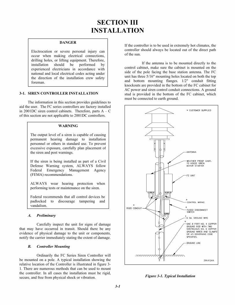
A. Preliminary Carefully inspect the unit for signs of damage that may have occurred in transit. Should there be any evidence of physical damage to the unit or components, notify the carrier immediately stating the extent of damage. B. Controller Mounting Ordinarily the FC Series Siren Controller will be mounted on a pole. A typical installation showing the relative location of the Controller is illustrated in figure 3-1. There are numerous methods that can be used to mount the controller. In all cases the installation must be rigid, secure, and free from physical shock or vibration.
If the controller is to be used in extremely hot climates, the controller should always be located out of the direct path of the sun. If the antenna is to be mounted directly to the control cabinet, make sure the cabinet is mounted on the side of the pole facing the base station antenna. The FC unit has three 5/16" mounting holes located on both the top and bottom mounting flanges. 1/2" conduit fitting knockouts are provided in the bottom of the FC cabinet for AC power and siren control conduit connections. A ground stud is provided in the bottom of the FC cabinet, which must be connected to earth ground.
Figure 3-1. Typical Installation
3-1
DANGER Electrocution or severe personal injury canoccur when making electrical connections,drilling holes, or lifting equipment. Therefore,installation should be performed byexperienced electricians in accordance withnational and local electrical codes acting underthe direction of the installation crew safetyforeman.
WARNING The output level of a siren is capable of causingpermanent hearing damage to installationpersonnel or others in standard use. To preventexcessive exposure, carefully plan placement ofthe siren and post warnings.
If the siren is being installed as part of a CivilDefense Warning system, ALWAYS followFederal Emergency Management Agency(FEMA) recommendations. ALWAYS wear hearing protection when performing tests or maintenance on the siren. Federal recommends that all control devices be padlocked to discourage tampering and vandalism.

C. Electrical Connections
1. Install two ½” user supplied conduit fittings
bottom of the FC cabinet.
2. Route ½” conduit (steel preferred) between a user supplied fused disconnect switch, and the conduit fittings in the bottom of the FC cabinet. Fuse the disconnect switch with a 1 Amp fast acting fuse.
3. Follow the instructions included with the
lightning protector (supplied with controller) and install in the AC service disconnect.
4. Set the AC input voltage selector switch located near the bottom right of the controller for either 110 or 220 VAC input voltage. Push the switch up for 110 VAC or down for 220 VAC. Route two 12AWG wires between the fused disconnect and the AC input at JP19(see Figure 3-2). 5. Route a 6AWG ground wire from the earth grounding rod to the FC cabinet ground stud. 6. Route ½” conduit between the conduit fittings on the bottom of the FC control cabinet and the siren motor starter cabinet. 7. Route two 12AWG wires between JP18 on the FC circuit board and the siren motor contactor as follows. Connect one wire between JP18-8 of the FC control and 3 of the contactor. Connect one wire between JP18-7 and L1 of the contactor (see figure 3-2). Make other connections to the relay outputs at JP18 as necessary. 8. If the siren is to be controlled remotely via a momentary contact closure, apply the contact closure to the appropriate input on JP12 (see Figure 5-1 for pin-outs of connectors). The wire run from the contact to JP12 must not exceed 50’. A model TRC1020 can be purchased for each function if longer wire runs are required. The inputs on JP12 require 1-second contact closures.
Figure 3-2. Contactor Wiring
3-2
WARNING
Install the siren electrical system in compliance withlocal electrical codes and NEC recommendations. Federal Signal also recommends that all user-installed conduit connections enter from bottom of cabinet.
CAUTION SIREN UNITS AND CONTROL UNITS MUST BE SOLIDLY CONNECTED TO AN EARTH GROUND. If the siren is installed on a building, ground the system to a metallic object known to be grounded. For pole mounted installations, drive a metal rod or bar at least eight feet into the ground, as close as practical to the base of the pole. FOR MAXIMUM PROTECTION, USE A SEPARATE, CONTINUOUS 6AWG OR LARGER WIRE FROM THE SIREN FRAME TO GROUND AND FROM THE CABINET OF EACH SIREN UNIT TO GROUND.
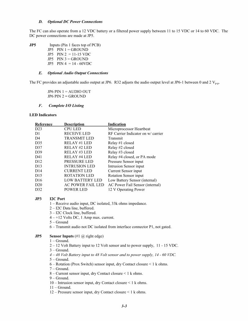
D. Optional DC Power Connections
The FC can also operate from a 12 VDC battery or a filtered power supply between 11 to 15 VDC or 14 to 60 VDC. The DC power connections are made at JP5.
JP5 Inputs (Pin 1 faces top of PCB)
JP5 PIN 1 = GROUND JP5 PIN 2 = 11-15 VDC JP5 PIN 3 = GROUND JP5 PIN 4 = 14 - 60VDC E. Optional Audio Output Connections The FC provides an adjustable audio output at JP6. R32 adjusts the audio output level at JP6-1 between 0 and 2 Vp-p. JP6 PIN 1 = AUDIO OUT JP6 PIN 2 = GROUND F. Complete I/O Listing LED Indicators
Reference Description Indication D23 CPU LED Microprocessor Heartbeat D1 RECEIVE LED RF Carrier Indicator on w/ carrier D4 TRANSMIT LED Transmit D35 RELAY #1 LED Relay #1 closed D37 RELAY #2 LED Relay #2 closed D39 RELAY #3 LED Relay #3 closed D41 RELAY #4 LED Relay #4 closed, or PA mode D12 PRESSURE LED Pressure Sensor input D13 INTRUSION LED Intrusion Sensor input D14 CURRENT LED Current Sensor input D15 ROTATION LED Rotation Sensor input D16 LOW BATTERY LED Low Battery Sensor (internal) D20 AC POWER FAIL LED AC Power Fail Sensor (internal) D32 POWER LED 12 V Operating Power
JP3 I2C Port
1 – Receive audio input, DC isolated, 33k ohms impedance. 2 – I2C Data line, buffered. 3 – I2C Clock line, buffered. 4 – +12 Volts DC, 1 Amp max. current. 5 – Ground 6 – Transmit audio not DC isolated from interface connector P1, not gated.
JP5 Sensor Inputs (#1 @ right edge) 1 – Ground.
2 – 12 Volt Battery input to 12 Volt sensor and to power supply, 11 - 15 VDC. 3 – Ground.
4 – 48 Volt Battery input to 48 Volt sensor and to power supply, 14 - 60 VDC. 5 – Ground.
6 – Rotation (Prox Switch) sensor input, dry Contact closure < 1 k ohms. 7 – Ground. 8 – Current sensor input, dry Contact closure < 1 k ohms. 9 – Ground. 10 – Intrusion sensor input, dry Contact closure < 1 k ohms. 11 – Ground. 12 – Pressure sensor input, dry Contact closure < 1 k ohms.
3-3

JP6 Test Speaker 1 – 0 to 2 V p-p, Audio Source: Receiver Audio during P.A. functions,
Siren Audio during Electronic Siren functions. 2 – Ground. JP7 Serial and FLASH programming Port
1 – RXD Disable, grounded during programming to disable RXD from onboard Digital Modem IC. 2 – TXD, standard RS232 levels. 3 – RXD, standard RS232 levels. 4 – Ground.
5 – Processor Reset not, pulsed low (to Ground) during FLASH programming.
JP8 Short To Set Deviation 1 – Short to Ground (JP8, pin 2), causes unit to transmit for setting deviation. 2 – Ground. JP9 Receiver Module 1 – Ground. 2 – +8 Volts DC, < 100 mA current. 3 – Synthesizer programming Clock line, 0 to 5 Volt levels. 4 – Synthesizer programming Data line, 0 to 5 Volt levels. 5 – Synthesizer programming Latch line, 0 to 5 Volt levels. 6 – Carrier Detect, goes low with carrier, 0 to 5 Volt levels. 7 – Receive Audio, De-emphasized, 700 to 900 mVp-p w/1 kHz tone
@ 3 kHz dev. 8 – No connection. JP11 LEDs on w/ Intrusion 1 – Short to pin 2, to disable LEDs when Intrusion switch is closed. JP12 Remote Activation and Sensor Inputs (#1 @ right edge of connector) 1 – Ground.
2 – Remote Activation Input #1, Activates Functions under code 1, dry Contact closure < 1 k ohms.
3 – Ground. 4 – Remote Activation Input #2, Activates Functions under code 2,
dry Contact closure < 1 k ohms. 5 – Ground.
6 – Remote Activation Input #3, Activates Functions under code 3, dry Contact closure < 1 k ohms.
7 – Ground. 8 – Remote Activation Input #4, Activates Functions under code 4,
dry Contact closure < 1 k ohms. 9 – Ground. 10 – Rotation Sensor Input (Current Sensor), dry Contact closure < 1 k ohms. 11 – Ground. 12 – Remote AC Sensor Input, dry Contact closure < 1 k ohms.
JP13 CTCSS Encoder / Decoder 1 – Receive audio, not DC isolated, set to 1 V p-p w/ 1 kHz tone @ 3 kHz dev. 2 – Ground. 3 – +8 Volts DC, < 100 mA current.
4 – Decode not & PTT line, low with decode, set low by processor during transmit.
5 – Transmit audio, 0 to 2 V p-p of Digital data or Tone.
3-4

JP14 Short to Test Relay Output #1 1 – Short to pin 2, to engage Relay output #1.
JP15 Short to Test Relay Output #2 1 – Short to pin 2, to engage Relay output #2.
JP16 Short to Test Relay Output #3 1 – Short to pin 2, to engage Relay output #3.
JP17 Short to Test Relay Output #4 1 – Short to pin 2, to engage Relay output #4. JP18 Relay Outputs, 3 Amps, up to 240 VAC, (#1 @ right edge of connector) 1 – Relay 4, N.O. or N.C., depending on jumper JU2 2 – Relay 4, Common 3 – Relay 3, N.O. or N.C., depending on jumper JU1 4 – Relay 3, Common 5 – Relay 2, N.O. 6 – Relay 2, Common 7 – Relay 1, N.O. 8 – Relay 1, Common JP19 AC Power Input 1 & 2 - 120 or 240 VAC +/- 10%, 60 Hz JP20 Spare 1 – Directly to processor pin #54 (ADC7). 2 – Ground. P1 Transceiver Interface 1 – Transmit audio, DC isolated, 0 to 1 Vp-p 2 – Receive audio, DC isolated, 350 mVp-p to 3 Vp-p 3 – PTT not, goes low during transmit 4 – Ground 5 – +12 Volts DC, 1 Amp max. current. 6 – Carrier Detect not, set low during receive 7 – No connection 8 – Ground 9 – Ground TP1 RX Data Receive data from digital modem IC, 0 to 5 Volts. TP2 Receive audio - Incoming receive audio, connected to P1 pin 2 TP3 Receive audio level set - Receive audio set to 1 Vp-p using R58 TP4 Receive audio to Two-Tone Decoder Audio at last stage before two-tone comparator, 1 to 3 Vp-p. TP5 Receive audio from Two-Tone Decoder to processor Audio after two-tone comparator, square waves to processor, 0 to 5 Vp-p.
TP6 DTMF Decoder STD - Goes low whenever a DTMF digit is being decoded. TP7 Two-Tone Decoder, Low Pass Filter Enable Goes high when processor is decoding a tone < 500 Hz TP8 5 Volt Regulated power supply
3-5
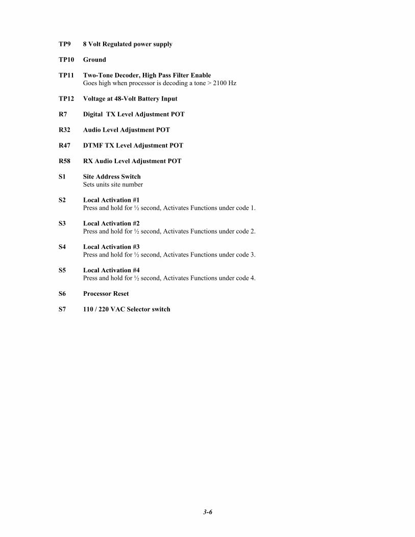
TP9 8 Volt Regulated power supply TP10 Ground TP11 Two-Tone Decoder, High Pass Filter Enable Goes high when processor is decoding a tone > 2100 Hz TP12 Voltage at 48-Volt Battery Input R7 Digital TX Level Adjustment POT
R32 Audio Level Adjustment POT
R47 DTMF TX Level Adjustment POT
R58 RX Audio Level Adjustment POT S1 Site Address Switch Sets units site number S2 Local Activation #1
Press and hold for ½ second, Activates Functions under code 1. S3 Local Activation #2
Press and hold for ½ second, Activates Functions under code 2. S4 Local Activation #3
Press and hold for ½ second, Activates Functions under code 3. S5 Local Activation #4
Press and hold for ½ second, Activates Functions under code 4. S6 Processor Reset S7 110 / 220 VAC Selector switch
3-6
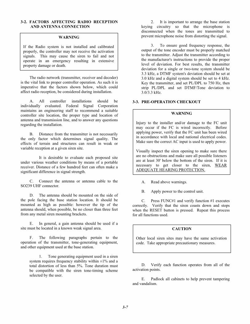
3-2. FACTORS AFFECTING RADIO RECEPTION AND ANTENNA CONNECTION
The radio network (transmitter, receiver and decoder) is the vital link to proper controller operation. As such it is imperative that the factors shown below, which could affect radio reception, be considered during installation. A. All controller installations should be individually evaluated. Federal Signal Corporation maintains an engineering staff to recommend a suitable controller site location, the proper type and location of antenna and transmission line, and to answer any questions regarding the installation. B. Distance from the transmitter is not necessarily the only factor which determines signal quality. The effects of terrain and structures can result in weak or variable reception at a given siren site. It is desirable to evaluate each proposed site under various weather conditions by means of a portable receiver. Distance of a few hundred feet can often make a significant difference in signal strength. C. Connect the antenna or antenna cable to the SO239 UHF connector. D. The antenna should be mounted on the side of the pole facing the base station location. It should be mounted as high as possible: however the tip of the antenna should, when possible, be no closer than three feet from any metal siren mounting brackets. E. In general, a gain antenna should be used if a site must be located in a known weak signal area. F. The following paragraphs pertain to the operation of the transmitter, tone-generating equipment, and other equipment used at the base station.
1. Tone generating equipment used in a siren system requires frequency stability within ±1% and a total distortion of less than 5%. Tone duration must be compatible with the siren tone-timing scheme selected by the user.
2. It is important to arrange the base station keying circuitry so that the microphone is disconnected when the tones are transmitted to prevent microphone noise from distorting the signal.
3. To ensure good frequency response, the output of the tone encoder must be properly matched to the transmitter. Adjust the transmitter according to the manufacturer's instructions to provide the proper level of deviation. For best results, the transmitter deviation for a single or two-tone system should be 3.3 kHz, a DTMF system's deviation should be set at 3.0 kHz and a digital system should be set to 4 kHz. Key the transmitter, and set PL/DPL to 750 Hz, then strip PL/DPL and set DTMF/Tone deviation to 3.0/3.3 kHz.
3-3. PRE-OPERATION CHECKOUT
A. Read above warnings. B. Apply power to the control unit. C. Press FUNC#1 and verify function #1 executes correctly. Verify that the siren coasts down and stops when the RESET button is pressed. Repeat this process for all functions used.
D. Verify each function operates from all of the activation points.
E. Padlock all cabinets to help prevent tampering and vandalism.
3-7
WARNING If the Radio system is not installed and calibrated properly, the controller may not receive the activation signals. This may cause the siren to fail and not operate in an emergency resulting in extensive property damage or death.
WARNING
Injury to the installer and/or damage to the FC unit may occur if the FC is wired incorrectly. Before applying power, verify that the FC unit has been wired in accordance with local and national electrical codes. Make sure the correct AC input is used to apply power. Visually inspect the siren opening to make sure there are no obstructions and make sure all possible listeners are at least 30' below the bottom of the siren. If it is necessary to get closer to the siren, WEAR ADEQUATE HEARING PROTECTION.
CAUTION Other local siren sites may have the same activation code. Take appropriate precautionary measures.
SECTION IV RF RECEIVER DESCRIPTION, ALIGNMENT AND TESTING
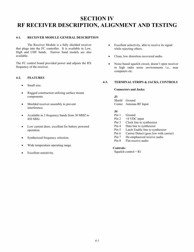
4-1. RECEIVER MODULE GENERAL DESCRIPTION
The Receiver Module is a fully shielded receiver that plugs into the FC controller. It is available in Low, High and UHF bands. Narrow band models are also available. The FC control board provided power and adjusts the RX frequency of the receiver. 4-2. FEATURES
• Small size. • Rugged construction utilizing surface mount
components. • Shielded receiver assembly to prevent
interference. • Available in 3 frequency bands from 30 MHZ to
450 MHz. • Low current draw, excellent for battery powered
operation. • Synthesized frequency selection. • Wide temperature operating range.
• Excellent sensitivity.
• Excellent selectivity, able to receive its signal
while rejecting others. • Clean, low distortion recovered audio. • Noise based squelch circuit, doesn’t open receiver
in high radio noise environments i.e., near computers etc.
4-3. TERMINAL STRIPS & JACKS, CONTROLS Connectors and Jacks:
J3 Shield Ground Center Antenna RF Input J4 Pin 1 Ground Pin 2 +8 VDC input Pin 3 Clock line to synthesizer Pin 4 Data line to synthesizer Pin 5 Latch Enable line to synthesizer Pin 6 Carrier Detect (goes low with carrier) Pin 7 De-emphasized receive audio Pin 8 Flat receive audio Controls: Squelch control = R1
4-1

4-4. THEORY OF OPERATION
A. The Power Supply
The receiver is designed to be powered from a regulated 8 volt (+/- .25v) DC supply. The incoming VDC passes to U5, a 5 volt regulator, which powers most of the receiver. The 8 volts also passes to U6, a 5 volt regulator which powers the synthesizer's VCO section.
B. The VCO/Synthesizer
U8 is a combination synthesizer / VCO. The frequency of this oscillator is determined by data programmed from the processor on pins 2, 3, and 4. The output from the oscillator drives U9, a double balanced mixer. U6, C32, C33, C34, R29, C29, C30 and C31 form filtered power supplies for the oscillator and digitals sections of the synthesizer.
U3 is a TCXO (temperature compensated crystal oscillator) at 20.95 MHZ which serves as a second LO for the receiver and as the reference for the synthesizer. When the synthesizer is locked to, or in lock with, the reference (U9), the voltage on TP2 will be about 3.7 Volts. When out of lock it will be 0 Volts.
C. The Receiver Section
The receive signal enters from the antenna, thru J1 and passes to FL1. FL1 is a bandpass filter that attenuates frequencies outside of the receive band. The signal is then passed on to U7. U7 serves as an RF amplifier which boosts the level of the signal by about 18dBm. The receive signal then passes thru bandpass filter FL2, which further attenuates out of band signals. These two filters keep out of band signals from entering the receiver and causing interference or de-sensitization. The filters also prevent the receiver from receiving the image frequency. The receiver can receive the VCO frequency + the IF frequency, or the VCO frequency - the IF frequency. The filters select the desired frequency and attenuate the other. The filters select the desired frequency and attenuate the other.
From FL2 the receive signal passes to U9, the first mixer. U9 mixes the receive signal with the VCO signal to produce the first IF (intermediate frequency) of 21.4 MHZ. The output of U9 is a double balanced output on pins 5 & 6. The 21.4 MHZ receive signal is fed from
pin 5, thru an impedance matching network, L6 and C46, to crystal filter Y3. Y3 filters out all frequencies except 21.4MHZ, +/= 7.5Kc. The signal is then fed to buffer amplifier Q1, which makes up some of the signal lost in Y3, and provides an impedance match to the receiver IC U4.
The 21.4 MHZ receive signal enters U4 on pin 1 where it passes to an internal mixer. Here it is mixed with 20.95 MHZ from U3, the reference oscillator. The resulting 450 KC signal comes out on pin 20 and is fed to ceramic filter Y1. I comes back in on pin 18, passes, through an amplifier and passes back out the ceramic filter Y2. Y1 and Y2 filter out all frequencies except 450 KC. The signal then passes in ,on pin 13, to an internal limiter / amplifier. A voltage reflecting the strength of the received signal appears on pin 4 and on TP1. This can be used to align the receiver. The 450 Kc receive signal then passes to an internal demodulator which, using L1, recovers the audio from the received signal. The audio appears at pin 8 of U4.
The receive audio is then fed to U2A, which
filters out frequencies above 3Kc then passes this audio to J2 pin 8. The receive audio also passes to U2B, which is a de-emphasis stage, filtering frequencies above 880 HZ by 6dB per octave. The output of U2B passes to J2 pin 7.
The receive audio from U4 pin 8 is also fed thru R15 to U1B, an opamp / filter. This amplifier filters out and boosts frequencies above 5Kc. This high frequency audio is converted to a DC voltage by D1, R13, R14 and C10. This voltage then passes to U1A, a comparator which, when the voltage drops below a threshold, will cause pin 1 to pull to ground. The squelch control sets the average DC level on pin 3 just above the threshold voltage. Thus when a signal is received by the receiver, the high frequency noise in the audio signal drops. The voltage produced by D1 drops, and the voltage on pin 3 drops below the threshold. The output on pin 1 pulls to ground, indicating the presence of a receive signal with sufficiently little noise. The output from pin 1 passes to J2 pin 6, the carrier detect output.
4-2

NOTICE
All receivers have been carefully tested and aligned at the factory prior to shipment and, under normal operating conditions and use, should not require attention beyond that normally given to electronic equipment. Replacement of a critical or major component may require subsequent realignment of the receiver. Receiver alignment should be performed only by persons experienced in this work using the proper test equipment.
The controller should be setup with a service monitor or other type of calibrated RF signal generator plugged directly into the antenna port. Program the FC with the desired RF frequency and relay output timings using the FSPWARE programming software.
4-5. TEST AND ALIGNMENT
Checking the power supplies; Power the unit up; Confirm +5 VDC +/- 0.25 V at the “+” end of C42. Confirm +5 VDC +/- 0.25V at the “+” end of C32. Checking for Synthesizer Lock;
Monitor voltage on TP2 with a high impedance DC volt meter;
The voltage on TP2 should from 3.0 to 3.9V. If not, the synthesizer is out of lock.
Setting the Synthesizer on frequency;
Using a service monitor set in receive mode, monitor the frequency of the VCO by placing a pickup loop on top of the synthesizer, U8.
The VCO frequency should be the receive frequency - 21.4mHz, unless the unit is a Lowband VHF unit, in which case the frequency will be 21.4 MHz + the receive frequency.
Adjust the frequency of the VCO using the trimmer cap in TCXO U3 until the frequency is within +/- 300Hz.
4-3
CAUTION
Remove power and use appropriate ESDprotection before removing or installing thereceiver on the control board to avoid damageto components.

Aligning the receiver;
Using a service monitor set in generate mode, inject an unmodulated RF carrier signal into the receiver.
Connect an Oscilloscope to TP1. Set the Oscilloscope for 20mV per Division, Bandwidth limiting On, and a DC offset of 0.60 to 1.0Volts, whatever is required to see the trace on the scope.
Turn up the signal level into the receiver until the voltage on TP1 begins to rise.
Adjust the coils in FL1 and then FL2 for the most voltage on TP1. TP1 will only rise to about 2 volts so it will be necessary to turn down the level from the service monitor during the tuning process.
Re-tune the coils in FL1 and FL2 after the first
pass through, as tuning the stages ahead of a coil can change it’s tuning.
Inject a 100uV signal into the receiver and modulate the signal with a 1kHz tone at 3kHz deviation.
Monitor the receive audio at JP9 pin 7, or an equivalent point, on the FCM board. With an Oscilloscope, carefully adjust coil L1 for the most level.
The level at JP9 pin 7 should be 800mVp-p +/- 200mv.
Using R58 on the FCM board, adjust the level at TP3 to 1Vpp.
Connect a Distortion meter to TP3 on the FCM board and slowly adjust variable cap C46 for lowest distortion. Should be less than 3.0%. Connect a SINAD meter to TP3 of the FCM board and
reduce the level of the RF signal from the service monitor until the SINAD meter reads 12dB. This should be less than 0.35uV for all bands.
With the RF level at 12dB SINAD, monitor Carrier Detect LED on the FCM board and adjust the squelch pot (R1) until the LED just comes on. 4-6. TCS/DCS PROGRAMMING
The optional TCS/DCS decoder will normally come preprogrammed from the factory. If field reprogramming is desired, set switches 1 thru 12 as per the table in figure 4-2.
With the unit oriented with JP1 at the bottom,
switch 1 is the left most switch and a “0” from the programming table would be with the switch in the up or on position.
In Tone coded squelch mode, switches 7 thru 12 must be in the up or “1” down or off position.
In Digital coded squelch mode switches 1 thru 7 set the digital code, switch 10 sets the polarity of the transmit data, switch 11 sets the polarity of the receive data and switch 12 must be in the up or “0” position, indicating that the unit is set for digital coded squelch.
The transmit data polarity can only be set with the unit plugged into a controller which is connected to a transmitter of the same type that will be used in the final installation. The polarity switch should be set to whichever position causes other units of the same type to decode or, if a service monitor is available that decodes digital codes, which ever switch position causes the monitor to decode.
4-4

Figure 4-1. PL Programming Chart
4-5
SECTION V MAINTENANCE, SERVICE AND SPARE PARTS
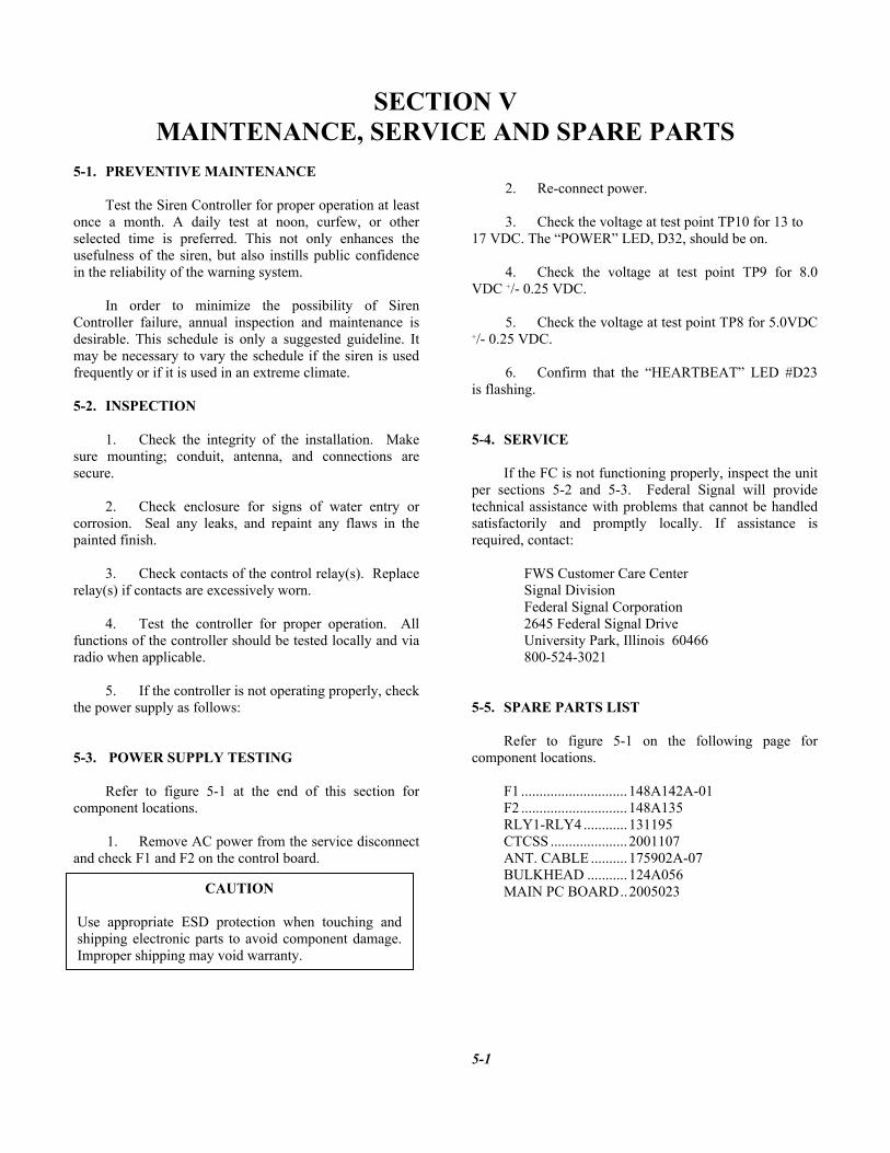
5-1. PREVENTIVE MAINTENANCE Test the Siren Controller for proper operation at least once a month. A daily test at noon, curfew, or other selected time is preferred. This not only enhances the usefulness of the siren, but also instills public confidence in the reliability of the warning system. In order to minimize the possibility of Siren Controller failure, annual inspection and maintenance is desirable. This schedule is only a suggested guideline. It may be necessary to vary the schedule if the siren is used frequently or if it is used in an extreme climate. 5-2. INSPECTION 1. Check the integrity of the installation. Make sure mounting; conduit, antenna, and connections are secure. 2. Check enclosure for signs of water entry or corrosion. Seal any leaks, and repaint any flaws in the painted finish. 3. Check contacts of the control relay(s). Replace relay(s) if contacts are excessively worn. 4. Test the controller for proper operation. All functions of the controller should be tested locally and via radio when applicable. 5. If the controller is not operating properly, check the power supply as follows: 5-3. POWER SUPPLY TESTING Refer to figure 5-1 at the end of this section for component locations. 1. Remove AC power from the service disconnect and check F1 and F2 on the control board.
2. Re-connect power.
3. Check the voltage at test point TP10 for 13 to 17 VDC. The “POWER” LED, D32, should be on. 4. Check the voltage at test point TP9 for 8.0 VDC +/- 0.25 VDC. 5. Check the voltage at test point TP8 for 5.0VDC +/- 0.25 VDC. 6. Confirm that the “HEARTBEAT” LED #D23 is flashing. 5-4. SERVICE If the FC is not functioning properly, inspect the unit per sections 5-2 and 5-3. Federal Signal will provide technical assistance with problems that cannot be handled satisfactorily and promptly locally. If assistance is required, contact: FWS Customer Care Center Signal Division Federal Signal Corporation 2645 Federal Signal Drive University Park, Illinois 60466 800-524-3021 5-5. SPARE PARTS LIST Refer to figure 5-1 on the following page for component locations. F1 .............................148A142A-01 F2 .............................148A135 RLY1-RLY4 ............131195 CTCSS .....................2001107 ANT. CABLE ..........175902A-07 BULKHEAD ...........124A056 MAIN PC BOARD..2005023
5-1
CAUTION Use appropriate ESD protection when touching andshipping electronic parts to avoid component damage.Improper shipping may void warranty.

Figure 5-1. FC Assembly Drawing
5-2
FEDERAL SIGNAL CORPORATION
FC SERIES SIREN CONTROLLER
INSTALLATION, OPERATION AND USER’S MANUAL
255294H 11/05 Copyright 2005 Federal Signal Corporation Printed in U.S.A. Price $15