PLANETARY HYDRAULIC WINCH PML · hydraulic counter-balance valve or holding valve is not required...
35
PMC 367 051117 INSTRUCTION AND PARTS MANUAL PL5 FREE FALL PLANETARY HYDRAULIC WINCH PML PULLMASTER WINCH CORPORATION 8247-130th Street, Surrey, B.C. V3W 7X4, Canada Telephone: 604-594-4444 Fax: 604-591-7332 Website: www.pullmaster.com E-mail: [email protected] READ THIS MANUAL BEFORE INSTALLING, OPERATING OR SERVICING THIS PRODUCT. THIS MANUAL CONTAINS IMPORTANT INFORMATION. MAKE THIS MANUAL AVAILABLE TO ALL PERSONS RESPONSIBLE FOR THE OPERATION, INSTALLATION, SERVICING AND MAINTENANCE OF THIS PRODUCT. THE LOGICAL CHOICE
Transcript of PLANETARY HYDRAULIC WINCH PML · hydraulic counter-balance valve or holding valve is not required...
PMC 367 051117
INSTRUCTION AND PARTS MANUAL
PL5 FREE FALLPLANETARY HYDRAULIC WINCH
PML
PULLMASTER WINCH CORPORATION8247-130th Street, Surrey, B.C. V3W 7X4, CanadaTelephone: 604-594-4444 Fax: 604-591-7332
Website: www.pullmaster.comE-mail: [email protected]
READ THIS MANUAL BEFORE INSTALLING, OPERATING ORSERVICING THIS PRODUCT. THIS MANUAL CONTAINS IMPORTANTINFORMATION. MAKE THIS MANUAL AVAILABLE TO ALL PERSONSRESPONSIBLE FOR THE OPERATION, INSTALLATION, SERVICINGAND MAINTENANCE OF THIS PRODUCT.
THE LOGICAL CHOICE
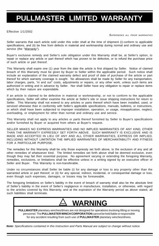
PULLMASTER LIMITED WARRANTY
Effective 1/1/2002SUPERSEDES ALL PRIOR WARRANTIES
Seller warrants that each article sold under this order shall at the time of shipment (i) conform to applicablespecifications, and (ii) be free from defects in material and workmanship during normal and ordinary use andservice (the “Warranty”).
Buyer’s exclusive remedy and Seller’s sole obligation under this Warranty shall be, at Seller’s option, torepair or replace any article or part thereof which has proven to be defective, or to refund the purchase priceof such article or part thereof.
This Warranty shall expire one (1) year from the date the article is first shipped by Seller. Notice of claimedbreach of this Warranty must be given by Buyer to Seller within the applicable period. Such notice shallinclude an explanation of the claimed warranty defect and proof of date of purchase of the article or partthereof for which warranty coverage is sought. No allowances shall be made by Seller for any transportation,labor charges, parts, “in and out” costs, adjustments or repairs, or any other work, unless such items areauthorized in writing and in advance by Seller. Nor shall Seller have any obligation to repair or replace itemswhich by their nature are expendable.
If an article is claimed to be defective in material or workmanship, or not to conform to the applicablespecifications, Seller will either examine the article at Seller’s site or issue shipping instructions for return toSeller. This Warranty shall not extend to any articles or parts thereof which have been installed, used, orserviced otherwise than in conformity with Seller’s applicable specifications, manuals, bulletins, or instructions,or which shall have been subjected to improper installation, operation, or usage, misapplication, neglect,overloading, or employment for other than normal and ordinary use and service.
This Warranty shall not apply to any articles or parts thereof furnished by Seller to Buyer’s specificationsand/or furnished by Buyer or acquired from others at Buyer’s request.
SELLER MAKES NO EXPRESS WARRANTIES AND NO IMPLIED WARRANTIES OF ANY KIND, OTHERTHAN THE WARRANTY EXPRESSLY SET FORTH ABOVE. SUCH WARRANTY IS EXCLUSIVE AND ISMADE AND ACCEPTED IN LIEU OF ANY AND ALL OTHER WARRANTIES, EXPRESS OR IMPLIED,INCLUDING WITHOUT LIMITATION THE IMPLIED WARRANTIES OF MERCHANTABILITY AND FITNESSFOR A PARTICULAR PURPOSE.
The remedies for this Warranty shall be only those expressly set forth above, to the exclusion of any and allother remedies of whatsoever kind. The limited remedies set forth above shall be deemed exclusive, eventhough they may fail their essential purpose. No agreement varying or extending the foregoing Warranty,remedies, exclusions, or limitations shall be effective unless in a writing signed by an executive officer ofSeller and Buyer. This Warranty is non-transferable.
Under no circumstances shall Seller be liable (i) for any damage or loss to any property other than thewarranted article or part thereof, or (ii) for any special, indirect, incidental, or consequential damage or loss,even though such expenses, damages, or losses may be foreseeable.
The foregoing limitations on Seller’s liability in the event of breach of warranty shall also be the absolute limitof Seller’s liability in the event of Seller’s negligence in manufacture, installation, or otherwise, with regardto the articles covered by this Warranty, and at the expiration of the Warranty period as above stated, allsuch liabilities shall terminate.
PULLMASTER planetary winches/drives are not designed for operations involving lifting or movingpersonnel. The PULLMASTER WINCH CORPORATION cannot be held liable or responsible
for any accident resulting from such use of PULLMASTER planetary winches/drives.
WARNING
Note: Specifications contained in this Instruction and Parts Manual are subject to change without notice.
PAGE 1
1. Do not install, operate or service winch beforereading and understanding manufacturer'sinstructions.
2. The winch described herein is not designedfor operations involving lifting or moving personnel.
3. Do not lift or carry loads over people.
4. Do not exceed recommended operatingpressure (psi) and operating volume (gpm).
5. Do not jerk the winch. Always smoothlyaccelerate and decelerate load.
6. Do not operate a damaged, noisy ormalfunctioning winch.
7. Do not leave a load suspended for anyextended period of time.
8. Never leave a suspended load unattended.
9. Winch should be maintained and operated byqualified personnel.
10. Inspect winch, rigging, mounting bolts andhoses before each shift.
11. Warm-up equipment before operating winch,particularly at low ambient temperatures.
12. Verify winch function by raising and lowering afull test load to a safe height before each shift.
13. Do not weld any part of the winch.
14. Verify gear lubrication and brake circulationsupply and return before operating winch.
15. Be sure of equipment stability beforeoperating winch.
16. Wear proper clothing to avoid entanglement inrotating machinery.
17. Always stand clear of the load.
FAILURE TO COMPLY WITH THE FOLLOWING SAFETYRECOMMENDATIONS AND LOCAL RULES ANDREGULATIONS WILL RESULT IN PROPERTY
DAMAGE, SEVERE INJURY OR DEATH.
Definition: Caution indicates a potentiallyhazardous situation which, if not avoided mayresult in minor or moderate injury.
Definition: Warning indicates a potentiallyhazardous situation which, if not avoided couldresult in death or serious injury.
Definition: Danger indicates a potentiallyhazardous situation which, if not avoided willresult in death or serious injury.
18. Use only recommended hydraulic oil and gearlubricant.
19. Keep hydraulic system clean and free fromcontamination at all times.
20. Maintain winch and equipment in good operatingcondition. Perform scheduled maintenance regularly.
21. Keep hands clear when winding wire rope onto thewinch drum.
22. Do not use the wire rope as a ground for welding.
23. Rig the winch carefully. Ensure that the wire ropeis properly anchored to the correct cable anchor slot atthe cable drum.
24. Do not lift a load with a twisted, kinked ordamaged wire rope.
25. Consult wire rope manufacturer for size, type andmaintenance of wire rope.elen
26. Maintain five wraps of wire rope on the cabledrum at all times.
27. In case of a power failure or breakdown leading toan unexpected stop of the hydraulic power circuit,stand clear of the area and the load being hoisted,take the necessary precautions to prevent access toarea where the load is halted.
28. The noise level of the winch is 90 dBA measuredon a distance of 1.00 meter, 1.60 meters high. Themeasuring equipment used was: Realistic #42-3019.
29. Clean up any oil spillage immediately.
30. Wear proper clothing and personal protectionequipment such as, footwear, safety goggles and ahard hat. Read manual first.
367
SAFETY RECOMMENDATIONS
PULLMASTER planetary hydraulic winches are made for hoisting and lowering loads and are to be operated by trainedand professional personnel. They are not designed for operations involving lifting or moving personnel. The winchesare powered by hydraulic power. The ropes / cables for hoisting operations are not supplied by PULLMASTER WINCHCORPORATION. The winches are always assembled in an application, they do not function as an independentmachine and it is not allowed to use them as such.elen
The winches are to be used within the specifications as listed in the manual under “SPECIFICATIONS”. Other useas foreseen in the functional description of the hydraulic winch is not allowed without written permission fromPULLMASTER WINCH CORPORATION.
DANGER
051117
PAGE 2
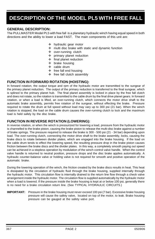
GENERAL DESCRIPTION:The PULLMASTER Model PL5 with free fall is a planetary hydraulic winch having equal speed in bothdirections and the ability to lower a load FAST. The main components of this unit are:
✛ hydraulic gear motor✛ multi disc brake with static and dynamic function✛ over-running clutch✛ primary planet reduction✛ final planet reduction✛ brake housing✛ cable drum✛ free fall end housing✛ free fall clutch assembly
FUNCTION IN FORWARD ROTATION (HOISTING):In forward rotation, the output torque and rpm of the hydraulic motor are transmitted to the sungear ofthe primary planet reduction. The output of the primary reduction is transferred to the final sungear, whichis splined to the primary planet hub. The final planet assembly is locked in place by the free fall clutchand does not rotate, so the rotation is transmitted to the cable drum by the final drive planet gears. In forwardrotation, or when a load is lifted, an over-running clutch, which connects the motor drive shaft to theautomatic brake assembly, permits free rotation of the sungear, without effecting the brake. Pressurerequired to rotate the drum at full speed without load may vary up to 300 psi (21 bar). When the winchrotation is stopped, the load on the cable drum causes the over-running clutch to lock and the maximumload is held safely by the disc brake.
FUNCTION IN REVERSE ROTATION (LOWERING):In reverse rotation, or when the winch is pressurized for lowering a load, pressure from the hydraulic motoris channelled to the brake piston, causing the brake piston to release the multi-disc brake against a numberof brake springs. The pressure required to release the brake is 300 - 500 psi (21 - 34 bar) depending uponload. The over-running clutch, connecting the motor drive shaft to the brake assembly, locks, causing thebrake discs to rotate between divider plates, which are engaged into the brake housing. If the load onthe cable drum tends to effect the lowering speed, the resulting pressure drop in the brake piston causesfriction between the brake discs and the divider plates. In this way, a completely smooth paying out speedcan be achieved in a stepless operation by modulation of the winch control valve handle. When the controlvalve handle is returned to neutral position, pressure drops and the disc brake applies automatically. Ahydraulic counter-balance valve or holding valve is not required for smooth and positive operation of theautomatic brake.
During the lowering operation of the winch, the friction created by the brake discs results in heat. This heatis dissipated by the circulation of hydraulic fluid through the brake housing, supplied internally throughthe hydraulic motor. This circulation flow is internally drained to the return line flow through a check valvearrangement inside the hydraulic motor. The circulation flow is supplied automatically by the hydraulic motorwhen a load is lowered. If the pressure inside the brake housing is kept at or below 100 psi, generally thereis no need for a brake circulation return line. (See TYPICAL HYDRAULIC CIRCUITS.)
IMPORTANT: Pressure in the brake housing must never exceed 100 psi (7 bar). Excessive brake housingpressure will cause the safety valve, located on top of the motor, to leak. Brake housingpressure can be gauged at the safety valve port.
DESCRIPTION OF THE MODEL PL5 WITH FREE FALL
367 050906

PAGE 3
RE-ENGAGING FREE FALL CLUTCH WHILE LOAD IS DROPPINGCAUSES SHOCK LOADS AND WILL LEAD TO CABLE FAILURE,
PROPERTY DAMAGE, SEVERE INJURY OR DEATH. INTERLOCKHYDRAULIC CONTROL TO PREVENT RE-ENGAGING FREE FALL
CLUTCH WHILE LOAD IS DROPPING.
DANGER
ALWAYS ENSURE COMPLIANCE WITH ANY NATIONAL OR LOCALSAFETY CODES AND REGULATIONS REGARDING THE USE OF FREE
FALL WINCHES PRIOR TO OPERATION OF THIS UNIT.
EMERGENCY FREE FALL:The emergency free fall is used for a full release of a suspended load up to the maximum load capacityof the PULLMASTER Model PL5 planetary winch with free fall. Upon activating the emergency freefall function the load will drop and must be allowed to fall to its end travel without re-engagement.
FUNCTION OF THE EMERGENCY FREE FALL:When the PULLMASTER Model PL5 planetary winch with free fall is actuated for emergency free fall,hydraulic pressure is supplied to the clutch piston, compressing a series of springs to release the multi-disc clutch. This effectively disconnects the cable drum from the gear train of the winch to drop thesuspended load. Minimum load 100 lbs (45 kg) is required to overcome the resistance in free fall mode.
IMPORTANT: Pressure in the free fall end housing must never exceed 10 psi (.7 bar).Free fall end housing pressure can be gauged at the circulation inlet port.
WARNING
DESCRIPTION OF THE MODEL PL5 WITH FREE FALL
367 050906
PAGE 4
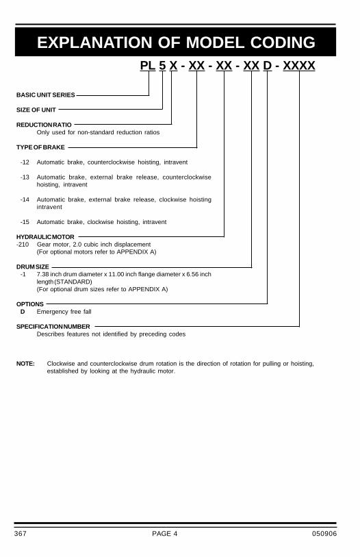
BASIC UNIT SERIES
SIZE OF UNIT
REDUCTION RATIOOnly used for non-standard reduction ratios
TYPE OF BRAKE
-12 Automatic brake, counterclockwise hoisting, intravent
-13 Automatic brake, external brake release, counterclockwisehoisting, intravent
-14 Automatic brake, external brake release, clockwise hoistingintravent
-15 Automatic brake, clockwise hoisting, intravent
HYDRAULIC MOTOR-210 Gear motor, 2.0 cubic inch displacement
(For optional motors refer to APPENDIX A)
DRUM SIZE-1 7.38 inch drum diameter x 11.00 inch flange diameter x 6.56 inch
length (STANDARD)(For optional drum sizes refer to APPENDIX A)
OPTIONSD Emergency free fall
SPECIFICATION NUMBERDescribes features not identified by preceding codes
PL 5 X - XX - XX - XX D - XXXX
EXPLANATION OF MODEL CODING
NOTE: Clockwise and counterclockwise drum rotation is the direction of rotation for pulling or hoisting,established by looking at the hydraulic motor.
367 050906
PAGE 5
CABLE DRUM SIZES:Aside from the standard drum sizes listed in APPENDIX A, the PULLMASTER Model PL5 planetary winchwith free fall can be supplied with optional drums to accommodate large wire rope storage capacity.
DRUM GROOVING:Cable drums for the PULLMASTER Model PL5 planetary winch with free fall can be grooved. Where thisoption is a requirement, it is necessary to state the size of wire rope which is to be used with the winch.
OPTIONAL GEAR SECTION FOR THE HYDRAULIC MOTOR:The performance of the standard PULLMASTER Model PL5 planetary winch with free fall may be changedby using a different displacement motor.(See APPENDIX A for performance information.)
HYDRAULIC MOTORS FOR HIGH PRESSURE HYDRAULIC SYSTEMS:The operating pressure of the PULLMASTER Model PL5 planetary winch with free fall and standard gearmotor is limited to 2100 psi (145 bar). For hydraulic systems operating with higher hydraulic pressure, thewinch can be supplied with a hydraulic piston motor which will provide for the same basic performancein terms of line pull and line speed capacity.(Contact the factory for this requirement.)
The PULLMASTER WINCH CORPORATION will consider other options for quantity requirements.
CLOCKWISE ROTATION:The drum rotation of the standard PULLMASTER Model PL5 planetary winch with free fall is counterclockwisefor hoisting, when looking at the hydraulic motor of the winch. Drum rotation for clockwise hoisting directionis available as an option.
EXTERNAL BRAKE RELEASE:PULLMASTER planetary winches can be supplied with an external brake release which permits releaseof the automatic disc brake from an external pressure source.
DANGER
OPTIONS
FAILURE TO PROPERLY VENT EXTERNAL BRAKE RELEASE PORTWILL TRAP BRAKE PRESSURE AND ALLOW THE LOAD TO DROP,
CAUSING PROPERTY DAMAGE, SEVERE INJURY OR DEATH.WINCHES SUPPLIED WITH EXTERNAL BRAKE RELEASE OPTION
MUST BE CONNECTED ACCORDING TO "TYPICAL HYDRAULIC CIRCUITS".
367 050906

PAGE 6
Performance specifications are based on standard hydraulic motor, gear ratio and cable drum with 7/16inch diameter wire rope. See APPENDIX A for performance of available options.
CABLE DRUM DIMENSIONS (STANDARD DRUM):Barrel Diameter 7.38 in 187 mmFlange Diameter 11.00 in 279 mmBarrel Length 6.56 in 167 mm
CABLE STORAGE CAPACITY:Size of wire rope 1/4 in 348 ft 106 m
5/16 in 218 ft 67 m 3/8 in 157 ft 48 m 7/16 in 110 ft 34 m 1/2 in 100 ft 31 m
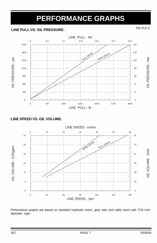
MAXIMUM OPERATING PRESSURE: 2100 psi 145 bar
MAXIMUM OPERATING VOLUME: 24 (US) gpm 91 l/min
MINIMUM OPERATING VOLUME: 6 (US) gpm 23 l/min
DRUM TORQUE AT MAXIMUM PRESSURE: 17,578 lb-in 1986 Nm
DRUM RPM AT MAXIMUM VOLUME: 66 rpm
LINE PULL AT MAXIMUM PRESSURE:Bare drum 4500 lb 20.0 kNFull drum 3328 lb 14.8 kN
LINE SPEED AT MAXIMUM VOLUME:Bare drum 135 fpm 41 m/minFull drum 183 fpm 56 m/min
PERMISSIBLE SYSTEM BACK PRESSUREAT MOTOR RETURN PORT: 65 psi 4.5 bar
PERMISSIBLE PRESSURE IN BRAKE HOUSING(GAUGED AT SAFETY VALVE PORT): 100 psi 7 bar
PERMISSIBLE PRESSUREAT FREE FALL CIRCULATION SUPPLY PORT: 10 psi 0.7 bar
LUBRICATING OIL: Volume required (-1 drum): 0.3 (US) gal (1.1 litre)Volume required (-6 drum): 0.5 (US) gal (1.9 litre)
Refer to RECOMMENDATIONS for viscosity and instructions.
SPECIFICATIONS
367 050906
PAGE 7
7620
6116
4512
308
154
1241800
1041500
831200
62900
41600
21300
BARE DRUM
FULL DRUM
LINE PULL - kN
LINE SPEED - m/min
FULL DRUM
BARE DRUM
2100
0
24
0
450037503000225015007500
0 3.3 6.7 10.0 13.3 16.7 20.0
145
0
LINE PULL - lb
OIL
PR
ES
SU
RE
- p
si
OIL
PR
ES
SU
RE
- b
ar
330 66 99 132 165 198
0 10 20 30 40 50 60
0
LINE SPEED - fpm
91
OIL
VO
LUM
E -
(U
S)g
pm
OIL
VO
LUM
E -
l/m
in
PG-PL5-C
PERFORMANCE GRAPHS
Performance graphs are based on standard hydraulic motor, gear ratio and cable drum with 7/16 inchdiameter rope.
LINE PULL VS. OIL PRESSURE:
LINE SPEED VS. OIL VOLUME:
367 050906
PAGE 8
HC-PL5-D-S1-A
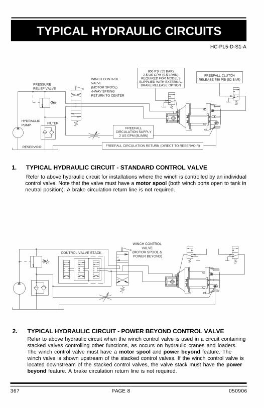
2. TYPICAL HYDRAULIC CIRCUIT - POWER BEYOND CONTROL VALVERefer to above hydraulic circuit when the winch control valve is used in a circuit containingstacked valves controlling other functions, as occurs on hydraulic cranes and loaders.The winch control valve must have a motor spool and power beyond feature. Thewinch valve is shown upstream of the stacked control valves. If the winch control valve islocated downstream of the stacked control valves, the valve stack must have the powerbeyond feature. A brake circulation return line is not required.
TYPICAL HYDRAULIC CIRCUITS
BRAKE RELEASE OPTIONSUPPLIED WITH EXTERNAL
REQUIRED FOR MODELS2.5 US GPM (9.5 L/MIN)
800 PSI (55 BAR)
RELEASE 750 PSI (52 BAR)FREEFALL CLUTCH
FREEFALL CIRCULATION RETURN (DIRECT TO RESERVOIR)
2 US GPM (8L/MIN)CIRCULATION SUPPLY
FREEFALL
FILTERPUMPHYDRAULIC
RESERVOIR
RETURN TO CENTER4-WAY SPRING(MOTOR SPOOL)VALVEWINCH CONTROL
RELIEF VALVEPRESSURE
CONTROL VALVE STACK POWER BEYOND)(MOTOR SPOOL &
VALVEWINCH CONTROL
1. TYPICAL HYDRAULIC CIRCUIT - STANDARD CONTROL VALVE
Refer to above hydraulic circuit for installations where the winch is controlled by an individualcontrol valve. Note that the valve must have a motor spool (both winch ports open to tank inneutral position). A brake circulation return line is not required.
367 050906

PAGE 9
HC-PL5-D-S1-A
3. TYPICAL HYDRAULIC CIRCUIT - STACKED CONTROL VALVE
Refer to above hydraulic circuit when the winch control valve is one of several stacked controlvalves and has a cylinder spool (winch ports blocked in neutral position). In this configuration,the safety valve must be replaced with a circulation return line plumbed directly to the reservoir.The brake circulation return line cannot be connected to a common return line.
IMPORTANT: For proper function of the winch in any circuit, the return line back pressuremeasured at the motor return port, the brake housing pressure measured at thesafety valve and the free fall end housing pressure measured at the circulationinlet port must not exceed pressures per SPECIFICATIONS.
TYPICAL HYDRAULIC CIRCUITS
(CYLINDER SPOOL)VALVE
WINCH CONTROL TO RESERVOIR)
(MUST GO DIRECTBRAKE CIRCULATION RETURN
CONTROL VALVE STACK
367 050906

PAGE 10
HYDRAULIC FLUID:The hydraulic fluid selected for use with PULLMASTERplanetary winches should be a high grade, petroleumbased fluid with rust, oxidation and wear resistance.Fluid cleanliness and operating viscosity are critical towinch reliability, efficiency and service life.
For optimum performance, the recommended viscosityrange at operating temperature is 81 - 167 SUS (16 - 36CS). For extreme operating conditions of short duration,the maximum viscosity range of 58 - 4635 SUS (10 - 1000CS) should not be exceeded.
The recommended hydraulic fluid temperature operatingrange is 80 - 150F (27 - 66C). For extreme operatingconditions of short duration, the maximum temperaturerange of -5 - 180F (-21 - 82C) should not be exceeded.
LUBRICATION:The winch gear train requires oil bath lubrication. Thewinch is shipped from the factory without lubricating oil.
IMPORTANT: ADD LUBRICATING OIL THROUGH THECABLE DRUM FILL PORT BEFORERUNNING WINCH.
Refer to INSTALLATION DIMENSIONS for location oflubricating oil fill port. For normal operating temperatureuse SAE 90 lubricating oil in the cable drum: 0.3 gallon(1.2 liters) for -1 drum and 0.5 gallon (2 liters) for -6 drum.Consult lubricating oil supplier or factory for temperaturesbeyond normal operating range.
HYDRAULIC PUMP:For maximum performance of the PULLMASTER planetarywinch the hydraulic pump must supply the maximum flowof hydraulic fluid at the hydraulic pressure stated inSPECIFICATIONS.
EMERGENCY FREE FALL CONTROL VALVE:A two-position, three-way, detented valve is required toactuate emergency free fall. Emergency free fall is usedto fully release a load up to the maximum capacity of thewinch. The valve is not required to meter oil supply. Inneutral position, the free fall clutch release port must bevented to reservoir.
RECOMMENDATIONS
DANGER
RE-ENGAGING FREE FALL CLUTCH WHILELOAD IS DROPPING CAUSES SHOCK LOADS
AND WILL LEAD TO CABLE FAILURE,PROPERTY DAMAGE, SEVERE INJURY ORDEATH. INTERLOCK HYDRAULIC CONTROL
TO PREVENT RE-ENGAGING FREE FALLCLUTCH WHILE LOAD IS DROPPING.
HYDRAULIC CONTROL VALVE:A standard control valve used for operating PULLMASTERplanetary winches must have a four-way, spring return toneutral feature, which provides for open flow from thepressure ports of the winch to the reservoir in neutralposition of the control (motor spool). It is important to pointout that good speed control, especially when lowering aload, depends on the "metering" characteristics of thecontrol valve. The better the oil flow is "metered", thebetter will be the speed control.
HYDRAULIC PRESSURE RELIEF:The hydraulic circuit for the PULLMASTER planetarywinch requires a pressure relief set at the operatingpressure (see SPECIFICATIONS). Usually, a pressurerelief is part of the hydraulic control valve. Where thisis not the case, a separate pressure relief valve must beinstalled and set at the recommended maximum pressure.
HYDRAULIC RESERVOIR:It is recommended that the hydraulic reservoir hassufficient capacity to provide good heat dissipation inorder to prevent over-heating of the hydraulic fluid. Thehydraulic reservoir should be made from clean and scale-free material to prevent contamination of the hydraulicfluid. In order to prevent air from being mixed with thehydraulic fluid, the reservoir should have an over-flowbaffle separating the return lines from the suction line andall return lines should enter the reservoir below the fluidlevel. The reservoir should be mounted close to and abovethe hydraulic pump in a location which provides for freeair circulation around the reservoir.
HYDRAULIC FILTER:Consult hydraulic component manufacturer forrecommendation. Generally, 5 to 10 micron filters areacceptable. In order to prevent accidental stoppage ofthe return line flow, the filter should have a by-passfeature.
HYDRAULIC HOSES:The following hydraulic hose with suitable fittings isrecommended for the PULLMASTER Model PL5 planetarywinch with free fall.
Pressure lines: SAE 100R2-14 or betterCirculation return line: SAE 100R6-8 or betterCirculation supply line: SAE 100R6-4 or betterFree fall release line: SAE 100R2-4 or better
USE OF AN E STOP:(FOR EUROPEAN MACHINERY DIRECTIVE APPLICATIONS)The use of an E stop (emergency) is mandatory in thecontrols circuit. The E stop is to be placed in the operatorscontrol panel. The E stop has to be designed and placedin line with EN 60204 and EN 418.
367 050906
PAGE 11
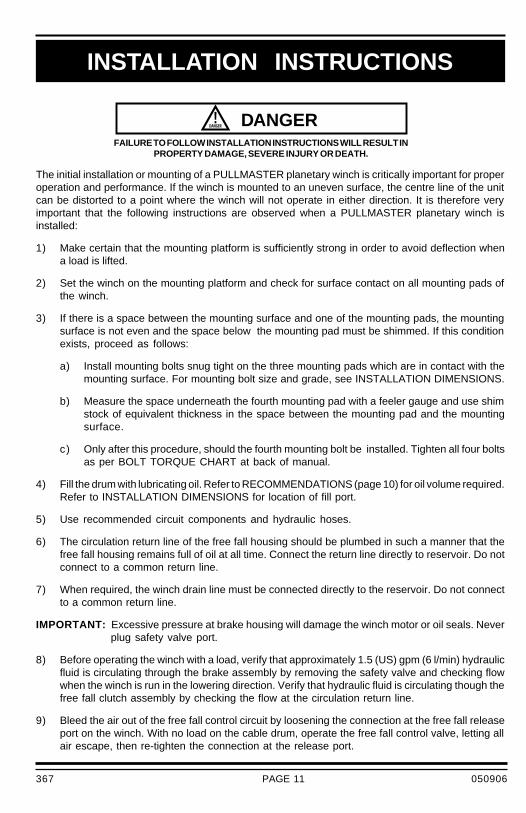
The initial installation or mounting of a PULLMASTER planetary winch is critically important for properoperation and performance. If the winch is mounted to an uneven surface, the centre line of the unitcan be distorted to a point where the winch will not operate in either direction. It is therefore veryimportant that the following instructions are observed when a PULLMASTER planetary winch isinstalled:
1) Make certain that the mounting platform is sufficiently strong in order to avoid deflection whena load is lifted.
2) Set the winch on the mounting platform and check for surface contact on all mounting pads ofthe winch.
3) If there is a space between the mounting surface and one of the mounting pads, the mountingsurface is not even and the space below the mounting pad must be shimmed. If this conditionexists, proceed as follows:
a) Install mounting bolts snug tight on the three mounting pads which are in contact with themounting surface. For mounting bolt size and grade, see INSTALLATION DIMENSIONS.
b) Measure the space underneath the fourth mounting pad with a feeler gauge and use shimstock of equivalent thickness in the space between the mounting pad and the mountingsurface.
c) Only after this procedure, should the fourth mounting bolt be installed. Tighten all four boltsas per BOLT TORQUE CHART at back of manual.
4) Fill the drum with lubricating oil. Refer to RECOMMENDATIONS (page 10) for oil volume required.Refer to INSTALLATION DIMENSIONS for location of fill port.
5) Use recommended circuit components and hydraulic hoses.
6) The circulation return line of the free fall housing should be plumbed in such a manner that thefree fall housing remains full of oil at all time. Connect the return line directly to reservoir. Do notconnect to a common return line.
7) When required, the winch drain line must be connected directly to the reservoir. Do not connectto a common return line.
IMPORTANT: Excessive pressure at brake housing will damage the winch motor or oil seals. Neverplug safety valve port.
8) Before operating the winch with a load, verify that approximately 1.5 (US) gpm (6 l/min) hydraulicfluid is circulating through the brake assembly by removing the safety valve and checking flowwhen the winch is run in the lowering direction. Verify that hydraulic fluid is circulating though thefree fall clutch assembly by checking the flow at the circulation return line.
9) Bleed the air out of the free fall control circuit by loosening the connection at the free fall releaseport on the winch. With no load on the cable drum, operate the free fall control valve, letting allair escape, then re-tighten the connection at the release port.
FAILURE TO FOLLOW INSTALLATION INSTRUCTIONS WILL RESULT INPROPERTY DAMAGE, SEVERE INJURY OR DEATH.
DANGER
INSTALLATION INSTRUCTIONS
367 050906
PAGE 12
CABLE ANCHOR
CABLE ANCHOR SLOT
After the PULLMASTER planetary winch has been installed in accordance with the INSTALLATIONINSTRUCTIONS, the wire rope can be fastened to the cable drum.
IMPORTANT: Refer to manufacturer’s handling, inspection and maintenance recommendations toavoid potential accidents. For selection of ropes, etc. please check following productstandards: DIN 15020, prEN818-1/9, prEN 1492-1/2, prEN 1677-1/3 and otherrelevant product standards.
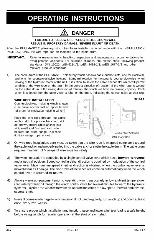
1) The cable drum of the PULLMASTER planetary winch has two cable anchor slots, one for clockwiseand one for counterclockwise hoisting. Standard rotation for hoisting is counterclockwise whenlooking at the hydraulic motor of the unit. It is critical to select the cable anchor slot which will permitwinding of the wire rope on the drum in the correct direction of rotation. If the wire rope is woundon the cable drum in the wrong direction of rotation, the winch will have no braking capacity. Eachwinch is shipped from the factory with a label on the drum, indicating the correct cable anchor slot.
FAILURE TO FOLLOW OPERATING INSTRUCTIONS WILLRESULT IN PROPERTY DAMAGE, SEVERE INJURY OR DEATH.
2) On wire rope installation, care must be taken that the wire rope is wrapped completely aroundthe cable anchor and properly pulled into the cable anchor slot in the cable drum. The cable drumrequires minimum of 5 wraps of wire rope for safety.
3) The winch operation is controlled by a single control valve lever which has a forward , a reverseand a neutral position. Speed control in either direction is obtained by modulation of the controlvalve lever. Maximum line speed in either direction is obtained when the control valve lever ismoved as far as it can go. The disc brake of the winch will come on automatically when the winchcontrol lever is returned to neutral .
4) Always warm up equipment prior to operating winch, particularly in low ambient temperature.Circulate hydraulic oil through the winch control valve for several minutes to warm the hydraulicsystems. To prime the winch with warm oil, operate the winch at slow speed, forward and reverse,several times.
5) Prevent corrosion damage to winch interior. If not used regularly, run winch up and down at leastonce every two weeks.
6) To ensure proper winch installation and function, raise and lower a full test load to a safe heightbefore using winch for regular operation at the start of each shaft.
WIRE ROPE INSTALLATIONCounterclockwise hoisting winch shown.(Use cable anchor slot on opposite side of drum for clockwise hoisting winch.)
Feed the wire rope through the cableanchor slot. Loop rope back into slotas shown. Insert cable anchor intoslot, small end first and long sidenearest the drum flange. Pull ropetight to wedge rope in slot.
DANGER
OPERATING INSTRUCTIONS
SI1013
367 051117
PAGE 13
OPERATING INSTRUCTIONS7) Shift the emergency free fall control valve to pressurize the free fall clutch release port, effectively
disconnecting the cable drum from the gear train and dropping the load. Free fall speed dependson size of the load. The minimum load that will overcome the resistance in free fall mode isapproximately 100 lb (45 kg).
RE-ENGAGING FREE FALL CLUTCH WHILE LOAD IS DROPPINGCAUSES SHOCK LOADS AND WILL LEAD TO CABLE FAILURE,
PROPERTY DAMAGE, SEVERE INJURY OR DEATH. INTERLOCKHYDRAULIC CONTROL TO PREVENT RE-ENGAGING
FREE FALL CLUTCH WHILE LOAD IS DROPPING.
DANGER
If, after a new installation, the winch does not function properly, refer to the TROUBLESHOOTINGsection of this manual.
367 050906

PAGE 14
TROUBLE SHOOTING
Winch will not produce line pull at maximumpressure as listed in SPECIFICATIONS.
PROBABLE CAUSEFAILURE
Winch will not produce line speed at maximumvolume as listed in SPECIFICATIONS.
Winch will not reverse.
a) Winch is mounted to an uneven surface.(See INSTALLATION INSTRUCTIONS.)
b) Cable sheaves or block purchase operated with thewinch are not turning freely.
c) Damage or wear in the hydraulic motor.d) The relief valve pressure may be set too low.
(See SPECIFICATIONS for maximum operating pressure.)e) Excessive back pressure in the hydraulic system.
a) Winch is mounted to an uneven surface.(See INSTALLATION INSTRUCTIONS.)
b) Cable sheaves or block purchase operated with thewinch are not turning freely.
c) Damage or wear in the hydraulic motor.d) Excessive back pressure in the hydraulic system.
a) Leakage out of the brake piston prevents the disc brakefrom being released against the brake springs. This iscaused by damage to the O-rings on the brake pistonor connecting tube.
b) Insufficient hydraulic pressure.(See SPECIFICATIONS for minimum operating pressure.)
c) Winch is mounted to an uneven surface.(See INSTALLATION INSTRUCTIONS.)
d) Hydraulic pressure is not reaching the brake piston dueto plugged brake release passage.
GENERAL:In most cases, when the hydraulic winch does not perform satisfactorily, the cause for malfunction is foundsomewhere in the hydraulic circuit. Before the winch is removed from its mounting and disassembled, allof the hydraulic circuit components should be checked for proper function.
IMPORTANT:
The hydraulic oil volume relates to the line speed or rpm of the winch.Therefore, if the winch does not produce the specified maximum rated line speed or drum rpm, a lossof hydraulic flow somewhere in the hydraulic circuit can be analysed. If this condition exists, install aflow meter into the hydraulic circuit to check the volume of oil supplied to the pressure port of the hydraulicwinch motor when the winch control is completely opened. The flow meter should indicate the maximumoperating volume. If this test indicates a loss of hydraulic flow, check the hydraulic pump, the relief valveand the control valve. If the pump is driven by V-belts, check for belt slippage.
The hydraulic pressure relates to the pulling capacity of the winch.If the winch will not produce the specified maximum line pull, install a pressure gauge in the pressureline leading to the hoisting port on the hydraulic winch motor. Stall the winch to prevent rotation of thedrum and then open the control valve. Check the hydraulic pressure reading of the installed pressuregauge. If the pressure reads below the specified maximum operating pressure, look for trouble in thehydraulic pump, the relief valve and the control valve. If the hydraulic pump is driven by V-belts, checkfor belt slippage. When checking oil pressure and volume in the hydraulic circuit, make sure that thehydraulic reservoir is filled to the top level and the hydraulic pump is running at maximum operating rpm.
Only after the hydraulic system has been checked and found to be in order, use the following indicationsfor probable causes of failure in the winch:
367 050906

PAGE 15
TROUBLE SHOOTING CONTINUED
Refer to the SERVICE INSTRUCTIONS if it becomes necessary to disassemble the Model PL5winch with free fall.
a) Brake plates or divider plates have been damagedby contamination in the hydraulic fluid or lack ofcirculation flow in the brake housing.
b) Brake piston or clutch piston seize because ofcontamination in the hydraulic fluid.
c) Excessive back pressure in the return line of thehydraulic system causes the brake to release.
d) Control valve has incorrect spool which trapshydraulic pressure in the brake piston when thecontrol valve handle is returned to neutral position.For proper function of the automatic brake, bothpressure ports of the winch must be open to thereservoir in neutral position of the control valve.
e) Wire rope is fastened to the incorrect cable anchorslot.
f) Over-running clutch is damaged or surface whereover-running clutch engages on motor drive shaftis worn or indented.
g) Failure to vent free fall clutch or optional externalbrake release may cause winch load to slip.
a) Pump does not supply sufficient flow. Pump rpmmust be maintained at normal operating speed whena load is lowered.
b) Brake is running too hot. This is caused by acomplete lack of, or insufficient, circulation flow.
c) Control valve for the winch operation has poormetering characteristics.
d) Damaged brake plates or divider plates.e) Over-running clutch is damaged or surface where
over-running clutch engages on motor drive shaftis worn or indented.
f) Air has mixed with hydraulic oil resulting in foamyoil.
a) Insufficient pressure or flow supplied to free fallport. Check TYPICAL HYDRAULIC CIRCUITS forpressure and volume requirements.
b) O-ring seals in clutch piston are damaged.c) Insufficient load on the wire rope. A minimum of 100
lb (45 kg) is required to drop a load in free fall.
a) Oil leaks from the motor adaptor are caused by adamaged O-ring seal on the motor adaptor.
b) Oil leaks occurring between the cable drum flangeand free fall housing is caused by excessivepressure in the free fall housing or brake housing.Oil leak occurring between the cable drum flangeand brake housing is caused by excessive pressurein the brake housing.
PROBABLE CAUSEFAILURE
Brake will not hold.
Oil leaks.
Brake vibrates when lowering a load.
Free fall clutch cannot be disengaged.
367 050906
PAGE 16
GENERAL:
Before disassembling the PULLMASTER Model PL5 planetary winch with free fall, read and understand the followinginstructions.
Replace expendable parts such as O-rings and oil seals when reassembling the winch. Have a winch seal kit (PartNo. 23418) on hand before the unit is disassembled. If motor is to be serviced, have on a hand motor seal kit (PartNo. 24227).
NOTE: Backup washers may be included with seal kit. Install with oil seals as per instructions. If not presentin seal kit, the oil seals supplied do not require backup washers.
Disconnect all hydraulic hoses, remove the winch from its mounting and relocate to a clean working area, similarto one used for service work on any other hydraulic component. Special tools are not required to service the winch.Adjustments and calibrations are not required.
All parts, as they are removed from the winch assembly, should be inspected for wear and damage. Worn or damagedparts must be replaced. Thoroughly clean parts before reassembly. Do not use solvent to clean the brake frictionplates. During reassembly, lubricate all O-rings and oil seals with grease before installation.
The following SERVICE INSTRUCTIONS refer to part descriptions and item numbers which appear in the groupdrawings.
DISASSEMBLYREMOVAL OF FREE FALL ASSEMBLY:If the brake, primary or final drives require service, or if a general inspection overhaul is required, proceed toREMOVAL OF HYDRAULIC MOTOR ASSEMBLY. If specific service is required to correct a malfunction at the freefall end, remove the free fall assembly as follows:
1) Remove pipe plug, item 101, from free fall end housing, item 240, to drain lubricating oil from free fall end housing.
2) With winch sitting flat on its mounting pads, remove four capscrews, item 555, and lockwashers, item 553,which connect free fall housing, item 200, to tie bars, item 556.
3) Support cable drum, item 500, and withdraw free fall end housing, item 240, until spline of connecting shaft,item 220, is clear of cable drum.
4) Remove pipe plug, item 101, from free fall end housing, item 240, to drain oil from free fall assembly interior.
5) Stand free fall assembly on its end, with connecting shaft, item 220, vertical.
6) Proceed to DISASSEMBLY OF FREE FALL ASSEMBLY.
REMOVAL OF HYDRAULIC MOTOR ASSEMBLY:
1) Before removing hydraulic motor, refer to page 22 drawing # SI1043 and tick mark the position of the hydraulic
motor to facilitate reassembly.
2) Remove four capscrews, item 931, and lockwashers, item 933, from the motor adaptor, item 900. Brake springs,item 752, apply pressure against inside of motor adaptor, therefore it is recommended that capscrews areunscrewed, one turn at a time, until spring pressure has been released. The complete motor assembly, includingmotor adaptor, can now be removed from brake housing assembly.
3) Remove and discard two O-rings, item 801 and item 707. (O-ring, item 801, seals pressure transfer hole forautomatic brake release and is situated on flange of brake housing.)
DISASSEMBLY OF HYDRAULIC MOTOR ASSEMBLY:
If service or repair work requires access to interior of brake housing, hydraulic motor should not be disassembled.If problem has been analysed to be in hydraulic motor, proceed with disassembly as follows:
1) Remove four hex capscrews, item 951, together with lockwashers, item 953, from motor assembly.
SERVICE INSTRUCTIONS
367 050906

PAGE 17
SERVICE INSTRUCTIONS CONTINUED
IMPORTANT: Failure to exercise care when removing motor port end cover or gear housing could permanentlydamage machined surfaces of motor components. Take care not to damage machined surfaces ofmotor components at disassembly.
2) Remove port end cover, item 871, from gear housing, item 860.
3) Remove gear set, item 881 and item 882 and thrust blocks, item 885.
4) Remove and discard channel seals, item 887 and item 888 and backup seals, item 897.
5) Carefully pry gear housing, item 860, off of motor adaptor, item 900. Dowel pins, item 865, may stay in gear housing.
6) Discard section seals, item 869.
Section seals, channel seals and backup seals in hydraulic motor assembly are not part of winch seal kit. Seal kitfor hydraulic motor can be ordered from factory under Part No. 24227.
DISASSEMBLY OF BRAKE HOUSING ASSEMBLY:Disassemble brake housing assembly as follows:
1) Remove ten brake springs, item 752. Examine springs for damage and measure overall length. Overall springlength should be 1.25 inch. Springs measuring less than 1.19 inch should be replaced.
2) Pull brake piston, item 750, out of brake housing, item 700.
3) Remove and discard O-rings, item 751 and 753.
4) Thoroughly inspect brake piston outer diameters and brake housing inner bores for scoring caused by hydraulicfluid contamination. Minor surface damage may be repaired by polishing with a fine emery cloth.
5) Remove circlip, item 727, from primary sungear, item 440. Remove brake hub, item 720, sprag clutch, item 723,and sprag clutch aligners, item 722, from primary sungear.
DAMAGED FRICTION OR DIVIDER PLATES WILL REDUCE BRAKING CAPACITY AND ALLOW THELOAD TO DROP, CAUSING PROPERTY DAMAGE, SEVERE INJURY OR DEATH. SOLVENT MAY
DAMAGE THE FRICTION PLATES. DO NOT USE SOLVENT TO CLEAN THE FRICTIONPLATES. PERFORM THOROUGH INSPECTION AND, IF NECESSARY,
REPLACE FRICTION AND DIVIDER PLATES AS A SET.
6) Remove five friction plates, item 716, and six divider plates, item 713, and inspect for damage or wear. Platesshould be flat and smooth. Plates should not show heat discoloration. Paper material on friction plates shouldbe intact and grooved. If any damage is detected, replace friction and divider plates as a set (winches may containoptional metallic friction plates).
7) Remove brake spacer, item 712.
DISASSEMBLY OF PRIMARY DRIVE:If the primary drive requires service or repair, disassemble as follows:
1) Remove pipe plug, item 503, from cable drum, item 500, to drain lubricating oil from the winch interior.
2) Remove four remaining capscrews, item 555, and lockwashers, item 553. Remove two tie bars, item 556. Standwinch upright.
3) Remove six capscrews, item 537, and lockwashers, item 541, through access opening in brake housing. Lift brakehousing with bearing flange out of cable drum, item 500 (bearing flange may stay in the cable drum). Removeand discard O-ring, item 539.
4) Remove circlip, item 719, from primary sungear, item 440.
5) Remove primary sungear, item 440, from brake housing, item 700.
DANGER
367 050906
PAGE 18
SERVICE INSTRUCTIONS CONTINUED
MINOR SURFACE DEFECTS WHERE THE OVER-RUNNING CLUTCH ENGAGES THE MOTOR DRIVESHAFT WILL RESULT IN BRAKE FAILURE AND ALLOW THE LOAD TO DROP, CAUSING PROPERTYDAMAGE, SEVERE INJURY OR DEATH. THOROUGHLY INSPECT THIS AREA AND, IF NECESSARY,
REPLACE PRIMARY SUNGEAR, SPRAG CLUTCH AND BRAKE HUB ASSEMBLY AS A SET.
6) Thoroughly inspect primary sungear, item 440, and brake hub, item 720, particularly surfaces where sprag clutch,item 723, engages.
7) If any indentation or surface damage is detected, replace brake hub, sprag clutch and primary sungear as a set.
8) Remove two thrust washers, item 737, and thrust bearing, item 739. Inspect parts and replace if damaged.
9) Remove and discard oil seal, item 711, and backup washer, item 710.
10) Remove primary planet hub assembly with final sungear, item 340, from cable drum.
11) Inspect planet hub stopper, item 402, for damage or wear and replace if less than .09 inch thick.
12) Inspect three primary planet gears, item 420, for damage or wear. If it is necessary to remove planet gears,remove circlip, item 411, and press planet pin, item 410, out of planet hub, item 400. Inspect needle bearing,item 423, and two thrust washers, item 421, and replace if damaged or worn.
13) Remove final sungear, item 340, with circlip, item 341, and sungear stopper, item 344. Inspect stopper for damageor wear. If stopper is worn more than .03 inch below face of sungear, stopper should be replaced.
14) Inspect planet hub stopper, item 704, for damage or wear and replace if less than .09 inch thick.
15) Pull bearing flange, item 530, and ball bearing, item 533, off of brake housing.
16) Remove circlip, item 535. Push ball bearing, item 533, out of bearing flange. Inspect and replace if damaged.
17) Remove and discard oil seal, item 531.
DISASSEMBLY OF FINAL DRIVE:If final drive requires service or repair, disassemble as follows:
1) Remove final planet hub assembly from cable drum.
2) Inspect three final planet gears, item 320, for damage or wear. If it is necessary to remove planet gears, removecirclip, item 311, and press planet pin, item 310, out of final planet hub, item 300. Inspect 20 loose rollers, item323, and two thrust washers, item 321, and replace if damaged.
Winches with optional -6 drum only:
2a) Remove coupling, item 520, from connecting shaft spline, item 220.
3) Remove cable drum, item 500, from connecting shaft, item 220.
4) Remove circlip, item 513. Push ball bearing, item 507, out of cable drum. Inspect and replace if damaged.
5) Remove and discard oil seal, item 505.
6) Inspect cable drum gear teeth for damage or wear.
DISASSEMBLY OF FREE FALL ASSEMBLY:If service or repair is required on free fall assembly, disassemble as follows:
1) Allow free fall springs, item 232, to expand safely by unscrewing capscrews, item 209, one turn at a time.
2) Remove free fall housing, item 200, together with connecting shaft, item 220.
3) Remove circlip, item 228, and pull connecting shaft, item 220, out of free fall housing bearing, item 507.
4) Remove and discard O-ring, item 213.
5) Remove circlip, item 513. Push ball bearing, item 507, out of free fall housing. Inspect and replace if damaged.
DANGER
367 050906
PAGE 19
SERVICE INSTRUCTIONS CONTINUED
DANGERDAMAGED FRICTION OR DIVIDER PLATES WILL REDUCE CLUTCHING CAPACITY AND
ALLOW THE LOAD TO DROP, CAUSING PROPERTY DAMAGE, SEVERE INJURY OR DEATH.SOLVENT MAY DAMAGE THE FRICTION PLATES. DO NOT USE SOLVENT TO
CLEAN THE FRICTION PLATES. PERFORM THOROUGH INSPECTION AND,IF NECESSARY, REPLACE FRICTION AND DIVIDER PLATES AS A SET.
12) Remove nine divider plates, item 204, and eight friction plates, item 206, and inspect for damageor wear. Plates should be flat and smooth. Plates should not show heat discolouration. Paper materialon friction plates should be intact and grooved. If any damage is detected, replace friction and dividerplates as a set.
13) Remove clutch spacer, item 202.
14) Pull ball bearing, item 215, out of free fall end housing. Inspect and replace if damaged.
REASSEMBLYThoroughly clean all parts. Use only new, well-greased O-rings and oil seals. Unless otherwise specified,torque fasteners per BOLT TORQUE CHART.
REASSEMBLY OF FREE FALL ASSEMBLY:Reassemble free fall assembly by reversing the disassembly procedure.
1) Press ball bearing, item 215, into free fall end housing, item 240.
2) Install clutch hub, item 226, into free fall end housing.
DANGERINCORRECT ASSEMBLY OF THE FRICTION PLATE AND DIVIDER PLATE STACK WILL
REDUCE CLUTCHING CAPACITY AND ALLOW THE LOAD TO DROP, CAUSING PROPERTYDAMAGE, SEVERE INJURY OR DEATH. REASSEMBLE PER INSTRUCTIONS.
3) Install clutch spacer, item 202, into free fall end housing. Starting and finishing with a divider plate,alternately install nine divider plates, item 204, and eight friction plates, item 206.
4) Install new, well greased O-rings, items 231 and 233, into clutch piston glands, item 230. Carefullyinstall clutch piston into free fall end housing.
5) Install 22 free fall springs, item 232.
6) Press new, well-greased oil seal, item 505, into free fall housing, item 200.
7) Press ball bearing, item 507, into free fall housing and secure with circlip, item 513.
8) Push connecting shaft, item 220, through free fall housing bearing. Install circlip, item 228.
6) Remove and discard oil seal, item 505.
7) Remove 22 free fall springs, item 232. Examine springs for damage and measure overall length. Overall springlength should be 1.79 inch. Springs measuring less than 1.73 inch should be replaced.
8) Pull free fall clutch piston, item 230, from free fall end housing, item 240, using two 3/8 NC threaded puller holes.
9) Remove and discard O-ring, item 231 and 233.
10) Thoroughly inspect free fall clutch piston outer diameters and free fall end housing inner bores for scoring causedby hydraulic fluid contamination. Minor surface damage may be repaired by polishing with a fine emery cloth.
11) Pull clutch hub, item 226, out of free fall end housing.
367 050906
PAGE 20
SERVICE INSTRUCTIONS CONTINUED
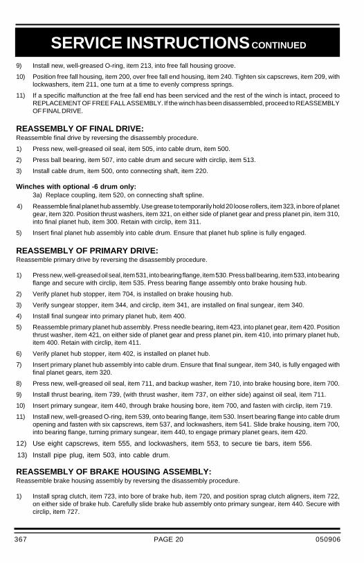
9) Install new, well-greased O-ring, item 213, into free fall housing groove.
10) Position free fall housing, item 200, over free fall end housing, item 240. Tighten six capscrews, item 209, withlockwashers, item 211, one turn at a time to evenly compress springs.
11) If a specific malfunction at the free fall end has been serviced and the rest of the winch is intact, proceed toREPLACEMENT OF FREE FALL ASSEMBLY. If the winch has been disassembled, proceed to REASSEMBLYOF FINAL DRIVE.
REASSEMBLY OF FINAL DRIVE:Reassemble final drive by reversing the disassembly procedure.
1) Press new, well-greased oil seal, item 505, into cable drum, item 500.
2) Press ball bearing, item 507, into cable drum and secure with circlip, item 513.
3) Install cable drum, item 500, onto connecting shaft, item 220.
Winches with optional -6 drum only:3a) Replace coupling, item 520, on connecting shaft spline.
4) Reassemble final planet hub assembly. Use grease to temporarily hold 20 loose rollers, item 323, in bore of planetgear, item 320. Position thrust washers, item 321, on either side of planet gear and press planet pin, item 310,into final planet hub, item 300. Retain with circlip, item 311.
5) Insert final planet hub assembly into cable drum. Ensure that planet hub spline is fully engaged.
REASSEMBLY OF PRIMARY DRIVE:Reassemble primary drive by reversing the disassembly procedure.
1) Press new, well-greased oil seal, item 531, into bearing flange, item 530. Press ball bearing, item 533, into bearingflange and secure with circlip, item 535. Press bearing flange assembly onto brake housing hub.
2) Verify planet hub stopper, item 704, is installed on brake housing hub.
3) Verify sungear stopper, item 344, and circlip, item 341, are installed on final sungear, item 340.
4) Install final sungear into primary planet hub, item 400.
5) Reassemble primary planet hub assembly. Press needle bearing, item 423, into planet gear, item 420. Positionthrust washer, item 421, on either side of planet gear and press planet pin, item 410, into primary planet hub,item 400. Retain with circlip, item 411.
6) Verify planet hub stopper, item 402, is installed on planet hub.
7) Insert primary planet hub assembly into cable drum. Ensure that final sungear, item 340, is fully engaged withfinal planet gears, item 320.
8) Press new, well-greased oil seal, item 711, and backup washer, item 710, into brake housing bore, item 700.
9) Install thrust bearing, item 739, (with thrust washer, item 737, on either side) against oil seal, item 711.
10) Insert primary sungear, item 440, through brake housing bore, item 700, and fasten with circlip, item 719.
11) Install new, well-greased O-ring, item 539, onto bearing flange, item 530. Insert bearing flange into cable drumopening and fasten with six capscrews, item 537, and lockwashers, item 541. Slide brake housing, item 700,into bearing flange, turning primary sungear, item 440, to engage primary planet gears, item 420.
12) Use eight capscrews, item 555, and lockwashers, item 553, to secure tie bars, item 556.
13) Install pipe plug, item 503, into cable drum.
REASSEMBLY OF BRAKE HOUSING ASSEMBLY:Reassemble brake housing assembly by reversing the disassembly procedure.
1) Install sprag clutch, item 723, into bore of brake hub, item 720, and position sprag clutch aligners, item 722,on either side of brake hub. Carefully slide brake hub assembly onto primary sungear, item 440. Secure withcirclip, item 727.
367 050906

PAGE 21
SERVICE INSTRUCTIONS CONTINUED
INCORRECT ASSEMBLY OF THE FRICTION PLATE AND DIVIDER PLATE STACK WILLREDUCE BRAKING CAPACITY AND ALLOW THE LOAD TO DROP, CAUSING PROPERTY
DAMAGE, SEVERE INJURY OR DEATH. REASSEMBLE PER INSTRUCTIONS.
DANGER
IMPORTANT: For proper brake function, verify that brake hub rotation is correct. When viewed fromthe motor end, the primary sungear of a counterclockwise hoisting winch must turnfreely clockwise and lock in the counterclockwise direction.
2) Install brake spacer, item 712, into brake housing, item 700.
NOTE: For PL5 free fall with -213 motor: Refer to 3a)
3) Starting and finishing with a divider plate, alternately install six divider plates, item 713, and five frictionplates, item 716.
3a) Starting with two divider plates, item 713, two friction plates, item 716, repeat two divider plates, twofriction plates, one divider plate, one friction plate ending with one divider plate, item 713.
4) Install new, well-greased O-rings, items 751 and 753, into piston, item 750. Carefully install brakepiston in brake housing, item 700.
5) Install ten brake springs, item 752.
REASSEMBLY OF HYDRAULIC MOTOR:If the hydraulic motor was disassembled, the following procedure should be followed for reassembly:
1) Clean all parts thoroughly before reassembly and apply grease liberally to all seals. Use only newseals (seal kit Part No. 24227) for hydraulic motor.
2) Install new, well-greased rubber channel seal, item 887 and item 888 into thrust block, item 885,so that protrusions in seal match recesses in block. Install new backup seal, item 897, over top ofchannel seal, leaving flat side of backup seal flush with surface of thrust block. Insert thrust block,item 885, into the gear housing, making sure seals are facing away from gear set.
3) Install well-greased section seal, item 869, on gear housing, item 860. Install gear housing togetherwith sealsection, onto motor adaptor, item 900, lined up on two dowel pins. Tap on tight using a soft headedhammer.
4) Install gear set, item 881 and item 882 in gear housing. (External spline end of gear goes into boreof motor adaptor.)
5) Insert other thrust block, complete with backup and channel seals, making sure seals are facing awayfrom gear set. Install a well-greased seal section, item 869, on gear housing.
6) Install port end cover, item 870, onto gear housing and lightly torque four hex capscrews, item 951,and lockwashers, item 953, to approximately 10 ft-lb (14 Nm).
REPLACE HYDRAULIC MOTOR ASSEMBLY:
1) Install new O-ring, item 707, onto motor adaptor pilot. Use grease to temporarily hold two O-rings,item 801, into recesses on flange of motor adaptor, item 900.
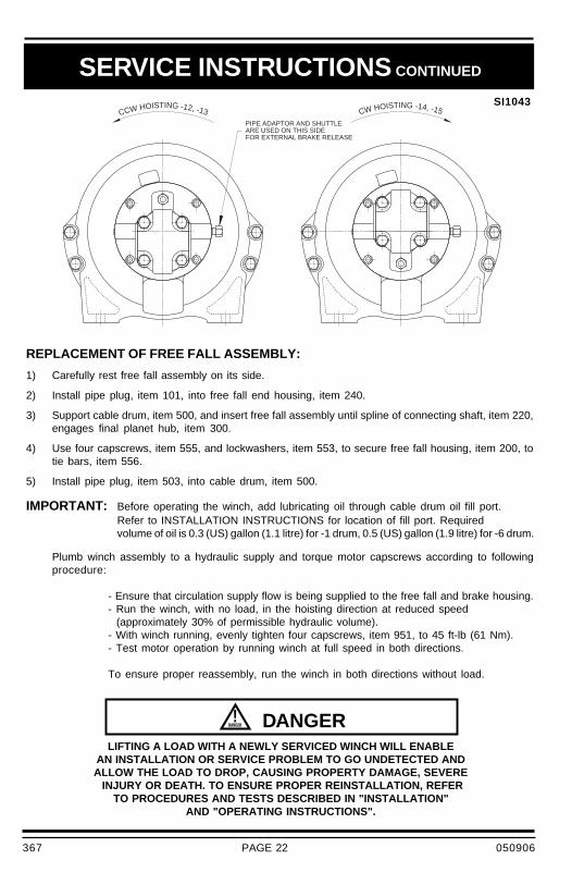
2) Position motor assembly with brake release pressure transfer holes of motor adaptor and brakehousing aligned, as per drawing # SI1043 on page 22. Tighten four capscrews, item 931, andlockwashers, item 933, one turn at a time to evenly compress springs.
367 050906
PAGE 22
FOR EXTERNAL BRAKE RELEASEARE USED ON THIS SIDE PIPE ADAPTOR AND SHUTTLE
CW HOISTING -14, -15CCW HOISTING -12, -13
SERVICE INSTRUCTIONS CONTINUED
SI1043
LIFTING A LOAD WITH A NEWLY SERVICED WINCH WILL ENABLEAN INSTALLATION OR SERVICE PROBLEM TO GO UNDETECTED ANDALLOW THE LOAD TO DROP, CAUSING PROPERTY DAMAGE, SEVERE INJURY OR DEATH. TO ENSURE PROPER REINSTALLATION, REFER
TO PROCEDURES AND TESTS DESCRIBED IN "INSTALLATION"AND "OPERATING INSTRUCTIONS".
DANGER
REPLACEMENT OF FREE FALL ASSEMBLY:
1) Carefully rest free fall assembly on its side.
2) Install pipe plug, item 101, into free fall end housing, item 240.
3) Support cable drum, item 500, and insert free fall assembly until spline of connecting shaft, item 220,engages final planet hub, item 300.
4) Use four capscrews, item 555, and lockwashers, item 553, to secure free fall housing, item 200, totie bars, item 556.
5) Install pipe plug, item 503, into cable drum, item 500.
IMPORTANT: Before operating the winch, add lubricating oil through cable drum oil fill port.Refer to INSTALLATION INSTRUCTIONS for location of fill port. Requiredvolume of oil is 0.3 (US) gallon (1.1 litre) for -1 drum, 0.5 (US) gallon (1.9 litre) for -6 drum.
Plumb winch assembly to a hydraulic supply and torque motor capscrews according to followingprocedure:
- Ensure that circulation supply flow is being supplied to the free fall and brake housing.- Run the winch, with no load, in the hoisting direction at reduced speed (approximately 30% of permissible hydraulic volume).- With winch running, evenly tighten four capscrews, item 951, to 45 ft-lb (61 Nm).- Test motor operation by running winch at full speed in both directions.
To ensure proper reassembly, run the winch in both directions without load.
367 050906

PAGE 23
Winch gear train lubricating oil should be changed after the initial six months or 50 hours of operation,whichever comes first. Lubricating oil should then be changed every 12 months or 500 operating hours,whichever comes first.
Hydraulic system fluid should be changed at least once every 12 months.
For optimum performance over an extended period of time, the following preventive maintenance serviceshould be done every 12 months or 500 operating hours, whichever comes first:
1) Disconnect all hydraulic hoses and remove the winch from its mounting.
2) Disassemble the winch as per instructions.
3) Discard and replace all O-rings and oil seals.
4) Clean all parts and inspect for wear and damage as per instructions. Replace worn ordamaged parts as required.
5) Reassemble the winch as per instructions.
6) Follow INSTALLATION and OPERATING INSTRUCTIONS when returning winch to itsmounting.
When ordering parts for the PULLMASTER Model PL5 planetary winch with free fall, always quote thecomplete model and serial number of the unit.
MODEL # ________________________
SERIAL # ________________________
RECOMMENDED MAINTENANCE
PULLMASTER WINCH CORPORATION reserves the right to change specifications and the design ofPULLMASTER planetary winches at any time without prior notice and without incurring any obligations.
367 050906

PAGE 24
I1124
INSTALLATION DIMENSIONS
Thi
s is
for
mod
els
with
cou
nter
cloc
kwis
eho
istin
g. F
or m
odel
s w
ith c
lock
wis
e ho
istin
g,ad
d 1.
2 in
ch (
30 m
m).
J
[144.5]
5.69
FREEFALLCIRCULATIONSUPPLYPORT1/4-18NPT
FREEFALLCLUTCH
RELEASEPORT
1/8-27NPT
[154]
6.1
[241]
ø9.5
[124]
4.9
[25]
1.0
[46]
1.8
FREEFALLCIRCULATIONRETURNPORT
1/2-14NPTOTHERSIDE
I
[279]
ø11.0
[187]
ø7.4
[13]
.5
[284]
11.2
[180]
7.1
[318]
12.5
[254]
10.0
[57]
2.3
[200.03]
7.875
[63]
2.5
H
C
OPTIONALEXTERNAL
BRAKERELEASEPORT
1/8-27NPT
PRESSURIZEFOR
CLOCKWISE
ROTATION
PRESSURIZE
FORCOUNTER
CLOCKWISE
ROTATION
COUNTERCLOCKWISE
SAFETYVALVE
MOTORPORTS
1.1/16-12UN
SAEO-RING
BOSS
4MOUNTINGHOLES
.53DIA
(13.5)USE
1/2DIAMETERBOLTS
GRADE8ORBETTER
FILLANDDRAIN
PORT3/8-18NPT
FO
R S
AF
ET
Y:
A m
inim
um o
f 5
wra
ps o
f w
ire r
ope
mus
t be
mai
ntai
ned
at a
ll tim
es.
MO
TOR
DIS
PLA
CE
ME
NT
I (in
)I (
mm
)C
OD
EC
C /
RE
V
-210
335.
714
5
-211
275.
313
5
-212
235.
112
9
-213
144.
611
6
DR
UM
CO
DE
-16
.67
.00
01
7.3
in1
67
17
7.8
04
39
mm
-61
0.0
10
.43
52
0.7
in2
54
26
5.0
45
26
mm
CH
JU
NIT
S
367 051117
PAGE 25
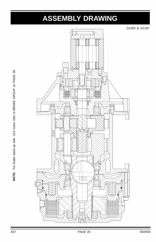
ASSEMBLY DRAWINGG1283 & G1197
NO
TE
: F
or b
rake
sta
ck-u
p w
ith -
213
mot
or r
efer
to
BR
AK
E G
RO
UP
on
PA
GE
28.
367 050906

PAGE 26
101 1 25032 PIPE PLUG 1/2" - 14 NPT115 1 26042 PLASTIC CAPLUG 1/2" -13NC THR'D171 1 25374 PLASTIC CAPLUG 1/8" NPT193 1 25395 PLASTIC CAPLUG 1/4" NPT200 1 23403 FREE FALL HOUSING202 1 22283 CLUTCH SPACER204 9 25953 DIVIDER PLATE206 8 26230 FRICTION PLATE208 1 25388 PLASTIC CAPLUG 1/2" NPT209 6 25949 CAPSCREW - SOCKET HEAD 3/8" - 16NC X 3.5" GRADE 8213 1 25033 O-RING -271 9-1/4"ID 1/8"CS215 1 26039 BALL BEARING220 1 23226 CONNECTING SHAFT226 1 23339 CLUTCH HUB228 1 25555 CIRCLIP ROTOR CLIP SH-250230 1 23402 CLUTCH PISTON231 1 26518 O-RING -90DURO -371 8-1/2"ID 3/16"CS232 22 22751 BRAKE SPRING233 1 26519 O-RING -90DURO -374 9-1/4"ID 3/16"CS240 1 23401 FREE FALL END HOUSING300 1 20367 FINAL PLANET HUB310 3 20369 FINAL PLANET PIN311 6 25091 CIRCLIP ROTOR CLIP SH-87320 3 20370 FINAL PLANET GEAR321 6 25068 THRUST WASHER TORRINGTON # TRA 1423323 60 25270 LOOSE ROLLER 5/32" X 1.25" TOR. # E151-Q340 1 20366 FINAL SUNGEAR341 1 25273 CIRCLIP ANDERTON # A1000-137344 1 20082 SUNGEAR STOPPER400 1 * PRIMARY PLANET HUB402 1 20372 PLANET HUB STOPPER410 3 * PRIMARY PLANET PIN411 6 25119 CIRCLIP ROTOR CLIP SH-62420 3 * PRIMARY PLANET GEAR421 6 25064 THRUST WASHER TORRINGTON # TRA 1018423 3 25063 NEEDLE BEARING TORRINGTON # B1012500 1 * CABLE DRUM502 1 20085 CABLE ANCHOR503 2 25085 PIPE PLUG 3/8" - 18 NPT505 2 25008 OIL SEAL507 2 25007 BALL BEARING # 6014511 1 * SET SCREW 5/16" - 18NC X 7/16"513 2 25006 CIRCLIP ROTOR CLIP HO-433520 1 * COUPLING530 1 20363 BEARING FLANGE531 1 25008 OIL SEAL533 1 25007 BALL BEARING # 6014535 1 25006 CIRCLIP ROTOR CLIP HO-433537 6 25171 CAPSCREW - HEX HEAD 5/16" - 18NC X 7/8" GRADE 5539 1 25276 O-RING -164 6-1/4" ID 3/32" CS541 6 25025 LOCKWASHER 5/16"553 8 25328 LOCKWASHER 7/16"555 8 25265 CAPSCREW - HEX HEAD 7/16" - 14NC X 1.25" GRADE 5556 2 * TIE BAR
* These parts vary. Refer to APPENDIX B.
PART NO. DESCRIPTION
PARTS REFERENCE - DRUM GROUP
QTY.ITEM NO.
367 050906
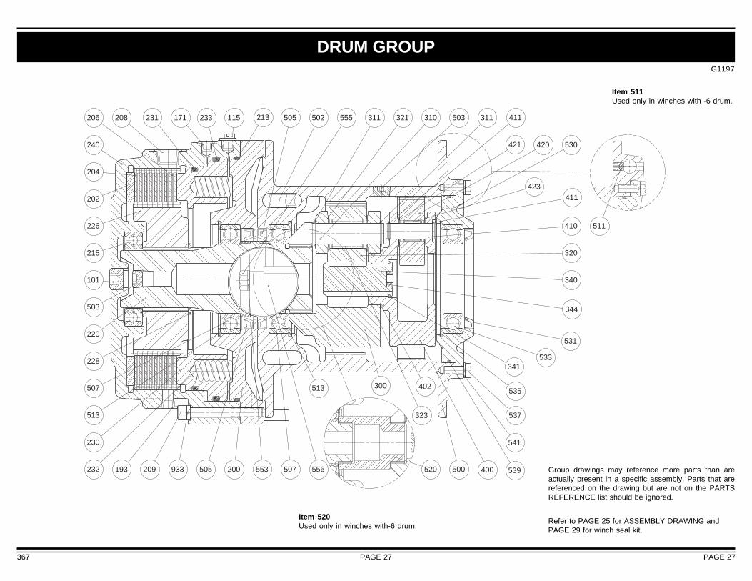
G1197
DRUM GROUP
Item 511Used only in winches with -6 drum.
367
Group drawings may reference more parts than areactually present in a specific assembly. Parts that arereferenced on the drawing but are not on the PARTSREFERENCE list should be ignored.
Refer to PAGE 25 for ASSEMBLY DRAWING andPAGE 29 for winch seal kit.
Item 520Used only in winches with-6 drum.
411423
421
411213233
505 520
511
500
555
340
400556553
300
115
420
171208
193
410
541
537
535
533
531
341
344
530
503 311321 310311502231 505206
240
204
202
226
215
101
503
220
228
507
513
230
232 209 933 200 507
513
323
320
402
539
PAGE 27 PAGE 27

G1283
Group drawings may reference more parts than areactually present in a specific assembly. Parts that arereferenced on the drawing but are not on the PARTSREFERENCE list should be ignored.Refer to PAGE 25 for ASSEMBLY DRAWING and PAGE 29 for winch seal kit.
BRAKE GROUP
050906367
897
871
872
888887869860 885881832
900 840
865 882
FOR PL5 WITH -213 MOTORFRICTION PLATE STACK-UP
809807802
805
950
951953
801707753754751
723
722
727
931
700 750713
716
712
720
719
737
440
704
710
711
739
752
PAGE 28

PAGE 29367 050906
440 1 ** SUNGEAR700 1 23033 BRAKE HOUSING704 1 20372 PLANET HUB STOPPER707 1 25015 O-RING -047 4-1/2"ID 1/16"CS710 1 20714 BACK UP WASHER FOR OIL SEAL #25278711 1 25278 OIL SEAL712 1 21902 BRAKE SPACER713 6 25024 DIVIDER PLATE716 5 20034 FRICTION PLATE (OPTIONAL - METALLIC PLATES # 26362)719 1 25539 CIRCLIP ROTOR CLIP SE-118720 1 22881 BRAKE HUB722 2 20183 SPRAG CLUTCH ALIGNER723 1 25187 SPRAG CLUTCH727 1 25492 CIRCLIP ROTOR CLIP SH-106737 2 25483 THRUST WASHER INA # AS 3047739 1 25537 THRUST BEARING INA # AXK 3047750 1 23034 PISTON751 1 25528 O-RING -90 DURO -245 4-3/8" ID 1/8"CS752 10 20340 BRAKE SPRING753 1 25261 O-RING -90 DURO -246 4-1/2" ID 1/8"CS754 1 23044 ORIFICE PLUG759 1 * STEEL BALL 5/32" DIA801 2 25792 O-RING -009 7/32" ID 1/16"CS802 1 * SHUTTLE805 2 25040 PIPE PLUG 1/8" - 27 NPT807 1 * *832 2 26785 CHECK VALVE840 1 20870 SAFETY VALVE860 1 ** GEAR HOUSING865 2 26371 DOWEL PIN869 2 26373 SECTION SEAL871 1 26378 PORT END COVER872 1 26379 PLUG - ORB #4881 1 ** GEAR DRIVEN882 1 ** GEAR DRIVE885 4 26788 THRUST BLOCK887 4 26789 CHANNEL SEAL888 4 26790 CHANNEL SEAL897 2 26786 BACKUP SEAL900 1 24154 MOTOR ADAPTOR931 4 25772 CAPSCREW933 4 25298 LOCKWASHER 3/8" HIGH COLLAR950 1 * MOTOR951 4 ** CAPSCREW - HEX HEAD953 4 26369 WASHER955 2 25536 PLASTIC CAPLUG 1.0625" -12 THREADED
23418 WINCH SEAL KIT, CONTAINS ITEMS:213, 231, 233, 505, 539, 707, 710, 711, 751, 753 AND 801.
24227 MOTOR SEAL KIT, CONSISTING OF ITEMS: 869, 887, 888 AND 897.
ITEM 950, MOTOR SUB-ASSY, CONSISTS OF ITEMS: 800, 802, 805, 807, 809,832, 860, 865, 869, 871, 872, 881, 882, 885, 887, 888, 897, 951 AND 953.
* These parts vary. Refer to BRAKE CODE CHART below.
** Refer to APPENDIX B.
ITEM NO.
PARTS REFERENCE - BRAKE GROUPPART NO.QTY. DESCRIPTION
BRAKE CODE CHART
802 SHUTTLE N/A 20849 20849 N/A
807 PIPE PLUG 1/8 - 27 NPT 25040 N/A N/A 25040
807 PIPE ADAPTOR 1/8 - 27 NPT N/A 25622 25622 N/A
809 CAPLUG 1/8 NPT N/A 25374 25374 N/A
950 MOTOR -210 24146 24210 24210 24146
950 MOTOR -211 24147 24211 24211 24147
950 MOTOR -212 24148 24212 24212 24148
950 MOTOR -213 24149 24213 24213 24149
BRAKE CODE
ITEM-12
PART NUMBERSPART DESCRIPTION
-13 -14 -15

PAGE 30 050906367
APPENDIX A
PL5-XX-210-1D 24 (US) gpm 2100 psi 17,578 lb-in 66 4500 lb 135 fpm 3328 lb 183 fpm91 l/min 145 bar 1986 Nm 20.0 kN 41 m/min 14.8 kN 56 m/min
PL5-XX-211-1D 11 (US) gpm 2250 psi 15,625 lb-in 35 4000 lb 72 fpm 3098 lb 92 fpm42 l/min 155 bar 1765 Nm 17.8 kN 22 m/min 13.8 kN 28 m/min
PL5A-XX-212-1D 11 (US) gpm 2400 psi 19,532 lb-in 29.5 5000 lb 60 fpm 3698 lb 82 fpm42 l/min 165 bar 2207 Nm 22.2 kN 18 m/min 16.4 kN 25 m/min
PL5-XX-213-1D 11 (US) gpm 2250 psi 7,813 lb-in 69 2000 lb 141 fpm 1479 lb 191 fpm42 l/min 155 bar 883 Nm 8.9 kN 43 m/min 6.6 kN 58 m/min
Performance specifications are based on 7/16 inch diameter wire rope.
Performance data (line pull and line speed) for models with -6 drum is same as equivalent model with-1 drum.
PERFORMANCE DATA
CABLE STORAGE
Model Number Hydraulic Requirement DrumTorque
DrumRPM
Bare Drum Full Drum
Flow Pressure Line Pull Line Speed Line Pull Line Speed
-6 7.38" 11.00" 10.00" 531 ft 333 ft 239 ft 168 ft 153 ft187 mm 279 mm 254 mm 162 m 101 m 73 m 51 m 47 m
CABLESTORAGE
BARRELDIAMETER
FLANGEDIAMETER
LENGTH WIRE ROPE DIAMETER1/4" 5/16" 3/8" 7/16" 1/2"

PAGE 31367 050906
APPENDIX B
400
ITEM NUMBERS
PART DESCRIPTION
DRUMCODE
DRUMCODE
'A' REDUCTION RATIOPART NUMBERS
STANDARD REDUCTION RATIOPART NUMBERS
PLANET PLANET PLANET SUNGEAR CABLE SET COUPLING TIE BARHUB PIN GEAR DRUM SCREW
-1 23022 20776 23023 23028 20361 - - 23042
-6 23022 20776 23023 23028 22123 25526 21745 23076
-1 20373 20080 20371 23078 20361 - - 23042
-6 20373 20080 20371 23078 22123 25526 21745 23076
410 420 440 500 511 520 556
MOTORCODE
860 881 882 951
ITEM
MOTOR PARTS
-210 26793 26791 26792 26370
-211 26797 26795 26796 26794
-212 26798 26799 26800 26801
-213 26802 26803 26804 26399
GEAR GEAR GEAR CAPSCREWHOUSING DRIVEN DRIVE HEX HEAD

PAGE 32 050906367
1/4 9 12
5/16 18 24
3/8 32 43
7/16 50 68
1/2 75 102
9/16 110 149
5/8 150 203
3/4 265 359
7/8 420 569
1 640 868
1 1/8 800 1085
1 1/4 1000 1356
NOTE: Unless otherwise specified, torque bolts per above chart.
TORQUENm
TORQUElb-ft
BOLT TORQUE CHART
BOLT DIAMETERInches
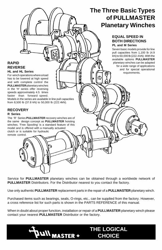
Service for PULLMASTER planetary winches can be obtained through a worldwide network ofPULLMASTER Distributors. For the Distributor nearest to you contact the factory.
Use only authentic PULLMASTER replacement parts in the repair of a PULLMASTER planetary winch.
Purchased items such as bearings, seals, O-rings, etc., can be supplied from the factory. However,a cross reference list for such parts is shown in the PARTS REFERENCE of this manual.
When in doubt about proper function, installation or repair of a PULLMASTER planetary winch pleasecontact your nearest PULLMASTER Distributor or the factory.
The 'R' Series PULLMASTER recovery winches are ofthe same design concept as PULLMASTER hoistingwinches. 'Free Spooling' is a standard feature of thismodel and is offered with a manually actuatedclutch or is suitable for hydraulicremote control.
RECOVERYR Series
PML THE LOGICALCHOICE
For winch operations where a loadhas to be lowered at high speedand with complete control thePULLMASTER planetary winchesin the 'H' series offer reversingspeeds approximately 4.5 timesfaster than forward speed.Models in the series are available in line pull capacitiesfrom 8,500 lb (37.8 kN) to 50,000 lb (222.4kN).
RAPIDREVERSEHL and HL Series
The Three Basic Typesof PULLMASTER
Planetary Winches
Seven basic models provide for linepull capacities from 1,100 lb (4.9kN) to 50,000 lb (222.4 kN). With theavailable options PULLMASTERplanetary winches can be adapted
for a wide range of applicationsand for special operational
requirements.
EQUAL SPEED INBOTH DIRECTIONSPL and M Series