Planetary Gearboxes GTS for Mounting to AC Motors - BEC Rexroth/Accessories/Gear/GTS... ·...
68
Planetary Gearboxes GTS for Mounting to AC Motors Project Planning Manual DOK-GEAR**-GTS********-PR06-EN-P mannesmann Rexroth engineering Indramat Rexroth 7=78)1
Transcript of Planetary Gearboxes GTS for Mounting to AC Motors - BEC Rexroth/Accessories/Gear/GTS... ·...
Planetary Gearboxes GTSfor Mounting to AC Motors
Project Planning Manual
DOK-GEAR**-GTS********-PR06-EN-P
mannesmannRexroth
engineering
IndramatRexroth
7=78)1���

About this Documentation Projekt Planning Manual
DOK-GEAR**-GTS********-PR06-EN-P
Planetary Gearboxes GTS
for Mounting to AC Motors
Project Planning Manual
DOK-GEAR**-GTS********-PR06-EN-P
• Document Number: 120-1200-B301-06/EN
This documentation assists
• in the selection of a GTS planetary gear box
• in the clarification of technical data
• in the mechanical integration of the gearbox into the maschine
• when organizing order information
Description ReleaseDate
Notes
209-0069-4389-00 1995 1st edition
209-0069-4389-01 02.96 MKD motors added
DOK-GEAR**-GTS********-PRJ2-EN-P 06.97 MHD motors added
DOK-GEAR**-GTS********-PRJ3-EN-P 08.98 Availability changes
DOK-GEAR**-GTS********-PR04-EN-P 01.99 New: S1 mode
DOK-GEAR**-GTS********-PR05-EN-P 03.99 Revision
DOK-GEAR**-GTS********-PR06-EN-P 12.99 Revision
1999 Rexroth Indramat GmbH
Copying this document, giving it to others and the use or communicationof the contents thereof without express authority, are forbidden. Offendersare liable for the payment of damages. All rights are reserved in the eventof the grant of a patent or the registration of a utility model or design (DIN34-1).
All rights are reserved with respect to the content of this documentationand the availability of the product.
Rexroth Indramat GmbHBgm.-Dr.-Nebel-Str. 2 • D-97816 Lohr a. Main
Telephone 09352/40-0 • Tx 689421 • Fax 09352/40-4885
http://www.rexroth.com/indramat
Dept. ECM3, ECM5 (WS,SK)
This document has been printed on chlorine-free bleached paper..
Title
Type of Documentation
Document Typecode
Internal File Reference
Purpose of Documentation
Record of Revisions
Copyright
Validity
Published by
Note

Projekt Planning Manual Contents I
DOK-GEAR**-GTS********-PR06-EN-P
Contents
1 Product Introduction 1-1
2 Dimensioning and Selecting 2-1
2.1 Dimensioning ................................................................................................................................. 2-1
2.2 The Selection Process ................................................................................................................... 2-4
3 Technical Data 3-1
3.1 Ambient Conditions ........................................................................................................................ 3-1
3.2 Mechanical Features...................................................................................................................... 3-5
3.3 Possible Combinations of GTS Planetary Gearboxes with AC Motors ......................................... 3-8
4 Planetary Gearbox GTS 060 4-1
4.1 Technical Data ............................................................................................................................... 4-1
4.2 Allowed Shaft Loads ...................................................................................................................... 4-2
4.3 Sizes............................................................................................................................................... 4-3
4.4 Available versions .......................................................................................................................... 4-4
5 Planetary Gearbox GTS 075 5-1
5.1 Technical Data ............................................................................................................................... 5-1
5.2 Allowed Shaft Loads ...................................................................................................................... 5-4
5.3 Sizes............................................................................................................................................... 5-5
5.4 Available versions .......................................................................................................................... 5-6
6 Planetary Gearbox GTS 100 6-1
6.1 Technical Data ............................................................................................................................... 6-1
6.2 Allowed Shaft Loads ...................................................................................................................... 6-4
6.3 Sizes............................................................................................................................................... 6-5
6.4 Available versions .......................................................................................................................... 6-6
7 Planetary Gearbox GTS 140 7-1
7.1 Technical Data ............................................................................................................................... 7-1
7.2 Allowed Shaft Loads ...................................................................................................................... 7-4
7.3 Sizes............................................................................................................................................... 7-5
7.4 Available Versions.......................................................................................................................... 7-6
8 Planetary Gearbox GTS 180 8-1
8.1 Technical Data ............................................................................................................................... 8-1
8.2 Allowed Shaft Loads ...................................................................................................................... 8-4

II Contents Projekt Planning Manual
DOK-GEAR**-GTS********-PR06-EN-P
8.3 Sizes............................................................................................................................................... 8-5
8.4 Available versions .......................................................................................................................... 8-6
9 Planetary Gearbox GTS 210 9-1
9.1 Technical Data ............................................................................................................................... 9-1
9.2 Allowed Shaft Loads ...................................................................................................................... 9-3
9.3 Sizes............................................................................................................................................... 9-4
9.4 Available versions .......................................................................................................................... 9-5
10 Planetary Gearbox GTS 240 10-2
10.1 Technical Data ............................................................................................................................. 10-2
10.2 Allowed Shaft Loads .................................................................................................................... 10-3
10.3 Sizes............................................................................................................................................. 10-4
10.4 Available versions ........................................................................................................................ 10-5
11 Order Designations 11-1
12 Service Notes 12-1
12.1 Contacting Customer Service ...................................................................................................... 12-1
12.2 Faulty Report................................................................................................................................ 12-2
13 Index 13-1
14 Kundenbetreuungsstellen - Sales & Service Facilities 14-1

Projekt Planning Manual Product Introduction 1-1
DOK-GEAR**-GTS********-PR06-EN-P
1 Product IntroductionPlanetary gearboxes of the GTS series for mounting to AC motors whenused in conjunction with the relevant Rexroth Indramat drive controllerscreate automation systems that can be used over a wide range ofindustries.
They are especially suited for S5 type operations used in gear racks ortoothed belt drives in handling systems that are characterized by highvelocity and accelerations (e.g., loaders and robots).
They are also suited for S1 type operations generally found in printingmachine industries.
GT
S24
0
GT
S21
0
GT
S18
0
GT
S14
0
GT
S10
0
GT
S07
5
GT
S06
0
4
5
7
10
20
50
0
500
1000
1500
2000
2500
3000
3500
max
. gea
rbox
out
put t
orqu
e
Size
Ratio
DGGTS
Fig. 1-1: GTS planetary gearbox torque
GTS planetary gearboxes offer coaxial inputs and outputs. A couplingcomponent connects the output shaft of the AC servo motor to the sunwheel of the planetary gearbox. This sun wheel propels three planetpinions which unroll on a hollow shaft wheel. The planet pinions are setinto a pinion cage which functions as an output. A balanced load sharingis created by distributing the mesh of the teeth over the three planetpinions, making the construction compact as well.
• Maintenance-free operation due to the use of service-life lubrication(see Planetary Gearbox GTS Service Guidelines).
• Can be used unter adverse environmental conditions because of itscompletely closed housing which has a protection category of IP 65.
Applications
Gradations
Functional principle
Operating reliability

1-2 Product Introduction Projekt Planning Manual
DOK-GEAR**-GTS********-PR06-EN-P
• A gear-tooth system with low backlash due to gear wheel pairs.
• High torsional strength because the load is distributed over threeplanet pinions.
• High degree of efficiency due to the planet pinion principle.
• High dynamics due to favorable torque/inertia ratio.
• Compact construction means light weight.
• Pinions and belt pulleys can be directly mounted onto the shaftbecause the bearing assemlby design makes high radial loadspossible.
• The flange design permits drill holes in the flange as per B5 (DIN42959 Sec. 1, ed. 08.77) with dril holes in flange.
• The output elements can be mounted in two different ways:- force-locked shaft-hub connection with a plain output shaft- form-fitting shaft-hub connection with output shaft with keyway.
High level performance
Easy mounting to the machine

Projekt Planning Manual Dimensioning and Selecting 2-1
DOK-GEAR**-GTS********-PR06-EN-P
2 Dimensioning and Selecting
2.1 Dimensioning
Applications in which GTS planetary gearboxes are advantageously usedcan be broken down into the following typical velocity-time diagrams:
• triangular velocity variation with dead time
• operation with constant velocity and dead time
• operation with trapezoidal velocity variation and dead time
• operation at constant velocity without deadtime (S1)
These characteristic velocity-time diagrams primarily determine thelayout.
Triangular Operation with Dead TimeThis operating mode is typical of all feed movements with high dynamicssuch as is generally found in drum feed mechanisms of the tin, paper,synthetics or packaging industries.
DGdrei
time
velocity v
Fig. 2-1 Velocity/time diagram for triangular operations
This operating mode design is primarily dictated by the required maximumM
max and effective torques M
eff.

2-2 Dimensioning and Selecting Projekt Planning Manual
DOK-GEAR**-GTS********-PR06-EN-P
Constant Velocity with Dead TimeThis mode is typical of all feed movements as commonly seen in windingunits, roller drives and dosage devices in machines used in the tin, paper,synthetics or packaging industries.
DGkons
time
velocity vor speed n
Fig. 2-2: Velocity/time diagram for operation at constant velocity
This design is primarily dictated by the required continuous torque MdNand the mean velocity vmittel or mean speed nmittel.
Trapezoidal Operations with Dead Time
This mode is typical for most feed movements. It is common in loadersand handling systems in all types of industries.
DGtrap
time t
velocity vor speed n
Fig. 2-3: Velocity/time diagram for trapezoidal modes
The criteria for this mode are primarily determined by the maximumtorque Mmax in acceleration phases, the rms torque Meff over the entire
cycle time and the mean velocity vmittel.

Projekt Planning Manual Dimensioning and Selecting 2-3
DOK-GEAR**-GTS********-PR06-EN-P
Constant Velocity without Dead Time (S1)
This is characteristic of printing machine drives.
DGkonsGeschw.fh7
time t
velocity vor speed n
Fig. 2-4: Velocity/time diagram for constant velocity
This layout is determined by the required continuous torque MdN and thevelocity v or speed n.

2-4 Dimensioning and Selecting Projekt Planning Manual
DOK-GEAR**-GTS********-PR06-EN-P
2.2 The Selection Process
Drive-determining VariablesSelecting the drive, i.e., the most suitable motor/gearbox combinationoperated by a drive controller, means determining the relevant variablessuch as
• frictional torque
• weight torque
• processing torque
• acceleration torque
• rms torque
• required speed
• ON time
Layout CriteriaThe motor/gearbox combination operated by a drive controller must beable to meet the following demands:
• it must achieve the required speed
• the continuous torque must be greater than the rms torque
• the short-term operating torque must be greater than the sum offrictional, weight and finishing torques
• maximum torque must be greater than the sum of frictional, weightand acceleration torques
• the required ramp-up time must remain within the limits of the relevantdrive
• the ON time of the GTS must be less than 60% of the technical dataspecified for S5 intermittent operation mode
Note: Also, note the following about the gearbox
• the maximum motor torque must be smaller than the maximum gearinput torque
• and the maximum motor speed must be smaller than maximumallowable gear input speed.

Projekt Planning Manual Technical Data 3-1
DOK-GEAR**-GTS********-PR06-EN-P
3 Technical Data
3.1 Ambient Conditions
Maximum Ambient Temperature and Installation Elevation
The performance data specified is achieved under the followingconditions:
Ambient temperature: 0 to +45°
Elevation: 0 to 1000 meters above sea level
Power ratings drop, as can be seen below, under other than thoseconditions. If the ambient temperature is not maintained and installationelevations are higher, then it is necessary to multiply the power ratings bythe two factors.
DGTemp
Load at higherambient temperatures
than 45 °C
Load at installationelevations higher
than 1000 m
load
fact
or f T
load
fact
or f H
ambient temp. in °C install. elev. above sea level1000 2000 3000 4000 5000
0,6
0,8
1
0,6
0,8
1
40 45 50 55 0
Fig. 3-1: Load capacities with higher ambient temperatures and greaterinstallation elevations

3-2 Technical Data Projekt Planning Manual
DOK-GEAR**-GTS********-PR06-EN-P
Protection CategoryAs per DIN VDE 0470 Sec. 1 (ed. 11.92), the AC motor with mountedGTS gearbox is protected by the housing against
• contact with parts carrying voltage or moving parts
• penetration of foreign objects and water.
The protection categories are defined with IP (international protection)and two numbers. The code for AC motors with GTS are
• IP 65 for housing of motor and gearbox
• IP 64 for output shaft of the gearbox
• IP 65 for the power and feedback connections of the motor withcorrect mounting
The first number specifies the degree of protection against contact andpenetration of extrinsic objects. A 6 thus means
• protection against penetration by dust (dust proof)
• complete contact protection.
The second number describes the protection against water. A 5 thusmeans
• protection against a jet of water emitting from a nozzle from alldirections against the machine (housing),
and a 4 means
• protection against water coming from all directions against thehousing.
Gearbox used in areas subject to explosion hazards
Rexroth Indramat assumes neither liability nor guarantee for gearboxesused in areas that are subject to explusion hazards. The manufacturer ofthe installation is responsible for the use in such areas.
The gearboxes supplied by Rexroth Indramat have not been tested tosatisfy standards in such areas. Gearboxes that can be used in areassubject to explosion hazards are not available from Rexroth Indramat.

Projekt Planning Manual Technical Data 3-3
DOK-GEAR**-GTS********-PR06-EN-P
Housing FinishThe finish is a basic prime coat. An additional coat is possible but may notexceed a max. 40 µm.
The coating is resistant to
• weathering, yellowing and chalking
• and against acids and caustic solutions.
Operating mode S1(Continous operation)
Planetary gearboxes GTS are suited as per DIN VDE 0530 for S1operation.

3-4 Technical Data Projekt Planning Manual
DOK-GEAR**-GTS********-PR06-EN-P
Operating mode S5(Intermittent mode)
Planetary gearboxes of the GTS type are suited as per DIN VDE 0530 foroperating mode S5 (intermittent mode with decel). ON time may notexceed 60%.
EDT T T
TA B Br
S
=+ +
≤• % %100 60
ED: ON tme in %TA: ramp up in sTB: processing time in sTBr: decel time in sTS: duty cycle in s
The number of cycles must not exceed 1,000 per hour. A cycle is definedas one traversing action consisting of one acceleration and onedeceleration procedure.
DGbetr
time
PV
n
TA TB TBr
Ts
n = speedPV = power lossTA = ramp up timeTB = processing timeTBr = decel timeTs = duty cycle time
chronological power losschronological speed
Fig. 3-2: Operating mode S5 (intermittent mode with electronic braking)
If more than 1,000 cycles per hour are needed, then the following deratingapplies to torque and power data.
DGSPProjLast
1,0
0,5
1000 2000 3000
number of cycles per 1/h
dera
ting
fact
or k
L
4000 5000 6000 7000 80000
Fig. 3-3: Derating with higher number of cycles
Derating with an increasednumber of cycles

Projekt Planning Manual Technical Data 3-5
DOK-GEAR**-GTS********-PR06-EN-P
3.2 Mechanical Features
Construction, Mounting Orientation
Indramat’s GTS gearboxes are built in B05 form for flange mounting. Asper DIN IEC 34-7 (ed. 12.92) the orientations as illustrated in Fig. 3-4 arepossible.
IM B5
IM V1 IM V3
Allowed mounting orientations as per DIN IEC 34-7
zulEinbau.fh7
Fig. 3-4: Permissible mounting orientations
Note: When mounting the gearbox in the IM V3 orientation itbecomes necessary to prevent liquids collecting at the outputshaft as otherwise these will possibly, over time, penetrate intothe machine.

3-6 Technical Data Projekt Planning Manual
DOK-GEAR**-GTS********-PR06-EN-P
Lubrication
The amount of oil needed to lubricate the gearbox depends upon themounting orientation. The amount of oil in the gearbox at delivery isadjusted to that orientation which was ordered. It is necessary, therefore,to specify an orientation.
The gearboxes for S5 operations are service-life lubricated with high-quality synthetic oils. Nonetheless, it is recommended to change the allabout every 10,000 operating hours (see document „Planetary gearboxesGTS Service Notes“).
The gearboxes for S1 mode are lubricated for life. Maintenance work isnot necessary.
Output ShaftThe output shaft of the planetary gearbox is available in the followingvariants:
• Plain shaft (standard) for
form-fitting shaft-hub connections.
This achieves excellent smooth running and a backlash-free connectionbetween shaft and hub.
Note: We recommend the use of output shafts with friction-lockedshaft-hub connections.
or
• Output shaft with keyway per DIN 6885, sh. 1, (ed. 08.68) for
form-fitting shaft-hub connections.
This type of connection is suited for less stringent demands and forabsorbing torque from a constant direction. It requires an additional axiallink for the hub. A center bore with winding is situated at the small end ofthe gearbox output shaft for this purpose.
Shaft LoadThe axial and radial shaft loads must be individually checked:
The radial shaft load depends on
• the point of application of force and
• mean speed
This data can be found in the diagrams in the "Technical Data”. Thenominal bearing service life equals about 30,000 operating hours (bearingcalculations based on DIN ISO 281, ed. 12.90).
The axial shaft load is listed in the ”Technical Data”.
Lubrication depends onmounting orientation
Oil changes

Projekt Planning Manual Technical Data 3-7
DOK-GEAR**-GTS********-PR06-EN-P
Mounting Output Components
The nut for the keyed end used for pre-stressing the gerbox outputbearing may not be used as a limit stop for the output components. Allaxial forces must be conducted directly over the output shaft into thegearbox.
MZanbau
Fig. 3-5: Mounting output components

3-8 Technical Data Projekt Planning Manual
DOK-GEAR**-GTS********-PR06-EN-P
3.3 Possible Combinations of GTS Planetary Gearboxes withAC Motors
The following table clearly identifies the best combinations of GTSplanetary gearbox and AC motors.
Planetary Motor type
gearbox MAC MKD MHD MDD MKE MHP 2AD ADP ADF
GTS060 2) MKD025 MKE035
MKD041 MHD041 MKE045 MHP041
GTS075 MKD041 MHD041 MKE045 MHP041
MAC063 MDD065
MAC071 MKD071 MHD071 MDD071 MHP071
GTS100 MKD041 MHD041 MKE045 MHP041
MAC063 MDD065
MAC071 MKD071 MHD071 MDD071 MHP071
MAC090 MKD090 MHD090 MDD090 MHP090
MAC093 MHD093 MDD093 MKE096 MHP093
GTS140 MAC071 MKD071 MHD071 MDD071 MHP071
MAC090 MKD090 MHD090 MDD090 MHP090
MAC093 MHD093 MDD093 MKE096 MHP093
MAC112 MKD112 MHD112 MDD112 MHP112
MAC115 MDD115 MKE116
GTS180 MAC090 MKD090 MHD090 MDD090 MHP090 2AD100 ADF100
MAC093 MHD093 MDD093 MKE096 MHP093 2AD101
MAC112 MKD112 MHD112 MDD112 MHP112 2AD104 ADP104 ADF104
MAC115 MHD1151) MDD115 MKE116 MHP1151)
GTS210 MAC093 MHD093 MDD093 MHP093 2AD100 ADF100
MAC112 MKD112 MHD112 MDD112 MHP112 2AD101
MAC115 MHD115 MDD115 MKE116 MHP115 2AD104 ADP104 ADF104
2AD132 ADP134 ADF132
2AD134 ADF134
GTS240 2) MAC115 MHD115 MDD115 MHP115 2AD100 ADF100
2AD101
2AD104 ADP104 ADF104
2AD132 ADF132
2AD134 ADP134 ADF134
2AD1601)
2AD1641) ADP164
1) Only single-stage gearboxes
2) Not for S1 continuous operation mode (C version).
Fig. 3-6: Possible gearbox/motor combinations with GTS gearboxes
Note: The AC servo motors must be equipped with a plain outputshaft for mounting the GTS planetary gearboxes.

Projekt Planning Manual Planetary Gearbox GTS 060 4-1
DOK-GEAR**-GTS********-PR06-EN-P
4 Planetary Gearbox GTS 060
4.1 Technical Data
Designation Symbol Unit GTS 060-MIV
single-stage two-stage
Ratio i - 4 5 7 10 20 50
max. input speed nin,max min-1 6000 6000 6000 6000 6000 6000
max.
input torque 1) Min,max Nm 10.3 8.2 5.9 3.3 2.1 0.8
max. output speed nout,max min-1 1500 1200 857 600 300 120
max. output torque 1) Mout,max Nm 40 40 40 32 40 40
max. output power Pout,max kW 6.28 5.03 3.59 2.01 1.26 0.50
nominal input speed nin,nominal min-1 3300 3300 4000 4000 4400 4800
nominal output torque Mout,nominal Nm 25 25 25 15 25 25
Inertia 2)
when mounted to motors:
025 / 035J kgcm2 0.12 0.12 0.11 0.10 0.13 0.10
Inertia 2)
when mounted to motors:
041 / 045J kgcm2 0.17 0.17 0.16 0.15 0.18 0.15
1) max. 1000 cycles/hoursour
2) moment of inertia of gearbox as relates to input side
Fig. 4-1: Ratio dependent data GTS 060
Designation Symbol Unit GTS 060
single-stage two-stage
Efficiency η % 97 94
Backlash 1) ∆ arcmin ≤ 6 (≤ 4)2) ≤ 8 (≤ 6)2)
Torsional stiffness 3) D Nm/rad 10300
Service life L10h h >30000
Lubricant - - synthetic oil with viscosity of VG 220
allowable ambienttemperature
TUm °C 0...45
Allowed gearboxhousing temperature inthe MIV version
TG °C -10...+90
Noise level Lp dB (A) ≤ 68 4)
Protection category - - IP 65 5)
Weight m kg 1.5 1.8
Mechanicallycombinable withmotor size
025 / 035 / 041 / 045
1) references gear output side at ±2% nominal output torque or gear and fixed gear input side
2) bracket values apply to limited gear backlash
3) Torsional stiffness of gear or gear output side with fixed gear output side
4) at gear input speed of 3000 min-1
5) output shaft leadthrough excepted which is IP 64
Fig. 4-2: General data GTS 060
Ratio dependent data (only forS5 intermittent operation mode
possible)
General data
4-2 Planetary Gearbox GTS 060 Projekt Planning Manual
DOK-GEAR**-GTS********-PR06-EN-P
4.2 Allowed Shaft Loads
500
750
1000
1250
1500
1750
2000
2250
2500
2750
3000
0 5 10 15 20 25 30x in mm
FR
in N1000
1100
1200
FA
in N
900
800
700
600
500
400
300
200
1,20
1,00
0,80
0,6010 20 30 40 50 60 70
r in mm
corr
. fac
tor
MZWell60
FA
FR
x
r
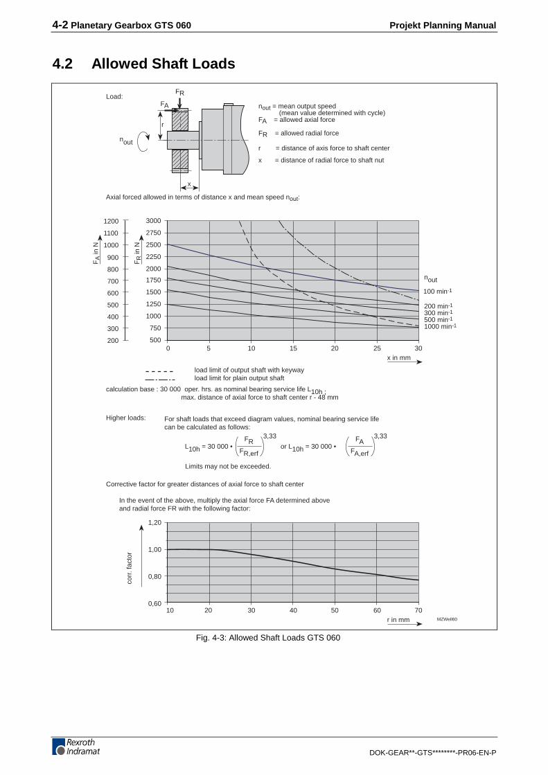
Load:nout = mean output speed (mean value determined with cycle)FA = allowed axial force
FR = allowed radial force
r = distance of axis force to shaft center
x = distance of radial force to shaft nut
Axial forced allowed in terms of distance x and mean speed nout:
FRFR,erf
3,33
100 min-1
200 min-1
300 min-1
500 min-1
1000 min-1
L10h = 30 000 •
nout
nout
FAFA,erf
3,33
or L10h = 30 000 •
calculation base : 30 000 oper. hrs. as nominal bearing service life L10h ; max. distance of axial force to shaft center r - 48 mm
load limit of output shaft with keywayload limit for plain output shaft
Corrective factor for greater distances of axial force to shaft center
In the event of the above, multiply the axial force FA determined above and radial force FR with the following factor:
For shaft loads that exceed diagram values, nominal bearing service lifecan be calculated as follows:
Limits may not be exceeded.
Higher loads:
Fig. 4-3: Allowed Shaft Loads GTS 060

Projekt Planning Manual Planetary Gearbox GTS 060 4-3
DOK-GEAR**-GTS********-PR06-EN-P
4.3 Sizes
ø 6
0 g6
ø 3
0
ø16
k6
025035041045
81818181
101101101101
62
5,5
"B"
6
28
2
20
center drill hole perDIN 332, shl. 2, form DRM5 - 12,5
Dim. "A"see size sheet
68Motor
MBGTS60
252 5 h9
18Ø
58,
5
type plate
1
Mounting opening to connect motor and gearbox.After mounting, these openings are closed with a plastic plug thatis flush with the housing.
Oil tapping screws 1 x DIN 906-M6
2
3
3
1
2
3
dim. "B"single
flanged motorsize
dim. "B"two• Concentricity of shaft end,
coaxility and excentricity of conn. flange as per DIN 42955, tolerance class R
• Option: output shaft with keyway
Fig. 4-4: Sizes GTS 060
4-4 Planetary Gearbox GTS 060 Projekt Planning Manual
DOK-GEAR**-GTS********-PR06-EN-P
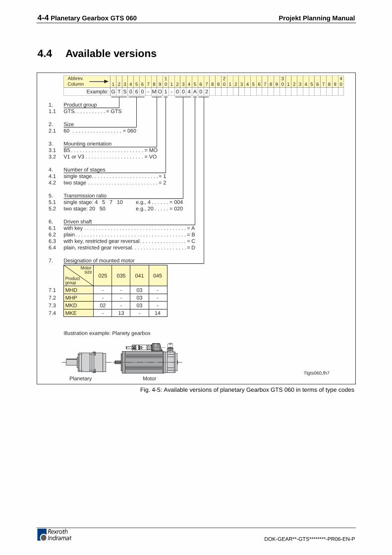
4.4 Available versions
1. Product group1.1 GTS. . . . . . . . . . . = GTS
2. Size2.1 60 . . . . . . . . . . . . . . . . . = 060
3. Mounting orientation3.1 B5 . . . . . . . . . . . . . . . . . . . . . . . . . = MO3.2 V1 or V3 . . . . . . . . . . . . . . . . . . . . = VO
4. Number of stages4.1 single stage. . . . . . . . . . . . . . . . . . . . . . .= 14.2 two stage . . . . . . . . . . . . . . . . . . . . . . . . = 2
5. Transmission ratio5.1 single stage: 4 5 7 10 e.g., 4 . . . . . . = 0045.2 two stage: 20 50 e.g., 20 . . . . . = 020
6. Driven shaft6.1 with key . . . . . . . . . . . . . . . . . . . . . . . . . . . . . . . . . . . = A6.2 plain . . . . . . . . . . . . . . . . . . . . . . . . . . . . . . . . . . . . . . = B6.3 with key, restricted gear reversal. . . . . . . . . . . . . . . . = C6.4 plain, restricted gear reversal. . . . . . . . . . . . . . . . . . . = D
7. Designation of mounted motorMotor
sizeProductgroup
025 035 041 045
7.1 MHD - - 03 -7.2 MHP - - 03 -7.3 MKD 02 - 03 -7.4 MKE - 13 - 14
Illustration example: Planety gearbox
1 2 3 4 6 7 8 9105 1 2 3 4 6 7 8 9
205 1 2 3 4 6 7 8 9
305 1 2 3 4 6 7 8 9
405
Example:
Abbrev.Column
G T S 0 6 0 - M O 1 - 0 0 4 A 0 2
Planetary MotorTlgts060.fh7
Fig. 4-5: Available versions of planetary Gearbox GTS 060 in terms of type codes

Projekt Planning Manual Planetary Gearbox GTS 075 5-1
DOK-GEAR**-GTS********-PR06-EN-P
5 Planetary Gearbox GTS 075
5.1 Technical Data
Designation Symbol Unit GTS 075-M/V
single-stage two-stage
Ratio i - 4 5 7 10 20 50
max. input speed nin,max min-1 6000 6000 6000 6000 6000 6000
max.
input torque 1) Min,max Nm 25.8 20.6 14.7 8.3 5.3 2.1
max. output speed nout,max min-1 1500 1200 857 600 300 120
max.
output torque 1) Mout,max Nm 100 100 100 80 100 100
max. output power Pout,max kW 15.7 12.5 9 5 3.1 1.26
nominal input speed nin,nom. min-1 2900 2900 3100 3100 3500 3800
nominal output torque Mout,nom. Nm 70 70 70 45 70 70
Inertia 2)
when mounted to motors:
041 / 045 / 063 / 065J kgcm2 0.57 0.49 0.43 0.40 0.52 0.39
Inertia 2)
when mounted to motors:
071J kgcm2 0.63 0.55 0.49 0.46 0.58 0.45
1) with max. 1000 cycles/hours
2) moment of inertia of gearbox as relates to input side
Fig. 5-1: Ratio dependent data GTS 075
Ratio dependent data for S5intermittent operation mode

5-2 Planetary Gearbox GTS 075 Projekt Planning Manual
DOK-GEAR**-GTS********-PR06-EN-P
Designation Symbol Unit GTS 075-C
single-stage two-stage
Ratio i - 3 4 5 7 10 20
nominal input speed nin,nom. min-1 4500 4500 4500 4500 4500 4500
Nominalinput torque Min,nom. Nm 8.2 9 7,6 5,6 2,5 2,0
nominal output speed nout,nom. min-1 1500 1125 900 642 450 225
nominaloutput torque Mout,nom. Nm 24 35 37 38 24 37
nominal output power Pout,nom. kW 3.8 4.1 3.5 2.5 1.1 0.9
max. input speed 1) nin,max min-1 6000 6000 6000 6000 6000 6000
max. input torque 1) Min,max Nm 13 14 12.2 8.7 3.9 3.1
Inertia 2) J kgcm2 0.82 0.63 0.55 0.49 0.46 0.58
1) for max. 1 s
2) moment of inertia of gearbox as relates to input side
Fig. 5-2: Ratio dependent data GTS 075
Designation Symbol Unit GTS 075
single-stage two-stage
Efficiency η % ≥ 97 ≥ 94
Backlash 1) ∆ arcmin ≤ 6 (≤ 4)2) ≤ 8 (≤ 6)2)
Torsional stiffness 3) D Nm/rad 27500
Service life L10h h >30000
Lubricant - - synthetic oil with viscosity of VG 220 or greases
allowable ambienttemperature
TUm °C 0...45
permissible gearhousing temperaturewith MIV-Versionwith S1 mode
TG °C
-10...+90-10...+110
Noise level Lp dB (A) ≤ 68 4)
Protection category - - IP 65 5)
Weight m kg 2.8 3.1
Mechanicallycombinable withmotor size
041 / 045 / 063 / 065 / 071/
1) references gear output side at ±2% nominal output torque or gear and fixed gear input side
2) bracket values apply to limited gear backlash, not available in C version (S1 mode)
3) Torsional stiffness of gear or gear output side with fixed gear output side
4) at gear input speed of 3000 min-1
5) output shaft leadthrough excepted which is IP 64.
Fig. 5-3: General data GTS 075
Ratio dependent data forContinous operation S1
General data

Projekt Planning Manual Planetary Gearbox GTS 075 5-3
DOK-GEAR**-GTS********-PR06-EN-P
5.2 Allowed Shaft Loads
0 5 10 15 20 25 30x in mm
FR
in N
FA
in N
1,20
1,00
0,80
0,6010 20 30 40 50 60 70
r in mm
corr
ectiv
e fa
ctor
35 40
4000
3500
3000
2500
2000
1500
1000
1600
1400
1200
1000
800
600
400
80 90MZWell75
nout = mean output speed (arithmetic average)
FA = allowed axial force
FR = allowed radial force
r = distance of axial force to shaft center
x = distance of radial force to shaft nut
Lastverhältnisse:
Allowed shaft load as dependent on distance x and average speed nout:
FA
FR
x
r
Calculation basis : 30 000 operating hours as nominal bearing service life L10h ; max. distance of axial force to shaft center - 33 mm
limit load for output shaft with keywaylimit load for plain output shaft
FRFR,erf
3,33
100 min-1
200 min-1
300 min-1
500 min-1
1000 min-1
L10h = 30 000 •
nout
nout
FAFA,erf
3,33
or L10h = 30 000 •
Corrective factor with greater distances of axial force to shaft center
Given greater distances of axial force to shaft center multiple above axial force FA and radial force FR with the following factor:
For greater shaft loads determine nominal service life as follows:
Do not exceed limit loads.
Greater loads:
Fig. 5-4: Allowed Shaft Loads GTS 075

5-4 Planetary Gearbox GTS 075 Projekt Planning Manual
DOK-GEAR**-GTS********-PR06-EN-P
5.3 Sizesø
70
g6
ø 3
8
ø 2
2 k6
041045063065071
100100100100100
126,5126,5126,5126,5126,5
Dim. "B"single
Flanged motorsize
Dim. "B"two
76
6,6
"B"
7
36
2
20
center drill hole perDIN 332, sh. 2, form DRM8 - 19
Dim."A"see motor sizing
• Concentricity of shaft end, coaxiality and excentricty of connecting flange as per DIN 42955, tolerance class R
85Motor
MBGTS75
322 6 h9
24,5
• Option: Output shaft with keyway
Ø 7
4
type plate
1
Mounting opening to connector and gearbox. After mounting,openings are sealed with plastic plug and are flush with housing.
Oil tapping screw 1 x DIN 906-M6 with GTS075-M/V (GTS075-C w/o)
2
3
1
2
3
3
Fig. 5-5: Sizes GTS 075

Projekt Planning Manual Planetary Gearbox GTS 075 5-5
DOK-GEAR**-GTS********-PR06-EN-P
5.4 Available versions
Note:Transmission ratio "003" not available with operating mode "S5 cycle mode"Transmission ratio "050" not available with operating mode "S1 continuous duty"Driven shaft "C" and "D" not available with operating mode "S1 continuous duty"
Permissible combinations
mounting possible transmissions restrictedorientation and single stage two stage gear reversaloperating mode
CO 3, 4, 5, 7, 10 20 No
MO 4, 5, 7, 10 20, 50 Yes
VO 4, 5, 7, 10 20, 50 Yes
1
2
Planetary Motor
1. Product group1.1 GTS. . . . . . . . . . . = GTS
2. Size2.1 075 . . . . . . . . . . . . . . . . = 075
3. Mounting orientation and operating mode3.1 S1 continuous duty3.1.1 B5 . . . . . . . . . . . . . . . . . . . . . . . . . = CO3.1.2 V1 . . . . . . . . . . . . . . . . . . . . . . . . . = CO3.1.3 V3 . . . . . . . . . . . . . . . . . . . . . . . . . = CO3.2 S5 cycle mode3.2.1 B5 . . . . . . . . . . . . . . . . . . . . . . . . . = MO3.2.2 V1 or V3 . . . . . . . . . . . . . . . . . . . . = VO
4. Number of stages4.1 single stage. . . . . . . . . . . . . . . . . . . . . . .= 14.2 two stage . . . . . . . . . . . . . . . . . . . . . . . . = 2
5. Transmission ratio5.1 single stage: 3 4 5 7 10 e.g., 7 . . . . . . = 0075.2 two stage: 20 50 e.g., 50 . . . . . = 050
6. Driven shaft6.1 with key . . . . . . . . . . . . . . . . . . . . . . . . . . . . . . . . . . . = A6.2 plain . . . . . . . . . . . . . . . . . . . . . . . . . . . . . . . . . . . . . = B6.3 with key, restricted gear reversal. . . . . . . . . . . . . . . . = C6.4 plain, restricted gear reversal. . . . . . . . . . . . . . . . . . .= D
7. Designation of mounted motorMotor
sizeProductgroup
041 045 063 065 071
7.1 MAC - - 04 - 057.2 MDD - - - 04 057.3 MHD 03 - - - 057.4 MHP 03 - - - 057.5 MKD 03 - - - 057.6 MKE - 14 - - -
1 2 3 4 6 7 8 9105 1 2 3 4 6 7 8 9
205 1 2 3 4 6 7 8 9
305 1 2 3 4 6 7 8 9
405
Example:
Abbrev.Column
G T S 0 7 5 - M O 1 - 0 0 7 A 0 4
1
22
Illustration example: Planetary gearbox
Tlgts.fh7
Fig. 5-6: Available versions of planetary gearbox GTS 075 in terms of type codes

5-6 Planetary Gearbox GTS 075 Projekt Planning Manual
DOK-GEAR**-GTS********-PR06-EN-P

Projekt Planning Manual Planetary Gearbox GTS 100 6-1
DOK-GEAR**-GTS********-PR06-EN-P
6 Planetary Gearbox GTS 100
6.1 Technical Data
Designation Symbol Unit GTS 100-M/V
single-stage two-stage
Ratio i - 4 5 7 10 20 50
max. input speed nin,max min-1 4500 4500 4500 4500 4500 4500
max.input torque 1) Min,max Nm 64.4 51.5 36.8 20.6 13.3 5.3
max. output speed nout,max min-1 1125 900 643 450 225 90
max.output torque 1) Mout,max Nm 250 250 250 250 250 250
max. output power Pout,max kW 29.4 23.6 16.8 9.4 5.9 2.4
nominal input speed nin,nom. min-1 2500 2500 2800 2800 3100 3500
nominal output torque Mout,nom. Nm 170 170 170 110 170 170
Inertia 2)
when mounted to motor size:
041 / 045 / 063 / 065J kgcm2 1.9 1.6 1.3 1.2 1.7 1.1
Inertia 2)
when mounted to motor size:
071J kgcm2 2.0 1.7 1.4 1.3 1.8 1.2
Inertia 2)
when mounted to motor size:
090 / 093 / 096J kgcm2 2.7 2.4 2.1 2 2.5 1.9
1) with max. 1000 cycles/hours
2) moment of inertia of gearbox as relates to input side
Fig. 6-1: Ratio dependent data GTS 100
Ratio dependent data for S5intermittent operation mode

6-2 Planetary Gearbox GTS 100 Projekt Planning Manual
DOK-GEAR**-GTS********-PR06-EN-P
Designation Symbol Unit GTS 100-C
single-stage two-stage
Ratio i - 3 4 5 7 10 20
nominal input speed nin,nom. min-1 4500 4500 4500 4500 4500 4500
Nominalinput torque Min,nom. Nm 20.6 22.4 19.4 14.1 5.9 4.8
nominal output speed nout,nom. min-1 1500 1125 900 642 450 225
nominaloutput torque Mout,nom. Nm 60 88 93 95 57 93
nominal output power Pout,nom. kW 9.4 10.3 8.7 6.4 2.7 2.2
max. input speed 1) nin,max min-1 6000 6000 6000 6000 6000 6000
max. input torque 1) Min,max Nm 31 35 30.2 22.3 9.9 7.6
Inertia 2) J kgcm2 5.3 4.6 4.3 4.0 3.9 4.4
1) for max. 1 s
2) moment of inertia of gearbox as relates to input side
Fig. 6-2: Ratio dependent data GTS 100
Designation Symbol Unit GTS 100
single-stage two-stage
Efficiency η % 97 94
Backlash 1) ∆ arcmin ≤ 4 (≤ 2)2) ≤ 6 (≤ 4)2)
Torsional stiffness 3) D Nm/rad 82500
Service life L10h h >30000
Lubricant - - synthetic oil with viscosity of VG 220 or greases
allowable ambienttemperature
TUm °C 0...45
permissible gearhousing temperatureMIV-VersionC-Version
TG °C
-10...+ 90-10...+ 110
Noise level Lp dB (A) ≤ 70 4)
Protection category - - IP 65 5)
Weight m kg 6.2 7.1
Mechanicallycombinable withmotor size
041 / 045 / 063 / 065 / 071 / 090 / 093 / 096
1) references gear output side at ±2% nominal output torque or gear and fixed gear input side
2) bracket values apply to limited gear backlash, not available in C version (S1 mode)
3) Torsional stiffness of gear or gear output side with fixed gear output side
4) at gear input speed of 3000 min-1
5) output shaft leadthrough excepted which is IP 64
Fig. 6-3: General data GTS 100
Ratio dependent data forContinous operation S1
General data

Projekt Planning Manual Planetary Gearbox GTS 100 6-3
DOK-GEAR**-GTS********-PR06-EN-P
6.2 Allowed Shaft Loads
0 5 10 15 20 25 30x in mm
FR
in N
FA
in N
1,20
1,00
0,80
0,60
r in mm
corr
. fac
tor
35 40
6000
5500
5000
4500
4000
3500
3000
2500
2000
1500
100045 50 55 60
2400
2200
2000
1800
1600
1400
1200
1000
800
600
400
20 30 40 50 60 70 80 90 100 110 120MZWell100
nout = mean output speed (mean value determined with cycle)FA = allowed axial force
FR = allowed radial force
r = distance of axis force to shaft center
x = distance of radial force to shaft nut
Load:
Axial forced allowed in terms of distance x and mean speed nout:
FA
FR
x
r
calculation base : 30 000 oper. hrs. as nominal bearing service life L10h ; max. distance of axial force to shaft center r - 48 mm
load limit of output shaft with keywayload limit for plain output shaft
FRFR,erf
3,33
100 min-1
200 min-1
300 min-1
500 min-1
1000 min-1
L10h = 30 000 •
nout
nout
FAFA,erf
3,33
or L10h = 30 000 •
Corrective factor for greater distances of axial force to shaft center
In the event of the above, multiply the axial force FA determined above and radial force FR with the following factor:
For shaft loads that exceed diagram values, nominal bearing service lifecan be calculated as follows:
Limits may not be exceeded.
Higher loads:
Fig. 6-4: Allowed Shaft Loads GTS 100

6-4 Planetary Gearbox GTS 100 Projekt Planning Manual
DOK-GEAR**-GTS********-PR06-EN-P
6.3 Sizesø
90
g6
ø 5
5
ø 3
2 k6
041045063065071090093096
114114114114114114114114
146,5146,5146,5146,5146,5146,5146,5146,5
dim. "B"single
flanged motorsize
dim. "B"two
101
9
"B"
10
58
2
30
center drill holeper DIN 332,sh. 2, Form DRM12 - 28
Dim. "A"see size sheet
• Concentricity of shaft end, coaxility and excentricity of conn. flange as per DIN 42955, tolerance class R
120Motor
MBGTS100
504 10 h9
35
• Option: output shaft with keyway
5,5
ø 9
9
type plates
1
Mounting opening for connecting motor and gearbox.After mounting, these openings are sealed with plastic plugs thatare flush with the housing.
Oil tapping screws 3 x DIN 906-M12x1,5 in GTS100-M/V (GTS100-C w/o)
3
1
2
3
4
Oil tapping screws 1 x DIN 906-M8x1
2
4
4
Fig. 6-5: Sizes GTS 100

Projekt Planning Manual Planetary Gearbox GTS 100 6-5
DOK-GEAR**-GTS********-PR06-EN-P
6.4 Available versions
Note:Transmission ratio "003" not available with operating mode "S5 cycle mode"Transmission ratio "050" not available with operating mode "S1 continuous duty"Driven shaft "C" and "D" not available with operating mode "S1 continuous duty"only for motors with liquid coolingonly for motors without liquid cooling
Permissible combinations
mounting possible transmissions restrictedorientation and single stage two stage gear reversaloperating mode
CO 3, 4, 5, 7, 10 20 NoMO 4, 5, 7, 10 20, 50 YesVO 4, 5, 7, 10 20, 50 Yes
3 3
4 4
1. Product group1.1 GTS. . . . . . . . . . . = GTS
2. Size2.1 100 . . . . . . . . . . . . . . . . = 100
3. Mounting orientation and operating mode3.1 S1 continuous duty3.1.1 B5 . . . . . . . . . . . . . . . . . . . . . . . . . = CO3.1.2 V1 . . . . . . . . . . . . . . . . . . . . . . . . . = CO3.1.3 V3 . . . . . . . . . . . . . . . . . . . . . . . . . = CO3.2 S5 cycle mode3.2.1 B5 . . . . . . . . . . . . . . . . . . . . . . . . . = MO3.2.2 V1 or V3 . . . . . . . . . . . . . . . . . . . . = VO
4. Number of stages4.1 single stage. . . . . . . . . . . . . . . . . . . . . . .= 14.2 two stage . . . . . . . . . . . . . . . . . . . . . . . . = 2
5. Transmission ratio5.1 single stage: 3 4 5 7 10 e.g., 7 . . . . . . = 0075.2 two stage: 20 50 e.g., 50 . . . . . = 050
6. Driven shaft6.1 with key . . . . . . . . . . . . . . . . . . . . . . . . . . . . . . . . . . . = A6.2 plain . . . . . . . . . . . . . . . . . . . . . . . . . . . . . . . . . . . . . = B6.3 with key, restricted gear reversal. . . . . . . . . . . . . . . . = C6.4 plain, restricted gear reversal. . . . . . . . . . . . . . . . . . .= D
7. Designation of mounted motorMotor
sizeProductgroup
041 045 063 065 071 090 093 096
7.1 MAC - - 04 - 05 06 06 -7.2 MDD - - - 04 05 06 06 -
07 077.3 MHD 03 - - - 05 06 16 -7.4 MHP 03 - - - 05 06 16 -7.5 MKD 03 - - - 05 06 - -7.6 MKE - 14 - - - - - 06
1 2 3 4 6 7 8 9105 1 2 3 4 6 7 8 9
205 1 2 3 4 6 7 8 9
305 1 2 3 4 6 7 8 9
405
Example:
Abbrev.Column
G T S 1 0 0 - M O 1 - 0 0 7 A 0 6
1
234
Planetary Motor
1
22
Illustration example: Planetary gearbox
Tlgts100.fh7
Fig. 6-6: Available versions of planetary gearbox GTS 100 in terms of type codes

6-6 Planetary Gearbox GTS 100 Projekt Planning Manual
DOK-GEAR**-GTS********-PR06-EN-P

Projekt Planning Manual Planetary Gearbox GTS 140 7-1
DOK-GEAR**-GTS********-PR06-EN-P
7 Planetary Gearbox GTS 140
7.1 Technical Data
Designation Symbol Unit GTS 140-M/V
single-stage two-stage
Ratio i - 4 5 7 10 20 50
max. input speed nin,max min-1 4000 4000 4000 4000 4000 4000
max.
input torque 1) Min,max Nm 128.9 103.1 73.6 41.2 266.6 10.6
max. output speed nout,max min-1 1000 800 571 400 200 80
max.
output torque 1) Mout,max Nm 500 500 500 400 500 500
max. output power Pout,max kW 52.4 41.9 29.9 16.8 10.5 4.2
nominal input speed nin,nom. min-1 2100 2100 2600 2600 2900 3200
nominal output torque Mout,nom. Nm 360 360 360 215 360 360
Inertia 2)
when mounted to motor size
071J kgcm2 5.0 4.1 3.3 2.8 4.4 2.7
Inertia 2)
when mounted to motor size
090 / 093 / 096J kgcm2 5.7 4.8 4.0 3.5 5.1 3.4
Inertia 2)
when mounted to motor size
112 / 115 / 116J kgcm2 8.4 7.5 6.7 6.2 7.8 6.1
1) with max. 1000 cycles/hours
2) moment of inertia of gearbox as relates to input side
Fig. 7-1: Ratio dependent data GTS 140
Ratio dependent data for S5intermittent operation mode

7-2 Planetary Gearbox GTS 140 Projekt Planning Manual
DOK-GEAR**-GTS********-PR06-EN-P
Designation Symbol Unit GTS 140-C
single-stage two-stage
Ratio i - 3 4 5 7 10 20
nominal input speed nin,nom. min-1 4500 4500 4500 4500 4500 4500
nominalinput torque Min,nom. Nm 39.5 45.6 37.7 27.7 11.2 9.6
nominal output speed nout,nom. min-1 1500 1125 900 642 450 225
nominaloutput torque Mout,nom. Nm 18.1 175 185 190 110 185
nominal output power Pout,nom. kW 18.1 20.6 17.4 12.8 5.2 4.3
max. input speed 1) nin,max min-1 6000 6000 6000 6000 6000 6000
max. input torque 1) Min,max Nm 61.8 53.6 59.2 43.7 17.6 15.1
Inertia 2) J kgcm2 13.8 10.0 9.3 8.3 7.8 9.4
1) for max. 1 s
2) moment of inertia of gearbox as relates to input side
Fig. 7-2: Ratio dependent data GTS 140
Designation Symbol Unit GTS 140
single-stage two-stage
Efficiency η % 97 94
Backlash 1) ∆ arcmin ≤ 4 (≤ 2)2) ≤ 6 (≤ 4)2)
Torsional stiffness 3) D Nm/rad 154700
Service life L10h h >30000
Lubricant - - synthetic oil with viscosity of VG 220 or greases
allowable ambienttemperature
TUm °C 0...45
permissible gearhousing temperaturewith MIV-Versionwith C-Version
TG °C
-10...+90-10...+110
Noise level Lp dB (A) ≤ 70 4)
Protection category - - IP 65 5)
Weight m kg 11.5 14.5
Mechanicallycombinable withmotor size
071 / 090 / 093 / 096 / 112 / 115 / 116
1) references gear output side at ±2% nominal output torque or gear and fixed gear input side
2) bracket values apply to limited gear backlash, not available in C version (S1 mode)
3) Torsional stiffness of gear or gear output side with fixed gear output side
4) at gear input speed of 3000 min-1
5) Output shaft leadthrough excepted which is IP 64
Fig. 7-3: General data GTS 140
Ratio dependent data forContinous operation S1
General data

Projekt Planning Manual Planetary Gearbox GTS 140 7-3
DOK-GEAR**-GTS********-PR06-EN-P
7.2 Allowed Shaft Loads
0 10 20 30x in mm
FR
in N
FA
in N
1,20
1,00
0,80
0,6040 50 60 70
r in mm
corr
. fac
tor
40
9500
8500
7500
6500
5500
4500
3500
2500
1500
80 90
50 60
100 110 120
70 80
3800
3400
3000
2600
2200
1800
1400
1000
600
130 140 150
MZWell140
Load:
FA
FR
x
r
nout = mean output speed (mean value determined with cycle)FA = allowed axial force
FR = allowed radial force
r = distance of axis force to shaft center
x = distance of radial force to shaft nut
Axial forced allowed in terms of distance x and mean speed nout:
FRFR,erf
3,33
100 min-1
200 min-1
300 min-1
500 min-1
1000 min-1
nout
nout
FAFA,erf
3,33
calculation base : 30 000 oper. hrs. as nominal bearing service life L10h ; max. distance of axial force to shaft center r - 48 mm
load limit of output shaft with keywayload limit for plain output shaft
L10h = 30 000 • or L10h = 30 000 •
Corrective factor for greater distances of axial force to shaft center
In the event of the above, multiply the axial force FA determined above and radial force FR with the following factor:
For shaft loads that exceed diagram values, nominal bearing service lifecan be calculated as follows:
Limits may not be exceeded.
Higher loads:
Fig. 7-4: Allowed Shaft Loads GTS140

7-4 Planetary Gearbox GTS 140 Projekt Planning Manual
DOK-GEAR**-GTS********-PR06-EN-P
7.3 Sizesø
130
g6
ø 7
0
ø 4
0 k6
141
11
"B"
12
82
3
30
165Motor
MBGTS140
071090093096112115116
144,5144,5144,5144,5144,5144,5144,5
184,5184,5184,5184,5184,5184,5148,5
705 12 h9
43
3
1 x M8 x 1
ø 1
24
1
3
1
2
3
4
4
2
4
dim. "B"single
flanged motorsize
dim. "B"two
center drill holeper DIN 332,sh. 2, Form DRM12 - 28
Dim. "A"see size sheet
• Concentricity of shaft end, coaxility and excentricity of conn. flange as per DIN 42955, tolerance class R
• Option: output shaft with keyway
type plates
Mounting opening for connecting motor and gearbox.After mounting, these openings are sealed with plastic plugs thatare flush with the housing.
Oil tapping screws 3 x DIN 906-M12x1,5 in GTS100-M/V (GTS100-C w/o)
Oil tapping screws 1 x DIN 906-M8x1
Fig. 7-5: Sizes GTS 140

Projekt Planning Manual Planetary Gearbox GTS 140 7-5
DOK-GEAR**-GTS********-PR06-EN-P
7.4 Available Versions
1. Product group1.1 GTS. . . . . . . . . . . = GTS
2. Size2.1 140 . . . . . . . . . . . . . . . . = 140
3. Mounting orientation and operating mode3.1 S1 continuous duty3.1.1 B5 . . . . . . . . . . . . . . . . . . . . . . . . . = CO3.1.2 V1 . . . . . . . . . . . . . . . . . . . . . . . . . = CO3.1.3 V3 . . . . . . . . . . . . . . . . . . . . . . . . . = CO3.2 S5 cycle mode3.2.1 B5 . . . . . . . . . . . . . . . . . . . . . . . . . = MO3.2.2 V1 or V3 . . . . . . . . . . . . . . . . . . . . = VO
4. Number of stages4.1 single stage. . . . . . . . . . . . . . . . . . . . . . .= 14.2 two stage . . . . . . . . . . . . . . . . . . . . . . . . = 2
5. Transmission ratio5.1 single stage: 3 4 5 7 10 e.g., 7 . . . . . . = 0075.2 two stage: 20 50 e.g., 20 . . . . . = 020
6. Driven shaft6.1 with key . . . . . . . . . . . . . . . . . . . . . . . . . . . . . . . . . . . = A6.2 plain . . . . . . . . . . . . . . . . . . . . . . . . . . . . . . . . . . . . . = B6.3 with key, restricted gear reversal. . . . . . . . . . . . . . . . = C6.4 plain, restricted gear reversal. . . . . . . . . . . . . . . . . . .= D
7. Designation of mounted motor
Motorsize
Productgroup
071 090 093 096 112 115 116
7.1 MAC 05 06 06 - 09 09 -7.2 MDD 05 06 06 - 08 09 -
07 07 097.3 MHD 05 06 16 - 09 - -7.4 MHP 05 06 16 - 09 - -7.5 MKD 05 06 - - 09 - -7.6 MKE - - - 06 - - 09
3 3
34 4
4
1 2 3 4 6 7 8 9105 1 2 3 4 6 7 8 9
205 1 2 3 4 6 7 8 9
305 1 2 3 4 6 7 8 9
405
Example:
Abbrev.Column
G T S 1 4 0 - M O 1 - 0 0 7 A 0 6
2
1
2
Note:Transmission ratio “003” not available with operating mode “S5 cycle mode”Transmission ratio “050” not available with operating mode “S1 continuous duty”Driven shaft “C” and “D” not available with operating mode “S1 continuous duty”only for motors with liquid coolingonly for motors without liquid cooling
Permissible combinations
mounting possible transmissions restrictedorientation and single stage two stage gear reversaloperating mode
CO 3, 4, 5, 7, 10 20 No
MO 4, 5, 7, 10 20, 50 Yes
VO 4, 5, 7, 10 20, 50 Yes
1
234
Illustration example: Planetary gearbox
Tlgts140.fh7
Planetary gearbox Motor
Fig. 7-6: Available versions of planetary gearbox GTS 140 in terms of type codes

7-6 Planetary Gearbox GTS 140 Projekt Planning Manual
DOK-GEAR**-GTS********-PR06-EN-P

Projekt Planning Manual Planetary Gearbox GTS 180 8-1
DOK-GEAR**-GTS********-PR06-EN-P
8 Planetary Gearbox GTS 180
8.1 Technical Data
Designation Symbol Unit GTS 180-M/V
single-stage two-stage
Ratio i - 4 5 7 10 20 50
max. input speed nin,max min-1 3500 3500 3500 3500 4000 4000
max.
input torque 1) Min,max Nm 283.5 226.8 162 90.7 58.5 23.4
max. output speed nout,max min-1 875 700 500 350 200 80
max.
output torque 1) Mout,max Nm 1100 1100 1100 880 1100 1100
max. output power Pout,max kW 100.8 80.6 57.6 32.3 23 9.2
nominal input speed nin,nom. min-1 1500 1500 2300 2300 2700 2900
nominal output torque Mout,nom. Nm 550 550 550 550 550 550
Inertia 2)
when mounted to motor size:090 / 093 / 096 / 100 / 101 /104 / 112 / 115 / 116
J kgcm2 30.6 24.9 20 17.4 8.2 6.2
1) with max. 1000 cycles/hours
2) moment of inertia of gearbox as relates to input side
Fig. 8-1: Ratio dependent data GTS 180
Ratio dependent data for S5intermittent operation mode

8-2 Planetary Gearbox GTS 180 Projekt Planning Manual
DOK-GEAR**-GTS********-PR06-EN-P
Designation Symbol Unit GTS 180-C
single-stagetwo-
stage
Ratio i - 3 4 5 7 10 20
nominal input speed nin,nom. min-1 4000 4500 4500 4500 4500 4500
Nominalinput torque Min,nom. Nm 53.3 58.7 50 36.4 28.1 12.8
nominal output speed nout,nom. min-1 1333 1125 900 642 450 225
nominaloutput torque Mout,nom. Nm 155 230 245 250 275 245
nominal output power Pout,nom. kW 21,6 27.1 23 16.8 13 5.8
max. input speed 1) nin,max min-1 4500 6000 6000 6000 6000 6000
max. input torque 1) Min,max Nm 86 94.4 79.6 59 44.9 20.3
Inertia 2) J kgcm2 49.3 36.2 30.5 25.6 23.0 9.8
1) for max. 1 s
2) moment of inertia of gearbox as relates to input side
Fig. 8-2: Ratio dependent data GTS 180
Designation Symbol Unit GTS 180
single-stage two-stage
Efficiency η % 97 94
Backlash 1) ∆ arcmin ≤ 4 (≤ 2)2) ≤ 6 (≤ 4)2)
Torsional stiffness 3) D Nm/rad 495000
Service life L10h h >30000
Lubricant - - synthetic oil with viscosity of VG 220 or greases
allowable ambienttemperature
TUm °C 0...45
permissible gearhousing temperaturewith MIV-Versionwith C-Version
TG °C
-10...+ 90-10...+ 110
Noise level Lp dB (A) ≤ 70 4)
Protection category - - IP 65 5)
Weight m kg 11.5 14.5
Mechanicallycombinable withmotor size
090 / 093 / 096 / 100 / 101 / 104 / 112 / 115 / 116
1) references gear output side at ±2% nominal output torque or gear and fixed gear input side
2) bracket values apply to limited gear backlash, not available in C version (S1 mode)
3) Torsional stiffness of gear or gear output side with fixed gear output side
4) at gear input speed of 3000 min-1
5) output shaft leadthrough excepted which is IP 64
Fig. 8-3: General data GTS 180
Ratio dependent data forContinous operation S1
General data

Projekt Planning Manual Planetary Gearbox GTS 180 8-3
DOK-GEAR**-GTS********-PR06-EN-P
8.2 Allowed Shaft Loads
0 10 20 30x in mm
FR
in N
FA
in N
1,20
1,00
0,80
0,6060 70
r in mm
40
13000
12000
11000
10000
9000
8000
7000
6000
5000
4000
3000
2000
80 90
50 60
100 110 120
70 80
130 140 150
5200
4800
4400
4000
3600
3200
2800
2400
2000
1600
1200
800
160 170 180
corr
. fac
tor
MZWell180
FA
FR
x
r
Load:
nout = mean output speed (mean value determined with cycle)FA = allowed axial force
FR = allowed radial force
r = distance of axis force to shaft center
x = distance of radial force to shaft nut
Axial forced allowed in terms of distance x and mean speed nout:
FRFR,erf
3,33
100 min-1
200 min-1
300 min-1
500 min-1
1000 min-1
L10h = 30 000 •
nout
nout
FAFA,erf
3,33
or L10h = 30 000 •
calculation base : 30 000 oper. hrs. as nominal bearing service life L10h ; max. distance of axial force to shaft center r - 48 mm
load limit of output shaft with keywayload limit for plain output shaft
Corrective factor for greater distances of axial force to shaft center
In the event of the above, multiply the axial force FA determined above and radial force FR with the following factor:
For shaft loads that exceed diagram values, nominal bearing service lifecan be calculated as follows:
Limits may not be exceeded.
Higher loads:
Fig. 8-4: Allowed Shaft Loads GTS 180

8-4 Planetary Gearbox GTS 180 Projekt Planning Manual
DOK-GEAR**-GTS********-PR06-EN-P
8.3 Sizesø
160
g6
ø 9
0
ø 5
5 k6
182
13
"B"
15
82
3
30
215Motor
MBGTS180
090093096
100/101/104112115116
185185185185185185185
203,5203,5203,5203,5203,5203,5203,5
706 16 h9
59
3
ø 1
80
13
1
2
3
4
4
2
4
dim. "B"single
flanged motorsize
dim. "B"two
center drill holeper DIN 332,sh. 2, Form DRM 20-42
Dim. "A"see size sheet
• Concentricity of shaft end, coaxility and excentricity of conn. flange as per DIN 42955, tolerance class R
• Option: output shaft with keyway
type plates
Mounting opening for connecting motor and gearbox.After mounting, these openings are sealed with plastic plugs thatare flush with the housing.
Oil tapping screws 3 x DIN 906-M12x1,5 in GTS100-M/V (GTS100-C w/o)
Oil tapping screws 1 x DIN 906-M8x1
Fig. 8-5: Sizes GTS 180

Projekt Planning Manual Planetary Gearbox GTS 180 8-5
DOK-GEAR**-GTS********-PR06-EN-P
8.4 Available versions
1 2 3 4 6 7 8 9105 1 2 3 4 6 7 8 9
205 1 2 3 4 6 7 8 9
305 1 2 3 4 6 7 8 9
405
Example:
Abbrev.Column
G T S 1 8 0 - M O 1 - 0 0 7 A 0 9
1
22
3
34
4
3
4
4
3
5
5
Note:Transmission ratio "003" not available with operating mode "S5 cycle mode"Transmission ratio "050" not available with operating mode "S1 continuous duty"Driven shaft "C" and "D" not available with operating mode "S1 continuous duty"only for motors with liquid coolingonly for motors without liquid coolingonly available with single stage gearbox
Permissible combinations
mounting possible transmissions restrictedorientation and single stage two stage gear reversaloperating mode
CO 3, 4, 5, 7, 10 20 No
MO 4, 5, 7, 10 20, 50 Yes
V1 4, 5, 7, 10 20, 50 Yes
V3 4, 5, 7, 10 20, 50 Yes
1
2345
Illustration example: Planetary gearbox
Planetary Motor
Tlgts180.fh7
3 3
1. Product group1.1 GTS . . . . . . . . . . = GTS
2. Size2.1 180 . . . . . . . . . . . . . . . . . = 180
3. Mounting orientation and operating mode3.1 S1 continuous duty3.1.1 B5 . . . . . . . . . . . . . . . . . . . . . . . . . = CO3.1.2 V1 . . . . . . . . . . . . . . . . . . . . . . . . . = CO3.1.3 V3 . . . . . . . . . . . . . . . . . . . . . . . . . = CO3.2 S5 cycle mode3.2.1 B5 . . . . . . . . . . . . . . . . . . . . . . . . . = MO3.2.2 V1 . . . . . . . . . . . . . . . . . . . . . . . . . = V13.2.3 V3 . . . . . . . . . . . . . . . . . . . . . . . . . = V3
4. Number of stages4.1 single stage. . . . . . . . . . . . . . . . . . . . . . .= 14.2 two stage . . . . . . . . . . . . . . . . . . . . . . . . = 2
5. Transmission ratio5.1 single stage: 3 4 5 7 10 e.g., 7 . . . . . . = 0075.2 two stage: 20 50 e.g., 50 . . . . . = 050
6. Driven shaft6.1 with key . . . . . . . . . . . . . . . . . . . . . . . . . . . . . . . . . . = A6.2 plain . . . . . . . . . . . . . . . . . . . . . . . . . . . . . . . . . . . . . = B6.3 with key, restricted gear reversal. . . . . . . . . . . . . . . . = C6.4 plain, restricted gear reversal. . . . . . . . . . . . . . . . . . .= D
7. Designation of mounted motorMotor
sizeProductgroup
090 093 096 100 101 104 112 115 116
7.1 2AD - - - 09 09 09 - - -7.2 ADF - - - 08 - 08 - - -7.3 ADP - - - - - 09 - - -7.4 MAC 06 06 - - - - 09 09 -7.5 MDD 06 06 - - 08 08 -
07 07 - - - - 09 09 -7.6 MHD 06 16 - - - - 09 19 -7.7 MHP 06 16 - - - - 09 19 -7.8 MKD 06 - - - - - 09 - -7.9 MKE - - 06 - - - - - 09
Fig. 8-6: Available versions of planetary gearbox GTS 180 using type codes

8-6 Planetary Gearbox GTS 180 Projekt Planning Manual
DOK-GEAR**-GTS********-PR06-EN-P

Projekt Planning Manual Planetary Gearbox GTS 210 9-1
DOK-GEAR**-GTS********-PR06-EN-P
9 Planetary Gearbox GTS 210
9.1 Technical Data
Designation Symbol Unit GTS 210-M/V
single-stage two-stage
Ratio i - 4 5 7 10 20 50
max. input speed nin,max min-1 2500 2500 2500 2500 3500 3500
max.
input torque 1) Min,max Nm 490 392 280 157 101 40
max. output speed nout,max min-1 625 500 357 250 175 70
max.
output torque 1) Mout,max Nm 1900 1900 1900 1520 1900 1900
max. output power Pout,max kW 124 99 71 40 35 14
nominal input speed nin,nom. min-1 1200 1200 1700 1700 2100 2300
nominal output torque Mout,nom. Nm 1000 1000 1000 1000 1000 1000
Inertia 2) J kgcm2 76 64 53 47 40 28
1) with max. 1000 cycles/hours
2) moment of inertia of gearbox as relates to input side
Fig. 9-1: Ratio dependent data GTS 210
Designation Symbol Unit GTS 210-C
single-stage two-stage
Ratio i - 3 4 5 7 10 20
nominal input speed nin,Nom. min-1 3000 4000 4500 4500 4500 4500
Nominalinput torque Min,Nom. Nm 89 99.5 85.7 62.7 50 21.4
max. output speed nout,nom. min-1 1000 1000 900 642 450 225
nominaloutput torque Mout,nom. Nm 260 390 420 430 480 420
nominal output power Pout,nom. kW 27,2 40.8 39.6 30 22.6 9.9
max. input speed 1) nin,max min-1 3400 6000 6000 6000 6000 6000
max. input torque 1) Min,max Nm 137 163.3 134.7 99.1 76.5 33.7
Inertia 2) J kgcm2 106,3 76 64 53 47 40
1) for max. 1 s
2) moment of inertia of gearbox as relates to input side
Fig. 9-2: Ratio dependent data GTS 210
Ratio dependent data
Ratio dependent data forContinous operation S1

9-2 Planetary Gearbox GTS 210 Projekt Planning Manual
DOK-GEAR**-GTS********-PR06-EN-P
Designation Symbol Unit GTS 210
single-stage two-stage
Efficiency η % 97 94
Backlash 1) ∆ arcmin ≤ 4 (≤ 2)2) ≤ 6 (≤ 4)2)
Torsional stiffness 3) D Nm/rad 770000
Service life L10h h >30000
Lubricant - - synthetic oil with viscosity of VG 220 or greases
allowable ambienttemperature
TUm °C 0...45
permissible gearhousing temperaturewith MIV versionwith C version
TG °C
-10...+90-10...+110
Noise level Lp dB (A) ≤ 72 4)
Protection category - - IP 65 5)
Weight m kg 45 51
Mechanicallycombinable withmotor size
093 / 100 / 101 / 104 / 112 / 115 / 116 / 132 / 134
1) references gear output side at ±2% nominal output torque or gear and fixed gear input side
2) bracket values apply to limited gear backlash, not available in C version (S1 mode)
3) Torsional stiffness of gear or gear output side with fixed gear output side
4) at gear input speed of 3000 min-1
5) output shaft leadthrough excepted which is IP 64
Fig. 9-3: General data GTS 210
General data
Projekt Planning Manual Planetary Gearbox GTS 210 9-3
DOK-GEAR**-GTS********-PR06-EN-P
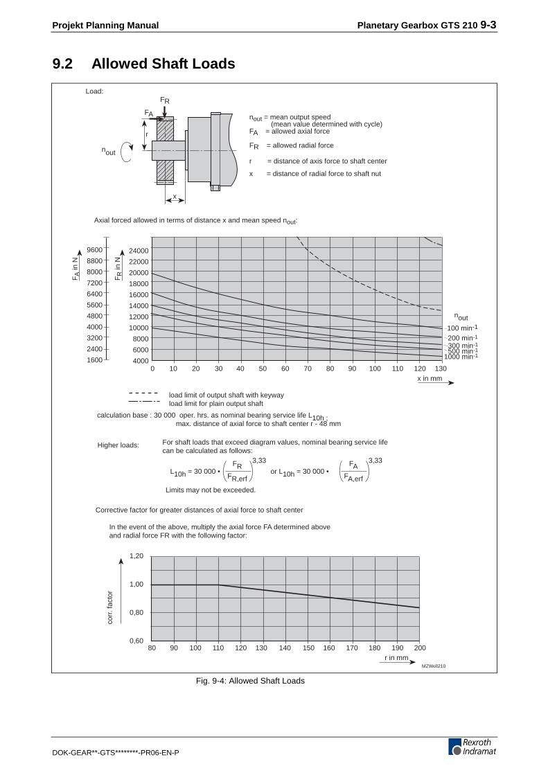
9.2 Allowed Shaft Loads
0 10 20 30x in mm
FR
in N
FA
in N
1,20
1,00
0,80
0,60
r in mm
40
24000
22000
20000
18000
16000
14000
12000
10000
8000
6000
4000
80 90
50 60
100 110 120
70 80
130 140 150
9600
8800
8000
7200
6400
5600
4800
4000
3200
2400
1600
160 170 180
90 100 110 120 130
190 200
corr
. fac
tor
MZWell210
FA
FR
x
r
Load:
nout = mean output speed (mean value determined with cycle)FA = allowed axial force
FR = allowed radial force
r = distance of axis force to shaft center
x = distance of radial force to shaft nut
Axial forced allowed in terms of distance x and mean speed nout:
300 min-1500 min-1
1000 min-1
FRFR,erf
3,33
L10h = 30 000 •
nout
nout
FAFA,erf
3,33
or L10h = 30 000 •
100 min-1
200 min-1
calculation base : 30 000 oper. hrs. as nominal bearing service life L10h ; max. distance of axial force to shaft center r - 48 mm
load limit of output shaft with keywayload limit for plain output shaft
Corrective factor for greater distances of axial force to shaft center
In the event of the above, multiply the axial force FA determined above and radial force FR with the following factor:
For shaft loads that exceed diagram values, nominal bearing service lifecan be calculated as follows:
Limits may not be exceeded.
Higher loads:
Fig. 9-4: Allowed Shaft Loads

9-4 Planetary Gearbox GTS 210 Projekt Planning Manual
DOK-GEAR**-GTS********-PR06-EN-P
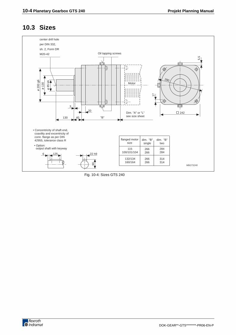
9.3 Sizes
ø 1
80 g
6
ø 1
20
ø 7
5 k6
093100/101/104
112115116
207
"B"
17
105
3
Motor
MBGTS210
254
38
212
17
250
907 20 h9
79,5
5,5
dim. "B"single
flanged motorsize
dim. "B"two
center drill hole
per DIN 332,
sh. 2, Form DR
M20-42
Dim. "A" or "L"see size sheet
• Concentricity of shaft end, coaxility and excentricity of conn. flange as per DIN 42955, tolerance class R
• Option: output shaft with keyway
Oil tapping screws GTS210-M/V(GTS210-C w/o)
132/134 237 284
Fig. 9-5: Sizes GTS210
Projekt Planning Manual Planetary Gearbox GTS 210 9-5
DOK-GEAR**-GTS********-PR06-EN-P
9.4 Available versions
Planetary Motor
Illustration example: Planetary gearbox
Tlgts210.fh7
1
234
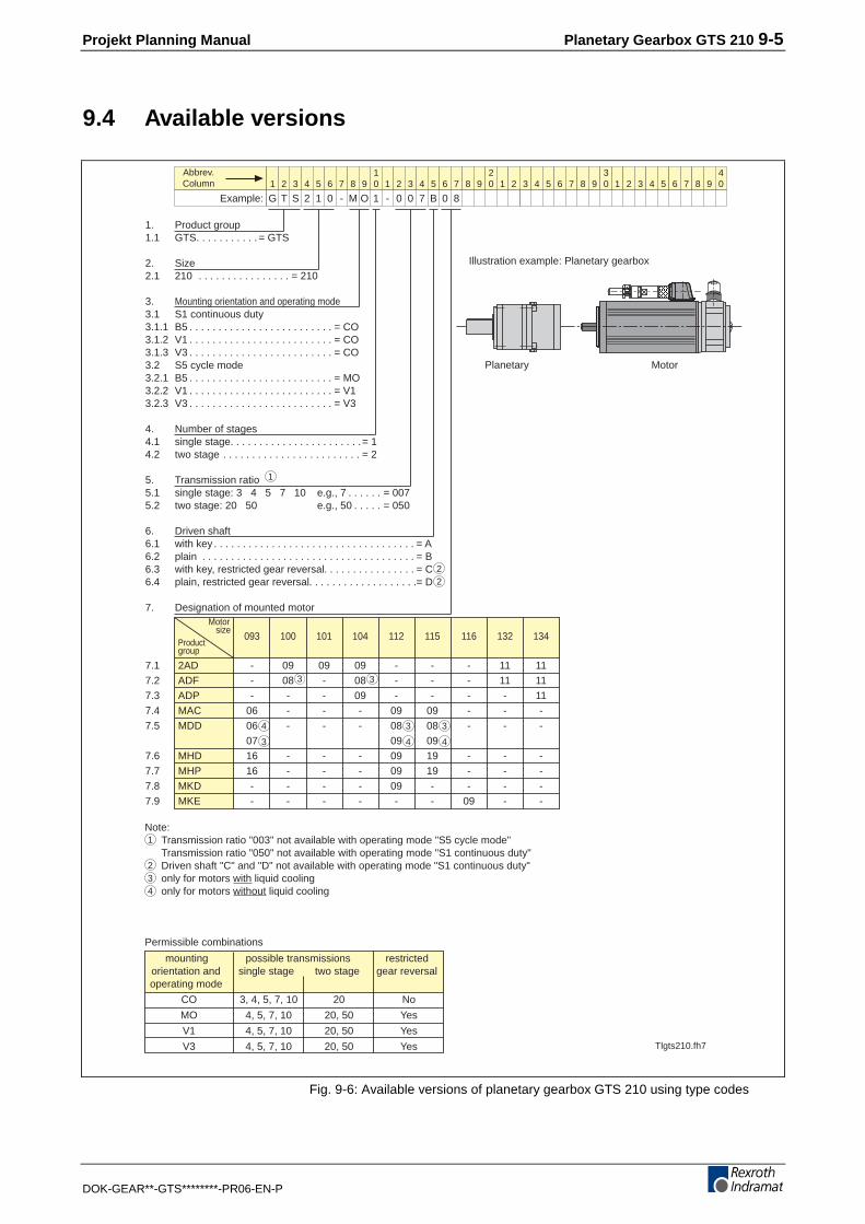
Note:Transmission ratio "003" not available with operating mode "S5 cycle mode"Transmission ratio "050" not available with operating mode "S1 continuous duty"Driven shaft "C" and "D" not available with operating mode "S1 continuous duty"only for motors with liquid coolingonly for motors without liquid cooling
Permissible combinations
mounting possible transmissions restrictedorientation and single stage two stage gear reversaloperating mode
CO 3, 4, 5, 7, 10 20 No
MO 4, 5, 7, 10 20, 50 Yes
V1 4, 5, 7, 10 20, 50 Yes
V3 4, 5, 7, 10 20, 50 Yes
1 2 3 4 6 7 8 9105 1 2 3 4 6 7 8 9
205 1 2 3 4 6 7 8 9
305 1 2 3 4 6 7 8 9
405
Example:
Abbrev.Column
G T S 2 1 0 - M O 1 - 0 0 7 B 0 8
1
22
4 4
3 3
3
4
1. Product group1.1 GTS. . . . . . . . . . . = GTS
2. Size2.1 210 . . . . . . . . . . . . . . . . = 210
3. Mounting orientation and operating mode3.1 S1 continuous duty3.1.1 B5 . . . . . . . . . . . . . . . . . . . . . . . . . = CO3.1.2 V1 . . . . . . . . . . . . . . . . . . . . . . . . . = CO3.1.3 V3 . . . . . . . . . . . . . . . . . . . . . . . . . = CO3.2 S5 cycle mode3.2.1 B5 . . . . . . . . . . . . . . . . . . . . . . . . . = MO3.2.2 V1 . . . . . . . . . . . . . . . . . . . . . . . . . = V13.2.3 V3 . . . . . . . . . . . . . . . . . . . . . . . . . = V3
4. Number of stages4.1 single stage. . . . . . . . . . . . . . . . . . . . . . .= 14.2 two stage . . . . . . . . . . . . . . . . . . . . . . . . = 2
5. Transmission ratio5.1 single stage: 3 4 5 7 10 e.g., 7 . . . . . . = 0075.2 two stage: 20 50 e.g., 50 . . . . . = 050
6. Driven shaft6.1 with key . . . . . . . . . . . . . . . . . . . . . . . . . . . . . . . . . . . = A6.2 plain . . . . . . . . . . . . . . . . . . . . . . . . . . . . . . . . . . . . . = B6.3 with key, restricted gear reversal. . . . . . . . . . . . . . . . = C6.4 plain, restricted gear reversal. . . . . . . . . . . . . . . . . . .= D
7. Designation of mounted motorMotor
sizeProductgroup
093 100 101 104 112 115 116 132 134
7.1 2AD - 09 09 09 - - - 11 117.2 ADF - 08 - 08 - - - 11 117.3 ADP - - - 09 - - - - 117.4 MAC 06 - - - 09 09 - - -7.5 MDD 06 - - - 08 08 - - -
07 09 097.6 MHD 16 - - - 09 19 - - -7.7 MHP 16 - - - 09 19 - - -7.8 MKD - - - - 09 - - - -7.9 MKE - - - - - - 09 - -
3 3
Fig. 9-6: Available versions of planetary gearbox GTS 210 using type codes

9-6 Planetary Gearbox GTS 210 Projekt Planning Manual
DOK-GEAR**-GTS********-PR06-EN-P

10-2 Planetary Gearbox GTS 240 Projekt Planning Manual
DOK-GEAR**-GTS********-PR06-EN-P
10 Planetary Gearbox GTS 240
10.1 Technical Data
Designation Symbol Unit GTS 240-MIV
single-stage two-stage
Ratio i - 4 5 7 10 20 50
max. input speed nin,max min-1 2200 2200 2200 2200 3500 3500
max.
input torque 1) Min,max Nm 876 701 501 280 180 72
max. output speed nout,max min-1 550 440 314 220 110 44
max.
output torque 1) Mout,max Nm 3400 3400 3400 2720 3400 3400
max. output power Pout,max kW 196 157 112 63 39 16
nominal input speed nin,nom. min-1 1000 1000 1500 1500 1900 2100
nominal output torque Mout,nom. Nm 1700 1700 1700 1700 1700 1700
Inertia 2) J kgcm2 146 120 96 83 49 35
1) with max. 1000 cycles/hours
2) moment of inertia of gearbox as relates to input side
Fig. 10-1: Ratio dependent data GTS 240
Designation Symbol Unit GTS 240
single-stage two-stage
Efficiency η % 97 94
Backlash 1) ∆ arcmin ≤ 4 (≤ 2)2) ≤ 6 (≤ 4)2)
Torsional stiffness 3) D Nm/rad 1200000
Service life L10h h >30000
Lubricant - - synthetic oil with viscosity of VG 220
allowable ambienttemperature
TUm °C 0...45
permissible gearhousing temperaturewith MIV version
TG °C-10...+90
Noise level Lp dB (A) ≤ 72 4)
Protection category - - IP 65 5)
Weight m kg 73 76
Mechanicallycombinable withmotor size
100 / 101 / 104 / 115 / 132 / 134 / 160 / 164
1) references gear output side at ±2% nominal output torque or gear and fixed gear input side
2) bracket values apply to limited gear backlash
3) Torsional stiffness of gear or gear output side with fixed gear output side
4) at gear input speed of 3000 min-1
5) output shaft leadthrough excepted which is IP 64
Fig. 10-2: General data GTS 240
Ratio dependent data (only forS5 operating mode possible)
General data

Projekt Planning Manual Planetary Gearbox GTS 240 10-3
DOK-GEAR**-GTS********-PR06-EN-P
10.2 Allowed Shaft Loads
0 10 20 30 40 50 60 70 80 90 100 110 120 130 140 150x in mm
FR
in N
FA
in N
1,20
1,00
0,80
0,60
r in mm
30000
25000
20000
15000
10000
5000
0
100 110 120 130 140 150
12000
10000
8000
6000
4000
2000
0
160 170 180 190 200 210 220
corr
. fac
tor
MZWell240
FA
FR
x
r
Load:
nout = mean output speed (mean value determined with cycle)FA = allowed axial force
FR = allowed radial force
r = distance of axis force to shaft center
x = distance of radial force to shaft nut
Axial forced allowed in terms of distance x and mean speed nout:
FRFR,erf
3,33
100 min-1
200 min-1
300 min-1
500 min-1
1000 min-1
L10h = 30 000 •
nout
nout
FAFA,erf
3,33
or L10h = 30 000 •
calculation base : 30 000 oper. hrs. as nominal bearing service life L10h ; max. distance of axial force to shaft center r - 48 mm
load limit of output shaft with keywayload limit for plain output shaft
Corrective factor for greater distances of axial force to shaft center
In the event of the above, multiply the axial force FA determined above and radial force FR with the following factor:
For shaft loads that exceed diagram values, nominal bearing service lifecan be calculated as follows:
Limits may not be exceeded.
Higher loads:
Fig. 10-3: Allowable shaft load GTS 240
10-4 Planetary Gearbox GTS 240 Projekt Planning Manual
DOK-GEAR**-GTS********-PR06-EN-P
10.3 Sizesø
200
g6
ø 1
30
ø 8
5 k6
115100/101/104
266266
"B"
20
130
3
Motor
MBGTS240
284284
40
242
17
290
1256 22 h9
90
5,5
dim. "B"single
flanged motorsize
dim. "B"two
center drill hole
per DIN 332,
sh. 2, Form DR
M20-42
Dim. "A" or "L"see size sheet
• Concentricity of shaft end, coaxility and excentricity of conn. flange as per DIN 42955, tolerance class R
• Option: output shaft with keyway
Oil tapping screws
132/134160/164
266266
314314
Fig. 10-4: Sizes GTS 240

Projekt Planning Manual Planetary Gearbox GTS 240 10-5
DOK-GEAR**-GTS********-PR06-EN-P
10.4 Available versions
3
1
2
3
3
123
1 2 3 4 6 7 8 9105 1 2 3 4 6 7 8 9
205 1 2 3 4 6 7 8 9
305 1 2 3 4 6 7 8 9
405
Example:
Abbrev.Column
G T S 2 4 0 - M O 1 - 0 0 7 A 0 9
Planetary Motor
Tlgts240.fh7
1 1
1. Product group1.1 GTS . . . . . . . . . . = GTS
2. Size2.1 240 . . . . . . . . . . . . . . . . . = 240
3. Mounting orientation3.1 B5 . . . . . . . . . . . . . . . . . . . . . . . . . = MO3.2 V1 . . . . . . . . . . . . . . . . . . . . . . . . . = V13.3 V3 . . . . . . . . . . . . . . . . . . . . . . . . . = V3
4. Number of stages4.1 single stage. . . . . . . . . . . . . . . . . . . . . . .= 14.2 two stage . . . . . . . . . . . . . . . . . . . . . . . . = 2
5. Transmission ratio5.1 single stage: 4 5 7 10 e.g., 7 . . . . . . = 0075.2 two stage: 20 50 e.g., 50 . . . . . = 050
6. Driven shaft6.1 with key . . . . . . . . . . . . . . . . . . . . . . . . . . . . . . . . . . = A6.2 plain . . . . . . . . . . . . . . . . . . . . . . . . . . . . . . . . . . . . . = B6.3 with key, restricted gear reversal. . . . . . . . . . . . . . . . = C6.4 plain, restricted gear reversal. . . . . . . . . . . . . . . . . . .= D
7. Designation of mounted motorMotor
sizeProductgroup
100 101 104 115 132 134 160 164
7.1 2AD 09 09 09 - 11 11 12 127.2 ADF 08 - 08 - 11 11 - -7.3 ADP - - 09 - - 11 - 127.4 MAC - - - 09 - - - -7.5 MDD - - - 08 - -
- 09 - - - -7.6 MHD - - - 19 - - - -7.7 MHP - - - 19 - - - -
Note:only for motors with liquid coolingonly for motors without liquid coolingonly available with single-stage gearbox
Illustration example: Planetary gearbox
Fig. 10-5: Available versions of planetary gearbox GTS 240 using type codes

Projekt Planning Manual Order Designations 11-1
DOK-GEAR**-GTS********-PR06-EN-P
11 Order DesignationsThe GTS has to be specified on the order as a subitem of the AC motor.A complete unit made up of the GTS gearbox and AC motor is what isalways delivered.
When ordering the motor it is also necessary to note that the output shaftof the motor must always be a plain shaft
An example of an order:
1 1 AC motor
type: MDD 093B-N-020-N2L-110GB0
1.1 1 Planetary gearbox
type: GTS 140-M01-005B06
mounted to item 1

11-2 Order Designations Projekt Planning Manual
DOK-GEAR**-GTS********-PR06-EN-P

Projekt Planning Manual Service Notes 12-1
DOK-GEAR**-GTS********-PR06-EN-P
12 Service Notes
12.1 Contacting Customer Service
During the conventional office hours, please contact your nearestIndramat service office.
Outside of the conventional hours, Indramat Customer Service can bereached at the following service hotline phone numbers at the specifiedhours:
Phone no. 0172 - 660 040 6 or 0171 - 333 882 6
Monday - Friday 17 00
- 23 00
CET
Saturday 8 00
- 20 00
CET
Sundays and holidays 9 00
- 19 00
CET
To ensure a quick elimination of the problem, please note the followingbefore phoning in:
• the type codes of the controller, motors and gearbox
• the fault
• and any error or diagnostics readings
Note: When returning the gearbox, please enclose the Fault Reportthat can be found in section 12.2. Just copy it and fill it out.
Service Hotline

12-2 Service Notes Projekt Planning Manual
DOK-GEAR**-GTS********-PR06-EN-P
12.2 Faulty Report
oper.mode. S reverse modeambient temperatur: ° Coutput: pinion for rack drive belt pulley own output component other
Name: Co. / Loc. Date
Gearbox:
Motor
Serial no.:
Serial no.:
Machine: Mach. no.: Manufacturer:
Comm. date.: Failure date.: Oper. time
Fault Cause
increased noisegearbox not sealedgears blockedoutput shaft breakother
unknownfaulty usecollisionother
Describe problem:
Operating conditions
TBstör
average operating dur./date: hcyklen/hourmounted: horizontal vertical, output shaft up vertical, output shaft down other
Fig. 12-1: Faulty Report

Projekt Planning Manual Index 13-1
DOK-GEAR**-GTS********-PR06-EN-P
13 Index
AAmbient Conditions 3-1Applications 1-1
CConstant Velocity with Dead Time 2-2Constant Velocity without Dead Time (S1) 2-3Construction, Mounting Orientation 3-5
DDimensioning 2-1Drive-determining Variables 2-4
FFaulty Report 12-2Functional principle 1-1
GGearbox used in areas subject to explosion hazards 3-2
HHousing Finish 3-3
LLayout Criteria 2-4Lubrication 3-6
MMaximum Ambient Temperature and Installation Elevation 3-1Mechanical Features 3-5Mounting Output Components 3-7
OOperating mode S1 (Continous operation) 3-3Operating mode S5 (Intermittent mode) 3-4Operating reliability 1-1Order Designations 11-1Output Shaft 3-6
PPlanetary Gearbox GTS 060 4-1Planetary Gearbox GTS 075 5-1Planetary Gearbox GTS 100 6-1Planetary Gearbox GTS 140 7-1Planetary Gearbox GTS 180 8-1Planetary Gearbox GTS 210 9-1Planetary Gearbox GTS 240 10-2Possible Combinations of GTS Planetary Gearboxes with AC Motors 3-8Protection Category 3-2

13-2 Index Projekt Planning Manual
DOK-GEAR**-GTS********-PR06-EN-P
SSales & Service Facilities 14-1Service Notes 12-1Shaft Load 3-6
TThe Selection Process 2-4Trapezoidal Operations with Dead Time 2-2Triangular Operation with Dead Time 2-1

Projekt Planning Manual Kundenbetreuungsstellen - Sales & Service Facilities 14-1
DOK-GEAR**-GTS********-PR06-EN-P
14 Kundenbetreuungsstellen - Sales & ServiceFacilities
Deutschland – Germany vom Ausland: (0) nach Landeskennziffer weglassen!!from abroad: don’t dial (0) after country code!
Vertriebsgebiet Mitte SALES
Germany Centre Service
Rexroth Indramat GmbHBgm.-Dr.-Nebel-Str. 297816 Lohr am Main
Telefon: +49 (0)9352/40-0Telefax: +49 (0)9352/40-4885
Vertriebsgebiet Mitte SALES
Germany Centre Service
Mannesmann Rexroth AGGesch.ber. Rexroth IndramatLilistraße 14-1863067 Offenbach
Telefon: +49 (0) 69/82 00 90-0Telefax: +49 (0) 69/82 00 90-80
Vertriebsgebiet Ost SALES
Germany East Service
Rexroth Indramat GmbHBeckerstraße 3109120 Chemnitz
Telefon: +49 (0)371/35 55-0Telefax: +49 (0)371/35 55-333
Vertriebsgebiet Ost SALES
Germany East Service
Mannesmann Rexroth AGGB Rexroth Indramat GmbHHolzhäuser Str. 12204299 Leipzig
Telefon: +49 (0)341/86 77-0Telefax: +49 (0)341/86 77-219
Vertriebsgebiet Süd SALES
Germany South Service
Rexroth Indramat GmbHRidlerstraße 7580339 München
Telefon: +49 (0)89/540138-30Telefax: +49 (0)89/[email protected]
Gebiet Südwest SALES
Germany South-West Service
Mannesmann Rexroth AGVertrieb Deutschland – VD-BIGeschäftsbereich Rexroth IndramatRegionalzentrum SüdwestRingstrasse 70 / Postfach 114470736 Fellbach / 70701 Fellbach
Tel.: +49 (0)711/57 61–100Fax: +49 (0)711/57 61–125
Vertriebsgebiet Nord SALES
Germany North Service
Rexroth Indramat GmbHKieler Straße 21222525 Hamburg
Telefon: +49 (0)40/85 31 57-0Telefax: +49 (0)40/85 31 57-15
Vertriebsgebiet Nord SALES
Germany North Service
Mannesmann Rexroth AGVertriebsniederlassung Region NordGesch.ber. Rexroth IndramatWalsroder Str. 9330853 Langenhagen
Telefon: +49 (0) 511/72 66 57-0Telefax: +49 (0) 511/72 66 57-93
Vertriebsgebiet West SALES
Germany West Service
Mannesmann Rexroth AGVertrieb DeutschlandRegionalzentrum WestBorsigstrasse 15D - 40880 Ratingen
Telefon: +49 (0)2102/409-0Telefax: +49 (0)2102/409-406
SERVICE - Hotline - 7 Tage / 24h -
H E L P D E S KMO – FR - von 7 – 17 UhrTelefax +49 (0)9352/40-4941Telefon +49 (0)9352/40- Bernard A. -4894 Kolb R. -4922 Pfeffermann O. -4808 Roeper P. -4359 Scheiner W. -4921
AU S S E R H ALB dieser Zeit:Telefon: +49 (0)172/660 04 06oder/orTelefon: +49 (0)171/333 88 26
ERSATZTEIL - Hotline
♦ nur an Werktagen
♦ von 15 -18 Uhr
Tel. +49 (0) 93 52/40 42 22
Kundenbetreuungsstellen in Deutschland - Service agencies in Germany
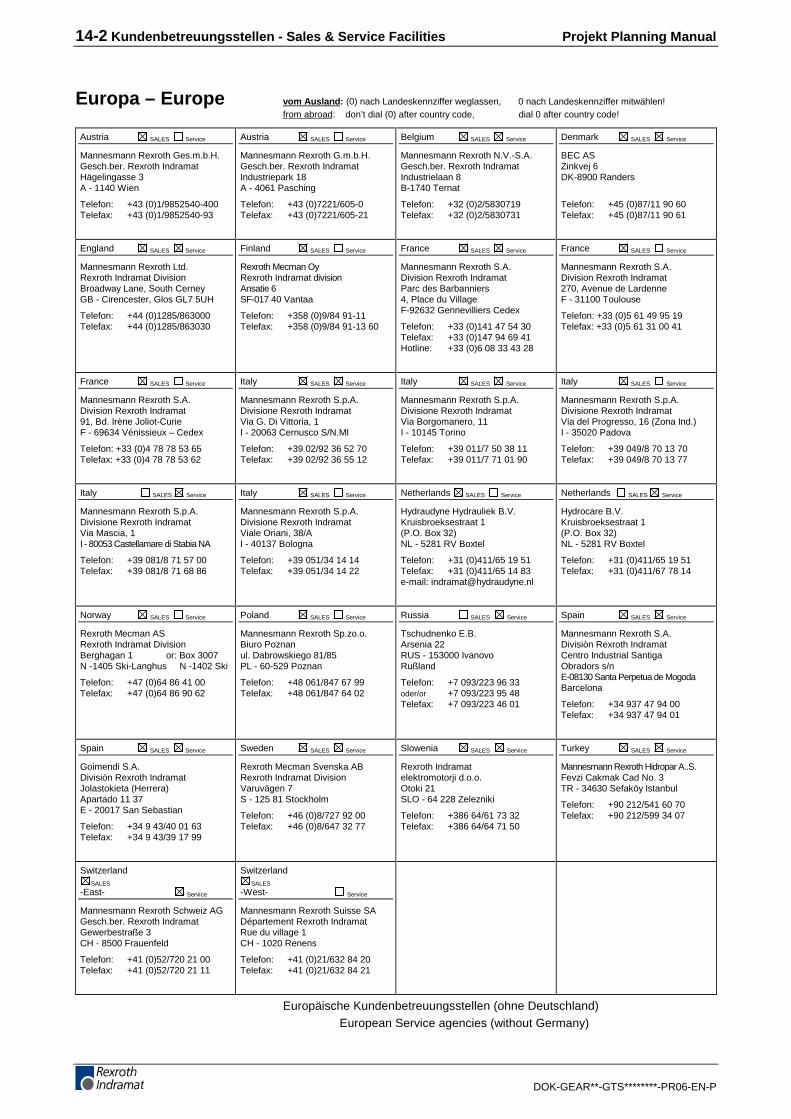
14-2 Kundenbetreuungsstellen - Sales & Service Facilities Projekt Planning Manual
DOK-GEAR**-GTS********-PR06-EN-P
Europa – Europe vom Ausland: (0) nach Landeskennziffer weglassen, 0 nach Landeskennziffer mitwählen!from abroad: don’t dial (0) after country code, dial 0 after country code!
Austria SALES Service
Mannesmann Rexroth Ges.m.b.H.Gesch.ber. Rexroth IndramatHägelingasse 3A - 1140 Wien
Telefon: +43 (0)1/9852540-400Telefax: +43 (0)1/9852540-93
Austria SALES Service
Mannesmann Rexroth G.m.b.H.Gesch.ber. Rexroth IndramatIndustriepark 18A - 4061 Pasching
Telefon: +43 (0)7221/605-0Telefax: +43 (0)7221/605-21
Belgium SALES Service
Mannesmann Rexroth N.V.-S.A.Gesch.ber. Rexroth IndramatIndustrielaan 8B-1740 Ternat
Telefon: +32 (0)2/5830719Telefax: +32 (0)2/5830731
Denmark SALES Service
BEC ASZinkvej 6DK-8900 Randers
Telefon: +45 (0)87/11 90 60Telefax: +45 (0)87/11 90 61
England SALES Service
Mannesmann Rexroth Ltd.Rexroth Indramat DivisionBroadway Lane, South CerneyGB - Cirencester, Glos GL7 5UH
Telefon: +44 (0)1285/863000Telefax: +44 (0)1285/863030
Finland SALES Service
Rexroth Mecman OyRexroth Indramat divisionAnsatie 6SF-017 40 Vantaa
Telefon: +358 (0)9/84 91-11Telefax: +358 (0)9/84 91-13 60
France SALES Service
Mannesmann Rexroth S.A.Division Rexroth IndramatParc des Barbanniers4, Place du VillageF-92632 Gennevilliers Cedex
Telefon: +33 (0)141 47 54 30Telefax: +33 (0)147 94 69 41Hotline: +33 (0)6 08 33 43 28
France SALES Service
Mannesmann Rexroth S.A.Division Rexroth Indramat270, Avenue de LardenneF - 31100 Toulouse
Telefon: +33 (0)5 61 49 95 19Telefax: +33 (0)5 61 31 00 41
France SALES Service
Mannesmann Rexroth S.A.Division Rexroth Indramat91, Bd. Irène Joliot-CurieF - 69634 Vénissieux – Cedex
Telefon: +33 (0)4 78 78 53 65Telefax: +33 (0)4 78 78 53 62
Italy SALES Service
Mannesmann Rexroth S.p.A.Divisione Rexroth IndramatVia G. Di Vittoria, 1I - 20063 Cernusco S/N.MI
Telefon: +39 02/92 36 52 70Telefax: +39 02/92 36 55 12
Italy SALES Service
Mannesmann Rexroth S.p.A.Divisione Rexroth IndramatVia Borgomanero, 11I - 10145 Torino
Telefon: +39 011/7 50 38 11Telefax: +39 011/7 71 01 90
Italy SALES Service
Mannesmann Rexroth S.p.A.Divisione Rexroth IndramatVia del Progresso, 16 (Zona Ind.)I - 35020 Padova
Telefon: +39 049/8 70 13 70Telefax: +39 049/8 70 13 77
Italy SALES Service
Mannesmann Rexroth S.p.A.Divisione Rexroth IndramatVia Mascia, 1I - 80053 Castellamare di Stabia NA
Telefon: +39 081/8 71 57 00Telefax: +39 081/8 71 68 86
Italy SALES Service
Mannesmann Rexroth S.p.A.Divisione Rexroth IndramatViale Oriani, 38/AI - 40137 Bologna
Telefon: +39 051/34 14 14Telefax: +39 051/34 14 22
Netherlands SALES Service
Hydraudyne Hydrauliek B.V.Kruisbroeksestraat 1(P.O. Box 32)NL - 5281 RV Boxtel
Telefon: +31 (0)411/65 19 51Telefax: +31 (0)411/65 14 83e-mail: [email protected]
Netherlands SALES Service
Hydrocare B.V.Kruisbroeksestraat 1(P.O. Box 32)NL - 5281 RV Boxtel
Telefon: +31 (0)411/65 19 51Telefax: +31 (0)411/67 78 14
Norway SALES Service
Rexroth Mecman ASRexroth Indramat DivisionBerghagan 1 or: Box 3007N -1405 Ski-Langhus N -1402 Ski
Telefon: +47 (0)64 86 41 00Telefax: +47 (0)64 86 90 62
Poland SALES Service
Mannesmann Rexroth Sp.zo.o.Biuro Poznanul. Dabrowskiego 81/85PL - 60-529 Poznan
Telefon: +48 061/847 67 99Telefax: +48 061/847 64 02
Russia SALES Service
Tschudnenko E.B.Arsenia 22RUS - 153000 IvanovoRußland
Telefon: +7 093/223 96 33oder/or +7 093/223 95 48Telefax: +7 093/223 46 01
Spain SALES Service
Mannesmann Rexroth S.A.Divisiòn Rexroth IndramatCentro Industrial SantigaObradors s/nE-08130 Santa Perpetua de MogodaBarcelona
Telefon: +34 937 47 94 00Telefax: +34 937 47 94 01
Spain SALES Service
Goimendi S.A.División Rexroth IndramatJolastokieta (Herrera)Apartado 11 37E - 20017 San Sebastian
Telefon: +34 9 43/40 01 63Telefax: +34 9 43/39 17 99
Sweden SALES Service
Rexroth Mecman Svenska ABRexroth Indramat DivisionVaruvägen 7S - 125 81 Stockholm
Telefon: +46 (0)8/727 92 00Telefax: +46 (0)8/647 32 77
Slowenia SALES Service
Rexroth Indramatelektromotorji d.o.o.Otoki 21SLO - 64 228 Zelezniki
Telefon: +386 64/61 73 32Telefax: +386 64/64 71 50
Turkey SALES Service
Mannesmann Rexroth Hidropar A..S.Fevzi Cakmak Cad No. 3TR - 34630 Sefaköy Istanbul
Telefon: +90 212/541 60 70Telefax: +90 212/599 34 07
SwitzerlandSALES
-East- Service
Mannesmann Rexroth Schweiz AGGesch.ber. Rexroth IndramatGewerbestraße 3CH - 8500 Frauenfeld
Telefon: +41 (0)52/720 21 00Telefax: +41 (0)52/720 21 11
SwitzerlandSALES
-West- Service
Mannesmann Rexroth Suisse SADépartement Rexroth IndramatRue du village 1CH - 1020 Renens
Telefon: +41 (0)21/632 84 20Telefax: +41 (0)21/632 84 21
Europäische Kundenbetreuungsstellen (ohne Deutschland)European Service agencies (without Germany)
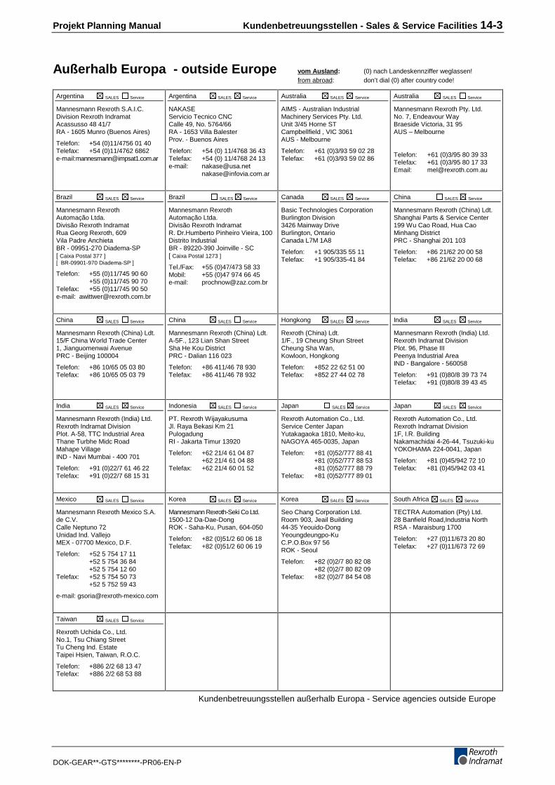
Projekt Planning Manual Kundenbetreuungsstellen - Sales & Service Facilities 14-3
DOK-GEAR**-GTS********-PR06-EN-P
Außerhalb Europa - outside Europe vom Ausland: (0) nach Landeskennziffer weglassen!from abroad: don’t dial (0) after country code!
Argentina SALES Service
Mannesmann Rexroth S.A.I.C.Division Rexroth IndramatAcassusso 48 41/7RA - 1605 Munro (Buenos Aires)
Telefon: +54 (0)11/4756 01 40Telefax: +54 (0)11/4762 6862e-mail:[email protected]
Argentina SALES Service
NAKASEServicio Tecnico CNCCalle 49, No. 5764/66RA - 1653 Villa BalesterProv. - Buenos Aires
Telefon: +54 (0) 11/4768 36 43Telefax: +54 (0) 11/4768 24 13e-mail: [email protected]
Australia SALES Service
AIMS - Australian IndustrialMachinery Services Pty. Ltd.Unit 3/45 Horne STCampbellfield , VIC 3061AUS - Melbourne
Telefon: +61 (0)3/93 59 02 28Telefax: +61 (0)3/93 59 02 86
Australia SALES Service
Mannesmann Rexroth Pty. Ltd.No. 7, Endeavour WayBraeside Victoria, 31 95AUS – Melbourne
Telefon: +61 (0)3/95 80 39 33Telefax: +61 (0)3/95 80 17 33Email: [email protected]
Brazil SALES Service
Mannesmann RexrothAutomação Ltda.Divisão Rexroth IndramatRua Georg Rexroth, 609Vila Padre AnchietaBR - 09951-270 Diadema-SP[ Caixa Postal 377 ][ BR-09901-970 Diadema-SP ]
Telefon: +55 (0)11/745 90 60+55 (0)11/745 90 70
Telefax: +55 (0)11/745 90 50e-mail: [email protected]
Brazil SALES Service
Mannesmann RexrothAutomação Ltda.Divisão Rexroth IndramatR. Dr.Humberto Pinheiro Vieira, 100Distrito IndustrialBR - 89220-390 Joinville - SC[ Caixa Postal 1273 ]
Tel./Fax: +55 (0)47/473 58 33Mobil: +55 (0)47 974 66 45e-mail: [email protected]
Canada SALES Service
Basic Technologies CorporationBurlington Division3426 Mainway DriveBurlington, OntarioCanada L7M 1A8
Telefon: +1 905/335 55 11Telefax: +1 905/335-41 84
China SALES Service
Mannesmann Rexroth (China) Ldt.Shanghai Parts & Service Center199 Wu Cao Road, Hua CaoMinhang DistrictPRC - Shanghai 201 103
Telefon: +86 21/62 20 00 58Telefax: +86 21/62 20 00 68
China SALES Service
Mannesmann Rexroth (China) Ldt.15/F China World Trade Center1, Jianguomenwai AvenuePRC - Beijing 100004
Telefon: +86 10/65 05 03 80Telefax: +86 10/65 05 03 79
China SALES Service
Mannesmann Rexroth (China) Ldt.A-5F., 123 Lian Shan StreetSha He Kou DistrictPRC - Dalian 116 023
Telefon: +86 411/46 78 930Telefax: +86 411/46 78 932
Hongkong SALES Service
Rexroth (China) Ldt.1/F., 19 Cheung Shun StreetCheung Sha Wan,Kowloon, Hongkong
Telefon: +852 22 62 51 00Telefax: +852 27 44 02 78
India SALES Service
Mannesmann Rexroth (India) Ltd.Rexroth Indramat DivisionPlot. 96, Phase IIIPeenya Industrial AreaIND - Bangalore - 560058
Telefon: +91 (0)80/8 39 73 74Telefax: +91 (0)80/8 39 43 45
India SALES Service
Mannesmann Rexroth (India) Ltd.Rexroth Indramat DivisionPlot. A-58, TTC Industrial AreaThane Turbhe Midc RoadMahape VillageIND - Navi Mumbai - 400 701
Telefon: +91 (0)22/7 61 46 22Telefax: +91 (0)22/7 68 15 31
Indonesia SALES Service
PT. Rexroth WijayakusumaJl. Raya Bekasi Km 21PulogadungRI - Jakarta Timur 13920
Telefon: +62 21/4 61 04 87+62 21/4 61 04 88
Telefax: +62 21/4 60 01 52
Japan SALES Service
Rexroth Automation Co., Ltd.Service Center JapanYutakagaoka 1810, Meito-ku,NAGOYA 465-0035, Japan
Telefon: +81 (0)52/777 88 41+81 (0)52/777 88 53+81 (0)52/777 88 79
Telefax: +81 (0)52/777 89 01
Japan SALES Service
Rexroth Automation Co., Ltd.Rexroth Indramat Division1F, I.R. BuildingNakamachidai 4-26-44, Tsuzuki-kuYOKOHAMA 224-0041, Japan
Telefon: +81 (0)45/942 72 10Telefax: +81 (0)45/942 03 41
Mexico SALES Service
Mannesmann Rexroth Mexico S.A.de C.V.Calle Neptuno 72Unidad Ind. VallejoMEX - 07700 Mexico, D.F.
Telefon: +52 5 754 17 11+52 5 754 36 84+52 5 754 12 60
Telefax: +52 5 754 50 73+52 5 752 59 43
e-mail: [email protected]
Korea SALES Service
Mannesmann Rexroth-Seki Co Ltd.1500-12 Da-Dae-DongROK - Saha-Ku, Pusan, 604-050
Telefon: +82 (0)51/2 60 06 18Telefax: +82 (0)51/2 60 06 19
Korea SALES Service
Seo Chang Corporation Ltd.Room 903, Jeail Building44-35 Yeouido-DongYeoungdeungpo-KuC.P.O.Box 97 56ROK - Seoul
Telefon: +82 (0)2/7 80 82 08+82 (0)2/7 80 82 09
Telefax: +82 (0)2/7 84 54 08
South Africa SALES Service
TECTRA Automation (Pty) Ltd.28 Banfield Road,Industria NorthRSA - Maraisburg 1700
Telefon: +27 (0)11/673 20 80Telefax: +27 (0)11/673 72 69
Taiwan SALES Service
Rexroth Uchida Co., Ltd.No.1, Tsu Chiang StreetTu Cheng Ind. EstateTaipei Hsien, Taiwan, R.O.C.
Telefon: +886 2/2 68 13 47Telefax: +886 2/2 68 53 88
Kundenbetreuungsstellen außerhalb Europa - Service agencies outside Europe

14-4 Kundenbetreuungsstellen - Sales & Service Facilities Projekt Planning Manual
DOK-GEAR**-GTS********-PR06-EN-P


267635
IndramatRexroth
Prin
ted
in G
erm
any