Plan of Construction - nunavuttenders.ca - Addendum 1 - Ba… · Plan of Construction Operations...
30
Transcript of Plan of Construction - nunavuttenders.ca - Addendum 1 - Ba… · Plan of Construction Operations...


Plan of Construction Operations (PCO)
Airport: Baker Lake Airport Project: Renovation to the Main Terminal Building
Government of Nunavut Project Number XXX
Prepared for Transport Canada
Prepared by Nunavut Airports, Government of Nunavut
March, 2017

PLAN OF CONSTRUCTION OPERATIONS Baker Lake Airport – Renovation to the Main Terminal Building
Contents
1. INTRODUCTION ............................................................................................. 1
1.1 Project Description .................................................................................................................... 1
1.2 Project Summary ....................................................................................................................... 1
1.3 The Airport Environment ........................................................................................................... 1
1.4 Security ...................................................................................................................................... 2
2. CONSTRUCTION OPERATIONS PLAN AND SCHEDULE ..................................... 2
2.1 Construction .............................................................................................................................. 2
2.2 Construction Access Routes ...................................................................................................... 2
2.3 Safety Fencing/Barricades ......................................................................................................... 2
2.4 F.O.D. Control Program ............................................................................................................. 3
2.5 Scope of Work and Scheduling .................................................................................................. 3
2.6 Proposed Construction Staging ................................................................................................. 3
3. COMMUNICATION ........................................................................................ 4
3.1 Transport Canada Aerodrome Safety ........................................................................................ 4
3.2 NAV CANADA ............................................................................................................................. 4
3.3 Issuance of Communications ..................................................................................................... 4
3.4 Line of Communication Diagram ............................................................................................... 5
4. AIRSIDE SAFETY AND PROCEDURES ............................................................... 5
4.1 General ...................................................................................................................................... 5
4.2 Aerodrome Standards and Recommended Practice ................................................................. 5
4.3 Vehicle Safety Requirements .................................................................................................... 6
4.4 NOTAMS and Responsibilities ................................................................................................... 6
5. APPROVAL .................................................................................................... 7
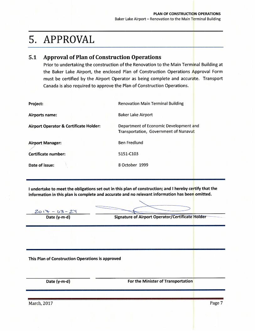
5.1 Approval of Plan of Construction Operations ........................................................................... 7
March, 2017 Page i

PLAN OF CONSTRUCTION OPERATIONS Baker Lake Airport – Renovation to the Main Terminal Building
1. INTRODUCTION 1.1 Project Description
Site Name: Baker Lake Airport Project: Baker Lake Airport Improvements Start Date: July 2017 Finish Date: Dec 2017 Originator: Fred Fast Manager, Standards and Program Development Economic, Development and Transportation Government of Nunavut Ph: (867) 645-8212 Fax: (867) 645-8246 Email: [email protected] Other Contact: Todd Mackay Director, Nunavut Airports Economic, Development and Transportation Government of Nunavut Ph: (867)645-8203 Fax: (867)645-8246 Email: [email protected]
1.2 Project Summary A contractor to be determined will be awarded a contract by the Government of Nunavut to make modifications to the existing Baker Lake Airport Terminal Building. The scope of work will be conducted in such manner that the work will take place adjacent to airside operations.
1.3 The Airport Environment The airport operational environment is extremely dynamic and involves various stakeholders, including Transport Canada, the users, NAV CANADA, the operator (Government of Nunavut), airport staff, security, and many others. In addition, the airport environment is highly regulated in the interest of public safety. As such, any deviations from standard operating procedures are carefully considered and subject to detailed review and input from the stakeholders and regulators.
March, 2017 Page 1
PLAN OF CONSTRUCTION OPERATIONS Baker Lake Airport – Renovation to the Main Terminal Building
1.4 Security
All airport security procedures will remain in effect throughout the construction period.
2. CONSTRUCTION OPERATIONS PLAN AND SCHEDULE
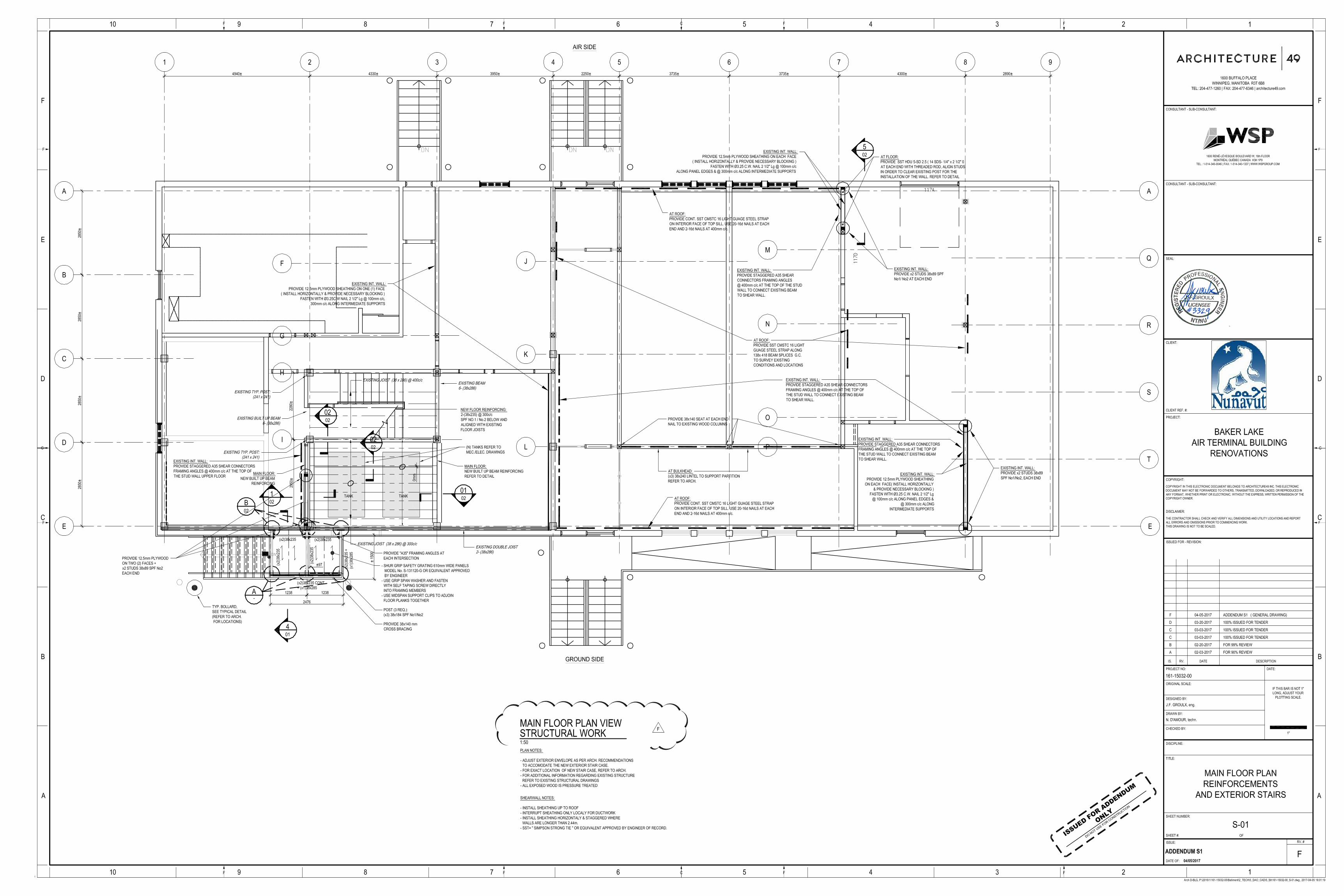
2.1 Construction The renovation to the Terminal Building consists of major interior alterations to the existing floor plan. The renovation will require access to terminal building doors located airside.
2.2 Construction Access Routes Access to the construction site will be from “groundside”.
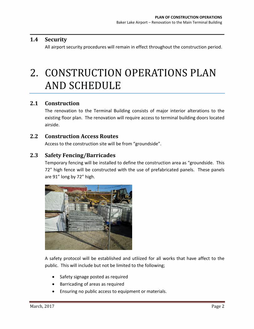
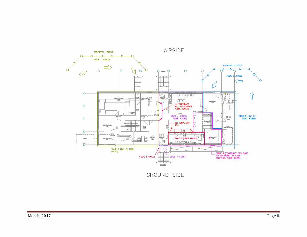
2.3 Safety Fencing/Barricades Temporary fencing will be installed to define the construction area as “groundside. This 72” high fence will be constructed with the use of prefabricated panels. These panels are 91” long by 72” high.
A safety protocol will be established and utliized for all works that have affect to the public. This will include but not be limited to the following;
• Safety signage posted as required • Barricading of areas as required • Ensuring no public access to equipment or materials.
March, 2017 Page 2

PLAN OF CONSTRUCTION OPERATIONS Baker Lake Airport – Renovation to the Main Terminal Building
• Providing a daily check of the constuction area to ensure compliance to policies. • Ensure conformance to the “Nunuvat Occupation and Safety Act”
2.4 F.O.D. Control Program The Baker Lake Airport has a stringent Foreign Object Debris (F.O.D.) Control Program in place.
Under no circumstances will the Contractor be permitted to dispose of any F.O.D. while on site. F.O.D. will be monitored by the airport maintainer, and by the Contractor. Any F.O.D. observed must be removed immediately in accordance with the F.O.D. Control Program. Details of the F.O.D. control program shall be reviewed with the airport maintainer prior to the commencement of the work.
2.5 Scope of Work and Scheduling The work generally involves the following:
• Wood Framed Interior Walls • Interior Finishes • Mechanical/Electrical
The planned construction period is approximately July, 2017 until December, 2017.
2.6 Proposed Construction Staging A site layout plan with minor adustements made to the groundside/airside fence will allow for all constuction activies to take place groundside.
Exterior works operations will take place during daytime hours from 7AM to 5:30PM daily including weekends.
Interior work will take place in off peak times to allow for minimum interruption of Public access. The work will take place from 7AM to 11AM and 3PM to 12AM. There may be circumstances where the work schedule changes to accommodate certain activities, if this occurs supervision shall inform the Airport Manager in advance.
There will be no cranes required to perform any of the project related scope. At no time will any of the equipment utilized for construction activities cross the airside plane of the fencing.
All stored project materials and equipment will be stored securely groundside so that they are protected from winds removing the risk of propelling to airside.
March, 2017 Page 3

PLAN OF CONSTRUCTION OPERATIONS Baker Lake Airport – Renovation to the Main Terminal Building
3. COMMUNICATION 3.1 Transport Canada Aerodrome Safety
Transport Canada Aerodrome Safety is interested in ensuring the continued safe operation of the airport and that all applicable regulations, standards and recommended practices are complied with. Periodic inspections may be conducted during the construction period to ensure the intent of this Plan of Construction is followed.
Only the Airport Manager or Manager, Facilities Engineering and other designated Nunavut Airports’ staff shall communicate with Transport Canada.
3.2 NAV CANADA NAV CANADA provides local Flight Information Services through the CARS O/C (Community Aerodrome Radio Station Observer / Communicator). NAV CANADA personnel require a clear understanding of the status of the project at all times.
Only the Airport Site Representative, or as directed, the Contractor, shall communicate with NAV CANADA on matters related to this project.
3.3 Issuance of Communications Written directives will be issued by the Project Manager to the Contractor if a question requires immediate attention that cannot wait for the next project meeting.
March, 2017 Page 4
PLAN OF CONSTRUCTION OPERATIONS Baker Lake Airport – Renovation to the Main Terminal Building
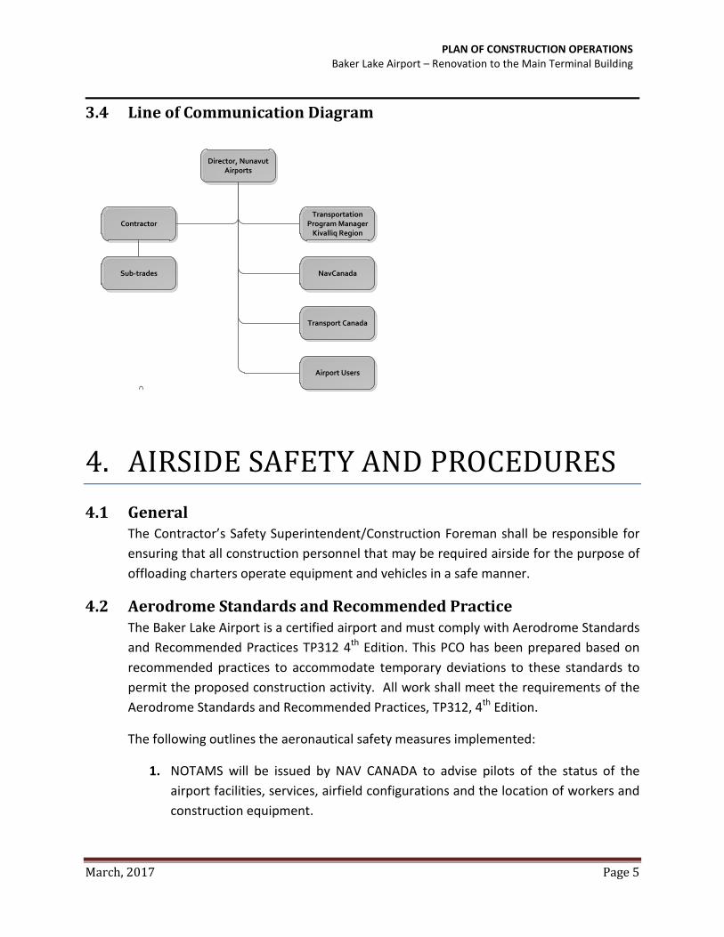
3.4 Line of Communication Diagram
Director, Nunavut
Airports
Contractor
Sub-trades
Transportation
Program Manager Kivalliq Region
NavCanada
Transport Canada
Airport Users
4. AIRSIDE SAFETY AND PROCEDURES 4.1 General
The Contractor’s Safety Superintendent/Construction Foreman shall be responsible for ensuring that all construction personnel that may be required airside for the purpose of offloading charters operate equipment and vehicles in a safe manner.
4.2 Aerodrome Standards and Recommended Practice The Baker Lake Airport is a certified airport and must comply with Aerodrome Standards and Recommended Practices TP312 4th Edition. This PCO has been prepared based on recommended practices to accommodate temporary deviations to these standards to permit the proposed construction activity. All work shall meet the requirements of the Aerodrome Standards and Recommended Practices, TP312, 4th Edition.
The following outlines the aeronautical safety measures implemented:
1. NOTAMS will be issued by NAV CANADA to advise pilots of the status of the airport facilities, services, airfield configurations and the location of workers and construction equipment.
March, 2017 Page 5

PLAN OF CONSTRUCTION OPERATIONS Baker Lake Airport – Renovation to the Main Terminal Building
4.3 Vehicle Safety Requirements
All vehicles that will be operated or driven while offloading cargo must be equipped with a rotating warning light that will be turned on while the vehicle is on these areas. If equipped with headlights, these will also be turned on.
A rotating warning light will be mounted on each vehicle in a location that will permit the beam to be seen by aircraft or surface traffic from any position within 360 o. The light beam shall be set at an angle of 6o above the horizontal and it shall rotate at a constant speed of 35 rpm. The enclosing globe of the warning light shall be “aviation yellow” for all vehicles.
4.4 NOTAMS and Responsibilities The Airport Manager or designate will be responsible for the origination, revision and cancellation of NOTAMS. The NOTAM will advise the aviation community of the establishment, condition or change in any aeronautical facility, service, procedure or hazard as well as the approximate time period involved.
NOTAMS issued by the Airport Manager will comply with the Canadian NOTAM Procedures Manual. NOTAM coordination shall be the responsibility of the Airport Manager or his designate.
March, 2017 Page 6

March, 2017 Page 8

Baker Lake ATB Renovations Section 21 05 01
WSP Canada Inc. COMMON WORK RESULTS FOR MECHANICAL
Page 1
Part 1 General
1.1 ACTION AND INFORMATIONAL SUBMITTALS
.1 Submit in accordance with Section 01 33 00 - Submittal Procedures.
.2 Product Data:
.1 Submit manufacturer's instructions, printed product literature and data sheets and
include product characteristics, performance criteria, physical size, finish and
limitations.
.3 Shop drawings:
.1 Drawings to show:
.1 Dimensions.
.2 Mounting arrangements.
.3 Operating and maintenance clearances.
.2 Drawings and product data accompanied by:
.1 Detailed drawings of bases, supports, and anchor bolts.
.2 Acoustical sound power data, where applicable.
.3 Points of operation on performance curves.
.4 Manufacturer to certify current model production.
.5 Certification of compliance to applicable codes.
1.2 CLOSEOUT SUBMITTALS
.1 Submit in accordance with Section 01 78 00 - Closeout Submittals.
.2 Operation and Maintenance Data: submit operation and maintenance data for
incorporation into manual.
.1 Operation and maintenance manual approved by, and final copies deposited with,
Engineer before final inspection.
.2 Operation data to include:
.1 Control schematics for systems including environmental controls.
.2 Description of systems and their controls.
.3 Description of operation of systems at various loads together with reset
schedules and seasonal variances.
.4 Operation instruction for systems and component.
.5 Description of actions to be taken in event of equipment failure.
.6 Valves schedule and flow diagram.
.7 Colour coding chart.
.3 Maintenance data to include:
.1 Servicing, maintenance, operation and trouble-shooting instructions for
each item of equipment.
Baker Lake ATB Renovations Section 21 05 01
WSP Canada Inc. COMMON WORK RESULTS FOR MECHANICAL
Page 2
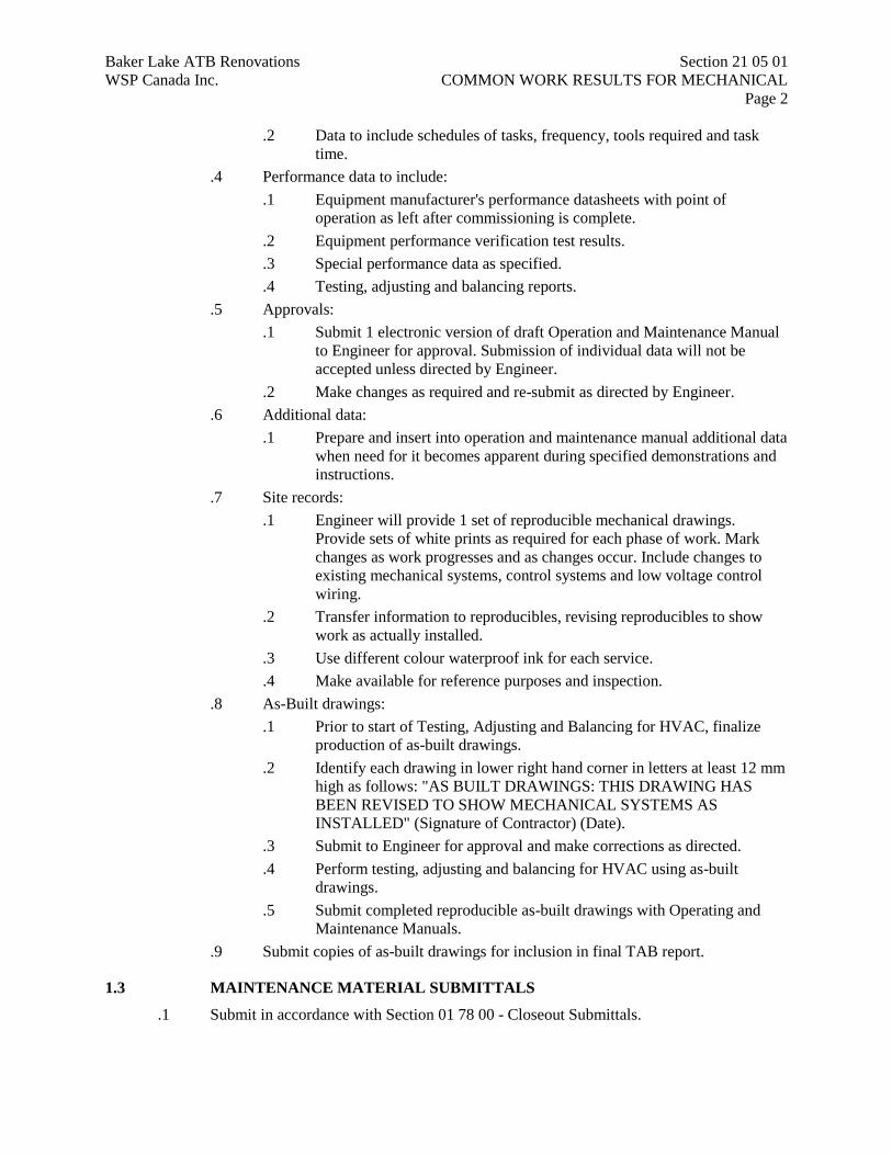
.2 Data to include schedules of tasks, frequency, tools required and task
time.
.4 Performance data to include:
.1 Equipment manufacturer's performance datasheets with point of
operation as left after commissioning is complete.
.2 Equipment performance verification test results.
.3 Special performance data as specified.
.4 Testing, adjusting and balancing reports.
.5 Approvals:
.1 Submit 1 electronic version of draft Operation and Maintenance Manual
to Engineer for approval. Submission of individual data will not be
accepted unless directed by Engineer.
.2 Make changes as required and re-submit as directed by Engineer.
.6 Additional data:
.1 Prepare and insert into operation and maintenance manual additional data
when need for it becomes apparent during specified demonstrations and
instructions.
.7 Site records:
.1 Engineer will provide 1 set of reproducible mechanical drawings.
Provide sets of white prints as required for each phase of work. Mark
changes as work progresses and as changes occur. Include changes to
existing mechanical systems, control systems and low voltage control
wiring.
.2 Transfer information to reproducibles, revising reproducibles to show
work as actually installed.
.3 Use different colour waterproof ink for each service.
.4 Make available for reference purposes and inspection.
.8 As-Built drawings:
.1 Prior to start of Testing, Adjusting and Balancing for HVAC, finalize
production of as-built drawings.
.2 Identify each drawing in lower right hand corner in letters at least 12 mm
high as follows: "AS BUILT DRAWINGS: THIS DRAWING HAS
BEEN REVISED TO SHOW MECHANICAL SYSTEMS AS
INSTALLED" (Signature of Contractor) (Date).
.3 Submit to Engineer for approval and make corrections as directed.
.4 Perform testing, adjusting and balancing for HVAC using as-built
drawings.
.5 Submit completed reproducible as-built drawings with Operating and
Maintenance Manuals.
.9 Submit copies of as-built drawings for inclusion in final TAB report.
1.3 MAINTENANCE MATERIAL SUBMITTALS
.1 Submit in accordance with Section 01 78 00 - Closeout Submittals.
Baker Lake ATB Renovations Section 21 05 01
WSP Canada Inc. COMMON WORK RESULTS FOR MECHANICAL
Page 3
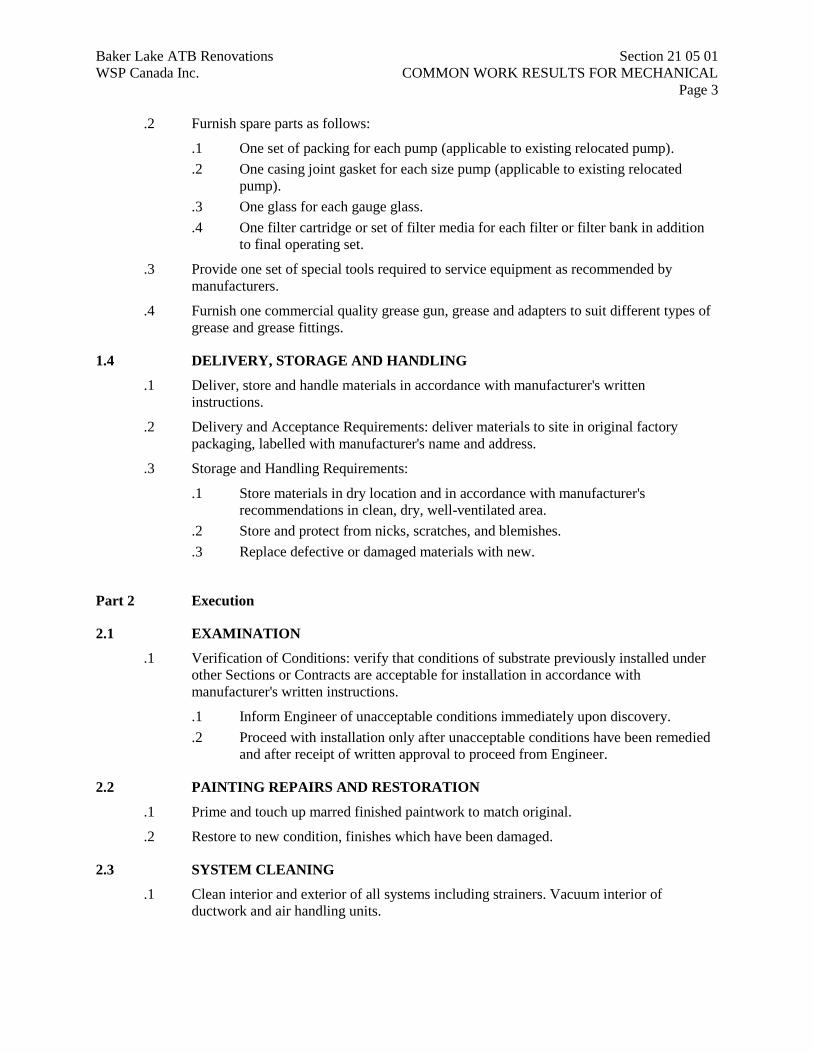
.2 Furnish spare parts as follows:
.1 One set of packing for each pump (applicable to existing relocated pump).
.2 One casing joint gasket for each size pump (applicable to existing relocated
pump).
.3 One glass for each gauge glass.
.4 One filter cartridge or set of filter media for each filter or filter bank in addition
to final operating set.
.3 Provide one set of special tools required to service equipment as recommended by
manufacturers.
.4 Furnish one commercial quality grease gun, grease and adapters to suit different types of
grease and grease fittings.
1.4 DELIVERY, STORAGE AND HANDLING
.1 Deliver, store and handle materials in accordance with manufacturer's written
instructions.
.2 Delivery and Acceptance Requirements: deliver materials to site in original factory
packaging, labelled with manufacturer's name and address.
.3 Storage and Handling Requirements:
.1 Store materials in dry location and in accordance with manufacturer's
recommendations in clean, dry, well-ventilated area.
.2 Store and protect from nicks, scratches, and blemishes.
.3 Replace defective or damaged materials with new.
Part 2 Execution
2.1 EXAMINATION
.1 Verification of Conditions: verify that conditions of substrate previously installed under
other Sections or Contracts are acceptable for installation in accordance with
manufacturer's written instructions.
.1 Inform Engineer of unacceptable conditions immediately upon discovery.
.2 Proceed with installation only after unacceptable conditions have been remedied
and after receipt of written approval to proceed from Engineer.
2.2 PAINTING REPAIRS AND RESTORATION
.1 Prime and touch up marred finished paintwork to match original.
.2 Restore to new condition, finishes which have been damaged.
2.3 SYSTEM CLEANING
.1 Clean interior and exterior of all systems including strainers. Vacuum interior of
ductwork and air handling units.
Baker Lake ATB Renovations Section 21 05 01
WSP Canada Inc. COMMON WORK RESULTS FOR MECHANICAL
Page 4
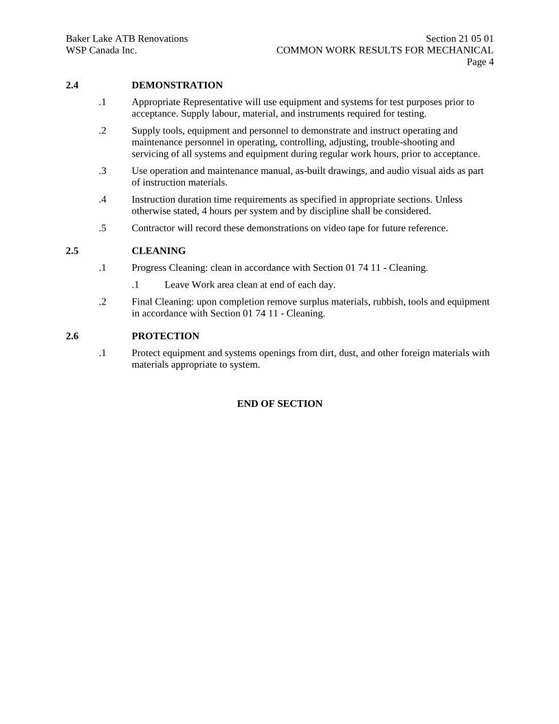
2.4 DEMONSTRATION
.1 Appropriate Representative will use equipment and systems for test purposes prior to
acceptance. Supply labour, material, and instruments required for testing.
.2 Supply tools, equipment and personnel to demonstrate and instruct operating and
maintenance personnel in operating, controlling, adjusting, trouble-shooting and
servicing of all systems and equipment during regular work hours, prior to acceptance.
.3 Use operation and maintenance manual, as-built drawings, and audio visual aids as part
of instruction materials.
.4 Instruction duration time requirements as specified in appropriate sections. Unless
otherwise stated, 4 hours per system and by discipline shall be considered.
.5 Contractor will record these demonstrations on video tape for future reference.
2.5 CLEANING
.1 Progress Cleaning: clean in accordance with Section 01 74 11 - Cleaning.
.1 Leave Work area clean at end of each day.
.2 Final Cleaning: upon completion remove surplus materials, rubbish, tools and equipment
in accordance with Section 01 74 11 - Cleaning.
2.6 PROTECTION
.1 Protect equipment and systems openings from dirt, dust, and other foreign materials with
materials appropriate to system.
END OF SECTION
Baker Lake ATB Renovations Section 22 42 01
WSP Canada Inc. PLUMBING SPECIALTIES AND ACCESSORIES
Page 1
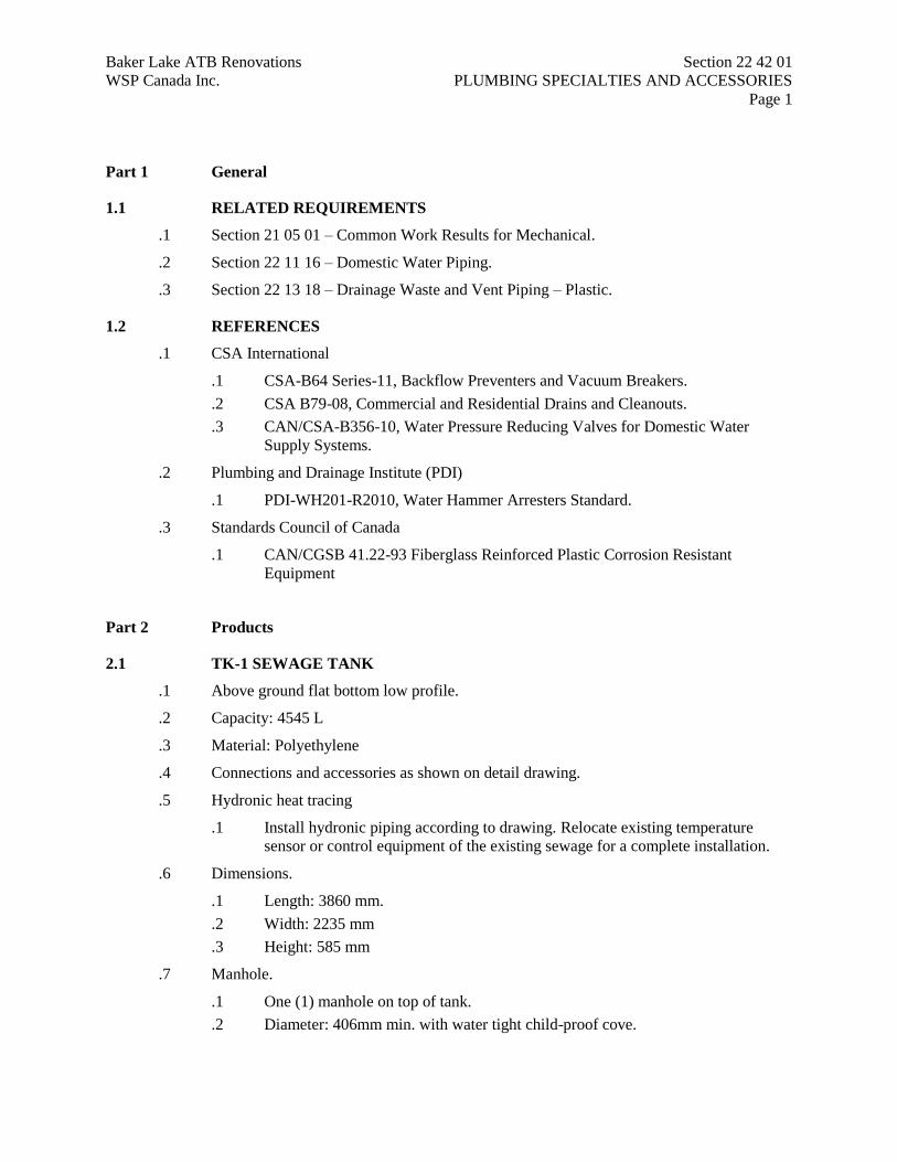
Part 1 General
1.1 RELATED REQUIREMENTS
.1 Section 21 05 01 – Common Work Results for Mechanical.
.2 Section 22 11 16 – Domestic Water Piping.
.3 Section 22 13 18 – Drainage Waste and Vent Piping – Plastic.
1.2 REFERENCES
.1 CSA International
.1 CSA-B64 Series-11, Backflow Preventers and Vacuum Breakers.
.2 CSA B79-08, Commercial and Residential Drains and Cleanouts.
.3 CAN/CSA-B356-10, Water Pressure Reducing Valves for Domestic Water
Supply Systems.
.2 Plumbing and Drainage Institute (PDI)
.1 PDI-WH201-R2010, Water Hammer Arresters Standard.
.3 Standards Council of Canada
.1 CAN/CGSB 41.22-93 Fiberglass Reinforced Plastic Corrosion Resistant
Equipment
Part 2 Products
2.1 TK-1 SEWAGE TANK
.1 Above ground flat bottom low profile.
.2 Capacity: 4545 L
.3 Material: Polyethylene
.4 Connections and accessories as shown on detail drawing.
.5 Hydronic heat tracing
.1 Install hydronic piping according to drawing. Relocate existing temperature
sensor or control equipment of the existing sewage for a complete installation.
.6 Dimensions.
.1 Length: 3860 mm.
.2 Width: 2235 mm
.3 Height: 585 mm
.7 Manhole.
.1 One (1) manhole on top of tank.
.2 Diameter: 406mm min. with water tight child-proof cove.
Baker Lake ATB Renovations Section 22 42 01
WSP Canada Inc. PLUMBING SPECIALTIES AND ACCESSORIES
Page 2
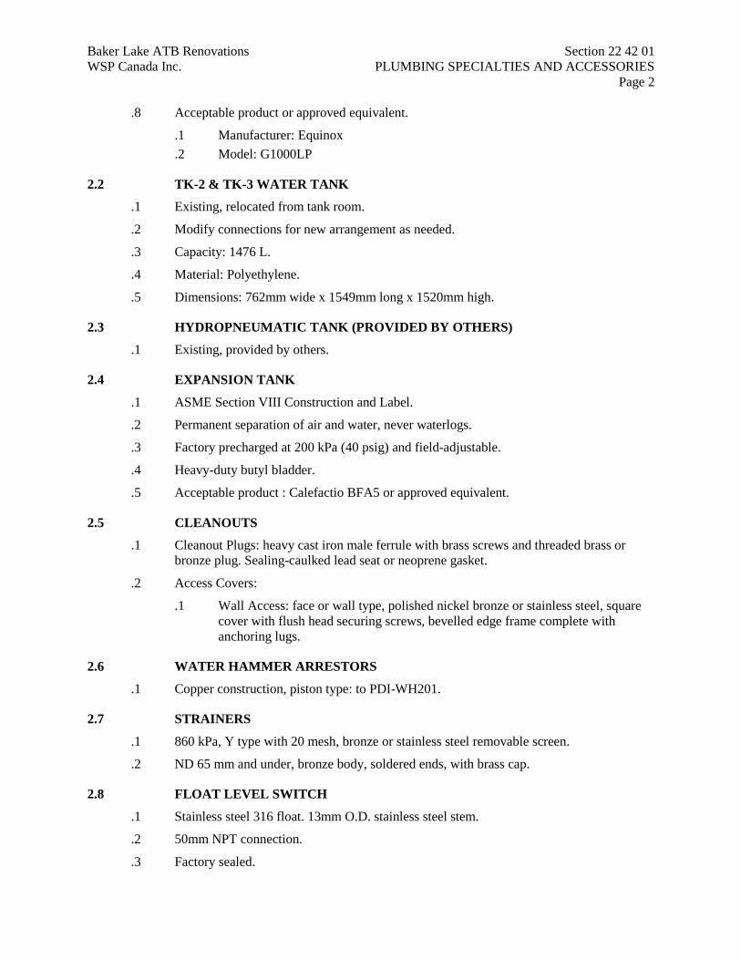
.8 Acceptable product or approved equivalent.
.1 Manufacturer: Equinox
.2 Model: G1000LP
2.2 TK-2 & TK-3 WATER TANK
.1 Existing, relocated from tank room.
.2 Modify connections for new arrangement as needed.
.3 Capacity: 1476 L.
.4 Material: Polyethylene.
.5 Dimensions: 762mm wide x 1549mm long x 1520mm high.
2.3 HYDROPNEUMATIC TANK (PROVIDED BY OTHERS)
.1 Existing, provided by others.
2.4 EXPANSION TANK
.1 ASME Section VIII Construction and Label.
.2 Permanent separation of air and water, never waterlogs.
.3 Factory precharged at 200 kPa (40 psig) and field-adjustable.
.4 Heavy-duty butyl bladder.
.5 Acceptable product : Calefactio BFA5 or approved equivalent.
2.5 CLEANOUTS
.1 Cleanout Plugs: heavy cast iron male ferrule with brass screws and threaded brass or
bronze plug. Sealing-caulked lead seat or neoprene gasket.
.2 Access Covers:
.1 Wall Access: face or wall type, polished nickel bronze or stainless steel, square
cover with flush head securing screws, bevelled edge frame complete with
anchoring lugs.
2.6 WATER HAMMER ARRESTORS
.1 Copper construction, piston type: to PDI-WH201.
2.7 STRAINERS
.1 860 kPa, Y type with 20 mesh, bronze or stainless steel removable screen.
.2 ND 65 mm and under, bronze body, soldered ends, with brass cap.
2.8 FLOAT LEVEL SWITCH
.1 Stainless steel 316 float. 13mm O.D. stainless steel stem.
.2 50mm NPT connection.
.3 Factory sealed.

Baker Lake ATB Renovations Section 22 42 01
WSP Canada Inc. PLUMBING SPECIALTIES AND ACCESSORIES
Page 3
.4 ULC listed.
.5 Electrical: 120V/1ph/60hz
.6 Detection
.1 Water tank: one float level detection.
.1 Ktech FS401E-1 or approved equivalent.
.2 Sewage tank: two float level detection.
.1 Ktech FS401E-2 or approved equivalent.
Part 3 Execution
3.1 EXAMINATION
.1 Verification of Conditions: verify that conditions of substrate previously installed under
other Sections or Contracts are acceptable for plumbing specialities and accessories
installation in accordance with manufacturer's written instructions.
.1 Inform Engineer of unacceptable conditions immediately upon discovery.
.2 Proceed with installation only after unacceptable conditions have been remedied
and after receipt of written approval to proceed from Engineer.
3.2 MANUFACTURER'S INSTRUCTIONS
.1 Compliance: comply with manufacturer's written recommendations or specifications,
including product technical bulletins, handling, storage and installation instructions, and
data sheet.
3.3 INSTALLATION
.1 Install in accordance with National Plumbing Code of Canada and local authority having
jurisdiction.
.2 Install in accordance with manufacturer's instructions and as specified.
3.4 SEWAGE TANK HEAT TRACING
.1 Install heat tracing according to drawings.
.2 Connect new sewage tank hydronic network to existing sewage tank network.
.3 Replicate hydronic heating existing control sequence of the actual sewage tank.
.4 Minimal sewage tank enclosure ambient temperature shall be set to 5°C.
3.5 CLEANOUTS
.1 Install cleanouts at base of soil and waste stacks, and rainwater leaders, at locations
required code, and as indicated.
.2 Bring cleanouts to wall or finished floor unless serviceable from below floor.
.3 Building drain cleanout and stack base cleanouts: line size to maximum ND 100mm.
Baker Lake ATB Renovations Section 22 42 01
WSP Canada Inc. PLUMBING SPECIALTIES AND ACCESSORIES
Page 4
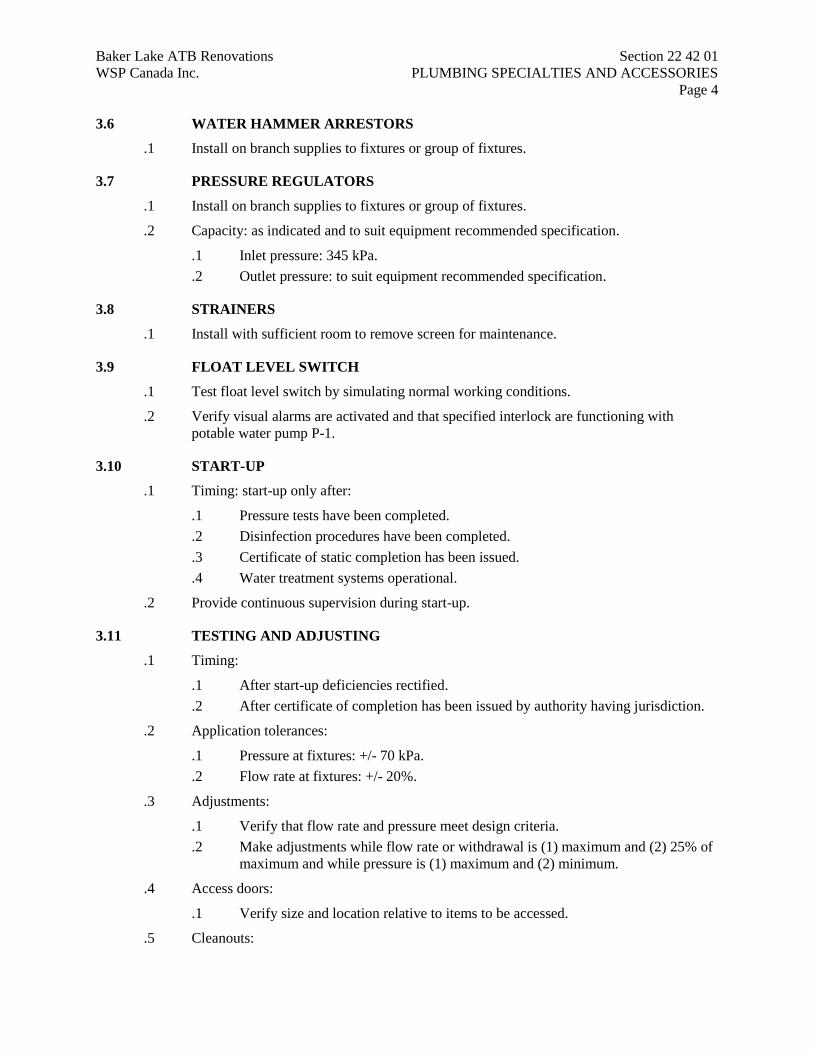
3.6 WATER HAMMER ARRESTORS
.1 Install on branch supplies to fixtures or group of fixtures.
3.7 PRESSURE REGULATORS
.1 Install on branch supplies to fixtures or group of fixtures.
.2 Capacity: as indicated and to suit equipment recommended specification.
.1 Inlet pressure: 345 kPa.
.2 Outlet pressure: to suit equipment recommended specification.
3.8 STRAINERS
.1 Install with sufficient room to remove screen for maintenance.
3.9 FLOAT LEVEL SWITCH
.1 Test float level switch by simulating normal working conditions.
.2 Verify visual alarms are activated and that specified interlock are functioning with
potable water pump P-1.
3.10 START-UP
.1 Timing: start-up only after:
.1 Pressure tests have been completed.
.2 Disinfection procedures have been completed.
.3 Certificate of static completion has been issued.
.4 Water treatment systems operational.
.2 Provide continuous supervision during start-up.
3.11 TESTING AND ADJUSTING
.1 Timing:
.1 After start-up deficiencies rectified.
.2 After certificate of completion has been issued by authority having jurisdiction.
.2 Application tolerances:
.1 Pressure at fixtures: +/- 70 kPa.
.2 Flow rate at fixtures: +/- 20%.
.3 Adjustments:
.1 Verify that flow rate and pressure meet design criteria.
.2 Make adjustments while flow rate or withdrawal is (1) maximum and (2) 25% of
maximum and while pressure is (1) maximum and (2) minimum.
.4 Access doors:
.1 Verify size and location relative to items to be accessed.
.5 Cleanouts:
Baker Lake ATB Renovations Section 22 42 01
WSP Canada Inc. PLUMBING SPECIALTIES AND ACCESSORIES
Page 5
.1 Verify covers are gas-tight, secure, yet readily removable.
.6 Water hammer arrestors:
.1 Verify proper installation of correct type of water hammer arrester.
.7 Pressure regulators, PRV assemblies:
.1 Adjust settings to suit locations, flow rates, pressure conditions.
.8 Strainers:
.1 Clean out repeatedly until clear.
.2 Verify accessibility for maintenance.
.3 Verify that cleanout does not leak.
3.12 PROTECTION
.1 Protect installed products and components from damage during construction.
.2 Repair damage to adjacent materials caused by plumbing specialties and accessories
installation.
END OF SECTION
Baker Lake ATB Renovations Section 23 05 00
WSP Canada Inc. SCOPE OF WORK MECHANICAL
Page 1
Part 1 Scope of work
1.1 GENERAL
.1 All new equipment and accessories, as needed, shall be supplied and installed by the
contractor for a complete installation.
.2 Execute work as specified in the scope of work mechanical and according to drawings.
.3 Dispose of removed equipment at appropriate facilities.
.4 Verify systems performance.
.5 Provide adequate training for operations and maintenance.
1.2 DEMOLITION OF EXISTING
.1 Remove ground floor plumbing appliances, accessories and related supply and sewage
piping. Remove any equipment as needed for washrooms and janitor closet demolition.
.1 Male W/C (1-12)
.1 One (1) toilet.
.2 One (1) sink.
.3 One (1) paper towel distributor.
.4 One (1) hand towel distributor.
.5 Exhaust fan and ducting.
.6 Accessories.
.2 Female W/C (1-14)
.1 One (1) toilet.
.2 One (1) sink.
.3 One (1) paper towel distributor.
.4 One (1) hand towel distributor.
.5 Exhaust fan and ducting.
.6 Accessories.
.3 Janitor closet (1-13)
.1 One (1) mop sink.
.2 Abandoned plumbing.
.3 Accessories.
.2 Mechanical tank room (1-16)
.1 Remove two (2) plastic domestic water storage tanks (individual capacity 1476L)
and associated piping.
.2 Relocate two (2) plastic domestic water storage tanks (individual capacity
1476L). Remove associated piping. Modify piping connections as needed for the
new arrangement.
.3 Remove wood housekeeping pad underneath existing water tanks.
Baker Lake ATB Renovations Section 23 05 00
WSP Canada Inc. SCOPE OF WORK MECHANICAL
Page 2
.4 Relocate one (1) domestic water pump (1/2 hp), wall support and one (1)
hydropneumatic tank.
.5 Relocate one (1) unit heater control wiring.
.6 Cap exterior wall openings according to architectural specifications.
.7 Remove one (1) decommissioned above ground steel sewage tank (approximate
dimensions are 3658mm x diam. 1829mm) and associated piping.
.3 Ventilation
.1 Clean all building ducting.
.2 Remove grille and ducting for new office ducting.
.3 AHU
.1 Remove AHU, hydronic heat exchanger, mixing valve and associated
corroded piping.
.2 Remove existing control probes, control panel and wiring.
.3 Remove outside air fan.
.4 Fuel system
.1 Remove fuel tank, support, pipe supports, accessories and associated piping, as
indicated.
.5 Sewage tank
.1 Remove temperature sensor and other equipment relating to the hydronic heat
tracing for relocation.
1.3 NEW ARRANGEMENT
.1 Male W/C
.1 Install one (1) new exhaust fan common to Male and female’s WC in suspended
ceilings, grille, exhaust vent hood, ceiling grilles (4 total) and ducting to exterior.
.2 Install one (1) new toilet.
.3 Install one (1) new urinal.
.4 Install two (1) wall hung sink.
.5 Install cold and hot water piping supply to appliances.
.6 Install vent piping.
.7 Install sanitary piping from appliances to new sewage tank. Insulate exterior
piping and seal floor penetration according to architectural specifications.
.2 Female W/C
.1 Install two (2) toilets.
.2 Install two (1) wall hung sink.
.3 Install cold and hot water supply to appliances.
.4 Install vent piping.
.5 Install sanitary piping from appliances to new sewage tank. Insulate exterior
piping and seal floor penetration according to architectural specifications.
.3 Water storage room (1-8)
Baker Lake ATB Renovations Section 23 05 00
WSP Canada Inc. SCOPE OF WORK MECHANICAL
Page 3
.1 Install two (2) existing water tanks, one (1) existing water pump (provided with
low and high pressure switch) with wall support, one (1) existing
hydropneumatic tank, one (1) low level switch, one (1) new water heater, one (1)
new expansion tank, fill pipe and overflow piping.
.2 Install cold and hot water piping to appliances (ground floor and upper floor) and
supports, as needed.
.4 Janitor storage (1-10)
.1 Install one (1) new janitor sink.
.2 Install cold and hot water supply to appliances as needed.
.3 Install vent piping to new vent piping.
.4 Install sanitary piping from appliances to new sewage tank. Insulate exterior
piping and seal floor penetration according to architectural specifications.
.5 Airline office (1-15)
.1 Install fin clamps on existing hydronic baseboard heating system.
.2 Install vent piping up to the roof.
.3 Install electrical arctic vent.
.6 AHU
.1 Install one new AHU, new hydronic heat exchanger, new mixing valve and new
piping.
.2 Install control probes, control panel and wiring.
.3 Install ducting and connect AHU to supply air and outside air ducting.
.4 Balance ventilation system.
.7 Sewage tank
.1 Install one (1) new heat traced (hydronic) exterior sewage tank located
underneath new water tank room, enclosed in plywood.
.2 Install control temperature sensor and other equipment for a complete
installation.
.3 Connect new sewage tank hydronic network to existing sewage tank network.
.4 Replicate hydronic heating existing control sequence of the actual sewage tank.
.5 Install pump-out connection, supports, two (2) high level switch and accessories.
.6 Install sanitary insulated piping from appliances (ground floor and upper floor) to
new sewage tank, hydronic heat tracing, supports and accessories.
.8 CARS
.1 Install hydronic baseboard fin clamps (approximately 2.5m).
.2 Restore supply ducting grilles at CARS windows (remove tape and clean).
.3 Install toilet vent from 1st floor ceiling to roof.
.9 Fuel system
.1 Install new gravel pad.
.2 Install one (1) fuel tank (provided by others) on new gravel pad.
.3 Install access platform or access stairs for filling operations as required.

Baker Lake ATB Renovations Section 23 05 00
WSP Canada Inc. SCOPE OF WORK MECHANICAL
Page 4
.4 Install new piping, valves, fuel pumps (2) and other accessories as indicated.
.5 Install suspended pipe supports attached to building structure.
.6 Install pipe support for pipe connections to fuel tank. Proper measures shall be
taken to ensure that no constraints are applied to the tank connections.
.7 Start-up the two oil burners with new fuel system and provide start-up report.
.10 2nd floor washroom
.1 Install sanitary piping from 2nd floor sanitary piping in technical space to new
sewage tank.
END OF SECTION
Baker Lake ATB Renovations Section 23 05 13
WSP Canada Inc. COMMON MOTOR REQUIREMENTS FOR HVAC
EQUIPMENT
Page 1
Part 1 General
1.1 SUMMARY
.1 Section Includes:
.1 Electrical motors, drives and guards for mechanical equipment and systems.
.2 Supplier and installer responsibility indicated in Motor, Control and Equipment
Schedule on electrical drawings and related mechanical responsibility is
indicated on Mechanical Equipment Schedule on mechanical drawings.
.2 Related Requirements
.1 Section 23 34 00 – HVAC Fans.
1.2 REFERENCES
.1 American Society of Heating, Refrigeration and Air-Conditioning Engineers (ASHRAE)
.1 ASHRAE 90.1-01, Energy Standard for Buildings Except Low-Rise Residential
Buildings (IESNA cosponsored; ANSI approved; Continuous Maintenance
Standard).
.2 Electrical Equipment Manufacturers' Association Council (EEMAC)
Part 2 Products
2.1 GENERAL
.1 Motors: high efficiency, in accordance with Qulliq Energy Corporation (QEC) standards
and to ASHRAE 90.1.
2.2 MOTORS
.1 Provide motors for mechanical equipment as specified.
.2 Motors under 373 W (1/2 HP) : speed as indicated, continuous duty, built-in overload
protection, resilient mount, single phase, 120 V, unless otherwise specified or indicated.
.3 Motors 373 W (1/2 HP) and larger: EEMAC Class B, squirrel cage induction, speed as
indicated, continuous duty, drip proof, ball bearing, maximum temperature rise 40
degrees C, 3 phase, 208 V, unless otherwise indicated.
2.3 BELT DRIVES
.1 Fit reinforced belts in sheave matched to drive. Multiple belts to be matched sets.
.2 Use cast iron or steel sheaves secured to shafts with removable keys unless otherwise
indicated.
.3 For motors under 7.5 kW (10 HP) : standard adjustable pitch drive sheaves, having plus
or minus 10% range. Use mid-position of range for specified r/min.
Baker Lake ATB Renovations Section 23 05 13
WSP Canada Inc. COMMON MOTOR REQUIREMENTS FOR HVAC
EQUIPMENT
Page 2
.4 Correct size of sheave determined during commissioning.
.5 Minimum drive rating: 1.5 times nameplate rating on motor. Keep overhung loads within
manufacturer's design requirements on prime mover shafts.
.6 Motor slide rail adjustment plates to allow for centre line adjustment.
.7 Supply one set of spare belts for each set installed in accordance with Section 01 78 00 -
Closeout Submittals.
2.4 DRIVE GUARDS
.1 Provide guards for unprotected drives.
.2 Guards for belt drives;
.1 Expanded metal screen welded to steel frame.
.2 Minimum 1.2 mm thick sheet metal tops and bottoms.
.3 38 mm diameter holes on both shaft centres for insertion of tachometer.
.4 Removable for servicing.
.3 Provide means to permit lubrication and use of test instruments with guards in place.
.4 Install belt guards to allow movement of motors for adjusting belt tension.
.1 "U" shaped, minimum 1.6 mm thick galvanized mild steel.
.2 Securely fasten in place.
.3 Removable for servicing.
.5 Flexible coupling guard
.1 "U" shaped, minimum 1.6 mm thick galvanized mild steel.
.2 Securely fasten in place.
.3 Removable for servicing.
.6 Unprotected fan inlets or outlets:
.1 Wire or expanded metal screen, galvanized, 19 mm mesh.
.2 Net free area of guard: not less than 80% of fan openings.
.3 Securely fasten in place.
.4 Removable for servicing.
Baker Lake ATB Renovations Section 23 05 13
WSP Canada Inc. COMMON MOTOR REQUIREMENTS FOR HVAC
EQUIPMENT
Page 3
Part 3 Execution
3.1 MANUFACTURER'S INSTRUCTIONS
.1 Compliance: comply with manufacturer's written recommendations or specifications,
including product technical bulletins, handling, storage and installation instructions, and
datasheet.
3.2 INSTALLATION
.1 Fasten securely in place.
.2 Make removable for servicing, easily returned into, and positively in position.
END OF SECTION