Plain and thread plug and ring gage blanks requesttheapplicationofthecertificationplanbytheBureauof...
64
Transcript of Plain and thread plug and ring gage blanks requesttheapplicationofthecertificationplanbytheBureauof...


U. S. DEPARTMENT OF COMMERCEBUREAU OF STANDARDS
PLAIN AND THREAD
PLUG AND RING GAGE BLANKS
RECOMMENDED COMMERCIAL STANDARD
as adopted by
THE AMERICAN GAGE DESIGN COMMITTEE
MISCELLANEOUS PUBLICATION, BUREAU OF STANDARDS, No. 100

U. S. DEPARTMENT OF COMMERCER. P. LAMONT, Secretary
BUREAU OF STANDARDSGEORGE K. BURGESS, Director
MISCELLANEOUS PUBLICATION No. 100
PLAIN AND THREADPLUG AND RING GAGE BLANKS
RECOMMENDED COMMERCIAL STANDARD
as adopted by
THE AMERICAN GAGE DESIGN COMMITTEE
UNITED STATES
GOVERNMENT PRINTING OFFICE
WASHINGTON : 1930
For sale by the Superintendent of Documents, Washington, D. C, Price 15 cents
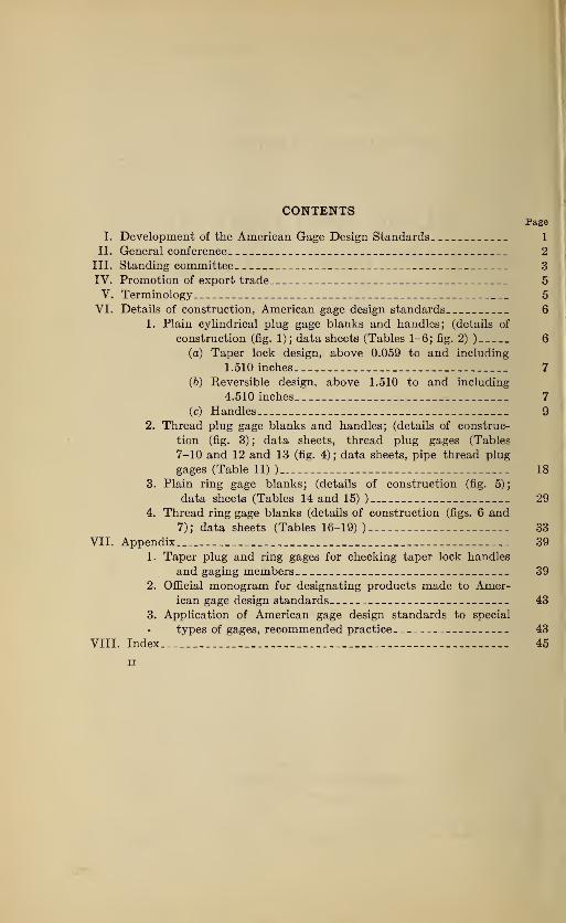
CONTENTSPage
I. Development of the American Gage Design Standards 1
II. General conference 2
III. Standing committee 3
IV. Promotion of export trade 5
V. Terminology 5
VI. Details of construction, American gage design standards 6
1. Plain cylindrical plug gage blanks and handles; (details of
construction (fig. 1) ; data sheets (Tables 1-6; fig. 2)) 6
(a) Taper lock design, above 0.059 to and including
1.510 inches 7
(6) Reversible design, above 1.510 to and including
4.510 inches 7
(c) Handles 9
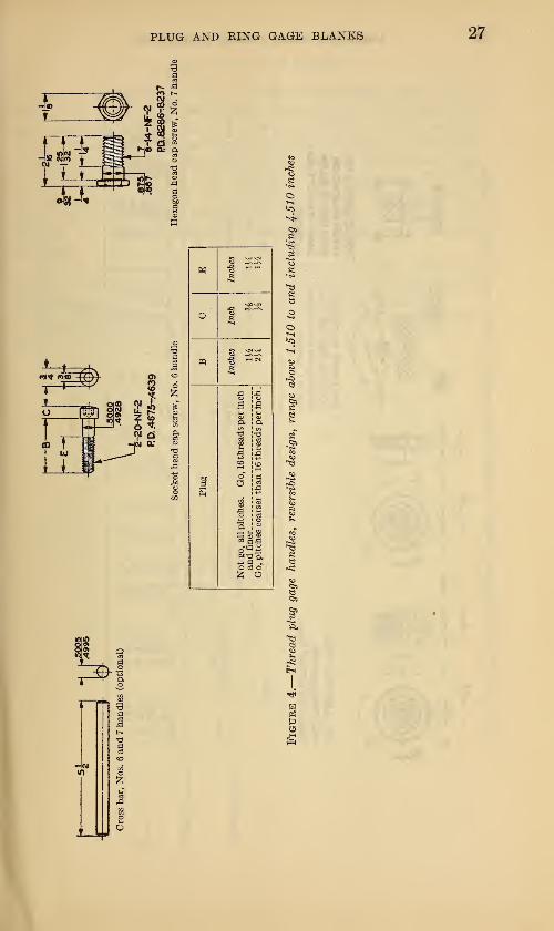
2. Thread plug gage blanks and handles; (details of construc-
tion (fig. 3); data sheets, thread plug gages (Tables
7-10 and 12 and 13 (fig. 4); data sheets, pipe thread plug
gages (Table 11) ) 18
3. Plain ring gage blanks; (details of construction (fig. 5);
data sheets (Tables 14 and 15)) 29
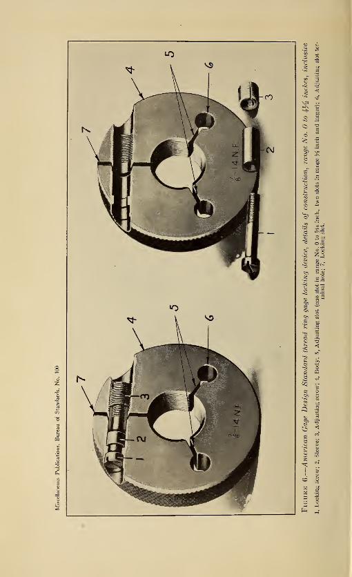
4. Thread ring gage blanks (details of construction (figs. 6 and
7); data sheets (Tables 16-19) ) 33
VII. Appendix 39
1. Taper plug and ring gages for checking taper lock handles
and gaging members 39
2. Official monogram for designating products made to Amer-ican gage design standards 43
3. Application of American gage design standards to special
types of gages, recommended practice 43
VIII. Index 45
ii
PLAIN AND THREAD PLUG AND RING GAGE BLANKS
RECOMMENDED COMMERCIAL STANDARD AS ADOPTED BY THEAMERICAN GAGE DESIGN COMMITTEE
[REPORT OF THE AMERICAN GAGE DESIGN COMMITTEE]
I. DEVELOPMENT OF THE AMERICAN GAGE DESIGNSTANDARDS
The American Gage Design Committee was formed in December,
1926, to consolidate for the benefit of industry at large the independent
efforts which were already in progress on the part of a number of large
industrial concerns, representatives of United States Governmentdepartments, and several of the leading gage manufacturers to simplify
gaging practice through the adoption of standard designs for gage
blanks and component parts. The designs developed by the Ameri-
can Gage Design Committee are now available to everyone and will
minimize the necessity for the manufacture of special gages of the
simpler types. The committee was given full support and recognition
by engineering societies, the American Standards Association, the
Bureau of Standards, the War and Navy Departments, and the
National Screw Thread Commission. It should be pointed out,
however, that the major work of the committee was contributed byindustry itself, many of the country's largest industrial units in
widely diversified fields being represented by active membership onthe committee. Joint meetings were held with the National Screw
Thread Commission throughout 1927 and 1928. Rapid progress wasmade in these meetings, and formal design standards were completed
and adopted for plain plug and ring, and thread plug and ring gages
of all sizes above 0.059 to and including 4% inches diameter.
The meetings of the committee were open, and ideas and suggestions
from all branches of industry were welcomed and given careful con-
sideration, it being the earnest endeavor of the committee to crystal-
lize the best design and construction of gage blanks, handles, andcomponent parts for plain and thread gages. No attempt has been
made to set gage tolerances or fits, the work being confined solely to
selection of the best possible designs for gage blanks ; but the work onfits and tolerances of the National Screw Thread Commission and of
the Sectional Committee on the Standardization of Plain Limit
Gages for General Engineering Work is available for use in connection
with gages made to American Gage Design Standards.
1
2 AMERICAN GAGE DESIGN COMMITTEE
The fullest cooperation was extended by all, proprietary patent
rights being waived by individual gage manufacturers for the general
benefit of industry.
In promulgating the new standards, the committee has not intended
to obsolete existing stocks of gages in the hands of manufacturers or
users; rather, it has been its intention to provide a standard which
could be gradually adopted through replacement of existing stocks.
Representing the best ideas of industry at large, including gage makersand gage users, the American Gage Design Standards should havewhole-hearted support and be accepted and used by gage purchasers,
and should render obsolete the wasteful and costly practice of requi-
sitioning gages to individual design standards, which has existed in
many cases heretofore. Tool supervisors and standards departments
of large industrial concerns are particularly urged to adopt, as soon as
practicable, the American Gage Design Standards as a substitute for
any individual standards which may now be employed. The result
will inevitably be the elimination of confusion in gage departments,
and advancement in the direction of economy and quality of product.
The committee's efforts to make available in every instance the best
possible design of gage blank was materially furthered by the generous
action of the gage manufacturers represented on the committee, all
of whom offered without reservation to dedicate to public use their
proprietary patent rights on any gage construction, the utilization of
which might be desired by the committee. The committee desires to
make formal recognition in this report of the specific action of the
Pratt & Whitney Co., of Hartford, Conn., and the Taft-Peirce Manu-facturing Co., of Woonsocket, R. I., in contributing, respectively,
their patented trilock plug gage design and patented single-unit
thread-ring gage locking device to public use, as a part of this stand-
ardization program.
The American Gage Design Standards are detailed by description,
line drawings, and dimensional tables in the pages that follow.
II. GENERAL CONFERENCE
The sessions of the American Gage Design Committee held Octo-
ber 12 and 13, 1928, in New Haven, Conn., assumed the functions
of the general conference. Practically all of the leading producers
and users had been invited, and the work of the committee was es-
sentially complete.
The general conference formally adopted the report of the American
Gage Design Committee as a commercial standard and voted to
request the application of the certification plan by the Bureau of
Standards.
The conference set the effective date for new production as July 1,
1929, and for clearance of existing stocks as not later than January 1,
1931.
PLUG AND RING GAGE BLANKS 3
It was the consensus of opinion that the standard should be regu-
larly considered for revision every six months in order that it might
be kept abreast with current practices and progress in the art.
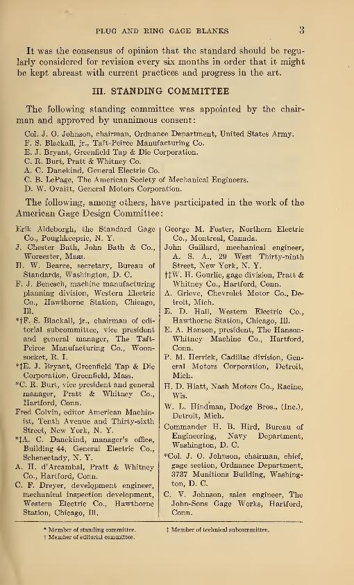
III. STANDING COMMITTEE
The following standing committee was appointed by the chair-
man and approved by unanimous consent:
Col. J. O. Johnson, chairman, Ordnance Department, United States Army.F. S. Blackall, jr., Taft-Peirce Manufacturing Co.
E. J. Bryant, Greenfield Tap & Die Corporation.
C. R. Burt, Pratt & Whitney Co.
A. C. Danekind, General Electric Co.
C. B. LePage, The American Society of Mechanical Engineers.
D. W. Ovaitt, General Motors Corporation.
The following, among others, have participated in the work of the
American Gage Design Committee:
Erik Aldeborgh, the Standard GageCo., Poughkeepsie, N. Y.
J. Chester Bath, John Bath & Co.,
Worcester, Mass.
H. W. Bearce, secretary, Bureau of
Standards, Washington, D. C.
F. J. Benesch, machine manufacturing
planning division, Western Electric
Co., Hawthorne Station, Chicago,
IU.
*fF. S. Blackall, jr., chairman of edi-
torial subcommittee, vice president
and general manager, The Taft-
Peirce Manufacturing Co., Woon-socket, R. I.
*JE. J. Bryant, Greenfield Tap & Die
Corporation, Greenfield, Mass.
*C. R. Burt, vice president and general
manager, Pratt & Whitney Co.,
Hartford, Conn.
Fred Colvin, editor American Machin-ist, Tenth Avenue and Thirty-sixth
Street, New York, N. Y.
*JA. C. Danekind, manager's office,
Building 44, General Electric Co.,
Schenectady, N. Y.
A. H. d'Arcambal, Pratt & WhitneyCo., Hartford, Conn.
C. F. Dreyer, development engineer,
mechanical inspection development,
Western Electric Co., HawthorneStation, Chicago, 111.
George M. Foster, Northern Electric
Co., Montreal, Canada.John Gaillard, mechanical engineer,
A. S. A., 29 West Thirty-ninth
Street, New York, N. Y.
tfW. H. Gourlie, gage division, Pratt &Whitney Co., Hartford, Conn.
A. Grieve, Chevrolet Motor Co., De-troit, Mich.
E. D. Hall, Western Electric Co.,
Hawthorne Station, Chicago, 111.
E. A. Hanson, president, The Hanson-Whitney Machine Co., Hartford,
Conn.
P. M. Herrick, Cadillac division, Gen-eral Motors Corporation, Detroit,
Mich.
H. D. Hiatt, Nash Motors Co., Racine,
Wis.
W. L. Hindman, Dodge Bros., (Inc.),
Detroit, Mich.
Commander H. B. Hird, Bureau of
Engineering, Navy Department,
Washington, D. C.
*Col. J. O. Johnson, chairman, chief,
gage section, Ordnance Department,
3737 Munitions Building, Washing-ton, D. C.
C. V. Johnson, sales engineer, TheJohn-Sons Gage Works, Hartford,
Conn.
* Member of standing committee,
t Member of editorial committee.X Member of technical subcommittee.
4 AMERICAN GAGE DESIGN COMMITTEE
JH. S. Kartsher, 3211 Sycamore Road,
Cleveland Heights, Ohio.
*C. B. LePage, assistant secretary,
A. S. M. E., 29 West Thirty-ninth
Street, New York, N. Y.
JH. B. Lewis, Brown & Sharpe Manu-facturing Co., Providence, R. I.
A. M. Lord, Taylor Instrument Cos.,
Rochester, N. Y.
JL. M. McPharlin, Pierce-Arrow MotorCar Co., Buffalo, N. Y.
J P. V. Miller, manager, small tool
department, The Taft-Peirce Manu-facturing Co., Woonsocket, R. I.
C. H. Moen, Muncie Products Co.,
Muncie, Ind.
W. C. Mueller, assistant superintendent
of manufacturing planning, Western
Electric Co., Hawthorne Station,
Chicago, 111.
R. S. Newton, the New York Air
Brake Co., Watertown, N. Y.
W. J. Outcalt, standards section, Gen-
eral Motors Corporation, Detroit,
Mich.
*JD. W. Ovaitt, chairman of technical
subcommittee, General Motors Cor-
poration, c/o Buick Motor Co., Flint,
Mich.
C. J. Oxford, chief engineer, National
Twist DriU & Tool Co., Detroit,
Mich.
Lieut. Col. E. C. Peck, Room 305,
Lake Erie Bank Building, 1612 Eu-clid Avenue, Cleveland, Ohio.
Louis E. Peck, general manager, the
Threadwell Tool Co., Greenfield,
Mass.
Charles M. Pond, manager, small tool
and gage division, Pratt & WhitneyCo., Hartford, Conn.
C. H. Reynolds, The Sheffield Machine& Tool Co., Dayton, Ohio.
P. D. Ritchey, the Standard Gage Co.,
Poughkeepsie, N. Y.
C. E. Rundorff, research department,
Buick Motor Co., Flint, Mich.
JA. W. Schoof, gage development andstandards department, Western Elec-
tric Co., Hawthorne Station, Chi-
cago, 111.
A. J. Schwartz, United States NavalGun Factory, Navy Yard, Washing-ton, D. C.
J. A. Siegel, Packard Motor Car Co.,
Detroit, Mich.
O. J. Snider, Cadillac Motor Car Co.,
Detroit, Mich.
H. B. Stringer, Winter Bros. Co., Wren-tham, Mass.
H. L. Van Keuren, The Van KeurenCo., 12 Copeland Street, Water-
town, Boston, Mass.
$C. E. Watterson, president, The Shef-
field Machine & Tool Co., Dayton,Ohio.
JW. H. Weingar, 88 Maplewood Ave-
nue, West Hartford, Conn.
K. D. Williams, Bureau of Engineer-
ing, Room 2326, Navy Department,
Washington, D. C.
Charles E. Winter, Winter Bros. Co.,
Wrentham, Mass.
George R. Worner, Taylor Instrument
Cos., Rochester, N. Y.
* Member of standing committee,
t Member of editorial committee.t Member of technical subcommittee.
PLUG AND RING GAGE BLANKS 5
IV. PROMOTION OF EXPORT TRADE
The question of promoting export trade on the basis of these
standards was left to the discretion of the standing committee.
V. TERMINOLOGY
The following glossary is intended to clarify the meaning of certain
technical terms employed in this report. The definitions are not
intended to be general; rather they are specific as to their applica-
tion to the American Gage Design Standards.
1. American Gage Design Standard.—The caption "American GageDesign Standard " has been adopted to designate gages made to the
design specifications promulgated by the American Gage Design
Committee.
2. A plain cylindrical plug gage is a complete unthreaded internal
gage of single or double ended type for the size control of holes. It
consists of handle and gaging member or members, with suitable
locking means.
3. A progressive cylindrical plug gage is a complete unthreaded in-
ternal gage consisting of handle and gaging member in which the "go "
and "not go" gaging sections are combined in a single unit secured
to one end of the handle.
4. A thread plug gage is a complete internal thread gage of either
single or double ended type, comprising handle and threaded gaging
member or members, with suitable locking means.
5. The gaging member is that integral unit of a plug gage which is
accurately finished to size and is employed for size control of the work.
In taper lock gages, the gaging member consists of a shank and a
gaging section.
6. The gaging section is that portion of the gage which comes into
physical contact with the work. In the plug range above 1.510 to
and including 4.510 inches, the gaging section is identical with the
gaging member.
7. The shank (applied to taper lock gages only) is that portion of
the gaging member which is employed for fixing the gaging memberto the handle.
8. The term utaper lock" designates that construction in which the
gaging member has a taper shank, which is forced into a taper hole
in the handle. This design is standard for plug gages in the range
above 0.059 inch to and including 1.510 inches, is optional for plain
cylindrical and thread plug gages in the range above 1.510 inches to
and including 2.510 inches, and is standard for pipe-thread plug gages
up to and including 2-inch nominal pipe size.
9. A reversible plug gage is a plain cylindrical or thread plug gage,
in which three wedge-shaped locking prongs on the handle are forced
into corresponding locking grooves in the gaging member by means of
6 AMERICAN GAGE DESIGN COMMITTEE
a single through screw thus providing a self-centering support with a
positive lock. This design is standard for all plug gages in the ranges
above 1.510 to and including 4.510 inches, with the exception of pipe
thread plug gages, for which it is standard in the ranges above 2.510
to and including 4.510 inches.
10. Lightening holes are unfinished drilled holes provided in the
heavier sizes of gaging members for the sole purpose of reducing the
weight of the gage.
11. The handle is that portion of a plug gage which is employed as
supporting means for the gaging member or members.
12. The drift hole or drift slot is a small hole or slot provided in the
side of a taper lock gage handle near the "go" end through which a
pin or drift may be inserted for the purpose of ejecting the gaging
member from the handle.
13. A plain ring gage is an unthreaded external gage employed for
the size control of external diameters. In the smaller sizes it consists
of a gage body into which is pressed a bushing, the latter being ac-
curately finished to size for gaging purposes.
14. A thread ring gage is an external thread gage employed for the
size control of threaded work, means of adjustment being provided
integral with the gage body.
15. The flange is that external portion of a large ring gage which is
reduced in section for the purpose of lightening the gage.
16. The hub is the mid-section of a flanged ring gage. It determines
the length of the gaging section.
17. The thread ring gage locking device is a means of expanding and
contracting the thread ring gage during the manufacturing or resizing
processes. It also provides an effectual lock. It comprises an adjust-
ing screw, a locking screw, and a sleeve. For detailed description and
illustration see page 33.
18. Adjusting slots are radial slots provided in thread ring gages in
order to facilitate expansion and contraction of gage size by means of
the adjusting device. An adjusting slot always terminates in an
adjusting slot terminal hole.
19. The locking slot is that slot which passes entirely through the
wall of a thread ring gage. In conjunction with the thread ring gage
locking device, it permits expansion and contraction of gage size.
VI. DETAILS OF CONSTRUCTION, AMERICAN GAGE DESIGNSTANDARDS
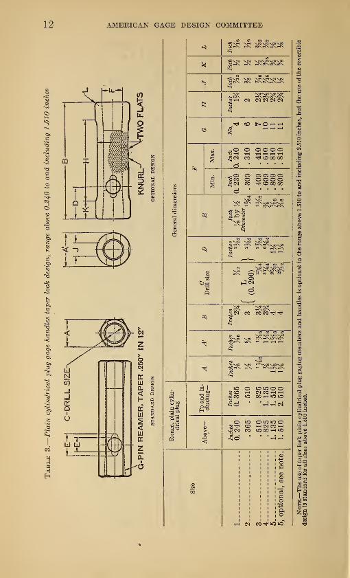
1. PLAIN CYLINDRICAL PLUG GAGE BLANKS AND HANDLES
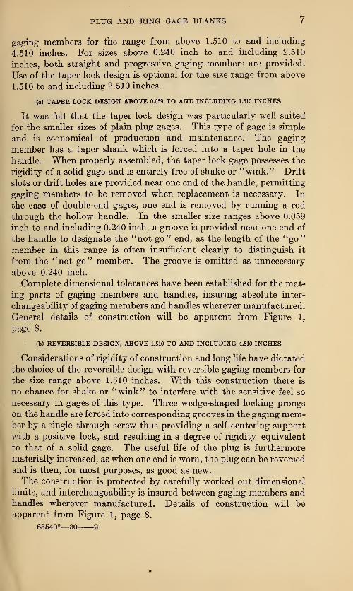
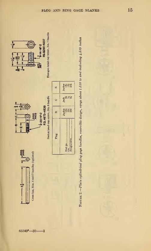
Two separate designs have been adopted for plain cylindrical
plug gages—the taper lock design for the range from 0.059 to and
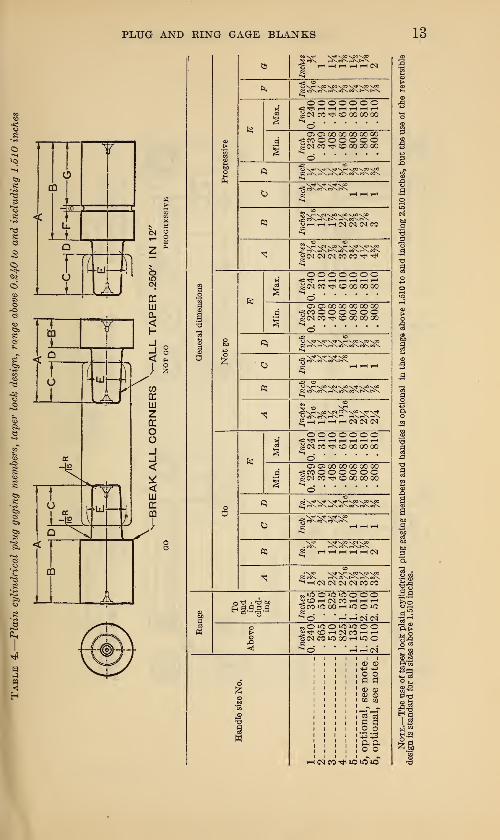
including 1.510 inches, and the reversible design with reversible
PLUG AND KING GAGE BLANKS 7
gaging members for the range from above 1.510 to and including
4.510 inches. For sizes above 0.240 inch to and including 2.510
inches, both straight and progressive gaging members are provided.
Use of the taper lock design is optional for the size range from above
1.510 to and including 2.510 inches.
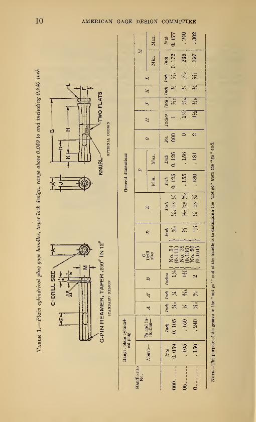
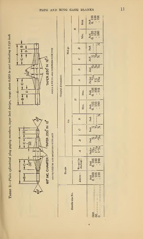
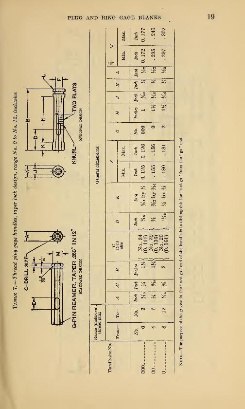
(a) TAPER LOCK DESIGN ABOVE 0.059 TO AND INCLUDING 1.510 INCHES
It was felt that the taper lock design was particularly well suited
for the smaller sizes of plain plug gages. This type of gage is simple
and is economical of production and maintenance. The gaging
member has a taper shank which is forced into a taper hole in the
handle. When properly assembled, the taper lock gage possesses the
rigidity of a solid gage and is entirely free of shake or "wink." Drift
slots or drift holes are provided near one end of the handle, permitting
gaging members to be removed when replacement is necessary. In
the case of double-end gages, one end is removed by running a rod
through the hollow handle. In the smaller size ranges above 0.059
inch to and including 0.240 inch, a groove is provided near one end of
the handle to designate the "not go" end, as the length of the "go"member in this range is often insufficient clearly to distinguish it
from the "not go" member. The groove is omitted as unnecessary
above 0.240 inch.
Complete dimensional tolerances have been established for the mat-
ing parts of gaging members and handles, insuring absolute inter-
changeability of gaging members and handles wherever manufactured.
General details of construction will be apparent from Figure 1,
page 8.
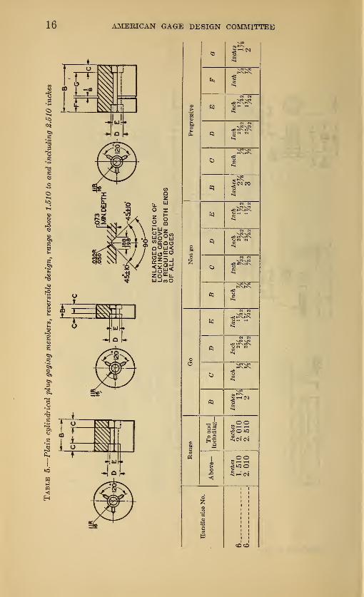
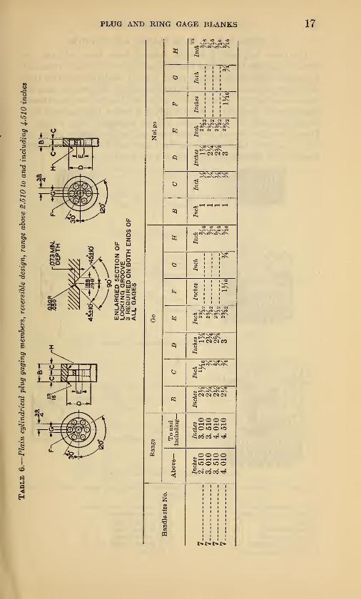
(b) REVERSIBLE DESIGN, ABOVE 1.510 TO AND INCLUDING 4.510 INCHES
Considerations of rigidity of construction and long life have dictated
the choice of the reversible design with reversible gaging members for
the size range above 1.510 inches. With this construction there is
no chance for shake or "wink" to interfere with the sensitive feel so
necessary in gages of this type. Three wedge-shaped locking prongs
on the handle are forced into corresponding grooves in the gaging mem-ber by a single through screw thus providing a self-centering support
with a positive lock, and resulting in a degree of rigidity equivalent
to that of a solid gage. The useful life of the plug is furthermore
materially increased, as when one end is worn, the plug can be reversed
and is then, for most purposes, as good as new.
The construction is protected by carefully worked out dimensional
limits, and interchangeability is insured between gaging members andhandles wherever manufactured. Details of construction will beapparent from Figure 1, page 8,
65540°—30 2
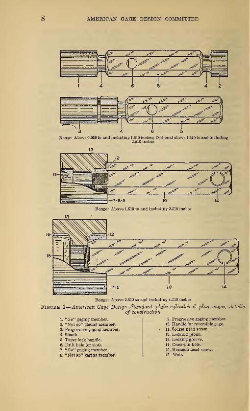
8 AMERICAN GAGE DESIGN COMMITTEE
Range: Above 0.059 to and including 1.510 inches; Optional above 1.510 to and including2.510 inches
Range: Above 2.510 to and including 4.510 inches
Figure 1
—
American Gage Design Standard plain cylindrical plug gages, details
of construction
9. Progressive gaging member.
10. Handle for reversible gage.
• 11. Socket head screw.
12. Locking prong.
13. Locking groove.
1. "Go" gaging member.2. "Not go" gaging member.
3. Progressive gaging member.
4. Shank.
5. Taper lock handle.
6. Drift hole (or slot).
7. "Go" gaging member.8. "Not go" gaging member.
14. Cross-pin hole.
15. Hexagon head screw.
16. Web.
PLUG AND RING GAGE BLANKS 9
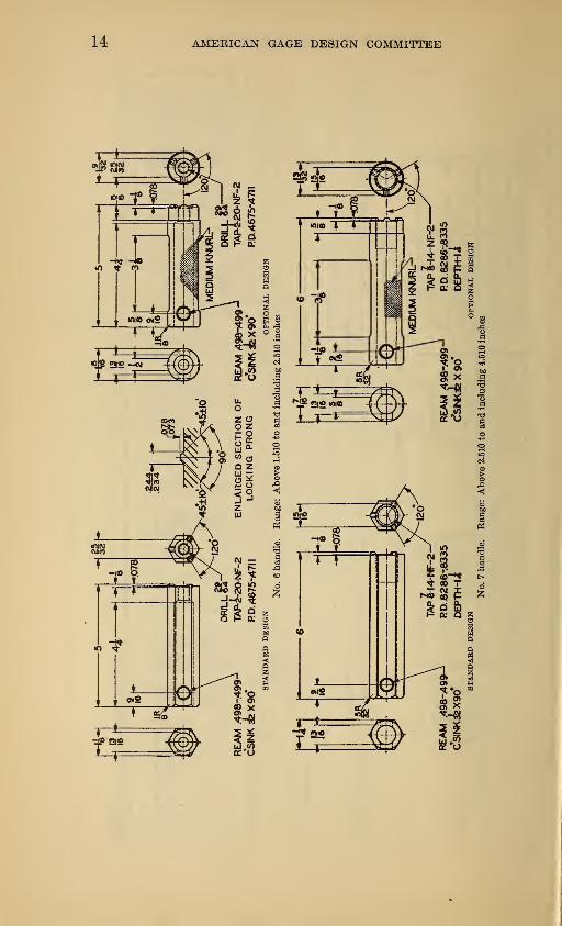
(c) HANDLES
Handles for both taper lock and reversible gages are of the hexag-
onal type. However, the use of round medium-knurled handles,
while not recommended, is made optional in all sizes.
Handles as designed for taper lock and reversible gages offer a
feature of economy in that they may be disassembled from gaging
members when the latter are worn out or discarded for any other
reason, and may then be reassembled with new gaging members, thus
giving them, with reasonable care, practically indefinite life.
PLUG AND RING GAGE BLANKS 11
CO CO iH<N »0 00
I
PLUG AND RING GAGE BLANKS 13
I
9
Z
o o o o o o og <N CO CD CO 00 00
OS C5 GO 00 00 GO GOfMOOOOOOg <M CO -^ CO 00 00 00
ooooooo«TjtHHHrHHHg <N CO "tf CD 00 00 CO
05 O CO 00 00 GO 00gco o o o o o og <M CO CD CO CO 00
!hhhh(N(N(Nooooooo
g <N CO t*< CD 00 00 00
Ci OS GO 00 00 00 GO•gcoooooooe<Mcc*ooooooo
•N^1 x^J* Nr* \rf \oo
>-< OQ <M <M <N CO CO
osiOOiQiOOOOgCO lO 00 rH lO o io£̂O whNM»0>OOiCi»000•§<N CCOOOr-HOO
o o
<v <v
o3 o3
9 co o
ft ao o
bo
#.3
53
IS
1
1
5? a
rH <N CO -tf "5 »C lO
PLUG AND RING GAGE BLANKS
PLUG AND RING GAGE BLANKS

18 AMERICAN GAGE DESIGN COMMITTEE
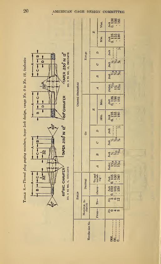
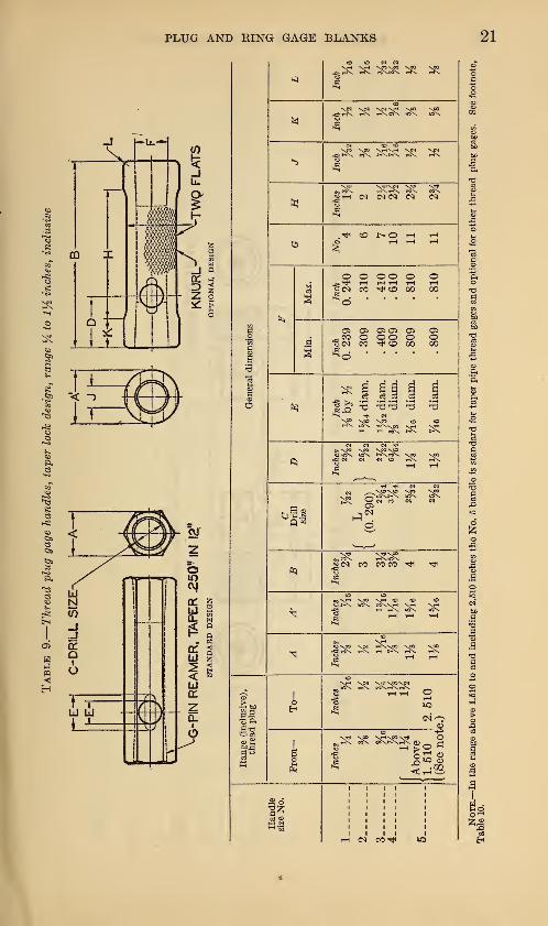
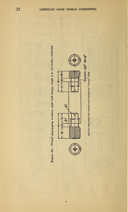
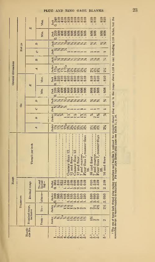
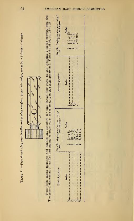
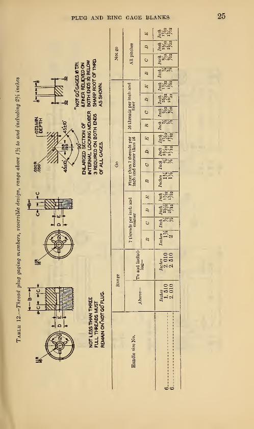
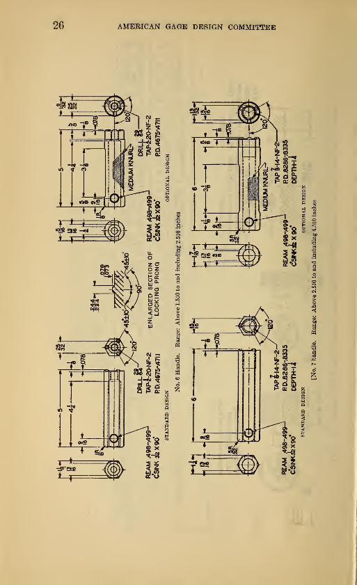
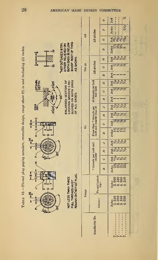
2. THREAD PLUG GAGE BLANKS AND HANDLES
The taper lock and reversible designs have been adopted for
thread plug gage blanks and handles and follow the plain cylindrical
plug gage designs described on pages 6 and 7, with the exception that
the length of thread-gaging members is slightly different in some in-
stances and the use of taper lock blanks and handles for pipe-thread
plug gages is standard to and including 2 inches nominal pipe size.
General details of construction will be apparent from Figure 3.
Data sheets for thread plug gages are set forth on pages 19 to 28,
and a separate table specifying the taper lock handles and gaging
members for pipe-thread plug gages is set forth on page 24.
4 6 5
Range: No. to and including 1.510 inches
7-8 10
Range: Above 1.510 to and including 2.510 inches
Range: Above 2.510 to and including 4.510 inches
Figure 3.
—
American Gage Design Standard thread plug gages, details of con-
struction
1. "Go" gaging member.2. "Not go" gaging member.4. Shank.
5. Taper lock handle.
6. Drift hole (or slot)
.
7. "Go" gaging member.
8. "Not go" gaging member.
10. Handle for reversiblei
11. Socket head screw.
12. Locking prong.
13. Locking groove.
14. Cross-pin hole.
15. Hexagon head screw.
16. Web.
20 AMERICAN GAGE DESIGN COMMITTEE
PLUG AND KING GAGE BLANKS 21
og
2x
-2
v.
to to n e«
X?l \N NT1 X«>' r-fX i-K H\»\ USX
^ C^X ^ ^
o
^ oHZ
o o o ©~» T—I HH«<N CO rJH CD
Sd • ••
© 0> 0505_co o oo"ScN CO Tt< CO
lOX t—\^Q01H IH «X
IN IN <N •«»
eoXt° \n \m v«c<u uix usx t-\wx<M <N H tO
3<N CO COCO
x*COX
tP (O NO h t—
i
^ ^x
aoXT1 X0O X-1 0(0 to
^ 1--X USX MXXjH XrH X^
;^ ^^ 2x ^
^ 2x ^2x^ _2 HH O
(NOCD
3x ^
AMERICAN GAGE DESIGN COMMITTEE
PLUG AND RING GAGE BLANKS 23
oooooooooo,,H rH H i-l H rH H tH rH tH i-H
; <N CO tJ< CO 00 00 00 00 00 00 00 00
o o o o00 00
- 05 OS 00 00 00 00 00 00 00 00 0000 0000•Scoooooooooo oo oo.£ <N CO tH CO 00 00 00 00 00 00 0000 0000
^^ >—ii—i CN C^C<J <N <N <N <N <N <N
^oooooooooo ooo oj; (M CO CO 00 00 00 00 00 00 000000 00
© O 00 00 00 00 00 00 00 OO OO OO OO 00"Sco o o o o o o o o o ooo o^ <M CO CO 00 00 00 00 00 00 000000 00
d '
":'
I \00 \00 \00 \00 VpO -xp0\Q0\Q0 V°0,n\ «\co\oSNco\co\oS\ co\m\c5x co\
"N't vac
IrHrHrHrHrHrH H
grf^*^ ^ ^ ^ ^ ^.g _H ^ _H _H CM^
grHrHrH<N^^^£icb(N ?5 CO <N &
f-i
i c3
1,0
03
26
2 Stfl o
o3
o
ago73 —
IH
" - o3 (h rH
,«50>0>0000000 ooo oSfflHNWrlHrilHHH HHH rHoC0*000rHi0*OOOOO 0>010 *C
^O ' "hi-hhiniNNIN <N <n" c<j o4
gO AO o io »o to o o o o ooo oC^COHINCOCOHHHH HHH rHg (N CO "5 00 rH rH lO lO »0 UJOO OO* ' ' ' H H rH rH rH rH HM'W (M*CO
•i"9̂ ^ "^h rH^HOQ <M <N <N <N^C^
o
So9 «W-53
rH CO «0 >0 »C *0 «0 IQIQIO
AMERICAN GAGE DESIGN COMMITTEE
©
Gaging
member,
use
'
blank
for
range
s^ . . .
o o o<^
hhhN
Handle
No.
oinal
pipe
size
viiii
lijl;Nob
Milacs !HHH(N
aot
go"
Gaging
member,
use
141
blank
for
range-
o o o
Handle
No.
(M CO CO
ssize
S
-aa *
i i i : i
Non
Vgo nj(i vpo s?q -s^
PLUG AND RING GAGE BLANKS
PLUG AND RING GAGE BLANKS
PLUG AND KING GAGE BLANKS
3. PLAIN RING GAGE BLANKS
The use of the solid ring-gage design for external size control,
being fairly well established, the committee's work on plain ring gages
was concerned chiefly with matters of proportion. In the smaller
sizes of plain ring gages it was felt desirable to employ a hardened
bushing pressed into a soft gage body, in place of the one-piece ring
gage, and this design has been adopted in the range above 0.059 to
and including 0.510 inch. The single piece gage is employed in all
cases above 0.510 inch, but gages in sizes above 1.510 inches are
flanged, in order to eliminate unnecessary weight and facilitate
handling.
No dimensional difference exists between "go" and "not go"blanks of identical size range, but an annular groove is provided in
the periphery of "not go" blanks as a means of identification.
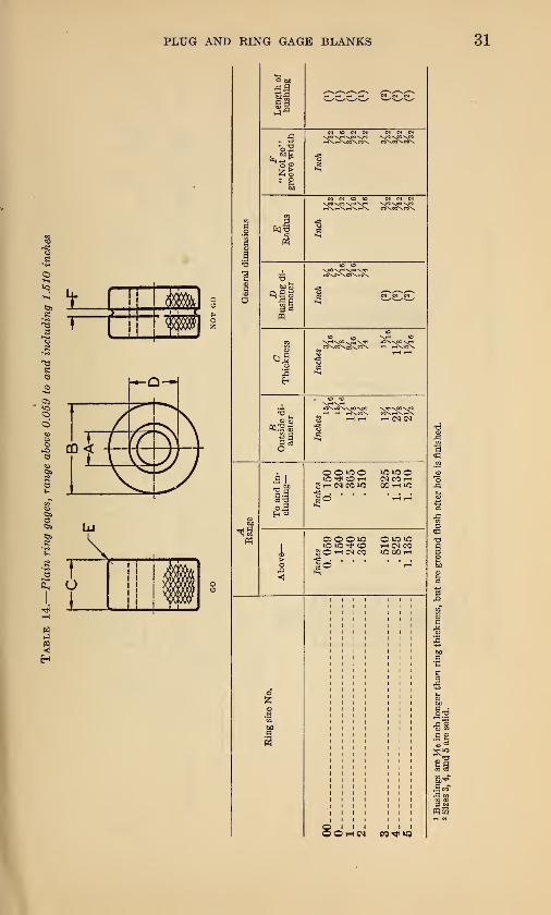
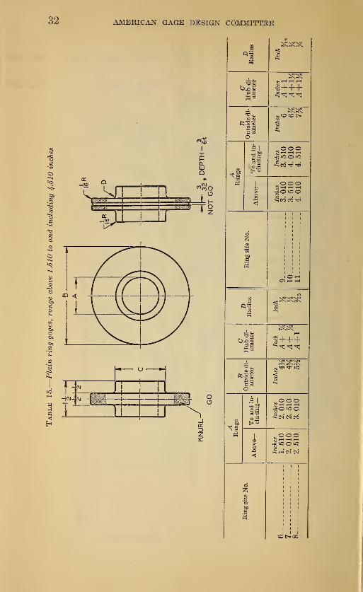
General details of construction are shown in Figure 5, and dimen-
sions are given in Tables 14 and 15.
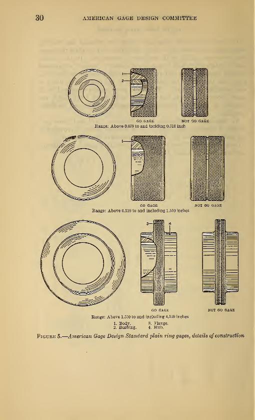
30 AMEKICAN GAGE DESIGN COMMITTEE
GO GAGE NOT GO GAGE
Range: Above 0.510 to and including 1.510 inches
GO GAGE NOT GO GAGE
Range: Above 1.510 to and including 4.510 inches
1. Body. 3. Flange.2. Bushing. 4. Hub.
Figure 5.
—
American Gage Design Standard plain ring gages, details of construction
PLUG AND RING GAGE BLANKS 31
32 AMERICAN GAGE DESIGN COMMITTEE

PLUG AND RING GAGE BLANKS 33
4. THREAD RING GAGE BLANKS
The committee found universal accord as to the superiority of the
adjustable thread ring gage over the solid type, with the result that
all American Gage Design Standard thread ring gage blanks are
equipped with an effective device for adjusting and locking the gage
in the manufacturing or resizing processes. Of the many locking
devices considered the single-unit locking device was finally adopted
as standard, as it permits a minimum diameter of blank for a given
size range, and provides a simple adjustment and positive lock without
introducing any mechanical stresses into the gage body which might
tend to create distortion after setting. Referring to Figure 6, the
construction and operation of this device is as follows
:
The adjusting screw, 8, is threaded externally and internally and
split longitudinally. Turning this screw to the right exerts pressure
on the sleeve, 2, against the shoulder in the left-hand side of the gage
here shown, thus spreading the ring. Once the ring has been properly
adjusted by means of adjusting screw, 8, the adjustment is locked bytightening locking screw, 1. The tightening of locking screw, 1,
exerts a pull between the shoulder immediately under its head andthe internal threads of the adjusting screw, 8, which causes the
adjusting screw to expand into the threads in the wall of the gage, the
thrust of this action being taken up longitudinally by the sleeve, 2,
Therefore, the clamping is accomplished by expansion of the adjusting
screw equally in all directions and not by the application of anyeccentric forces that tend to distort the gage or upset the adjustment.
The locking pressure, it is seen, is taken up centrally in the locking
screw itself as the reacting support is directly under the head of the
locking screw in the form of a shoulder in the gage. The sleeve, 2,
being accurately fitted, serves as a large dowel to maintain the
alignment of the gage.
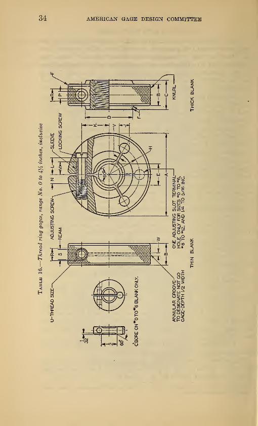
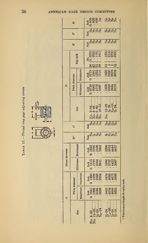
Three types of thread ring gage blanks have been provided as
illustrated in Figure 7, namely:
1. A thin flat disk type with one adjusting slot for all sizes andpitches, both "go" and "not go," No. to % 6 inch, inclusive.
2. A thin flat disk type with two adjusting slots for the following:
(a) All sizes and pitches, "go" and "not go," above % G to and in-
cluding % inch; (b) fine pitches, 1 "go" and "not go," above % to andincluding 4}£ inches; (c) coarse pitches, "not go" only, above % to
and including 4% inches.
3. A thick flanged type with two adjusting slots for all "go" coarse
pitch gages, above % to and including 4% inches.
Dimensions for thread ring gage blanks in the range from No. to
4% unches, inclusive, and of parts for the thread ring gage locking
device, are given in Tables 16, 17, 18, and 19.
1 Specific information as to the meaning of the terms "fine pitches" and "coarse pitches," as used above,
is given in the footnote to Table 16, p, 35.
34 AMEBICAN GAGE DESIGN COMMITTEE
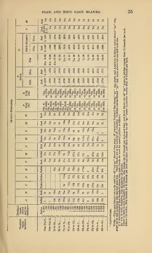
PLUG AND EING GAGE BLANKS 35
|i li'i.l II x s ? s s s
1
i
i lis 1 111 III till
i|l I 1 1 1 § § 1 § | | | |
i?????????????Ill
"
1i
|l 1 1 1 ill 1 11 11 1
i•s S, S .1 § 1 i i 1 1 I 1 g g
41
41 gslslsgglsgsT sf s" $? sf s sf s
*
1 ^^
'
* • « I i * « # * # ^
^
|i x 1 s J 5 f a | |N « <D *> > O (O <0
tqI:
: s ST £ ^ * 2^' X !§ » - w III
; i|
* * * ? 1 1 c # i.x
—K-f ! ! I
* 1. I 1
'|x X ? S « ? X ? & JR ? ? h
jissasiBiSflsssisiniiissiia
H °%ls s s asSBSaa
AMERICAN GAGE DESIGN COMMITTEE
ooo 23§§§*
N MSJO S<0 VJO vJO
^8 r-rxT-rxi-N.i-)\
N <N «* IT
© CO CO i—
I
t> OS i-i COOOHHCM CO CM CM00 i-H t» COrHCMCMCO
S CM CM OtJ< CO CM
CO(—lQ»
..t^OCOrH
£0 T-H rH rH
O O 00 COAO OSt-OOS CM 00*O
OSiO001>^iO 00HO5uNOJ CM CO^OOHH
OO 00 -tf OScm co *or^OS CM 00H (M (M CO
CMt^OOOCOCO"*-* I
' ©
o o o o££££
CM "4h CO rH 2 ^Xu^-eJ?.
6
co co co iaco coo co
«C01>rHCO|hh cm <m
o cooob-OS CM COCM 00 «tf COCO CO ^ lO
^coi>ocorH CM CM
CO 1><N r^-COCS CM ©CMt^^COCO CO lO
O 00 00CO CM CO "3
os cm ooJii-H rH CM CM
OS O »C OS1>ICI>00xsJH O CO 00COtH^io
CM CD CO ©O rjH CO"StH OS CM 00^ i—i t—i CM CM
O''
1*5 TjH OS OSiO <N rfi "O"Ji O CO 00CO ^t"tf lO
.JSK oo cq cm o oo52 ^ CM | CM
ICM rH
00 rH r-K»tf\ c^n^x^xiox
6 6
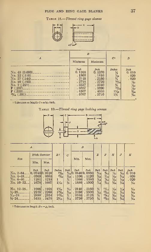
PLUG AND RING GAGE BLANKS 37
Table 18.
—
Thread ring gage sleeves
r
Minimum Maximum
No. 43 (0.089)No. 32 (.116) _
No. 27 (.144) _
No. 10 (.193).No. 2 (.221) __
F (.257)
P (.323)2%4 (.391)___.
Inch
0. 1368. 1808. 2148. 2718. 3337. 3887. 4507. 5707
Inch
0. 1370. 1810. 2150. 2720. 3340. 3890. 4510. 5710
Inches
%Me%
74
IKe1/2
Inch
0. 010. 020.020
Vz2
VZ2
YZ2
%*
i Tolerance on length C=± XM inch.
Table 19.
—
Thread ring gage locking screws
Tl5+7
3*
A D
Pitch diameter c E F H J KSize Min. Max.
Min. Max.
Inch Inch Inches Inch Inch Inch Inch Inch Inch Inch Inch
No. 2-64___ 0. 0745 0. 0759 29/6 4 %4 0. 0840 0. 0860 Vie %2 YZ2 %4 0. 010No. 4-48___ . 0969 . 0985 % %2 . 1100 . 1120 He 3
/l6 YZ23/64 . 020
No. 6-40___ . 1201 . 1218 1 % . 1360 . 1380 Ke 7A2 3/64 Me . 020
No. 10-32 __ . 1678 . 1697 IKe % . 1880 . 1900 Ke %2 ft Me M 2
No. 12-28__ . 1906 . 1928 P/l6 %2 . 2140 . 2160 % U/Z2 Me Me M32
K-28 . 2246 . 2268 l 23/643/l6 . 2480 . 2500 9
/l613/32 Me %4 M32
5/i6-24 . 2830 . 2854 l 23/32 % . 3105 . 3125 % 15/32
5/64
3/32 %4,3/8-24 . 3455 . 3479 2 3A He .3730 . 3750 % 19
/Z25/64 VZ2 %4
1 Tolerance on length B= inch.
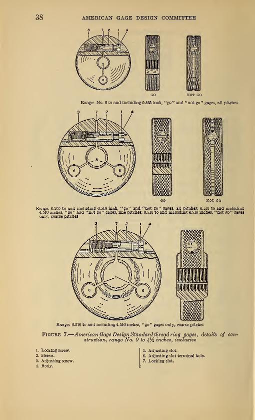
38 AMERICAN GAGE DESIGN COMMITTEE
3 7 2 14
GO NOT GO
Bange: No. to and including 0.365 inch, "go" and "not go" gages, all pitches
3 7 2 14
GO NOT GO
Range: 0.365 to and including 0.510 inch, "go" and "not go" gages, all pitches; 0.510 to and including4.510 inches, "go" and "not go" gages, fine pitches; 0.510 to and including 4.510 inches, "not go" gagesonly, coarse pitches
Range: 0.510 to and including 4.510 inches, "go" gages only, coarse pitches
Figure 7.
—
American Gage Design Standard thread ring gages, details of con-
struction, range No. to 4}i inches, inclusive
1. Locking screw.
2. Sleeve.
3. Adjusting screw.
4. Body.
5. Adjusting slot.
6. Adjusting slot terminal hole.
7. Locking slot.
PLUG AND RING GAGE BLANKS 39
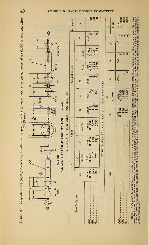
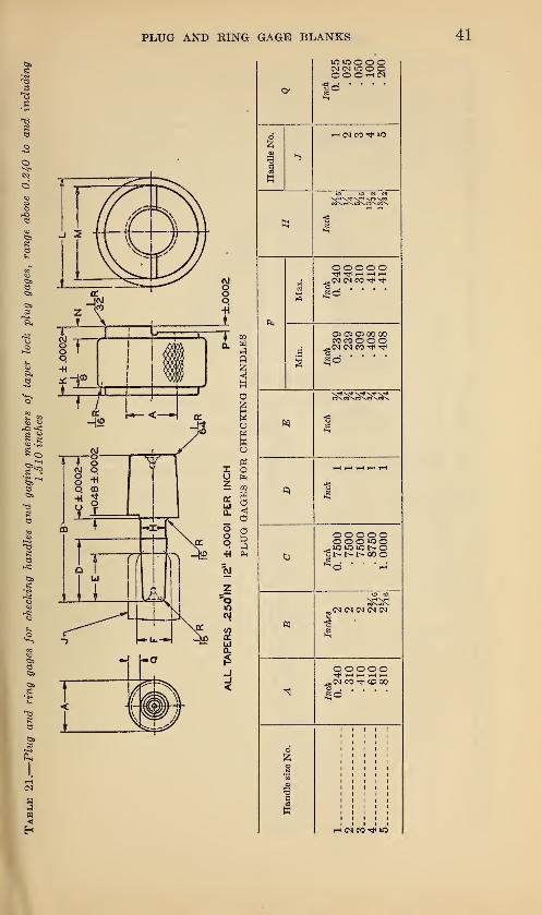
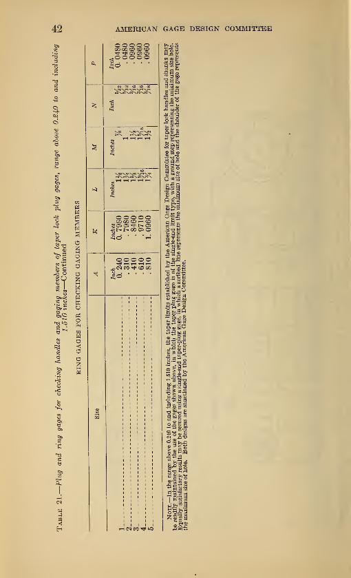
VII. APPENDIX
1. TAPER PLUG AND RING GAGES FOR CHECKING TAPER LOCKHANDLES AND GAGING MEMBERS
It has been deemed advisable to formulate specifications for a
complete set of finished gages for inspecting the taper shanks and
handles of gages of taper lock design.
A complete set consists of a taper plug and a taper ring for each
size range. General details of construction will be apparent fromdrawings, and Tables 20 and 21, on the following pages,
AMERICAN GAGE DESIGN COMMITTEE
It-2
Ii
—
4 .-
-is
_i
—
i
88°O
IQIOO,<N O GO
OiOOO (N iO<C SO <MCO
OCOH<N *C 00
o»oo
iO o
§oooo
o o o00 00 00
<o o ou£d •
o»ooCO O CO
"iO CO CO
d *'
CO CO i—i
<N *C GO
o88.
PLUG AND KING GAGE BLANKS
i
9
WiOOOOO O O (N
Handle
No.
i—I C5J CO Tt< »o
to (0 M W
<;t->
Max.
o o o o oTfrl ^ h rH tH
^(M <M CO tJH
Min.
O 05 C5 00 00co co
^(NlNCO^r^
Kl6
Inch
o
OOOOOOOOiOO_,*o *o »ouNNNGOO*.d " * -
to to
OOOOO^ rt rH(NCOThOOO
Handle
size
No.
th csi co »d
AMERICAN GAGE DESIGN COMMITTEE
o o o o o00 00 CD CO COtJH OS OS OS.OOOOO
£0
CN CN CO CD)\HV-
OOOOOCO 00 CO i-t CO
2 OS OS !>• Os•£l>l>00OsO
OOOOOTjiHHiHH<N CO CO 00
£0
allw cd £
ft
03 d ©wd,d® 0*"
sag
glS>-< d§ S CD
Ji-2 ft<1 bigCD
>>J3 CD
CD K 3,d 52 h h00 ds © M 9
£3 ft p ©
ftcD^O
5-oft-nd £ ®
8 £ ft 5•a2.S <Dpi
"JT a> 9
•31*5-3 ^210 B fl
9 wg>
S?3 So
I 13
1 ail
PLUG AND RING GAGE BLANKS 43
2. OFFICIAL MONOGRAM FOR DESIGNATING PRODUCTS MADE TOAMERICAN GAGE DESIGN STANDARDS
The optional use of the monogram shown in Figure 8, to identify
gages made to American Gage Design Standards, is sanctioned by
the committee. The monogram, it will be noted, consists of the initials
"AD," the right hand side of the "A" and the straight side of the
"D" being common. The monogram, if used, should be placed
adjacent to the maker's trade-mark.
Figure 8.
—
Official monogram for des-
ignating products made to AmericanGage Design Standards
3. APPLICATION OF AMERICAN GAGE DESIGN STANDARDS TOSPECIAL TYPES OF GAGES, RECOMMENDED PRACTICE
While the American Gage Design Standards have been adopted
with specific types and sizes of gages in mind, it is recommendedthat standard blanks and handles be used wherever practicable in
the design and manufacture of special gages, the design of which did
not come within the scope of the committee's work.
Where lengths and diameters are entirely special and blanks of
standard dimensions can not be utilized, it is further recommendedthat standard handles and fittings be used.
Observance of this practice will tend to reduce costs and facilitate
procurement.
VIII. INDEXPage
Adjusting slots (definition) 6
American Gage Design Committee 1
members 3
purpose 1
organization 1,3
American Gage Design Standards 1
advantages 2
availability 1
applications to special-type gages 43
(definition) 5
details of construction 6
development of 1
effective date. 2
official monogram _ . . . . 43
Conference, general 2
Cross pin 15,27
hole 8,18
Definitions 5
Development of standards 1
Drift hole (or slot) 7
(definition) 6
(illustration) 8,18
Flange, ring gage 29
(definition) 6
(illustration) __ 30
Gages for taper lock gages 39
Gaging member (definition) 5
section (definition) 5
"Go" and "not go" gages 7,29,33
Groove for "not go" gages 7,29
locking 5
Handle, gage 9
(definition) 6
(description) 9
hexagon _ 9
(illustration) 8,18
knurled 9
Hole, cross-pin 8, 18
drift (definition) 6
Holes, lightening (definition) 6
Hub (definition) 6
Lightening holes (definition).. 6
Locking device, thread ring gages (defini-
tion) 6
(illustration) 33,38
groove 5
prong.. 5
slot (definition).. 6
Member, gaging 5
Monogram, official 43
Not go gages, groove to distinguish 7,29
Official monogram 43
Optional use of taper lock gages 7
Pin, cross 17,27
Pipe thread plug gages 18, 24
Pitches, coarse and fine.,.. „„„,,„„„* 33,35
PagePlain cylindrical plug gages 6
(definition)... 5
(description) 6
(illustration) 8
ring gages. 29
bushing in 29
(definition) 6
(description) 29
flanged .». 29
(illustrations) 30
solid design 29
Plug gage, plain cylindrical 6
(definition) 5
(description) 6
progressive 5
pipe thread... 18,24
progressive 5
reversible 5,
7
taper lock 5,7
thread . 5,18
(definition) 5
(description) __ 18
pipe 18,24
Progressive cylindrical plug gage (definition).. 5
gaging member 8
Prong, locking 5
Reversible plug gage (definition) 5
Ring gage, plain (definition) 6
thread (definition) 6
Section, gaging 5
Shank (definition) 5
Slot, drift (definition) 6
locking (definition) 6
Slots, adjusting (definition). 6
Special types of gages 43
Standards. (See American Gage Design.)
Taper lock (definition) 5
design (description) 7
optional range 7
standard range 7,18
Terminology 5
Thread plug gage. 18
(definition) 5
(description) 18
(illustration) 18
ring gage 33
adjustable design 33
adjusting screws 33, 36
(definition) 6
(description) 33
(illustration). 33,38
locking device 33,38
locking screws 33,37
types of, three. 33
Web — 8,18
Wink 7
45
o


i